WO2016111183A1 - アンテナ装置 - Google Patents
アンテナ装置 Download PDFInfo
- Publication number
- WO2016111183A1 WO2016111183A1 PCT/JP2015/086046 JP2015086046W WO2016111183A1 WO 2016111183 A1 WO2016111183 A1 WO 2016111183A1 JP 2015086046 W JP2015086046 W JP 2015086046W WO 2016111183 A1 WO2016111183 A1 WO 2016111183A1
- Authority
- WO
- WIPO (PCT)
- Prior art keywords
- phase
- antenna element
- antenna
- feeding
- polarization
- Prior art date
- Legal status (The legal status is an assumption and is not a legal conclusion. Google has not performed a legal analysis and makes no representation as to the accuracy of the status listed.)
- Ceased
Links
Images







Classifications
-
- H—ELECTRICITY
- H01—ELECTRIC ELEMENTS
- H01Q—ANTENNAS, i.e. RADIO AERIALS
- H01Q1/00—Details of, or arrangements associated with, antennas
- H01Q1/27—Adaptation for use in or on movable bodies
- H01Q1/28—Adaptation for use in or on aircraft, missiles, satellites, or balloons
-
- H—ELECTRICITY
- H01—ELECTRIC ELEMENTS
- H01Q—ANTENNAS, i.e. RADIO AERIALS
- H01Q13/00—Waveguide horns or mouths; Slot antennas; Leaky-waveguide antennas; Equivalent structures causing radiation along the transmission path of a guided wave
- H01Q13/08—Radiating ends of two-conductor microwave transmission lines, e.g. of coaxial lines, of microstrip lines
-
- H—ELECTRICITY
- H01—ELECTRIC ELEMENTS
- H01Q—ANTENNAS, i.e. RADIO AERIALS
- H01Q21/00—Antenna arrays or systems
- H01Q21/06—Arrays of individually energised antenna units similarly polarised and spaced apart
-
- H—ELECTRICITY
- H01—ELECTRIC ELEMENTS
- H01Q—ANTENNAS, i.e. RADIO AERIALS
- H01Q3/00—Arrangements for changing or varying the orientation or the shape of the directional pattern of the waves radiated from an antenna or antenna system
- H01Q3/26—Arrangements for changing or varying the orientation or the shape of the directional pattern of the waves radiated from an antenna or antenna system varying the relative phase or relative amplitude of energisation between two or more active radiating elements; varying the distribution of energy across a radiating aperture
- H01Q3/30—Arrangements for changing or varying the orientation or the shape of the directional pattern of the waves radiated from an antenna or antenna system varying the relative phase or relative amplitude of energisation between two or more active radiating elements; varying the distribution of energy across a radiating aperture varying the relative phase between the radiating elements of an array
Definitions
- the present disclosure relates to an antenna device.
- This application is based on Japanese Patent Application No. 2015-000250 filed on January 5, 2015, and claims the benefit of priority thereto, the entire contents of which are referred to Is incorporated herein by reference.
- Patent Document 1 includes a phased array antenna having a plurality of antenna elements, and controls the phase shifter (phase shifter) of each antenna element according to a directivity direction error.
- the satellite to be controlled is described.
- the antenna element Since the wavelength of radio waves in the VHF band is several meters and is relatively large, the antenna element also increases in accordance with the wavelength. For this reason, when using the phased array antenna of patent document 1 for transmission / reception of the radio wave of a VHF band, since the phased array antenna is provided with the several antenna element, each antenna element becomes large. As a result, the installation space for the antenna device is significantly increased, and the weight of the antenna device is also increased. Therefore, it may become an obstacle to the application to a flying object such as a satellite which is strongly demanded to be smaller and lighter.
- This disclosure describes an antenna device that can be reduced in size and weight without reducing communication efficiency.
- the antenna device is an antenna device that is mounted on a flying object and transmits / receives radio waves in the VHF band.
- the antenna device includes a first antenna element including an element having a shape in which a portion from a feeding point to a tip has a length component in a first direction and a length component in a second direction orthogonal to the first direction.
- a second antenna element including an element having a shape in which a portion from the feeding point to the tip has a length component in the first direction and a length component in the second direction, and a first of the first antenna element
- the direction of polarization of the antenna device is controlled by adjusting the feed phase and the second feed phase of the second antenna element, or the first composite phase of the first antenna element and the second composite phase of the second antenna element.
- a phase shifter The first antenna element and the second antenna element are biased in the first direction when the first feeding phase and the second feeding phase are in phase with each other, or when the first synthesis phase and the second synthesis phase are in phase with each other.
- the wave components are arranged so as to strengthen each other and the polarization components weaken each other in the second direction.
- the antenna device can be reduced in size and weight without reducing the communication efficiency.
- FIG. 1 It is a schematic block diagram of the satellite carrying the antenna device which concerns on 1st Embodiment. It is a schematic block diagram of the antenna device mounted in the satellite of FIG. It is a figure which shows the example of arrangement
- (A) is a figure for demonstrating an example of the polarization component of each antenna element of FIG. 6, (b) is the directivity pattern of the antenna apparatus of FIG. 6 when the direction of the main polarization is directed in the Y-axis direction. It is a figure which shows an example.
- (A) is a figure for demonstrating another example of the polarization component of each antenna element of FIG. 6, (b) is the directivity of the antenna apparatus of FIG. 6 when the main polarization direction is directed in the X-axis direction. It is a figure which shows an example of a sex pattern.
- (A) is a figure which shows an example of the directivity pattern of the antenna apparatus of FIG.
- FIG. 6 shows an example of a directivity pattern of the antenna apparatus of FIG. 6 at the time of directing the direction of main polarization to directions other than an X-axis direction and a Y-axis direction
- FIG. 6A is a diagram illustrating an example of a directivity pattern of the antenna device of FIG. 6 when the directivity is tilted in the ⁇ Y direction
- FIG. 6B is a diagram of the antenna device of FIG. 6 when the directivity is tilted in the + Y direction.
- FIG. 6 shows an example of the directivity pattern of the antenna apparatus of FIG. 6 when the directivity is tilted in the + X direction.
- An antenna device is an antenna device that is mounted on a flying object and transmits / receives radio waves in the VHF band.
- the antenna device includes a first antenna element including an element having a shape in which a portion from a feeding point to a tip has a length component in a first direction and a length component in a second direction orthogonal to the first direction.
- a second antenna element including an element having a shape in which a portion from the feeding point to the tip has a length component in the first direction and a length component in the second direction, and a first of the first antenna element
- the direction of polarization of the antenna device is controlled by adjusting the feed phase and the second feed phase of the second antenna element, or the first composite phase of the first antenna element and the second composite phase of the second antenna element.
- a phase shifter The first antenna element and the second antenna element are biased in the first direction when the first feeding phase and the second feeding phase are in phase with each other, or when the first synthesis phase and the second synthesis phase are in phase with each other.
- the wave components are arranged so as to strengthen each other and the polarization components weaken each other in the second direction.
- the first antenna element when the first feeding phase and the second feeding phase are in phase with each other, or when the first synthesis phase and the second synthesis phase are in phase with each other, the first antenna element first The polarization component in the direction and the polarization component in the first direction of the second antenna element strengthen each other, and the polarization component in the second direction of the first antenna element and the polarization component in the second direction of the second antenna element Since the antenna devices weaken each other, the main polarization direction of the antenna device is the first direction.
- the polarization component in the first direction of the first antenna element and the second antenna weakens each other, and the polarization component in the second direction of the first antenna element and the polarization component in the second direction of the second antenna element strengthen each other.
- the main polarization direction is the second direction.
- the communicable area can be controlled in an intended direction, and congestion of signals received by the satellite can be prevented.
- congestion area is unevenly distributed on the earth, an antenna pattern having an intention of avoiding a signal in the congestion area can be obtained.
- the antenna device since the antenna device only needs to include the first antenna element and the second antenna element, the number of antenna elements can be reduced as compared with the phased array antenna. As a result, it is possible to reduce the size and weight without reducing the communication efficiency.
- the phase shifter adjusts the first feeding phase and the second feeding phase so as to be in phase with each other, or adjusts the first synthesis phase and the second synthesis phase so as to be in phase with each other. May be.
- the main polarization direction of the antenna device can be set to the first direction.
- the main polarization direction of the antenna device can be set to the second direction. In this way, the main polarization direction of the antenna device can be switched to either the first direction or the second direction orthogonal to each other.
- the first antenna element and the second antenna element may be inverted F antennas.
- the size per element of the inverted F-type antenna is, for example, about 0.25 wavelength ⁇ 0.05 wavelength ⁇ 0.01 wavelength. For this reason, the first antenna element and the second antenna element can be reduced in size and weight, and the antenna device can be further reduced in size and weight.
- An antenna device includes a third antenna including an element in which a portion from a feeding point to a tip has a shape having a length component in a first direction and a length component in a second direction.
- the element and the portion from the feed point to the tip may further include a fourth antenna element including an element that has a shape having a length component in the first direction and a length component in the second direction.
- the phase shifter further adjusts the third feed phase of the third antenna element and the fourth feed phase of the fourth antenna element, or the third composite phase of the third antenna element and the fourth composite phase of the fourth antenna element.
- the direction of polarization may be controlled.
- the third antenna element and the fourth antenna element are biased in the first direction when the third feeding phase and the fourth feeding phase are in phase with each other, or when the third synthesis phase and the fourth synthesis phase are in phase with each other.
- the wave components may be arranged to strengthen each other, and the polarization components may weaken each other in the second direction.
- the first antenna element and the third antenna element have a first direction when the first feeding phase and the third feeding phase are opposite to each other, or when the first and third synthesis phases are opposite to each other. May be arranged such that the polarization components strengthen each other and the polarization components weaken each other in the second direction.
- the second antenna element and the fourth antenna element have the first direction when the second feeding phase and the fourth feeding phase are opposite to each other, or when the second and fourth synthesis phases are opposite to each other. May be arranged such that the polarization components strengthen each other and the polarization components weaken each other in the second direction.
- 4 combined phases the first feed phase (first composite phase) and the third feed phase (third composite phase), and the second feed phase (second composite phase) and the fourth feed phase (first feed phase).
- the main polarization direction of the antenna device can be set to the first direction.
- the (fourth combined phase) is opposite to each other, the first feeding phase (first combined phase) and the third feeding phase (third combined phase), the second feeding phase (second combined phase), and the fourth feeding phase.
- the main polarization direction of the antenna device can be set to the second direction.
- the ratio between the magnitude of the polarization component in the first direction and the magnitude of the polarization component in the second direction changes according to the phase difference.
- the angle formed between the main polarization direction of the antenna device and the first direction can be adjusted, and the polarization direction of the antenna device can be controlled to a desired direction.
- the communicable area can be controlled in an intended direction, and congestion of signals received by the satellite can be prevented.
- the antenna device since the antenna device only needs to include the first antenna element, the second antenna element, the third antenna element, and the fourth antenna element, the number of antenna elements can be reduced as compared with the phased array antenna. As a result, it is possible to reduce the size and weight without reducing the communication efficiency.
- the phase shifter adjusts the first feeding phase and the fourth feeding phase to be opposite to each other, and adjusts the second feeding phase and the third feeding phase to be opposite to each other, or
- the first synthesized phase and the fourth synthesized phase may be adjusted to be opposite to each other, and the second synthesized phase and the third synthesized phase may be adjusted to be opposite to each other.
- the phase difference of the first feed phase (first composite phase) with respect to the third feed phase (third composite phase) is the fourth feed phase (fourth composite phase) with respect to the second feed phase (second composite phase). Is equal to the phase difference.
- the ratio between the magnitude of the polarization component in the first direction and the magnitude of the polarization component in the second direction changes according to this phase difference.
- the main polarization direction of the antenna device can be set to a desired direction on a plane defined by the first direction and the second direction.
- the phase shifter adjusts the first feeding phase and the second feeding phase to be opposite to each other, and adjusts the third feeding phase and the fourth feeding phase to be opposite to each other, or
- the first synthesized phase and the second synthesized phase may be adjusted to be opposite to each other, and the third synthesized phase and the fourth synthesized phase may be adjusted to be opposite to each other.
- the phase difference of the third feed phase (first composite phase) with respect to the first feed phase (first composite phase) is the fourth feed phase (fourth composite phase) with respect to the second feed phase (second composite phase). Is equal to the phase difference.
- the directivity of the antenna device tilts in a direction that cancels out the phase difference. Since the phase difference occurs in the first direction, the directivity of the antenna device can be tilted (shifted) in the first direction by this phase difference.
- the phase shifter adjusts the first feeding phase and the third feeding phase to be in phase with each other, and adjusts the second feeding phase and the fourth feeding phase to be in phase with each other, or the first synthesis
- the phase and the third synthesized phase may be adjusted to be in phase with each other, and the second synthesized phase and the fourth synthesized phase may be adjusted to be in phase with each other.
- the first power supply phase (first composite phase) and the third power supply phase (third composite phase) are in phase with each other
- the polarization component is strengthened in the second direction. For this reason, the directivity of the antenna device is in the second direction.
- the phase difference of the second feed phase (second composite phase) with respect to the reverse phase of the first feed phase (first composite phase) is the fourth feed phase (with respect to the reverse phase of the third feed phase (third composite phase)). It is equal to the phase difference of (fourth synthesized phase).
- the directivity of the antenna device tilts in a direction that cancels out the phase difference. Since the phase difference occurs in the second direction, the directivity of the antenna device can be tilted in the second direction by this phase difference.
- the third antenna element and the fourth antenna element may be inverted F type antennas.
- the size per element of the inverted F-type antenna is, for example, about 0.25 wavelength ⁇ 0.05 wavelength ⁇ 0.01 wavelength. For this reason, the third antenna element and the fourth antenna element can be reduced in size and weight, and the antenna device can be further reduced in size and weight.
- VHF radio waves may include AIS signals.
- the phase shifter may control the direction of polarization so that the sensitivity of the ship dense area decreases.
- a route for a plurality of ships is set, which may be a dense area where ships are concentrated.
- the AIS signal is congested because the AIS signal is transmitted from a plurality of ships in such a sea area.
- the signal reception rate may decrease. For this reason, the number of AIS signals arriving at the antenna device can be reduced by controlling the direction of polarization of the antenna device so that the sensitivity of the ship dense area is lowered, and the reception rate of the AIS signal is improved. Is possible.
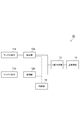
- FIG. 1 is a schematic configuration diagram of a satellite equipped with an antenna device according to the first embodiment.
- the satellite 1 is, for example, a small satellite having a weight of 200 kg or less and a side size of, for example, two wavelengths or less, and orbits a low orbit with an altitude of about 500 to 700 km.
- the satellite 1 is equipped with, for example, an automatic identification system (AIS).
- AIS automatic identification system
- the satellite 1 includes a main body 2 in which various devices for the satellite 1 are accommodated, a panel 3 for photovoltaic power generation, and an antenna device 10 for transmitting and receiving signals to and from a ground station (see FIG. 2). And comprising.
- the width direction of the panel 3 is the X axis
- the length direction of the panel 3 of the satellite 1 is the Y axis
- the height direction of the main body 2 is the Z axis
- the intersection of the X axis, the Y axis, and the Z axis Assume that satellite 1 is located and the earth is in the + Z direction.
- AIS is a device that is required to be installed on large ships of 300 tons or more.
- the large ship transmits an AIS signal including information such as the position, course and speed of the ship, and identifies the other ship by receiving the AIS signal from the other ship.
- An AIS signal from a coastal ship is received by a coastal station or the like, and the operation of the ship is managed. Since the receivable area of the coastal station is about 70 km in radius, an AIS signal is received by mounting an AIS on a satellite, an aircraft, or the like in a sea area farther from the coast than the receivable area.
- the AIS signal is transmitted / received using a radio wave having a frequency of about 160 MHz in a VHF (Very High Frequency) band.
- Ground stations (large ships and coastal stations) transmit AIS signals by vertical polarization, for example.
- FIG. 2 is a schematic configuration diagram of the antenna device 10.
- FIG. 3 is a diagram illustrating an arrangement example of each antenna element.
- the antenna device 10 is mounted on the satellite 1 and transmits / receives VHF band radio waves.
- the antenna device 10 can change the direction of polarization of the antenna device 10.
- the antenna device 10 includes an antenna element 11a (first antenna element) and an antenna element 11b (second antenna element), a phase shifter 12a and a phase shifter 12b, and distribution and combination.
- the antenna element 11a and the antenna element 11b are elements for transmitting and receiving VHF band radio waves.
- the antenna element 11a and the antenna element 11b transmit radio waves generated in space during transmission or reception on an XY plane defined by an X-axis direction (second direction) and a Y-axis direction (first direction) orthogonal to each other. It includes an element that can be decomposed into a polarization component in the X-axis direction and a polarization component in the Y-axis direction.
- the antenna element 11a and the antenna element 11b have a shape in which the portion from the feeding point of the element to the tip of the element has a length component in the X-axis direction and a length component in the Y-axis direction. ing.
- the length component in the X-axis direction and the length component in the Y-axis direction are, for example, about 1/100 wavelength to 1 wavelength.
- Examples of such an antenna element include an inverted F-type antenna, an inverted L-type antenna, a microstrip antenna, and a monopole antenna that is inclined with respect to a symmetry line.
- description will be made assuming that the antenna element 11a and the antenna element 11b are inverted-F antennas.
- the antenna element 11 a and the antenna element 11 b include a radiation element 111, a short-circuit element 112, and a power feeding element 113.
- the radiating element 111 extends in the Y-axis direction, and extends substantially parallel to the housing of the satellite 1 (including the main body 2 and the panel 3). One end 111a of the radiating element 111 forms the tip of the element.
- the short-circuit element 112 is an element connected to the ground point of the satellite 1.
- the short-circuit element 112 extends from the other end of the radiation element 111 to the housing of the satellite 1 in the X-axis direction.
- the feeding element 113 is an element fed from the feeding point 114 of the satellite 1.
- the feeding element 113 is disposed substantially parallel to the short-circuit element 112 and extends from the radiating element 111 to the feeding point 114 in the X-axis direction.
- the angle formed between the radiating element 111 and the short-circuit element 112 and the angle formed between the radiating element 111 and the feeding element 113 are substantially perpendicular.
- the length in the X-axis direction of the antenna element 11a and the antenna element 11b thus configured is, for example, about 0.05 wavelength
- the length in the Y-axis direction is, for example, about 0.25 wavelength.
- the length in the Z-axis direction is, for example, about 0.01 wavelength.
- the antenna element 11a When the antenna device 10 functions as a transmitting antenna, the antenna element 11a is fed with the first feeding phase, and the antenna element 11b is fed with the second feeding phase.
- the received signal of the antenna element 11a When the antenna device 10 functions as a receiving antenna, the received signal of the antenna element 11a is combined with the first combined phase, and the received signal of the antenna element 11b is combined with the second combined phase.
- the electric field generated when transmitting and receiving radio waves is polarized in the XY plane as a polarization component A1 that is a polarization component in the Y-axis direction and a polarization component that is a polarization component in the X-axis direction. It can be decomposed into a wave component B1.
- the electric field generated when radio waves are transmitted / received is a polarization component A2 that is a polarization component in the Y-axis direction and a polarization component that is a polarization component in the X-axis direction in the XY plane. It can be decomposed into component B2.
- the polarization component A1 and the polarization component A2 are stronger than each other.
- the polarization component B1 and the polarization component B2 are arranged so as to weaken each other.
- the polarization component A1 and the polarization component A2 are arranged so that the polarization component B1 and the polarization component B2 strengthen each other.
- the polarization component A1 and the polarization component A2 are line symmetric with respect to the center line C1 of the satellite 1 in the X-axis direction
- the antenna element 11a and the antenna element 11b are arranged so that the polarization component B1 and the polarization component B2 are axisymmetric with respect to the center line C1.
- the X-axis length component (feeding element 113) of the element of the antenna element 11a extends with reference to the feeding point 114, and the X-axis length component of the antenna element 11b (feeding element 113). ) are opposite to each other in the direction extending with respect to the feeding point 114. Further, the length component (radiating element 111) in the Y-axis direction of the element of the antenna element 11a extends with reference to the feeding point 114, and the length component (radiating element 111) in the Y-axis direction of the element of the antenna element 11b. The direction extending with reference to the feeding point 114 is the same.
- the antenna element 11a and the antenna element 11b are located in substantially the same plane, and are arranged substantially symmetrically with respect to the center line C1.
- the term “substantially in the same plane” includes the case where the distance is 0.25 wavelength or less from the same plane and the same plane.
- the term “substantially line symmetric” includes complete line symmetry and a case where the position is shifted by 0.25 wavelength or less from the position of complete line symmetry.
- the distance between the antenna element 11a and the antenna element 11b is about one wavelength or less. About one wavelength is, for example, 0.25 wavelength or more and 1.5 wavelengths or less.
- the phase shifter 12a is a circuit that adjusts the first feeding phase and the first combined phase.
- the phase shifter 12a adjusts the first feeding phase.
- the phase shifter 12a adjusts the first combined phase.
- the phase shifter 12b is a circuit that adjusts the second feeding phase and the second combined phase.
- the phase shifter 12b adjusts the second feeding phase when the antenna device 10 functions as a transmission antenna.
- the phase shifter 12b adjusts the second combined phase.
- the distribution synthesizer 13 is a circuit that performs signal distribution and synthesis.
- the distribution synthesizer 13 distributes the signal from the transceiver 14 to the antenna element 11a and the antenna element 11b.
- the distribution synthesizer 13 receives signals received by the antenna elements 11a and 11b and synthesizes these received signals.
- the transceiver 14 is a circuit that generates a signal and processes the received signal.
- the transceiver 14 When the antenna device 10 functions as a transmission antenna, the transceiver 14 outputs a signal subjected to various processes such as modulation to the distribution synthesizer 13.
- the transceiver 14 receives the signal synthesized by the distribution synthesizer 13 and performs various processes such as demodulation.
- the control unit 15 is configured by, for example, a processor.
- the control unit 15 controls the phase shifter 12a to adjust the first feeding phase, and controls the phase shifter 12b to adjust the second feeding phase.
- the direction of polarization of the antenna device 10 is controlled.
- the control unit 15 receives a control command from the ground station, and controls the first feeding phase of the phase shifter 12a and the second feeding phase of the phase shifter 12b in accordance with the received control command.
- the control unit 15 controls the phase shifter 12a to adjust the first synthesized phase, and controls the phase shifter 12b to adjust the second synthesized phase.
- the direction of polarization of the antenna device 10 is controlled.
- the control unit 15 receives a control command from the ground station, and controls the first combined phase of the phase shifter 12a and the second combined phase of the phase shifter 12b in accordance with the received control command.
- FIG. 4A is a diagram for explaining an example of the directivity pattern of the antenna device 10.
- the first power feeding phase and the second power feeding phase are set to the same phase by the phase shifter 12a and the phase shifter 12b.
- the synthesized wave obtained by synthesizing the radio wave radiated from includes a polarization component A. That is, since the polarization component A1 and the polarization component A2 are in phase with each other, the polarization component A in the Y-axis direction of the composite wave is the sum of the polarization component A1 and the polarization component A2 on the plane P.
- the polarization component B1 and the polarization component B2 are opposite in phase, and the distance from the antenna element 11a to the plane P and the distance from the antenna element 11b to the plane P are equal to each other.
- the components B2 cancel each other in the plane P.
- the main polarization direction of the antenna device 10 that is, the main polarization direction of the satellite 1 is the Y-axis direction (+ Y direction).
- the polarization of the ground station is vertical polarization and the earth is in the + Z direction
- the polarization of the satellite 1 and the polarization of the ground station match in the Y-axis direction. For this reason, the radio wave reception sensitivity in the Y-axis direction increases.
- the radio wave reception sensitivity in the X-axis direction is reduced. As a result, the directivity pattern D shown in FIG.
- FIG. 4B is a diagram for explaining another example of the directivity pattern of the antenna device 10.
- the first power feeding phase and the second power feeding phase are set to opposite phases by the phase shifter 12a and the phase shifter 12b.
- the polarization component A1 and the polarization component A2 are opposite in phase, and the distance from the antenna element 11a to the plane P and the distance from the antenna element 11b to the plane P are equal to each other.
- the wave components A2 cancel each other in the plane P.
- the polarization component B in the X-axis direction of the combined wave is the sum of the polarization component B1 and the polarization component B2.
- the main polarization direction of the antenna device 10 that is, the main polarization direction of the satellite 1 is the X-axis direction (+ X direction).
- the polarization of the ground station is vertical polarization and the earth is in the + Z direction
- the polarization of the satellite 1 and the polarization of the ground station match in the X-axis direction. For this reason, the radio wave reception sensitivity in the X-axis direction increases.
- the radio wave reception sensitivity in the Y-axis direction is reduced. As a result, the directivity pattern D shown in FIG. 4B is obtained.
- the antenna device 10 when the first feeding phase (first combined phase) and the second feeding phase (second combined phase) are in phase with each other, the polarization component A1 of the antenna element 11a. And the polarization component A2 of the antenna element 11b strengthen each other, and the polarization component B1 of the antenna element 11a and the polarization component B2 of the antenna element 11b weaken each other. For this reason, the main polarization direction of the antenna device 10 can be set to the Y-axis direction by setting the first feeding phase (first synthesized phase) and the second feeding phase (second synthesized phase) to be in phase with each other. .
- the main polarization direction of the antenna device 10 can be set to the X-axis direction by setting the first feeding phase (first combined phase) and the second feeding phase (second combined phase) to be opposite to each other. it can. In this way, the main polarization direction of the antenna device 10 can be switched between the X-axis direction and the Y-axis direction.
- the communicable area can be controlled in an intended direction, and congestion of signals received by the satellite 1 can be prevented.
- the antenna device 10 since the antenna device 10 only needs to include the antenna elements 11a and 11b as antenna elements, the number of antenna elements can be reduced as compared with the phased array antenna. As a result, the antenna device 10 can be reduced in size and weight without reducing communication efficiency.
- the AIS signal received by the satellite may be congested, and the AIS signal reception rate may be reduced. Further, since the AIS signal from the ship in the dense region of the ship can be received by the coastal station or the like, it is not necessary for the satellite to receive the AIS signal from the ship in the dense region of the ship.
- the direction of the polarization of the satellite 1 is adjusted so that the polarization of the radio wave transmitted from the ship existing in the ship dense area is orthogonal to the polarization of the satellite 1 (antenna device 10).
- the sensitivity of the antenna device 10 can be lowered with respect to the ship dense area, and the number of AIS signals received by the satellite 1 can be reduced.
- the AIS signal reception rate can be improved.
- an inverted F-type antenna can be used as the antenna element 11a and the antenna element 11b.
- a cross dipole antenna can be used as an antenna element that can adjust the direction of polarization by a method different from that of the antenna device 10.
- the size of the cross dipole antenna per element is 0.5 wavelength ⁇ 0.5 wavelength ⁇ 0. .25 wavelengths.
- the size per element of the inverted F-type antenna is about 0.25 wavelength ⁇ 0.05 wavelength ⁇ 0.01 wavelength.
- the weight of the inverted F-type antenna is about one tenth of the weight of the cross dipole antenna. For this reason, the antenna element 11a and the antenna element 11b can be reduced in size and weight, and the antenna device 10 can be further reduced in size and weight. As a result, the mountability of the antenna device 10 on the satellite 1 is improved.
- FIG. 5 is a schematic configuration diagram of a satellite equipped with the antenna device according to the second embodiment. As shown in FIG. 5, the satellite 1A of the second embodiment is different from the satellite 1 of the first embodiment in the mounted antenna device.
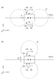
- FIG. 6 is a schematic configuration diagram of the antenna device 10A.
- FIG. 7 is a diagram illustrating an arrangement example of each antenna element. As illustrated in FIGS. 6 and 7, the antenna device 10 ⁇ / b> A differs from the antenna device 10 in the number and arrangement of antenna elements and the number of phase shifters. Specifically, the antenna device 10A further includes an antenna element 11c (third antenna element) and an antenna element 11d (fourth antenna element), and a phase shifter 12c and a phase shifter 12d.
- the antenna element 11c and the antenna element 11d are elements for transmitting and receiving VHF band radio waves. Similarly to the antenna element 11a and the antenna element 11b, the antenna element 11c and the antenna element 11d convert radio waves generated in the space during transmission or reception into the polarization component in the X-axis direction and the polarization in the Y-axis direction on the XY plane. Contains elements that can be decomposed into wave components. Specifically, the antenna element 11c and the antenna element 11d have a shape in which the portion from the feeding point of the element to the tip of the element has a length component in the X-axis direction and a length component in the Y-axis direction. ing.
- the length component in the X-axis direction and the length component in the Y-axis direction are, for example, about 1/100 wavelength to 1 wavelength.
- Examples of such an antenna element include an inverted F-type antenna, an inverted L-type antenna, a microstrip antenna, and a monopole antenna that is inclined with respect to a symmetry line.
- the antenna element 11a, the antenna element 11b, the antenna element 11c, and the antenna element 11d are inverted F-type antennas. Note that the configurations of the antenna element 11c and the antenna element 11d are the same as the configurations of the antenna element 11a and the antenna element 11b, and thus detailed description thereof is omitted.
- the antenna element 11c When the antenna device 10A functions as a transmission antenna, the antenna element 11c is fed with the third feeding phase, and the antenna element 11d is fed with the fourth feeding phase.
- the received signal of the antenna element 11c When the antenna device 10A functions as a receiving antenna, the received signal of the antenna element 11c is combined with the third combined phase, and the received signal of the antenna element 11d is combined with the fourth combined phase.
- the electric field generated when transmitting / receiving radio waves has a polarization component A3 that is a polarization component in the Y-axis direction and a polarization component that is a polarization component in the X-axis direction in the XY plane. It can be decomposed into a wave component B3.
- an electric field generated when radio waves are transmitted and received includes a polarization component A4 that is a polarization component in the Y-axis direction and a polarization component B4 that is a polarization component in the X-axis direction in the XY plane. And can be broken down.
- the antenna element 11c and the antenna element 11d when the third feeding phase (third synthesized phase) and the fourth feeding phase (fourth synthesized phase) are in phase with each other, the polarization component A3 and the polarization component A4 are stronger than each other.
- the polarization component B3 and the polarization component B4 are arranged so as to weaken each other.
- the antenna element 11c and the antenna element 11d have the polarization component A3 and the polarization component A4 when the third feeding phase (third synthesis phase) and the fourth feeding phase (fourth synthesis phase) are opposite to each other. Are arranged so as to weaken each other and the polarization component B3 and the polarization component B4 strengthen each other.
- the polarization component A3 and the polarization component A4 are line symmetric with respect to the center line C1 of the satellite 1A in the X-axis direction
- the antenna element 11c and the antenna element 11d are arranged so that the polarization component B3 and the polarization component B4 are axisymmetric with respect to the center line C1.
- the X-axis direction length component of the element of the antenna element 11c extends with the feed point 114 as a reference, and the X-axis length component of the antenna element 11d element (feed element 113).
- the length component (radiating element 111) in the Y-axis direction of the element of the antenna element 11c extends with respect to the feeding point 114, and the length component (radiating element 111) in the Y-axis direction of the element of the antenna element 11d.
- the direction extending with reference to the feeding point 114 is the same.
- the antenna element 11c and the antenna element 11d are located in substantially the same plane, and are arranged substantially symmetrically with respect to the center line C1.
- the term “substantially in the same plane” includes the case where the distance is 0.25 wavelength or less from the same plane and the same plane.
- the term “substantially line symmetric” includes complete line symmetry and a case where the position is shifted by 0.25 wavelength or less from the position of complete line symmetry.
- the distance between the antenna element 11c and the antenna element 11d is about one wavelength or less. About one wavelength is, for example, 0.25 wavelength or more and 1.5 wavelengths or less.
- the antenna component 11a and the antenna element 11c when the first feeding phase (first combined phase) and the third feeding phase (third combined phase) are in phase with each other, the antenna component 11a and the antenna element 11c have the polarization component A1 and the polarization component A3.
- the polarization component B1 and the polarization component B3 are arranged so as to weaken each other and strengthen each other.
- the antenna element 11a and the antenna element 11c have the polarization component A1 and the polarization component A3 when the first feed phase (first composite phase) and the third feed phase (third composite phase) are opposite to each other.
- the polarization component A1 and the polarization component A3 are line symmetric with respect to the center line C2 of the satellite 1A in the Y-axis direction
- the antenna element 11a and the antenna element 11c are arranged so that the polarization component B1 and the polarization component B3 are axisymmetric with respect to the center line C2.
- the X-axis length component of the element of the antenna element 11a extends with the feed point 114 as a reference, and the X-axis length component of the antenna element 11c element (feed element 113). ) Is the same as the direction in which the feed point 114 extends.
- the length component (radiating element 111) in the Y-axis direction of the element of the antenna element 11a extends with respect to the feeding point 114, and the length component (radiating element 111) in the Y-axis direction of the element of the antenna element 11c.
- the directions extending with respect to the feeding point 114 are opposite to each other.
- the antenna element 11a and the antenna element 11c are located in substantially the same plane, and are arranged substantially symmetrically with respect to the center line C2.
- the distance between the antenna element 11a and the antenna element 11c is about one wavelength or less.
- the antenna element 11b and the antenna element 11d when the second feed phase (second composite phase) and the fourth feed phase (fourth composite phase) are in phase with each other, the polarization component A2 and the polarization component A4 are weakened.
- the polarization component B2 and the polarization component B4 are arranged so as to strengthen each other.
- the antenna element 11b and the antenna element 11d have the polarization component A2 and the polarization component A4 when the second feed phase (second composite phase) and the fourth feed phase (fourth composite phase) are opposite to each other. Are arranged such that the polarization component B2 and the polarization component B4 weaken each other.
- the polarization component A2 and the polarization component A4 are axisymmetric with respect to the center line C2, and the polarization component B2
- the antenna element 11b and the antenna element 11d are arranged so that the polarization component B4 is axisymmetric with respect to the center line C2.
- the X-axis length component of the element of the antenna element 11b extends with the feed point 114 as a reference, and the X-axis length component of the antenna element 11d element (feed element 113). ) Is the same as the direction in which the feed point 114 extends. Further, the length component (radiating element 111) in the Y-axis direction of the element of the antenna element 11b extends with respect to the feeding point 114, and the length component (radiating element 111) in the Y-axis direction of the element of the antenna element 11d.
- the directions extending with respect to the feeding point 114 are opposite to each other.
- the antenna element 11b and the antenna element 11d are located in substantially the same plane and are arranged substantially symmetrically with respect to the center line C2. The distance between the antenna element 11b and the antenna element 11d is about one wavelength or less.
- the phase shifter 12c is a circuit that adjusts the third feeding phase and the third combined phase.
- the phase shifter 12c adjusts the third feed phase when the antenna device 10A functions as a transmission antenna.
- the phase shifter 12c adjusts the third combined phase.
- the phase shifter 12d is a circuit that adjusts the fourth feeding phase and the fourth combined phase.
- the phase shifter 12d adjusts the fourth feeding phase when the antenna device 10A functions as a transmission antenna.
- the phase shifter 12d adjusts the fourth combined phase.
- the distribution synthesizer 13 distributes the signal from the transceiver 14 to the antenna element 11a, the antenna element 11b, the antenna element 11c, and the antenna element 11d.
- the distribution synthesizer 13 inputs signals received by the antenna element 11a, the antenna element 11b, the antenna element 11c, and the antenna element 11d, and synthesizes these received signals.
- the transceiver 14 When the antenna device 10A functions as a transmission antenna, the transceiver 14 outputs a signal subjected to various processes such as modulation to the distribution synthesizer 13. When the antenna device 10A functions as a receiving antenna, the transceiver 14 receives the signal synthesized by the distribution synthesizer 13 and performs various processes such as demodulation.
- the control unit 15 controls the phase shifter 12a to adjust the first feeding phase, controls the phase shifter 12b to adjust the second feeding phase, and shifts the phase.
- the direction of the polarization of the antenna device 10A is controlled by adjusting the third feed phase by controlling the phase shifter 12c and adjusting the fourth feed phase by controlling the phase shifter 12d.
- the control unit 15 receives a control command from the ground station, and in accordance with the received control command, the first feeding phase of the phase shifter 12a, the second feeding phase of the phase shifter 12b, and the first feeding phase of the phase shifter 12c.
- the third feeding phase and the fourth feeding phase of the phase shifter 12d are controlled.
- the control unit 15 controls the phase shifter 12a to adjust the first combined phase, controls the phase shifter 12b to adjust the second combined phase, and shifts the phase.
- the direction of the polarization of the antenna apparatus 10A is controlled by adjusting the third combined phase by controlling the device 12c, and adjusting the fourth combined phase by controlling the phase shifter 12d.
- the control unit 15 receives a control command from the ground station, and according to the received control command, the first combined phase of the phase shifter 12a, the second combined phase of the phase shifter 12b, and the first of the phase shifter 12c.
- the third synthesized phase and the fourth synthesized phase of the phase shifter 12d are controlled.
- the antenna device 10A functions as a transmission antenna and the case where the antenna device 10A functions as a reception antenna are reversible.
- the case where the antenna device 10A functions as a transmission antenna will be described using the feeding phase, but the same holds true when the antenna device 10A functions as a reception antenna.
- FIG. 8 is a diagram for explaining control for directing the main polarization direction in the Y-axis direction.
- 8A is a diagram for explaining an example of the polarization component of each antenna element
- FIG. 8B is the directivity of the antenna device 10A when the main polarization direction is in the Y-axis direction. It is a figure which shows an example of a pattern.
- FIG. 8B shows a directivity pattern when the earth is viewed from the satellite 1A, and the intersection of the X axis and the Y axis indicates directly below the satellite 1A.
- the first feed phase is set to 0 ° by the phase shifter 12a
- the second feed phase is set to 0 ° by the phase shifter 12b
- the third feed phase is set to 180 ° by the phase shifter 12c.
- the fourth feed phase is set to 180 ° by the phase shifter 12d.
- the polarization component A1, the polarization component A2, the polarization component A3, and the polarization component A4 are in phase with each other.
- the polarization component A in the direction is the sum of the polarization component A1, the polarization component A2, the polarization component A3, and the polarization component A4.
- the polarization component B1 and the polarization component B2 are opposite in phase, and the distance from the antenna element 11a to the plane P and the distance from the antenna element 11b to the plane P are equal to each other.
- the components B2 cancel each other in the plane P.
- the polarization component B3 and the polarization component B4 are opposite in phase, and the distance from the antenna element 11c to the plane P and the distance from the antenna element 11d to the plane P are equal to each other. Components B4 cancel each other in the plane P.
- the main polarization direction of the antenna device 10A that is, the main polarization direction of the satellite 1A is the Y-axis direction (+ Y direction).
- the polarization of the ground station is vertical polarization and the earth is in the + Z direction
- the polarization of the satellite 1A coincides with the polarization of the ground station in the Y-axis direction. For this reason, the radio wave reception sensitivity in the Y-axis direction increases.
- the radio wave reception sensitivity in the X-axis direction is reduced. As a result, the directivity pattern shown in FIG. 8B is obtained.
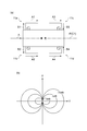
- FIG. 9 is a diagram for explaining control for directing the main polarization direction in the X-axis direction.
- 9A is a diagram for explaining another example of the polarization component of each antenna element
- FIG. 9B is a diagram of the antenna device 10A when the main polarization direction is directed in the X-axis direction. It is a figure which shows an example of a directivity pattern.
- FIG. 9B shows a directivity pattern when the earth is viewed from the satellite 1A, and the intersection of the X axis and the Y axis indicates directly below the satellite 1A.
- the first feed phase is set to 0 ° by the phase shifter 12a
- the second feed phase is set to 180 ° by the phase shifter 12b
- the third feed phase is set to 0 ° by the phase shifter 12c.
- the fourth feed phase is set to 180 ° by the phase shifter 12d.
- the polarization component A1 and the polarization component A2 are opposite in phase, and the distance from the antenna element 11a to the plane P and the distance from the antenna element 11b to the plane P Are equal to each other, the polarization component A1 and the polarization component A2 cancel each other in the plane P.
- the polarization component A3 and the polarization component A4 are opposite in phase, and the distance from the antenna element 11c to the plane P and the distance from the antenna element 11d to the plane P are equal to each other.
- the components A4 cancel each other in the plane P.
- the polarization component B1 the polarization component B2, the polarization component B3, and the polarization component B4 are in phase with each other, in the plane P
- the polarization component B in the X-axis direction of the combined wave is the polarization component B1
- the main polarization direction of the antenna device 10A that is, the main polarization direction of the satellite 1A is the X-axis direction (+ X direction).
- the polarization of the ground station is vertical polarization and the earth is in the + Z direction
- the polarization of the satellite 1A coincides with the polarization of the ground station in the X-axis direction. For this reason, the radio wave reception sensitivity in the X-axis direction increases.
- the radio wave reception sensitivity in the Y-axis direction is reduced. As a result, the directivity pattern shown in FIG. 9B is obtained.
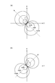
- FIG. 10 is a diagram illustrating an example of a directivity pattern of the antenna device 10A when the main polarization direction is directed in a direction other than the X-axis direction and the Y-axis direction.
- FIG. 10A shows a directivity pattern when the earth is viewed from the satellite 1A, and the intersection of the X axis and the Y axis indicates directly below the satellite 1A.
- the first feed phase is set to ⁇ by the phase shifter 12a
- the second feed phase is set to 180 ° by the phase shifter 12b
- the third feed phase is set to 0 ° by the phase shifter 12c.
- the fourth feeding phase is set to 180 ° + ⁇ by the phase shifter 12d.
- the first feeding phase and the fourth feeding phase are larger by ⁇ than the example shown in FIG. That is, the first feeding phase and the fourth feeding phase are set in opposite phases, and the second feeding phase and the third feeding phase are set in opposite phases.
- ⁇ 0 °
- the polarization component in the + X direction remains on the plane P.
- the + X direction Changes to a state in which the polarization component of ⁇ and the polarization component in the ⁇ Y direction exist.
- the main polarization of the antenna device 10A is tilted from the + X direction to the ⁇ Y side according to the size of ⁇ .
- the angle ⁇ formed between the main polarization direction of the antenna device 10A and the + X direction is ( ⁇ / 2).
- a directivity pattern obtained by rotating the directivity pattern shown in FIG. 9B by ⁇ / 2 around the intersection of the X axis and the Y axis to the ⁇ Y side is obtained.
- a portion having strong directivity is generated in a direction inclined ( ⁇ / 2) from the + X direction to the ⁇ Y side.
- FIG. 10 is a diagram illustrating another example of the directivity pattern of the antenna device 10A when the main polarization direction is directed to a direction other than the X-axis direction and the Y-axis direction.
- FIG. 10B shows a directivity pattern when the earth is viewed from the satellite 1A, and the intersection of the X axis and the Y axis indicates directly below the satellite 1A.
- the first feed phase is set to ⁇ by the phase shifter 12a
- the second feed phase is set to 180 ° by the phase shifter 12b
- the third feed phase is set to 0 ° by the phase shifter 12c.
- the fourth feed phase is set to 180 ° ⁇ by the phase shifter 12d.
- the first feeding phase and the fourth feeding phase are smaller by ⁇ than the example shown in FIG.
- ⁇ 0 °
- only the polarization component in the + X direction remains on the plane P.
- ⁇ 0 °
- the polarization component in the + Y direction gradually increases, The state changes to a state in which a polarization component and a polarization component in the + Y direction exist.
- the polarization component in the + X direction and the polarization component in the + Y direction are combined, a polarization component in one direction on the XY plane is obtained.
- the ratio between the magnitude of the polarization component in the + X direction and the magnitude of the polarization component in the + Y direction changes, so the direction of polarization changes. That is, if ⁇ is increased from 0 °, the magnitude of the polarization component in the + X direction is reduced and the magnitude of the polarization component in the + Y direction is increased, so that the polarization direction is inclined (rotated) to the + Y side. . As a result, the main polarization of the antenna device 10A is tilted from the + X direction to the + Y side according to the size of ⁇ .
- the angle ⁇ formed between the main polarization direction of the antenna device 10A and the + X direction is ( ⁇ / 2).
- a directivity pattern obtained by rotating the directivity pattern shown in FIG. 9B to the + Y side about the intersection of the X axis and the Y axis by ⁇ / 2 is obtained.
- a portion having strong directivity is generated at a position inclined ( ⁇ / 2) from the + X direction to the + Y side.
- the first power supply phase and the fourth power supply phase are variably controlled, the first power supply phase and the fourth power supply phase are opposite to each other, and the second power supply phase and the third power supply phase are mutually opposite. If the phase is reversed, the first power supply phase, the second power supply phase, the third power supply phase, and the fourth power supply phase may be variably controlled. At this time, the phase difference of the first power supply phase with respect to the third power supply phase is equal to the phase difference of the fourth power supply phase with respect to the second power supply phase.
- this phase difference corresponds to the above-mentioned ⁇ and the phase difference ⁇ is a positive value
- the directivity pattern shown in FIG. 9B is obtained on the XY plane according to the phase difference ⁇ .
- the directivity pattern shown in FIG. 9B corresponds to the intersection of the X axis and the Y axis in the XY plane according to the phase difference ⁇ .
- FIG. 11A is a diagram showing an example of the directivity pattern of the antenna device 10A when the directivity is tilted in the ⁇ Y direction.
- FIG. 11A shows a directivity pattern when the earth is viewed from the satellite 1A, and the intersection of the X axis and the Y axis indicates directly below the satellite 1A.
- the first feed phase is set to 0 ° by the phase shifter 12a
- the second feed phase is set to 180 ° by the phase shifter 12b
- the third feed phase is set to ⁇ by the phase shifter 12c.
- the fourth feeding phase is set to 180 ° + ⁇ by the phase shifter 12d.
- the main polarization direction of the antenna device 10A is the X axis.
- Direction (+ X direction) the third feed phase is ⁇ larger than the first feed phase
- the fourth feed phase is ⁇ larger than the second feed phase.
- the phases of the radio waves from the antenna element 11c and the antenna element 11d advance by + ⁇ with respect to the radio waves from the antenna element 11a and the antenna element 11b.
- the distance from the antenna element 11c and the antenna element 11d is larger than the distance from the antenna element 11a and the antenna element 11b.
- the phase of the radio wave from the antenna element 11c and the antenna element 11d is delayed with respect to the phase of the radio wave.
- the phase difference due to the difference in distance becomes ⁇ , and cancels out the phase difference + ⁇ due to the feeding, thereby the antenna element 11a and the antenna element Since there is no phase difference between the radio wave from 11b and the radio waves from the antenna element 11c and the antenna element 11d, the directivity is directed to the direction L1 and the direction L2.
- the + X direction pattern of the directivity pattern shown in (b) of FIG. 9 is inclined in the direction L1 by tilting the angle ⁇ 1 in the ⁇ Y direction, and the ⁇ X direction of the directivity pattern shown in (b) of FIG. The pattern is inclined in the ⁇ Y direction by an angle ⁇ 2 and directed in the direction L2.
- the directivity of the antenna device 10A is tilted in the ⁇ Y direction in proportion to the value of ⁇ .
- FIG. 11B is a diagram illustrating an example of the directivity pattern of the antenna device 10A when the directivity is tilted in the + Y direction.
- FIG. 11B shows a directivity pattern when the earth is viewed from the satellite 1A, and the intersection of the X axis and the Y axis indicates directly below the satellite 1A.
- the first feed phase is set to 0 ° by the phase shifter 12a
- the second feed phase is set to 180 ° by the phase shifter 12b
- the third feed phase is set to ⁇ by the phase shifter 12c.
- the fourth feed phase is set to 180 ° ⁇ by the phase shifter 12d.
- the main polarization direction of the antenna device 10A is the X axis.
- the first feed phase is ⁇ larger than the third feed phase
- the second feed phase is ⁇ greater than the fourth feed phase.
- the phases of the radio waves from the antenna element 11c and the antenna element 11d are delayed by - ⁇ with respect to the radio waves from the antenna element 11a and the antenna element 11b.
- the distance from the antenna element 11c and the antenna element 11d is smaller than the distance from the antenna element 11a and the antenna element 11b.
- the phase of the radio wave from the antenna element 11c and the antenna element 11d advances with respect to the phase of the radio wave.
- the phase difference due to this difference in distance becomes + ⁇ , and cancels out the phase difference ⁇ due to the power feeding, so that the antenna element 11a and the antenna element Since there is no phase difference between the radio wave from 11b and the radio waves from the antenna element 11c and the antenna element 11d, the directivity is directed to the direction L3 and the direction L4.
- the third feed phase and the fourth feed phase are variably controlled, but the first feed phase and the second feed phase are opposite to each other, and the third feed phase and the fourth feed phase are mutually opposite. If the phase is reversed, the first power supply phase, the second power supply phase, the third power supply phase, and the fourth power supply phase may be variably controlled. At this time, the phase difference of the third power supply phase with respect to the first power supply phase is equal to the phase difference of the fourth power supply phase with respect to the second power supply phase.
- this phase difference corresponds to the above-mentioned ⁇ and the phase difference ⁇ is a positive value
- the directivity pattern shown in FIG. 9B is tilted in the ⁇ Y direction according to the phase difference ⁇ . Is done.
- the phase difference ⁇ is a negative value
- the directivity pattern shown in FIG. 9B is tilted in the + Y direction according to the phase difference ⁇ .
- FIG. 12 is a diagram illustrating an example of the directivity pattern of the antenna device 10A when the directivity is tilted in the + X direction.
- FIG. 12 shows a directivity pattern when the earth is viewed from the satellite 1A, and the intersection of the X axis and the Y axis indicates directly below the satellite 1A.
- the first feed phase is set to 0 ° by the phase shifter 12a
- the second feed phase is set to 180 ° + ⁇ by the phase shifter 12b
- the third feed phase is set to 0 ° by the phase shifter 12c.
- the fourth power feeding phase is set to 180 ° + ⁇ by the phase shifter 12d.
- the first feeding phase and the third feeding phase are in phase with each other, and the second feeding phase and the fourth feeding phase are in phase with each other. Furthermore, the phase difference between the first power supply phase and the second power supply phase is 180 ° + ⁇ , and the phase difference between the third power supply phase and the fourth power supply phase is 180 ° + ⁇ .
- the polarization component is strengthened in the X-axis direction. For this reason, the main polarization direction of the antenna device 10A is the X-axis direction (+ X direction). Since the second feeding phase and the fourth feeding phase are + ⁇ larger than the example shown in FIG.
- the directivity of the antenna device 10A is tilted in the + X direction to cancel the phase difference + ⁇ due to the feeding. Is done.
- ⁇ is gradually increased from 0 °, as shown in FIG.
- the directivity of the antenna device 10A is tilted in the + X direction in proportion to the value.
- the first power supply phase and the third power supply phase are in phase with each other, and the second power supply phase and the fourth power supply phase are in phase with each other. If so, the first feed phase, the second feed phase, the third feed phase, and the fourth feed phase may be variably controlled.
- the phase difference of the second feed phase with respect to the opposite phase of the first feed phase is equal to the phase difference of the fourth feed phase with respect to the opposite phase of the third feed phase.
- the antenna device 10A when the first feed phase (first combined phase) and the second feed phase (second combined phase) are in phase with each other, the polarization component A1 of the antenna element 11a. And the polarization component A2 of the antenna element 11b strengthen each other, and the polarization component B1 of the antenna element 11a and the polarization component B2 of the antenna element 11b weaken each other.
- the polarization component A3 of the antenna element 11c and the polarization component A4 of the antenna element 11d And the polarization component B3 of the antenna element 11c and the polarization component B4 of the antenna element 11d are mutually weakened.
- the first feeding phase (first combined phase) and the third feeding phase (third combined phase) are opposite to each other, the polarization component A1 of the antenna element 11a and the polarization component A3 of the antenna element 11c And the polarization component B1 of the antenna element 11a and the polarization component B3 of the antenna element 11c weaken each other.
- the second feed phase (second composite phase) and the fourth feed phase (fourth composite phase) are opposite to each other, the polarization component A2 of the antenna element 11b and the polarization component A4 of the antenna element 11d And the polarization component B2 of the antenna element 11b and the polarization component B4 of the antenna element 11d are mutually weakened. Therefore, the first feeding phase (first synthesized phase) and the second feeding phase (second synthesized phase) are in phase with each other, and the third feeding phase (third synthesized phase) and the fourth feeding phase (fourth synthesized phase).
- the main polarization direction of the antenna device 10A can be set to the Y-axis direction.
- the polarization component A1 of the antenna element 11a and the polarization component A2 of the antenna element 11b are The polarization component B1 of the antenna element 11a and the polarization component B2 of the antenna element 11b strengthen each other.
- the polarization component A3 of the antenna element 11c and the polarization component of the antenna element 11d A4 weakens each other, and the polarization component B3 of the antenna element 11c and the polarization component B4 of the antenna element 11d strengthen each other.
- the polarization component A1 of the antenna element 11a and the polarization component A3 of the antenna element 11c Weaken each other, and the polarization component B1 of the antenna element 11a and the polarization component B3 of the antenna element 11c strengthen each other.
- the second feed phase (second composite phase) and the fourth feed phase (fourth composite phase) are in phase with each other, the polarization component A2 of the antenna element 11b and the polarization component A4 of the antenna element 11d Weaken each other, and the polarization component B2 of the antenna element 11b and the polarization component B4 of the antenna element 11d strengthen each other.
- the first feeding phase (first synthesized phase) and the second feeding phase (second synthesized phase) are opposite to each other, and the third feeding phase (third synthesized phase) and the fourth feeding phase (fourth synthesized phase).
- the first feed phase (first composite phase) and the third feed phase (third composite phase) are in phase with each other, the second feed phase (second composite phase) and the fourth feed phase (first 4), the main polarization direction of the antenna device 10A can be set to the X-axis direction.
- first feed phase (first composite phase) and the fourth feed phase (fourth composite phase) are adjusted to be opposite to each other, and the second feed phase (second composite phase) and the third feed phase are adjusted.
- (Third synthesized phase) may be adjusted so as to be in opposite phases to each other.
- Is equal to the phase difference ⁇ .
- the ratio between the magnitude of the polarization component in the X-axis direction and the magnitude of the polarization component in the Y-axis direction changes.
- the angle formed by the main polarization direction of the antenna device 10A and the X-axis direction can be adjusted to an angle corresponding to the phase difference ⁇ .
- the main polarization direction of the antenna device 10A can be set to a desired direction on the XY plane. That is, according to the antenna device 10A, the direction of polarization of the antenna device 10A can be controlled in a desired direction in a plane including the antenna element 11a, the antenna element 11b, the antenna element 11c, and the antenna element 11d. .
- the communicable area can be controlled in an intended direction, and congestion of signals received by the satellite 1A can be prevented.
- the antenna device 10A since the antenna device 10A only needs to include the antenna element 11a, the antenna element 11b, the antenna element 11c, and the antenna element 11d as antenna elements, the number of antenna elements can be reduced as compared with the phased array antenna. As a result, it is possible to reduce the size and weight without reducing the communication efficiency.
- first feeding phase (first synthesized phase) and the second feeding phase (second synthesized phase) are adjusted to be opposite to each other, and the third feeding phase (third synthesized phase) and the fourth feeding phase (fourth synthesized phase) are adjusted.
- Phase) can be adjusted to be out of phase with each other.
- the main polarization direction of the antenna device 10A is the X-axis direction (+ X direction).
- the phase difference ⁇ of the third feed phase (third composite phase) with respect to the first feed phase (first composite phase) and the fourth feed phase (fourth composite phase) with respect to the second feed phase (second composite phase) Are equal to each other.
- the directivity of the antenna device 10A tilts in a direction that cancels out the phase difference ⁇ . Since the phase difference ⁇ is generated in the Y-axis direction, the directivity directed in the X-axis direction can be tilted in the Y-axis direction according to the phase difference ⁇ .
- first feeding phase (first synthesized phase) and the third feeding phase (third synthesized phase) are adjusted to be in phase with each other, and the second feeding phase (second synthesized phase) and the fourth feeding phase (fourth synthesized phase) are adjusted.
- the first power supply phase (first composite phase) and the third power supply phase (third composite phase) are in phase with each other, and the second power supply phase (second composite phase) and the fourth power supply phase (fourth composite phase).
- the polarization component is strengthened in the X-axis direction. Therefore, the main polarization direction of the antenna device 10A is the X-axis direction.
- the phase difference becomes equal to each other, and the phase difference can be expressed as 180 ° + ⁇ .
- the directivity of the antenna device 10A tilts in a direction to cancel this ⁇ . Since the phase difference of 180 ° + ⁇ occurs in the X-axis direction, it is possible to tilt the directivity directed evenly in the + X direction and the ⁇ X direction to either the + X direction or the ⁇ X direction according to ⁇ . Become.
- the polarization direction of the satellite 1A is adjusted so that the polarization of the radio wave transmitted from the ship existing in the ship dense area is orthogonal to the polarization of the satellite 1A (antenna device 10A). Is done. Thereby, the sensitivity of the antenna device 10A can be lowered with respect to the ship dense area, and the number of AIS signals received by the satellite 1A can be reduced. As a result, the AIS signal reception rate can be improved.
- an inverted F-type antenna can be used as the antenna element 11a, antenna element 11b, antenna element 11c, and antenna element 11d. For this reason, the antenna element 11a, the antenna element 11b, the antenna element 11c, and the antenna element 11d can be reduced in size and weight, and the antenna device 10A can be further reduced in size and weight. As a result, the mountability of the antenna device 10A on the satellite 1A is improved.
- the antenna devices 10 and 10A are mounted on a satellite, but are not limited thereto.
- the antenna devices 10 and 10A may be mounted on a flying body such as a small UAV (Unmanned Aerial Vehicle) and a small stratosphere platform.
- the antenna device 10 includes two antenna elements, and the antenna device 10A includes four antenna elements, but is not limited thereto.
- the antenna devices 10 and 10A may include a further antenna element with a pair of antenna elements arranged symmetrically with respect to the center line C1 as a unit. In this case, as the number of antenna elements increases, the directivity of the antenna devices 10 and 10A can be sharpened.
- the antenna devices 10 and 10A transmit and receive VHF band radio waves, they may only transmit VHF band radio waves or may only receive VHF band radio waves.
- phase shifter 12a, the phase shifter 12b, the phase shifter 12c, and the phase shifter 12d may be configured as one phase shifter 12.
- the antenna devices 10 and 10A may not include the control unit 15.
- control unit 15 may dynamically control the direction of polarization of the antenna devices 10 and 10A according to the position and attitude of the satellites 1 and 1A.
- control unit 15 may dynamically control the direction of polarization of the antenna devices 10 and 10A so that the sensitivity of the ship dense area decreases according to the position and attitude of the satellites 1 and 1A.
Landscapes
- Physics & Mathematics (AREA)
- Engineering & Computer Science (AREA)
- Astronomy & Astrophysics (AREA)
- Aviation & Aerospace Engineering (AREA)
- General Physics & Mathematics (AREA)
- Remote Sensing (AREA)
- Variable-Direction Aerials And Aerial Arrays (AREA)
- Waveguide Aerials (AREA)
- Details Of Aerials (AREA)
Abstract
アンテナ装置は、VHF帯の電波を送受信するアンテナ装置であって、給電点から先端までの部分が、第1方向の長さ成分と、第1方向と直交する第2方向の長さ成分と、を有する形状を呈するエレメントをそれぞれ含む第1アンテナ素子及び第2アンテナ素子と、第1アンテナ素子の第1給電位相及び第2アンテナ素子の第2給電位相、または、第1アンテナ素子の第1合成位相及び第2アンテナ素子の第2合成位相を調整することによって、アンテナ装置の偏波の向きを制御する移相器と、を備える。第1アンテナ素子及び第2アンテナ素子は、第1給電位相及び第2給電位相が互いに同相であるか、または、第1合成位相及び第2合成位相が互いに同相である場合、第1方向において偏波成分が互いに強め合い、第2方向において偏波成分が互いに弱め合うように配置される。
Description
本開示は、アンテナ装置に関する。本出願は、2015年1月5日に提出された日本特許出願第2015-000250号に基づいており、それに対して優先権の利益を主張するものであり、その内容全体は、参照されることによって本出願に援用される。
衛星等の飛翔体に搭載されるアンテナ装置では、通信効率を向上するためにアンテナの指向性が制御される。例えば、特許文献1には、複数のアンテナ素子を備えるフェイズドアレイアンテナを搭載し、指向方向エラーに応じて個々のアンテナ素子の位相シフタ(移相器)を制御することによって、アンテナの指向性を制御する衛星が記載されている。
VHF帯の電波の波長は数メートルであり比較的大きいので、アンテナ素子も波長に準じて大きくなる。このため、特許文献1に記載のフェイズドアレイアンテナをVHF帯の電波の送受信に用いる場合、フェイズドアレイアンテナは複数のアンテナ素子を備えていることから、各アンテナ素子が大型化する。これよって、アンテナ装置の設置スペースが格段に大きくなり、アンテナ装置の重量も大きくなる。したがって、より小型軽量化する要求の強い衛星等の飛翔体への適用の障害となることがあった。
一方、衛星等の飛翔体に搭載されるVHF帯のアンテナとして、比較的小型軽量である無指向性のモノポールアンテナ等が用いられることがある。しかしながら、衛星等に無指向性のアンテナを搭載した場合、地上の広範囲なエリアが通信可能エリアとなる。このため、地上の無線局が多数存在し同時に電波を送信している状況において、飛翔体に到来する信号が重なり合って輻輳を生じて受信率が低下し、その結果、通信効率が低下するおそれがある。
本開示は、通信効率を低下させることなく小型化及び軽量化が可能なアンテナ装置を説明する。
本開示の一態様に係るアンテナ装置は、飛翔体に搭載され、VHF帯の電波を送受信するアンテナ装置である。このアンテナ装置は、給電点から先端までの部分が、第1方向の長さ成分と、第1方向と直交する第2方向の長さ成分と、を有する形状を呈するエレメントを含む第1アンテナ素子と、給電点から先端までの部分が、第1方向の長さ成分と、第2方向の長さ成分と、を有する形状を呈するエレメントを含む第2アンテナ素子と、第1アンテナ素子の第1給電位相及び第2アンテナ素子の第2給電位相、または、第1アンテナ素子の第1合成位相及び第2アンテナ素子の第2合成位相を調整することによって、アンテナ装置の偏波の向きを制御する移相器と、を備える。第1アンテナ素子及び第2アンテナ素子は、第1給電位相及び第2給電位相が互いに同相であるか、または、第1合成位相及び第2合成位相が互いに同相である場合、第1方向において偏波成分が互いに強め合い、第2方向において偏波成分が互いに弱め合うように配置される。
本開示の態様によれば、通信効率を低下させることなく、アンテナ装置の小型化及び軽量化が可能となる。
[1]実施形態の概要
本開示の一態様に係るアンテナ装置は、飛翔体に搭載され、VHF帯の電波を送受信するアンテナ装置である。このアンテナ装置は、給電点から先端までの部分が、第1方向の長さ成分と、第1方向と直交する第2方向の長さ成分と、を有する形状を呈するエレメントを含む第1アンテナ素子と、給電点から先端までの部分が、第1方向の長さ成分と、第2方向の長さ成分と、を有する形状を呈するエレメントを含む第2アンテナ素子と、第1アンテナ素子の第1給電位相及び第2アンテナ素子の第2給電位相、または、第1アンテナ素子の第1合成位相及び第2アンテナ素子の第2合成位相を調整することによって、アンテナ装置の偏波の向きを制御する移相器と、を備える。第1アンテナ素子及び第2アンテナ素子は、第1給電位相及び第2給電位相が互いに同相であるか、または、第1合成位相及び第2合成位相が互いに同相である場合、第1方向において偏波成分が互いに強め合い、第2方向において偏波成分が互いに弱め合うように配置される。
本開示の一態様に係るアンテナ装置は、飛翔体に搭載され、VHF帯の電波を送受信するアンテナ装置である。このアンテナ装置は、給電点から先端までの部分が、第1方向の長さ成分と、第1方向と直交する第2方向の長さ成分と、を有する形状を呈するエレメントを含む第1アンテナ素子と、給電点から先端までの部分が、第1方向の長さ成分と、第2方向の長さ成分と、を有する形状を呈するエレメントを含む第2アンテナ素子と、第1アンテナ素子の第1給電位相及び第2アンテナ素子の第2給電位相、または、第1アンテナ素子の第1合成位相及び第2アンテナ素子の第2合成位相を調整することによって、アンテナ装置の偏波の向きを制御する移相器と、を備える。第1アンテナ素子及び第2アンテナ素子は、第1給電位相及び第2給電位相が互いに同相であるか、または、第1合成位相及び第2合成位相が互いに同相である場合、第1方向において偏波成分が互いに強め合い、第2方向において偏波成分が互いに弱め合うように配置される。
このアンテナ装置によれば、第1給電位相及び第2給電位相が互いに同相である場合、または、第1合成位相及び第2合成位相が互いに同相である場合には、第1アンテナ素子の第1方向の偏波成分と第2アンテナ素子の第1方向の偏波成分とが互いに強め合い、第1アンテナ素子の第2方向の偏波成分と第2アンテナ素子の第2方向の偏波成分とが互いに弱め合うので、アンテナ装置の主たる偏波の向きが第1方向となる。言い換えると、第1給電位相及び第2給電位相、または、第1合成位相及び第2合成位相が互いに逆相である場合には、第1アンテナ素子の第1方向の偏波成分と第2アンテナ素子の第1方向の偏波成分とが互いに弱め合い、第1アンテナ素子の第2方向の偏波成分と第2アンテナ素子の第2方向の偏波成分とが互いに強め合うので、アンテナ装置の主たる偏波の向きが第2方向となる。このため、第1アンテナ素子の第1給電位相及び第2アンテナ素子の第2給電位相、または、第1アンテナ素子の第1合成位相及び第2アンテナ素子の第2合成位相を調整することによって、アンテナ装置の偏波の向きを制御することが可能となる。これにより、通信可能なエリアを意図する向きに制御することができ、衛星によって受信される信号の輻輳を防止することが可能となる。例えば、輻輳エリアが地球上に偏在している場合、その輻輳エリアの信号を避けるような意図を持ったアンテナパターンとすることが可能となる。また、アンテナ装置は第1アンテナ素子と第2アンテナ素子とを備えればよいので、フェイズドアレイアンテナと比較してアンテナ素子の数を減らすことができる。その結果、通信効率を低下させることなく、小型化及び軽量化が可能となる。
移相器は、第1給電位相及び第2給電位相を互いに同相もしくは逆相となるように調整するか、または、第1合成位相及び第2合成位相を互いに同相もしくは逆相となるように調整してもよい。第1給電位相(第1合成位相)及び第2給電位相(第2合成位相)を互いに同相とすることによって、アンテナ装置の主たる偏波の向きを第1方向とすることができる。また、第1給電位相(第1合成位相)及び第2給電位相(第2合成位相)を互いに逆相とすることによって、アンテナ装置の主たる偏波の向きを第2方向とすることができる。このように、アンテナ装置の主たる偏波の向きを、直交する第1方向及び第2方向のいずれかに切り替えることが可能となる。
第1アンテナ素子及び第2アンテナ素子は、逆F型アンテナであってもよい。逆F型アンテナの1素子当たりのサイズは、例えば、0.25波長×0.05波長×0.01波長程度である。このため、第1アンテナ素子及び第2アンテナ素子を小型化及び軽量化することができ、アンテナ装置のさらなる小型化及び軽量化が可能となる。
本開示の別の態様に係るアンテナ装置は、給電点から先端までの部分が、第1方向の長さ成分と、第2方向の長さ成分と、を有する形状を呈するエレメントを含む第3アンテナ素子と、給電点から先端までの部分が、第1方向の長さ成分と、第2方向の長さ成分と、を有する形状を呈するエレメントを含む第4アンテナ素子と、をさらに備えてもよい。移相器は、第3アンテナ素子の第3給電位相及び第4アンテナ素子の第4給電位相、または、第3アンテナ素子の第3合成位相及び第4アンテナ素子の第4合成位相をさらに調整することによって、偏波の向きを制御してもよい。第3アンテナ素子及び第4アンテナ素子は、第3給電位相及び第4給電位相が互いに同相であるか、または、第3合成位相及び第4合成位相が互いに同相である場合、第1方向において偏波成分が互いに強め合い、第2方向において偏波成分が互いに弱め合うように配置されてもよい。第1アンテナ素子及び第3アンテナ素子は、第1給電位相及び第3給電位相が互いに逆相であるか、または、第1合成位相及び第3合成位相が互いに逆相である場合、第1方向において偏波成分が互いに強め合い、第2方向において偏波成分が互いに弱め合うように配置されてもよい。第2アンテナ素子及び第4アンテナ素子は、第2給電位相及び第4給電位相が互いに逆相であるか、または、第2合成位相及び第4合成位相が互いに逆相である場合、第1方向において偏波成分が互いに強め合い、第2方向において偏波成分が互いに弱め合うように配置されてもよい。
このアンテナ装置によれば、例えば、第1給電位相(第1合成位相)及び第2給電位相(第2合成位相)、並びに、第3給電位相(第3合成位相)及び第4給電位相(第4合成位相)を互いに同相とし、第1給電位相(第1合成位相)及び第3給電位相(第3合成位相)、並びに、第2給電位相(第2合成位相)及び第4給電位相(第4合成位相)を互いに逆相とすることによって、アンテナ装置の主たる偏波の向きを第1方向とすることができる。また、このアンテナ装置によれば、例えば、第1給電位相(第1合成位相)及び第2給電位相(第2合成位相)、並びに、第3給電位相(第3合成位相)及び第4給電位相(第4合成位相)を互いに逆相とし、第1給電位相(第1合成位相)及び第3給電位相(第3合成位相)、並びに、第2給電位相(第2合成位相)及び第4給電位相(第4合成位相)を互いに同相とすることによって、アンテナ装置の主たる偏波の向きを第2方向とすることができる。さらに、例えば、第3給電位相(第3合成位相)に対する第1給電位相(第1合成位相)の位相差と、第2給電位相(第2合成位相)に対する第4給電位相(第4合成位相)の位相差とを等しくなるように調整することによって、位相差に応じて第1方向の偏波成分の大きさと第2方向の偏波成分の大きさとの比率が変化する。このため、アンテナ装置の主たる偏波の向きと第1方向とが成す角度を調整することができ、アンテナ装置の偏波の向きを所望の方向に制御することが可能となる。これにより、通信可能なエリアを意図する向きに制御することができ、衛星によって受信される信号の輻輳を防止することが可能となる。また、アンテナ装置は第1アンテナ素子と第2アンテナ素子と第3アンテナ素子と第4アンテナ素子とを備えればよいので、フェイズドアレイアンテナと比較してアンテナ素子の数を減らすことができる。その結果、通信効率を低下させることなく、小型化及び軽量化が可能となる。
移相器は、第1給電位相及び第4給電位相を互いに逆相となるように調整するとともに、第2給電位相及び第3給電位相を互いに逆相となるように調整するか、または、第1合成位相及び第4合成位相を互いに逆相となるように調整するとともに、第2合成位相及び第3合成位相を互いに逆相となるように調整してもよい。この場合、第3給電位相(第3合成位相)に対する第1給電位相(第1合成位相)の位相差は、第2給電位相(第2合成位相)に対する第4給電位相(第4合成位相)の位相差と等しくなる。この位相差に応じて、第1方向の偏波成分の大きさと第2方向の偏波成分の大きさとの比率が変化する。このため、アンテナ装置の主たる偏波の向きと第1方向とが成す角度を調整することが可能となる。その結果、アンテナ装置の主たる偏波の向きを、第1方向及び第2方向によって規定される平面において所望の方向とすることが可能となる。
移相器は、第1給電位相及び第2給電位相を互いに逆相となるように調整するとともに、第3給電位相及び第4給電位相を互いに逆相となるように調整するか、または、第1合成位相及び第2合成位相を互いに逆相となるように調整するとともに、第3合成位相及び第4合成位相を互いに逆相となるように調整してもよい。この場合、第1給電位相(第1合成位相)に対する第3給電位相(第1合成位相)の位相差は、第2給電位相(第2合成位相)に対する第4給電位相(第4合成位相)の位相差と等しくなる。このとき、アンテナ装置の指向性は、この位相差を打ち消す方向にチルトする。位相差は第1方向に生じるので、この位相差によって、アンテナ装置の指向性を、第1方向にチルトさせる(寄せる)ことが可能となる。
移相器は、第1給電位相及び第3給電位相を互いに同相となるように調整するとともに、第2給電位相及び第4給電位相を互いに同相となるように調整するか、または、第1合成位相及び第3合成位相を互いに同相となるように調整するとともに、第2合成位相及び第4合成位相を互いに同相となるように調整してもよい。この場合、第1給電位相(第1合成位相)及び第3給電位相(第3合成位相)が互いに同相であり、第2給電位相(第2合成位相)及び第4給電位相(第4合成位相)が互いに同相であるので、第2方向において偏波成分が強められる。このため、アンテナ装置の指向性は第2方向に向く。そして、第1給電位相(第1合成位相)の逆相に対する第2給電位相(第2合成位相)の位相差は、第3給電位相(第3合成位相)の逆相に対する第4給電位相(第4合成位相)の位相差と等しくなる。このとき、アンテナ装置の指向性は、この位相差を打ち消す方向にチルトする。位相差は、第2方向に生じるので、この位相差によって、アンテナ装置の指向性を、第2方向にチルトさせることが可能となる。
第3アンテナ素子及び第4アンテナ素子は、逆F型アンテナであってもよい。逆F型アンテナの1素子当たりのサイズは、例えば、0.25波長×0.05波長×0.01波長程度である。このため、第3アンテナ素子及び第4アンテナ素子を小型化及び軽量化することができ、アンテナ装置のさらなる小型化及び軽量化が可能となる。
VHF帯の電波はAIS信号を含んでもよい。移相器は、船舶密集域の感度が低下するように偏波の向きを制御してもよい。沿岸域には、複数の船舶の航路が設定されることがあるので、船舶が密集する船舶密集域となることがある。衛星等の飛翔体に搭載したアンテナ装置を用いて、船舶からのAIS信号を受信する場合、このような海域では、複数の船舶からAIS信号が送信されるので、AIS信号が輻輳を生じ、AIS信号の受信率が低下するおそれがある。このため、船舶密集域の感度が低下するようにアンテナ装置の偏波の向きを制御することによって、アンテナ装置に到来するAIS信号の数を減らすことができ、AIS信号の受信率を改善することが可能となる。
[2]実施形態の例示
以下、本開示の実施形態について、図面を参照しながら説明する。なお、図面の説明において同一要素には同一符号を付し、重複する説明は省略する。
以下、本開示の実施形態について、図面を参照しながら説明する。なお、図面の説明において同一要素には同一符号を付し、重複する説明は省略する。
(第1実施形態)
図1は、第1実施形態に係るアンテナ装置を搭載した衛星の概略構成図である。衛星1は、例えば、重量が200kg以下であり、一辺の大きさが例えば2波長以下である小型衛星であって、高度が500~700km程度である低軌道を周回する。衛星1は、例えば、船舶自動識別装置(AIS:Automatic Identification System)を搭載している。衛星1は、衛星1のための各種装置が収容される本体部2と、太陽光発電のためのパネル3と、地上局との間で信号を送受信するためのアンテナ装置10(図2参照)と、を備える。以下の説明では、パネル3の幅方向をX軸、衛星1のパネル3の長さ方向をY軸、本体部2の高さ方向をZ軸とし、X軸、Y軸及びZ軸の交点に衛星1が位置し、+Z方向に地球があるとする。
図1は、第1実施形態に係るアンテナ装置を搭載した衛星の概略構成図である。衛星1は、例えば、重量が200kg以下であり、一辺の大きさが例えば2波長以下である小型衛星であって、高度が500~700km程度である低軌道を周回する。衛星1は、例えば、船舶自動識別装置(AIS:Automatic Identification System)を搭載している。衛星1は、衛星1のための各種装置が収容される本体部2と、太陽光発電のためのパネル3と、地上局との間で信号を送受信するためのアンテナ装置10(図2参照)と、を備える。以下の説明では、パネル3の幅方向をX軸、衛星1のパネル3の長さ方向をY軸、本体部2の高さ方向をZ軸とし、X軸、Y軸及びZ軸の交点に衛星1が位置し、+Z方向に地球があるとする。
ここで、AISとは、300トン以上の大型船に搭載が義務付けられている装置である。大型船は、自船の位置、針路及び速度等の情報を含むAIS信号を送信するとともに、他船からのAIS信号を受信することによって他船を識別する。沿岸の船舶からのAIS信号は沿岸局等で受信され、船舶の運行管理が行われる。沿岸局の受信可能エリアは半径70km程度であるので、受信可能エリアよりも沿岸から離れた海域では衛星及び航空機等にAISを搭載することによりAIS信号が受信される。AIS信号は、VHF(Very High Frequency)帯の160MHz程度の周波数の電波を用いて送受信される。地上局(大型船及び沿岸局)は、例えば、垂直偏波によりAIS信号を送信する。
図2は、アンテナ装置10の概略構成図である。図3は、各アンテナ素子の配置例を示す図である。アンテナ装置10は、衛星1に搭載され、VHF帯の電波を送受信する。アンテナ装置10は、アンテナ装置10の偏波の向きを変更可能である。図2及び図3に示されるように、アンテナ装置10は、アンテナ素子11a(第1アンテナ素子)及びアンテナ素子11b(第2アンテナ素子)と、移相器12a及び移相器12bと、分配合成器13と、送受信機14と、制御部15と、を備える。
アンテナ素子11a及びアンテナ素子11bは、VHF帯の電波を送受信するための素子である。アンテナ素子11a及びアンテナ素子11bは、送信または受信の際に空間に生じる電波を、互いに直交するX軸方向(第2方向)及びY軸方向(第1方向)によって規定されるX-Y平面においてX軸方向の偏波成分及びY軸方向の偏波成分に分解可能なエレメントを含む。具体的には、アンテナ素子11a及びアンテナ素子11bは、エレメントの給電点からエレメントの先端までの部分が、X軸方向の長さ成分と、Y軸方向の長さ成分と、を有する形状を呈している。このX軸方向の長さ成分及びY軸方向の長さ成分は、例えば、1/100波長~1波長程度である。このようなアンテナ素子としては、例えば、逆F型アンテナ、逆L型アンテナ、マイクロストリップアンテナ、及び対称線に対して斜めに傾けたモノポールアンテナ等が挙げられる。ここでは、アンテナ素子11a及びアンテナ素子11bは、逆F型アンテナであるとして説明を行う。
アンテナ素子11a及びアンテナ素子11bは、放射エレメント111と、短絡エレメント112と、給電エレメント113と、を備える。放射エレメント111は、Y軸方向に延びており、衛星1の筐体(本体部2及びパネル3を含む)に対して略平行に延びている。放射エレメント111の一端111aがエレメントの先端を成している。短絡エレメント112は、衛星1の接地点に接続されるエレメントである。短絡エレメント112は、X軸方向に放射エレメント111の他端から衛星1の筐体まで延びている。給電エレメント113は、衛星1の給電点114から給電されるエレメントである。給電エレメント113は、短絡エレメント112と略平行に配置され、X軸方向に放射エレメント111から給電点114まで延びている。放射エレメント111と短絡エレメント112とが成す角度、及び、放射エレメント111と給電エレメント113とが成す角度は略直角である。このように構成されたアンテナ素子11a及びアンテナ素子11bのX軸方向の長さは、例えば、0.05波長程度であり、Y軸方向の長さは、例えば、0.25波長程度であり、Z軸方向の長さは、例えば、0.01波長程度である。
アンテナ装置10が送信アンテナとして機能する場合、アンテナ素子11aには第1給電位相で給電が行われ、アンテナ素子11bには第2給電位相で給電が行われる。アンテナ装置10が受信アンテナとして機能する場合、アンテナ素子11aの受信信号は第1合成位相で合成され、アンテナ素子11bの受信信号は第2合成位相で合成される。このため、アンテナ素子11aでは、電波を送受信する際に生じた電界は、X-Y平面内において、Y軸方向の偏波成分である偏波成分A1とX軸方向の偏波成分である偏波成分B1とに分解され得る。また、アンテナ素子11bでは、電波を送受信する際に生じた電界は、X-Y平面内において、Y軸方向の偏波成分である偏波成分A2とX軸方向の偏波成分である偏波成分B2とに分解され得る。
アンテナ素子11a及びアンテナ素子11bは、第1給電位相(第1合成位相)及び第2給電位相(第2合成位相)が互いに同相である場合、偏波成分A1と偏波成分A2とが互いに強め合い、偏波成分B1と偏波成分B2とが互いに弱め合うように配置される。言い換えると、アンテナ素子11a及びアンテナ素子11bは、第1給電位相(第1合成位相)及び第2給電位相(第2合成位相)が互いに逆相である場合、偏波成分A1と偏波成分A2とが互いに弱め合い、偏波成分B1と偏波成分B2とが互いに強め合うように配置される。具体的には、第1給電位相と第2給電位相とが同相である場合に、偏波成分A1と偏波成分A2とがX軸方向における衛星1の中心線C1に対して線対称となり、かつ、偏波成分B1と偏波成分B2とが中心線C1に対して線対称となるように、アンテナ素子11a及びアンテナ素子11bが配置される。
つまり、アンテナ素子11aのエレメントのX軸方向の長さの成分(給電エレメント113)が給電点114を基準として延びる方向と、アンテナ素子11bのエレメントのX軸方向の長さの成分(給電エレメント113)が給電点114を基準として延びる方向とは、互いに反対である。また、アンテナ素子11aのエレメントのY軸方向の長さ成分(放射エレメント111)が給電点114を基準として延びる方向と、アンテナ素子11bのエレメントのY軸方向の長さ成分(放射エレメント111)が給電点114を基準として延びる方向とは、同じである。例えば、アンテナ素子11aとアンテナ素子11bとが略同一平面内に位置し、中心線C1に対して略線対称に配置される。なお、略同一平面内とは、同一平面内及び同一平面から0.25波長以下ずれている場合を含む。略線対称とは、完全な線対称及び完全な線対称の位置から0.25波長以下ずれている場合を含む。アンテナ素子11aとアンテナ素子11bとの間隔は、約1波長以下である。約1波長とは、例えば、0.25波長以上、1.5波長以下である。
移相器12aは、第1給電位相及び第1合成位相を調整する回路である。移相器12aは、アンテナ装置10が送信アンテナとして機能する場合、第1給電位相を調整する。移相器12aは、アンテナ装置10が受信アンテナとして機能する場合、第1合成位相を調整する。移相器12bは、第2給電位相及び第2合成位相を調整する回路である。移相器12bは、アンテナ装置10が送信アンテナとして機能する場合、第2給電位相を調整する。移相器12bは、アンテナ装置10が受信アンテナとして機能する場合、第2合成位相を調整する。
分配合成器13は、信号の分配及び合成を行う回路である。分配合成器13は、アンテナ装置10が送信アンテナとして機能する場合、送受信機14からの信号をアンテナ素子11a及びアンテナ素子11bに分配する。分配合成器13は、アンテナ装置10が受信アンテナとして機能する場合、アンテナ素子11a及びアンテナ素子11bによって受信された信号を入力し、これらの受信信号の合成を行う。
送受信機14は、信号を生成し、受信した信号を処理する回路である。送受信機14は、アンテナ装置10が送信アンテナとして機能する場合、変調等の各種処理を施した信号を分配合成器13に出力する。送受信機14は、アンテナ装置10が受信アンテナとして機能する場合、分配合成器13によって合成された信号を入力し、復調等の各種処理を行う。
制御部15は、例えば、プロセッサによって構成される。制御部15は、アンテナ装置10が送信アンテナとして機能する場合、移相器12aを制御して第1給電位相を調整し、移相器12bを制御して第2給電位相を調整することによって、アンテナ装置10の偏波の向きを制御する。制御部15は、例えば、地上局から制御コマンドを受信し、受信した制御コマンドに応じて、移相器12aの第1給電位相及び移相器12bの第2給電位相を制御する。
制御部15は、アンテナ装置10が受信アンテナとして機能する場合、移相器12aを制御して第1合成位相を調整し、移相器12bを制御して第2合成位相を調整することによって、アンテナ装置10の偏波の向きを制御する。制御部15は、例えば、地上局から制御コマンドを受信し、受信した制御コマンドに応じて、移相器12aの第1合成位相及び移相器12bの第2合成位相を制御する。なお、アンテナ装置10が送信アンテナとして機能する場合とアンテナ装置10が受信アンテナとして機能する場合とは、互いに可逆性を有する。以下、給電位相を用いて、アンテナ装置10が送信アンテナとして機能する場合について説明を行うが、アンテナ装置10が受信アンテナとして機能する場合においても同様に成立する。
図4の(a)は、アンテナ装置10の指向性パターンの一例を説明するための図である。この例では、移相器12a及び移相器12bによって、第1給電位相及び第2給電位相が同相に設定される。
ここで、X軸と直交する平面であって中心線C1を含む平面P、つまり、Y軸とZ軸とによって規定されるY-Z平面において、アンテナ素子11aから放射される電波とアンテナ素子11bから放射される電波を合成した合成波は、偏波成分Aを含む。つまり、偏波成分A1及び偏波成分A2は互いに同相であるので、平面Pにおいて、合成波のY軸方向の偏波成分Aは、偏波成分A1と偏波成分A2との和となる。一方、偏波成分B1及び偏波成分B2は互いに逆相であり、アンテナ素子11aから平面Pまでの距離とアンテナ素子11bから平面Pまでの距離とが互いに等しいので、偏波成分B1及び偏波成分B2は平面Pにおいて互いに打ち消し合う。その結果、平面Pにおいては偏波成分Aのみが残るので、アンテナ装置10の主たる偏波の向き、つまり、衛星1の主たる偏波の向きはY軸方向(+Y方向)となる。
地上局の偏波は垂直偏波であり、地球は+Z方向にあるので、Y軸方向では衛星1の偏波と地上局の偏波とが一致する。このため、Y軸方向の電波の受信感度は大きくなる。一方、X軸方向では、衛星1の偏波と地上局の偏波とが直交するので、X軸方向の電波の受信感度は小さくなる。その結果、図4の(a)に示される指向性パターンDが得られる。
図4の(b)は、アンテナ装置10の指向性パターンの別の例を説明するための図である。この例では、移相器12a及び移相器12bによって、第1給電位相及び第2給電位相が互いに逆相に設定される。この場合、偏波成分A1及び偏波成分A2は互いに逆相であり、アンテナ素子11aから平面Pまでの距離とアンテナ素子11bから平面Pまでの距離とが互いに等しいので、偏波成分A1及び偏波成分A2は平面Pにおいて互いに打ち消し合う。一方、偏波成分B1及び偏波成分B2は互いに同相であるので、平面Pにおいて、合成波のX軸方向の偏波成分Bは、偏波成分B1と偏波成分B2との和となる。その結果、平面Pにおいては偏波成分Bのみが残るので、アンテナ装置10の主たる偏波の向き、つまり、衛星1の主たる偏波の向きはX軸方向(+X方向)となる。
地上局の偏波は垂直偏波であり、地球は+Z方向にあるので、X軸方向では衛星1の偏波と地上局の偏波とが一致する。このため、X軸方向の電波の受信感度は大きくなる。一方、Y軸方向では、衛星1の偏波と地上局の偏波とが直交するので、Y軸方向の電波の受信感度は小さくなる。その結果、図4の(b)に示される指向性パターンDが得られる。
以上のように、アンテナ装置10によれば、第1給電位相(第1合成位相)及び第2給電位相(第2合成位相)が互いに同相である場合には、アンテナ素子11aの偏波成分A1とアンテナ素子11bの偏波成分A2とが互いに強め合い、アンテナ素子11aの偏波成分B1とアンテナ素子11bの偏波成分B2とが互いに弱め合う。このため、第1給電位相(第1合成位相)及び第2給電位相(第2合成位相)を互いに同相とすることによって、アンテナ装置10の主たる偏波の向きをY軸方向とすることができる。また、第1給電位相(第1合成位相)及び第2給電位相(第2合成位相)が互いに逆相である場合には、アンテナ素子11aの偏波成分A1とアンテナ素子11bの偏波成分A2とが互いに弱め合い、アンテナ素子11aの偏波成分B1とアンテナ素子11bの偏波成分B2とが互いに強め合う。このため、第1給電位相(第1合成位相)及び第2給電位相(第2合成位相)を互いに逆相とすることによって、アンテナ装置10の主たる偏波の向きをX軸方向とすることができる。このようにして、アンテナ装置10の主たる偏波の向きを、X軸方向及びY軸方向のいずれかに切り替えることが可能となる。これにより、通信可能なエリアを意図する向きに制御することができ、衛星1によって受信される信号の輻輳を防止することが可能となる。また、アンテナ装置10はアンテナ素子としてアンテナ素子11aとアンテナ素子11bとを備えていればよいので、フェイズドアレイアンテナと比較してアンテナ素子の数を減らすことができる。その結果、通信効率を低下させることなく、アンテナ装置10の小型化及び軽量化が可能となる。
例えば、沿岸域には、複数の船舶の航路が設定されることがあるので、衛星によって受信されるAIS信号が輻輳を生じる程度に多数の船舶が密集する船舶密集域が生じることがある。このような海域では、複数の船舶からAIS信号が送信されるので、衛星によって受信されるAIS信号が輻輳を生じ、AIS信号の受信率が低下するおそれがある。また、この船舶密集域の船舶からのAIS信号は沿岸局等によって受信され得るので、衛星が船舶密集域の船舶からのAIS信号を受信する必要はない。このため、船舶密集域に存在する船舶から送信される電波の偏波と衛星1(アンテナ装置10)の偏波とが直交するように、衛星1の偏波の向きが調整される。これにより、船舶密集域に対してアンテナ装置10の感度を下げることができ、衛星1が受信するAIS信号の信号数を減らすことができる。その結果、AIS信号の受信率を改善することが可能となる。
アンテナ素子11a及びアンテナ素子11bとしては、逆F型アンテナが用いられ得る。アンテナ装置10とは異なる方法で偏波の向きを調整可能なアンテナ素子として例えばクロスダイポールアンテナが挙げられるが、クロスダイポールアンテナの1素子当たりのサイズは、0.5波長×0.5波長×0.25波長である。これに対して、逆F型アンテナの1素子当たりのサイズは、0.25波長×0.05波長×0.01波長程度である。また、逆F型アンテナの重量は、クロスダイポールアンテナの重量の数十分の一程度である。このため、アンテナ素子11a及びアンテナ素子11bを小型化及び軽量化することができ、アンテナ装置10のさらなる小型化及び軽量化が可能となる。その結果、アンテナ装置10の衛星1への搭載性が向上する。
(第2実施形態)
図5は、第2実施形態に係るアンテナ装置を搭載した衛星の概略構成図である。図5に示されるように、第2実施形態の衛星1Aは、第1実施形態の衛星1と比較して、搭載されるアンテナ装置が異なる。
図5は、第2実施形態に係るアンテナ装置を搭載した衛星の概略構成図である。図5に示されるように、第2実施形態の衛星1Aは、第1実施形態の衛星1と比較して、搭載されるアンテナ装置が異なる。
図6は、アンテナ装置10Aの概略構成図である。図7は、各アンテナ素子の配置例を示す図である。図6及び図7に示されるように、アンテナ装置10Aは、アンテナ装置10と比較して、アンテナ素子の数及び配置、並びに、移相器の数が異なる。具体的には、アンテナ装置10Aは、アンテナ素子11c(第3アンテナ素子)及びアンテナ素子11d(第4アンテナ素子)と、移相器12c及び移相器12dと、をさらに備える。
アンテナ素子11c及びアンテナ素子11dは、VHF帯の電波を送受信するための素子である。アンテナ素子11c及びアンテナ素子11dは、アンテナ素子11a及びアンテナ素子11bと同様に、送信または受信の際に空間に生じる電波を、X-Y平面においてX軸方向の偏波成分及びY軸方向の偏波成分に分解可能なエレメントを含む。具体的には、アンテナ素子11c及びアンテナ素子11dは、エレメントの給電点からエレメントの先端までの部分が、X軸方向の長さ成分と、Y軸方向の長さ成分と、を有する形状を呈している。このX軸方向の長さ成分及びY軸方向の長さ成分は、例えば、1/100波長~1波長程度である。このようなアンテナ素子としては、例えば、逆F型アンテナ、逆L型アンテナ、マイクロストリップアンテナ、及び対称線に対して斜めに傾けたモノポールアンテナ等が挙げられる。ここでは、アンテナ素子11a、アンテナ素子11b、アンテナ素子11c及びアンテナ素子11dは、逆F型アンテナであるとして説明を行う。なお、アンテナ素子11c及びアンテナ素子11dの構成は、アンテナ素子11a及びアンテナ素子11bの構成と同様であるので、その詳細な説明を省略する。
アンテナ装置10Aが送信アンテナとして機能する場合、アンテナ素子11cには第3給電位相で給電が行われ、アンテナ素子11dには第4給電位相で給電が行われる。アンテナ装置10Aが受信アンテナとして機能する場合、アンテナ素子11cの受信信号は第3合成位相で合成され、アンテナ素子11dの受信信号は第4合成位相で合成される。このため、アンテナ素子11cでは、電波を送受信する際に生じた電界は、X-Y平面内において、Y軸方向の偏波成分である偏波成分A3とX軸方向の偏波成分である偏波成分B3とに分解され得る。アンテナ素子11dでは、電波を送受信する際に生じた電界は、X-Y平面内において、Y軸方向の偏波成分である偏波成分A4とX軸方向の偏波成分である偏波成分B4とに分解され得る。
アンテナ素子11c及びアンテナ素子11dは、第3給電位相(第3合成位相)及び第4給電位相(第4合成位相)が互いに同相である場合、偏波成分A3と偏波成分A4とが互いに強め合い、偏波成分B3と偏波成分B4とが互いに弱め合うように配置される。言い換えると、アンテナ素子11c及びアンテナ素子11dは、第3給電位相(第3合成位相)及び第4給電位相(第4合成位相)が互いに逆相である場合、偏波成分A3と偏波成分A4とが互いに弱め合い、偏波成分B3と偏波成分B4とが互いに強め合うように配置される。具体的には、第3給電位相と第4給電位相とが同相である場合に、偏波成分A3と偏波成分A4とがX軸方向における衛星1Aの中心線C1に対して線対称となり、かつ、偏波成分B3と偏波成分B4とが中心線C1に対して線対称となるように、アンテナ素子11c及びアンテナ素子11dが配置される。
つまり、アンテナ素子11cのエレメントのX軸方向の長さの成分(給電エレメント113)が給電点114を基準として延びる方向と、アンテナ素子11dのエレメントのX軸方向の長さの成分(給電エレメント113)が給電点114を基準として延びる方向とは、互いに反対である。また、アンテナ素子11cのエレメントのY軸方向の長さ成分(放射エレメント111)が給電点114を基準として延びる方向と、アンテナ素子11dのエレメントのY軸方向の長さ成分(放射エレメント111)が給電点114を基準として延びる方向とは、同じである。例えば、アンテナ素子11cとアンテナ素子11dとが略同一平面内に位置し、中心線C1に対して略線対称に配置される。なお、略同一平面内とは、同一平面内及び同一平面から0.25波長以下ずれている場合を含む。略線対称とは、完全な線対称及び完全な線対称の位置から0.25波長以下ずれている場合を含む。アンテナ素子11cとアンテナ素子11dとの間隔は、約1波長以下である。約1波長とは、例えば、0.25波長以上、1.5波長以下である。
さらに、アンテナ素子11a及びアンテナ素子11cは、第1給電位相(第1合成位相)及び第3給電位相(第3合成位相)が互いに同相である場合、偏波成分A1と偏波成分A3とが互いに弱め合い、偏波成分B1と偏波成分B3とが互いに強め合うように配置される。言い換えると、アンテナ素子11a及びアンテナ素子11cは、第1給電位相(第1合成位相)及び第3給電位相(第3合成位相)が互いに逆相である場合、偏波成分A1と偏波成分A3とが互いに強め合い、偏波成分B1と偏波成分B3とが互いに弱め合うように配置される。具体的には、第1給電位相と第3給電位相とが同相である場合に、偏波成分A1と偏波成分A3とがY軸方向における衛星1Aの中心線C2に対して線対称となり、かつ、偏波成分B1と偏波成分B3とが中心線C2に対して線対称となるように、アンテナ素子11a及びアンテナ素子11cが配置される。
つまり、アンテナ素子11aのエレメントのX軸方向の長さの成分(給電エレメント113)が給電点114を基準として延びる方向と、アンテナ素子11cのエレメントのX軸方向の長さの成分(給電エレメント113)が給電点114を基準として延びる方向とは、同じである。また、アンテナ素子11aのエレメントのY軸方向の長さ成分(放射エレメント111)が給電点114を基準として延びる方向と、アンテナ素子11cのエレメントのY軸方向の長さ成分(放射エレメント111)が給電点114を基準として延びる方向とは、互いに反対である。例えば、アンテナ素子11aとアンテナ素子11cとが略同一平面内に位置し、中心線C2に対して略線対称に配置される。アンテナ素子11aとアンテナ素子11cとの間隔は、約1波長以下である。
アンテナ素子11b及びアンテナ素子11dは、第2給電位相(第2合成位相)及び第4給電位相(第4合成位相)が互いに同相である場合、偏波成分A2と偏波成分A4とが互いに弱め合い、偏波成分B2と偏波成分B4とが互いに強め合うように配置される。言い換えると、アンテナ素子11b及びアンテナ素子11dは、第2給電位相(第2合成位相)及び第4給電位相(第4合成位相)が互いに逆相である場合、偏波成分A2と偏波成分A4とが互いに強め合い、偏波成分B2と偏波成分B4とが互いに弱め合うように配置される。具体的には、第2給電位相と第4給電位相とが同相である場合に、偏波成分A2と偏波成分A4とが中心線C2に対して線対称となり、かつ、偏波成分B2と偏波成分B4とが中心線C2に対して線対称となるように、アンテナ素子11b及びアンテナ素子11dが配置される。
つまり、アンテナ素子11bのエレメントのX軸方向の長さの成分(給電エレメント113)が給電点114を基準として延びる方向と、アンテナ素子11dのエレメントのX軸方向の長さの成分(給電エレメント113)が給電点114を基準として延びる方向とは、同じである。また、アンテナ素子11bのエレメントのY軸方向の長さ成分(放射エレメント111)が給電点114を基準として延びる方向と、アンテナ素子11dのエレメントのY軸方向の長さ成分(放射エレメント111)が給電点114を基準として延びる方向とは、互いに反対である。例えば、アンテナ素子11bとアンテナ素子11dとが略同一平面内に位置し、中心線C2に対して略線対称に配置される。アンテナ素子11bとアンテナ素子11dとの間隔は、約1波長以下である。
移相器12cは、第3給電位相及び第3合成位相を調整する回路である。移相器12cは、アンテナ装置10Aが送信アンテナとして機能する場合、第3給電位相を調整する。移相器12cは、アンテナ装置10Aが受信アンテナとして機能する場合、第3合成位相を調整する。移相器12dは、第4給電位相及び第4合成位相を調整する回路である。移相器12dは、アンテナ装置10Aが送信アンテナとして機能する場合、第4給電位相を調整する。移相器12dは、アンテナ装置10Aが受信アンテナとして機能する場合、第4合成位相を調整する。
分配合成器13は、アンテナ装置10Aが送信アンテナとして機能する場合、送受信機14からの信号をアンテナ素子11a、アンテナ素子11b、アンテナ素子11c及びアンテナ素子11dに分配する。分配合成器13は、アンテナ装置10Aが受信アンテナとして機能する場合、アンテナ素子11a、アンテナ素子11b、アンテナ素子11c及びアンテナ素子11dによって受信された信号を入力し、これらの受信信号の合成を行う。
送受信機14は、アンテナ装置10Aが送信アンテナとして機能する場合、変調等の各種処理を施した信号を分配合成器13に出力する。送受信機14は、アンテナ装置10Aが受信アンテナとして機能する場合、分配合成器13によって合成された信号を入力し、復調等の各種処理を行う。
制御部15は、アンテナ装置10Aが送信アンテナとして機能する場合、移相器12aを制御して第1給電位相を調整し、移相器12bを制御して第2給電位相を調整し、移相器12cを制御して第3給電位相を調整し、移相器12dを制御して第4給電位相を調整することによって、アンテナ装置10Aの偏波の向きを制御する。制御部15は、例えば、地上局から制御コマンドを受信し、受信した制御コマンドに応じて、移相器12aの第1給電位相、移相器12bの第2給電位相、移相器12cの第3給電位相及び移相器12dの第4給電位相を制御する。
制御部15は、アンテナ装置10Aが受信アンテナとして機能する場合、移相器12aを制御して第1合成位相を調整し、移相器12bを制御して第2合成位相を調整し、移相器12cを制御して第3合成位相を調整し、移相器12dを制御して第4合成位相を調整することによって、アンテナ装置10Aの偏波の向きを制御する。制御部15は、例えば、地上局から制御コマンドを受信し、受信した制御コマンドに応じて、移相器12aの第1合成位相、移相器12bの第2合成位相、移相器12cの第3合成位相及び移相器12dの第4合成位相を制御する。なお、アンテナ装置10Aが送信アンテナとして機能する場合とアンテナ装置10Aが受信アンテナとして機能する場合とは、互いに可逆性を有する。以下、給電位相を用いて、アンテナ装置10Aが送信アンテナとして機能する場合について説明を行うが、アンテナ装置10Aが受信アンテナとして機能する場合においても同様に成立する。
図8は、主たる偏波の向きをY軸方向に向ける制御を説明するための図である。図8の(a)は各アンテナ素子の偏波成分の一例を説明するための図、図8の(b)は主たる偏波の向きをY軸方向に向けた場合のアンテナ装置10Aの指向性パターンの一例を示す図である。図8の(b)は衛星1Aから地球を見た時の指向性パターンを表しており、X軸及びY軸の交点が衛星1Aの直下を示している。この例では、移相器12aによって第1給電位相が0°に設定され、移相器12bによって第2給電位相が0°に設定され、移相器12cによって第3給電位相が180°に設定され、移相器12dによって第4給電位相が180°に設定される。
この場合、図8の(a)に示されるように、偏波成分A1、偏波成分A2、偏波成分A3及び偏波成分A4は互いに同相であるので、平面Pにおいて、合成波のY軸方向の偏波成分Aは、偏波成分A1、偏波成分A2、偏波成分A3及び偏波成分A4の和となる。一方、偏波成分B1及び偏波成分B2は互いに逆相であり、アンテナ素子11aから平面Pまでの距離とアンテナ素子11bから平面Pまでの距離とが互いに等しいので、偏波成分B1及び偏波成分B2は平面Pにおいて互いに打ち消し合う。また、偏波成分B3及び偏波成分B4は互いに逆相であり、アンテナ素子11cから平面Pまでの距離とアンテナ素子11dから平面Pまでの距離とが互いに等しいので、偏波成分B3及び偏波成分B4は平面Pにおいて互いに打ち消し合う。その結果、平面Pにおいては偏波成分Aのみが残るので、アンテナ装置10Aの主たる偏波の向き、つまり、衛星1Aの主たる偏波の向きはY軸方向(+Y方向)となる。
地上局の偏波は垂直偏波であり、地球は+Z方向にあるので、Y軸方向では衛星1Aの偏波と地上局の偏波とが一致する。このため、Y軸方向の電波の受信感度は大きくなる。一方、X軸方向では、衛星1Aの偏波と地上局の偏波とが直交するので、X軸方向の電波の受信感度は小さくなる。その結果、図8の(b)に示される指向性パターンが得られる。
図9は、主たる偏波の向きをX軸方向に向ける制御を説明するための図である。図9の(a)は各アンテナ素子の偏波成分の別の例を説明するための図、図9の(b)は主たる偏波の向きをX軸方向に向けた場合のアンテナ装置10Aの指向性パターンの一例を示す図である。図9の(b)は衛星1Aから地球を見た時の指向性パターンを表しており、X軸及びY軸の交点が衛星1Aの直下を示している。この例では、移相器12aによって第1給電位相が0°に設定され、移相器12bによって第2給電位相が180°に設定され、移相器12cによって第3給電位相が0°に設定され、移相器12dによって第4給電位相が180°に設定される。
この場合、図9の(a)に示されるように、偏波成分A1及び偏波成分A2は互いに逆相であり、アンテナ素子11aから平面Pまでの距離とアンテナ素子11bから平面Pまでの距離とが互いに等しいので、偏波成分A1及び偏波成分A2は平面Pにおいて互いに打ち消し合う。また、偏波成分A3及び偏波成分A4は互いに逆相であり、アンテナ素子11cから平面Pまでの距離とアンテナ素子11dから平面Pまでの距離とが互いに等しいので、偏波成分A3及び偏波成分A4は平面Pにおいて互いに打ち消し合う。一方、偏波成分B1、偏波成分B2、偏波成分B3及び偏波成分B4は互いに同相であるので、平面Pにおいて、合成波のX軸方向の偏波成分Bは、偏波成分B1、偏波成分B2、偏波成分B3及び偏波成分B4の和となる。その結果、平面Pにおいては偏波成分Bのみが残るので、アンテナ装置10Aの主たる偏波の向き、つまり、衛星1Aの主たる偏波の向きはX軸方向(+X方向)となる。
地上局の偏波は垂直偏波であり、地球は+Z方向にあるので、X軸方向では衛星1Aの偏波と地上局の偏波とが一致する。このため、X軸方向の電波の受信感度は大きくなる。一方、Y軸方向では、衛星1Aの偏波と地上局の偏波とが直交するので、Y軸方向の電波の受信感度は小さくなる。その結果、図9の(b)に示される指向性パターンが得られる。
図10の(a)は、主たる偏波の向きをX軸方向及びY軸方向以外の方向に向けた場合のアンテナ装置10Aの指向性パターンの一例を示す図である。図10の(a)は衛星1Aから地球を見た時の指向性パターンを表しており、X軸及びY軸の交点が衛星1Aの直下を示している。この例では、移相器12aによって第1給電位相がφに設定され、移相器12bによって第2給電位相が180°に設定され、移相器12cによって第3給電位相が0°に設定され、移相器12dによって第4給電位相が180°+φに設定される。
この場合、図9に示される例に対して、第1給電位相及び第4給電位相がφ大きい。つまり、第1給電位相と第4給電位相とが互いに逆相に設定され、第2給電位相と第3給電位相とが互いに逆相に設定される。上述のとおり、φ=0°では、平面Pにおいて+X方向の偏波成分のみが残るが、φを0°から大きくしていくと、-Y方向の偏波成分が徐々に増加し、+X方向の偏波成分と-Y方向の偏波成分とが存在する状態に変化する。この+X方向の偏波成分及び-Y方向の偏波成分を合成すると、X-Y平面上のある1つの方向の偏波成分となる。φを変化させると、+X方向の偏波成分の大きさと-Y方向の偏波成分の大きさとの比率が変化するので、偏波の向きが変化する。つまり、φを0°から大きくすると、+X方向の偏波成分の大きさが小さくなり、-Y方向の偏波成分の大きさが大きくなるので、偏波の向きが-Y側に傾斜(回転)する。その結果、φの大きさに応じてアンテナ装置10Aの主たる偏波が+X方向から-Y側に傾斜する。具体的には、アンテナ装置10Aの主たる偏波の向きと+X方向との成す角度θは、(φ/2)となる。このようにして、図9の(b)に示される指向性パターンを、X軸及びY軸の交点を中心として-Y側にφ/2回転させた指向性パターンが得られる。
つまり、アンテナ装置10Aの主たる偏波の向きは、φ=0°で+X方向であり、φを0°から180°に徐々に変化させると、+X方向から-Y方向に向かって徐々に傾斜し、φ=180°で-Y方向となる。このように、指向性が強い部分が+X方向から-Y側に(φ/2)傾斜した方向に生じる。図10の(a)に示される例は、φ=90°としたときの指向性パターンである。φを180°からさらに増加させると、アンテナ装置10Aの主たる偏波の向きは、-Y方向から-X方向に向かって傾斜し、φ=360°で-X方向となる。つまり、φの値に応じて、図9の(b)に示される指向性パターンが、X-Y平面においてX軸とY軸との交点を中心として反時計回りに回転する。
図10の(b)は、主たる偏波の向きをX軸方向及びY軸方向以外の方向に向けた場合のアンテナ装置10Aの指向性パターンの別の例を示す図である。図10の(b)は衛星1Aから地球を見た時の指向性パターンを表しており、X軸及びY軸の交点が衛星1Aの直下を示している。この例では、移相器12aによって第1給電位相が-φに設定され、移相器12bによって第2給電位相が180°に設定され、移相器12cによって第3給電位相が0°に設定され、移相器12dによって第4給電位相が180°-φに設定される。
この場合、図9に示される例に対して、第1給電位相及び第4給電位相がφ小さい。上述のとおり、φ=0°では、平面Pにおいて+X方向の偏波成分のみが残るが、φを0°から大きくしていくと、+Y方向の偏波成分が徐々に増加し、+X方向の偏波成分と+Y方向の偏波成分とが存在する状態に変化する。この+X方向の偏波成分及び+Y方向の偏波成分を合成すると、X-Y平面上のある1つの方向の偏波成分となる。φを変化させると、+X方向の偏波成分の大きさと+Y方向の偏波成分の大きさとの比率が変化するので、偏波の向きが変化する。つまり、φを0°から大きくすると、+X方向の偏波成分の大きさが小さくなり、+Y方向の偏波成分の大きさが大きくなるので、偏波の向きが+Y側に傾斜(回転)する。その結果、φの大きさに応じてアンテナ装置10Aの主たる偏波が+X方向から+Y側に傾斜する。具体的には、アンテナ装置10Aの主たる偏波の向きと+X方向との成す角度θは、(φ/2)となる。このようにして、図9の(b)に示される指向性パターンを、X軸及びY軸の交点を中心として+Y側にφ/2回転させた指向性パターンが得られる。
つまり、アンテナ装置10Aの主たる偏波の向きは、φ=0°で+X方向であり、φを0°から180°に徐々に変化させると、+X方向から+Y方向に向かって徐々に傾斜し、φ=180°で+Y方向となる。このように、指向性が強い部分が+X方向から+Y側に(φ/2)傾斜した位置に生じる。図10の(b)に示される例は、φ=90°としたときの指向性パターンである。φを180°からさらに増加させると、アンテナ装置10Aの主たる偏波の向きは、+Y方向から-X方向に向かって傾斜し、φ=360°で-X方向となる。つまり、φの値に応じて、図9の(b)に示される指向性パターンが、X-Y平面においてX軸とY軸との交点を中心として時計回りに回転する。
なお、第1給電位相及び第4給電位相が可変制御されるとして説明したが、第1給電位相と第4給電位相とが互いに逆相であり、第2給電位相と第3給電位相とが互いに逆相であれば、第1給電位相、第2給電位相、第3給電位相及び第4給電位相がそれぞれ可変制御されてもよい。このとき、第3給電位相に対する第1給電位相の位相差と、第2給電位相に対する第4給電位相の位相差とが等しくなる。この位相差が上述のφに相当し、位相差φが正の値である場合には、位相差φに応じて、図9の(b)に示される指向性パターンが、X-Y平面においてX軸とY軸との交点を中心として反時計回りに回転する。一方、上記位相差φが負の値である場合には、位相差φに応じて、図9の(b)に示される指向性パターンが、X-Y平面においてX軸とY軸との交点を中心として時計回りに回転する。
図11の(a)は、指向性を-Y方向にチルトした場合のアンテナ装置10Aの指向性パターンの一例を示す図である。図11の(a)は衛星1Aから地球を見た時の指向性パターンを表しており、X軸及びY軸の交点が衛星1Aの直下を示している。この例では、移相器12aによって第1給電位相が0°に設定され、移相器12bによって第2給電位相が180°に設定され、移相器12cによって第3給電位相がφに設定され、移相器12dによって第4給電位相が180°+φに設定される。
この場合、第1給電位相と第2給電位相とが互いに逆相であり、第3給電位相と第4給電位相とが互いに逆相であるので、アンテナ装置10Aの主たる偏波の向きはX軸方向(+X方向)となる。そして、第1給電位相よりも第3給電位相がφ大きく、第2給電位相よりも第4給電位相がφ大きい。このとき、Z軸方向において、アンテナ素子11a及びアンテナ素子11bからの電波に対してアンテナ素子11c及びアンテナ素子11dからの電波は位相が+φ進む。また、-Y方向側に+θの角度を成す方向では、アンテナ素子11a及びアンテナ素子11bからの距離よりもアンテナ素子11c及びアンテナ素子11dからの距離が大きくなるので、アンテナ素子11a及びアンテナ素子11bからの電波の位相に対してアンテナ素子11c及びアンテナ素子11dからの電波の位相が遅れる。X軸と角度θ1を成す方向L1及びX軸と角度θ2を成す方向L2において、この距離の差による位相差が-φとなり、給電による位相差+φと打ち消しあうことにより、アンテナ素子11a及びアンテナ素子11bからの電波とアンテナ素子11c及びアンテナ素子11dからの電波の位相差がなくなるので、指向性が方向L1及び方向L2に向く。
その結果、φの大きさに応じてアンテナ装置10Aの指向性が-Y側にチルトされる。つまり、φ=0°で図9の(b)に示される指向性パターンと同様の指向性パターンが得られるが、φを0°から徐々に大きくすると、図11の(a)に示されるように、図9の(b)に示される指向性パターンの+X方向のパターンが-Y方向に角度θ1傾いて方向L1に向き、図9の(b)に示される指向性パターンの-X方向のパターンが-Y方向に角度θ2傾いて方向L2に向く。このように、φの値に比例してアンテナ装置10Aの指向性が-Y方向にチルトされる。
図11の(b)は、指向性を+Y方向にチルトした場合のアンテナ装置10Aの指向性パターンの一例を示す図である。図11の(b)は衛星1Aから地球を見た時の指向性パターンを表しており、X軸及びY軸の交点が衛星1Aの直下を示している。この例では、移相器12aによって第1給電位相が0°に設定され、移相器12bによって第2給電位相が180°に設定され、移相器12cによって第3給電位相が-φに設定され、移相器12dによって第4給電位相が180°-φに設定される。
この場合、第1給電位相と第2給電位相とが互いに逆相であり、第3給電位相と第4給電位相とが互いに逆相であるので、アンテナ装置10Aの主たる偏波の向きはX軸方向(+X方向)となる。そして、第1給電位相が第3給電位相よりもφ大きく、第2給電位相が第4給電位相よりもφ大きい。このとき、Z軸方向において、アンテナ素子11a及びアンテナ素子11bからの電波に対してアンテナ素子11c及びアンテナ素子11dからの電波は位相が-φ遅れる。また、+Y方向側に+θの角度を成す方向では、アンテナ素子11a及びアンテナ素子11bからの距離よりもアンテナ素子11c及びアンテナ素子11dからの距離が小さくなるので、アンテナ素子11a及びアンテナ素子11bからの電波の位相に対してアンテナ素子11c及びアンテナ素子11dからの電波の位相が進む。X軸と角度θ3を成す方向L3及びX軸と角度θ4を成す方向L4において、この距離の差による位相差が+φとなり、給電による位相差-φと打ち消しあうことにより、アンテナ素子11a及びアンテナ素子11bからの電波とアンテナ素子11c及びアンテナ素子11dからの電波の位相差がなくなるので、指向性が方向L3及び方向L4に向く。
その結果、φの大きさに応じてアンテナ装置10Aの指向性が+Y側にチルトされる。つまり、φ=0°で図9の(b)に示される指向性パターンと同様の指向性パターンが得られるが、φを0°から徐々に大きくすると、図11の(b)に示されるように、図9の(b)に示される指向性パターンの+X方向のパターンが+Y方向に角度θ3傾いて方向L3に向き、図9の(b)に示される指向性パターンの-X方向のパターンが+Y方向に角度θ4傾いて方向L4に向く。このように、φの値に比例してアンテナ装置10Aの指向性が+Y方向にチルトされる。
なお、第3給電位相及び第4給電位相が可変制御されるとして説明したが、第1給電位相と第2給電位相とが互いに逆相であり、第3給電位相と第4給電位相とが互いに逆相であれば、第1給電位相、第2給電位相、第3給電位相及び第4給電位相がそれぞれ可変制御されてもよい。このとき、第1給電位相に対する第3給電位相の位相差と、第2給電位相に対する第4給電位相の位相差と、が互いに等しくなる。この位相差が上述のφに相当し、位相差φが正の値である場合には、位相差φに応じて、図9の(b)に示される指向性パターンが、-Y方向にチルトされる。一方、上記位相差φが負の値である場合には、位相差φに応じて、図9の(b)に示される指向性パターンが、+Y方向にチルトされる。
図12は、指向性を+X方向にチルトした場合のアンテナ装置10Aの指向性パターンの一例を示す図である。図12は衛星1Aから地球を見た時の指向性パターンを表しており、X軸及びY軸の交点が衛星1Aの直下を示している。この例では、移相器12aによって第1給電位相が0°に設定され、移相器12bによって第2給電位相が180°+φに設定され、移相器12cによって第3給電位相が0°に設定され、移相器12dによって第4給電位相が180°+φに設定される。
この場合、第1給電位相と第3給電位相とが互いに同相であり、第2給電位相と第4給電位相とが互いに同相である。さらに、第1給電位相と第2給電位相との位相差が180°+φであり、第3給電位相と第4給電位相との位相差が180°+φである。この場合、第1給電位相及び第3給電位相が互いに同相であり、第2給電位相及び第4給電位相が互いに同相であるので、X軸方向において偏波成分が強められる。このため、アンテナ装置10Aの主たる偏波の向きはX軸方向(+X方向)となる。そして、図9の(b)に示される例に対して、第2給電位相及び第4給電位相が+φ大きいので、アンテナ装置10Aの指向性は、この給電による位相差+φを打ち消す+X方向にチルトされる。つまり、φ=0°で図9の(b)に示される指向性パターンと同様の指向性パターンが得られるが、φを0°から徐々に大きくすると、図12に示されるように、φの値に比例してアンテナ装置10Aの指向性が+X方向にチルトされる。
なお、第2給電位相及び第4給電位相が可変制御されるとして説明したが、第1給電位相と第3給電位相とが互いに同相であり、第2給電位相と第4給電位相とが互いに同相であれば、第1給電位相、第2給電位相、第3給電位相及び第4給電位相がそれぞれ可変制御されてもよい。このとき、第1給電位相の逆相に対する第2給電位相の位相差と、第3給電位相の逆相に対する第4給電位相の位相差と、が互いに等しくなる。この位相差が上述のφに相当し、位相差φが正の値である場合には、位相差φに応じて、図9の(b)に示される指向性パターンが、+X方向にチルトされる。一方、上記位相差φが負の値である場合には、位相差φに応じて、図9の(b)に示される指向性パターンが、-X方向にチルトされる。
以上のように、アンテナ装置10Aによれば、第1給電位相(第1合成位相)及び第2給電位相(第2合成位相)が互いに同相である場合には、アンテナ素子11aの偏波成分A1とアンテナ素子11bの偏波成分A2とが互いに強め合い、アンテナ素子11aの偏波成分B1とアンテナ素子11bの偏波成分B2とが互いに弱め合う。同様に、第3給電位相(第3合成位相)及び第4給電位相(第4合成位相)が互いに同相である場合には、アンテナ素子11cの偏波成分A3とアンテナ素子11dの偏波成分A4とが互いに強め合い、アンテナ素子11cの偏波成分B3とアンテナ素子11dの偏波成分B4とが互いに弱め合う。また、第1給電位相(第1合成位相)及び第3給電位相(第3合成位相)が互いに逆相である場合には、アンテナ素子11aの偏波成分A1とアンテナ素子11cの偏波成分A3とが互いに強め合い、アンテナ素子11aの偏波成分B1とアンテナ素子11cの偏波成分B3とが互いに弱め合う。さらに、第2給電位相(第2合成位相)及び第4給電位相(第4合成位相)が互いに逆相である場合には、アンテナ素子11bの偏波成分A2とアンテナ素子11dの偏波成分A4とが互いに強め合い、アンテナ素子11bの偏波成分B2とアンテナ素子11dの偏波成分B4とが互いに弱め合う。このため、第1給電位相(第1合成位相)及び第2給電位相(第2合成位相)を互いに同相とし、第3給電位相(第3合成位相)及び第4給電位相(第4合成位相)を互いに同相とし、第1給電位相(第1合成位相)及び第3給電位相(第3合成位相)を互いに逆相とし、第2給電位相(第2合成位相)及び第4給電位相(第4合成位相)を互いに逆相とすることによって、アンテナ装置10Aの主たる偏波の向きをY軸方向とすることができる。
第1給電位相(第1合成位相)及び第2給電位相(第2合成位相)が互いに逆相である場合には、アンテナ素子11aの偏波成分A1とアンテナ素子11bの偏波成分A2とが互いに弱め合い、アンテナ素子11aの偏波成分B1とアンテナ素子11bの偏波成分B2とが互いに強め合う。同様に、第3給電位相(第3合成位相)及び第4給電位相(第4合成位相)が互いに逆相である場合には、アンテナ素子11cの偏波成分A3とアンテナ素子11dの偏波成分A4とが互いに弱め合い、アンテナ素子11cの偏波成分B3とアンテナ素子11dの偏波成分B4とが互いに強め合う。また、第1給電位相(第1合成位相)及び第3給電位相(第3合成位相)が互いに同相である場合には、アンテナ素子11aの偏波成分A1とアンテナ素子11cの偏波成分A3とが互いに弱め合い、アンテナ素子11aの偏波成分B1とアンテナ素子11cの偏波成分B3とが互いに強め合う。さらに、第2給電位相(第2合成位相)及び第4給電位相(第4合成位相)が互いに同相である場合には、アンテナ素子11bの偏波成分A2とアンテナ素子11dの偏波成分A4とが互いに弱め合い、アンテナ素子11bの偏波成分B2とアンテナ素子11dの偏波成分B4とが互いに強め合う。このため、第1給電位相(第1合成位相)及び第2給電位相(第2合成位相)を互いに逆相とし、第3給電位相(第3合成位相)及び第4給電位相(第4合成位相)を互いに逆相とし、第1給電位相(第1合成位相)及び第3給電位相(第3合成位相)を互いに同相とし、第2給電位相(第2合成位相)及び第4給電位相(第4合成位相)を互いに同相とすることによって、アンテナ装置10Aの主たる偏波の向きをX軸方向とすることができる。
さらに、第1給電位相(第1合成位相)と第4給電位相(第4合成位相)とが互いに逆相となるように調整され、第2給電位相(第2合成位相)と第3給電位相(第3合成位相)とが互いに逆相となるように調整され得る。この場合、第3給電位相(第3合成位相)に対する第1給電位相(第1合成位相)の位相差φと、第2給電位相(第2合成位相)に対する第4給電位相(第4合成位相)の位相差φとが等しくなる。この位相差φに応じて、X軸方向の偏波成分の大きさとY軸方向の偏波成分の大きさとの比率が変化する。このため、アンテナ装置10Aの主たる偏波の向きとX軸方向とが成す角度を、位相差φに応じた角度に調整することが可能となる。その結果、アンテナ装置10Aの主たる偏波の向きを、X-Y平面において所望の方向とすることが可能となる。つまり、アンテナ装置10Aによれば、アンテナ素子11a、アンテナ素子11b、アンテナ素子11c及びアンテナ素子11dを含む平面内の所望の方向に、アンテナ装置10Aの偏波の向きを制御することが可能となる。これにより、通信可能なエリアを意図する向きに制御することができ、衛星1Aによって受信される信号の輻輳を防止することが可能となる。また、アンテナ装置10Aはアンテナ素子としてアンテナ素子11aとアンテナ素子11bとアンテナ素子11cとアンテナ素子11dとを備えていればよいので、フェイズドアレイアンテナと比較してアンテナ素子の数を減らすことができる。その結果、通信効率を低下させることなく、小型化及び軽量化が可能となる。
さらに、第1給電位相(第1合成位相)及び第2給電位相(第2合成位相)が互いに逆相に調整され、第3給電位相(第3合成位相)及び第4給電位相(第4合成位相)が互いに逆相に調整され得る。この場合、アンテナ装置10Aの主たる偏波の向きはX軸方向(+X方向)となる。そして、第1給電位相(第1合成位相)に対する第3給電位相(第3合成位相)の位相差φと、第2給電位相(第2合成位相)に対する第4給電位相(第4合成位相)の位相差φと、が互いに等しくなる。このとき、アンテナ装置10Aの指向性は、この位相差φを打ち消す方向にチルトする。位相差φはY軸方向に生じるので、X軸方向に向いている指向性を、位相差φに応じてY軸方向にチルトさせることが可能となる。
また、第1給電位相(第1合成位相)及び第3給電位相(第3合成位相)が互いに同相に調整され、第2給電位相(第2合成位相)及び第4給電位相(第4合成位相)が互いに同相に調整され得る。この場合、第1給電位相(第1合成位相)及び第3給電位相(第3合成位相)が互いに同相であり、第2給電位相(第2合成位相)及び第4給電位相(第4合成位相)が互いに同相であるので、X軸方向において偏波成分が強められる。このため、アンテナ装置10Aの主たる偏波の向きはX軸方向となる。そして、第1給電位相(第1合成位相)に対する第2給電位相(第2合成位相)の位相差と、第3給電位相(第3合成位相)に対する第4給電位相(第4合成位相)の位相差と、が互いに等しくなり、その位相差は180°+φと表し得る。このとき、アンテナ装置10Aの指向性は、このφを打ち消す方向にチルトする。位相差180°+φは、X軸方向に生じるので、+X方向及び-X方向に均等に向いている指向性を、φに応じて+X方向または-X方向のいずれかにチルトさせることが可能となる。
第1実施形態と同様に、船舶密集域に存在する船舶から送信される電波の偏波と衛星1A(アンテナ装置10A)の偏波とが直交するように、衛星1Aの偏波の向きが調整される。これにより、船舶密集域に対してアンテナ装置10Aの感度を下げることができ、衛星1Aが受信するAIS信号の信号数を減らすことができる。その結果、AIS信号の受信率を改善することが可能となる。
アンテナ素子11a、アンテナ素子11b、アンテナ素子11c及びアンテナ素子11dとして、逆F型アンテナが用いられ得る。このため、アンテナ素子11a、アンテナ素子11b、アンテナ素子11c及びアンテナ素子11dを小型化及び軽量化することができ、アンテナ装置10Aのさらなる小型化及び軽量化が可能となる。その結果、アンテナ装置10Aの衛星1Aへの搭載性が向上する。
以上、本開示の実施形態について説明したが、本発明は上記実施形態に限定されない。例えば、上記実施形態では、アンテナ装置10,10Aは、衛星に搭載されているが、これに限られない。アンテナ装置10,10Aは、小型UAV(Unmanned Aerial Vehicle、無人飛行機)、及び小型成層圏プラットフォーム等の飛翔体に搭載されてもよい。
アンテナ装置10は2つのアンテナ素子を備え、アンテナ装置10Aは4つのアンテナ素子を備えているが、これに限られない。アンテナ装置10,10Aは、中心線C1に対して線対称に配置される一対のアンテナ素子を単位として、さらなるアンテナ素子を備えてもよい。この場合、アンテナ素子の数が多いほど、アンテナ装置10,10Aの指向性を鋭くすることが可能となる。
また、アンテナ装置10,10Aは、VHF帯の電波の送信及び受信を行っているが、VHF帯の電波の送信のみ行ってもよく、VHF帯の電波の受信のみ行ってもよい。
また、移相器12a、移相器12b、移相器12c及び移相器12dは、1つの移相器12として構成されてもよい。
また、第1給電位相(第1合成位相)、第2給電位相(第2合成位相)、第3給電位相(第3合成位相)及び第4給電位相(第4合成位相)が固定されている場合には、アンテナ装置10,10Aは制御部15を備えていなくてもよい。
また、制御部15は、衛星1,1Aの位置及び姿勢に応じて、アンテナ装置10,10Aの偏波の向きを動的に制御してもよい。制御部15は、例えば、衛星1,1Aの位置及び姿勢に応じて、船舶密集域の感度が低下するようにアンテナ装置10,10Aの偏波の向きを動的に制御してもよい。
1,1A 衛星
10,10A アンテナ装置
11a,11b,11c,11d アンテナ素子
12a,12b,12c,12d 移相器
13 分配合成器
14 送受信機
15 制御部
111 放射エレメント
111a 一端(先端)
112 短絡エレメント
113 給電エレメント
114 給電点
10,10A アンテナ装置
11a,11b,11c,11d アンテナ素子
12a,12b,12c,12d 移相器
13 分配合成器
14 送受信機
15 制御部
111 放射エレメント
111a 一端(先端)
112 短絡エレメント
113 給電エレメント
114 給電点
Claims (9)
- 飛翔体に搭載され、VHF帯の電波を送受信するアンテナ装置であって、
給電点から先端までの部分が、第1方向の長さ成分と、前記第1方向と直交する第2方向の長さ成分と、を有する形状を呈するエレメントを含む第1アンテナ素子と、
給電点から先端までの部分が、前記第1方向の長さ成分と、前記第2方向の長さ成分と、を有する形状を呈するエレメントを含む第2アンテナ素子と、
前記第1アンテナ素子の第1給電位相及び前記第2アンテナ素子の第2給電位相、または、前記第1アンテナ素子の第1合成位相及び前記第2アンテナ素子の第2合成位相を調整することによって、前記アンテナ装置の偏波の向きを制御する移相器と、
を備え、
前記第1アンテナ素子及び前記第2アンテナ素子は、前記第1給電位相及び前記第2給電位相が互いに同相であるか、または、前記第1合成位相及び前記第2合成位相が互いに同相である場合、前記第1方向において偏波成分が互いに強め合い、前記第2方向において偏波成分が互いに弱め合うように配置される、アンテナ装置。 - 前記移相器は、前記第1給電位相及び前記第2給電位相を互いに同相もしくは逆相となるように調整するか、または、前記第1合成位相及び前記第2合成位相を互いに同相もしくは逆相となるように調整する、請求項1に記載のアンテナ装置。
- 前記第1アンテナ素子及び前記第2アンテナ素子は、逆F型アンテナである、請求項1または請求項2に記載のアンテナ装置。
- 給電点から先端までの部分が、前記第1方向の長さ成分と、前記第2方向の長さ成分と、を有する形状を呈するエレメントを含む第3アンテナ素子と、
給電点から先端までの部分が、前記第1方向の長さ成分と、前記第2方向の長さ成分と、を有する形状を呈するエレメントを含む第4アンテナ素子と、
をさらに備え、
前記移相器は、前記第3アンテナ素子の第3給電位相及び前記第4アンテナ素子の第4給電位相、または、前記第3アンテナ素子の第3合成位相及び前記第4アンテナ素子の第4合成位相をさらに調整することによって、前記偏波の向きを制御し、
前記第3アンテナ素子及び前記第4アンテナ素子は、前記第3給電位相及び前記第4給電位相が互いに同相であるか、または、前記第3合成位相及び前記第4合成位相が互いに同相である場合、前記第1方向において偏波成分が互いに強め合い、前記第2方向において偏波成分が互いに弱め合うように配置され、
前記第1アンテナ素子及び前記第3アンテナ素子は、前記第1給電位相及び前記第3給電位相が互いに逆相であるか、または、前記第1合成位相及び前記第3合成位相が互いに逆相である場合、前記第1方向において偏波成分が互いに強め合い、前記第2方向において偏波成分が互いに弱め合うように配置され、
前記第2アンテナ素子及び前記第4アンテナ素子は、前記第2給電位相及び前記第4給電位相が互いに逆相であるか、または、前記第2合成位相及び前記第4合成位相が互いに逆相である場合、前記第1方向において偏波成分が互いに強め合い、前記第2方向において偏波成分が互いに弱め合うように配置される、請求項1~請求項3のいずれか一項に記載のアンテナ装置。 - 前記移相器は、前記第1給電位相及び前記第4給電位相を互いに逆相となるように調整するとともに、前記第2給電位相及び前記第3給電位相を互いに逆相となるように調整するか、または、前記第1合成位相及び前記第4合成位相を互いに逆相となるように調整するとともに、前記第2合成位相及び前記第3合成位相を互いに逆相となるように調整する、請求項4に記載のアンテナ装置。
- 前記移相器は、前記第1給電位相及び前記第2給電位相を互いに逆相となるように調整するとともに、前記第3給電位相及び前記第4給電位相を互いに逆相となるように調整するか、または、前記第1合成位相及び前記第2合成位相を互いに逆相となるように調整するとともに、前記第3合成位相及び前記第4合成位相を互いに逆相となるように調整する、請求項4に記載のアンテナ装置。
- 前記移相器は、前記第1給電位相及び前記第3給電位相を互いに同相となるように調整するとともに、前記第2給電位相及び前記第4給電位相を互いに同相となるように調整するか、または、前記第1合成位相及び前記第3合成位相を互いに同相となるように調整するとともに、前記第2合成位相及び前記第4合成位相を互いに同相となるように調整する、請求項4に記載のアンテナ装置。
- 前記第3アンテナ素子及び前記第4アンテナ素子は、逆F型アンテナである、請求項4~請求項7のいずれか一項に記載のアンテナ装置。
- 前記VHF帯の電波はAIS信号を含み、
前記移相器は、船舶密集域の感度が低下するように前記偏波の向きを制御する、請求項1~請求項8のいずれか一項に記載のアンテナ装置。
Applications Claiming Priority (2)
| Application Number | Priority Date | Filing Date | Title |
|---|---|---|---|
| JP2015-000250 | 2015-01-05 | ||
| JP2015000250A JP2016127441A (ja) | 2015-01-05 | 2015-01-05 | アンテナ装置 |
Publications (1)
| Publication Number | Publication Date |
|---|---|
| WO2016111183A1 true WO2016111183A1 (ja) | 2016-07-14 |
Family
ID=56355882
Family Applications (1)
| Application Number | Title | Priority Date | Filing Date |
|---|---|---|---|
| PCT/JP2015/086046 Ceased WO2016111183A1 (ja) | 2015-01-05 | 2015-12-24 | アンテナ装置 |
Country Status (2)
| Country | Link |
|---|---|
| JP (1) | JP2016127441A (ja) |
| WO (1) | WO2016111183A1 (ja) |
Families Citing this family (1)
| Publication number | Priority date | Publication date | Assignee | Title |
|---|---|---|---|---|
| JP7062299B2 (ja) * | 2019-09-20 | 2022-05-06 | 国立研究開発法人宇宙航空研究開発機構 | 信号処理装置、信号処理システム、信号処理方法、及びプログラム |
Citations (3)
| Publication number | Priority date | Publication date | Assignee | Title |
|---|---|---|---|---|
| JPH0786825A (ja) * | 1993-09-16 | 1995-03-31 | Miyoshi Denshi Kk | 指向性ダイバーシティアンテナ |
| JPH11284425A (ja) * | 1998-03-27 | 1999-10-15 | Nippon Telegr & Teleph Corp <Ntt> | 双指向性切替アンテナ装置 |
| JP2014147060A (ja) * | 2013-01-28 | 2014-08-14 | Electronics And Telecommunications Research Institute | 無線通信システムにおける複数の無線チャネルを利用して方向探索及び無線通信を実行する方法及び装置 |
-
2015
- 2015-01-05 JP JP2015000250A patent/JP2016127441A/ja active Pending
- 2015-12-24 WO PCT/JP2015/086046 patent/WO2016111183A1/ja not_active Ceased
Patent Citations (3)
| Publication number | Priority date | Publication date | Assignee | Title |
|---|---|---|---|---|
| JPH0786825A (ja) * | 1993-09-16 | 1995-03-31 | Miyoshi Denshi Kk | 指向性ダイバーシティアンテナ |
| JPH11284425A (ja) * | 1998-03-27 | 1999-10-15 | Nippon Telegr & Teleph Corp <Ntt> | 双指向性切替アンテナ装置 |
| JP2014147060A (ja) * | 2013-01-28 | 2014-08-14 | Electronics And Telecommunications Research Institute | 無線通信システムにおける複数の無線チャネルを利用して方向探索及び無線通信を実行する方法及び装置 |
Also Published As
| Publication number | Publication date |
|---|---|
| JP2016127441A (ja) | 2016-07-11 |
Similar Documents
| Publication | Publication Date | Title |
|---|---|---|
| US7071879B2 (en) | Dielectric-resonator array antenna system | |
| US8791853B2 (en) | Air-to-ground antenna | |
| EP1961133B1 (en) | Point-to-multipoint communications system and method | |
| JP5786244B2 (ja) | 車載指向性平板アンテナ、かかるアンテナを含む車両、およびかかる車両を含む衛星通信システム | |
| US7623075B2 (en) | Ultra compact UHF satcom antenna | |
| US9812775B2 (en) | Large aperture antenna with narrow angle fast beam steering | |
| RU2730169C2 (ru) | Система связи, основанная на группировке низкоорбитальных спутников земли и позволяющая многократно использовать частотный спектр геостационарных спутников | |
| US12249773B1 (en) | Interleaved phased array antennas | |
| US12431623B2 (en) | Antenna module grounding for phased array antennas | |
| CN101542840A (zh) | 多波束天线 | |
| EP3089264B1 (en) | Phased array antenna with improved gain at high zenith | |
| Gao et al. | Antennas for small satellites | |
| US11329398B2 (en) | Conformal antenna | |
| US20250273872A1 (en) | Shared transmit and receive aperture linear array | |
| EP3934129B1 (en) | Pointing unit | |
| JP2016127441A (ja) | アンテナ装置 | |
| EP3618304B1 (en) | Radio communication device, radio reception device, and radio communication system | |
| Ilcev | Design and Types of Array Mobile Satellite Antennas (MSA) | |
| CN115275632A (zh) | 反射面天线、波束控制方法和通信设备 | |
| JP6474691B2 (ja) | 分散アレーアンテナ装置 | |
| Ilčev | Mobile Satellite Antenna Systems | |
| Ilcev | Classification and Characteristics of Mobile Satellite Antennas (MSA) | |
| JP2000128100A (ja) | 宇宙航行体およびその移動体通信方法 | |
| Qianchao et al. | A Slim Biconical Antenna with Metasurface for Manned Lunar Rover | |
| Lcev | Array Mobile Satellite Antennas |
Legal Events
| Date | Code | Title | Description |
|---|---|---|---|
| 121 | Ep: the epo has been informed by wipo that ep was designated in this application |
Ref document number: 15877056 Country of ref document: EP Kind code of ref document: A1 |
|
| NENP | Non-entry into the national phase |
Ref country code: DE |
|
| 122 | Ep: pct application non-entry in european phase |
Ref document number: 15877056 Country of ref document: EP Kind code of ref document: A1 |