WO2016106792A1 - 一种透镜切换3d显示器 - Google Patents
一种透镜切换3d显示器 Download PDFInfo
- Publication number
- WO2016106792A1 WO2016106792A1 PCT/CN2015/070190 CN2015070190W WO2016106792A1 WO 2016106792 A1 WO2016106792 A1 WO 2016106792A1 CN 2015070190 W CN2015070190 W CN 2015070190W WO 2016106792 A1 WO2016106792 A1 WO 2016106792A1
- Authority
- WO
- WIPO (PCT)
- Prior art keywords
- lcd
- lens
- display
- layer
- occlusion
- Prior art date
- Legal status (The legal status is an assumption and is not a legal conclusion. Google has not performed a legal analysis and makes no representation as to the accuracy of the status listed.)
- Ceased
Links
Images


Classifications
-
- G—PHYSICS
- G02—OPTICS
- G02B—OPTICAL ELEMENTS, SYSTEMS OR APPARATUS
- G02B30/00—Optical systems or apparatus for producing three-dimensional [3D] effects, e.g. stereoscopic images
- G02B30/20—Optical systems or apparatus for producing three-dimensional [3D] effects, e.g. stereoscopic images by providing first and second parallax images to an observer's left and right eyes
- G02B30/26—Optical systems or apparatus for producing three-dimensional [3D] effects, e.g. stereoscopic images by providing first and second parallax images to an observer's left and right eyes of the autostereoscopic type
- G02B30/27—Optical systems or apparatus for producing three-dimensional [3D] effects, e.g. stereoscopic images by providing first and second parallax images to an observer's left and right eyes of the autostereoscopic type involving lenticular arrays
-
- G—PHYSICS
- G02—OPTICS
- G02B—OPTICAL ELEMENTS, SYSTEMS OR APPARATUS
- G02B30/00—Optical systems or apparatus for producing three-dimensional [3D] effects, e.g. stereoscopic images
- G02B30/20—Optical systems or apparatus for producing three-dimensional [3D] effects, e.g. stereoscopic images by providing first and second parallax images to an observer's left and right eyes
- G02B30/26—Optical systems or apparatus for producing three-dimensional [3D] effects, e.g. stereoscopic images by providing first and second parallax images to an observer's left and right eyes of the autostereoscopic type
- G02B30/27—Optical systems or apparatus for producing three-dimensional [3D] effects, e.g. stereoscopic images by providing first and second parallax images to an observer's left and right eyes of the autostereoscopic type involving lenticular arrays
- G02B30/28—Optical systems or apparatus for producing three-dimensional [3D] effects, e.g. stereoscopic images by providing first and second parallax images to an observer's left and right eyes of the autostereoscopic type involving lenticular arrays involving active lenticular arrays
-
- G—PHYSICS
- G02—OPTICS
- G02B—OPTICAL ELEMENTS, SYSTEMS OR APPARATUS
- G02B30/00—Optical systems or apparatus for producing three-dimensional [3D] effects, e.g. stereoscopic images
- G02B30/20—Optical systems or apparatus for producing three-dimensional [3D] effects, e.g. stereoscopic images by providing first and second parallax images to an observer's left and right eyes
- G02B30/26—Optical systems or apparatus for producing three-dimensional [3D] effects, e.g. stereoscopic images by providing first and second parallax images to an observer's left and right eyes of the autostereoscopic type
- G02B30/30—Optical systems or apparatus for producing three-dimensional [3D] effects, e.g. stereoscopic images by providing first and second parallax images to an observer's left and right eyes of the autostereoscopic type involving parallax barriers
- G02B30/31—Optical systems or apparatus for producing three-dimensional [3D] effects, e.g. stereoscopic images by providing first and second parallax images to an observer's left and right eyes of the autostereoscopic type involving parallax barriers involving active parallax barriers
-
- G—PHYSICS
- G02—OPTICS
- G02F—OPTICAL DEVICES OR ARRANGEMENTS FOR THE CONTROL OF LIGHT BY MODIFICATION OF THE OPTICAL PROPERTIES OF THE MEDIA OF THE ELEMENTS INVOLVED THEREIN; NON-LINEAR OPTICS; FREQUENCY-CHANGING OF LIGHT; OPTICAL LOGIC ELEMENTS; OPTICAL ANALOGUE/DIGITAL CONVERTERS
- G02F1/00—Devices or arrangements for the control of the intensity, colour, phase, polarisation or direction of light arriving from an independent light source, e.g. switching, gating or modulating; Non-linear optics
- G02F1/01—Devices or arrangements for the control of the intensity, colour, phase, polarisation or direction of light arriving from an independent light source, e.g. switching, gating or modulating; Non-linear optics for the control of the intensity, phase, polarisation or colour
- G02F1/13—Devices or arrangements for the control of the intensity, colour, phase, polarisation or direction of light arriving from an independent light source, e.g. switching, gating or modulating; Non-linear optics for the control of the intensity, phase, polarisation or colour based on liquid crystals, e.g. single liquid crystal display cells
- G02F1/133—Constructional arrangements; Operation of liquid crystal cells; Circuit arrangements
- G02F1/1333—Constructional arrangements; Manufacturing methods
- G02F1/1335—Structural association of cells with optical devices, e.g. polarisers or reflectors
-
- G—PHYSICS
- G02—OPTICS
- G02F—OPTICAL DEVICES OR ARRANGEMENTS FOR THE CONTROL OF LIGHT BY MODIFICATION OF THE OPTICAL PROPERTIES OF THE MEDIA OF THE ELEMENTS INVOLVED THEREIN; NON-LINEAR OPTICS; FREQUENCY-CHANGING OF LIGHT; OPTICAL LOGIC ELEMENTS; OPTICAL ANALOGUE/DIGITAL CONVERTERS
- G02F1/00—Devices or arrangements for the control of the intensity, colour, phase, polarisation or direction of light arriving from an independent light source, e.g. switching, gating or modulating; Non-linear optics
- G02F1/01—Devices or arrangements for the control of the intensity, colour, phase, polarisation or direction of light arriving from an independent light source, e.g. switching, gating or modulating; Non-linear optics for the control of the intensity, phase, polarisation or colour
- G02F1/13—Devices or arrangements for the control of the intensity, colour, phase, polarisation or direction of light arriving from an independent light source, e.g. switching, gating or modulating; Non-linear optics for the control of the intensity, phase, polarisation or colour based on liquid crystals, e.g. single liquid crystal display cells
- G02F1/133—Constructional arrangements; Operation of liquid crystal cells; Circuit arrangements
- G02F1/1333—Constructional arrangements; Manufacturing methods
- G02F1/1335—Structural association of cells with optical devices, e.g. polarisers or reflectors
- G02F1/133526—Lenses, e.g. microlenses or Fresnel lenses
-
- H—ELECTRICITY
- H04—ELECTRIC COMMUNICATION TECHNIQUE
- H04N—PICTORIAL COMMUNICATION, e.g. TELEVISION
- H04N13/00—Stereoscopic video systems; Multi-view video systems; Details thereof
- H04N13/30—Image reproducers
- H04N13/302—Image reproducers for viewing without the aid of special glasses, i.e. using autostereoscopic displays
- H04N13/305—Image reproducers for viewing without the aid of special glasses, i.e. using autostereoscopic displays using lenticular lenses, e.g. arrangements of cylindrical lenses
-
- H—ELECTRICITY
- H04—ELECTRIC COMMUNICATION TECHNIQUE
- H04N—PICTORIAL COMMUNICATION, e.g. TELEVISION
- H04N13/00—Stereoscopic video systems; Multi-view video systems; Details thereof
- H04N13/30—Image reproducers
- H04N13/302—Image reproducers for viewing without the aid of special glasses, i.e. using autostereoscopic displays
- H04N13/31—Image reproducers for viewing without the aid of special glasses, i.e. using autostereoscopic displays using parallax barriers
- H04N13/315—Image reproducers for viewing without the aid of special glasses, i.e. using autostereoscopic displays using parallax barriers the parallax barriers being time-variant
-
- H—ELECTRICITY
- H04—ELECTRIC COMMUNICATION TECHNIQUE
- H04N—PICTORIAL COMMUNICATION, e.g. TELEVISION
- H04N13/00—Stereoscopic video systems; Multi-view video systems; Details thereof
- H04N13/30—Image reproducers
- H04N13/349—Multi-view displays for displaying three or more geometrical viewpoints without viewer tracking
- H04N13/351—Multi-view displays for displaying three or more geometrical viewpoints without viewer tracking for displaying simultaneously
-
- H—ELECTRICITY
- H04—ELECTRIC COMMUNICATION TECHNIQUE
- H04N—PICTORIAL COMMUNICATION, e.g. TELEVISION
- H04N13/00—Stereoscopic video systems; Multi-view video systems; Details thereof
- H04N13/30—Image reproducers
- H04N13/349—Multi-view displays for displaying three or more geometrical viewpoints without viewer tracking
- H04N13/354—Multi-view displays for displaying three or more geometrical viewpoints without viewer tracking for displaying sequentially
-
- H—ELECTRICITY
- H04—ELECTRIC COMMUNICATION TECHNIQUE
- H04N—PICTORIAL COMMUNICATION, e.g. TELEVISION
- H04N13/00—Stereoscopic video systems; Multi-view video systems; Details thereof
- H04N13/30—Image reproducers
- H04N13/398—Synchronisation thereof; Control thereof
-
- G—PHYSICS
- G02—OPTICS
- G02F—OPTICAL DEVICES OR ARRANGEMENTS FOR THE CONTROL OF LIGHT BY MODIFICATION OF THE OPTICAL PROPERTIES OF THE MEDIA OF THE ELEMENTS INVOLVED THEREIN; NON-LINEAR OPTICS; FREQUENCY-CHANGING OF LIGHT; OPTICAL LOGIC ELEMENTS; OPTICAL ANALOGUE/DIGITAL CONVERTERS
- G02F1/00—Devices or arrangements for the control of the intensity, colour, phase, polarisation or direction of light arriving from an independent light source, e.g. switching, gating or modulating; Non-linear optics
- G02F1/01—Devices or arrangements for the control of the intensity, colour, phase, polarisation or direction of light arriving from an independent light source, e.g. switching, gating or modulating; Non-linear optics for the control of the intensity, phase, polarisation or colour
- G02F1/13—Devices or arrangements for the control of the intensity, colour, phase, polarisation or direction of light arriving from an independent light source, e.g. switching, gating or modulating; Non-linear optics for the control of the intensity, phase, polarisation or colour based on liquid crystals, e.g. single liquid crystal display cells
- G02F1/133—Constructional arrangements; Operation of liquid crystal cells; Circuit arrangements
- G02F1/1333—Constructional arrangements; Manufacturing methods
- G02F1/1347—Arrangement of liquid crystal layers or cells in which the final condition of one light beam is achieved by the addition of the effects of two or more layers or cells
-
- H—ELECTRICITY
- H04—ELECTRIC COMMUNICATION TECHNIQUE
- H04N—PICTORIAL COMMUNICATION, e.g. TELEVISION
- H04N2213/00—Details of stereoscopic systems
- H04N2213/001—Constructional or mechanical details
Definitions
- the present invention relates to the technical field of 3D displays, and in particular to a lens switching 3D display.
- the lens boundary is not sharp enough, causing the eye to see the light that should not be seen, causing the light seen by the eye to be blurred due to non-focusing, where a represents the position of the sampling point on the display device 100.
- a represents the position of the sampling point on the display device 100.
- the sampling point of the large angle is larger than the sampling point of the small angle, when sampling at the same plane position, aberration will occur, which means that the light that should not be seen, that is, the crosstalk, is seen at a large angle. , affecting 3D effects, even without 3D effects.
- a and b in Fig. 2 indicate different sampling positions on the display device 100.
- Embodiments of the present invention provide a lens-switched 3D display to solve the technical problem that the prior art works due to artistic deficiencies, resulting in scattering at the boundary of the lens and aberrations due to different sizes of sampling points at different angles.
- an embodiment of the present invention provides a lens switching 3D display, which includes a synchronization mapping system, and an LCD display layer, a lens array board, and an LCD occlusion layer which are sequentially stacked.
- the synchronization mapping system is coupled to the LCD display layer and the LCD occlusion layer for synchronizing the LCD display layer and the LCD occlusion layer to respectively display a 3D image and an occlusion pattern.
- the LCD occlusion layer is provided with an occlusion area and a light transmission area
- the lens array board is composed of a plurality of lens unit arrays; wherein the area of the single light transmission area is smaller than
- the area of the single lens unit on the lens array plate ensures that the boundary of the corresponding lens unit of the occlusion area is blocked to eliminate crosstalk caused by boundary scattering and not sharply, and is equivalent to reducing the area of the light transmission area. That is, the light transmission aperture of the lens unit corresponding to the occlusion region is reduced, and crosstalk introduced due to aberration is reduced.
- the LCD occlusion layer may be disposed between the lens array panel and the LCD display layer.
- the lens array plate is composed of a liquid crystal lens unit or a solid lens unit.
- the lens unit on the lens array plate is a lenticular lens or a fly-eye lens, and the lens units are closely arranged in contact.
- the shape of the single lens unit is circular, square, rectangular or other polygonal shape.
- the LCD occlusion layer blocks the odd number lens unit, and the synchronization is transmitted to the image system.
- the LCD occlusion layer blocks the even-numbered lens unit, thus alternately displaying the 3D images of the odd-numbered and even-numbered lens units.
- the LCD occlusion layer blocks the lens unit of the odd-numbered rows of odd columns, and the synchronization gives
- the LCD occlusion layer blocks the lens unit of the odd row even column
- the synchronization map system transmits to the LCD display layer
- the LCD occlusion layer blocks the lens unit of the even-numbered row even-numbered column
- the LCD occlusion map is transmitted to the fourth frame 3D display image of the LCD display layer of the LCD display layer.
- the layer blocks the lens elements of the even-numbered rows of odd-numbered columns, thus alternately displaying the 3D image.
- the refresh rate of the LCD display layer and the LCD occlusion layer is at least 120 Hz.
- the refresh rate of the LCD display layer and the LCD occlusion layer is at least 240 Hz.
- the lens switching 3D display provided by the present invention can block the boundary of the lens unit by blocking the area of the black occlusion pattern, thereby eliminating crosstalk caused by boundary scattering and unsharpness, and is also equivalent to shrinking.
- the aperture of the lens unit thereby reducing crosstalk introduced by aberrations due to different sample points at different angles.
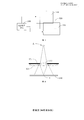
- FIG. 1 is a schematic diagram of optical path propagation at a boundary of an analysis lens of a prior art 3D display
- FIG. 2 is a schematic diagram of optical path propagation of a sample point of different angles of a prior art 3D display
- FIG. 3 is a schematic diagram showing the structure of a lens switching 3D display of the present invention.
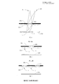
- FIG. 4 is a schematic diagram 1 of optical path propagation of a lens-switched 3D display of the present invention
- FIG. 5 is a schematic diagram 2 of optical path propagation of a lens-switched 3D display of the present invention.
- FIG. 6 is a partial structural schematic view 1 of a 3D image display of a first preferred embodiment of the lens switching 3D display of the present invention
- FIG. 7 is a partial schematic structural view 2 of a 3D image display of a first preferred embodiment of the lens switching 3D display of the present invention
- FIG. 8 is a partial schematic structural view 1 of a 3D image display of a second preferred embodiment of the lens switching 3D display of the present invention.
- FIG. 9 is a partial schematic structural view 2 of a 3D image display of a second preferred embodiment of the lens switching 3D display of the present invention.
- FIG. 10 is a partial schematic structural view 3 of a 3D image display of a second preferred embodiment of the lens switching 3D display of the present invention.
- FIG 11 is a partial structural view 4 of a 3D image display of a second preferred embodiment of the lens switching 3D display of the present invention.
- FIG. 3 is a schematic diagram showing the structure of a lens switching 3D display according to the present invention.
- the lens switching 3D display includes a synchronization mapping system 300, and an LCD display layer (LCD1) 310 and a lens array panel 320 which are sequentially stacked.
- an LCD occlusion layer (LCD2) 330 wherein the synchronization mapping system 300 is connected to the LCD display layer 310 and the LCD occlusion layer 330, respectively, for synchronizing the LCD display layer 310 and the LCD occlusion layer 330 to the image.
- the LCD display layer 310 and the LCD occlusion layer 330 are synchronized to display the 3D image and the occlusion pattern, respectively.
- FIG. 4 is a schematic diagram of optical path propagation of the lens switching 3D display of the present invention
- FIG. The optical path propagation diagram 2 of the lens switching 3D display of the present invention is a schematic diagram of optical path propagation of the lens switching 3D display of the present invention.
- the lens array plate 320 is composed of an array of a plurality of lens units 321; the lens array plate 320 is composed of a liquid crystal lens unit or a solid lens unit, and the lens unit 321 may be a cylindrical lens or a fly-eye lens, and the arrangement may be in close contact arrangement or not.
- the shape of the single lens unit 321 is circular, square, rectangular or other polygonal shape. The shape, arrangement and the like of the lens unit 321 in the lens array plate 320 are not limited herein.
- the area of the single light transmissive area 332 on the LCD occlusion layer 330 is smaller than the area of the single lens unit 321 on the lens array board 320. As can be seen from FIG. 4, the light at the edge of the lens unit 321 cannot pass, ensuring The boundary of the lens unit 321 corresponding to the occlusion area 331 is blocked, thereby effectively eliminating crosstalk caused by boundary scattering and unsharpness.
- A represents the position of the human eye and a represents the position of the sampling point on the LCD display layer 310.
- the area of the single light-transmissive region 332 on the LCD occlusion layer 330 is smaller than the area of the single lens unit 321 on the lens array plate 320, which is equivalent to reducing the area of the light-transmitting region 332, that is, the lens unit 321 corresponding to the occlusion region 331 is reduced.
- the light transmission aperture as can be seen from FIG. 5, since the light transmission aperture of the lens unit 321 is reduced, the sampling area of the b sampling point on the LCD display layer 310 is significantly smaller, that is, the image at the position B where the eye is located. It will be clearer. The crosstalk introduced by the aberration due to the different sampling point sizes at different angles is effectively reduced.
- the LCD occlusion layer 330 can be disposed between the lens array board 320 and the LCD display layer 310, that is, the position where the LCD occlusion layer 330 and the lens array board 320 are disposed can be reversed.
- FIG. 6 is a partial structural diagram 1 of a 3D image display of a first preferred embodiment of the lens switching 3D display of the present invention
- FIG. 7 is a first preferred embodiment of the lens switching 3D display of the present invention.
- the partial structure diagram 2 of the 3D image display when the synchronization is transmitted to the first frame (frame1) 3D display image of the LCD display layer 310, the LCD occlusion layer 330 blocks the odd number lens unit 1, and the synchronization map system is When transmitting to the second frame (frame2) 3D display image of the LCD display layer 310, the LCD occlusion layer 330 blocks the even-numbered lens unit 2, thus alternately displaying the 3D images of the odd-numbered and even-numbered lens units 321, thereby generating a 3D effect. .
- the refresh rate of the LCD display layer 310 and the LCD occlusion layer 330 is at least 120 Hz to ensure that the splash screen phenomenon is not recognized by the human eye.
- FIG. 8 is a partial structural diagram 1 of a 3D image display of a second preferred embodiment of the lens switching 3D display of the present invention
- FIG. 9 is a 3D of a second preferred embodiment of the lens switching 3D display of the present invention
- FIG. 10 is a partial structural diagram 3 of a 3D image display of a second preferred embodiment of the lens switching 3D display of the present invention
- FIG. 11 is a 3D image display of a second preferred embodiment of the lens switching 3D display of the present invention.
- the partial structure diagram is four; in this embodiment, the lens array plate 320 adopts a rectangular array structure, and four lens units 321 are used as a group of display units.
- the LCD occlusion layer (indicated by the occlusion area 331 in the figure) blocks the odd-numbered rows of the lens unit 321
- the LCD occlusion layer blocks the lens unit 321 of the odd-numbered rows; the synchronization map system transmits the third to the LCD display layer.
- the LCD occlusion layer blocks the lens unit 321 of the even-numbered even-numbered columns; when the synchronization system is transmitted to the fourth frame (frame4) 3D display image of the LCD display layer, the LCD occlusion layer occlusion
- the lens unit 321 of the even-numbered odd-numbered columns alternately blocks the different lens units 321 to display the 3D image in one display unit, and the same is true in other display units, thereby realizing the 3D display effect of the entire display layer.
- the refresh rate of the LCD display layer and the LCD occlusion layer is at least 240 Hz to ensure that the splash screen phenomenon is not recognized by the human eye.
- the display unit is not limited to the form in the above embodiment, and in the case of increasing the refresh frequency of the display layer and the LCD occlusion layer, the arrangement form of the lens unit 321 and the number of the lens units 321 in the display unit can be changed. Within the understanding of those skilled in the art, no further details are provided herein.
- the lens-switched 3D display provided by the embodiment of the invention increases the area of the black occlusion pattern by appropriately blocking the boundary of the lens unit, eliminating crosstalk caused by boundary scattering and not sharpening, and further reducing the aperture of the lens unit. , thereby reducing crosstalk introduced by aberrations due to different sizes of sampling points at different angles.
Landscapes
- Physics & Mathematics (AREA)
- General Physics & Mathematics (AREA)
- Optics & Photonics (AREA)
- Nonlinear Science (AREA)
- Engineering & Computer Science (AREA)
- Multimedia (AREA)
- Signal Processing (AREA)
- Mathematical Physics (AREA)
- Chemical & Material Sciences (AREA)
- Crystallography & Structural Chemistry (AREA)
- Testing, Inspecting, Measuring Of Stereoscopic Televisions And Televisions (AREA)
Abstract
一种透镜切换3D显示器,包括同步给图系统(300)、以及依次层叠设置的LCD显示图层(310)、透镜阵列板(320)和LCD遮挡图层(330),同步给图系统(300)与LCD显示图层(310)和LCD遮挡图层(330)连接,用于使LCD显示图层(310)和LCD遮挡图层(330)同步分别显示3D图像和遮挡图形。该透镜切换3D显示器,通过将黑色遮挡图形面积适当增大,以遮挡透镜单元(321)的边界,消除由边界散射和不锐利引入的串扰,另外,还相当于缩小了透镜单元(321)的孔径,从而减少了由于不同角度采样点大小不同而导致的像差引入的串扰。
Description
【技术领域】
本发明涉及3D显示器的技术领域,具体是涉及一种透镜切换3D显示器。
【背景技术】
传统的透镜切换,黑色遮挡图形与透镜等大小,不能克服如下缺陷:(1)工艺上的不足,导致透镜边界处存在散射,由于透镜边界处不够锐利,导致眼睛看到不该看到的光,引入串扰;(2)现有技术中一般采用的是球面或者柱面透镜,存在像差,大角度的采样点大于小角度采样点,请一并参阅图1和图2,图1是现有技术3D显示器的分析透镜边界处散射的光路传播示意图,图2是现有技术3D显示器的分析不同角度采样点的光路传播示意图;图中A、B点表示眼睛所处的位置,从图1中可以看出,透镜边界处不够锐利,导致眼睛看到不该看到的光,致使眼睛看到的光因不聚焦二模糊,图中a表示显示装置100上的采样点位置。图2中由于大角度的采样点大于小角度采样点,因此当在同一平面位置上采样时,会产生像差,这就意味着在大角度的时候看到不该看到的光线,即串扰,影响3D效果,甚至无3D效果。图2中a、b表示显示装置100上不同的采样位置。
【发明内容】
本发明实施例提供一种透镜切换3D显示器,以解决现有技术中工由于艺上的不足,导致透镜边界处存在散射以及由于不同角度采样点的大小不同而产生像差的技术问题。
为解决上述问题,本发明实施例提供了一种透镜切换3D显示器,所述透镜切换3D显示器包括同步给图系统、以及依次层叠设置的LCD显示图层、透镜阵列板和LCD遮挡图层,所述同步给图系统与所述LCD显示图层和所述LCD遮挡图层连接,用于使所述LCD显示图层和所述LCD遮挡图层同步分别显示3D图像和遮挡图形。
根据本发明一优选实施例,所述LCD遮挡图层上间隔设置有遮挡区和透光区,所述透镜阵列板有多个透镜单元阵列组成;其中,所述单个透光区的面积小于所述透镜阵列板上的单个透镜单元的面积,保证所述遮挡区对应的透镜单元的边界被遮挡住,以消除由边界散射和不锐利引入的串扰,同时相当于缩小了透光区的面积,即缩小了所述遮挡区对应的透镜单元的透光孔径,减少由于像差引入的串扰。
根据本发明一优选实施例,所述LCD遮挡图层可设于所述透镜阵列板与所述LCD显示图层之间。
根据本发明一优选实施例,所述透镜阵列板由液晶透镜单元组成或者固态透镜单元组成。
根据本发明一优选实施例,所述透镜阵列板上的透镜单元为柱状透镜或者复眼透镜,所述透镜单元紧密接触排列。
根据本发明一优选实施例,所述单个透镜单元的形状为圆形、正方形、矩形或者其他多边形。
根据本发明一优选实施例,所述同步给图系统传输给所述LCD显示图层的第一帧3D显示图像时,所述LCD遮挡图层遮挡奇数号透镜单元,所述同步给图系统传输给所述LCD显示图层的第二帧3D显示图像时,所述LCD遮挡图层遮挡偶数号透镜单元,如此交替显示奇数号和偶数号透镜单元的3D图像。
根据本发明一优选实施例,所述同步给图系统传输给所述LCD显示图层的第一帧3D显示图像时,所述LCD遮挡图层遮挡奇数行奇数列的透镜单元,所述同步给图系统传输给所述LCD显示图层的第二帧3D显示图像时,所述LCD遮挡图层遮挡奇数行偶数列的透镜单元,所述同步给图系统传输给所述LCD显示图层的第三帧3D显示图像时,所述LCD遮挡图层遮挡偶数行偶数列的透镜单元,所述同步给图系统传输给所述LCD显示图层的第四帧3D显示图像时,所述LCD遮挡图层遮挡偶数行奇数列的透镜单元,如此交替显示出3D图像。
根据本发明一优选实施例,所述LCD显示图层和所述LCD遮挡图层的刷新频率至少为120HZ。
根据本发明一优选实施例,所述LCD显示图层和所述LCD遮挡图层的刷新频率至少为240HZ。
相对于现有技术,本发明提供的透镜切换3D显示器,通过将黑色遮挡图形面积适当增大,以遮挡透镜单元的边界,消除由边界散射和不锐利引入的串扰,另外,还相当于缩小了透镜单元的孔径,从而减少了由于不同角度采样点大小不同而导致的像差引入的串扰。
【附图说明】
为了更清楚地说明本发明实施例中的技术方案,下面将对实施例描述中所需要使用的附图作简单地介绍,显而易见地,下面描述中的附图仅仅是本发明的一些实施例,对于本领域普通技术人员来讲,在不付出创造性劳动的前提下,还可以根据这些附图获得其他的附图。
图1是现有技术3D显示器的分析透镜边界处散射的光路传播示意图;
图2是现有技术3D显示器的分析不同角度采样点的光路传播示意图;
图3是本发明透镜切换3D显示器的结构示意简图;
图4是本发明透镜切换3D显示器的光路传播示意图一;
图5是本发明透镜切换3D显示器的光路传播示意图二;
图6是本发明透镜切换3D显示器第一优选实施例的3D图像显示的局部结构示意图一;
图7是本发明透镜切换3D显示器第一优选实施例的3D图像显示的局部结构示意图二;
图8是本发明透镜切换3D显示器第二优选实施例的3D图像显示的局部结构示意图一;
图9是本发明透镜切换3D显示器第二优选实施例的3D图像显示的局部结构示意图二;
图10是本发明透镜切换3D显示器第二优选实施例的3D图像显示的局部结构示意图三;以及
图11是本发明透镜切换3D显示器第二优选实施例的3D图像显示的局部结构示意图四。
【具体实施方式】
下面结合附图和实施例,对本发明作进一步的详细描述。特别指出的是,以下实施例仅用于说明本发明,但不对本发明的范围进行限定。同样的,以下实施例仅为本发明的部分实施例而非全部实施例,本领域普通技术人员在没有作出创造性劳动前提下所获得的所有其它实施例,都属于本发明保护的范围。
请参阅图3,图3是本发明透镜切换3D显示器的结构示意简图,该透镜切换3D显示器包括同步给图系统300、以及依次层叠设置的LCD显示图层(LCD1)310、透镜阵列板320和LCD遮挡图层(LCD2)330,其中,同步给图系统300分别与LCD显示图层310和LCD遮挡图层330连接,用于对LCD显示图层310和LCD遮挡图层330同步给图,使LCD显示图层310和LCD遮挡图层330同步分别显示3D图像和遮挡图形。
具体而言,LCD遮挡图层330上间隔设置有遮挡区331和透光区332,请一并参阅图4和图5,图4是本发明透镜切换3D显示器的光路传播示意图一,图5是本发明透镜切换3D显示器的光路传播示意图二。
该透镜阵列板320有多个透镜单元321阵列组成;透镜阵列板320由液晶透镜单元组成或者固态透镜单元组成,透镜单元321可以为柱状透镜或者复眼透镜,其排列形式可以为紧密接触排列或者不规则排列,单个透镜单元321的形状为圆形、正方形、矩形或者其他多边形,此处对透镜阵列板320内透镜单元321的形状、排列形式等都不做限定。
其中,LCD遮挡图层330上的单个透光区332的面积小于透镜阵列板320上的单个透镜单元321的面积,从图4中可以看出,在透镜单元321边缘处的光无法通过,保证遮挡区331对应的透镜单元321的边界被遮挡住,进而有效消除了由边界散射和不锐利引入的串扰。其中,A表示人眼所处的位置,a表示LCD显示图层310上采样点的位置。
LCD遮挡图层330上的单个透光区332的面积小于透镜阵列板320上的单个透镜单元321的面积,相当于缩小了透光区332的面积,即缩小了遮挡区331对应的透镜单元321的透光孔径,从图5中可以看出,由于透镜单元321的透光孔径缩小,b采样点在LCD显示图层310上的采样区域明显变小,即眼睛所处的位置B处的图像会更加清晰。有效减少了由于不同角度采样点大小不同而产生像差引入的串扰。
优选地,LCD遮挡图层330可设于透镜阵列板320与LCD显示图层310之间,即LCD遮挡图层330与透镜阵列板320设置位置可以对调。
请一并参阅图4至图7,其中,图6是本发明透镜切换3D显示器第一优选实施例的3D图像显示的局部结构示意图一,图7是本发明透镜切换3D显示器第一优选实施例的3D图像显示的局部结构示意图二;该同步给图系统传输给LCD显示图层310的第一帧(frame1)3D显示图像时,LCD遮挡图层330遮挡奇数号透镜单元1,同步给图系统传输给LCD显示图层310的第二帧(frame2)3D显示图像时,LCD遮挡图层330遮挡偶数号透镜单元2,如此交替显示奇数号和偶数号透镜单元321的3D图像,进而产生3D效果。其中,在本实施例中LCD显示图层310和LCD遮挡图层330的刷新频率至少为120HZ,以保证人眼不会识别到闪屏现象。
请一并参阅图8至图11,图8是本发明透镜切换3D显示器第二优选实施例的3D图像显示的局部结构示意图一,图9是本发明透镜切换3D显示器第二优选实施例的3D图像显示的局部结构示意图二,图10是本发明透镜切换3D显示器第二优选实施例的3D图像显示的局部结构示意图三以及图11是本发明透镜切换3D显示器第二优选实施例的3D图像显示的局部结构示意图四;该实施例中透镜阵列板320采用矩形阵列的结构,并且以四个透镜单元321作为一组显示单位。
同步给图系统传输给LCD显示图层(图中未示)的第一帧(frame1)3D显示图像时,LCD遮挡图层(图中用遮挡区331表示)遮挡奇数行奇数列的透镜单元321;同步给图系统传输给LCD显示图层的第二帧(frame2)3D显示图像时,LCD遮挡图层遮挡奇数行偶数列的透镜单元321;同步给图系统传输给LCD显示图层的第三帧(frame3)3D显示图像时,LCD遮挡图层遮挡偶数行偶数列的透镜单元321;同步给图系统传输给LCD显示图层的第四帧(frame4)3D显示图像时,LCD遮挡图层遮挡偶数行奇数列的透镜单元321,如此交替遮挡不同的透镜单元321,以在一个显示单位内显示出3D图像,同理在其他显示单位内也是如此,从而实现整个显示图层的3D显示效果。其中,在本实施例中LCD显示图层和LCD遮挡图层的刷新频率至少为240HZ,以保证人眼不会识别到闪屏现象。
当然,显示单位并不限于上述实施例中的形式,在增加显示图层和LCD遮挡图层的刷新频率的情况下,可以改变透镜单元321的排列形式以及显示单位内透镜单元321的数量。在本领域技术人员的理解范围内,此处不再赘述。
本发明实施例提供的透镜切换3D显示器,通过将黑色遮挡图形面积适当增大,以遮挡透镜单元的边界,消除由边界散射和不锐利引入的串扰,另外,还相当于缩小了透镜单元的孔径,从而减少了由于不同角度采样点的大小不同而导致像差引入的串扰。
以上所述仅为本发明的部分实施例,并非因此限制本发明的保护范围,凡是利用本发明说明书及附图内容所作的等效装置或等效流程变换,或直接或间接运用在其他相关的技术领域,均同理包括在本发明的专利保护范围内。
Claims (19)
- 一种透镜切换3D显示器,其中,所述透镜切换3D显示器包括同步给图系统、以及依次层叠设置的LCD显示图层、透镜阵列板和LCD遮挡图层,所述同步给图系统与所述LCD显示图层和所述LCD遮挡图层连接,用于使所述LCD显示图层和所述LCD遮挡图层同步分别显示3D图像和遮挡图形, 所述LCD遮挡图层上间隔设置有遮挡区和透光区,所述透镜阵列板有多个透镜单元阵列组成;其中,所述单个透光区的面积小于所述透镜阵列板上的单个透镜单元的面积,保证所述遮挡区对应的透镜单元的边界被遮挡住,以消除由边界散射和不锐利引入的串扰,同时相当于缩小了透光区的面积,即缩小了所述遮挡区对应的透镜单元的透光孔径,减少由于像差引入的串扰,所述透镜阵列板由液晶透镜单元组成或者固态透镜单元组成,所述透镜阵列板上的透镜单元为柱状透镜或者复眼透镜,所述透镜单元紧密接触排列。
- 一种透镜切换3D显示器,其中,所述透镜切换3D显示器包括同步给图系统、以及依次层叠设置的LCD显示图层、透镜阵列板和LCD遮挡图层,所述同步给图系统与所述LCD显示图层和所述LCD遮挡图层连接,用于使所述LCD显示图层和所述LCD遮挡图层同步分别显示3D图像和遮挡图形。
- 根据权利要求2所述的透镜切换3D显示器,其中,所述LCD遮挡图层上间隔设置有遮挡区和透光区,所述透镜阵列板有多个透镜单元阵列组成;其中,所述单个透光区的面积小于所述透镜阵列板上的单个透镜单元的面积,保证所述遮挡区对应的透镜单元的边界被遮挡住,以消除由边界散射和不锐利引入的串扰,同时相当于缩小了透光区的面积,即缩小了所述遮挡区对应的透镜单元的透光孔径,减少由于像差引入的串扰。
- 根据权利要求2所述的透镜切换3D显示器,其中,所述LCD遮挡图层可设于所述透镜阵列板与所述LCD显示图层之间。
- 根据权利要求3所述的透镜切换3D显示器,其中,所述透镜阵列板由液晶透镜单元组成或者固态透镜单元组成。
- 根据权利要求3所述的透镜切换3D显示器,其中,所述透镜阵列板上的透镜单元为柱状透镜或者复眼透镜,所述透镜单元紧密接触排列。
- 根据权利要求6所述的透镜切换3D显示器,其中,所述单个透镜单元的形状为圆形、正方形、矩形或者其他多边形。
- 根据权利要求3所述的透镜切换3D显示器,其中,所述同步给图系统传输给所述LCD显示图层的第一帧3D显示图像时,所述LCD遮挡图层遮挡奇数号透镜单元,所述同步给图系统传输给所述LCD显示图层的第二帧3D显示图像时,所述LCD遮挡图层遮挡偶数号透镜单元,如此交替显示奇数号和偶数号透镜单元的3D图像。
- 根据权利要求8所述的透镜切换3D显示器,其中,所述LCD显示图层和所述LCD遮挡图层的刷新频率至少为120HZ。
- 根据权利要求4所述的透镜切换3D显示器,其中,所述同步给图系统传输给所述LCD显示图层的第一帧3D显示图像时,所述LCD遮挡图层遮挡奇数号透镜单元,所述同步给图系统传输给所述LCD显示图层的第二帧3D显示图像时,所述LCD遮挡图层遮挡偶数号透镜单元,如此交替显示奇数号和偶数号透镜单元的3D图像。
- 根据权利要求10所述的透镜切换3D显示器,其中,所述LCD显示图层和所述LCD遮挡图层的刷新频率至少为120HZ。
- 根据权利要求5所述的透镜切换3D显示器,其中,所述同步给图系统传输给所述LCD显示图层的第一帧3D显示图像时,所述LCD遮挡图层遮挡奇数号透镜单元,所述同步给图系统传输给所述LCD显示图层的第二帧3D显示图像时,所述LCD遮挡图层遮挡偶数号透镜单元,如此交替显示奇数号和偶数号透镜单元的3D图像。
- 根据权利要求12所述的透镜切换3D显示器,其中,所述LCD显示图层和所述LCD遮挡图层的刷新频率至少为120HZ。
- 根据权利要求6所述的透镜切换3D显示器,其中,所述同步给图系统传输给所述LCD显示图层的第一帧3D显示图像时,所述LCD遮挡图层遮挡奇数号透镜单元,所述同步给图系统传输给所述LCD显示图层的第二帧3D显示图像时,所述LCD遮挡图层遮挡偶数号透镜单元,如此交替显示奇数号和偶数号透镜单元的3D图像。
- 根据权利要求14所述的透镜切换3D显示器,其中,所述LCD显示图层和所述LCD遮挡图层的刷新频率至少为120HZ。
- 根据权利要求3所述的透镜切换3D显示器,其中,所述同步给图系统传输给所述LCD显示图层的第一帧3D显示图像时,所述LCD遮挡图层遮挡奇数行奇数列的透镜单元,所述同步给图系统传输给所述LCD显示图层的第二帧3D显示图像时,所述LCD遮挡图层遮挡奇数行偶数列的透镜单元,所述同步给图系统传输给所述LCD显示图层的第三帧3D显示图像时,所述LCD遮挡图层遮挡偶数行偶数列的透镜单元,所述同步给图系统传输给所述LCD显示图层的第四帧3D显示图像时,所述LCD遮挡图层遮挡偶数行奇数列的透镜单元,如此交替显示出3D图像。
- 根据权利要求16所述的透镜切换3D显示器,其中,所述LCD显示图层和所述LCD遮挡图层的刷新频率至少为240HZ。
- 根据权利要求6所述的透镜切换3D显示器,其中,所述同步给图系统传输给所述LCD显示图层的第一帧3D显示图像时,所述LCD遮挡图层遮挡奇数行奇数列的透镜单元,所述同步给图系统传输给所述LCD显示图层的第二帧3D显示图像时,所述LCD遮挡图层遮挡奇数行偶数列的透镜单元,所述同步给图系统传输给所述LCD显示图层的第三帧3D显示图像时,所述LCD遮挡图层遮挡偶数行偶数列的透镜单元,所述同步给图系统传输给所述LCD显示图层的第四帧3D显示图像时,所述LCD遮挡图层遮挡偶数行奇数列的透镜单元,如此交替显示出3D图像。
- 根据权利要求18所述的透镜切换3D显示器,其中,所述LCD显示图层和所述LCD遮挡图层的刷新频率至少为240HZ。
Priority Applications (1)
| Application Number | Priority Date | Filing Date | Title |
|---|---|---|---|
| US14/433,670 US9817239B2 (en) | 2014-12-30 | 2015-01-06 | Three-dimensional display device having lens-switching function |
Applications Claiming Priority (2)
| Application Number | Priority Date | Filing Date | Title |
|---|---|---|---|
| CN201410850917.0A CN104503096A (zh) | 2014-12-30 | 2014-12-30 | 一种透镜切换3d显示器 |
| CN201410850917.0 | 2014-12-30 |
Publications (1)
| Publication Number | Publication Date |
|---|---|
| WO2016106792A1 true WO2016106792A1 (zh) | 2016-07-07 |
Family
ID=52944504
Family Applications (1)
| Application Number | Title | Priority Date | Filing Date |
|---|---|---|---|
| PCT/CN2015/070190 Ceased WO2016106792A1 (zh) | 2014-12-30 | 2015-01-06 | 一种透镜切换3d显示器 |
Country Status (3)
| Country | Link |
|---|---|
| US (1) | US9817239B2 (zh) |
| CN (1) | CN104503096A (zh) |
| WO (1) | WO2016106792A1 (zh) |
Cited By (1)
| Publication number | Priority date | Publication date | Assignee | Title |
|---|---|---|---|---|
| CN114660824A (zh) * | 2022-04-18 | 2022-06-24 | 北京邮电大学 | 一种裸眼3d显示光学器件 |
Families Citing this family (6)
| Publication number | Priority date | Publication date | Assignee | Title |
|---|---|---|---|---|
| KR102629389B1 (ko) * | 2016-03-25 | 2024-01-25 | 삼성디스플레이 주식회사 | 액정 렌즈 및 이를 포함하는 표시 장치 |
| KR102671795B1 (ko) * | 2016-09-27 | 2024-06-03 | 삼성전자주식회사 | 증강 현실 영상을 제공하는 방법, 디바이스 및 기록매체 |
| CN111445786B (zh) * | 2019-01-16 | 2022-06-03 | 北京小米移动软件有限公司 | 电子设备及屏幕模组 |
| CN110244469B (zh) * | 2019-06-19 | 2021-03-23 | 中国人民解放军陆军装甲兵学院 | 一种定向散射器位置和扩散角度的确定方法及系统 |
| CN111258084A (zh) * | 2020-01-19 | 2020-06-09 | 吉林大学 | 一种led全视差集成成像显示方法 |
| CN115524861B (zh) * | 2021-06-25 | 2025-09-12 | 京东方科技集团股份有限公司 | 裸眼3d显示模组、其驱动方法及裸眼3d显示装置 |
Citations (4)
| Publication number | Priority date | Publication date | Assignee | Title |
|---|---|---|---|---|
| CN1573421A (zh) * | 2003-06-17 | 2005-02-02 | 有限会社海电话 | 显示装置 |
| CN101507288A (zh) * | 2006-08-17 | 2009-08-12 | 皇家飞利浦电子股份有限公司 | 显示设备 |
| CN102253494A (zh) * | 2010-05-19 | 2011-11-23 | 介面光电股份有限公司 | 立体影像成像装置的改良结构 |
| CN103562777A (zh) * | 2011-05-30 | 2014-02-05 | 皇家飞利浦有限公司 | 自动立体显示设备 |
Family Cites Families (8)
| Publication number | Priority date | Publication date | Assignee | Title |
|---|---|---|---|---|
| CN100512453C (zh) * | 2001-08-21 | 2009-07-08 | 皇家飞利浦电子股份有限公司 | 具有观察者跟踪的自动立体显示器 |
| JP4934974B2 (ja) * | 2005-03-17 | 2012-05-23 | エプソンイメージングデバイス株式会社 | 画像表示装置 |
| JP4331134B2 (ja) * | 2005-03-25 | 2009-09-16 | 株式会社東芝 | 立体画像表示装置 |
| KR101439842B1 (ko) * | 2007-06-25 | 2014-09-12 | 삼성전자주식회사 | 백라이트 유닛 및 이를 채용한 2d/3d 겸용영상표시장치 |
| US8659830B2 (en) * | 2009-12-21 | 2014-02-25 | 3M Innovative Properties Company | Optical films enabling autostereoscopy |
| KR20120087647A (ko) * | 2011-01-28 | 2012-08-07 | 삼성전자주식회사 | 표시 장치 |
| US20130100120A1 (en) * | 2011-10-25 | 2013-04-25 | Chimei Innolux Corporation | 3d image display devices |
| JP2014060380A (ja) * | 2012-06-14 | 2014-04-03 | Rohm Co Ltd | 光電変換装置 |
-
2014
- 2014-12-30 CN CN201410850917.0A patent/CN104503096A/zh active Pending
-
2015
- 2015-01-06 US US14/433,670 patent/US9817239B2/en active Active
- 2015-01-06 WO PCT/CN2015/070190 patent/WO2016106792A1/zh not_active Ceased
Patent Citations (4)
| Publication number | Priority date | Publication date | Assignee | Title |
|---|---|---|---|---|
| CN1573421A (zh) * | 2003-06-17 | 2005-02-02 | 有限会社海电话 | 显示装置 |
| CN101507288A (zh) * | 2006-08-17 | 2009-08-12 | 皇家飞利浦电子股份有限公司 | 显示设备 |
| CN102253494A (zh) * | 2010-05-19 | 2011-11-23 | 介面光电股份有限公司 | 立体影像成像装置的改良结构 |
| CN103562777A (zh) * | 2011-05-30 | 2014-02-05 | 皇家飞利浦有限公司 | 自动立体显示设备 |
Cited By (1)
| Publication number | Priority date | Publication date | Assignee | Title |
|---|---|---|---|---|
| CN114660824A (zh) * | 2022-04-18 | 2022-06-24 | 北京邮电大学 | 一种裸眼3d显示光学器件 |
Also Published As
| Publication number | Publication date |
|---|---|
| US20160341971A1 (en) | 2016-11-24 |
| CN104503096A (zh) | 2015-04-08 |
| US9817239B2 (en) | 2017-11-14 |
Similar Documents
| Publication | Publication Date | Title |
|---|---|---|
| WO2016106792A1 (zh) | 一种透镜切换3d显示器 | |
| CN102628999B (zh) | 一种3d显示方法及显示装置 | |
| JPH1032843A (ja) | 3次元画像表示用の液晶表示装置 | |
| CN108594448B (zh) | 高光学效率和均匀分辨率双视3d显示装置及方法 | |
| WO2017128722A1 (zh) | 三维显示装置 | |
| WO2014127583A1 (zh) | 3d显示控制方法及3d显示控制装置 | |
| WO2014043924A1 (zh) | 一种阵列基板及液晶显示面板 | |
| US20140152925A1 (en) | Liquid crystal lens module and 3d display device | |
| US20150156482A1 (en) | Three-dimensional (3d) liquid crystal display (lcd) device, 3d lcd display system and 3d image display driving method | |
| WO2015078032A1 (zh) | 显示装置及液晶盒透镜面板 | |
| CN105303979A (zh) | 多画面显示面板、显示系统及驱动方法 | |
| WO2013123801A1 (zh) | 裸眼3d显示方法和裸眼3d显示装置 | |
| CN102872589A (zh) | 影像显示的控制方法以及显示系统 | |
| CN106094386B (zh) | 液晶透镜、显示装置和曲面显示方法 | |
| CN102722045B (zh) | 立体显示器 | |
| US20160255337A1 (en) | Three-dimensional image display apparatus and three-dimensional image display | |
| WO2011143901A1 (zh) | 平面/立体可切换型液晶显示装置 | |
| WO2016070451A1 (zh) | 一种3d液晶显示器及其制作方法 | |
| CN209946543U (zh) | 高分辨率双视3d显示装置 | |
| CN209707824U (zh) | 高分辨率集成成像双视3d显示装置 | |
| CN208459701U (zh) | 同视区的无串扰和均匀分辨率双视3d显示装置 | |
| CN102510507A (zh) | 一种三维图像显示装置 | |
| Osada et al. | Design of ghost-free aerial display by using polarizing plate and dihedral corner reflector array | |
| CN203587894U (zh) | 大视角定向成像透镜阵列结构 | |
| WO2013085222A1 (ko) | 3차원 영상 표시 장치 및 방법 |
Legal Events
| Date | Code | Title | Description |
|---|---|---|---|
| WWE | Wipo information: entry into national phase |
Ref document number: 14433670 Country of ref document: US |
|
| 121 | Ep: the epo has been informed by wipo that ep was designated in this application |
Ref document number: 15874485 Country of ref document: EP Kind code of ref document: A1 |
|
| NENP | Non-entry into the national phase |
Ref country code: DE |
|
| 122 | Ep: pct application non-entry in european phase |
Ref document number: 15874485 Country of ref document: EP Kind code of ref document: A1 |