WO2016104802A1 - Système de purification de gaz d'échappement et procédé de commande de système de purification de gaz d'échappement - Google Patents
Système de purification de gaz d'échappement et procédé de commande de système de purification de gaz d'échappement Download PDFInfo
- Publication number
- WO2016104802A1 WO2016104802A1 PCT/JP2015/086438 JP2015086438W WO2016104802A1 WO 2016104802 A1 WO2016104802 A1 WO 2016104802A1 JP 2015086438 W JP2015086438 W JP 2015086438W WO 2016104802 A1 WO2016104802 A1 WO 2016104802A1
- Authority
- WO
- WIPO (PCT)
- Prior art keywords
- exhaust
- injector
- learning
- value
- injection amount
- Prior art date
Links
Images


Classifications
-
- F—MECHANICAL ENGINEERING; LIGHTING; HEATING; WEAPONS; BLASTING
- F01—MACHINES OR ENGINES IN GENERAL; ENGINE PLANTS IN GENERAL; STEAM ENGINES
- F01N—GAS-FLOW SILENCERS OR EXHAUST APPARATUS FOR MACHINES OR ENGINES IN GENERAL; GAS-FLOW SILENCERS OR EXHAUST APPARATUS FOR INTERNAL COMBUSTION ENGINES
- F01N3/00—Exhaust or silencing apparatus having means for purifying, rendering innocuous, or otherwise treating exhaust
- F01N3/02—Exhaust or silencing apparatus having means for purifying, rendering innocuous, or otherwise treating exhaust for cooling, or for removing solid constituents of, exhaust
- F01N3/021—Exhaust or silencing apparatus having means for purifying, rendering innocuous, or otherwise treating exhaust for cooling, or for removing solid constituents of, exhaust by means of filters
- F01N3/023—Exhaust or silencing apparatus having means for purifying, rendering innocuous, or otherwise treating exhaust for cooling, or for removing solid constituents of, exhaust by means of filters using means for regenerating the filters, e.g. by burning trapped particles
- F01N3/025—Exhaust or silencing apparatus having means for purifying, rendering innocuous, or otherwise treating exhaust for cooling, or for removing solid constituents of, exhaust by means of filters using means for regenerating the filters, e.g. by burning trapped particles using fuel burner or by adding fuel to exhaust
-
- F—MECHANICAL ENGINEERING; LIGHTING; HEATING; WEAPONS; BLASTING
- F01—MACHINES OR ENGINES IN GENERAL; ENGINE PLANTS IN GENERAL; STEAM ENGINES
- F01N—GAS-FLOW SILENCERS OR EXHAUST APPARATUS FOR MACHINES OR ENGINES IN GENERAL; GAS-FLOW SILENCERS OR EXHAUST APPARATUS FOR INTERNAL COMBUSTION ENGINES
- F01N3/00—Exhaust or silencing apparatus having means for purifying, rendering innocuous, or otherwise treating exhaust
- F01N3/08—Exhaust or silencing apparatus having means for purifying, rendering innocuous, or otherwise treating exhaust for rendering innocuous
- F01N3/10—Exhaust or silencing apparatus having means for purifying, rendering innocuous, or otherwise treating exhaust for rendering innocuous by thermal or catalytic conversion of noxious components of exhaust
- F01N3/24—Exhaust or silencing apparatus having means for purifying, rendering innocuous, or otherwise treating exhaust for rendering innocuous by thermal or catalytic conversion of noxious components of exhaust characterised by constructional aspects of converting apparatus
- F01N3/28—Construction of catalytic reactors
-
- F—MECHANICAL ENGINEERING; LIGHTING; HEATING; WEAPONS; BLASTING
- F01—MACHINES OR ENGINES IN GENERAL; ENGINE PLANTS IN GENERAL; STEAM ENGINES
- F01N—GAS-FLOW SILENCERS OR EXHAUST APPARATUS FOR MACHINES OR ENGINES IN GENERAL; GAS-FLOW SILENCERS OR EXHAUST APPARATUS FOR INTERNAL COMBUSTION ENGINES
- F01N3/00—Exhaust or silencing apparatus having means for purifying, rendering innocuous, or otherwise treating exhaust
- F01N3/08—Exhaust or silencing apparatus having means for purifying, rendering innocuous, or otherwise treating exhaust for rendering innocuous
- F01N3/10—Exhaust or silencing apparatus having means for purifying, rendering innocuous, or otherwise treating exhaust for rendering innocuous by thermal or catalytic conversion of noxious components of exhaust
- F01N3/24—Exhaust or silencing apparatus having means for purifying, rendering innocuous, or otherwise treating exhaust for rendering innocuous by thermal or catalytic conversion of noxious components of exhaust characterised by constructional aspects of converting apparatus
- F01N3/36—Arrangements for supply of additional fuel
-
- F—MECHANICAL ENGINEERING; LIGHTING; HEATING; WEAPONS; BLASTING
- F02—COMBUSTION ENGINES; HOT-GAS OR COMBUSTION-PRODUCT ENGINE PLANTS
- F02D—CONTROLLING COMBUSTION ENGINES
- F02D41/00—Electrical control of supply of combustible mixture or its constituents
- F02D41/02—Circuit arrangements for generating control signals
- F02D41/14—Introducing closed-loop corrections
Definitions
- the present invention relates to an exhaust purification system and an exhaust purification system control method.
- a NOx occlusion reduction type catalyst is known as a catalyst for reducing and purifying nitrogen compounds (NOx) in exhaust gas discharged from an internal combustion engine.
- the NOx occlusion reduction catalyst occludes NOx contained in the exhaust when the exhaust is in a lean atmosphere, and harmless NOx occluded by hydrocarbons contained in the exhaust when the exhaust is in a rich atmosphere. And release. For this reason, when the NOx occlusion amount of the catalyst reaches a predetermined amount, so-called NOx purge that makes the exhaust gas rich by exhaust pipe injection needs to be performed periodically in order to recover the NOx occlusion capacity (for example, patents) Reference 1).
- the NOx occlusion reduction type catalyst also occludes sulfur oxide (hereinafter referred to as SOx) contained in the exhaust gas.
- SOx sulfur oxide
- the SOx occlusion amount increases, there is a problem that the NOx purification ability of the NOx occlusion reduction type catalyst is lowered. For this reason, when the SOx occlusion amount reaches a predetermined amount, unburnt fuel is supplied to the upstream oxidation catalyst by exhaust pipe injection in order to remove SOx from the NOx occlusion reduction catalyst and recover from S poisoning. Therefore, it is necessary to periodically perform a so-called SOx purge for raising the exhaust temperature to the SOx separation temperature (see, for example, Patent Document 2).
- the exhaust injector may cause an error between the commanded injection amount and the actual injection amount due to the influence of deterioration over time, characteristic changes, individual differences, etc., to improve the injection accuracy, eliminate the influence of this error. There is a need.
- An object of the exhaust purification system and the exhaust purification system control method of the present disclosure is to effectively reduce an error between the instructed injection amount of the exhaust injector and the actual injection amount.
- An exhaust purification system of the present disclosure includes an exhaust aftertreatment device including a catalyst that is provided in an exhaust passage of an internal combustion engine and purifies exhaust gas, and an exhaust passage that is provided upstream of the exhaust aftertreatment device and is provided in the exhaust passage.
- An exhaust injector that injects fuel; an exhaust measurement means that is provided in an exhaust passage downstream of the exhaust injector to acquire an actual measurement value of exhaust; and the internal combustion engine is in a period during which the exhaust injector performs fuel injection.
- First learning means for learning a correction amount of the command injection amount to be output to the exhaust injector based on a difference between an estimated value of exhaust gas estimated from an engine operating state and an actual measurement value acquired by the exhaust gas measurement means.
- first correction means for correcting the command injection amount output to the exhaust injector based on the correction amount learned by the first learning means.
- An exhaust purification system of the present disclosure is provided in an exhaust passage of an internal combustion engine, and has an exhaust aftertreatment device having a catalyst for purifying exhaust gas, and is provided at a position upstream of the exhaust aftertreatment device in the exhaust passage.
- An injector that injects fuel into the exhaust passage, a sensor that is provided at a position downstream of the injector in the exhaust passage, detects a component or state of the exhaust, and outputs a measured value;
- An exhaust purification system comprising a control unit that controls at least one of an intake air flow rate and a fuel injection amount of an internal combustion engine, wherein the control unit operates to perform the following processing: A fuel injection process for outputting a signal indicating an instruction injection amount to the injector and controlling the injector to inject fuel into the exhaust passage; A calculation process for estimating a component or a state of the exhaust gas based on an operating state of the internal combustion engine and calculating an estimated value; A learning process for learning a correction amount to be applied to the command injection amount based on the actual measurement value output from the
- An exhaust purification system control method includes an internal combustion engine, an exhaust aftertreatment device disposed in an exhaust passage of the internal combustion engine and having a catalyst for purifying exhaust gas, and an exhaust aftertreatment device in the exhaust passage.
- An exhaust purification system control method comprising an injector provided at an upstream position and injecting fuel into the exhaust passage, wherein an injection amount is instructed to the injector, A fuel injection process for controlling the injector to inject fuel; a measurement process for measuring a component or state of the exhaust gas at a position downstream of the injector in the exhaust passage as a measured value; based on an operating state of the internal combustion engine Estimation process for estimating the exhaust gas component or state as an estimated value; during execution of the fuel injection process, the measured value and the estimated value Based on the learning process for learning a correction amount to be applied to the instructed injection amount; including the correction process, the application of the correction amount learned by and the learning process to the instructed injection amount.
- the exhaust purification system and the exhaust purification system control method of the present disclosure it is possible to effectively reduce an error between the instructed injection amount of the exhaust injector and the actual injection amount.
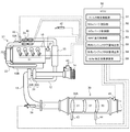
- FIG. 1 is an overall configuration diagram showing an exhaust purification system according to the present embodiment.
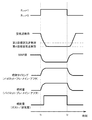
- FIG. 2 is a timing chart for explaining the SOx purge control according to the present embodiment.
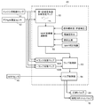
- FIG. 3 is a block diagram showing the MAF target value setting process during SOx purge lean control according to the present embodiment.
- FIG. 4 is a block diagram showing a target injection amount setting process during SOx purge rich control according to the present embodiment.
- FIG. 5 is a timing chart illustrating the catalyst temperature adjustment control of the SOx purge control according to the present embodiment.
- FIG. 6 is a timing chart for explaining the NOx purge control according to the present embodiment.
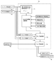
- FIG. 7 is a block diagram showing the MAF target value setting process during NOx purge lean control according to this embodiment.
- FIG. 8 is a block diagram showing a target injection amount setting process during NOx purge rich control according to the present embodiment.
- FIG. 9 is a block diagram showing processing for correcting the injection amount of the in-cylinder injector according to the present embodiment.
- FIG. 10 is a flowchart for explaining the calculation processing of the learning correction coefficient of the in-cylinder injector according to the present embodiment.
- FIG. 11 is a block diagram showing the process of correcting the injection amount learning of the exhaust injector according to the present embodiment.
- FIG. 12 is a block diagram showing MAF correction coefficient setting processing according to this embodiment.
- each cylinder of a diesel engine (hereinafter simply referred to as an engine) 10 is provided with an in-cylinder injector 11 that directly injects high-pressure fuel accumulated in a common rail (not shown) into each cylinder.
- the fuel injection amount and fuel injection timing of each in-cylinder injector 11 are controlled according to an instruction signal input from an electronic control unit (hereinafter referred to as ECU) 50.
- ECU electronice control unit
- An intake passage 12 for introducing fresh air is connected to the intake manifold 10A of the engine 10, and an exhaust passage 13 for connecting exhaust to the outside is connected to the exhaust manifold 10B.
- an air cleaner 14 an intake air amount sensor (hereinafter referred to as MAF (Mass Air Flow) sensor) 40, a compressor 20A of the variable displacement supercharger 20, an intercooler 15, an intake throttle valve are arranged in order from the intake upstream side. 16 etc. are provided.
- the exhaust passage 13 is provided with a turbine 20B of the variable displacement supercharger 20, an exhaust aftertreatment device 30 and the like in order from the exhaust upstream side.
- the engine 10 is provided with an engine speed sensor 41, an accelerator opening sensor 42, and a boost pressure sensor 46.
- the MAF sensor 40 that measures and detects the mass flow rate is used as a sensor that measures and detects the intake air amount of the engine (intake flow rate (Suction Air Flow)).
- intake flow rate Sudden Air Flow
- a different type of flow rate (AirFFlow) sensor from the MAF sensor 40 or a means in place of the flow rate sensor may be used.
- the EGR device 21 includes an EGR passage 22 that connects the exhaust manifold 10B and the intake manifold 10A, an EGR cooler 23 that cools the EGR gas, and an EGR valve 24 that adjusts the EGR amount.
- the exhaust aftertreatment device 30 is configured by arranging an oxidation catalyst 31, a NOx occlusion reduction type catalyst 32, and a particulate filter (hereinafter simply referred to as a filter) 33 in order from the exhaust upstream side in a case 30A.
- An exhaust injector 34 that injects unburned fuel (mainly hydrocarbon (HC)) into the exhaust passage 13 in the exhaust passage 13 upstream of the oxidation catalyst 31 in response to an instruction signal input from the ECU 50. Is provided.
- unburned fuel mainly hydrocarbon (HC)
- exhaust injector 34 is also referred to as an exhaust pipe injector or simply an injector.
- the oxidation catalyst 31 is formed, for example, by carrying an oxidation catalyst component on the surface of a ceramic carrier such as a honeycomb structure.
- a ceramic carrier such as a honeycomb structure.
- the NOx occlusion reduction type catalyst 32 is formed, for example, by supporting an alkali metal or the like on the surface of a ceramic carrier such as a honeycomb structure.
- the NOx occlusion reduction type catalyst 32 occludes NOx in the exhaust when the exhaust air-fuel ratio is in a lean state, and occludes with a reducing agent (HC or the like) contained in the exhaust when the exhaust air-fuel ratio is in a rich state. NOx is reduced and purified.
- the filter 33 is formed, for example, by arranging a large number of cells partitioned by porous partition walls along the flow direction of the exhaust gas and alternately plugging the upstream side and the downstream side of these cells. .
- the filter 33 collects particulate matter (PM) in the exhaust gas in the pores and surfaces of the partition walls, and when the estimated amount of PM deposition reaches a predetermined amount, so-called filter forced regeneration is performed to remove it.
- Filter forced regeneration is performed by supplying unburned fuel to the upstream side oxidation catalyst 31 by exhaust pipe injection or post injection, and raising the exhaust temperature flowing into the filter 33 to the PM combustion temperature.
- the first exhaust temperature sensor 43 is provided on the upstream side of the oxidation catalyst 31 and detects the exhaust temperature flowing into the oxidation catalyst 31.
- the second exhaust temperature sensor 44 is provided between the oxidation catalyst 31 and the NOx storage reduction catalyst 32 and detects the exhaust temperature flowing into the NOx storage reduction catalyst 32.
- the NOx / lambda sensor 45 is an example of the exhaust gas measurement means of the present invention, and is provided on the downstream side of the filter 33, and the NOx value and lambda value (hereinafter, referred to as exhaust gas) of the exhaust gas that has passed through the NOx storage reduction catalyst 32. Detect excess air ratio).
- the ECU 50 performs various controls of the engine 10 and the like, and includes a known CPU, ROM, RAM, input port, output port, and the like. In order to perform these various controls, the sensor values of the sensors 40 to 46 are input to the ECU 50.
- the ECU 50 also includes a filter regeneration control unit 51, a SOx purge control unit 60, a NOx purge control unit 70, a MAF follow-up control unit 80, an in-cylinder injector learning correction unit 90, an exhaust injector learning correction unit 94, and a MAF.
- the correction coefficient calculation unit 98 is included as a part of functional elements. Each of these functional elements will be described as being included in the ECU 50 which is an integral hardware, but any one of these may be provided in separate hardware.
- the filter regeneration control unit 51 estimates the PM accumulation amount of the filter 33 from the travel distance of the vehicle or the differential pressure across the filter detected by a differential pressure sensor (not shown), and the estimated PM accumulation amount exceeds a predetermined upper limit threshold. And the forced regeneration flag F DPF is turned on (see time t 1 in FIG. 2). When the forced regeneration flag F DPF is turned on, an instruction signal for executing exhaust pipe injection (exhaust pipe injection system) is transmitted to the exhaust injector 34, or post injection (post injection system) to each in-cylinder injector 11. ) Is transmitted to raise the exhaust gas temperature to the PM combustion temperature (for example, about 550 ° C.).
- the forced regeneration flag F DPF is, PM deposition estimation amount is turned off drops to a predetermined lower limit threshold indicating the burn off (determination threshold value) (see time t 2 in FIG. 2).
- the SOx purge control unit 60 makes the exhaust rich and raises the exhaust temperature to a sulfur desorption temperature (for example, about 600 ° C.) to recover the NOx occlusion reduction type catalyst 32 from SOx poisoning (hereinafter, this control). (Referred to as SOx purge control).
- FIG. 2 shows a timing chart of the SOx purge control of this embodiment.
- SOx purge flag F SP to start SOx purge control is turned off and on at the same time forced regeneration flag F DPF (see time t 2 in FIG. 2).
- F DPF forced regeneration flag
- the enrichment by the SOx purge control is performed by adjusting the excess air ratio to the lean side from the theoretical air-fuel ratio equivalent value (about 1.0) from the steady operation (for example, about 1.5) by the air system control.
- SOx purge lean control for reducing to 1 target excess air ratio (for example, about 1.3) and injection system control to reduce the excess air ratio from the first target excess air ratio to the second target excess air ratio on the rich side (for example, about 0) This is realized by using together with the SOx purge rich control that lowers to .9). Details of the SOx purge lean control and the SOx purge rich control will be described below.
- FIG. 3 is a block diagram illustrating a process for setting the MAF target value MAF SPL_Trgt during the SOx purge lean control.
- the first target excess air ratio setting map 61 is a map that is referred to based on the engine speed Ne and the accelerator opening Q (the fuel injection amount of the engine 10), and the engine speed Ne, the accelerator opening Q,
- the excess air ratio target value ⁇ SPL_Trgt (first target excess air ratio) at the time of SOx purge lean control corresponding to is preset based on experiments or the like.
- the excess air ratio target value ⁇ SPL_Trgt at the time of SOx purge lean control is read from the first target excess air ratio setting map 61 using the engine speed Ne and the accelerator opening Q as input signals, and is sent to the MAF target value calculation unit 62. Entered. Further, the MAF target value calculation unit 62 calculates the MAF target value MAF SPL_Trgt during the SOx purge lean control based on the following formula (1).
- Equation (1) Q fnl_cord represents a learning-corrected fuel injection amount (excluding post-injection) described later, Ro Fuel represents fuel specific gravity, AFR sto represents a theoretical air-fuel ratio, and Maf_corr represents a MAF correction coefficient described later. Yes.
- MAF target value MAF SPL_Trgt calculated by the MAF target value calculation unit 62, when the SOx purge flag F SP is turned on (see time t 2 in FIG. 2) is input to the lamp unit 63.
- the ramp processing unit 63 reads the ramp coefficient from the + ramp coefficient map 63A and the ⁇ ramp coefficient map 63B using the engine speed Ne and the accelerator opening Q as input signals, and obtains the MAF target ramp value MAF SPL_Trgt_Ramp to which the ramp coefficient is added. Input to the valve control unit 64.
- the valve control unit 64 throttles the intake throttle valve 16 to the close side and opens the EGR valve 24 to the open side so that the actual MAF value MAF Act input from the MAF sensor 40 becomes the MAF target ramp value MAF SPL_Trgt_Ramp. Execute control.
- the MAF target value MAF SPL_Trgt is set based on the excess air ratio target value ⁇ SPL_Trgt read from the first target excess air ratio setting map 61 and the fuel injection amount of each in-cylinder injector 11.
- the air system operation is feedback-controlled based on the MAF target value MAF SPL_Trgt .
- the MAF target value MAF SPL_Trgt can be set by feedforward control. It is possible to effectively eliminate influences such as deterioration, characteristic changes, and individual differences.
- FIG. 4 is a block diagram showing processing for setting the target injection amount Q SPR_Trgt (injection amount per unit time) of exhaust pipe injection or post injection in SOx purge rich control.
- the second target excess air ratio setting map 65 is a map that is referred to based on the engine speed Ne and the accelerator opening Q, and at the time of SOx purge rich control corresponding to the engine speed Ne and the accelerator opening Q.
- the excess air ratio target value ⁇ SPR_Trgt (second target excess air ratio) is set in advance based on experiments or the like.
- the excess air ratio target value ⁇ SPR_Trgt at the time of SOx purge rich control is read from the second target excess air ratio setting map 65 using the engine speed Ne and the accelerator opening Q as input signals, and an injection quantity target value calculation unit 66. Further, the injection amount target value calculation unit 66 calculates the target injection amount Q SPR_Trgt during the SOx purge rich control based on the following formula (2).
- MAF SPL_Trgt is the MAF target value at the SOx purge lean, and is input from the above-described MAF target value calculation unit 62.
- Q fnlRaw_cord is a fuel injection amount (excluding post-injection) after application of learning corrected MAF follow-up control, which will be described later,
- Ro Fuel is fuel specific gravity
- AFR sto is a theoretical air fuel ratio
- Maf_corr is a MAF correction coefficient described later. Show.
- the target injection amount Q SPR_Trgt calculated by the injection amount target value calculation unit 66 is transmitted as an injection instruction signal to the exhaust injector 34 or each in-cylinder injector 11 when a SOx purge rich flag F SPR described later is turned on.
- the target injection amount Q SPR_Trgt is set based on the air excess rate target value ⁇ SPR_Trgt read from the second target air excess rate setting map 65 and the fuel injection amount of each in-cylinder injector 11. It is supposed to be.
- the sensor value of the lambda sensor is not used. The exhaust can be effectively reduced to a desired excess air ratio required for SOx purge rich control.
- the target injection amount Q SPR_Trgt can be set by feedforward control. Effects such as deterioration and characteristic changes can be effectively eliminated.
- the exhaust temperature (hereinafter also referred to as catalyst temperature) flowing into the NOx occlusion reduction type catalyst 32 during the SOx purge control is the SOx that performs exhaust pipe injection or post injection as shown at times t 2 to t 4 in FIG.
- the purge rich flag F SPR is controlled by alternately switching on / off (rich / lean).
- the SOx purge rich flag FSPR is turned off, the catalyst temperature is lowered by stopping the exhaust pipe injection or the post injection (hereinafter, this period is referred to as an interval TF_INT ).
- the injection period TF_INJ is set by reading values corresponding to the engine speed Ne and the accelerator opening Q from an injection period setting map (not shown) created in advance by experiments or the like.
- an injection period required to reliably reduce the excess air ratio of exhaust gas obtained in advance through experiments or the like to the second target excess air ratio is set according to the operating state of the engine 10. ing.
- the interval T F_INT is set by feedback control when the SOx purge rich flag F SPR at which the catalyst temperature is highest is switched from on to off. Specifically, the proportional control for changing the input signal in proportion to the deviation ⁇ T between the target catalyst temperature and the estimated catalyst temperature when the SOx purge rich flag FSPR is turned off, and the time integral value of the deviation ⁇ T are proportional. This is processed by PID (Proportional-Integral-Derivative) control composed of integral control for changing the input signal and differential control for changing the input signal in proportion to the time differential value of the deviation ⁇ T.
- the target catalyst temperature is set at a temperature at which SOx can be removed from the NOx storage reduction catalyst 32.
- the estimated catalyst temperature is, for example, the inlet temperature of the oxidation catalyst 31 detected by the first exhaust temperature sensor 43, and the oxidation catalyst 31. It may be estimated based on the exothermic reaction in the NOx occlusion reduction type catalyst 32 or the like.
- the injection period TF_INJ for raising the catalyst temperature and lowering the excess air ratio to the second target excess air ratio is set from the map referred to based on the operating state of the engine 10,
- the interval TF_INT for lowering the catalyst temperature is processed by PID control. This makes it possible to reliably reduce the excess air ratio to the target excess ratio while effectively maintaining the catalyst temperature during the SOx purge control within a desired temperature range necessary for the purge.
- SOx purge control (1) SOx purge flag F from on the SP injection quantity of the exhaust pipe injection or post injection accumulated, when the amount of the cumulative injected has reached the predetermined upper limit threshold amount, of (2) SOx purge control When the elapsed time counted from the start reaches a predetermined upper threshold time, (3) calculation is performed based on a predetermined model formula including the operating state of the engine 10 and the sensor value of the NOx / lambda sensor 45 as input signals.
- SOx purge flag F SP is terminated by turning off the (time t 4 in FIG. 2 , reference time t n in FIG. 5).
- the SOx purge control end condition is provided with the upper limit of the cumulative injection amount and the elapsed time
- the fuel consumption amount when the SOx purge does not progress due to a decrease in the exhaust temperature or the like. Can be effectively prevented from becoming excessive.
- NOx purge control restores the NOx storage capability of the NOx storage reduction catalyst 32 by making the exhaust atmosphere rich and detoxifying and releasing NOx stored in the NOx storage reduction catalyst 32 by reduction purification. Control (hereinafter, this control is referred to as NOx purge control) is executed.
- the NOx purge flag F NP for starting the NOx purge control is turned on when the NOx emission amount per unit time is estimated from the operating state of the engine 10 and the estimated cumulative value ⁇ NOx obtained by accumulating this exceeds a predetermined threshold value ( reference time t 1 of FIG. 6).
- the NOx purification rate by the NOx occlusion reduction type catalyst 32 is calculated from the NOx emission amount upstream of the catalyst estimated from the operating state of the engine 10 and the NOx amount downstream of the catalyst detected by the NOx / lambda sensor 45.
- the NOx purge flag F NP is turned on.
- the enrichment by the NOx purge control is performed on the lean side of the excess air ratio from the stoichiometric air-fuel ratio equivalent value (about 1.0) from the time of steady operation (for example, about 1.5) by the air system control.
- NOx purge lean control for reducing to 3 target excess air ratio (for example, about 1.3) and injection system control to reduce the excess air ratio from the third target excess air ratio to the fourth target excess air ratio on the rich side (for example, about 0) .9) and NOx purge rich control for reducing the pressure to 9).
- the details of the NOx purge lean control and the NOx purge rich control will be described below.
- FIG. 7 is a block diagram showing a process for setting the MAF target value MAF NPL_Trgt during the NOx purge lean control.
- the third target excess air ratio setting map 71 is a map that is referred to based on the engine speed Ne and the accelerator opening Q, and during NOx purge lean control corresponding to the engine speed Ne and the accelerator opening Q.
- the excess air ratio target value ⁇ NPL_Trgt (third excess air ratio) is set in advance based on experiments or the like.
- the excess air ratio target value ⁇ NPL_Trgt at the time of NOx purge lean control is read from the third target excess air ratio setting map 71 using the engine speed Ne and the accelerator opening Q as input signals, and is sent to the MAF target value calculation unit 72. Entered. Further, the MAF target value calculation unit 72 calculates the MAF target value MAF NPL_Trgt at the time of NOx purge lean control based on the following formula (3).
- Equation (3) Q fnl_cord represents a learning-corrected fuel injection amount (excluding post-injection) described later, Ro Fuel represents fuel specific gravity, AFR sto represents a theoretical air-fuel ratio, and Maf_corr represents a MAF correction coefficient described later. Yes.
- the MAF target value MAF NPL_Trgt calculated by the MAF target value calculation unit 72 is input to the ramp processing unit 73 when the NOx purge flag F NP is turned on (see time t 1 in FIG. 6).
- the ramp processing unit 73 reads the ramp coefficient from the ramp coefficient maps 73A and 73B using the engine speed Ne and the accelerator opening Q as input signals, and calculates the MAF target ramp value MAF NPL_Trgt_Ramp to which the ramp coefficient is added as a valve control unit 74. To enter.
- the valve control unit 74 throttles the intake throttle valve 16 to the close side and opens the EGR valve 24 to the open side so that the actual MAF value MAF Act input from the MAF sensor 40 becomes the MAF target ramp value MAF NPL_Trgt_Ramp. Execute control.
- the MAF target value MAF NPL_Trgt is set based on the excess air ratio target value ⁇ NPL_Trgt read from the third target excess air ratio setting map 71 and the fuel injection amount of each in-cylinder injector 11.
- the air system operation is feedback-controlled based on the MAF target value MAF NPL_Trgt .
- the MAF target value MAF NPL_Trgt can be set by feedforward control. Effects such as deterioration and characteristic changes can be effectively eliminated.
- FIG. 8 is a block diagram showing processing for setting the target injection amount Q NPR_Trgt (injection amount per unit time) of exhaust pipe injection or post injection in NOx purge rich control.
- the fourth target excess air ratio setting map 75 is a map that is referred to based on the engine speed Ne and the accelerator opening Q, and during NOx purge rich control corresponding to the engine speed Ne and the accelerator opening Q.
- the air excess rate target value ⁇ NPR_Trgt (fourth target air excess rate) is set in advance based on experiments or the like.
- the excess air ratio target value ⁇ NPR_Trgt at the time of NOx purge rich control is read from the fourth target excess air ratio setting map 75 using the engine speed Ne and the accelerator opening Q as input signals, and the injection amount target value calculation section 76 is performed. Is input. Further, the injection amount target value calculation unit 76 calculates the target injection amount Q NPR_Trgt at the time of NOx purge rich control based on the following formula (4).
- MAF NPL_Trgt is a NOx purge lean MAF target value, and is input from the MAF target value calculation unit 72 described above.
- Q fnlRaw_cord is a fuel injection amount (excluding post-injection) after application of learning corrected MAF follow-up control, which will be described later,
- Ro Fuel is fuel specific gravity
- AFR sto is a theoretical air fuel ratio
- Maf_corr is a MAF correction coefficient described later. Show.
- the target injection amount Q NPR_Trgt that is calculated by the injection amount target value computing unit 76, NOx purge flag F SP When turned on, is sent as the injection instruction signal to the exhaust injector 34 or each cylinder injector 11 (time of FIG. 6 t 1 ). The transmission of this injection instruction signal is continued until the NOx purge flag F NP is turned off (time t 2 in FIG. 6) by the end determination of NOx purge control described later.
- the target injection amount Q NPR_Trgt is set based on the excess air ratio target value ⁇ NPR_Trgt read from the fourth target excess air ratio setting map 75 and the fuel injection amount of each in-cylinder injector 11. It is supposed to be.
- the sensor value of the lambda sensor is not used. It is possible to effectively reduce the exhaust gas to a desired excess air ratio required for NOx purge rich control.
- the target injection amount Q NPR_Trgt can be set by feedforward control. Effects such as deterioration and characteristic changes can be effectively eliminated.
- the ECU 50 feedback-controls the opening degree of the intake throttle valve 16 and the EGR valve 24 based on the sensor value of the MAF sensor 40 in the region where the operating state of the engine 10 is on the low load side. On the other hand, in the region where the operating state of the engine 10 is on the high load side, the ECU 50 feedback-controls the supercharging pressure by the variable displacement supercharger 20 based on the sensor value of the boost pressure sensor 46 (hereinafter, this region is referred to as “high”). Booth pressure FB control area).
- the excess air ratio target value ⁇ NPR_Trgt the excess air ratio target value necessary for the NOx purge.
- the NOx detachment processing unit 70 of this embodiment prohibits NOx purge lean control for adjusting the opening degree of the intake throttle valve 16 and the EGR valve 24 in the booth pressure FB control region, and exhaust pipe
- the excess air ratio is reduced to the fourth target excess air ratio (the excess air ratio target value ⁇ NPR_Trgt ) only by injection or post injection.
- the MAF target value set based on the operating state of the engine 10 may be applied to the MAF target value MAF NPL_Trgt of the above-described equation (4).
- NOx purge control (1) when the NOx purge flag F NP is turned on, the amount of exhaust pipe injection or post injection is accumulated, and when this cumulative injection amount reaches a predetermined upper limit threshold amount, (2) NOx purge control When the elapsed time counted from the start reaches a predetermined upper threshold time, (3) calculation is performed based on a predetermined model formula including the operating state of the engine 10 and the sensor value of the NOx / lambda sensor 45 as input signals.
- the NOx purge flag F NP is turned off and the process ends (time t 2 in FIG. 6). reference).
- the cumulative injection amount and the upper limit of the elapsed time are provided in the end condition of the NOx purge control, so that the fuel consumption amount is reduced when the NOx purge is not successful due to a decrease in the exhaust temperature or the like. It is possible to reliably prevent the excess.
- the MAF follow-up control unit 80 includes (1) a period for switching from a lean state in normal operation to a rich state by SOx purge control or NOx purge control, and (2) lean in normal operation from a rich state by SOx purge control or NOx purge control. During the switching period to the state, control (MAF follow-up control) for correcting the fuel injection timing and the fuel injection amount of each in-cylinder injector 11 according to the MAF change is executed.
- the in-cylinder injector learning correction unit 90 includes a learning correction coefficient calculation unit 91, an injection amount correction unit 92, and a learning correction prohibition unit 93.
- the learning correction coefficient calculation unit 91 and the injection amount correction unit 92 constitute a second learning unit and a second correction unit of the present invention, respectively.
- the learning correction coefficient calculation unit 91 performs injection of each in-cylinder injector 11 based on the error ⁇ between the actual lambda value ⁇ Act detected by the NOx / lambda sensor 45 and the estimated lambda value ⁇ Est during the lean operation of the engine 10.
- An amount learning correction coefficient F Corr is calculated.
- the actual lambda value ⁇ Act in the exhaust gas that passes through the oxidation catalyst 31 and is detected by the downstream NOx / lambda sensor 45 matches the estimated lambda value ⁇ Est in the exhaust gas discharged from the engine 10. Conceivable. That is, when an error ⁇ occurs between the actual lambda value ⁇ Act and the estimated lambda value ⁇ Est , it can be assumed that the difference is between the instructed injection amount for each in-cylinder injector 11 and the actual injection amount.
- the correction sensitivity coefficient K 2 is read the actual lambda value lambda Act detected by the NOx / lambda sensor 45 from the correction sensitivity coefficient map 91A as an input signal.
- the estimated lambda value ⁇ Est may be estimated and calculated from the operating state of the engine 10 according to the engine speed Ne and the accelerator opening Q.
- the learning value map 91B is a map that is referred to based on the engine speed Ne and the accelerator opening Q, and a plurality of learning areas partitioned according to the engine speed Ne and the accelerator opening Q on the map. Is set. These learning regions are set to have a narrower range as the region is used more frequently, and are set to a wider region as the region is used less frequently. As a result, learning accuracy is improved in areas where the usage frequency is high, and unlearning is effectively prevented in areas where the usage frequency is low.
- the learning prohibition flag F Pro is either (1) the SOx purge flag F SP is on, (2) the NOx purge flag F NP is on, (3) the filter regeneration flag F DPF is on, or (4) the engine 10 It is turned on during a period in which any one of the operation states is transient operation. This is because when these conditions are satisfied, the error ⁇ increases due to the change in the actual lambda value ⁇ Act , and the update of the learning value map 91B based on the accurate learning value F CorrAdpt cannot be performed.
- Whether or not the engine 10 is in a transient operation state is determined based on, for example, the time change amount of the actual lambda value ⁇ Act detected by the NOx / lambda sensor 45 when the time change amount is larger than a predetermined threshold value. What is necessary is just to determine with a transient operation state.
- prohibits updating of the learning value map 91B during on the learning prohibition flag F Pro may be configured to prohibit the operation of the learning value F CorrAdpt.
- step S300 it is determined whether the engine 10 is in a lean operation state based on the engine speed Ne, the accelerator opening Q, and the like. If it is in the lean operation state, the process proceeds to step S310 to start the calculation of the learning correction coefficient.
- step S320 it is determined whether or not the absolute value
- step S330 it is determined whether or not the learning prohibition flag FPro is turned off by the learning correction prohibition unit 93.
- the learning prohibition flag F Pro is off (Yes)
- the present control proceeds to step S340 to update the learning value map 91B.
- the learning prohibition flag FPro is on (No)
- this control is returned without updating the learning value map 91B.
- step S340 the learning value map 91B (see FIG. 9) referred to based on the engine speed Ne and the accelerator opening Q is updated to the learning value F CorrAdpt calculated in step S310. More specifically, on the learning value map 91B, a plurality of learning areas divided according to the engine speed Ne and the accelerator opening Q are set. These learning regions are preferably set to have a narrower range as the region is used more frequently and to be wider as a region is used less frequently. As a result, learning accuracy is improved in regions where the usage frequency is high, and unlearning can be effectively prevented in regions where the usage frequency is low.
- the learning correction coefficient F Corr is input to the injection amount correction unit 92 shown in FIG.
- the injection amount correction unit 92 multiplies each basic injection amount of pilot injection Q Pilot , pre-injection Q Pre , main injection Q Main , after-injection Q After , and post-injection Q Post by a learning correction coefficient F Corr. The injection amount is corrected. In this way, by correcting the fuel injection amount to each in-cylinder injector 11 with the learning value corresponding to the error ⁇ between the estimated lambda value ⁇ Est and the actual lambda value ⁇ Act , It becomes possible to effectively eliminate variations such as individual differences.
- the exhaust injector learning correction unit 94 includes a learning correction amount calculation unit 95, an injection amount correction unit 96, and a learning prohibition unit 97 as functional elements.
- the learning correction amount calculation unit 95, the injection amount correction unit 96, and the learning prohibition unit 97 constitute a first learning unit, a first correction unit, and a prohibition unit of the present invention, respectively.
- the learning correction amount calculation unit 95 calculates the actual lambda value ⁇ Act detected by the NOx / lambda sensor (exhaust actual measurement means) 45, the engine speed Ne and the accelerator opening during the forced regeneration period of the filter 33 by the exhaust pipe injection method. Based on the error ⁇ from the estimated lambda value ⁇ Est estimated from the operating state of the engine 10 according to Q, the learning correction amount Q exh_Corr of the exhaust injector 34 is calculated. Hereinafter, the details of the calculation processing of the learning correction amount Q exh_Corr will be described.
- the actual lambda value ⁇ Act and the estimated lambda value ⁇ Est when exhaust pipe injection is being performed by the exhaust injector 34 are expressed by the following equations (5) and (6), respectively.
- Maf is the air flow rate and the MAF value detected by the MAF sensor 40
- Q cyl_Act is the actual injection amount of the in-cylinder injector 11
- Q cyl_ind is an instruction to the in-cylinder injector 11.
- the injection amount, Q exh_Act represents the actual injection amount of the exhaust injector 34
- Q exh_ind represents the commanded injection amount to the exhaust injector 34
- ⁇ st represents the lambda value corresponding to the theoretical air-fuel ratio.
- the error between the commanded injection amount Q exh_ind of the exhaust injector 34 and the actual injection amount Q exh_Act can be derived from the difference in the reciprocal number of lambda and the air flow rate (MAF value). Therefore, the learning correction amount Q exh_Corr of the exhaust injector 34 is expressed by the following equation (8) that is integrated by multiplying the equation (7) by a predetermined coefficient C obtained in advance through experiments or the like.
- the learning correction amount calculation unit 95 calculates a learning correction amount Q exh_Corr for each injection based on the equation (8) and performs an injection amount correction unit 96 as needed during the forced filter regeneration period in which the exhaust injector 34 performs fuel injection. Send.
- the injection amount correction unit 96 converts the learning correction amount Q exh_Corr input from the learning correction amount calculation unit 95 into an energization pulse width (hereinafter referred to as energization pulse width correction amount), and also stores the pre-stored instruction injection amount Q exh_ind and the basic Learning correction for adding or subtracting the energization pulse width correction amount to the basic injection amount map 96A that defines the relationship with the energization pulse width is executed.
- the calculated the learned correction amount Q Exh_Corr Based on this, the fuel injection amount of the exhaust injector 34 is appropriately corrected, so that variations such as aging deterioration, characteristic changes, and individual differences of the exhaust injector 34 can be effectively eliminated. Further, by performing SOx purge rich control or NOx purge rich control by exhaust pipe injection with the corrected injection instruction value, it is possible to accurately reduce exhaust to a desired excess air ratio.
- the calculation of the learning correction amount Q exh_Corr is not limited to the filter forced regeneration period, but may be configured to cause the exhaust injector 34 to execute exhaust injection at an arbitrary timing and calculate during the period.
- the exhaust measurement means is not limited to the NOx / lambda sensor 45, and other sensors or the like may be applied as long as the exhaust lambda value in the exhaust passage 13 downstream from the exhaust aftertreatment device 30 can be measured. Is possible.
- the learning correction amount Q exh_Corr is prohibited from being calculated. Is effectively prevented.
- the MAF correction coefficient calculation unit 98 sets the MAF target value MAF SPL_Trgt and the target injection amount Q SPR_Trgt during SOx purge control, and the MAF used for setting the MAF target value MAF NPL_Trgt and the target injection amount Q NPR_Trgt during NOx purge control.
- a correction coefficient Maf_corr is calculated.
- the fuel injection amount of each in-cylinder injector 11 is corrected based on the error ⁇ between the actual lambda value ⁇ Act detected by the NOx / lambda sensor 45 and the estimated lambda value ⁇ Est .
- the factor of error ⁇ is not necessarily the only effect of the difference between the commanded injection amount and the actual injection amount for each in-cylinder injector 11. That is, there is a possibility that the error of the MAF sensor 40 as well as the in-cylinder injectors 11 affects the lambda error ⁇ .
- FIG. 12 is a block diagram showing the setting process of the MAF correction coefficient Maf_corr by the MAF correction coefficient calculation unit 98.
- the correction coefficient setting map 99 is a map that is referred to based on the engine speed Ne and the accelerator opening Q.
- the MAF indicating the sensor characteristics of the MAF sensor 40 corresponding to the engine speed Ne and the accelerator opening Q is shown in FIG.
- the correction coefficient Maf_corr is set in advance based on experiments or the like.
- the MAF correction coefficient calculation unit 98 reads the MAF correction coefficient Maf_corr from the correction coefficient setting map 99 using the engine speed Ne and the accelerator opening Q as input signals, and outputs the MAF correction coefficient Maf_corr to the MAF target value calculation unit 62, 72 and the injection amount target value calculation units 66 and 76.
- SOx purge control when the MAF target value MAF SPL_Trgt and the target injection amount Q SPR_Trgt, the setting of the MAF target value MAF NPL_Trgt and the target injection amount Q NPR_Trgt during NOx purge control effectively the sensor characteristics of the MAF sensor 40 It becomes possible to reflect.
Abstract
La présente invention comprend : un dispositif de post-traitement de gaz d'échappement (30), qui est disposé dans un canal de gaz d'échappement (13) d'un moteur à combustion interne (10) et qui comprend un catalyseur qui purifie les gaz d'échappement ; un injecteur de gaz d'échappement (34), qui est disposé dans le canal de gaz d'échappement (13) sur le côté amont du dispositif de post-traitement de gaz d'échappement (30) ; un capteur de gaz d'échappement (45), qui est disposé dans le canal de gaz d'échappement (13) sur le côté aval de l'injecteur de gaz d'échappement (34), et qui acquiert une valeur mesurée réelle des gaz d'échappement ; une unité de calcul de quantité de correction et d'apprentissage (95), qui apprend, pendant une période au cours de laquelle l'injecteur de gaz d'échappement (34) injecte du carburant, une quantité de correction pour une instruction de quantité d'injection devant être fournie à l'injecteur de gaz d'échappement (34) sur la base de la différence entre la valeur estimée des gaz d'échappement, estimée à partir de l'état de fonctionnement du moteur à combustion interne (10) et de la valeur mesurée réelle acquise par le capteur de gaz d'échappement (45) ; une unité de correction de quantité d'injection (96), qui corrige l'instruction de quantité d'injection devant être fournie à l'injecteur de gaz d'échappement (34) sur la base de la quantité de correction apprise par l'unité de calcul de quantité de correction d'apprentissage (95).
Applications Claiming Priority (2)
| Application Number | Priority Date | Filing Date | Title |
|---|---|---|---|
| JP2014-264968 | 2014-12-26 | ||
| JP2014264968A JP2016125375A (ja) | 2014-12-26 | 2014-12-26 | 排気浄化システム |
Publications (1)
| Publication Number | Publication Date |
|---|---|
| WO2016104802A1 true WO2016104802A1 (fr) | 2016-06-30 |
Family
ID=56150812
Family Applications (1)
| Application Number | Title | Priority Date | Filing Date |
|---|---|---|---|
| PCT/JP2015/086438 WO2016104802A1 (fr) | 2014-12-26 | 2015-12-25 | Système de purification de gaz d'échappement et procédé de commande de système de purification de gaz d'échappement |
Country Status (2)
| Country | Link |
|---|---|
| JP (1) | JP2016125375A (fr) |
| WO (1) | WO2016104802A1 (fr) |
Cited By (1)
| Publication number | Priority date | Publication date | Assignee | Title |
|---|---|---|---|---|
| CN113006960A (zh) * | 2021-04-21 | 2021-06-22 | 潍柴动力股份有限公司 | 一种发动机的控制方法及装置 |
Citations (4)
| Publication number | Priority date | Publication date | Assignee | Title |
|---|---|---|---|---|
| JPH07189797A (ja) * | 1993-12-27 | 1995-07-28 | Nissan Motor Co Ltd | エンジンの空燃比制御装置 |
| JP2006112274A (ja) * | 2004-10-13 | 2006-04-27 | Toyota Motor Corp | 内燃機関の空燃比制御装置 |
| JP2011117462A (ja) * | 2011-03-22 | 2011-06-16 | Toyota Motor Corp | 内燃機関の制御装置 |
| WO2012117552A1 (fr) * | 2011-03-03 | 2012-09-07 | トヨタ自動車株式会社 | Système de détermination de détérioration d'un catalyseur |
Family Cites Families (2)
| Publication number | Priority date | Publication date | Assignee | Title |
|---|---|---|---|---|
| JP4574610B2 (ja) * | 2006-12-15 | 2010-11-04 | 本田技研工業株式会社 | 内燃機関の制御装置 |
| WO2011111109A1 (fr) * | 2010-03-11 | 2011-09-15 | トヨタ自動車株式会社 | Boîtier électronique de commande pour moteur à combustion interne |
-
2014
- 2014-12-26 JP JP2014264968A patent/JP2016125375A/ja active Pending
-
2015
- 2015-12-25 WO PCT/JP2015/086438 patent/WO2016104802A1/fr active Application Filing
Patent Citations (4)
| Publication number | Priority date | Publication date | Assignee | Title |
|---|---|---|---|---|
| JPH07189797A (ja) * | 1993-12-27 | 1995-07-28 | Nissan Motor Co Ltd | エンジンの空燃比制御装置 |
| JP2006112274A (ja) * | 2004-10-13 | 2006-04-27 | Toyota Motor Corp | 内燃機関の空燃比制御装置 |
| WO2012117552A1 (fr) * | 2011-03-03 | 2012-09-07 | トヨタ自動車株式会社 | Système de détermination de détérioration d'un catalyseur |
| JP2011117462A (ja) * | 2011-03-22 | 2011-06-16 | Toyota Motor Corp | 内燃機関の制御装置 |
Cited By (1)
| Publication number | Priority date | Publication date | Assignee | Title |
|---|---|---|---|---|
| CN113006960A (zh) * | 2021-04-21 | 2021-06-22 | 潍柴动力股份有限公司 | 一种发动机的控制方法及装置 |
Also Published As
| Publication number | Publication date |
|---|---|
| JP2016125375A (ja) | 2016-07-11 |
Similar Documents
| Publication | Publication Date | Title |
|---|---|---|
| JP6471857B2 (ja) | 排気浄化システム | |
| WO2016039452A1 (fr) | Système de purification de gaz d'échappement | |
| WO2016152896A1 (fr) | Dispositif de purification d'échappement et procédé de commande pour ce dernier | |
| JP6439334B2 (ja) | 排気浄化システム | |
| JP6432411B2 (ja) | 排気浄化システム | |
| WO2016190315A1 (fr) | Dispositif de purification d'échappement, dispositif de commande, et procédé de commande | |
| WO2016143564A1 (fr) | Système de purification d'échappement et procédé de régénération de catalyseur | |
| WO2016098895A1 (fr) | SYSTÈME DE PURIFICATION D'ÉCHAPPEMENT ET PROCÉDÉ DE RÉCUPÉRATION DE CAPACITÉ DE PURIFICATION DE NOx | |
| WO2016104802A1 (fr) | Système de purification de gaz d'échappement et procédé de commande de système de purification de gaz d'échappement | |
| JP6604034B2 (ja) | 排気浄化装置 | |
| JP6405816B2 (ja) | 排気浄化システム | |
| WO2016039453A1 (fr) | Système de nettoyage de gaz d'échappement et son procédé de commande | |
| WO2016039450A1 (fr) | Système de purification de gaz d'échappement et son procédé de commande | |
| JP6435730B2 (ja) | 内燃機関の制御装置 | |
| JP2016180383A (ja) | 触媒温度推定装置 | |
| JP2016200077A (ja) | 排気浄化システム | |
| JP6550996B2 (ja) | 吸蔵量推定装置 | |
| JP6455070B2 (ja) | 排気浄化システム | |
| JP2016166540A (ja) | 排気浄化システム | |
| JP2016125374A (ja) | 排気浄化システム | |
| JP2016153638A (ja) | 排気浄化システム | |
| WO2016039454A1 (fr) | Système de purification de gaz d'échappement | |
| WO2016117517A1 (fr) | Système de purification de gaz d'échappement et procédé de rétablissement de capacité de purification de nox | |
| WO2016117612A1 (fr) | Système de purification d'échappement et procédé de régénération de catalyseur | |
| JP2016183565A (ja) | 吸蔵量推定装置 |
Legal Events
| Date | Code | Title | Description |
|---|---|---|---|
| 121 | Ep: the epo has been informed by wipo that ep was designated in this application |
Ref document number: 15873370 Country of ref document: EP Kind code of ref document: A1 |
|
| NENP | Non-entry into the national phase |
Ref country code: DE |
|
| 122 | Ep: pct application non-entry in european phase |
Ref document number: 15873370 Country of ref document: EP Kind code of ref document: A1 |