WO2016104380A1 - Electrolyte material, liquid composition, and membrane-electrode assembly for solid polymer fuel cell - Google Patents
Electrolyte material, liquid composition, and membrane-electrode assembly for solid polymer fuel cell Download PDFInfo
- Publication number
- WO2016104380A1 WO2016104380A1 PCT/JP2015/085561 JP2015085561W WO2016104380A1 WO 2016104380 A1 WO2016104380 A1 WO 2016104380A1 JP 2015085561 W JP2015085561 W JP 2015085561W WO 2016104380 A1 WO2016104380 A1 WO 2016104380A1
- Authority
- WO
- WIPO (PCT)
- Prior art keywords
- polymer
- group
- structural unit
- electrolyte material
- catalyst layer
- Prior art date
Links
Images


Classifications
-
- H—ELECTRICITY
- H01—ELECTRIC ELEMENTS
- H01M—PROCESSES OR MEANS, e.g. BATTERIES, FOR THE DIRECT CONVERSION OF CHEMICAL ENERGY INTO ELECTRICAL ENERGY
- H01M8/00—Fuel cells; Manufacture thereof
- H01M8/10—Fuel cells with solid electrolytes
- H01M8/1016—Fuel cells with solid electrolytes characterised by the electrolyte material
- H01M8/1018—Polymeric electrolyte materials
- H01M8/1039—Polymeric electrolyte materials halogenated, e.g. sulfonated polyvinylidene fluorides
-
- C—CHEMISTRY; METALLURGY
- C08—ORGANIC MACROMOLECULAR COMPOUNDS; THEIR PREPARATION OR CHEMICAL WORKING-UP; COMPOSITIONS BASED THEREON
- C08F—MACROMOLECULAR COMPOUNDS OBTAINED BY REACTIONS ONLY INVOLVING CARBON-TO-CARBON UNSATURATED BONDS
- C08F214/00—Copolymers of compounds having one or more unsaturated aliphatic radicals, each having only one carbon-to-carbon double bond, and at least one being terminated by a halogen
- C08F214/18—Monomers containing fluorine
- C08F214/184—Monomers containing fluorine with fluorinated vinyl ethers
-
- C—CHEMISTRY; METALLURGY
- C08—ORGANIC MACROMOLECULAR COMPOUNDS; THEIR PREPARATION OR CHEMICAL WORKING-UP; COMPOSITIONS BASED THEREON
- C08F—MACROMOLECULAR COMPOUNDS OBTAINED BY REACTIONS ONLY INVOLVING CARBON-TO-CARBON UNSATURATED BONDS
- C08F214/00—Copolymers of compounds having one or more unsaturated aliphatic radicals, each having only one carbon-to-carbon double bond, and at least one being terminated by a halogen
- C08F214/18—Monomers containing fluorine
- C08F214/20—Vinyl fluoride
- C08F214/202—Vinyl fluoride with fluorinated vinyl ethers
-
- C—CHEMISTRY; METALLURGY
- C08—ORGANIC MACROMOLECULAR COMPOUNDS; THEIR PREPARATION OR CHEMICAL WORKING-UP; COMPOSITIONS BASED THEREON
- C08F—MACROMOLECULAR COMPOUNDS OBTAINED BY REACTIONS ONLY INVOLVING CARBON-TO-CARBON UNSATURATED BONDS
- C08F8/00—Chemical modification by after-treatment
- C08F8/12—Hydrolysis
-
- C—CHEMISTRY; METALLURGY
- C08—ORGANIC MACROMOLECULAR COMPOUNDS; THEIR PREPARATION OR CHEMICAL WORKING-UP; COMPOSITIONS BASED THEREON
- C08J—WORKING-UP; GENERAL PROCESSES OF COMPOUNDING; AFTER-TREATMENT NOT COVERED BY SUBCLASSES C08B, C08C, C08F, C08G or C08H
- C08J5/00—Manufacture of articles or shaped materials containing macromolecular substances
- C08J5/20—Manufacture of shaped structures of ion-exchange resins
- C08J5/22—Films, membranes or diaphragms
- C08J5/2206—Films, membranes or diaphragms based on organic and/or inorganic macromolecular compounds
- C08J5/2218—Synthetic macromolecular compounds
- C08J5/2231—Synthetic macromolecular compounds based on macromolecular compounds obtained by reactions involving unsaturated carbon-to-carbon bonds
- C08J5/2237—Synthetic macromolecular compounds based on macromolecular compounds obtained by reactions involving unsaturated carbon-to-carbon bonds containing fluorine
-
- C—CHEMISTRY; METALLURGY
- C08—ORGANIC MACROMOLECULAR COMPOUNDS; THEIR PREPARATION OR CHEMICAL WORKING-UP; COMPOSITIONS BASED THEREON
- C08L—COMPOSITIONS OF MACROMOLECULAR COMPOUNDS
- C08L29/00—Compositions of homopolymers or copolymers of compounds having one or more unsaturated aliphatic radicals, each having only one carbon-to-carbon double bond, and at least one being terminated by an alcohol, ether, aldehydo, ketonic, acetal or ketal radical; Compositions of hydrolysed polymers of esters of unsaturated alcohols with saturated carboxylic acids; Compositions of derivatives of such polymers
- C08L29/10—Homopolymers or copolymers of unsaturated ethers
-
- H—ELECTRICITY
- H01—ELECTRIC ELEMENTS
- H01B—CABLES; CONDUCTORS; INSULATORS; SELECTION OF MATERIALS FOR THEIR CONDUCTIVE, INSULATING OR DIELECTRIC PROPERTIES
- H01B1/00—Conductors or conductive bodies characterised by the conductive materials; Selection of materials as conductors
- H01B1/06—Conductors or conductive bodies characterised by the conductive materials; Selection of materials as conductors mainly consisting of other non-metallic substances
- H01B1/12—Conductors or conductive bodies characterised by the conductive materials; Selection of materials as conductors mainly consisting of other non-metallic substances organic substances
- H01B1/122—Ionic conductors
-
- H—ELECTRICITY
- H01—ELECTRIC ELEMENTS
- H01M—PROCESSES OR MEANS, e.g. BATTERIES, FOR THE DIRECT CONVERSION OF CHEMICAL ENERGY INTO ELECTRICAL ENERGY
- H01M4/00—Electrodes
- H01M4/86—Inert electrodes with catalytic activity, e.g. for fuel cells
- H01M4/90—Selection of catalytic material
- H01M4/92—Metals of platinum group
- H01M4/925—Metals of platinum group supported on carriers, e.g. powder carriers
- H01M4/926—Metals of platinum group supported on carriers, e.g. powder carriers on carbon or graphite
-
- H—ELECTRICITY
- H01—ELECTRIC ELEMENTS
- H01M—PROCESSES OR MEANS, e.g. BATTERIES, FOR THE DIRECT CONVERSION OF CHEMICAL ENERGY INTO ELECTRICAL ENERGY
- H01M8/00—Fuel cells; Manufacture thereof
- H01M8/02—Details
-
- H—ELECTRICITY
- H01—ELECTRIC ELEMENTS
- H01M—PROCESSES OR MEANS, e.g. BATTERIES, FOR THE DIRECT CONVERSION OF CHEMICAL ENERGY INTO ELECTRICAL ENERGY
- H01M8/00—Fuel cells; Manufacture thereof
- H01M8/10—Fuel cells with solid electrolytes
-
- H—ELECTRICITY
- H01—ELECTRIC ELEMENTS
- H01M—PROCESSES OR MEANS, e.g. BATTERIES, FOR THE DIRECT CONVERSION OF CHEMICAL ENERGY INTO ELECTRICAL ENERGY
- H01M8/00—Fuel cells; Manufacture thereof
- H01M8/10—Fuel cells with solid electrolytes
- H01M8/1004—Fuel cells with solid electrolytes characterised by membrane-electrode assemblies [MEA]
-
- H—ELECTRICITY
- H01—ELECTRIC ELEMENTS
- H01M—PROCESSES OR MEANS, e.g. BATTERIES, FOR THE DIRECT CONVERSION OF CHEMICAL ENERGY INTO ELECTRICAL ENERGY
- H01M8/00—Fuel cells; Manufacture thereof
- H01M8/10—Fuel cells with solid electrolytes
- H01M8/1016—Fuel cells with solid electrolytes characterised by the electrolyte material
- H01M8/1018—Polymeric electrolyte materials
- H01M8/102—Polymeric electrolyte materials characterised by the chemical structure of the main chain of the ion-conducting polymer
- H01M8/1023—Polymeric electrolyte materials characterised by the chemical structure of the main chain of the ion-conducting polymer having only carbon, e.g. polyarylenes, polystyrenes or polybutadiene-styrenes
-
- C—CHEMISTRY; METALLURGY
- C08—ORGANIC MACROMOLECULAR COMPOUNDS; THEIR PREPARATION OR CHEMICAL WORKING-UP; COMPOSITIONS BASED THEREON
- C08J—WORKING-UP; GENERAL PROCESSES OF COMPOUNDING; AFTER-TREATMENT NOT COVERED BY SUBCLASSES C08B, C08C, C08F, C08G or C08H
- C08J2327/00—Characterised by the use of homopolymers or copolymers of compounds having one or more unsaturated aliphatic radicals, each having only one carbon-to-carbon double bond, and at least one being terminated by a halogen; Derivatives of such polymers
- C08J2327/02—Characterised by the use of homopolymers or copolymers of compounds having one or more unsaturated aliphatic radicals, each having only one carbon-to-carbon double bond, and at least one being terminated by a halogen; Derivatives of such polymers not modified by chemical after-treatment
- C08J2327/12—Characterised by the use of homopolymers or copolymers of compounds having one or more unsaturated aliphatic radicals, each having only one carbon-to-carbon double bond, and at least one being terminated by a halogen; Derivatives of such polymers not modified by chemical after-treatment containing fluorine atoms
- C08J2327/14—Homopolymers or copolymers of vinyl fluoride
-
- H—ELECTRICITY
- H01—ELECTRIC ELEMENTS
- H01M—PROCESSES OR MEANS, e.g. BATTERIES, FOR THE DIRECT CONVERSION OF CHEMICAL ENERGY INTO ELECTRICAL ENERGY
- H01M8/00—Fuel cells; Manufacture thereof
- H01M8/10—Fuel cells with solid electrolytes
- H01M2008/1095—Fuel cells with polymeric electrolytes
-
- Y—GENERAL TAGGING OF NEW TECHNOLOGICAL DEVELOPMENTS; GENERAL TAGGING OF CROSS-SECTIONAL TECHNOLOGIES SPANNING OVER SEVERAL SECTIONS OF THE IPC; TECHNICAL SUBJECTS COVERED BY FORMER USPC CROSS-REFERENCE ART COLLECTIONS [XRACs] AND DIGESTS
- Y02—TECHNOLOGIES OR APPLICATIONS FOR MITIGATION OR ADAPTATION AGAINST CLIMATE CHANGE
- Y02E—REDUCTION OF GREENHOUSE GAS [GHG] EMISSIONS, RELATED TO ENERGY GENERATION, TRANSMISSION OR DISTRIBUTION
- Y02E60/00—Enabling technologies; Technologies with a potential or indirect contribution to GHG emissions mitigation
- Y02E60/30—Hydrogen technology
- Y02E60/50—Fuel cells
Definitions
- the present invention relates to an electrolyte material, a liquid composition containing the electrolyte material, and a membrane electrode assembly for a polymer electrolyte fuel cell containing the electrolyte material in a catalyst layer.
- reaction gas fuel gas and oxidant gas
- electrolyte materials for the catalyst layer that give a membrane electrode assembly for a polymer electrolyte fuel cell that is excellent in power generation characteristics under high temperature and low humidity conditions.
- electrolyte material ion exchange capacity of the polymer (H) is from 1.3 to 2.3 meq / g dry resin (Patent Document 1).
- the electrolyte material of Patent Document 1 has a high water content because of its high ion exchange capacity. Therefore, in the catalyst layer containing the electrolyte material, a flooding phenomenon (water clogging phenomenon) is likely to occur under low temperature and high humidity conditions, and the power generation characteristics of the membrane electrode assembly are likely to deteriorate.
- the ion exchange capacity of the electrolyte material may be lowered.
- simply reducing the ion exchange capacity of the electrolyte material degrades the power generation characteristics of the membrane electrode assembly under high temperature and low humidity conditions.
- the present invention relates to a membrane electrode assembly excellent in power generation characteristics in a wide temperature range and a wide humidity range; an electrolyte material suitable for a catalyst layer of the membrane electrode assembly; and a liquid suitable for formation of a catalyst layer of the membrane electrode assembly A composition is provided.
- An electrolyte material comprising a polymer (H) obtained by converting a precursor group of the following polymer (F) into an ion exchange group.
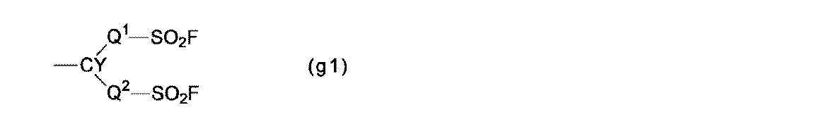
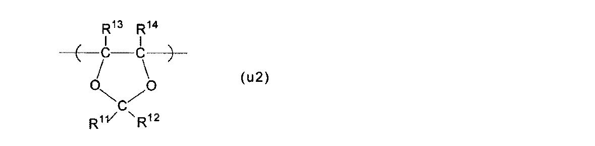
- Polymer (F) a structural unit (A) based on a perfluoromonomer having a precursor group represented by the following formula (g1), a structural unit (B) represented by the following formula (u2), and tetrafluoroethylene
- the proportion of the structural unit (A) is 8 to 19 mol% and the proportion of the structural unit (B) is 65 to 80% of 100 mol% of all the structural units.
- a polymer in which the proportion of the structural unit (C) is 1 to 27 mol%.
- Q 1 is a good perfluoroalkylene group which may have an etheric oxygen atom
- Q 2 is a single bond, or an ether bonding oxygen atom good perfluoroalkylene group which may have a
- Y is , A fluorine atom or a monovalent perfluoro organic group.
- R 11 and R 12 are each independently a fluorine atom or a C 1-5 perfluoroalkyl group
- R 13 and R 14 are each independently a fluorine atom, a C 1-5 perfluoroalkyl group, Or a perfluoroalkoxy group having 1 to 5 carbon atoms.
- TQ value A temperature at which the extrusion amount becomes 100 mm 3 / sec when the polymer (F) is melt-extruded under the condition of an extrusion pressure of 2.94 MPa using a nozzle having a length of 1 mm and an inner diameter of 1 mm.
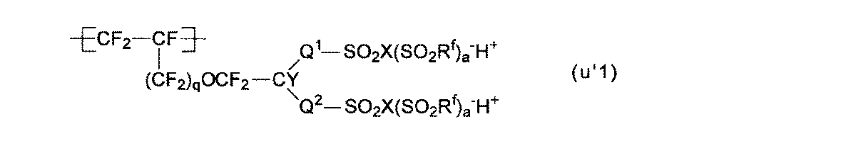
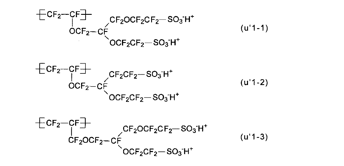
- At least one of the structural units (A ′) obtained by converting the precursor group of the structural unit (A) into an ion exchange group is a structural unit represented by the following formula (u′1): The electrolyte material according to any one of [4].
- Rf is a perfluoroalkyl group which may have an ether bond oxygen atom
- X is an oxygen atom, a nitrogen atom, or a carbon atom
- a 0,
- X is a nitrogen atom
- a 1
- X is a carbon atom
- a 2
- q is 0 or 1.
- a liquid composition comprising a dispersion medium and the electrolyte material of any one of [1] to [8] dispersed in the dispersion medium, wherein the dispersion medium comprises an organic solvent having a hydroxyl group.
- the liquid composition according to [9] comprising 1 to 50% by mass of the electrolyte material according to any one of [1] to [8].
- anode having a catalyst layer containing a proton conductive polymer, a cathode having a catalyst layer containing a proton conductive polymer, and a solid polymer electrolyte membrane disposed between the anode and the cathode
- the proton conductive polymer contained in at least one of the catalyst layer of the cathode and the anode is an electrolyte material of any one of [1] to [8]
- the membrane / electrode assembly using the electrolyte material of the present invention for the catalyst layer can exhibit excellent power generation characteristics (such as output voltage) in a wide temperature range and a wide humidity range.
- excellent power generation characteristics such as output voltage
- Excellent power generation characteristics output voltage, etc.
- the ratio of the structural unit (A) in the polymer (F) is decreased to lower the ion exchange capacity of the polymer (H) to improve the power generation characteristics under low temperature and high humidity conditions, The power generation characteristics under the conditions are reduced.
- the structural unit (u2) is selected as a structural unit based on a perfluoromonomer having a five-membered ring, and the proportion of each structural unit is set to a specific range, so that it can be used under high temperature and low humidity conditions. It is estimated that the decrease in power generation characteristics could be suppressed.
- the structural unit represented by the formula (u1) is referred to as the structural unit (u1).
- the constitutional units represented by other formulas are also described accordingly.
- the monomer represented by the formula (m1) is referred to as a monomer (m1).
- Monomers represented by other formulas are also described in the same manner.
- a group represented by the formula (g1) is referred to as a group (g1).
- Groups represented by other formulas are also described in the same manner.
- Fluorine-containing polymer means a polymer in which some or all of hydrogen atoms bonded to carbon atoms are substituted with fluorine atoms.
- Structuretural unit means a unit derived from a monomer formed by polymerization of the monomer. The structural unit may be a unit directly formed by a polymerization reaction of monomers, or may be a unit in which a part of the unit is converted into another structure by treating the polymer.
- Perfluoromonomer means a monomer in which all of hydrogen atoms bonded to carbon atoms are substituted with fluorine atoms.
- an “ion exchange group” is a group having H + , a monovalent metal cation, an ammonium ion, or the like.
- Examples of the ion exchange group include a sulfonic acid group, a sulfonimide group, and a sulfonemethide group.
- the “precursor group” means a group that can be converted into an ion exchange group by a known treatment such as hydrolysis treatment or acidification treatment. Examples of the precursor group include —SO 2 F group.
- the electrolyte material of the present invention comprises a polymer (H) obtained by converting a precursor group of the polymer (F) into an ion exchange group.
- a polymer (F) is a polymer which has a specific structural unit (A), a specific structural unit (B), a specific structural unit (C), and another structural unit (D) as needed. .
- the structural unit (A) is a structural unit based on a perfluoromonomer having a group (g1) which is a precursor group of an ion exchange group.
- Q 1 is a perfluoroalkylene group which may have an etheric oxygen atom.
- Q 2 is a perfluoroalkylene group which may have a single bond or an ether bond oxygen atom.
- the oxygen atom may be one or two or more.
- the oxygen atom may be inserted between the carbon atom-carbon atom bonds of the perfluoroalkylene group or may be inserted at the carbon atom bond terminal.
- the perfluoroalkylene group may be linear or branched, and is preferably linear.
- the perfluoroalkylene group preferably has 1 to 6 carbon atoms, and more preferably 1 to 4 carbon atoms. If the number of carbon atoms is 6 or less, the boiling point of the raw material monomer (a) becomes low, and distillation purification becomes easy. Moreover, if carbon number is 6 or less, the fall of the ion exchange capacity of a polymer (H) will be suppressed, and the fall of proton conductivity will be suppressed.
- Q 2 is preferably a C 1-6 perfluoroalkylene group which may have an etheric oxygen atom.
- Q 2 is a perfluoroalkylene group having 1 to 6 carbon atoms which may have an etheric oxygen atom
- the solid polymer fuel cell is operated for a longer period of time than when Q 2 is a single bond.
- it has excellent power generation characteristics.
- At least one of Q 1 and Q 2 is preferably a C 1-6 perfluoroalkylene group having an etheric oxygen atom. Since the monomer (a) having a C 1-6 perfluoroalkylene group having an etheric oxygen atom can be synthesized without undergoing a fluorination reaction with a fluorine gas, the yield is good and the production is easy.
- Y is a fluorine atom or a monovalent perfluoro organic group.
- Y is preferably a fluorine atom or a linear perfluoroalkyl group having 1 to 6 carbon atoms which may have an etheric oxygen atom.
- the structural unit (u1) is preferable because the membrane electrode assembly can exhibit better power generation characteristics even under low temperature and high humidity conditions, and also under high temperature and low humidity conditions.
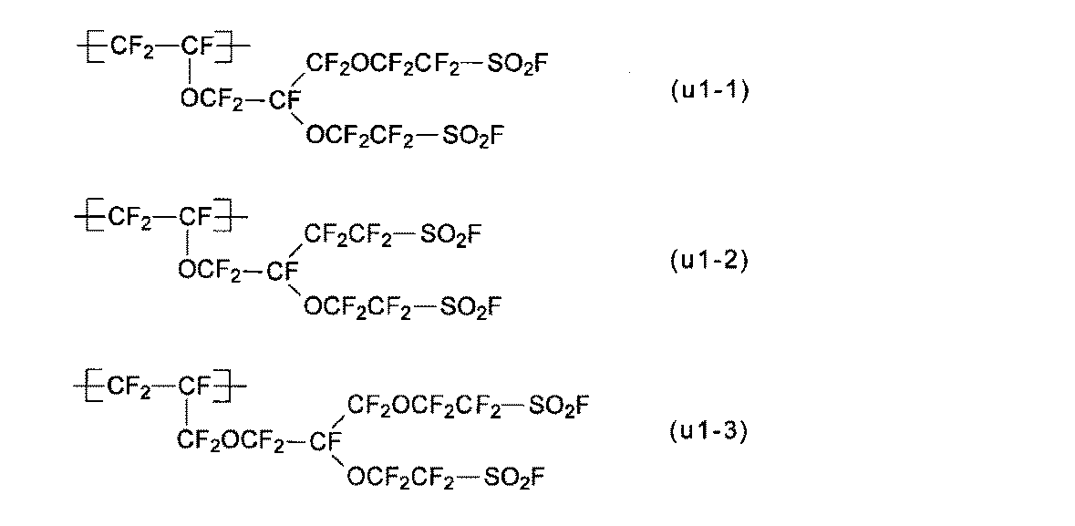
- Q 1 , Q 2 and Y are as described for the group (g1). q is 0 or 1.
- the structural units (u1-1) to (u1-3) are preferable because the production of the polymer (H) is easy and industrial implementation is easy. 1) is particularly preferred.
- Structural unit (B) The structural unit (B) is the structural unit (u2).
- R 11 and R 12 are each independently a fluorine atom or a perfluoroalkyl group having 1 to 5 carbon atoms.
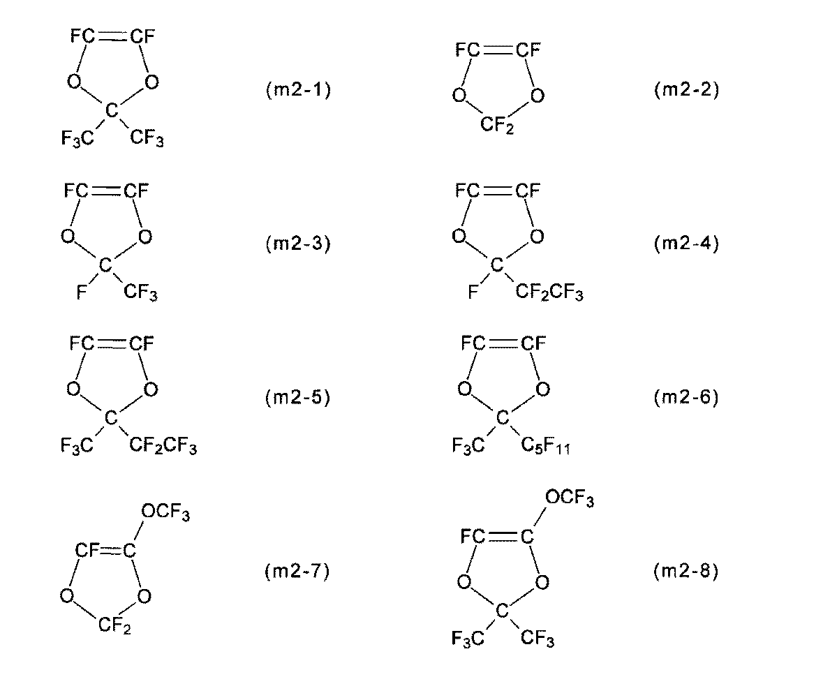
- R 13 and R 14 are each independently a fluorine atom, a C 1-5 perfluoroalkyl group, or a C 1-5 perfluoroalkoxy group. At least one of R 13 and R 14 is preferably a fluorine atom, and more preferably both are fluorine atoms, from the viewpoint of high polymerization reactivity of the monomer (m2) described later.
- the perfluoroalkyl group and the perfluoroalkoxy group may be linear or branched, and preferably linear.
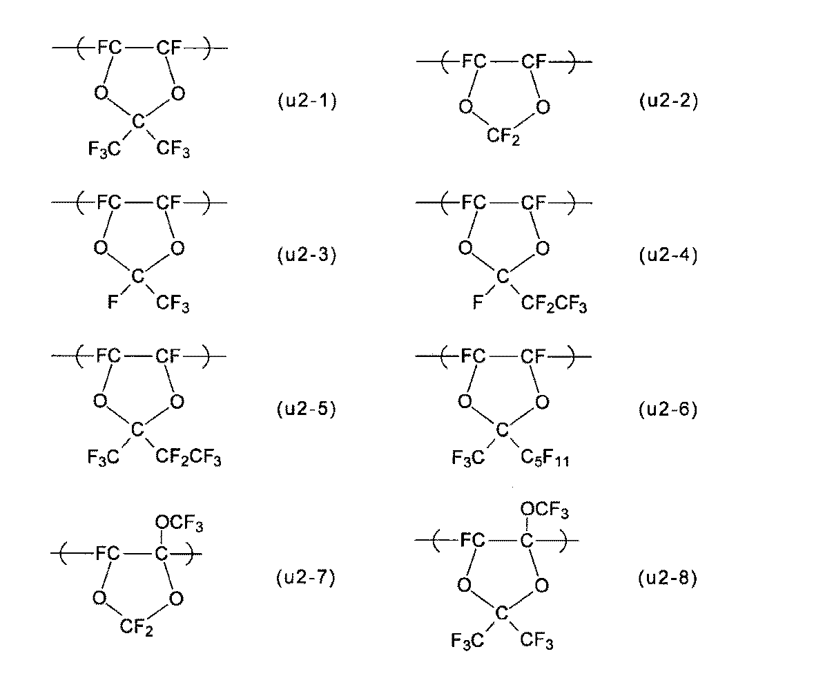
- Examples of the structural unit (u2) include the structural units (u2-1) to (u2-8), and the membrane electrode assembly is more excellent in power generation even under low temperature and high humidity conditions, and at high temperature and low humidity conditions.
- the structural unit (u2-1) is particularly preferable from the viewpoint of exhibiting characteristics.
- the structural unit (C) is a structural unit based on tetrafluoroethylene.
- the other structural unit (D) is a structural unit based on another monomer (d) described later.
- the proportion of the structural unit (A) is 8 to 19 mol%, more preferably 13 to 18 mol%, more preferably 14 to 18 mol%, out of 100 mol% of all the structural units constituting the polymer (F). preferable.
- the proportion of the structural unit (A) is at least the lower limit, the solubility or dispersibility of the polymer (H) is improved, and a liquid composition described later can be easily prepared.
- the proportion of the structural unit (A) is less than or equal to the above upper limit value, the flooding phenomenon in the catalyst layer is suppressed, and the membrane electrode assembly can exhibit excellent power generation characteristics even under low temperature and high humidity conditions.
- the proportion of the structural unit (B) is 65 to 80 mol%, more preferably 67 to 78 mol%, more preferably 68 to 75 mol%, out of 100 mol% of all the structural units constituting the polymer (F). preferable.
- the proportion of the structural unit (B) is at least the lower limit, the membrane / electrode assembly can exhibit excellent power generation characteristics even under high temperature and low humidity conditions. If the proportion of the structural unit (B) is less than or equal to the above upper limit, the glass transition point of the polymer is not too high, the flooding phenomenon in the catalyst layer is suppressed, and the membrane electrode assembly is excellent even under low temperature and high humidity conditions. Power generation characteristics can be expressed.
- the proportion of the structural unit (C) is 1 to 27 mol%, preferably 4 to 20 mol%, more preferably 7 to 18 mol%, out of 100 mol% of all the structural units constituting the polymer (F). preferable.
- the proportion of the structural unit (C) is at least the lower limit, crystallinity due to tetrafluoroethylene can be imparted and the mechanical strength is excellent.
- the proportion of the structural unit (C) is not more than the above upper limit, the solubility or dispersibility of the polymer (H) is improved, and a liquid composition described later can be easily prepared.
- the proportion of the other structural unit (D) is preferably 30 mol% or less, more preferably 15 mol% or less, even more preferably 10 mol% or less, out of 100 mol% of all the structural units constituting the polymer (F). . If the proportion of the other structural unit (D) is equal to or less than the upper limit value, it is difficult to impair the effects of the present invention.
- the TQ value of polymer (F) is preferably 250 to 330 ° C, more preferably 255 to 300 ° C, and further preferably 260 to 290 ° C.
- the TQ value of the polymer (F) is at least the lower limit, the polymer (H) has a sufficient molecular weight and is excellent in mechanical strength.
- the TQ value of the polymer (F) is not more than the above upper limit value, the solubility or dispersibility of the polymer (H) is improved, and a liquid composition described later can be easily prepared.
- the TQ value is an index of the molecular weight of the polymer.
- the extrusion amount when the polymer (F) is melt-extruded under the condition of the extrusion pressure of 2.94 MPa using a nozzle having a length of 1 mm and an inner diameter of 1 mm is 100 mm 3 / This is the temperature in seconds.
- the polymer (F) is produced by polymerizing a specific monomer (a), a specific monomer (b), a specific monomer (c), and, if necessary, another monomer (d).
- the monomer (a) is a perfluoromonomer having a group (g1).
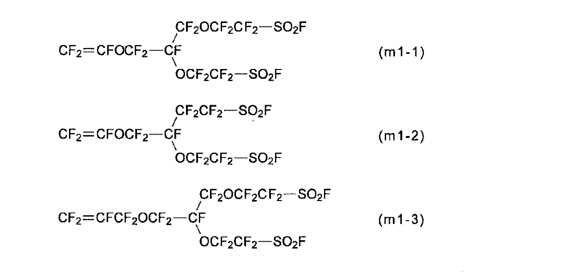
- the monomer (m1) is preferable because the membrane / electrode assembly can exhibit better power generation characteristics even under low temperature and high humidity conditions, and also under high temperature and low humidity conditions.
- the monomers (m1-1) to (m1-3) are preferable because the production of the polymer (H) is easy and the industrial implementation is easy, and the monomer (m1-1) is preferably Particularly preferred.
- the monomer (m1) can be synthesized by a method described in International Publication No. 2007/013533, Japanese Patent Application Laid-Open No. 2008-202039, or the like.
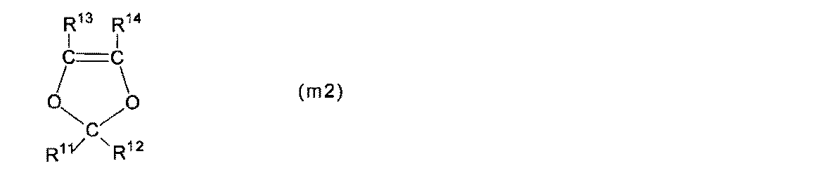
- Monomer (b) is monomer (m2).
- R 11 to R 14 are as described for the structural unit (u2).
- Examples of the monomer (m2) include monomers (m2-1) to (m2-8), and the membrane / electrode assembly has superior power generation characteristics even under low temperature and high humidity conditions, and even under high temperature and low humidity conditions. From the viewpoint of expression, the monomer (m2-1) is particularly preferable.
- Compound (m2) is described in Macromolecule, Vol. 26, No. 22, 1993, p. 5829-5834; can be synthesized by the method described in JP-A-6-92957.
- Monomer (c) is tetrafluoroethylene.
- the other monomer (d) is a monomer other than the monomer (a), the monomer (b), and the monomer (c).
- Other monomers (d) include chlorotrifluoroethylene, trifluoroethylene, vinylidene fluoride, vinyl fluoride, ethylene, propylene, perfluoro (3-butenyl vinyl ether), perfluoro (allyl vinyl ether), perfluoro ⁇ -olefins (Hexafluoropropylene, etc.), (perfluoroalkyl) ethylenes ((perfluorobutyl) ethylene, etc.), (perfluoroalkyl) propenes (3-perfluorooctyl-1-propene, etc.), perfluoro (alkyl vinyl ethers), the following monomers (M3), a perfluoromonomer having a 5-membered ring described in Patent Document 1 (excluding the monomer (m2)), and a perfluoromonomer capable of
- Q is a perfluoroalkylene group which may have a single bond or an ether bond oxygen atom
- Z is a fluorine atom or a monovalent perfluoroorganic group
- s is 0 or 1.
- Monomer polymerization examples include known polymerization methods such as a bulk polymerization method, a solution polymerization method, a suspension polymerization method, and an emulsion polymerization method. Moreover, you may superpose
- radical initiator examples include bis (fluoroacyl) peroxides, bis (chlorofluoroacyl) peroxides, dialkyl peroxydicarbonates, diacyl peroxides, peroxyesters, azo compounds, persulfates, and the like.
- Perfluoro compounds such as bis (fluoroacyl) peroxides are preferred from the viewpoint of obtaining a polymer (F) having few unstable terminal groups.
- Solvents include perfluorotrialkylamines (perfluorotributylamine, etc.), perfluorocarbons (perfluorohexane, perfluorooctane, etc.), hydrofluorocarbons (1H, 4H-perfluorobutane, 1H-perfluorohexane, etc.), hydrochlorofluorocarbons (3,3-dichloro-1,1,1,2,2-pentafluoropropane, 1,3-dichloro-1,1,2,2,3-pentafluoropropane, etc.), hydrofluoroethers (CF 3 CH 2 OCF 2 CF 2 H, etc.).
- a monomer, a radical initiator, and the like are added to a solvent, and radicals are generated in the solvent to polymerize the monomer.
- the monomer and initiator may be added all at once, sequentially, or continuously.
- Nonionic radical initiators include bis (fluoroacyl) peroxides, bis (chlorofluoroacyl) peroxides, dialkyl peroxydicarbonates, diacyl peroxides, peroxyesters, dialkyl peroxides, bis (fluoroalkyl) Examples thereof include peroxides and azo compounds.
- the dispersion medium may contain the above-mentioned solvent as an auxiliary agent; a surfactant as a dispersion stabilizer that prevents aggregation of suspended particles; and a hydrocarbon compound (hexane, methanol, etc.) as a molecular weight regulator.
- a surfactant as a dispersion stabilizer that prevents aggregation of suspended particles
- a hydrocarbon compound hexane, methanol, etc.
- the polymer (H) is a polymer obtained by converting a precursor group of the polymer (F) into an ion exchange group, and includes a specific structural unit (A ′), a specific structural unit (B), and a specific structural unit (C ) And, if necessary, another structural unit (D).
- the structural unit (A ′) is a structural unit obtained by converting the precursor group of the structural unit (A) into an ion exchange group.
- the ion exchange group is preferably a group (g′1).
- R f is a linear or branched perfluoroalkyl group which may have an etheric oxygen atom.
- the perfluoroalkyl group preferably has 1 to 8 carbon atoms, and more preferably 1 to 6 carbon atoms.
- R f may be the same group or different groups.
- the structural unit (u′1) is preferable because the membrane electrode assembly can exhibit better power generation characteristics even under low temperature and high humidity conditions, and also under high temperature and low humidity conditions.
- the structural units (u′1) to (u′1-3) are preferable from the viewpoint of easy production of the polymer (H) and easy industrial implementation.
- the structural unit (u′1-1) is particularly preferable.
- the structural unit (B) is as described in the polymer (F).
- the structural unit (C) is as described in the polymer (F).
- the other structural unit (D) is as described in the polymer (F).
- the precursor group of the structural unit is converted into an ion exchange group when the polymer (H) is produced.
- the ion exchange capacity of the polymer (H) is preferably 0.7 to 1.29 meq / g dry resin, more preferably 0.93 to 1.23 meq / g dry resin, and 1.03 to 1.23. More preferred are milliequivalents / g dry resin.
- the ion exchange capacity is equal to or higher than the lower limit, the conductivity of the polymer (H) is increased. Therefore, when the ion exchange capacity is used as the electrolyte material of the catalyst layer of the polymer electrolyte fuel cell, a sufficient output voltage can be obtained.
- the ion exchange capacity is not more than the above upper limit value, the flooding phenomenon in the catalyst layer is further suppressed, and the membrane electrode assembly can exhibit further excellent power generation characteristics even under low temperature and high humidity conditions.
- the polymer (H) is produced by converting the precursor group of the polymer (F) into an ion exchange group.
- -SO 2 F groups sulfonic acid groups - as a way to convert (-SO 3 H + group) include the following methods (i), a -SO 2 F group sulfonimide group (-SO 2 N ( As a method for converting into (SO 2 R f ) ⁇ H + group), the following method (ii) may be mentioned.
- IIi A method in which the —SO 2 F group of the polymer (F) is imidized to form a salt type sulfonimide group, and further converted to an acid type to convert to an acid type sulfonimide group.
- the basic compound include sodium hydroxide and potassium hydroxide.
- the solvent include water, a mixed solvent of water and a polar solvent, and the like.
- the polar solvent include alcohols (methanol, ethanol, etc.), dimethyl sulfoxide and the like.
- the acidification is performed, for example, by bringing a polymer having a sulfonate into contact with an aqueous solution such as hydrochloric acid or sulfuric acid. Hydrolysis and acidification are usually performed at 0 to 120 ° C.
- (Ii-1) A method of reacting —SO 2 F group with R f SO 2 NHM.
- (Ii-2) A method of reacting —SO 2 F group with R f SO 2 NH 2 in the presence of alkali metal hydroxide, alkali metal carbonate, MF, ammonia or primary to tertiary amine.
- (Ii-3) A method of reacting a —SO 2 F group with R f SO 2 NMSi (CH 3 ) 3 .
- M is an alkali metal or primary to quaternary ammonium. Acidification is carried out by treating a polymer having a salt-type sulfonimide group with an acid (sulfuric acid, nitric acid, hydrochloric acid, etc.).
- the liquid composition of the present invention is a composition comprising a dispersion medium and the electrolyte material of the present invention dispersed in the dispersion medium.
- the dispersion medium contains an organic solvent having a hydroxyl group.
- the organic solvent having a hydroxyl group include methanol, ethanol, 1-propanol, 2-propanol, 2,2,2-trifluoroethanol, 2,2,3,3,3-pentafluoro-1-propanol, 2,2 , 3,3-tetrafluoro-1-propanol, 4,4,5,5,5-pentafluoro-1-pentanol, 1,1,1,3,3,3-hexafluoro-2-propanol, 3, , 3,3-trifluoro-1-propanol, 3,3,4,4,5,5,6,6,6-nonafluoro-1-hexanol, 3,3,4,4,5,5,6 6,7,7,8,8,8-tridecafluoro-1-octanol and the like.
- the organic solvent which has a hydroxyl group may be used individually by 1 type, and 2 or more types may be mixed and used for it.
- the dispersion medium preferably contains water.
- the proportion of water is preferably 10 to 99% by mass and more preferably 40 to 99% by mass in the dispersion medium (100% by mass). By increasing the proportion of water, the dispersibility of the electrolyte material in the dispersion medium can be improved.
- the proportion of the organic solvent having a hydroxyl group is preferably 1 to 90% by mass and more preferably 1 to 60% by mass in the dispersion medium (100% by mass).
- the ratio of the electrolyte material is preferably 1 to 50% by mass and more preferably 3 to 30% by mass in the liquid composition (100% by mass).
- a specific method for preparing the liquid composition there is a method in which shearing such as stirring is applied to the electrolyte material in the dispersion medium under atmospheric pressure or in a state sealed with an autoclave or the like.
- the preparation temperature is preferably 0 to 250 ° C, more preferably 20 to 150 ° C. You may provide shearing, such as an ultrasonic wave, as needed.
- a liquid mixture in which an electrolyte material, an organic solvent and water are mixed is subjected to shearing such as stirring to obtain a liquid composition
- the liquid mixture in which the organic solvent and water are added all at once to the electrolyte material is stirred.
- Shear may be applied, or an organic solvent or water may be mixed into the electrolyte material in a plurality of times, and shearing such as stirring may be applied between them.
- a shearing solution such as stirring is added to a mixed solution obtained by adding a part of an organic solvent and a part of water to the electrolyte material, and then the remaining organic solvent or water is added to the mixed solution and then shearing such as stirring is performed again. You may make it add.
- liquid composition of the present invention is suitably used for forming a catalyst layer in a membrane electrode assembly described later.
- FIG. 1 is a schematic cross-sectional view of an example of a membrane electrode assembly for a polymer electrolyte fuel cell of the present invention (hereinafter referred to as a membrane electrode assembly).
- the membrane electrode assembly 10 is in contact with the catalyst layer 11 between the anode 13 having the catalyst layer 11 and the gas diffusion layer 12, the cathode 14 having the catalyst layer 11 and the gas diffusion layer 12, and the anode 13 and the cathode 14. And a solid polymer electrolyte membrane 15 arranged in the above state.
- the catalyst layer 11 is a layer containing a catalyst and a proton conductive polymer.
- the catalyst include a supported catalyst in which platinum or a platinum alloy is supported on a carbon support.
- the carbon carrier include carbon black powder.
- Examples of the proton conductive polymer include the electrolyte material of the present invention or a known electrolyte material, and the proton conductive polymer contained in at least one of the catalyst layers of the cathode and the anode is the electrolyte material of the present invention. More preferably, the proton conductive polymer contained in the catalyst layer of the cathode is the electrolyte material of the present invention.
- the catalyst layer 11 may contain a water repellent agent from the viewpoint of increasing the effect of suppressing the flooding phenomenon.
- the water repellent include tetrafluoroethylene-hexafluoropropylene copolymer, tetrafluoroethylene-perfluoro (alkyl vinyl ether) copolymer, polytetrafluoroethylene and the like.
- a fluorine-containing polymer that can be dissolved in a solvent is preferable because the catalyst layer 11 can be easily subjected to water repellent treatment.
- the amount of the water repellent agent is preferably 0.01 to 30% by mass, more preferably 0.05 to 10% by mass in the catalyst layer 11 (100% by mass).
- Examples of the method for forming the catalyst layer 11 include the following methods.
- the catalyst layer forming liquid is a liquid in which an electrolyte material and a catalyst are dispersed in a dispersion medium.
- the catalyst layer forming liquid can be prepared, for example, by mixing the liquid composition of the present invention and a catalyst dispersion.
- the gas diffusion layer 12 has a function of uniformly diffusing gas in the catalyst layer 11 and a function as a current collector.
- Examples of the gas diffusion layer 12 include carbon paper, carbon cloth, and carbon felt.
- the gas diffusion layer 12 is preferably water repellent treated with polytetrafluoroethylene or the like.
- the membrane electrode assembly 10 may have a carbon layer 16 between the catalyst layer 11 and the gas diffusion layer 12, as shown in FIG. By disposing the carbon layer 16, the gas diffusibility on the surface of the catalyst layer 11 is improved, and the power generation characteristics of the membrane electrode assembly 10 are greatly improved.
- the carbon layer 16 is a layer containing carbon and a nonionic fluorine-containing polymer.
- carbon carbon nanofibers having a fiber diameter of 1 to 1000 nm and a fiber length of 1000 ⁇ m or less are preferable.
- the nonionic fluorine-containing polymer include polytetrafluoroethylene.
- the solid polymer electrolyte membrane 15 is a membrane containing a proton conductive polymer.
- the proton conductive polymer include the electrolyte material of the present invention or a known electrolyte material.
- Known electrolyte materials include a polymer having a structural unit based on the monomer (m3) and a structural unit based on TFE, a polymer obtained by converting —SO 2 F groups into sulfonic acid groups; a structural unit based on the monomer (m1) and TFE And a polymer obtained by converting —SO 2 F group of a polymer having a structural unit based on the above to a sulfonic acid group.
- the solid polymer electrolyte membrane 15 can be formed by, for example, a method (cast method) in which a liquid composition of an electrolyte material is applied on a base film or the catalyst layer 11 and dried.
- the liquid composition is a dispersion in which an electrolyte material is dispersed in a dispersion medium containing an organic solvent having a hydroxyl group and water.
- the temperature of the heat treatment is preferably 130 to 200 ° C., more preferably 150 to 180 ° C., although it depends on the type of electrolyte material.
- the temperature of the heat treatment is 130 ° C. or higher, the electrolyte material does not excessively contain water. If the temperature of the heat treatment is 200 ° C. or less, thermal decomposition of the ion exchange groups is suppressed, and a decrease in proton conductivity of the solid polymer electrolyte membrane 15 is suppressed.
- the solid polymer electrolyte membrane 15 may be treated with a hydrogen peroxide solution as necessary.
- the solid polymer electrolyte membrane 15 may be reinforced with a reinforcing material.
- the reinforcing material include porous bodies, fibers, woven fabrics, and nonwoven fabrics.
- the reinforcing material include polytetrafluoroethylene, tetrafluoroethylene-hexafluoropropylene copolymer, tetrafluoroethylene-perfluoro (alkyl vinyl ether) copolymer, polyethylene, polypropylene, polyphenylene sulfide, and the like.
- the solid polymer electrolyte membrane 15 may contain one or more atoms selected from the group consisting of cerium and manganese in order to further improve the durability. Cerium and manganese decompose hydrogen peroxide, which is a causative substance that causes deterioration of the solid polymer electrolyte membrane 15. Cerium and manganese are preferably present as ions in the solid polymer electrolyte membrane 15, and may exist in any state in the solid polymer electrolyte membrane 15 as long as they are present as ions.
- the solid polymer electrolyte membrane 15 may contain silica or a heteropolyacid (zirconium phosphate, phosphomolybdic acid, phosphotungstic acid, etc.) as a water retention agent for preventing drying.
- the membrane electrode assembly 10 is manufactured, for example, by the following method.
- the membrane electrode assembly 10 is manufactured by the following method, for example.
- a dispersion containing carbon and a nonionic fluorine-containing polymer is applied on a base film and dried to form a carbon layer 16.
- a catalyst layer 11 is formed on the carbon layer 16.
- the solid polymer electrolyte membrane 15 are bonded together, the base film is peeled off to form a membrane catalyst layer assembly having the carbon layer 16, and the membrane catalyst layer assembly is sandwiched between the gas diffusion layers 12.
- a dispersion containing carbon and a nonionic fluoropolymer was applied on the gas diffusion layer 12 and dried to form the carbon layer 16, and the catalyst layer 11 was formed on the solid polymer electrolyte membrane 15.
- a method in which a membrane catalyst layer assembly is sandwiched between gas diffusion layers 12 each having a carbon layer 16.
- the membrane electrode assembly of the present invention is used for a polymer electrolyte fuel cell.
- a polymer electrolyte fuel cell is manufactured, for example, by forming a cell by sandwiching a membrane electrode assembly between two separators and stacking a plurality of cells.
- Examples of the separator include a conductive carbon plate in which a groove serving as a passage for an oxidant gas (air, oxygen, etc.) containing fuel gas or oxygen is formed.
- Examples of the polymer electrolyte fuel cell include a hydrogen / oxygen fuel cell and a direct methanol fuel cell (DMFC).
- the methanol or methanol aqueous solution used for the DMFC fuel may be a liquid feed or a gas feed.
- Examples 1 to 5 and 11 to 15 are examples, and examples 6 to 10, 16 to 18, and 20 are comparative examples.
- TQ value Using a flow tester CFT-500A (manufactured by Shimadzu Corp.) equipped with a nozzle with a length of 1 mm and an inner diameter of 1 mm, the extrusion amount of the polymer (F) was measured by changing the temperature under the extrusion pressure of 2.94 MPa. was determined to be a temperature (TQ value) at which 100 mm 3 / sec.
- the polymer (H) was placed in a glove box and left to dry in an atmosphere of flowing dry nitrogen at room temperature for 24 hours. The dry mass of the polymer (H) was measured in the glove box.
- the polymer (H) was immersed in a 2 mol / L sodium chloride aqueous solution, allowed to stand at 60 ° C. for 1 hour, and then cooled to room temperature.
- the aqueous sodium chloride solution in which the polymer (H) was immersed was titrated with a 0.5 mol / L aqueous sodium hydroxide solution to determine the ion exchange capacity of the polymer (H).
- BSVE-2E monomer (m1-1), PDD: monomer (m2-1), TFE: tetrafluoroethylene, PSVE: monomer (m3-1), MMD: monomer (m4-1).
- Example 1 A stainless steel autoclave with an internal volume of 2575 mL was charged with 1076 g of BSVE-2E under reduced pressure while being cooled with ice water, and deaerated. 328 g of PDD was charged. After raising the temperature to 24 ° C., 0.1 MPa of nitrogen gas was introduced. After confirming that the pressure did not change, 54.0 g of TFE was charged. After adding 13.64 g of a 3.1 mass% solution of PFB dissolved in C6H with nitrogen gas, the addition line was washed with 4 g of C6H. 24 hours after the start of the polymerization, the autoclave was cooled to stop the polymerization reaction, and the gas in the system was purged to obtain a polymer (F-1) solution.
- the yield of polymer (F-1) is shown in Table 1.
- Table 2 shows the proportion of each structural unit of the polymer (F-1) and the TQ value.
- a mixed dispersion medium of 1-propanol / water 50/50 (mass ratio) was added to the polymer (H-1), the solid content concentration was adjusted to 8 mass%, and the mixture was stirred at 105 ° C. for 8 hours using an autoclave.
- Example 2 A stainless steel autoclave having an internal volume of 230 mL was charged with 94.26 g of BSVE-2E and 35.48 g of PDD, and sufficiently freeze-deaerated with liquid nitrogen. 3.90 g of TFE was charged and the temperature was raised to 28 ° C. After confirming that the pressure did not change, 0.1 MPa of nitrogen gas was introduced. After adding 1.26 g of a 3.1 wt% solution of PFB dissolved in C6H with nitrogen gas, the addition line was washed with 2 g of C6H. After stirring for 24 hours from the start of polymerization, the autoclave was cooled to stop the reaction, and the gas in the system was purged to obtain a polymer (F-2) solution.
- the yield of polymer (F-2) is shown in Table 1.
- Table 2 shows the proportion and TQ value of each structural unit of the polymer (F-2).
- polymer (H-2) was obtained from polymer (F-2).
- Table 2 shows the ion exchange capacity of the polymer (H-2).
- a liquid composition (L-2) was obtained from the polymer (H-2).
- Example 5 Polymers (F-3), (F-4), and (F-5) are obtained in the same manner as in Example 2 except that the amount charged and the temperature are changed as shown in Table 1. The yields of the polymers (F-3), (F-4) and (F-5) are shown in Table 1. Table 2 shows the proportions and TQ values of the structural units of the polymers (F-3), (F-4), and (F-5).
- Example 2 shows the ion exchange capacities of the polymers (H-3), (H-4), and (H-5).
- liquid compositions (L-3), (L-4) and (L-5) are obtained from the polymers (H-3), (H-4) and (H-5).
- Example 6 A stainless steel autoclave with an internal volume of 125 mL is charged with 11.71 g of PDD, 95.15 g of BSVE-2E and 33 mg of IPP, and sufficiently deaerated under cooling with liquid nitrogen. Charge 0.6 g of TFE, raise the temperature to 40 ° C., and stir for 18 hours. The reaction is stopped by cooling the autoclave to obtain a solution of polymer (F-6).
- polymer (H-6) is obtained from polymer (F-6).
- Table 2 shows the ion exchange capacity of the polymer (H-6).
- a liquid composition (L-6) is obtained from the polymer (H-6).
- Example 7 A stainless steel autoclave having an internal volume of 125 mL is charged with 24.0 g of PDD, 79.0 g of BSVE-2E, 18 g of 225 cb, and 54.0 mg of IPP, and sufficiently deaerated under cooling with liquid nitrogen. 5.8 g of TFE is introduced into the system, and the temperature is raised to 40 ° C. After stirring at 40 ° C. for 21 hours, the gas in the system is purged, the autoclave is returned to room temperature, and a solution of polymer (F-7) is obtained.
- polymer (H-7) is obtained from polymer (F-7).
- Table 2 shows the ion exchange capacity of the polymer (H-7).
- a liquid composition (L-7) is obtained from the polymer (H-7).
- Example 8 A polymer (F-8) is obtained in the same manner as in Example 7 except that the charging amount and temperature are changed as shown in Table 1. The yield of polymer (F-8) is shown in Table 1. Table 2 shows the proportion and TQ value of each structural unit of the polymer (F-8).
- polymer (H-8) is obtained from polymer (F-8).
- Table 2 shows the ion exchange capacity of the polymer (H-8).
- liquid composition (L-8) is obtained from the polymer (H-8).
- Example 9 A polymer (F-9) is obtained in the same manner as in Example 7, except that the charging amount and temperature are changed as shown in Table 1. The yield of polymer (F-9) is shown in Table 1. Table 2 shows the proportion and TQ value of each structural unit of the polymer (F-9).
- Example 7 the polymer (H-9) is obtained from the polymer (F-9).
- Table 2 shows the ion exchange capacity of the polymer (H-9).
- an attempt was made to obtain a liquid composition but the polymer (H-9) was not dispersed in the dispersion medium and remained as a solid, and no liquid composition was obtained.
- Example 10 A polymer (F-10) is obtained in the same manner as in Example 7 except that PDD is changed to MMD and the charging amount and temperature are changed as shown in Table 1. The yield of polymer (F-10) is shown in Table 1. Table 2 shows the proportion and TQ value of each structural unit of the polymer (F-10).
- polymer (H-10) is obtained from polymer (F-10).
- Table 2 shows the ion exchange capacity of the polymer (H-10).
- liquid composition (L-10) is obtained from the polymer (H-10).
- BSVE-E, PSVE and TFE were polymerized in the same manner as described in Example 5 on page 29 of WO2008 / 090990 to obtain a polymer (F ′).
- the —SO 2 F group of the polymer (F ′) was converted to a sulfonic acid group to obtain a polymer (H ′).
- the ion exchange capacity of the polymer (H ′) was 1.5 meq / g dry resin.
- the liquid composition (L ′) was applied to the surface of a sheet made of an ethylene-TFE copolymer (Asahi Glass Co., Aflex (registered trademark) 100N, thickness 100 ⁇ m) (hereinafter referred to as an ETFE sheet) with a die coater. It was applied, dried at 80 ° C. for 30 minutes, and further subjected to heat treatment at 185 ° C. for 30 minutes to obtain a solid polymer electrolyte membrane having a thickness of 20 ⁇ m.
- an ethylene-TFE copolymer Asahi Glass Co., Aflex (registered trademark) 100N, thickness 100 ⁇ m
- Example 11 39 g of water was added to 10 g of a supported catalyst in which 50% by mass of platinum was supported on carbon powder, and ultrasonic waves were applied for 10 minutes to obtain a catalyst dispersion.
- 60 g of the liquid composition (L-1) was added, and 64 g of ethanol was further added to adjust the solid content concentration to 8% by mass to obtain a catalyst layer forming solution.
- the liquid was applied to the surface of a separately prepared ETFE sheet, dried at 80 ° C. for 30 minutes, and further subjected to heat treatment at 160 ° C. for 30 minutes to form a catalyst layer having a platinum amount of 0.2 mg / cm 2 .
- the solid polymer electrolyte membrane After peeling the ETFE sheet from the solid polymer electrolyte membrane produced above, the solid polymer electrolyte membrane is sandwiched between two catalyst layers with an ETFE sheet, and the press temperature is 160 ° C., the press time is 5 minutes, and the pressure is 3 MPa. Heat-pressed, the catalyst layer produced above was joined to both surfaces of the solid polymer electrolyte membrane, the ETFE sheet was peeled from the catalyst layer, and a membrane catalyst layer assembly having an electrode area of 25 cm 2 was obtained. A carbon layer made of carbon and polytetrafluoroethylene was formed on the surface of the gas diffusion layer made of carbon paper.
- the membrane / catalyst layer assembly was sandwiched between the gas diffusion layers so that the carbon layer and the catalyst layer were in contact with each other to obtain a membrane / electrode assembly.
- the membrane electrode assembly was incorporated into a power generation cell, and power generation characteristics were evaluated. The results are shown in Table 2.
- Example 16 and Example 16 except that the liquid composition (L-1) used for forming the catalyst layer was changed to liquid compositions (L-2) to (L-18) or (L-20), respectively.
- a membrane electrode assembly is produced by the same method, and the power generation characteristics are evaluated. The results are shown in Table 2.
- Example 11 since the polymer (F) has a specific structural unit (A), a specific structural unit (B), and a specific structural unit (C) in specific ratios, The power generation characteristics are good under any of low humidity conditions.
- Example 9 since the proportion of the specific structural unit (A) in the polymer (F) is low, the dispersibility of the polymer (H) in the dispersion medium is poor and a liquid composition cannot be obtained.
- Example 16 since the ratio of the specific structural unit (A) in the polymer (F) is high, the power generation characteristics under low temperature and high humidity conditions are insufficient.
- Example 17 since the ratio of the specific structural unit (B) in the polymer (F) is low, the power generation characteristics under high temperature and low humidity conditions are insufficient.
- Example 18 since the ratio of the specific structural unit (B) in the polymer (F) is high and the glass transition point becomes too high, the power generation characteristics under low temperature and high humidity conditions are insufficient.
- Example 20 employs a structural unit based on a perfluoromonomer having another 5-membered ring instead of the specific structural unit (B) in the polymer (F), so that the power generation characteristics under high temperature and low humidity conditions are insufficient. .
- the electrolyte material of the present invention is useful as an electrolyte material used for a catalyst layer of a polymer electrolyte fuel cell.
- Other applications proto selective permeable membranes used for water electrolysis, hydrogen peroxide production, ozone production, waste acid recovery, etc .; cation exchange membranes for electrodialysis used for salt electrolysis, redox flow battery membranes, desalting or salt production Etc.).
Abstract
Description
2つの前駆体基(-SO2F基)を有するペルフルオロモノマーに基づく構成単位(A)と、5員環を有するペルフルオロモノマーに基づく構成単位(B)とを有するポリマー(F)の有する前駆体基をイオン交換基(-SO3 -H+)に変換したポリマー(H)からなり、該ポリマー(H)のイオン交換容量が1.3~2.3ミリ当量/g乾燥樹脂である電解質材料(特許文献1)。 The following materials have been proposed as electrolyte materials for the catalyst layer that give a membrane electrode assembly for a polymer electrolyte fuel cell that is excellent in power generation characteristics under high temperature and low humidity conditions.
Precursor of polymer (F) having a structural unit (A) based on a perfluoromonomer having two precursor groups (—SO 2 F group) and a structural unit (B) based on a perfluoromonomer having a 5-membered ring ion exchange groups to a group - made (-SO 3 H +) to convert the polymer (H), electrolyte material ion exchange capacity of the polymer (H) is from 1.3 to 2.3 meq / g dry resin (Patent Document 1).
しかし、特許文献1の電解質材料は、イオン交換容量が高いため、含水率が高い。そのため、該電解質材料を含む触媒層においては、低温、高湿条件下においてフラッディング現象(水詰まり現象)が起こりやすく、膜電極接合体の発電特性が低下しやすい。 On the other hand, when the fuel cell system is started, it is necessary to operate under low temperature and high humidity conditions, and operation in a wide temperature range and a wide humidity range is required.
However, the electrolyte material of Patent Document 1 has a high water content because of its high ion exchange capacity. Therefore, in the catalyst layer containing the electrolyte material, a flooding phenomenon (water clogging phenomenon) is likely to occur under low temperature and high humidity conditions, and the power generation characteristics of the membrane electrode assembly are likely to deteriorate.
[1]下記ポリマー(F)の前駆体基をイオン交換基に変換したポリマー(H)からなる、電解質材料。
ポリマー(F):下式(g1)で表される前駆体基を有するペルフルオロモノマーに基づく構成単位(A)と、下式(u2)で表される構成単位(B)と、テトラフルオロエチレンに基づく構成単位(C)とを有し、全構成単位の100モル%のうち、前記構成単位(A)の割合が8~19モル%であり、前記構成単位(B)の割合が65~80モル%であり、前記構成単位(C)の割合が1~27モル%であるポリマー。 The present invention has the following aspects.
[1] An electrolyte material comprising a polymer (H) obtained by converting a precursor group of the following polymer (F) into an ion exchange group.
Polymer (F): a structural unit (A) based on a perfluoromonomer having a precursor group represented by the following formula (g1), a structural unit (B) represented by the following formula (u2), and tetrafluoroethylene The proportion of the structural unit (A) is 8 to 19 mol% and the proportion of the structural unit (B) is 65 to 80% of 100 mol% of all the structural units. A polymer in which the proportion of the structural unit (C) is 1 to 27 mol%.

[3]前記ポリマー(F)の下記TQ値が、250~330℃である、[1]または[2]の電解質材料。
TQ値:長さ1mm、内径1mmのノズルを用い、2.94MPaの押出し圧力の条件でポリマー(F)の溶融押出しを行った際の押出し量が100mm3/秒となる温度である。
[4]前記ポリマー(H)のイオン交換容量は、0.7~1.29ミリ当量/g乾燥樹脂である、[1]~[3]に記載の電解質材料。
[5]前記構成単位(A)の前駆体基をイオン交換基に変換した構成単位(A’)の少なくとも一種が、下式(u’1)で表わされる構成単位である、[1]~[4]のいずれかの電解質材料。
[3] The electrolyte material according to [1] or [2], wherein the polymer (F) has a TQ value of 250 to 330 ° C.
TQ value: A temperature at which the extrusion amount becomes 100 mm 3 / sec when the polymer (F) is melt-extruded under the condition of an extrusion pressure of 2.94 MPa using a nozzle having a length of 1 mm and an inner diameter of 1 mm.
[4] The electrolyte material according to [1] to [3], wherein the polymer (H) has an ion exchange capacity of 0.7 to 1.29 meq / g dry resin.
[5] At least one of the structural units (A ′) obtained by converting the precursor group of the structural unit (A) into an ion exchange group is a structural unit represented by the following formula (u′1): The electrolyte material according to any one of [4].
[7]Q1およびQ2の少なくとも一方が、エーテル結合性酸素原子を有する炭素数1~6のペルフルオロアルキレン基である、[6]の電解質材料。
[8]前記構成単位(B)の少なくとも一種が、下式(u2-1)で表わされる構成単位である、[1]~[7]のいずれかの電解質材料。

[7] The electrolyte material according to [6], wherein at least one of Q 1 and Q 2 is a C 1-6 perfluoroalkylene group having an etheric oxygen atom.
[8] The electrolyte material according to any one of [1] to [7], wherein at least one of the structural units (B) is a structural unit represented by the following formula (u2-1).
[10][1]~[8]のいずれかの電解質材料を1~50質量%含む[9]に記載の液状組成物。
[11]固体高分子形燃料電池用膜電極接合体の電極の有する触媒層であり、[1]~[8]のいずれか一項に記載の電解質材料からなるプロトン伝導性ポリマーを含む触媒層。
[12]プロトン伝導性ポリマーを含む触媒層を有するアノードと、プロトン伝導性ポリマーを含む触媒層を有するカソードと、前記アノードと前記カソードとの間に配置される固体高分子電解質膜とを備えた固体高分子形燃料電池用膜電極接合体において、前記カソードおよび前記アノードの少なくとも一方の触媒層に含まれるプロトン伝導性ポリマーが、[1]~[8]のいずれかの電解質材料であることを特徴とする固体高分子形燃料電池用膜電極接合体。 [9] A liquid composition comprising a dispersion medium and the electrolyte material of any one of [1] to [8] dispersed in the dispersion medium, wherein the dispersion medium comprises an organic solvent having a hydroxyl group.
[10] The liquid composition according to [9], comprising 1 to 50% by mass of the electrolyte material according to any one of [1] to [8].
[11] A catalyst layer included in an electrode of a membrane electrode assembly for a polymer electrolyte fuel cell, comprising a proton conductive polymer made of the electrolyte material according to any one of [1] to [8] .
[12] An anode having a catalyst layer containing a proton conductive polymer, a cathode having a catalyst layer containing a proton conductive polymer, and a solid polymer electrolyte membrane disposed between the anode and the cathode In the membrane electrode assembly for a polymer electrolyte fuel cell, the proton conductive polymer contained in at least one of the catalyst layer of the cathode and the anode is an electrolyte material of any one of [1] to [8] A membrane electrode assembly for a polymer electrolyte fuel cell.
一方、ポリマー(F)における構成単位(A)の割合を下げてポリマー(H)のイオン交換容量を低くして低温、高湿条件下での発電特性を改善した場合、通常では、高温、低湿条件下での発電特性が低下する。しかし、本発明では、5員環を有するペルフルオロモノマーに基づく構成単位として、構成単位(u2)を選択し、かつ各構成単位の割合を特定の範囲とすることによって、高温、低湿条件下での発電特性の低下を抑えることができたものと推定される。 The membrane / electrode assembly using the electrolyte material of the present invention for the catalyst layer can exhibit excellent power generation characteristics (such as output voltage) in a wide temperature range and a wide humidity range. In particular, both under conditions of low temperature (30 to 60 ° C.) and high humidity (relative humidity 60 to 100% RH) and under conditions of high temperature (61 to 120 ° C.) and low humidity (relative humidity 0 to 50% RH). Excellent power generation characteristics (output voltage, etc.) can be exhibited.
On the other hand, when the ratio of the structural unit (A) in the polymer (F) is decreased to lower the ion exchange capacity of the polymer (H) to improve the power generation characteristics under low temperature and high humidity conditions, The power generation characteristics under the conditions are reduced. However, in the present invention, the structural unit (u2) is selected as a structural unit based on a perfluoromonomer having a five-membered ring, and the proportion of each structural unit is set to a specific range, so that it can be used under high temperature and low humidity conditions. It is estimated that the decrease in power generation characteristics could be suppressed.
「含フッ素ポリマー」とは、炭素原子に結合する水素原子の一部または全部がフッ素原子に置換されたポリマーを意味する。
「構成単位」とは、モノマーが重合することによって形成された該モノマーに由来する単位を意味する。構成単位は、モノマーの重合反応によって直接形成された単位であってもよく、ポリマーを処理することによって該単位の一部が別の構造に変換された単位であってもよい。
「ペルフルオロモノマー」とは、炭素原子に結合する水素原子の全部がフッ素原子に置換されたモノマーを意味する。
「イオン交換基」とは、H+、一価の金属カチオン、アンモニウムイオン等を有する基である。イオン交換基としては、スルホン酸基、スルホンイミド基、スルホンメチド基等が挙げられる。
「前駆体基」とは、加水分解処理、酸型化処理等の公知の処理によってイオン交換基に変換できる基を意味する。前駆体基としては、-SO2F基等が挙げられる。 The following definitions of terms apply throughout this specification and the claims.
“Fluorine-containing polymer” means a polymer in which some or all of hydrogen atoms bonded to carbon atoms are substituted with fluorine atoms.
“Structural unit” means a unit derived from a monomer formed by polymerization of the monomer. The structural unit may be a unit directly formed by a polymerization reaction of monomers, or may be a unit in which a part of the unit is converted into another structure by treating the polymer.
“Perfluoromonomer” means a monomer in which all of hydrogen atoms bonded to carbon atoms are substituted with fluorine atoms.
An “ion exchange group” is a group having H + , a monovalent metal cation, an ammonium ion, or the like. Examples of the ion exchange group include a sulfonic acid group, a sulfonimide group, and a sulfonemethide group.
The “precursor group” means a group that can be converted into an ion exchange group by a known treatment such as hydrolysis treatment or acidification treatment. Examples of the precursor group include —SO 2 F group.
本発明の電解質材料は、ポリマー(F)の前駆体基をイオン交換基に変換したポリマー(H)からなる。 <Electrolyte material>
The electrolyte material of the present invention comprises a polymer (H) obtained by converting a precursor group of the polymer (F) into an ion exchange group.
ポリマー(F)は、特定の構成単位(A)と、特定の構成単位(B)と、特定の構成単位(C)と、必要に応じて他の構成単位(D)とを有するポリマーである。 (Polymer (F))
A polymer (F) is a polymer which has a specific structural unit (A), a specific structural unit (B), a specific structural unit (C), and another structural unit (D) as needed. .
構成単位(A)は、イオン交換基の前駆体基である基(g1)を有するペルフルオロモノマーに基づく構成単位である。 Structural unit (A):
The structural unit (A) is a structural unit based on a perfluoromonomer having a group (g1) which is a precursor group of an ion exchange group.
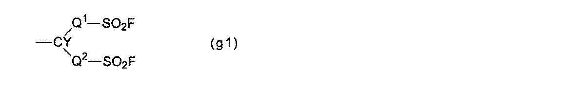
Q2は、単結合、またはエーテル結合性酸素原子を有してもよいペルフルオロアルキレン基である。 Q 1 is a perfluoroalkylene group which may have an etheric oxygen atom.
Q 2 is a perfluoroalkylene group which may have a single bond or an ether bond oxygen atom.
ペルフルオロアルキレン基は、直鎖状であってもよく、分岐状であってもよく、直鎖状であることが好ましい。
ペルフルオロアルキレン基の炭素数は、1~6が好ましく、1~4がより好ましい。炭素数が6以下であれば、原料のモノマー(a)の沸点が低くなり、蒸留精製が容易となる。また、炭素数が6以下であれば、ポリマー(H)のイオン交換容量の低下が抑えられ、プロトン伝導性の低下が抑えられる。 When the perfluoroalkylene group of Q 1 and Q 2 has an etheric oxygen atom, the oxygen atom may be one or two or more. The oxygen atom may be inserted between the carbon atom-carbon atom bonds of the perfluoroalkylene group or may be inserted at the carbon atom bond terminal.
The perfluoroalkylene group may be linear or branched, and is preferably linear.
The perfluoroalkylene group preferably has 1 to 6 carbon atoms, and more preferably 1 to 4 carbon atoms. If the number of carbon atoms is 6 or less, the boiling point of the raw material monomer (a) becomes low, and distillation purification becomes easy. Moreover, if carbon number is 6 or less, the fall of the ion exchange capacity of a polymer (H) will be suppressed, and the fall of proton conductivity will be suppressed.
Q1、Q2の少なくとも一方は、エーテル性の酸素原子を有する炭素数1~6のペルフルオロアルキレン基であることが好ましい。エーテル性の酸素原子を有する炭素数1~6のペルフルオロアルキレン基を有するモノマー(a)は、フッ素ガスによるフッ素化反応を経ずに合成できるため、収率が良好で、製造が容易である。 Q 2 is preferably a C 1-6 perfluoroalkylene group which may have an etheric oxygen atom. When Q 2 is a perfluoroalkylene group having 1 to 6 carbon atoms which may have an etheric oxygen atom, the solid polymer fuel cell is operated for a longer period of time than when Q 2 is a single bond. In addition, it has excellent power generation characteristics.
At least one of Q 1 and Q 2 is preferably a C 1-6 perfluoroalkylene group having an etheric oxygen atom. Since the monomer (a) having a C 1-6 perfluoroalkylene group having an etheric oxygen atom can be synthesized without undergoing a fluorination reaction with a fluorine gas, the yield is good and the production is easy.

構成単位(B)は、構成単位(u2)である。 Structural unit (B):
The structural unit (B) is the structural unit (u2).
R13およびR14は、それぞれ独立にフッ素原子、炭素数1~5のペルフルオロアルキル基、または炭素数1~5のペルフルオロアルコキシ基である。R13およびR14は、後述するモノマー(m2)の重合反応性が高い点から、少なくとも一方がフッ素原子であることが好ましく、両方がフッ素原子であることがより好ましい。
ペルフルオロアルキル基およびペルフルオロアルコキシ基は、直鎖状であってもよく、分岐状であってもよく、直鎖状であることが好ましい。 R 11 and R 12 are each independently a fluorine atom or a perfluoroalkyl group having 1 to 5 carbon atoms.
R 13 and R 14 are each independently a fluorine atom, a C 1-5 perfluoroalkyl group, or a C 1-5 perfluoroalkoxy group. At least one of R 13 and R 14 is preferably a fluorine atom, and more preferably both are fluorine atoms, from the viewpoint of high polymerization reactivity of the monomer (m2) described later.
The perfluoroalkyl group and the perfluoroalkoxy group may be linear or branched, and preferably linear.
他の構成単位(D)は、後述する他のモノマー(d)に基づく構成単位である。 The structural unit (C) is a structural unit based on tetrafluoroethylene.
The other structural unit (D) is a structural unit based on another monomer (d) described later.
ポリマー(F)のTQ値は、250~330℃が好ましく、255~300℃がより好ましく、260~290℃がさらに好ましい。ポリマー(F)のTQ値が前記下限値以上であれば、ポリマー(H)が充分な分子量を有し、機械的強度にも優れる。ポリマー(F)のTQ値が前記上限値以下であれば、ポリマー(H)の溶解性または分散性がよくなり、後述する液状組成物を調製しやすい。
TQ値は、ポリマーの分子量の指標であり、長さ1mm、内径1mmのノズルを用い、2.94MPaの押出し圧力の条件でポリマー(F)の溶融押出しを行った際の押出し量が100mm3/秒となる温度である。 TQ value of polymer (F):
The TQ value of the polymer (F) is preferably 250 to 330 ° C, more preferably 255 to 300 ° C, and further preferably 260 to 290 ° C. When the TQ value of the polymer (F) is at least the lower limit, the polymer (H) has a sufficient molecular weight and is excellent in mechanical strength. When the TQ value of the polymer (F) is not more than the above upper limit value, the solubility or dispersibility of the polymer (H) is improved, and a liquid composition described later can be easily prepared.
The TQ value is an index of the molecular weight of the polymer. The extrusion amount when the polymer (F) is melt-extruded under the condition of the extrusion pressure of 2.94 MPa using a nozzle having a length of 1 mm and an inner diameter of 1 mm is 100 mm 3 / This is the temperature in seconds.
ポリマー(F)は、特定のモノマー(a)、特定のモノマー(b)、特定のモノマー(c)、および必要に応じて他のモノマー(d)を重合することによって製造される。 (Production of polymer (F))
The polymer (F) is produced by polymerizing a specific monomer (a), a specific monomer (b), a specific monomer (c), and, if necessary, another monomer (d).
モノマー(a)は、基(g1)を有するペルフルオロモノマーである。
モノマー(a)としては、膜電極接合体が低温、高湿条件下でも、高温、低湿条件下でもより優れた発電特性を発現できる点から、モノマー(m1)が好ましい。 Monomer (a):
The monomer (a) is a perfluoromonomer having a group (g1).
As the monomer (a), the monomer (m1) is preferable because the membrane / electrode assembly can exhibit better power generation characteristics even under low temperature and high humidity conditions, and also under high temperature and low humidity conditions.

モノマー(m1)としては、ポリマー(H)の製造が容易であり、工業的実施が容易である点から、モノマー(m1-1)~(m1-3)が好ましく、モノマー(m1-1)が特に好ましい。 Q 1 , Q 2 , Y, and q are as described in the structural unit (u1).
As the monomer (m1), the monomers (m1-1) to (m1-3) are preferable because the production of the polymer (H) is easy and the industrial implementation is easy, and the monomer (m1-1) is preferably Particularly preferred.
モノマー(m2)としては、たとえば、モノマー(m2-1)~(m2-8)が挙げられ、膜電極接合体が低温、高湿条件下でも、高温、低湿条件下でもより優れた発電特性を発現できる点から、モノマー(m2-1)が特に好ましい。 R 11 to R 14 are as described for the structural unit (u2).
Examples of the monomer (m2) include monomers (m2-1) to (m2-8), and the membrane / electrode assembly has superior power generation characteristics even under low temperature and high humidity conditions, and even under high temperature and low humidity conditions. From the viewpoint of expression, the monomer (m2-1) is particularly preferable.
他のモノマー(d)としては、クロロトリフルオロエチレン、トリフルオロエチレン、フッ化ビニリデン、フッ化ビニル、エチレン、プロピレン、ペルフルオロ(3-ブテニルビニルエーテル)、ペルフルオロ(アリルビニルエーテル)、ペルフルオロα-オレフィン類(ヘキサフルオロプロピレン等)、(ペルフルオロアルキル)エチレン類((ペルフルオロブチル)エチレン等)、(ペルフルオロアルキル)プロペン類(3-ペルフルオロオクチル-1-プロペン等)、ペルフルオロ(アルキルビニルエーテル)類、下記のモノマー(m3)、特許文献1に記載された5員環を有するペルフルオロモノマー(ただし、モノマー(m2)を除く。)、特許文献1に記載された環化重合により5員環を形成し得るペルフルオロモノマー等が挙げられる。 The other monomer (d) is a monomer other than the monomer (a), the monomer (b), and the monomer (c).
Other monomers (d) include chlorotrifluoroethylene, trifluoroethylene, vinylidene fluoride, vinyl fluoride, ethylene, propylene, perfluoro (3-butenyl vinyl ether), perfluoro (allyl vinyl ether), perfluoro α-olefins (Hexafluoropropylene, etc.), (perfluoroalkyl) ethylenes ((perfluorobutyl) ethylene, etc.), (perfluoroalkyl) propenes (3-perfluorooctyl-1-propene, etc.), perfluoro (alkyl vinyl ethers), the following monomers (M3), a perfluoromonomer having a 5-membered ring described in Patent Document 1 (excluding the monomer (m2)), and a perfluoromonomer capable of forming a 5-membered ring by cyclopolymerization described in Patent Document 1 Etc. It is.

重合法としては、バルク重合法、溶液重合法、懸濁重合法、乳化重合法等の公知の重合法が挙げられる。また、液体または超臨界の二酸化炭素中にて重合を行ってもよい。
重合は、ラジカルが生起する条件で行われる。ラジカルを生起させる方法としては、紫外線、γ線、電子線等の放射線を照射する方法、ラジカル開始剤を添加する方法等が挙げられる。重合温度は、通常、10~150℃である。 Monomer polymerization:
Examples of the polymerization method include known polymerization methods such as a bulk polymerization method, a solution polymerization method, a suspension polymerization method, and an emulsion polymerization method. Moreover, you may superpose | polymerize in a liquid or supercritical carbon dioxide.
Polymerization is performed under conditions where radicals occur. Examples of the method for generating radicals include a method of irradiating radiation such as ultraviolet rays, γ rays, and electron beams, a method of adding a radical initiator, and the like. The polymerization temperature is usually 10 to 150 ° C.
非イオン性のラジカル開始剤としては、ビス(フルオロアシル)ペルオキシド類、ビス(クロロフルオロアシル)ペルオキシド類、ジアルキルペルオキシジカーボネート類、ジアシルペルオキシド類、ペルオキシエステル類、ジアルキルペルオキシド類、ビス(フルオロアルキル)ペルオキシド類、アゾ化合物類等が挙げられる。
分散媒には、助剤として前記溶媒;懸濁粒子の凝集を防ぐ分散安定剤として界面活性剤;分子量調整剤として炭化水素系化合物(ヘキサン、メタノール等)等を添加してもよい。 In the suspension polymerization method, water is used as a dispersion medium, a monomer, a nonionic radical initiator or the like is added to the dispersion medium, and radicals are generated in the dispersion medium to polymerize the monomer.
Nonionic radical initiators include bis (fluoroacyl) peroxides, bis (chlorofluoroacyl) peroxides, dialkyl peroxydicarbonates, diacyl peroxides, peroxyesters, dialkyl peroxides, bis (fluoroalkyl) Examples thereof include peroxides and azo compounds.
The dispersion medium may contain the above-mentioned solvent as an auxiliary agent; a surfactant as a dispersion stabilizer that prevents aggregation of suspended particles; and a hydrocarbon compound (hexane, methanol, etc.) as a molecular weight regulator.
ポリマー(H)は、ポリマー(F)の前駆体基をイオン交換基に変換したポリマーであり、特定の構成単位(A’)と、特定の構成単位(B)と、特定の構成単位(C)と、必要に応じて他の構成単位(D)とを有するポリマーである。 (Polymer (H))
The polymer (H) is a polymer obtained by converting a precursor group of the polymer (F) into an ion exchange group, and includes a specific structural unit (A ′), a specific structural unit (B), and a specific structural unit (C ) And, if necessary, another structural unit (D).
構成単位(A’)は、構成単位(A)の前駆体基をイオン交換基に変換した構成単位である。イオン交換基は、基(g’1)であることが好ましい。 Structural unit (A ′):
The structural unit (A ′) is a structural unit obtained by converting the precursor group of the structural unit (A) into an ion exchange group. The ion exchange group is preferably a group (g′1).

Rfは、エーテル結合性酸素原子を有してもよい直鎖または分岐のペルフルオロアルキル基である。ペルフルオロアルキル基の炭素数は、1~8が好ましく、1~6がより好ましい。基(g’1)が2個以上のRfを有する場合、Rfは、それぞれ同じ基であってもよく、それぞれ異なる基であってもよい。 Q 1 , Q 2 and Y are as described for the group (g1).
R f is a linear or branched perfluoroalkyl group which may have an etheric oxygen atom. The perfluoroalkyl group preferably has 1 to 8 carbon atoms, and more preferably 1 to 6 carbon atoms. When group (g′1) has two or more R f s , R f may be the same group or different groups.
基(g’1)における-SO2X(SO2Rf)a -H+としては、スルホン酸基(-SO3 -H+基)、スルホンイミド基(-SO2N(SO2Rf)-H+基)、またはスルホンメチド基(-SO2C(SO2Rf)2)-H+基)が挙げられる。 X is an oxygen atom, a nitrogen atom or a carbon atom, a = 0 when X is an oxygen atom, a = 1 when X is a nitrogen atom, and a = 2 when X is a carbon atom. .
-SO 2 X (SO 2 R f ) a in group (g'1) - H + as the sulfonic acid group (-SO 3 - H + group), a sulfonimide group (-SO 2 N (SO 2 R f ) - H + group), or a sulfonmethide group (-SO 2 C (SO 2 R f) 2) - H + group).

構成単位(u’1)としては、ポリマー(H)の製造が容易であり、工業的実施が容易である点から、構成単位(u’1-1)~(u’1-3)が好ましく、構成単位(u’1-1)が特に好ましい。 Q 1 , Q 2 , Y, and q are as described in the structural unit (u1). R f , X, and a are as described for the group (g′1).
As the structural unit (u′1), the structural units (u′1-1) to (u′1-3) are preferable from the viewpoint of easy production of the polymer (H) and easy industrial implementation. The structural unit (u′1-1) is particularly preferable.
構成単位(C)は、ポリマー(F)において説明した通りである。
他の構成単位(D)は、ポリマー(F)において説明した通りである。ただし、ポリマー(F)がモノマー(m3)に基づく構成単位を有する場合、該構成単位の前駆体基は、ポリマー(H)を製造する際にイオン交換基に変換される。 The structural unit (B) is as described in the polymer (F).
The structural unit (C) is as described in the polymer (F).
The other structural unit (D) is as described in the polymer (F). However, when the polymer (F) has a structural unit based on the monomer (m3), the precursor group of the structural unit is converted into an ion exchange group when the polymer (H) is produced.
ポリマー(H)のイオン交換容量は、0.7~1.29ミリ当量/g乾燥樹脂が好ましく、0.93~1.23ミリ当量/g乾燥樹脂がより好ましく、1.03~1.23ミリ当量/g乾燥樹脂がさらに好ましい。イオン交換容量が前記下限値以上であれば、ポリマー(H)の導電性が高くなるため、固体高分子形燃料電池の触媒層の電解質材料として用いた場合、充分な出力電圧を得ることできる。イオン交換容量が前記上限値以下であれば、触媒層におけるフラッディング現象がさらに抑えられ、膜電極接合体が低温、高湿条件下でもさらに優れた発電特性を発現できる。 Ion exchange capacity:
The ion exchange capacity of the polymer (H) is preferably 0.7 to 1.29 meq / g dry resin, more preferably 0.93 to 1.23 meq / g dry resin, and 1.03 to 1.23. More preferred are milliequivalents / g dry resin. When the ion exchange capacity is equal to or higher than the lower limit, the conductivity of the polymer (H) is increased. Therefore, when the ion exchange capacity is used as the electrolyte material of the catalyst layer of the polymer electrolyte fuel cell, a sufficient output voltage can be obtained. When the ion exchange capacity is not more than the above upper limit value, the flooding phenomenon in the catalyst layer is further suppressed, and the membrane electrode assembly can exhibit further excellent power generation characteristics even under low temperature and high humidity conditions.
ポリマー(H)は、ポリマー(F)の前駆体基をイオン交換基に変換することによって製造される。 (Production of polymer (H))
The polymer (H) is produced by converting the precursor group of the polymer (F) into an ion exchange group.
(i)ポリマー(F)の-SO2F基を加水分解してスルホン酸塩とし、スルホン酸塩を酸型化してスルホン酸基に変換する方法。
(ii)ポリマー(F)の-SO2F基をイミド化して塩型のスルホンイミド基とし、さらに酸型化して酸型のスルホンイミド基に変換する方法。 -SO 2 F groups sulfonic acid groups - as a way to convert (-SO 3 H + group), include the following methods (i), a -SO 2 F group sulfonimide group (-SO 2 N ( As a method for converting into (SO 2 R f ) − H + group), the following method (ii) may be mentioned.
(I) A method in which the —SO 2 F group of the polymer (F) is hydrolyzed to form a sulfonate, and the sulfonate is converted into an acid form and converted into a sulfonate group.
(Ii) A method in which the —SO 2 F group of the polymer (F) is imidized to form a salt type sulfonimide group, and further converted to an acid type to convert to an acid type sulfonimide group.
加水分解は、たとえば、溶媒中にてポリマー(F)と塩基性化合物とを接触させて行う。塩基性化合物としては、水酸化ナトリウム、水酸化カリウム等が挙げられる。溶媒としては、水、水と極性溶媒との混合溶媒等が挙げられる。極性溶媒としては、アルコール類(メタノール、エタノール等)、ジメチルスルホキシド等が挙げられる。
酸型化は、たとえば、スルホン酸塩を有するポリマーを、塩酸、硫酸等の水溶液に接触させて行う。加水分解および酸型化は、通常、0~120℃にて行う。 Method (i):
Hydrolysis is performed, for example, by contacting the polymer (F) with a basic compound in a solvent. Examples of the basic compound include sodium hydroxide and potassium hydroxide. Examples of the solvent include water, a mixed solvent of water and a polar solvent, and the like. Examples of the polar solvent include alcohols (methanol, ethanol, etc.), dimethyl sulfoxide and the like.
The acidification is performed, for example, by bringing a polymer having a sulfonate into contact with an aqueous solution such as hydrochloric acid or sulfuric acid. Hydrolysis and acidification are usually performed at 0 to 120 ° C.
イミド化としては、下記の方法が挙げられる。
(ii-1)-SO2F基と、RfSO2NHMとを反応させる方法。
(ii-2)アルカリ金属水酸化物、アルカリ金属炭酸塩、MF、アンモニアまたは1~3級アミンの存在下で、-SO2F基と、RfSO2NH2とを反応させる方法。
(ii-3)-SO2F基と、RfSO2NMSi(CH3)3とを反応させる方法。
ただし、Mは、アルカリ金属または1~4級のアンモニウムである。
酸型化は、塩型のスルホンイミド基を有するポリマーを、酸(硫酸、硝酸、塩酸等)で処理することにより行う。 Method (ii):
Examples of imidization include the following methods.
(Ii-1) A method of reacting —SO 2 F group with R f SO 2 NHM.
(Ii-2) A method of reacting —SO 2 F group with R f SO 2 NH 2 in the presence of alkali metal hydroxide, alkali metal carbonate, MF, ammonia or primary to tertiary amine.
(Ii-3) A method of reacting a —SO 2 F group with R f SO 2 NMSi (CH 3 ) 3 .
M is an alkali metal or primary to quaternary ammonium.
Acidification is carried out by treating a polymer having a salt-type sulfonimide group with an acid (sulfuric acid, nitric acid, hydrochloric acid, etc.).
本発明の液状組成物は、分散媒と、該分散媒に分散された本発明の電解質材料とを含む組成物である。 <Liquid composition>
The liquid composition of the present invention is a composition comprising a dispersion medium and the electrolyte material of the present invention dispersed in the dispersion medium.
水酸基を有する有機溶媒としては、メタノール、エタノール、1-プロパノール、2-プロパノール、2,2,2-トリフルオロエタノール、2,2,3,3,3-ペンタフルオロ-1-プロパノール、2,2,3,3-テトラフルオロ-1-プロパノール、4,4,5,5,5-ペンタフルオロ-1-ペンタノール、1,1,1,3,3,3-ヘキサフルオロ-2-プロパノール、3,3,3-トリフルオロ-1-プロパノール、3,3,4,4,5,5,6,6,6-ノナフルオロ-1-ヘキサノール、3,3,4,4,5,5,6,6,7,7,8,8,8-トリデカフルオロ-1-オクタノール等が挙げられる。
水酸基を有する有機溶媒は、1種を単独で用いてもよく、2種以上を混合して用いてもよい。 The dispersion medium contains an organic solvent having a hydroxyl group.
Examples of the organic solvent having a hydroxyl group include methanol, ethanol, 1-propanol, 2-propanol, 2,2,2-trifluoroethanol, 2,2,3,3,3-pentafluoro-1-propanol, 2,2 , 3,3-tetrafluoro-1-propanol, 4,4,5,5,5-pentafluoro-1-pentanol, 1,1,1,3,3,3-hexafluoro-2-propanol, 3, , 3,3-trifluoro-1-propanol, 3,3,4,4,5,5,6,6,6-nonafluoro-1-hexanol, 3,3,4,4,5,5,6 6,7,7,8,8,8-tridecafluoro-1-octanol and the like.
The organic solvent which has a hydroxyl group may be used individually by 1 type, and 2 or more types may be mixed and used for it.
水の割合は、分散媒(100質量%)のうち、10~99質量%が好ましく、40~99質量%がより好ましい。水の割合を増やすことにより、分散媒に対する電解質材料の分散性を向上できる。
水酸基を有する有機溶媒の割合は、分散媒(100質量%)のうち、1~90質量%が好ましく、1~60質量%がより好ましい。
電解質材料の割合は、液状組成物(100質量%)のうち、1~50質量%が好ましく、3~30質量%がより好ましい。 The dispersion medium preferably contains water.
The proportion of water is preferably 10 to 99% by mass and more preferably 40 to 99% by mass in the dispersion medium (100% by mass). By increasing the proportion of water, the dispersibility of the electrolyte material in the dispersion medium can be improved.
The proportion of the organic solvent having a hydroxyl group is preferably 1 to 90% by mass and more preferably 1 to 60% by mass in the dispersion medium (100% by mass).
The ratio of the electrolyte material is preferably 1 to 50% by mass and more preferably 3 to 30% by mass in the liquid composition (100% by mass).
具体的な液状組成物の調製方法としては、大気圧下、またはオートクレーブ等で密閉した状態下において、分散媒中の電解質材料に撹拌等のせん断を加える方法が挙げられる。
調製温度は、0~250℃が好ましく、20~150℃がより好ましい。必要に応じて、超音波等のせん断を付与してもよい。 Regarding the method for preparing the liquid composition, for example, Japanese Patent Publication No. 4-35226, Japanese Patent Publication No. 2001-504872, Japanese Patent Application Laid-Open No. 2005-82749, International Publication No. 2006/38928, Japanese Patent Application Laid-Open No. 2004-519296. It can be prepared based on the preparation method described in the above.
As a specific method for preparing the liquid composition, there is a method in which shearing such as stirring is applied to the electrolyte material in the dispersion medium under atmospheric pressure or in a state sealed with an autoclave or the like.
The preparation temperature is preferably 0 to 250 ° C, more preferably 20 to 150 ° C. You may provide shearing, such as an ultrasonic wave, as needed.
本発明の液状組成物は後述の膜電極接合体における触媒層の形成に好適に用いられる。 In addition, when a liquid mixture in which an electrolyte material, an organic solvent and water are mixed is subjected to shearing such as stirring to obtain a liquid composition, the liquid mixture in which the organic solvent and water are added all at once to the electrolyte material is stirred. Shear may be applied, or an organic solvent or water may be mixed into the electrolyte material in a plurality of times, and shearing such as stirring may be applied between them. For example, a shearing solution such as stirring is added to a mixed solution obtained by adding a part of an organic solvent and a part of water to the electrolyte material, and then the remaining organic solvent or water is added to the mixed solution and then shearing such as stirring is performed again. You may make it add. Alternatively, only an organic solvent may be added to the electrolyte material and shearing such as stirring may be performed, and then only water may be added and shearing such as stirring may be applied again.
The liquid composition of the present invention is suitably used for forming a catalyst layer in a membrane electrode assembly described later.
図1は、本発明の固体高分子形燃料電池用膜電極接合体(以下、膜電極接合体と記す。)の一例の模式断面図である。膜電極接合体10は、触媒層11およびガス拡散層12を有するアノード13と、触媒層11およびガス拡散層12を有するカソード14と、アノード13とカソード14との間に、触媒層11に接した状態で配置される固体高分子電解質膜15とを具備する。 <Membrane electrode assembly>
FIG. 1 is a schematic cross-sectional view of an example of a membrane electrode assembly for a polymer electrolyte fuel cell of the present invention (hereinafter referred to as a membrane electrode assembly). The
触媒層11は、触媒と、プロトン伝導性ポリマーとを含む層である。
触媒としては、カーボン担体に白金または白金合金を担持した担持触媒が挙げられる。カーボン担体としては、カーボンブラック粉末が挙げられる。 (Catalyst layer)
The
Examples of the catalyst include a supported catalyst in which platinum or a platinum alloy is supported on a carbon support. Examples of the carbon carrier include carbon black powder.
(i)触媒層形成用液を、固体高分子電解質膜15、ガス拡散層12、またはカーボン層16上に塗布し、乾燥させる方法。
(ii)触媒層形成用液を基材フィルム上に塗布し、乾燥させ触媒層11を形成し、該触媒層11を固体高分子電解質膜15上に転写する方法。 Examples of the method for forming the
(I) A method of applying the catalyst layer forming liquid on the solid
(Ii) A method in which a catalyst layer forming solution is applied on a base film, dried to form a
ガス拡散層12は、触媒層11に均一にガスを拡散させる機能および集電体としての機能を有する。ガス拡散層12としては、カーボンペーパー、カーボンクロス、カーボンフェルト等が挙げられる。ガス拡散層12は、ポリテトラフルオロエチレン等によって撥水化処理されていることが好ましい。 (Gas diffusion layer)
The
膜電極接合体10は、図2に示すように、触媒層11とガス拡散層12との間にカーボン層16を有してもよい。カーボン層16を配置することにより、触媒層11の表面のガス拡散性が向上し、膜電極接合体10の発電特性が大きく向上する。 (Carbon layer)
The
カーボンとしては、繊維径1~1000nm、繊維長1000μm以下のカーボンナノファイバーが好ましい。
非イオン性含フッ素ポリマーとしては、ポリテトラフルオロエチレン等が挙げられる。 The carbon layer 16 is a layer containing carbon and a nonionic fluorine-containing polymer.
As carbon, carbon nanofibers having a fiber diameter of 1 to 1000 nm and a fiber length of 1000 μm or less are preferable.
Examples of the nonionic fluorine-containing polymer include polytetrafluoroethylene.
固体高分子電解質膜15は、プロトン伝導性ポリマーを含む膜である。
プロトン伝導性ポリマーとしては、本発明の電解質材料、または公知の電解質材料が挙げられる。公知の電解質材料としては、モノマー(m3)に基づく構成単位とTFEに基づく構成単位とを有するポリマーの-SO2F基をスルホン酸基に変換したポリマー;モノマー(m1)に基づく構成単位とTFEに基づく構成単位とを有するポリマーの-SO2F基をスルホン酸基に変換したポリマー等が挙げられる。 (Solid polymer electrolyte membrane)
The solid
Examples of the proton conductive polymer include the electrolyte material of the present invention or a known electrolyte material. Known electrolyte materials include a polymer having a structural unit based on the monomer (m3) and a structural unit based on TFE, a polymer obtained by converting —SO 2 F groups into sulfonic acid groups; a structural unit based on the monomer (m1) and TFE And a polymer obtained by converting —SO 2 F group of a polymer having a structural unit based on the above to a sulfonic acid group.
液状組成物は、水酸基を有する有機溶媒および水を含む分散媒に、電解質材料を分散させた分散液である。 The solid
The liquid composition is a dispersion in which an electrolyte material is dispersed in a dispersion medium containing an organic solvent having a hydroxyl group and water.
固体高分子電解質膜15は、必要に応じて過酸化水素水で処理してもよい。 In order to stabilize the solid
The solid
固体高分子電解質膜15は、乾燥を防ぐための保水剤として、シリカ、またはヘテロポリ酸(リン酸ジルコニウム、リンモリブデン酸、リンタングステン酸等)を含んでいてもよい。 The solid
The solid
膜電極接合体10は、たとえば、下記の方法にて製造される。
(i)固体高分子電解質膜15上に触媒層11を形成して膜触媒層接合体とし、該膜触媒層接合体をガス拡散層12で挟み込む方法。
(ii)ガス拡散層12上に触媒層11を形成して電極(アノード13、カソード14)とし、固体高分子電解質膜15を該電極で挟み込む方法。 (Method for producing membrane electrode assembly)
The
(I) A method in which the
(Ii) A method in which the
本発明の膜電極接合体は、固体高分子形燃料電池に用いられる。固体高分子形燃料電池は、たとえば、2枚のセパレータの間に膜電極接合体を挟んでセルを形成し、複数のセルをスタックすることにより製造される。 <Solid polymer fuel cell>
The membrane electrode assembly of the present invention is used for a polymer electrolyte fuel cell. A polymer electrolyte fuel cell is manufactured, for example, by forming a cell by sandwiching a membrane electrode assembly between two separators and stacking a plurality of cells.
固体高分子形燃料電池の種類としては、水素/酸素型燃料電池、直接メタノール型燃料電池(DMFC)等が挙げられる。DMFCの燃料に用いるメタノールまたはメタノール水溶液は、液フィードであってもよく、ガスフィードであってもよい。 Examples of the separator include a conductive carbon plate in which a groove serving as a passage for an oxidant gas (air, oxygen, etc.) containing fuel gas or oxygen is formed.
Examples of the polymer electrolyte fuel cell include a hydrogen / oxygen fuel cell and a direct methanol fuel cell (DMFC). The methanol or methanol aqueous solution used for the DMFC fuel may be a liquid feed or a gas feed.
ポリマー(F)における各構成単位の割合については、ポリマー(F)についての19F-NMRの測定結果から求めた。 (Percentage of each structural unit)
The proportion of each structural unit in the polymer (F) was determined from the 19 F-NMR measurement results for the polymer (F).
長さ1mm、内径1mmのノズルを備えたフローテスタCFT-500A(島津製作所製)を用い、2.94MPaの押出し圧力の条件で温度を変えてポリマー(F)の押出し量を測定し、押出し量が100mm3/秒となる温度(TQ値)を求めた。 (TQ value)
Using a flow tester CFT-500A (manufactured by Shimadzu Corp.) equipped with a nozzle with a length of 1 mm and an inner diameter of 1 mm, the extrusion amount of the polymer (F) was measured by changing the temperature under the extrusion pressure of 2.94 MPa. Was determined to be a temperature (TQ value) at which 100 mm 3 / sec.
ポリマー(H)をグローブボックス中に入れ、乾燥窒素を流した雰囲気中に室温で24時間放置し、乾燥させた。グローブボックス中でポリマー(H)の乾燥質量を測定した。
ポリマー(H)を2モル/Lの塩化ナトリウム水溶液に浸漬し、60℃で1時間放置した後、室温まで冷却した。ポリマー(H)を浸漬していた塩化ナトリウム水溶液を、0.5モル/Lの水酸化ナトリウム水溶液で滴定することにより、ポリマー(H)のイオン交換容量を求めた。 (Ion exchange capacity)
The polymer (H) was placed in a glove box and left to dry in an atmosphere of flowing dry nitrogen at room temperature for 24 hours. The dry mass of the polymer (H) was measured in the glove box.
The polymer (H) was immersed in a 2 mol / L sodium chloride aqueous solution, allowed to stand at 60 ° C. for 1 hour, and then cooled to room temperature. The aqueous sodium chloride solution in which the polymer (H) was immersed was titrated with a 0.5 mol / L aqueous sodium hydroxide solution to determine the ion exchange capacity of the polymer (H).
膜電極接合体の温度を60℃に維持し、アノードに水素(利用率50%)、カソードに空気(利用率50%)を、それぞれ175kPa(絶対圧力)に加圧して供給した。水素および空気ともに相対湿度100%RHで供給し、電流密度が1.5A/cm2のときのセル電圧を記録し、下記基準にて評価した。
○(優):セル電圧が0.5V以上。
△(良):セル電圧が0.4V以上0.5V未満。
×(不良):セル電圧が0.4V未満。 (Power generation characteristics 1)
The temperature of the membrane electrode assembly was maintained at 60 ° C., and hydrogen (utilization rate 50%) was supplied to the anode and air (utilization rate 50%) was pressurized to 175 kPa (absolute pressure) and supplied. Both hydrogen and air were supplied at a relative humidity of 100% RH, and the cell voltage when the current density was 1.5 A / cm 2 was recorded and evaluated according to the following criteria.
○ (excellent): Cell voltage is 0.5 V or more.
Δ (good): Cell voltage is 0.4 V or more and less than 0.5 V.
X (defect): Cell voltage is less than 0.4V.
膜電極接合体の温度を80℃に維持し、アノードに水素(利用率50%)、カソードに空気(利用率50%)を、それぞれ175kPa(絶対圧力)に加圧して供給した。水素および空気ともに加湿をせずに供給し、電流密度が1.0A/cm2のときのセル電圧を記録し、下記基準にて評価した。
○(優):セル電圧が0.6V以上。
△(良):セル電圧が0.5V以上 0.6V未満。
×(不良):セル電圧が0.5V未満。 (Power generation characteristics 2)
The temperature of the membrane / electrode assembly was maintained at 80 ° C., and hydrogen (utilization rate 50%) was supplied to the anode and air (utilization rate 50%) was pressurized to 175 kPa (absolute pressure) and supplied. Both hydrogen and air were supplied without humidification, and the cell voltage when the current density was 1.0 A / cm 2 was recorded and evaluated according to the following criteria.
○ (excellent): Cell voltage is 0.6 V or more.
Δ (good): The cell voltage is 0.5 V or more and less than 0.6 V.
X (defect): Cell voltage is less than 0.5V.
BSVE-2E:モノマー(m1-1)、 PDD:モノマー(m2-1)、
TFE:テトラフルオロエチレン、 PSVE:モノマー(m3-1)、
MMD:モノマー(m4-1)。 (Abbreviation)
BSVE-2E: monomer (m1-1), PDD: monomer (m2-1),
TFE: tetrafluoroethylene, PSVE: monomer (m3-1),
MMD: monomer (m4-1).
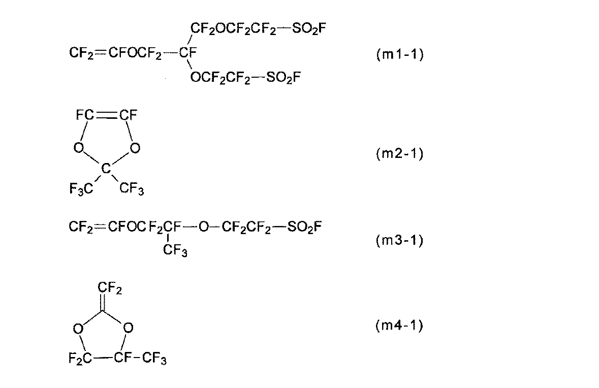
C6H:C6F13H、 225cb:CClF2CF2CHClF。 PFB: (C 3 F 7 COO ) 2, IPP: ((CH 3) 2 CHOCOO) 2,
C6H: C 6 F 13 H, 225cb: CClF 2 CF 2 CHClF.
内容積2575mLのステンレス製オートクレーブに、氷水で冷却しながら減圧下でBSVE-2Eの1076gを仕込み脱気した。PDDの328gを仕込んだ。24℃に昇温した後、窒素ガスを0.1MPa導入した。圧力が変化しないことを確認した後、TFEの54.0gを仕込んだ。C6Hに溶解したPFBの3.1質量%溶液の13.64gを窒素ガスで加圧添加した後、C6Hの4gで添加ラインを洗浄した。重合開始から24時間後、オートクレーブを冷却して重合反応を停止し、系内のガスをパージしてポリマー(F-1)の溶液を得た。 (Example 1)
A stainless steel autoclave with an internal volume of 2575 mL was charged with 1076 g of BSVE-2E under reduced pressure while being cooled with ice water, and deaerated. 328 g of PDD was charged. After raising the temperature to 24 ° C., 0.1 MPa of nitrogen gas was introduced. After confirming that the pressure did not change, 54.0 g of TFE was charged. After adding 13.64 g of a 3.1 mass% solution of PFB dissolved in C6H with nitrogen gas, the addition line was washed with 4 g of C6H. 24 hours after the start of the polymerization, the autoclave was cooled to stop the polymerization reaction, and the gas in the system was purged to obtain a polymer (F-1) solution.
内容積230mLのステンレス製オートクレーブに、BSVE-2Eの94.26g、PDDの35.48gを仕込んで、液体窒素で十分に凍結脱気を行った。TFEの3.90gを仕込み、28℃に昇温した。圧力が変化しないことを確認した後、窒素ガスを0.1MPa導入した。C6Hに溶解したPFBの3.1質量%溶液の1.26gを窒素ガスで加圧添加した後、C6Hの2gで添加ラインを洗浄した。重合開始から24時間撹拌した後、オートクレーブを冷却して反応を停止し、系内のガスをパージしてポリマー(F-2)の溶液を得た。 (Example 2)
A stainless steel autoclave having an internal volume of 230 mL was charged with 94.26 g of BSVE-2E and 35.48 g of PDD, and sufficiently freeze-deaerated with liquid nitrogen. 3.90 g of TFE was charged and the temperature was raised to 28 ° C. After confirming that the pressure did not change, 0.1 MPa of nitrogen gas was introduced. After adding 1.26 g of a 3.1 wt% solution of PFB dissolved in C6H with nitrogen gas, the addition line was washed with 2 g of C6H. After stirring for 24 hours from the start of polymerization, the autoclave was cooled to stop the reaction, and the gas in the system was purged to obtain a polymer (F-2) solution.
例1と同様にして、ポリマー(H-2)から液状組成物(L-2)を得た。 In the same manner as in Example 1, polymer (H-2) was obtained from polymer (F-2). Table 2 shows the ion exchange capacity of the polymer (H-2).
In the same manner as in Example 1, a liquid composition (L-2) was obtained from the polymer (H-2).
仕込み量、温度を表1に記載のように変えた以外は、例2と同様にしてポリマー(F-3)、(F-4)、(F-5)を得る。ポリマー(F-3)、(F-4)、(F-5)の収量を表1に示す。ポリマー(F-3)、(F-4)、(F-5)の各構成単位の割合、TQ値を表2に示す。 (Examples 3 to 5)
Polymers (F-3), (F-4), and (F-5) are obtained in the same manner as in Example 2 except that the amount charged and the temperature are changed as shown in Table 1. The yields of the polymers (F-3), (F-4) and (F-5) are shown in Table 1. Table 2 shows the proportions and TQ values of the structural units of the polymers (F-3), (F-4), and (F-5).
例1と同様にして、ポリマー(H-3)、(H-4)、(H-5)から液状組成物(L-3)、(L-4)(L-5)を得る。 In the same manner as in Example 1, the polymers (H-3), (H-4) and (H-5) are obtained from the polymers (F-3), (F-4) and (F-5). Table 2 shows the ion exchange capacities of the polymers (H-3), (H-4), and (H-5).
In the same manner as in Example 1, liquid compositions (L-3), (L-4) and (L-5) are obtained from the polymers (H-3), (H-4) and (H-5).
内容積125mLのステンレス製オートクレーブに、PDDの11.71g、BSVE-2Eの95.15gおよびIPPの33mgを仕込み、液体窒素による冷却下、充分脱気する。TFEの0.6gを仕込み、40℃に昇温して、18時間撹拌する。オートクレーブを冷却して反応を停止し、ポリマー(F-6)の溶液を得る。 (Example 6)
A stainless steel autoclave with an internal volume of 125 mL is charged with 11.71 g of PDD, 95.15 g of BSVE-2E and 33 mg of IPP, and sufficiently deaerated under cooling with liquid nitrogen. Charge 0.6 g of TFE, raise the temperature to 40 ° C., and stir for 18 hours. The reaction is stopped by cooling the autoclave to obtain a solution of polymer (F-6).
例1と同様にして、ポリマー(H-6)から液状組成物(L-6)を得る。 In the same manner as in Example 1, polymer (H-6) is obtained from polymer (F-6). Table 2 shows the ion exchange capacity of the polymer (H-6).
In the same manner as in Example 1, a liquid composition (L-6) is obtained from the polymer (H-6).
内容積125mLのステンレス製オートクレーブに、PDDの24.0g、BSVE-2Eの79.0g、225cbの18g、IPPの54.0mgを仕込み、液体窒素による冷却下、充分脱気する。TFEの5.8gを系内に導入し、40℃に昇温する。40℃で21時間撹拌した後、系内のガスをパージし、オートクレーブを室温に戻し、ポリマー(F-7)の溶液を得る。 (Example 7)
A stainless steel autoclave having an internal volume of 125 mL is charged with 24.0 g of PDD, 79.0 g of BSVE-2E, 18 g of 225 cb, and 54.0 mg of IPP, and sufficiently deaerated under cooling with liquid nitrogen. 5.8 g of TFE is introduced into the system, and the temperature is raised to 40 ° C. After stirring at 40 ° C. for 21 hours, the gas in the system is purged, the autoclave is returned to room temperature, and a solution of polymer (F-7) is obtained.
例1と同様にして、ポリマー(H-7)から液状組成物(L-7)を得る。 In the same manner as in Example 1, polymer (H-7) is obtained from polymer (F-7). Table 2 shows the ion exchange capacity of the polymer (H-7).
In the same manner as in Example 1, a liquid composition (L-7) is obtained from the polymer (H-7).
仕込み量、温度を表1に記載のように変えた以外は、例7と同様にしてポリマー(F-8)を得る。ポリマー(F-8)の収量を表1に示す。ポリマー(F-8)の各構成単位の割合、TQ値を表2に示す。 (Example 8)
A polymer (F-8) is obtained in the same manner as in Example 7 except that the charging amount and temperature are changed as shown in Table 1. The yield of polymer (F-8) is shown in Table 1. Table 2 shows the proportion and TQ value of each structural unit of the polymer (F-8).
仕込み量、温度を表1に記載のように変えた以外は、例7と同様にしてポリマー(F-9)を得る。ポリマー(F-9)の収量を表1に示す。ポリマー(F-9)の各構成単位の割合、TQ値を表2に示す。 (Example 9)
A polymer (F-9) is obtained in the same manner as in Example 7, except that the charging amount and temperature are changed as shown in Table 1. The yield of polymer (F-9) is shown in Table 1. Table 2 shows the proportion and TQ value of each structural unit of the polymer (F-9).
例7と同様にして、液状組成物を得ようとしたが、ポリマー(H-9)が分散媒に分散せず固形として残り、液状組成物が得られない。 In the same manner as in Example 7, the polymer (H-9) is obtained from the polymer (F-9). Table 2 shows the ion exchange capacity of the polymer (H-9).
In the same manner as in Example 7, an attempt was made to obtain a liquid composition, but the polymer (H-9) was not dispersed in the dispersion medium and remained as a solid, and no liquid composition was obtained.
PDDをMMDに変更し、仕込み量および温度を表1に記載のように変えた以外は、例7と同様にしてポリマー(F-10)を得る。ポリマー(F-10)の収量を表1に示す。ポリマー(F-10)の各構成単位の割合、TQ値を表2に示す。 (Example 10)
A polymer (F-10) is obtained in the same manner as in Example 7 except that PDD is changed to MMD and the charging amount and temperature are changed as shown in Table 1. The yield of polymer (F-10) is shown in Table 1. Table 2 shows the proportion and TQ value of each structural unit of the polymer (F-10).
例7と同様にして、ポリマー(H-10)から液状組成物(L-10)を得る。 Analogously to Example 7, polymer (H-10) is obtained from polymer (F-10). Table 2 shows the ion exchange capacity of the polymer (H-10).
In the same manner as in Example 7, the liquid composition (L-10) is obtained from the polymer (H-10).
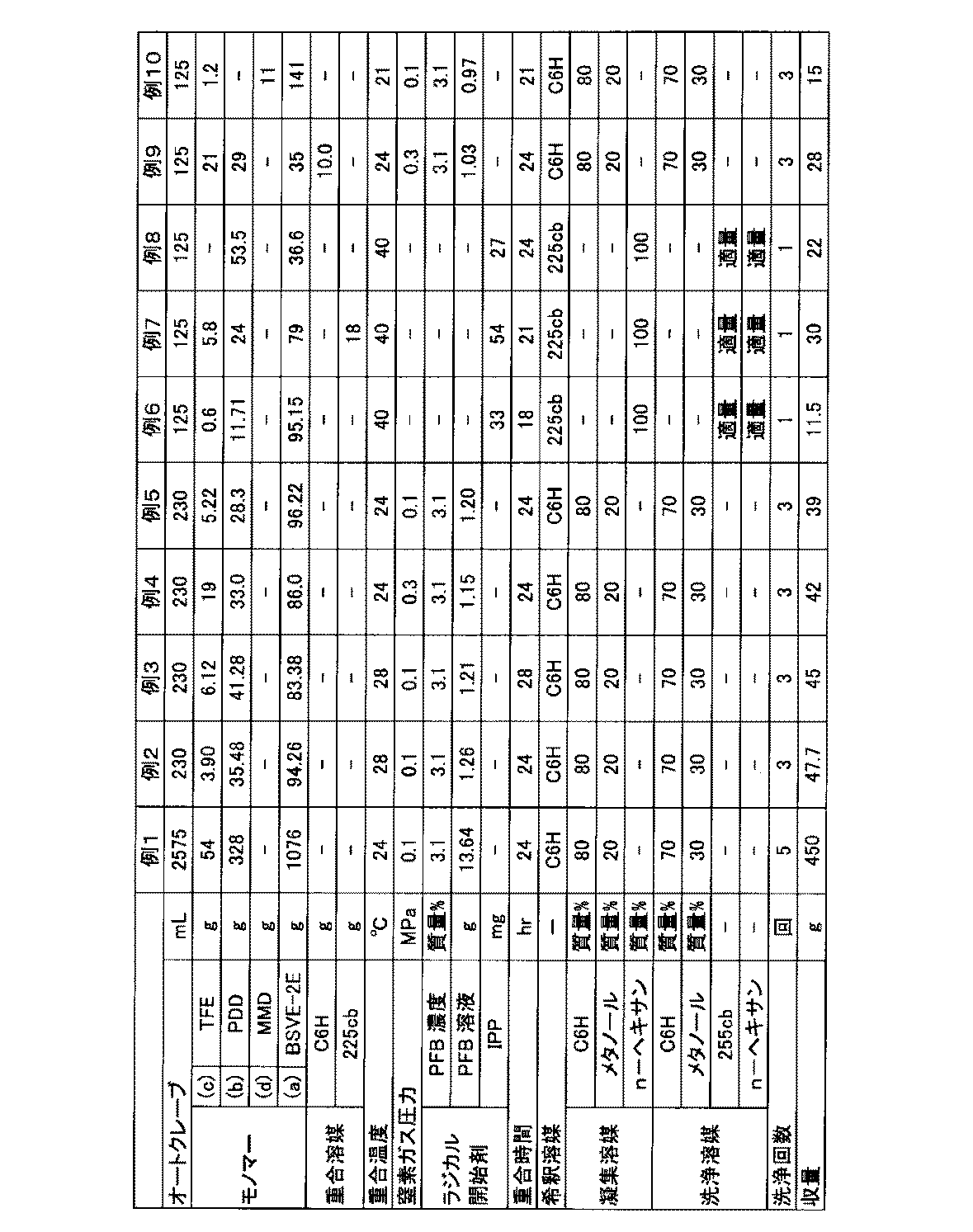
国際公開第2008/090990号の第29頁の例5に記載された方法と同様にBSVE-EとPSVEとTFEとを重合して、ポリマー(F’)を得た。
例1と同様にして、ポリマー(F’)の-SO2F基をスルホン酸基に変換してポリマー(H’)を得た。ポリマー(H’)のイオン交換容量は、1.5ミリ当量/g乾燥樹脂であった。 (Preparation of solid polymer electrolyte membrane)
BSVE-E, PSVE and TFE were polymerized in the same manner as described in Example 5 on page 29 of WO2008 / 090990 to obtain a polymer (F ′).
In the same manner as in Example 1, the —SO 2 F group of the polymer (F ′) was converted to a sulfonic acid group to obtain a polymer (H ′). The ion exchange capacity of the polymer (H ′) was 1.5 meq / g dry resin.
カーボン粉末に白金を50質量%担持した担持触媒の10gに水の39gを加え、10分間超音波を照射し、触媒の分散液を得た。触媒の分散液に、液状組成物(L-1)の60gを加え、さらにエタノールの64gを加えて固形分濃度を8質量%とし、触媒層形成用液を得た。該液を別途用意したETFEシートの表面に塗布し、80℃で30分乾燥し、さらに160℃で30分の熱処理を施し、白金量が0.2mg/cm2の触媒層を形成した。 (Example 11)
39 g of water was added to 10 g of a supported catalyst in which 50% by mass of platinum was supported on carbon powder, and ultrasonic waves were applied for 10 minutes to obtain a catalyst dispersion. To the catalyst dispersion, 60 g of the liquid composition (L-1) was added, and 64 g of ethanol was further added to adjust the solid content concentration to 8% by mass to obtain a catalyst layer forming solution. The liquid was applied to the surface of a separately prepared ETFE sheet, dried at 80 ° C. for 30 minutes, and further subjected to heat treatment at 160 ° C. for 30 minutes to form a catalyst layer having a platinum amount of 0.2 mg / cm 2 .
カーボンペーパーからなるガス拡散層の表面に、カーボンとポリテトラフルオロエチレンとからなるカーボン層を形成した。かかるカーボン層と上記触媒層とが接するように、膜触媒層接合体をガス拡散層で挟み、膜電極接合体を得た。この膜電極接合体を発電用セルに組み込み、発電特性の評価を実施した。結果を表2に示す。 After peeling the ETFE sheet from the solid polymer electrolyte membrane produced above, the solid polymer electrolyte membrane is sandwiched between two catalyst layers with an ETFE sheet, and the press temperature is 160 ° C., the press time is 5 minutes, and the pressure is 3 MPa. Heat-pressed, the catalyst layer produced above was joined to both surfaces of the solid polymer electrolyte membrane, the ETFE sheet was peeled from the catalyst layer, and a membrane catalyst layer assembly having an electrode area of 25 cm 2 was obtained.
A carbon layer made of carbon and polytetrafluoroethylene was formed on the surface of the gas diffusion layer made of carbon paper. The membrane / catalyst layer assembly was sandwiched between the gas diffusion layers so that the carbon layer and the catalyst layer were in contact with each other to obtain a membrane / electrode assembly. The membrane electrode assembly was incorporated into a power generation cell, and power generation characteristics were evaluated. The results are shown in Table 2.
触媒層を形成するのに用いた液状組成物(L-1)を、それぞれ液状組成物(L-2)~(L-18)、または(L-20)に変更した以外は、例16と同様の方法で膜電極接合体を作製し、発電特性の評価を実施する。結果を表2に示す。 (Examples 12-18, 20)
Example 16 and Example 16 except that the liquid composition (L-1) used for forming the catalyst layer was changed to liquid compositions (L-2) to (L-18) or (L-20), respectively. A membrane electrode assembly is produced by the same method, and the power generation characteristics are evaluated. The results are shown in Table 2.
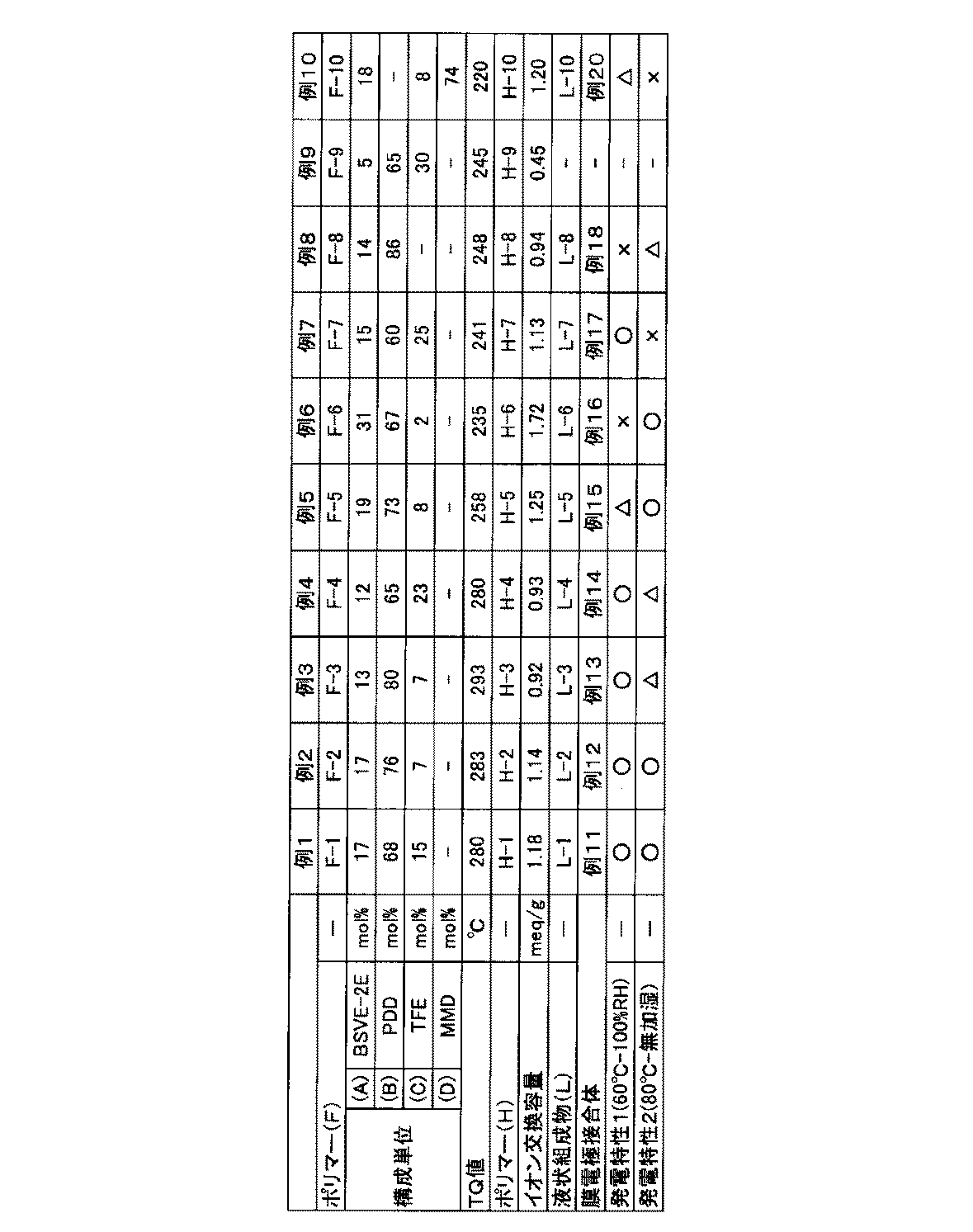
例9は、ポリマー(F)における特定の構成単位(A)の割合が低いため、ポリマー(H)の分散媒への分散性が悪く、液状組成物が得られない。
例16は、ポリマー(F)における特定の構成単位(A)の割合が高いため、低温、高湿条件下における発電特性が不充分である。
例17は、ポリマー(F)における特定の構成単位(B)の割合が低いため、高温、低湿条件下における発電特性が不充分である。
例18は、ポリマー(F)における特定の構成単位(B)の割合が高く、ガラス転移点が高くなりすぎるため、低温、高湿条件下における発電特性が不充分である。
例20は、ポリマー(F)における特定の構成単位(B)の代わりに、他の5員環を有するペルフルオロモノマーに基づく構成単位を採用したため、高温、低湿条件下における発電特性が不充分である。 In Examples 11 to 15, since the polymer (F) has a specific structural unit (A), a specific structural unit (B), and a specific structural unit (C) in specific ratios, The power generation characteristics are good under any of low humidity conditions.
In Example 9, since the proportion of the specific structural unit (A) in the polymer (F) is low, the dispersibility of the polymer (H) in the dispersion medium is poor and a liquid composition cannot be obtained.
In Example 16, since the ratio of the specific structural unit (A) in the polymer (F) is high, the power generation characteristics under low temperature and high humidity conditions are insufficient.
In Example 17, since the ratio of the specific structural unit (B) in the polymer (F) is low, the power generation characteristics under high temperature and low humidity conditions are insufficient.
In Example 18, since the ratio of the specific structural unit (B) in the polymer (F) is high and the glass transition point becomes too high, the power generation characteristics under low temperature and high humidity conditions are insufficient.
Example 20 employs a structural unit based on a perfluoromonomer having another 5-membered ring instead of the specific structural unit (B) in the polymer (F), so that the power generation characteristics under high temperature and low humidity conditions are insufficient. .
Claims (12)
- 下記ポリマー(F)の有する前駆体基をイオン交換基に変換したポリマー(H)からなる、電解質材料。
ポリマー(F):下式(g1)で表される前駆体基を有するペルフルオロモノマーに基づく構成単位(A)と、下式(u2)で表される構成単位(B)と、テトラフルオロエチレンに基づく構成単位(C)とを有し、全構成単位の100モル%のうち、前記構成単位(A)の割合が8~19モル%であり、前記構成単位(B)の割合が65~80モル%であり、前記構成単位(C)の割合が1~27モル%であるポリマー。


Polymer (F): a structural unit (A) based on a perfluoromonomer having a precursor group represented by the following formula (g1), a structural unit (B) represented by the following formula (u2), and tetrafluoroethylene The proportion of the structural unit (A) is 8 to 19 mol% and the proportion of the structural unit (B) is 65 to 80% of 100 mol% of all the structural units. A polymer in which the proportion of the structural unit (C) is 1 to 27 mol%.
- 前記ポリマー(F)を構成する全構成単位の100モル%のうち、前記構成単位(A)の割合が13~18モル%であり、前記構成単位(B)の割合が67~78モル%であり、前記構成単位(C)の割合が4~20モル%である、請求項1に記載の電解質材料。 Of 100 mol% of all the structural units constituting the polymer (F), the proportion of the structural unit (A) is 13 to 18 mol%, and the proportion of the structural unit (B) is 67 to 78 mol%. The electrolyte material according to claim 1, wherein the proportion of the structural unit (C) is 4 to 20 mol%.
- 前記ポリマー(F)の下記TQ値が、250~330℃である、請求項1または2に記載の電解質材料。
TQ値:長さ1mm、内径1mmのノズルを用い、2.94MPaの押出し圧力の条件でポリマー(F)の溶融押出しを行った際の押出し量が100mm3/秒となる温度である。 The electrolyte material according to claim 1 or 2, wherein the polymer (F) has the following TQ value of 250 to 330 ° C.
TQ value: A temperature at which the extrusion amount becomes 100 mm 3 / sec when the polymer (F) is melt-extruded under the condition of an extrusion pressure of 2.94 MPa using a nozzle having a length of 1 mm and an inner diameter of 1 mm. - 前記ポリマー(H)のイオン交換容量は、0.7~1.29ミリ当量/g乾燥樹脂である、請求項1~3に記載の電解質材料。 4. The electrolyte material according to claim 1, wherein the polymer (H) has an ion exchange capacity of 0.7 to 1.29 meq / g dry resin.
- 前構成単位(A)の前駆体基をイオン交換基に変換した構成単位(A’)の少なくとも一種が、下式(u’1)で表わされる構成単位である、請求項1~4のいずれか一項に記載の電解質材料。
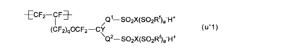
- Q1およびQ2が、それぞれ独立にエーテル結合性酸素原子を有してもよい炭素数1~6のペルフルオロアルキレン基である、請求項1~5のいずれか一項に記載の電解質材料。 The electrolyte material according to any one of claims 1 to 5, wherein Q 1 and Q 2 are each independently a C 1-6 perfluoroalkylene group which may have an etheric oxygen atom.
- Q1およびQ2の少なくとも一方が、エーテル結合性酸素原子を有する炭素数1~6のペルフルオロアルキレン基である、請求項6に記載の電解質材料。 7. The electrolyte material according to claim 6, wherein at least one of Q 1 and Q 2 is a C 1-6 perfluoroalkylene group having an etheric oxygen atom.
- 前記構成単位(B)の少なくとも一種が、下式(u2-1)で表わされる構成単位である、請求項1~7のいずれか一項に記載の電解質材料。

- 分散媒と、該分散媒に分散された請求項1~8のいずれか一項に記載の電解質材料とを含み、前記分散媒が、水酸基を有する有機溶媒を含む、液状組成物。 A liquid composition comprising a dispersion medium and the electrolyte material according to any one of claims 1 to 8 dispersed in the dispersion medium, wherein the dispersion medium comprises an organic solvent having a hydroxyl group.
- 請求項1~8のいずれか一項に記載の電解質材料を1~50質量%含む請求項9に記載の液状組成物。 The liquid composition according to claim 9, comprising 1 to 50% by mass of the electrolyte material according to any one of claims 1 to 8.
- 固体高分子形燃料電池用膜電極接合体の電極の有する触媒層であり、請求項1~8のいずれか一項に記載の電解質材料からなるプロトン伝導性ポリマーを含む触媒層。 A catalyst layer comprising a proton conductive polymer comprising an electrolyte material according to any one of claims 1 to 8, which is a catalyst layer of an electrode of a membrane electrode assembly for a polymer electrolyte fuel cell.
- プロトン伝導性ポリマーを含む触媒層を有するアノードと、
プロトン伝導性ポリマーを含む触媒層を有するカソードと、
前記アノードと前記カソードとの間に配置される固体高分子電解質膜と
を備えた固体高分子形燃料電池用膜電極接合体において、
前記カソードおよび前記アノードの少なくとも一方の触媒層に含まれるプロトン伝導性ポリマーが、請求項1~8のいずれか一項に記載の電解質材料であることを特徴とする固体高分子形燃料電池用膜電極接合体。 An anode having a catalyst layer comprising a proton conducting polymer;
A cathode having a catalyst layer comprising a proton conducting polymer;
In a membrane electrode assembly for a polymer electrolyte fuel cell, comprising: a polymer electrolyte membrane disposed between the anode and the cathode;
The membrane for a polymer electrolyte fuel cell, wherein the proton conductive polymer contained in at least one of the catalyst layer of the cathode and the anode is the electrolyte material according to any one of claims 1 to 8. Electrode assembly.
Priority Applications (5)
| Application Number | Priority Date | Filing Date | Title |
|---|---|---|---|
| JP2016566321A JP6593346B2 (en) | 2014-12-25 | 2015-12-18 | Electrolyte material, liquid composition, and membrane electrode assembly for polymer electrolyte fuel cell |
| KR1020177011963A KR102465033B1 (en) | 2014-12-25 | 2015-12-18 | Electrolyte material, liquid composition, and membrane-electrode assembly for solid polymer fuel cell |
| EP15872948.3A EP3239189B1 (en) | 2014-12-25 | 2015-12-18 | Electrolyte material, liquid composition and membrane/electrode assembly for polymer electrolyte fuel cell |
| CN201580070807.5A CN107108781B (en) | 2014-12-25 | 2015-12-18 | Electrolyte material, liquid composition, and membrane electrode assembly for polymer electrolyte fuel cell |
| US15/627,861 US10879551B2 (en) | 2014-12-25 | 2017-06-20 | Electrolyte material, liquid composition and membrane/electrode assembly for polymer electrolyte fuel cell |
Applications Claiming Priority (2)
| Application Number | Priority Date | Filing Date | Title |
|---|---|---|---|
| JP2014-262600 | 2014-12-25 | ||
| JP2014262600 | 2014-12-25 |
Related Child Applications (1)
| Application Number | Title | Priority Date | Filing Date |
|---|---|---|---|
| US15/627,861 Continuation US10879551B2 (en) | 2014-12-25 | 2017-06-20 | Electrolyte material, liquid composition and membrane/electrode assembly for polymer electrolyte fuel cell |
Publications (1)
| Publication Number | Publication Date |
|---|---|
| WO2016104380A1 true WO2016104380A1 (en) | 2016-06-30 |
Family
ID=56150399
Family Applications (1)
| Application Number | Title | Priority Date | Filing Date |
|---|---|---|---|
| PCT/JP2015/085561 WO2016104380A1 (en) | 2014-12-25 | 2015-12-18 | Electrolyte material, liquid composition, and membrane-electrode assembly for solid polymer fuel cell |
Country Status (6)
| Country | Link |
|---|---|
| US (1) | US10879551B2 (en) |
| EP (1) | EP3239189B1 (en) |
| JP (1) | JP6593346B2 (en) |
| KR (1) | KR102465033B1 (en) |
| CN (1) | CN107108781B (en) |
| WO (1) | WO2016104380A1 (en) |
Cited By (7)
| Publication number | Priority date | Publication date | Assignee | Title |
|---|---|---|---|---|
| WO2018061838A1 (en) * | 2016-09-27 | 2018-04-05 | 旭硝子株式会社 | Polymer, solid polymer electrolyte membrane, and membrane electrode assembly |
| JP2020122068A (en) * | 2019-01-30 | 2020-08-13 | 東ソー株式会社 | Fluorine resin and method for producing the same |
| WO2020184681A1 (en) | 2019-03-13 | 2020-09-17 | Agc株式会社 | Membrane electrode assembly |
| JP2020158712A (en) * | 2019-03-27 | 2020-10-01 | 東ソー株式会社 | Method for producing fluororesin |
| WO2021079904A1 (en) * | 2019-10-21 | 2021-04-29 | Agc株式会社 | Fluorosulfonyl group-containing fluoropolymer and method for producing same, sulfonic acid group-containing fluoropolymer and method for producing same, solid polymer electrolyte membrane, membrane electrode assembly, and solid polymer fuel cell |
| CN114388826A (en) * | 2021-12-17 | 2022-04-22 | 深圳航天科技创新研究院 | Air-cooled fuel cell catalyst layer, preparation method thereof and membrane electrode |
| WO2022210571A1 (en) | 2021-03-29 | 2022-10-06 | Agc株式会社 | Electrolyte material, membrane electrode assembly and polymer electrolyte fuel cell |
Families Citing this family (1)
| Publication number | Priority date | Publication date | Assignee | Title |
|---|---|---|---|---|
| EP3778782B1 (en) * | 2018-04-12 | 2023-02-01 | Agc Inc. | Method for collecting liquid composition |
Citations (4)
| Publication number | Priority date | Publication date | Assignee | Title |
|---|---|---|---|---|
| JPS5838707A (en) * | 1981-08-20 | 1983-03-07 | イ−・アイ・デユポン・デ・ニモアス・アンド・カンパニ− | Amorphous copolymer of perfluoro-2,2-dimethyl- 1,3-dioxol |
| JPH0616725A (en) * | 1992-06-30 | 1994-01-25 | Mitsubishi Rayon Co Ltd | Fluororesin composition |
| WO2011013578A1 (en) * | 2009-07-31 | 2011-02-03 | 旭硝子株式会社 | Electrolyte material, liquid composition, and membrane -electrode assembly for polymer electrolyte fuel cell |
| JP2014507753A (en) * | 2010-12-20 | 2014-03-27 | イー・アイ・デュポン・ドウ・ヌムール・アンド・カンパニー | Ionomer and ion conductive composition for use as one or more electrodes in a fuel cell |
Family Cites Families (8)
| Publication number | Priority date | Publication date | Assignee | Title |
|---|---|---|---|---|
| US4530569A (en) | 1981-08-20 | 1985-07-23 | E. I. Du Pont De Nemours And Company | Optical fibers comprising cores clad with amorphous copolymers of perfluoro-2,2-dimethyl-1,3-dioxole |
| KR950002643B1 (en) * | 1992-07-29 | 1995-03-23 | 대우전자부품주식회사 | Mno2 coating firing method |
| JP5141251B2 (en) * | 2005-07-27 | 2013-02-13 | 旭硝子株式会社 | Fluorosulfonyl group-containing compound, production method thereof and polymer thereof |
| WO2007081538A2 (en) * | 2005-12-21 | 2007-07-19 | E. I. Du Pont De Nemours And Company | Membrane electrode assembly for organic/air fuel cells |
| US20090110967A1 (en) * | 2007-10-31 | 2009-04-30 | Asahi Glass Company Limited | Electrolyte membrane for polymer electrolyte fuel cell, process for its production, membrane/electrode assembly for polymer electrolyte fuel cell and method of operating polymer electrolyte fuel cell |
| WO2009104701A1 (en) * | 2008-02-22 | 2009-08-27 | 旭硝子株式会社 | Method for manufacturing membrane electrode assembly for solid polymer fuel cell |
| WO2010137627A1 (en) * | 2009-05-29 | 2010-12-02 | 旭硝子株式会社 | Electrolyte material, liquid composite, and membrane electrode assembly for solid polymer fuel cells |
| CN104220467B (en) * | 2012-04-16 | 2017-08-04 | 旭硝子株式会社 | Electrolyte, liquid composition and membrane-electrode assembly for polymer electrolyte fuel cell |
-
2015
- 2015-12-18 JP JP2016566321A patent/JP6593346B2/en active Active
- 2015-12-18 EP EP15872948.3A patent/EP3239189B1/en active Active
- 2015-12-18 WO PCT/JP2015/085561 patent/WO2016104380A1/en active Application Filing
- 2015-12-18 CN CN201580070807.5A patent/CN107108781B/en active Active
- 2015-12-18 KR KR1020177011963A patent/KR102465033B1/en active IP Right Grant
-
2017
- 2017-06-20 US US15/627,861 patent/US10879551B2/en active Active
Patent Citations (4)
| Publication number | Priority date | Publication date | Assignee | Title |
|---|---|---|---|---|
| JPS5838707A (en) * | 1981-08-20 | 1983-03-07 | イ−・アイ・デユポン・デ・ニモアス・アンド・カンパニ− | Amorphous copolymer of perfluoro-2,2-dimethyl- 1,3-dioxol |
| JPH0616725A (en) * | 1992-06-30 | 1994-01-25 | Mitsubishi Rayon Co Ltd | Fluororesin composition |
| WO2011013578A1 (en) * | 2009-07-31 | 2011-02-03 | 旭硝子株式会社 | Electrolyte material, liquid composition, and membrane -electrode assembly for polymer electrolyte fuel cell |
| JP2014507753A (en) * | 2010-12-20 | 2014-03-27 | イー・アイ・デュポン・ドウ・ヌムール・アンド・カンパニー | Ionomer and ion conductive composition for use as one or more electrodes in a fuel cell |
Non-Patent Citations (1)
| Title |
|---|
| See also references of EP3239189A4 * |
Cited By (11)
| Publication number | Priority date | Publication date | Assignee | Title |
|---|---|---|---|---|
| WO2018061838A1 (en) * | 2016-09-27 | 2018-04-05 | 旭硝子株式会社 | Polymer, solid polymer electrolyte membrane, and membrane electrode assembly |
| US11031618B2 (en) | 2016-09-27 | 2021-06-08 | AGC Inc. | Polymer, polymer electrolyte membrane and membrane/electrode assembly |
| JP2020122068A (en) * | 2019-01-30 | 2020-08-13 | 東ソー株式会社 | Fluorine resin and method for producing the same |
| JP7451871B2 (en) | 2019-01-30 | 2024-03-19 | 東ソー株式会社 | Fluororesin and its manufacturing method |
| WO2020184681A1 (en) | 2019-03-13 | 2020-09-17 | Agc株式会社 | Membrane electrode assembly |
| JP7416047B2 (en) | 2019-03-13 | 2024-01-17 | Agc株式会社 | membrane electrode assembly |
| JP2020158712A (en) * | 2019-03-27 | 2020-10-01 | 東ソー株式会社 | Method for producing fluororesin |
| JP7295507B2 (en) | 2019-03-27 | 2023-06-21 | 東ソー株式会社 | Method for producing fluororesin |
| WO2021079904A1 (en) * | 2019-10-21 | 2021-04-29 | Agc株式会社 | Fluorosulfonyl group-containing fluoropolymer and method for producing same, sulfonic acid group-containing fluoropolymer and method for producing same, solid polymer electrolyte membrane, membrane electrode assembly, and solid polymer fuel cell |
| WO2022210571A1 (en) | 2021-03-29 | 2022-10-06 | Agc株式会社 | Electrolyte material, membrane electrode assembly and polymer electrolyte fuel cell |
| CN114388826A (en) * | 2021-12-17 | 2022-04-22 | 深圳航天科技创新研究院 | Air-cooled fuel cell catalyst layer, preparation method thereof and membrane electrode |
Also Published As
| Publication number | Publication date |
|---|---|
| KR20170100482A (en) | 2017-09-04 |
| US20170288249A1 (en) | 2017-10-05 |
| CN107108781B (en) | 2020-08-11 |
| EP3239189B1 (en) | 2021-04-28 |
| JPWO2016104380A1 (en) | 2017-11-02 |
| CN107108781A (en) | 2017-08-29 |
| JP6593346B2 (en) | 2019-10-23 |
| KR102465033B1 (en) | 2022-11-08 |
| EP3239189A4 (en) | 2018-07-11 |
| US10879551B2 (en) | 2020-12-29 |
| EP3239189A1 (en) | 2017-11-01 |
Similar Documents
| Publication | Publication Date | Title |
|---|---|---|
| JP5609874B2 (en) | Electrolyte material, liquid composition, and membrane electrode assembly for polymer electrolyte fuel cell | |
| JP6593346B2 (en) | Electrolyte material, liquid composition, and membrane electrode assembly for polymer electrolyte fuel cell | |
| JP5286797B2 (en) | Polymer, polymer electrolyte membrane for polymer electrolyte fuel cell and membrane electrode assembly | |
| JP6172142B2 (en) | Electrolyte material, liquid composition, and membrane electrode assembly for polymer electrolyte fuel cell | |
| WO2011013577A1 (en) | Electrolyte material, liquid composition, and membrane electrode assembly for solid polymer fuel cells | |
| JP5565410B2 (en) | Electrolyte material, liquid composition, and membrane electrode assembly for polymer electrolyte fuel cell | |
| WO2014175123A1 (en) | Electrolyte material, liquid composition, and membrane electrode assembly for solid polymer fuel cells | |
| JP5499478B2 (en) | Polymer, polymer electrolyte membrane for polymer electrolyte fuel cell and membrane electrode assembly | |
| JP6947175B2 (en) | Electrolyte material, its manufacturing method and its use | |
| JP6856073B2 (en) | Electrolyte material, liquid composition containing it and its use | |
| WO2018061838A1 (en) | Polymer, solid polymer electrolyte membrane, and membrane electrode assembly | |
| WO2016002889A1 (en) | Electrolyte material, liquid composition, membrane electrode assembly for solid polymer fuel cell, and fluorine-containing branched polymer | |
| JP5521427B2 (en) | Fuel cell system | |
| US20160293987A1 (en) | Liquid composition, method for its production, and method for producing membrane/electrode assembly for polymer electrolyte fuel cell |
Legal Events
| Date | Code | Title | Description |
|---|---|---|---|
| 121 | Ep: the epo has been informed by wipo that ep was designated in this application |
Ref document number: 15872948 Country of ref document: EP Kind code of ref document: A1 |
|
| ENP | Entry into the national phase |
Ref document number: 20177011963 Country of ref document: KR Kind code of ref document: A |
|
| ENP | Entry into the national phase |
Ref document number: 2016566321 Country of ref document: JP Kind code of ref document: A |
|
| REEP | Request for entry into the european phase |
Ref document number: 2015872948 Country of ref document: EP |
|
| NENP | Non-entry into the national phase |
Ref country code: DE |