WO2016104033A1 - State calculating apparatus, state calculating method and state calculating program - Google Patents
State calculating apparatus, state calculating method and state calculating program Download PDFInfo
- Publication number
- WO2016104033A1 WO2016104033A1 PCT/JP2015/083154 JP2015083154W WO2016104033A1 WO 2016104033 A1 WO2016104033 A1 WO 2016104033A1 JP 2015083154 W JP2015083154 W JP 2015083154W WO 2016104033 A1 WO2016104033 A1 WO 2016104033A1
- Authority
- WO
- WIPO (PCT)
- Prior art keywords
- gnss
- antenna
- calculated
- calculation
- speed
- Prior art date
Links
Images


Classifications
-
- G—PHYSICS
- G01—MEASURING; TESTING
- G01S—RADIO DIRECTION-FINDING; RADIO NAVIGATION; DETERMINING DISTANCE OR VELOCITY BY USE OF RADIO WAVES; LOCATING OR PRESENCE-DETECTING BY USE OF THE REFLECTION OR RERADIATION OF RADIO WAVES; ANALOGOUS ARRANGEMENTS USING OTHER WAVES
- G01S19/00—Satellite radio beacon positioning systems; Determining position, velocity or attitude using signals transmitted by such systems
- G01S19/38—Determining a navigation solution using signals transmitted by a satellite radio beacon positioning system
- G01S19/39—Determining a navigation solution using signals transmitted by a satellite radio beacon positioning system the satellite radio beacon positioning system transmitting time-stamped messages, e.g. GPS [Global Positioning System], GLONASS [Global Orbiting Navigation Satellite System] or GALILEO
- G01S19/53—Determining attitude
- G01S19/54—Determining attitude using carrier phase measurements; using long or short baseline interferometry
- G01S19/55—Carrier phase ambiguity resolution; Floating ambiguity; LAMBDA [Least-squares AMBiguity Decorrelation Adjustment] method
-
- G—PHYSICS
- G01—MEASURING; TESTING
- G01S—RADIO DIRECTION-FINDING; RADIO NAVIGATION; DETERMINING DISTANCE OR VELOCITY BY USE OF RADIO WAVES; LOCATING OR PRESENCE-DETECTING BY USE OF THE REFLECTION OR RERADIATION OF RADIO WAVES; ANALOGOUS ARRANGEMENTS USING OTHER WAVES
- G01S19/00—Satellite radio beacon positioning systems; Determining position, velocity or attitude using signals transmitted by such systems
- G01S19/38—Determining a navigation solution using signals transmitted by a satellite radio beacon positioning system
- G01S19/39—Determining a navigation solution using signals transmitted by a satellite radio beacon positioning system the satellite radio beacon positioning system transmitting time-stamped messages, e.g. GPS [Global Positioning System], GLONASS [Global Orbiting Navigation Satellite System] or GALILEO
- G01S19/42—Determining position
- G01S19/48—Determining position by combining or switching between position solutions derived from the satellite radio beacon positioning system and position solutions derived from a further system
- G01S19/49—Determining position by combining or switching between position solutions derived from the satellite radio beacon positioning system and position solutions derived from a further system whereby the further system is an inertial position system, e.g. loosely-coupled
-
- G—PHYSICS
- G01—MEASURING; TESTING
- G01C—MEASURING DISTANCES, LEVELS OR BEARINGS; SURVEYING; NAVIGATION; GYROSCOPIC INSTRUMENTS; PHOTOGRAMMETRY OR VIDEOGRAMMETRY
- G01C21/00—Navigation; Navigational instruments not provided for in groups G01C1/00 - G01C19/00
- G01C21/10—Navigation; Navigational instruments not provided for in groups G01C1/00 - G01C19/00 by using measurements of speed or acceleration
- G01C21/12—Navigation; Navigational instruments not provided for in groups G01C1/00 - G01C19/00 by using measurements of speed or acceleration executed aboard the object being navigated; Dead reckoning
- G01C21/16—Navigation; Navigational instruments not provided for in groups G01C1/00 - G01C19/00 by using measurements of speed or acceleration executed aboard the object being navigated; Dead reckoning by integrating acceleration or speed, i.e. inertial navigation
- G01C21/165—Navigation; Navigational instruments not provided for in groups G01C1/00 - G01C19/00 by using measurements of speed or acceleration executed aboard the object being navigated; Dead reckoning by integrating acceleration or speed, i.e. inertial navigation combined with non-inertial navigation instruments
-
- G—PHYSICS
- G01—MEASURING; TESTING
- G01S—RADIO DIRECTION-FINDING; RADIO NAVIGATION; DETERMINING DISTANCE OR VELOCITY BY USE OF RADIO WAVES; LOCATING OR PRESENCE-DETECTING BY USE OF THE REFLECTION OR RERADIATION OF RADIO WAVES; ANALOGOUS ARRANGEMENTS USING OTHER WAVES
- G01S13/00—Systems using the reflection or reradiation of radio waves, e.g. radar systems; Analogous systems using reflection or reradiation of waves whose nature or wavelength is irrelevant or unspecified
- G01S13/74—Systems using reradiation of radio waves, e.g. secondary radar systems; Analogous systems
- G01S13/82—Systems using reradiation of radio waves, e.g. secondary radar systems; Analogous systems wherein continuous-type signals are transmitted
- G01S13/84—Systems using reradiation of radio waves, e.g. secondary radar systems; Analogous systems wherein continuous-type signals are transmitted for distance determination by phase measurement
-
- G—PHYSICS
- G01—MEASURING; TESTING
- G01S—RADIO DIRECTION-FINDING; RADIO NAVIGATION; DETERMINING DISTANCE OR VELOCITY BY USE OF RADIO WAVES; LOCATING OR PRESENCE-DETECTING BY USE OF THE REFLECTION OR RERADIATION OF RADIO WAVES; ANALOGOUS ARRANGEMENTS USING OTHER WAVES
- G01S19/00—Satellite radio beacon positioning systems; Determining position, velocity or attitude using signals transmitted by such systems
- G01S19/38—Determining a navigation solution using signals transmitted by a satellite radio beacon positioning system
- G01S19/39—Determining a navigation solution using signals transmitted by a satellite radio beacon positioning system the satellite radio beacon positioning system transmitting time-stamped messages, e.g. GPS [Global Positioning System], GLONASS [Global Orbiting Navigation Satellite System] or GALILEO
- G01S19/53—Determining attitude
- G01S19/54—Determining attitude using carrier phase measurements; using long or short baseline interferometry
-
- G—PHYSICS
- G01—MEASURING; TESTING
- G01S—RADIO DIRECTION-FINDING; RADIO NAVIGATION; DETERMINING DISTANCE OR VELOCITY BY USE OF RADIO WAVES; LOCATING OR PRESENCE-DETECTING BY USE OF THE REFLECTION OR RERADIATION OF RADIO WAVES; ANALOGOUS ARRANGEMENTS USING OTHER WAVES
- G01S19/00—Satellite radio beacon positioning systems; Determining position, velocity or attitude using signals transmitted by such systems
- G01S19/38—Determining a navigation solution using signals transmitted by a satellite radio beacon positioning system
- G01S19/39—Determining a navigation solution using signals transmitted by a satellite radio beacon positioning system the satellite radio beacon positioning system transmitting time-stamped messages, e.g. GPS [Global Positioning System], GLONASS [Global Orbiting Navigation Satellite System] or GALILEO
- G01S19/42—Determining position
- G01S19/45—Determining position by combining measurements of signals from the satellite radio beacon positioning system with a supplementary measurement
- G01S19/47—Determining position by combining measurements of signals from the satellite radio beacon positioning system with a supplementary measurement the supplementary measurement being an inertial measurement, e.g. tightly coupled inertial
-
- G—PHYSICS
- G01—MEASURING; TESTING
- G01S—RADIO DIRECTION-FINDING; RADIO NAVIGATION; DETERMINING DISTANCE OR VELOCITY BY USE OF RADIO WAVES; LOCATING OR PRESENCE-DETECTING BY USE OF THE REFLECTION OR RERADIATION OF RADIO WAVES; ANALOGOUS ARRANGEMENTS USING OTHER WAVES
- G01S5/00—Position-fixing by co-ordinating two or more direction or position line determinations; Position-fixing by co-ordinating two or more distance determinations
- G01S5/02—Position-fixing by co-ordinating two or more direction or position line determinations; Position-fixing by co-ordinating two or more distance determinations using radio waves
- G01S5/0284—Relative positioning
Definitions
- the present invention relates to a state calculation device, a state calculation method, and a state calculation program for calculating a navigation state such as an attitude angle, a speed, and a position in a moving body such as a ship, a flying body, and an automobile.
- Non-Patent Document 1 describes a configuration including a plurality of GPS (Global Positioning System) antennas, a plurality of GPS receivers connected to the plurality of GPS antennas, an IMU sensor, and an integrated processing unit.
- GPS Global Positioning System
- the plurality of GPS antennas receive GPS signals transmitted by GPS satellites and output them to the GPS receiver.
- the plurality of GPS antennas are composed of a master GPS antenna and a plurality of slave GPS antennas.
- the master GPS antenna and the plurality of slave GPS antennas are arranged on the moving body so that the distance between the master GPS antenna and the slave GPS antenna is as long as possible. This is because it is known that the longer the distance (baseline length) between GPS antennas, the more accurately the calculated state value of the moving body can be detected.
- the state calculation value of the moving body is, for example, the posture angle of the moving body.
- the GPS receiver calculates and outputs the pseudorange, ⁇ range, and carrier wave phase of the received GPS signal.
- the IMU sensor includes an angular velocity sensor and an acceleration sensor, and measures and outputs the angular velocity and acceleration of the moving body.
- the integrated processing unit calculates the speed, acceleration, and posture angle of the moving body based on the angular velocity and acceleration from the IMU sensor. At this time, the integration processing unit corrects errors in the calculated position, velocity, and attitude angle using the pseudoranges, ⁇ ranges, and carrier wave phases obtained from the plurality of GPS receivers.
- Non-Patent Document 2 describes that a double phase difference is calculated using four GNSS antennas, and a position, velocity, and attitude angle are calculated using the double phase difference.
- one GNSS antenna is set as a reference antenna, and a baseline vector is set.
- Non-Patent Document 1 when the configuration described in Non-Patent Document 1 described above is used, it is necessary to increase the distance between the GPS antennas, so that the overall shape of the state calculation device becomes large. For this reason, for example, when the installation position of the GPS antenna is restricted, there arises a problem that the GPS antenna cannot be installed or a highly accurate state calculation value cannot be acquired.
- Non-Patent Document 2 since one of a plurality of arranged GNSS antennas is set as a reference antenna, the number of base lines that can be formed is limited depending on the number of GNSS antennas. Therefore, if an attempt is made to increase the number of base lines in order to improve accuracy, the number of antennas must be increased by at least the number of base lines, which hinders downsizing.
- an object of the present invention is to provide a small state calculation device capable of obtaining a highly accurate state calculation value.
- the state calculation apparatus of the present invention includes first, second, and third GNSS antennas that receive a GNSS signal, first, second, and third GNSS reception units, a phase difference calculation unit, and a calculation unit. .
- the first GNSS receiver calculates the carrier phase of the GNSS signal received by the first GNSS antenna.
- the second GNSS receiver calculates the carrier phase of the GNSS signal received by the second GNSS antenna.
- the third GNSS receiver calculates the carrier phase of the GNSS signal received by the third GNSS antenna.
- the phase difference calculation unit selects two of the first GNSS antenna, the second GNSS antenna, and the third GNSS antenna, and selects a combination of a master antenna and a slave antenna that are different in at least one master antenna.
- the calculation unit calculates a posture angle using a plurality of inter-antenna phase differences calculated for each combination.
- This configuration can increase the number of inter-antenna phase differences used for posture angle estimation calculation. Thereby, the estimation accuracy of the posture angle can be improved.
- the calculation unit of the state calculation device of the present invention includes an error calculation unit and an integration processing unit.
- the error calculation unit estimates a posture angle calculation error using the geometric distance difference obtained from the inter-antenna phase difference and the geometric distance difference based on the past posture angle calculated by the integration processing unit.
- the integrated processing unit calculates the posture angle using the angular velocity or acceleration measured by the inertial sensor and the calculation error of the posture angle.
- the measured value of the inertial sensor can also be used, so that the posture angle can be output stably. Furthermore, since a posture angle calculation error can be estimated by a highly accurate posture angle using the above-described GNSS signal, a more accurate posture angle can be output.
- the calculation unit of the state calculation device of the present invention includes an error calculation unit and an integration processing unit.
- the error calculation unit estimates a posture angle calculation error using the geometric distance difference and the geometric distance difference based on the past posture angle calculated by the integration processing unit. At this time, the error calculation unit estimates the position and velocity calculation errors as well as the posture angle.
- the integrated processing unit calculates the posture angle, the position, and the velocity using the angular velocity or acceleration measured by the inertial sensor, the calculation error of the posture angle, the position calculation error, and the velocity calculation error.
- the state calculation device further includes a position calculation unit and a speed calculation unit.
- the position calculator calculates the position of the first GNSS antenna calculated by the first GNSS receiver, the position of the second GNSS antenna calculated by the second GNSS receiver, and the third GNSS receiver.
- the position of the specific point is calculated using the position of the third GNSS antenna.
- the speed calculation unit calculates the speed of the first GNSS antenna calculated by the first GNSS receiver, the speed of the second GNSS antenna calculated by the second GNSS receiver, and the third GNSS receiver.
- the speed of the specific point is calculated using the speed of the third GNSS antenna.
- the error estimation unit calculates the position calculation error using the position of the specific point and the past position of the specific point calculated by the integration processing unit, or the speed of the specific point and the past speed of the specific point calculated by the integration processing unit. And a speed calculation error using.
- the processing load of the error estimation process can be reduced by using the specific position and the specific speed calculated by the process different from the error estimation process for the error estimation process.
- the posture angle is a yaw angle. With this configuration, it is possible to calculate with high accuracy the direction in which the moving body is facing.
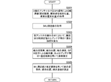
- the flowchart of the state calculation method which concerns on the 1st Embodiment of this invention The flowchart which shows the specific process of step S106 of FIG.
- the flowchart of the state calculation method which concerns on the 1st Embodiment of this invention The flowchart which shows the specific process of step S206 of FIG.
- a state calculation device, a state calculation method, and a state calculation program according to the first embodiment of the present invention will be described with reference to the drawings.
- an apparatus for calculating the navigation state of the ship will be described using the mobile body as a ship.
- other sea mobile bodies, underwater mobile bodies, land mobile bodies such as automobiles, and mobile states of air mobile bodies such as airplanes The following configuration can also be applied to the case of calculating.
- FIG. 1 is a block diagram showing a configuration of a state calculation apparatus according to the first embodiment of the present invention.
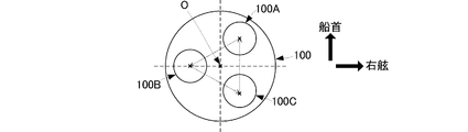
- FIG. 2 is a diagram showing the positional relationship of the antennas used in the state calculation device according to the first embodiment of the present invention.
- the state calculation device 10 includes an antenna unit 100, reception units 11A, 11B, and 11C, a phase calculation unit 12, and a calculation unit 13.
- the antenna unit 100 includes a first antenna 100A, a second antenna 100B, and a third antenna 100C.
- the antenna unit 100 is disposed at a position where the sky in the hull is open.
- the first antenna 100A corresponds to a first GNSS antenna
- the second antenna 100B corresponds to a second GNSS antenna
- the third antenna 100C corresponds to a third GNSS antenna.
- the arrangement pattern of the first antenna 100A, the second antenna 100B, and the third antenna 100C has a two-dimensional spread.
- the first antenna 100A and the third antenna 100C have a base line connecting these antennas parallel to the direction connecting the bow and the stern (the bow-stern direction). It is arranged to be.
- the second antenna 100B is arranged at a position different from a base line connecting the first antenna 100A and the third antenna 100C and a straight line extending from the base line.
- the second antenna 100B is arranged between the first antenna 100A and the third antenna 100C in the bow-stern direction.
- the second antenna 100B is arranged at a distance from the base line in a direction orthogonal to the base line connecting the first antenna 100A and the third antenna 100C.
- the second antenna 100B is disposed at an equidistant position with respect to the first antenna 100A and the third antenna 100C.
- the distance between the first antenna 100A and the second antenna 100B, the distance between the second antenna 100B and the third antenna 100C, and the distance between the third antenna 100C and the first antenna 100A are short. Thereby, the freedom degree of arrangement
- the integer value bias can be easily determined.
- the distance between these antennas is preferably less than the length of the wavelength ⁇ of the GPS signal, and more preferably about 1 ⁇ 2 ( ⁇ / 2). By setting the distance between the antennas to about ⁇ / 2, it is possible to further easily determine the integer value bias.
- This arrangement is only an example, and it is sufficient that three or more antennas are arranged so as to have a two-dimensional spread.
- the first, second, and third antennas 100A, 100B, and 100C receive and output GPS signals transmitted by GPS (Global Positioning System) satellites.
- GPS Global Positioning System
- this embodiment shows GPS as an example, the configuration of this embodiment can be applied to other systems of GNSS (Global Navigation Satellite System).
- the receiving unit 11A corresponds to a first GNSS receiving unit, and is connected to the first antenna 100A.
- the receiving unit 11A captures and tracks a GPS signal, and calculates a pseudorange for each GPS signal (for each GPS satellite).
- the reception unit 11A calculates the position PO A of the first antenna 100A (the position of the point A shown in FIG. 1) PO A from the pseudo distance using a single positioning method.
- the receiving unit 11A outputs the position PO A of the first antenna 100A to the calculation unit 13.
- Receiving unit 11A calculates a carrier phase measurements PY A for each GPS signal (each GPS satellite).
- the reception unit 11A outputs the carrier phase measurement value PY A to the phase difference calculation unit 12.
- the receiving unit 11B corresponds to a second GNSS receiving unit and is connected to the second antenna 100B.
- the receiving unit 11B captures and tracks a GPS signal, and calculates a pseudorange for each GPS signal (for each GPS satellite).
- the reception unit 11B calculates the position (position B point shown in FIG. 1) PO B of the second antenna 100B from the pseudo distance using a single positioning method.
- the receiving unit 11B outputs the position PO B of the second antenna 100B to the calculation unit 13.
- the receiving unit 11B calculates the carrier phase measurement value PY B for each GPS signal (for each GPS satellite).
- the receiving unit 11B outputs the carrier phase measurement value PY B to the phase difference calculation unit 12.
- the receiving unit 11C corresponds to a third GNSS receiving unit, and is connected to the third antenna 100C.
- the receiving unit 11C captures and tracks a GPS signal, and calculates a pseudorange for each GPS signal (for each GPS satellite).
- Receiving unit 11C a pseudo-range by using a single positioning method, the third position of the antenna 100C (point C shown in FIG. 1 position) and calculates the PO C.
- Receiving unit 11C calculates a carrier phase measurements PY C every GPS signals (each GPS satellite).
- the receiving unit 11C outputs the carrier wave phase measurement value PY C to the phase difference calculating unit 12.
- the receiving units 11A, 11B, and 11C are synchronized. For example, a common clock signal is input to the receiving units 11A, 11B, and 11C, and the receiving units 11A, 11B, and 11C capture and track GPS signals in synchronization with the clock signal.
- the phase difference calculation unit 12 calculates the inter-antenna phase difference for each combination by combining two of the first, second, and third antennas 100A, 100B, and 100C. At this time, the phase difference calculation unit 12 sets one antenna as either a master antenna or a slave antenna depending on the combination, and calculates an inter-antenna phase difference.
- the combination may be determined by permutation (P: permeation) or may be determined by combination (C: combination). Specifically, the phase difference calculation unit 12 executes the following process.
- the phase difference calculation unit 12 sets the first antenna 100A as a master antenna and the second antenna 100B as a slave antenna as the first combination.
- the phase difference calculation unit 12 sets the second antenna 100B as a master antenna and sets the third antenna 100C as a slave antenna.
- the phase difference calculation unit 12 sets the third antenna 100C as a master antenna and sets the first antenna 100A as a slave antenna.
- the phase difference calculation unit 12 outputs the inter-antenna phase differences ⁇ AB , ⁇ BC , ⁇ CA to the calculation unit 13.
- the calculation unit 13 analyzes the navigation message superimposed on the GPS signal and acquires the satellite position.
- the calculating part 13 should just acquire the position of the GPS satellite which is the transmission source of the GPS signal currently received by receiving part 11A, 11B, 11C at least.
- the calculation unit 13 calculates the direction cosine for each of the inter-antenna phase differences ⁇ AB , ⁇ BC , ⁇ CA using the satellite position and the first, second, and third antenna positions PO A , PO B , PO C. To do.
- the calculation unit 13 is a satellite of a GPS satellite that is a transmission source of GPS signals received by the first and second antenna positions P OA and P OB and both the first antenna 100A and the second antenna 100B. Using the position, the direction cosine corresponding to the inter-antenna phase difference ⁇ AB is calculated.
- the calculation unit 13 uses the second and third antenna positions P OB and P OC and the satellite position of the GPS satellite that is the source of the GPS signal received by both the second antenna 100B and the third antenna 100C. A direction cosine corresponding to the inter-antenna phase difference ⁇ BC is calculated. The calculation unit 13 uses the third and first antenna positions P OC and P OA and the satellite position of the GPS satellite that is the transmission source of the GPS signal received by both the third antenna 100C and the first antenna 100A, A direction cosine corresponding to the inter-antenna phase difference ⁇ CA is calculated. The calculation unit 13 sets a direction cosine matrix using each direction cosine.
- the calculation unit 13 calculates the attitude angle AT using the inter-antenna phase differences ⁇ AB , ⁇ BC , ⁇ CA and the direction cosine matrix.
- the attitude angle AT is composed of a roll angle ⁇ , a pitch angle ⁇ , and a yaw angle ⁇ . Note that at least the yaw angle ⁇ may be calculated as the attitude angle AT.
- the calculation unit 13 estimates and determines an integer value bias for each of the inter-antenna phase differences ⁇ AB , ⁇ BC , and ⁇ CA using a known method such as the LAMDA method.
- the calculation unit 13 calculates geometric distance differences corresponding to the inter-antenna phase differences ⁇ AB , ⁇ BC , ⁇ CA using the inter-antenna phase differences ⁇ AB , ⁇ BC , ⁇ CA and the integer value bias.
- the calculation unit 13 calculates the posture angle AT by applying the least square method or the like using the geometric distance difference and the direction cosine matrix.
- the attitude angle can be calculated with high accuracy even if the distance between the first, second, and third antennas 100A, 100B, and 100C is short.
- the posture angle can be calculated even if one of the first, second, and third antennas 100A, 100B, and 100C cannot receive the GPS signal, so that the robustness is improved. Can do.
- the antenna unit 100 can be reduced in size by shortening the distance between the first, second, and third antennas 100A, 100B, and 100C. Thereby, it is hard to receive the restriction
- phase difference calculation part 12 and the calculating part 13 another function part.
- the reception units 11A, 11B, 11C, the phase difference calculation unit 12, and the calculation unit 13 may be formed by one information processing apparatus.
- a program for realizing the state calculation method shown below is stored in advance, and the information processing apparatus may read and execute this program.
- FIG. 3 is a flowchart of the state calculation method according to the first embodiment of the present invention.
- FIG. 4 is a flowchart showing a specific process of step S106 of FIG. 3 and 4 show a case where a single phase difference is used.
- the information processing apparatus captures and tracks GPS signals received by the first, second, and third antennas 100A, 100B, and 100C.
- the information processing apparatus calculates the positions PO A , PO B , PO C and the carrier phase measurement values PY A , PY B , PY C of the first, second, and third antennas 100A, 100B, 100C (S101).
- the information processing apparatus sets a plurality of combinations of antennas by combining the first, second, and third antennas 100A, 100B, and 100C by setting a master antenna and a slave antenna (S102). At this time, the information processing apparatus sets each antenna as a master antenna and a slave antenna. As a result, a combination in which one antenna is set as a master antenna and a combination set as a slave antenna can be realized.
- the information processing apparatus calculates inter-antenna phase differences ⁇ AB , ⁇ BC , ⁇ CA that are single phase differences between the antennas using the carrier phase measurement values PY A , PY B , and PY C for each antenna combination.
- the single phase difference between the antennas is a phase difference between GPS signals received by each antenna when the two antennas receive a GPS signal from a common GPS satellite.
- the information processing apparatus analyzes the navigation message superimposed on the tracking GPS signal and acquires the satellite position (S104).
- the information processing apparatus calculates a direction cosine from the positions PO A , PO B , PO C of the first, second, and third antennas 100A, 100B, and 100C and the satellite position for each combination of antennas, and generates a direction cosine matrix. Is set (S105).
- the information processing apparatus calculates the attitude angle AT by applying the least square method or the like using the inter-antenna phase differences ⁇ AB , ⁇ BC , ⁇ CA and the direction cosine matrix (S106).
- the information processing apparatus calculates integer value biases corresponding to the inter-antenna phase differences ⁇ AB , ⁇ BC , and ⁇ CA (S161).
- the integer value bias can be calculated quickly and reliably by shortening the distance between the first, second, and third antennas 100A, 100B, and 100C.
- the integer value bias can be calculated more quickly and accurately. it can.
- the information processing apparatus calculates the geometric distance difference from the inter-antenna phase differences ⁇ AB , ⁇ BC , ⁇ CA and the integer value bias (S 162).
- the geometric distance difference is a difference between the geometric distance between one antenna and a GPS satellite and the geometric distance between the other antenna and the GPS satellite in two antennas that receive a common GPS signal.
- the information processing apparatus calculates a posture angle by applying a least square method or the like using the geometric distance difference and the direction cosine matrix (S163).
- FIG. 5 is a flowchart of the state calculation method according to the first embodiment of the present invention.
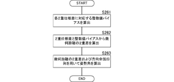
- FIG. 6 is a flowchart showing a specific process of step S206 of FIG. 5 and 6 show a case where a double phase difference is used.
- the information processing apparatus captures and tracks the GPS signals received by the first, second, and third antennas 100A, 100B, and 100C.
- the information processing apparatus calculates the positions PO A , PO B , PO C and the carrier phase measurement values PY A , PY B , PY C of the first, second, and third antennas 100A, 100B, 100C (S201).
- the information processing apparatus sets a plurality of combinations of antennas by combining a master antenna and a slave antenna for the first, second, and third antennas 100A, 100B, and 100C (S202). At this time, the information processing apparatus sets each antenna as a master antenna and a slave antenna. As a result, a combination in which one antenna is set as a master antenna and a combination set as a slave antenna can be realized.
- the information processing apparatus calculates a double phase difference using the carrier phase measurement values PY A , PY B , and PY C in each antenna combination (S103).
- the double phase difference is a phase difference when receiving GPS signals from two GPS satellites in common with two antennas. Specifically, the difference between the phase difference between the two antennas for one GPS satellite and the phase difference between the two antennas for the other GPS satellite.
- the information processing apparatus analyzes the navigation message superimposed on the tracking GPS signal and acquires the satellite position (S204).
- the information processing apparatus calculates a direction cosine from the positions PO A , PO B , PO C of the first, second, and third antennas 100A, 100B, and 100C and the satellite position for each combination of antennas, and generates a direction cosine matrix. Is set (S205).
- the information processing apparatus sets a Kalman filter using the double phase difference and the direction cosine matrix, and estimates the posture angle AT (S206).
- the information processing apparatus calculates an integer value bias corresponding to each of the double phase differences (S261).
- the integer value bias can be calculated quickly and reliably by shortening the distance between the first, second, and third antennas 100A, 100B, and 100C.
- the integer value bias can be calculated more quickly and accurately. it can.
- the information processing apparatus calculates a double difference in geometric distance (difference in geometric distance difference) from the double phase difference and the integer value bias (S262).
- the information processing apparatus calculates the posture angle by applying the least square method or the like using the double difference of the geometric distance and the direction cosine matrix (S263).
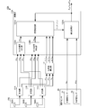
- FIG. 7 is a block diagram of a state calculation apparatus according to the second embodiment of the present invention.
- the state calculation device 10 is an aspect that estimates the attitude angle based only on the GPS signal
- the state calculation device 10A according to the present embodiment further includes an inertial sensor 20.
- the posture angle is calculated using the output angular velocity ⁇ IMU and acceleration a IMU .
- the state calculation device 10A according to the present embodiment calculates the attitude angle, the position, and the velocity using the observation value based on the GPS signal, the angular velocity ⁇ IMU, and the acceleration a IMU .
- the state calculation device 10A according to the present embodiment is different from the state calculation device 10 according to the first embodiment in the configuration of the arithmetic unit 13A, and the basic configuration of other parts is the first embodiment. This is the same as the state calculation device 10 according to the embodiment.
- the state calculation device 10 ⁇ / b> A is connected to the inertial sensor 20.
- the inertial sensor 20 may be included in the state calculation device 10A.
- the inertial sensor 20 includes an acceleration sensor 21 and an angular velocity sensor 22.
- the acceleration sensor 21 measures the acceleration a IMU of the moving object.
- the angular velocity sensor 22 measures the angular velocity ⁇ IMU of the moving object.
- the calculation unit 13A includes an error estimation unit 131A, an integration processing unit 132A, a GNSS speed calculation unit 133A, and a GNSS position calculation unit 134A.
- the receiving unit 11A calculates the position PO A , the speed PV A, and the carrier wave phase PY A of the first antenna 100A.
- the receiving unit 11A outputs the position PO A of the first antenna 100A to the GNSS position calculating unit 134A.
- Receiver 11A outputs the speed PV A of the first antenna 100A to GNSS speed calculation unit 133A.
- the receiving unit 11A outputs the carrier phase measurement value PY A at the first antenna 100A to the phase difference calculating unit 12.
- the receiving unit 11B calculates the position PO B , the speed PV B, and the carrier wave phase PY B of the second antenna 100B.
- the receiving unit 11B outputs the position PO B of the second antenna 100B to the GNSS position calculating unit 134A.
- the reception unit 11B outputs the speed PV B of the second antenna 100B to the GNSS speed calculation unit 133A.
- the receiving unit 11B outputs the carrier phase measurement value PY B at the second antenna 100B to the phase difference calculating unit 12.
- Receiving unit 11C the position PO C of the third antenna 100C, calculate the velocity PV C and carrier phase PY C.
- Receiving unit 11C outputs the position PO C of the third antenna 100C on the GNSS position calculation unit 134A.
- Receiving unit 11C outputs the speed PV C of the third antenna 100C on the GNSS speed calculation unit 133A.
- Receiving unit 11C outputs the carrier phase measurements PY C in the third antenna 100C on the phase difference calculation section 12.
- the phase difference calculation unit 12 outputs the inter-antenna phase differences ⁇ AB , ⁇ BC , ⁇ CA calculated using the carrier phase measurement values PY A , PY B , and PY C to the error estimation unit 131A.
- GNSS speed calculation unit 133A the speed PV A, PV B, using a PV C, is calculated first, second, third antenna 100A, 100B, the speed PV O at a specific position of the movable body 100C is mounted .
- the specific position is a center position O of the first, second, and third antennas 100A, 100B, and 100C when the antenna unit 100 is viewed in plan.
- Speed PV O at a specific position for example, the specific position and the first, second, third antenna 100A, first using 100B, the distance between 100C, second, third antenna 100A, 100B, 100C speed PV of a, PV B, is calculated by weighted averaging of PV C.
- GNSS speed calculation unit 133A outputs the speed PV O at a specific position in the error estimating unit 131A.
- the GNSS position calculation unit 134A uses the positions PO A , PO B , and PO C to specify the position (coordinates) PO O of the specific position of the moving body on which the first, second, and third antennas 100A, 100B, and 100C are mounted. Is calculated. Position PO O at a specific position, for example, the specific position and the first, second, third antenna 100A, 100B, first using the distance between 100C, second, third antenna 100A, 100B, 100C of the position PO It is calculated by performing a weighted average process on A 1 , PO B , and PO C. GNSS position calculation unit 134A, the position PO O and the first specific position, the second, third antenna 100A, 100B, the position PO A of 100C, PO B, and outputs the PO C to the error estimation unit 131A.
- the error estimation unit 131A includes the position PO O at a specific position, the velocity PV O , and the inter-antenna phase differences ⁇ AB , ⁇ BC , ⁇ CA , the previous integrated position P UN and the integrated velocity V UN calculated by the integration processing unit 132A. , And the integrated posture angle AT UN , the position calculation error ⁇ P , the speed calculation error ⁇ V , and the posture angle calculation error ⁇ AT are estimated.
- the error estimation unit 131A analyzes the navigation message superimposed on the GPS signal and acquires the satellite position.
- the error estimation unit 131A uses the satellite position and the first, second, and third antenna positions PO A , PO B , PO C to calculate the direction cosine for each of the inter-antenna phase differences ⁇ AB , ⁇ BC , ⁇ CA. calculate.
- the error estimation unit 131A sets a direction cosine matrix using each direction cosine.
- Error estimator 131A calculates the difference ⁇ PO with a consolidated position P UN obtained in position PO O and the previous operation of a particular position. Error estimator 131A calculates the difference ⁇ VO the integrated velocity V UN obtained at a rate PV O and previous calculation of the specific location.
- the error estimation unit 131A calculates the inter-antenna phase difference based on the integrated calculation result using the integrated attitude angle AT UN obtained in the previous calculation.
- the error estimation unit 131A calculates a difference between the inter-antenna phase differences ⁇ AB , ⁇ BC , ⁇ CA based on the GPS signal and the inter-antenna phase difference based on the integrated calculation result, and the inter-antenna phase difference difference ⁇ AB , ⁇ BC , ⁇ CA is calculated.
- the error estimation unit 131A sets the position difference ⁇ PO, the speed difference ⁇ VO, and the inter-antenna phase difference differences ⁇ AB , ⁇ BC , ⁇ CA as observation values (observation vectors).
- the error estimation unit 131A sets the position calculation error ⁇ P , the speed calculation error ⁇ V , and the posture angle calculation error ⁇ AT as estimated values (state vectors).
- the error estimation unit 131A sets a Kalman filter using these observed values, estimated values, and direction cosine matrix.
- the error estimation unit 131A estimates the position calculation error ⁇ P , the speed calculation error ⁇ V , and the posture angle calculation error ⁇ AT using the Kalman filter.
- the error estimation unit 131A outputs the position calculation error ⁇ P , the speed calculation error ⁇ V , and the posture angle calculation error ⁇ AT to the integration processing unit 132A.
- the integration processing unit 132A calculates the integrated position P UN , the integrated speed V UN , and the integrated attitude angle AT UN using the acceleration a IMU and the angular velocity ⁇ IMU output from the inertial sensor 20. At this time, the integration processing unit 132A performs correction using the position calculation error ⁇ P , the speed calculation error ⁇ V , and the attitude angle calculation error ⁇ AT .
- the position, speed, and posture angle of the moving body can be calculated with high accuracy. Further, in this configuration, since the small antenna unit 100 is used as described above, it is possible to realize the state calculation device 10A that can calculate the position, speed, and attitude angle with high accuracy in a small space. Further, by using the measurement value of the inertial sensor 20, the position, speed, and posture angle can be stably calculated.
- the error estimating portion 131A of the above it is also possible to estimate the sensor error epsilon omega sensor error epsilon a and the angular velocity sensor 22 of the acceleration sensor 21.
- the acceleration a IMU and the angular velocity ⁇ IMU are added to the observation value of the error estimation unit 131A.
- the integration processing unit 132A also uses the sensor errors ⁇ a and ⁇ ⁇ to calculate the integrated position P UN , the integrated speed V UN , and the integrated attitude angle AT UN . As a result, the integrated position P UN , the integrated speed V UN , and the integrated attitude angle AT UN can be calculated with higher accuracy.
- the state calculation device 10A according to this embodiment, the observed value of the Kalman filter error estimator 131A, using the position PO O and velocity PV O calculated in separate processing Kalman filter.
- the processing load of the Kalman filter can be reduced and the attitude angle can be reduced as compared with a state calculation device 10B according to a third embodiment to be described later (an aspect using pseudorange, carrier phase change amount, and satellite position change amount). Can be calculated with high accuracy.
- the phase difference calculation unit 12, the error estimation unit 131A, the integration processing unit 132A, the GNSS speed calculation unit 133A, and the GNSS position calculation unit 134A are shown as different functional units. However, these functional units may be formed by a single information processing apparatus. Furthermore, the reception units 11A, 11B, and 11C may be included in the single information processing apparatus. In this case, a program for realizing the state calculation method shown below is stored in advance, and the information processing apparatus may read and execute this program.
- FIG. 8 is a flowchart of the state calculation method according to the second embodiment of the present invention.
- a case where a single phase difference is used will be described.
- a double phase difference can also be used as in the first embodiment.
- the information processing apparatus captures and tracks the GPS signals received by the first, second, and third antennas 100A, 100B, and 100C.
- the information processing apparatus includes first, second, third antenna 100A, 100B, 100C of the position PO A, PO B, PO C , speed PV A, PV B, PV C and carrier-phase measurements PY A, PY B , PY C is calculated (S401).
- the information processing apparatus includes first, second, third antenna 100A, 100B, 100C of the position PO A, PO B, calculates the position PO O at a specific position by using a PO C, first, second, 3 antennas 100A, 100B, 100C speed PV a of, PV B, calculates the speed PV O at a specific position using a PV C (S402).
- the information processing apparatus acquires the acceleration a IMU and the angular velocity ⁇ IMU from the inertial sensor 20 (S403).
- the information processing apparatus sets a plurality of types of antenna combinations by setting a master antenna and a slave antenna for the first, second, and third antennas 100A, 100B, and 100C. At this time, the information processing apparatus sets each antenna as a master antenna and a slave antenna.
- the information processing apparatus calculates inter-antenna phase differences ⁇ AB , ⁇ BC , ⁇ CA that are single phase differences between the antennas using the carrier phase measurement values PY A , PY B , and PY C for each antenna combination. (S404).
- the information processing apparatus includes a position PO O at a specific position, a velocity PV O , inter-antenna phase differences ⁇ AB , ⁇ BC , ⁇ CA , an integrated position P UN , an integrated velocity V UN , an integrated attitude angle obtained by the previous calculation
- the position calculation error ⁇ P , the speed calculation error ⁇ V , and the attitude angle calculation error ⁇ AT are estimated using AT UN (S405).
- the information processing apparatus uses a Kalman filter or the like.
- the integrated position P UN , the integrated speed V UN , and the integrated attitude angle AT UN may be set as appropriate, and error estimation of the integrated position P UN , the integrated speed V UN , and the integrated attitude angle AT UN by the Kalman filter is continued. Then, by performing a calculation that corrects with this error, the integrated position P UN , the integrated speed V UN , and the integrated attitude angle AT UN approach the true value.
- the information processing apparatus uses the acceleration a IMU , the angular velocity ⁇ IMU , the position calculation error ⁇ P , the velocity calculation error ⁇ V , and the attitude angle calculation error ⁇ AT, and uses the integrated position P UN , the integrated velocity V UN , and The integrated attitude angle AT UN is calculated (S406).
- FIG. 9 is a block diagram of a state calculation apparatus according to the third embodiment of the present invention.
- the state calculation device 10B according to the present embodiment is different from the state calculation device 10A according to the second embodiment in the configuration of the calculation unit 13B. Further, the processing of the receiving units 11A, 11B, and 11C is different from the state calculating device 10A according to the second embodiment.
- the receiving unit 11A acquires the pseudo distance ⁇ A , the carrier phase change amount ⁇ PY A , and the satellite position change amount ⁇ Psat A in the tracking process of the GPS signal.
- the carrier phase change amount is a change amount of the carrier phase at a predetermined time interval.
- the satellite position change amount is a change amount of the satellite position at a predetermined time interval. The amount of change in the satellite position can be obtained by analyzing the navigation message.
- the receiving unit 11B acquires the pseudo distance ⁇ B , the carrier phase change amount ⁇ PY B , and the satellite position change amount ⁇ Psat B in the tracking process of the GPS signal.
- the receiving unit 11C acquires the pseudo distance ⁇ C , the carrier phase change amount ⁇ PY C , and the satellite position change amount ⁇ Psat C in the tracking process of the GPS signal.
- the calculation unit 13B includes an error estimation unit 131B and an integration processing unit 132B.
- the error estimation unit 131B includes pseudo distances ⁇ A , ⁇ B , ⁇ C , carrier phase change amounts ⁇ PY A , ⁇ PY B , ⁇ PY C , satellite position change amounts ⁇ Psat A , ⁇ Psat B , ⁇ Psat C , and inter-antenna phase difference ⁇ AB. , ⁇ BC , ⁇ CA are input. Further, the previous integrated position P UN , integrated speed V UN , and integrated attitude angle AT UN are input to the error estimating unit 131B.
- the error estimation unit 131B sets an observation value from these input values, and sets a Kalman filter that uses the position calculation error ⁇ P , the speed calculation error ⁇ V , and the attitude angle calculation error ⁇ AT as estimated values.
- the error estimation unit 131B estimates the position calculation error ⁇ P , the velocity calculation error ⁇ V , and the attitude angle calculation error ⁇ AT by performing an arithmetic process on the Kalman filter, and outputs the estimated error to the integration processing unit 132B.
- the integration processing unit 132B calculates the integrated position P UN , the integrated velocity V UN , and the integrated attitude angle AT UN using the acceleration a IMU and the angular velocity ⁇ IMU . At this time, the integration processing unit 132B performs correction using the position calculation error ⁇ P , the speed calculation error ⁇ V , and the attitude angle calculation error ⁇ AT .
- the attitude angle can be calculated with high accuracy as in the second embodiment. Furthermore, in the configuration of the present embodiment, the position and speed can also be calculated with high accuracy.
- FIG. 9 the aspect which makes the phase difference calculation part 12, the error estimation part 131B, and the integrated process part 132B another function part was shown.
- these functional units may be formed by a single information processing apparatus.
- the reception units 11A, 11B, and 11C may be included in the single information processing apparatus.
- a program for realizing the state calculation method shown below is stored in advance, and the information processing apparatus may read and execute this program.
- FIG. 10 is a flowchart of the state calculation method according to the third embodiment of the present invention.
- the state calculation method according to the present embodiment differs in the observed value of the Kalman filter, and the setting of the Kalman filter differs depending on the change in the observed value, but the basic processing is the same as the state calculation method according to the second embodiment.
- the present embodiment a case where a single phase difference is used will be described, but a double phase difference can also be used as in the first and second embodiments.
- the information processing apparatus captures and tracks the GPS signals received by the first, second, and third antennas 100A, 100B, and 100C.
- the information processing apparatus includes pseudo distances ⁇ A , ⁇ B , ⁇ C , carrier phase measurement values PY A , PY B , PY C , carrier phase change amounts ⁇ PY A , ⁇ PY B , ⁇ PY C , and satellite position change amounts ⁇ Psat A , ⁇ Psat B and ⁇ Psat C are calculated (S501).
- the information processing apparatus acquires the acceleration a IMU and the angular velocity ⁇ IMU from the inertial sensor 20 (S502).
- the information processing apparatus sets a plurality of types of antenna combinations by setting a master antenna and a slave antenna for the first, second, and third antennas 100A, 100B, and 100C. At this time, the information processing apparatus sets each antenna as a master antenna and a slave antenna.
- the information processing apparatus calculates inter-antenna phase differences ⁇ AB , ⁇ BC , ⁇ CA that are single phase differences between the antennas using the carrier phase measurement values PY A , PY B , and PY C for each antenna combination. (S503).
- the information processing apparatus is obtained by the previous calculation with pseudo distances ⁇ A , ⁇ B , ⁇ C , carrier phase change amounts ⁇ PY A , ⁇ PY B , ⁇ PY C , and satellite position change amounts ⁇ Psat A , ⁇ Psat B , ⁇ Psat C.
- the position calculation error ⁇ P , the speed calculation error ⁇ V , and the attitude angle calculation error ⁇ AT are estimated using the integrated position P UN , the integrated speed V UN , and the integrated attitude angle AT UN (S504).
- the information processing apparatus uses a Kalman filter or the like.
- the information processing apparatus uses the acceleration a IMU , the angular velocity ⁇ IMU , the position calculation error ⁇ P , the velocity calculation error ⁇ V , and the attitude angle calculation error ⁇ AT, and uses the integrated position P UN , the integrated velocity V UN , and The integrated attitude angle AT UN is calculated (S505).
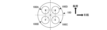
- FIG. 11 is a diagram illustrating the positional relationship of antennas when there are four antennas.
- the antenna unit 10 includes a first antenna 100A, a second antenna 100B, a third antenna 100C, and a fourth antenna 100D.
- the first antenna 100A and the second antenna 100B are arranged so that the base line connecting these antennas is parallel to the direction connecting the bow and the stern (the bow-stern direction).
- the third antenna 100C and the fourth antenna 100D are arranged so that the base line connecting these antennas is parallel to the bow-stern direction.
- the first antenna 100A and the fourth antenna 100D are arranged so that the base line connecting these antennas is parallel to the direction connecting the starboard and the port (a direction perpendicular to the bow-stern direction).
- the second antenna 100B and the third antenna 100C are arranged so that the base line connecting these antennas is parallel to the direction orthogonal to the bow-stern direction.
- any one of the first antenna 100A, the second antenna 100B, the third antenna 100C, and the fourth antenna 100D corresponds to the first GNSS antenna of the present invention, and two of the other antennas.
- the machine corresponds to the second GNSS antenna of the present invention.
- the antennas it is preferable to arrange the antennas so that the base line connecting two of the three or more antennas is parallel to the bow-stern direction. By using such an arrangement, calculation of the yaw angle ⁇ can be further facilitated.
Landscapes
- Engineering & Computer Science (AREA)
- Radar, Positioning & Navigation (AREA)
- Remote Sensing (AREA)
- Physics & Mathematics (AREA)
- General Physics & Mathematics (AREA)
- Computer Networks & Wireless Communication (AREA)
- Automation & Control Theory (AREA)
- Position Fixing By Use Of Radio Waves (AREA)
- Navigation (AREA)
Abstract
Description
11A,11B,11C:受信部
12:位相差算出部
13:演算部
20:慣性センサ
21:加速度センサ
22:角速度センサ
100:アンテナ部
100A,100B,100C,100D:アンテナ
131A,131B:誤差推定部
132A,132B:統合処理部
133A:GNSS速度算出部
134A:GNSS位置算出部 10, 10A, 10B:
Claims (16)
- GNSS信号を受信する第1、第2、第3のGNSSアンテナと、
前記第1のGNSSアンテナで受信したGNSS信号の搬送波位相を算出する第1のGNSS受信部と、
前記第2のGNSSアンテナで受信したGNSS信号の搬送波位相を算出する第2のGNSS受信部と、
前記第3のGNSSアンテナで受信したGNSS信号の搬送波位相を算出する第3のGNSS受信部と、
前記第1のGNSSアンテナ、前記第2のGNSSアンテナ、および前記第3のGNSSアンテナの内2つを選択して、マスターアンテナが少なくとも1でも異なる前記マスターアンテナとスレーブアンテナとの組合せを3つ以上決定し、組み合わせに用いられたGNSSアンテナの搬送波位相を用いて、組み合わせ毎にアンテナ間位相差を算出する位相差算出部と、
前記組み合わせ毎に算出された複数のアンテナ間位相差を用いて姿勢角を算出する演算部と、
を備える、状態算出装置。 First, second and third GNSS antennas for receiving GNSS signals;
A first GNSS receiver that calculates a carrier phase of a GNSS signal received by the first GNSS antenna;
A second GNSS receiver that calculates a carrier phase of a GNSS signal received by the second GNSS antenna;
A third GNSS receiver that calculates a carrier phase of a GNSS signal received by the third GNSS antenna;
By selecting two of the first GNSS antenna, the second GNSS antenna, and the third GNSS antenna, three or more combinations of the master antenna and the slave antenna that are different even if the master antenna is at least one A phase difference calculation unit that calculates a phase difference between antennas for each combination using the carrier phase of the GNSS antenna that is determined and used for the combination;
A calculation unit that calculates a posture angle using a plurality of inter-antenna phase differences calculated for each combination;
A state calculating device. - 請求項1に記載の状態算出装置であって、
前記演算部は、
前記複数のアンテナ間位相差からアンテナ間の幾何距離差を算出し、
前記幾何距離差から前記姿勢角を算出する、
状態算出装置。 The state calculation device according to claim 1,
The computing unit is
Calculate the geometric distance difference between the antennas from the phase difference between the plurality of antennas,
Calculating the posture angle from the geometric distance difference;
State calculation device. - 請求項2に記載の状態算出装置であって、
前記演算部は、誤差算出部と統合処理部を備え、
前記誤差算出部は、前記幾何距離差と統合処理部が算出した過去の姿勢角に基づく幾何距離差とを用いて、姿勢角の算出誤差を推定し、
前記統合処理部は、慣性センサが計測した角速度また加速度と前記姿勢角の算出誤差とを用いて姿勢角を算出する、
状態算出装置。 The state calculation device according to claim 2,
The calculation unit includes an error calculation unit and an integration processing unit,
The error calculation unit estimates a posture angle calculation error using the geometric distance difference and a geometric distance difference based on a past posture angle calculated by the integration processing unit,
The integrated processing unit calculates a posture angle using an angular velocity or acceleration measured by an inertial sensor and a calculation error of the posture angle;
State calculation device. - 請求項3に記載の状態算出装置であって、
前記誤差推定部は、
複数のGNSSアンテナで受信した前記GNSS信号から算出される位置と前記統合処理部が算出した過去の位置とを用いて前記位置の算出誤差を推定し、
前記複数のGNSSアンテナで受信した前記GNSS信号から算出される速度と前記統合処理部が算出した過去の速度とを用いて前記速度の算出誤差を推定し、
前記位置の算出誤差と前記速度の算出誤差を前記統合処理部に出力し、
前記統合処理部は、前記慣性センサが計測した角速度また加速度と、前記位置の算出誤差および前記速度の算出誤差を用いて、位置および速度を算出する、
状態算出装置。 The state calculation device according to claim 3,
The error estimator is
Estimating the position calculation error using the position calculated from the GNSS signals received by a plurality of GNSS antennas and the past position calculated by the integration processing unit;
Estimating a speed calculation error using a speed calculated from the GNSS signals received by the plurality of GNSS antennas and a past speed calculated by the integrated processing unit;
Outputting the position calculation error and the velocity calculation error to the integrated processing unit;
The integrated processing unit calculates a position and a velocity using an angular velocity or acceleration measured by the inertial sensor, the position calculation error, and the velocity calculation error.
State calculation device. - 請求項4に記載の状態算出装置であって、
前記第1のGNSS受信部で算出した前記第1のGNSSアンテナの位置、前記第2のGNSS受信部で算出した前記第2のGNSSアンテナの位置、および、前記第3のGNSS受信部で算出した前記第3のGNSSアンテナの位置を用いて特定点の位置を算出する位置算出部と、
前記第1のGNSS受信部で算出した前記第1のGNSSアンテナの速度、前記第2のGNSS受信部で算出した前記第2のGNSSアンテナの速度、および、前記第3のGNSS受信部で算出した前記第3のGNSSアンテナの速度を用いて特定点の速度を算出する速度算出部と、をさらに備え、
前記誤差推定部は、
前記特定点の位置と前記統合処理部が算出した前記特定点の過去の位置とを用いた前記位置の算出誤差、または、前記特定点の速度と前記統合処理部が算出した前記特定点の過去の速度とを用いた前記速度の算出誤差、を推定する、
状態算出装置。 The state calculation device according to claim 4,
The position of the first GNSS antenna calculated by the first GNSS receiver, the position of the second GNSS antenna calculated by the second GNSS receiver, and the position calculated by the third GNSS receiver A position calculation unit that calculates the position of the specific point using the position of the third GNSS antenna;
The speed of the first GNSS antenna calculated by the first GNSS receiver, the speed of the second GNSS antenna calculated by the second GNSS receiver, and the speed calculated by the third GNSS receiver A speed calculator that calculates the speed of the specific point using the speed of the third GNSS antenna;
The error estimator is
The position calculation error using the position of the specific point and the past position of the specific point calculated by the integration processing unit, or the speed of the specific point and the past of the specific point calculated by the integration processing unit An estimation error of the speed using the speed of
State calculation device. - 請求項1乃至請求項5のいずれかに記載の状態算出装置であって、
前記姿勢角はヨー角である、
状態算出装置。 The state calculation device according to any one of claims 1 to 5,
The posture angle is a yaw angle;
State calculation device. - 前記第1のGNSSアンテナで受信したGNSS信号の搬送波位相を算出する工程と、
前記第2のGNSSアンテナで受信したGNSS信号の搬送波位相を算出する工程と、
前記第3のGNSSアンテナで受信したGNSS信号の搬送波位相を算出する工程と、
前記第1のGNSSアンテナ、前記第2のGNSSアンテナ、および前記第3のGNSSアンテナの内2つを選択して、マスターアンテナが少なくとも1でも異なる前記マスターアンテナとスレーブアンテナとの組合せを3つ以上決定し、組み合わせに用いられたGNSSアンテナの搬送波位相を用いて、組み合わせ毎にアンテナ間位相差を算出する工程と、
前記組み合わせ毎に算出された複数のアンテナ間位相差を用いて姿勢角を算出する工程と、
を有する、状態算出方法。 Calculating a carrier phase of a GNSS signal received by the first GNSS antenna;
Calculating a carrier phase of a GNSS signal received by the second GNSS antenna;
Calculating a carrier phase of a GNSS signal received by the third GNSS antenna;
By selecting two of the first GNSS antenna, the second GNSS antenna, and the third GNSS antenna, three or more combinations of the master antenna and the slave antenna that are different even if the master antenna is at least one Determining and calculating the inter-antenna phase difference for each combination using the carrier phase of the GNSS antenna used for the combination;
Calculating a posture angle using a plurality of inter-antenna phase differences calculated for each combination;
A state calculation method. - 請求項7に記載の状態算出方法であって、
前記姿勢角を算出する工程は、
前記複数のアンテナ間位相差からアンテナ間の幾何距離差を算出し、
前記幾何距離差から前記姿勢角を算出する、
状態算出方法。 The state calculation method according to claim 7,
The step of calculating the posture angle includes:
Calculate the geometric distance difference between the antennas from the phase difference between the plurality of antennas,
Calculating the posture angle from the geometric distance difference;
State calculation method. - 請求項8に記載の状態算出方法であって、
前記姿勢角を算出する工程は、誤差算出工程と統合処理工程を有し、
前記誤差算出工程は、前記幾何距離差と統合処理工程で算出した過去の姿勢角に基づく幾何距離差とを用いて、姿勢角の算出誤差を推定し、
前記統合処理工程は、慣性センサが計測した角速度また加速度と前記姿勢角の算出誤差とを用いて姿勢角を算出する、
状態算出方法。 The state calculation method according to claim 8,
The step of calculating the posture angle includes an error calculation step and an integration processing step,
The error calculation step estimates a posture angle calculation error using the geometric distance difference and the geometric distance difference based on the past posture angle calculated in the integration processing step.
The integration processing step calculates the posture angle using the angular velocity or acceleration measured by the inertial sensor and the calculation error of the posture angle.
State calculation method. - 請求項9に記載の状態算出方法であって、
前記姿勢角とともに、位置および速度を算出し、
前記誤差推定工程は、
複数のGNSSアンテナで受信した前記GNSS信号から算出される位置と前記統合処理工程で算出した過去の位置とを用いて前記位置の算出誤差を推定し、
前記複数のGNSSアンテナで受信した前記GNSS信号から算出される速度と前記統合処理工程で算出した過去の速度とを用いて前記速度の算出誤差を推定し、
前記位置の算出誤差と前記速度の算出誤差を前記統合処理工程に出力し、
前記統合処理工程は、前記慣性センサが計測した角速度また加速度と、前記位置の算出誤差および前記速度の算出誤差を用いて、前記位置および前記速度を算出する、
状態算出方法。 The state calculation method according to claim 9,
Along with the attitude angle, calculate the position and speed,
The error estimation step includes
Estimating the position calculation error using the position calculated from the GNSS signals received by a plurality of GNSS antennas and the past position calculated in the integration processing step;
Estimating a speed calculation error using a speed calculated from the GNSS signals received by the plurality of GNSS antennas and a past speed calculated in the integration processing step;
Outputting the position calculation error and the speed calculation error to the integrated processing step;
The integration processing step calculates the position and the velocity using the angular velocity or acceleration measured by the inertial sensor, the position calculation error, and the velocity calculation error.
State calculation method. - 請求項10に記載の状態算出装置であって、
前記第1のGNSS受信部で算出した前記第1のGNSSアンテナの位置、前記第2のGNSS受信部で算出した前記第2のGNSSアンテナの位置、および、前記第3のGNSS受信部で算出した前記第3のGNSSアンテナの位置を用いて特定点の位置を算出する位置算出工程と、
前記第1のGNSS受信部で算出した前記第1のGNSSアンテナの速度、前記第2のGNSS受信部で算出した前記第2のGNSSアンテナの速度、および、前記第3のGNSS受信部で算出した前記第3のGNSSアンテナの速度を用いて特定点の速度を算出する速度算出工程と、をさらに有し、
前記姿勢角、位置および速度を算出する工程は、
前記特定点の位置と統合処理工程が算出した前記特定点の過去の位置とを用いた前記位置の算出誤差、または、前記特定点の速度と前記統合処理部が算出した前記特定点の過去の速度とを用いた前記速度の算出誤差、を推定する、
状態算出方法。 The state calculation device according to claim 10,
The position of the first GNSS antenna calculated by the first GNSS receiver, the position of the second GNSS antenna calculated by the second GNSS receiver, and the position calculated by the third GNSS receiver A position calculating step of calculating the position of the specific point using the position of the third GNSS antenna;
The speed of the first GNSS antenna calculated by the first GNSS receiver, the speed of the second GNSS antenna calculated by the second GNSS receiver, and the speed calculated by the third GNSS receiver A speed calculating step of calculating the speed of the specific point using the speed of the third GNSS antenna,
The step of calculating the posture angle, the position and the speed includes
The position calculation error using the position of the specific point and the past position of the specific point calculated by the integration processing step, or the speed of the specific point and the past of the specific point calculated by the integration processing unit An estimation error of the velocity using the velocity,
State calculation method. - GNSS信号を受信して、移動体の姿勢角を算出する処理を情報処理装置に実行させる状態算出プログラムであって、
前記情報処理装置は、
前記第1のGNSSアンテナで受信したGNSS信号の搬送波位相を算出する処理と、
前記第2のGNSSアンテナで受信したGNSS信号の搬送波位相を算出する処理と、
前記第3のGNSSアンテナで受信したGNSS信号の搬送波位相を算出する処理と、
前記第1のGNSSアンテナ、前記第2のGNSSアンテナ、および前記第3のGNSSアンテナの内2つを選択して、マスターアンテナが少なくとも1でも異なる前記マスターアンテナとスレーブアンテナとの組合せを3つ以上決定し、組み合わせに用いられたGNSSアンテナの搬送波位相を用いて、組み合わせ毎にアンテナ間位相差を算出する処理と、
前記組み合わせ毎に算出された複数のアンテナ間位相差を用いて姿勢角を算出する処理と、
を実行する、状態算出プログラム。 A state calculation program for receiving a GNSS signal and causing an information processing device to execute a process of calculating a posture angle of a moving object,
The information processing apparatus includes:
Processing for calculating the carrier phase of the GNSS signal received by the first GNSS antenna;
A process of calculating a carrier phase of a GNSS signal received by the second GNSS antenna;
Processing for calculating the carrier phase of the GNSS signal received by the third GNSS antenna;
By selecting two of the first GNSS antenna, the second GNSS antenna, and the third GNSS antenna, three or more combinations of the master antenna and the slave antenna that are different even if the master antenna is at least one A process of calculating the inter-antenna phase difference for each combination using the carrier phase of the GNSS antenna determined and used for the combination;
A process of calculating an attitude angle using a plurality of inter-antenna phase differences calculated for each combination;
A state calculation program that executes - 請求項12に記載の状態算出プログラムであって、
前記情報処理装置は、
前記姿勢角を算出する処理において、
前記複数のアンテナ間位相差からアンテナ間の幾何距離差を算出し、
前記幾何距離差から前記姿勢角を算出する、
状態算出プログラム。 A state calculation program according to claim 12,
The information processing apparatus includes:
In the process of calculating the posture angle,
Calculate the geometric distance difference between the antennas from the phase difference between the plurality of antennas,
Calculating the posture angle from the geometric distance difference;
State calculation program. - 請求項13に記載の状態算出プログラムであって、
前記情報処理装置は、
前記姿勢角を算出する処理に、誤差算出処理と統合処理を含み、
前記誤差算出処理において、前記幾何距離差と統合処理で算出した過去の姿勢角に基づく幾何距離差とを用いて、姿勢角の算出誤差を推定し、
前記統合処理において、慣性センサが計測した角速度また加速度と前記姿勢角の算出誤差とを用いて姿勢角を算出する、
状態算出プログラム。 The state calculation program according to claim 13,
The information processing apparatus includes:
The process for calculating the posture angle includes an error calculation process and an integration process,
In the error calculation process, using the geometric distance difference and the geometric distance difference based on the past attitude angle calculated in the integration process, the posture angle calculation error is estimated,
In the integration process, the attitude angle is calculated using the angular velocity or acceleration measured by the inertial sensor and the calculation error of the attitude angle.
State calculation program. - 請求項14に記載の状態算出プログラムであって、
前記情報処理装置は、
前記姿勢角とともに、位置および速度を算出し、
前記誤差推定において、
複数のGNSSアンテナで受信した前記GNSS信号から算出される位置と前記統合処理で算出した過去の位置とを用いて前記位置の算出誤差を推定し、
前記複数のGNSSアンテナで受信した前記GNSS信号から算出される速度と前記統合処理で算出した過去の速度とを用いて前記速度の算出誤差を推定し、
前記位置の算出誤差と前記速度の算出誤差を前記統合処理に出力し、
前記統合処理において、前記慣性センサが計測した角速度また加速度と、前記位置の算出誤差および前記速度の算出誤差を用いて、前記位置および前記速度を算出する、
状態算出プログラム。 The state calculation program according to claim 14,
The information processing apparatus includes:
Along with the attitude angle, calculate the position and speed,
In the error estimation,
Estimating the position calculation error using the position calculated from the GNSS signals received by a plurality of GNSS antennas and the past position calculated by the integration process;
Estimating a speed calculation error using a speed calculated from the GNSS signals received by the plurality of GNSS antennas and a past speed calculated by the integration process;
Outputting the position calculation error and the velocity calculation error to the integration process;
In the integration process, the position and the velocity are calculated using the angular velocity or acceleration measured by the inertial sensor, the position calculation error, and the velocity calculation error.
State calculation program. - 請求項15に記載の状態算出プログラムであって、
前記情報処理装置は、
前記第1のGNSS受信部で算出した前記第1のGNSSアンテナの位置、前記第2のGNSS受信部で算出した前記第2のGNSSアンテナの位置、および、前記第3のGNSS受信部で算出した前記第3のGNSSアンテナの位置を用いて特定点の位置を算出する位置算出処理と、
前記第1のGNSS受信部で算出した前記第1のGNSSアンテナの速度、前記第2のGNSS受信部で算出した前記第2のGNSSアンテナの速度、および、前記第3のGNSS受信部で算出した前記第3のGNSSアンテナの速度を用いて特定点の速度を算出する速度算出処理と、をさらに実行し、
前記姿勢角、位置および速度を算出する処理において、
前記特定点の位置と統合処理で算出した前記特定点の過去の位置とを用いた前記位置の算出誤差、または、前記特定点の速度と前記統合処理で算出した前記特定点の過去の速度とを用いた前記速度の算出誤差、を推定する、
状態算出プログラム。 The state calculation program according to claim 15,
The information processing apparatus includes:
The position of the first GNSS antenna calculated by the first GNSS receiver, the position of the second GNSS antenna calculated by the second GNSS receiver, and the position calculated by the third GNSS receiver A position calculation process for calculating the position of the specific point using the position of the third GNSS antenna;
The speed of the first GNSS antenna calculated by the first GNSS receiver, the speed of the second GNSS antenna calculated by the second GNSS receiver, and the speed calculated by the third GNSS receiver Further executing a speed calculation process for calculating the speed of the specific point using the speed of the third GNSS antenna,
In the process of calculating the posture angle, position and speed,
The position calculation error using the position of the specific point and the past position of the specific point calculated by the integration process, or the speed of the specific point and the past speed of the specific point calculated by the integration process Estimating the speed calculation error using
State calculation program.
Priority Applications (4)
| Application Number | Priority Date | Filing Date | Title |
|---|---|---|---|
| US15/540,022 US10197681B2 (en) | 2014-12-26 | 2015-11-26 | State calculating device, method of calculating state, and state calculating program |
| CN201580069895.7A CN107110978B (en) | 2014-12-26 | 2015-11-26 | State calculation device, state calculation method, and storage medium |
| EP15872602.6A EP3239741A4 (en) | 2014-12-26 | 2015-11-26 | State calculating apparatus, state calculating method and state calculating program |
| JP2016566054A JP6360199B2 (en) | 2014-12-26 | 2015-11-26 | State calculation device, state calculation method, and state calculation program |
Applications Claiming Priority (2)
| Application Number | Priority Date | Filing Date | Title |
|---|---|---|---|
| JP2014-264587 | 2014-12-26 | ||
| JP2014264587 | 2014-12-26 |
Publications (1)
| Publication Number | Publication Date |
|---|---|
| WO2016104033A1 true WO2016104033A1 (en) | 2016-06-30 |
Family
ID=56150065
Family Applications (1)
| Application Number | Title | Priority Date | Filing Date |
|---|---|---|---|
| PCT/JP2015/083154 WO2016104033A1 (en) | 2014-12-26 | 2015-11-26 | State calculating apparatus, state calculating method and state calculating program |
Country Status (5)
| Country | Link |
|---|---|
| US (1) | US10197681B2 (en) |
| EP (1) | EP3239741A4 (en) |
| JP (1) | JP6360199B2 (en) |
| CN (1) | CN107110978B (en) |
| WO (1) | WO2016104033A1 (en) |
Cited By (4)
| Publication number | Priority date | Publication date | Assignee | Title |
|---|---|---|---|---|
| WO2020008706A1 (en) * | 2018-07-06 | 2020-01-09 | Terra Drone株式会社 | Information collection device and unmanned aircraft equipped with same |
| JP2020056701A (en) * | 2018-10-03 | 2020-04-09 | 古野電気株式会社 | Navigation device, flight assisting information generation method, and flight assisting information generation program |
| JPWO2021020048A1 (en) * | 2019-08-01 | 2021-02-04 | ||
| CN112840235A (en) * | 2018-09-21 | 2021-05-25 | 古野电气株式会社 | Navigation device, method and program for generating navigation support information |
Families Citing this family (10)
| Publication number | Priority date | Publication date | Assignee | Title |
|---|---|---|---|---|
| GB2546241A (en) * | 2015-12-07 | 2017-07-19 | Atlantic Inertial Systems Ltd | Inertial navigation system |
| CN107797131A (en) * | 2017-09-25 | 2018-03-13 | 华南理工大学 | Unmanned boat data fusion attitude measurement method based on gps carrier phase posture |
| EP3734330A4 (en) * | 2017-12-01 | 2021-11-03 | Furuno Electric Co., Ltd. | Oscillation observation device, oscillation observation method, and oscillation observation program |
| US11609346B2 (en) * | 2018-05-29 | 2023-03-21 | Topcon Positioning Systems, Inc. | GNSS-based attitude determination algorithm and triple-antenna GNSS receiver for its implementation |
| CN109116396B (en) * | 2018-08-09 | 2022-10-21 | 大连理工大学 | Multi-antenna GNSS differential positioning method |
| DE102019207844A1 (en) * | 2019-05-28 | 2020-12-03 | Siemens Mobility GmbH | Device and method for determining the speed of a rail vehicle |
| CN112444836B (en) * | 2019-08-27 | 2022-12-02 | 千寻位置网络有限公司 | Satellite orientation method and device based on four antennas and positioning system |
| CN112099070B (en) * | 2020-08-24 | 2024-08-27 | 泰斗微电子科技有限公司 | Direction finding method, direction finding device, direction finding system and reference station |
| CN115096303B (en) * | 2022-08-25 | 2022-11-22 | 中南大学 | GNSS multi-antenna and INS tightly-combined positioning and attitude determination method and equipment |
| US20240219576A1 (en) * | 2022-12-30 | 2024-07-04 | Trimble Inc. | Gnss location determination using a virtual antenna |
Citations (5)
| Publication number | Priority date | Publication date | Assignee | Title |
|---|---|---|---|---|
| JP2002040124A (en) * | 2000-07-24 | 2002-02-06 | Furuno Electric Co Ltd | Measuring device for carrier phase relative position |
| JP2002054946A (en) * | 2000-06-01 | 2002-02-20 | Furuno Electric Co Ltd | Attitude sensor of object and integer bias re- determination method |
| JP2003232845A (en) * | 2002-02-12 | 2003-08-22 | Furuno Electric Co Ltd | Detection device of azimuth and attitude of moving body |
| JP2006126181A (en) * | 2004-10-01 | 2006-05-18 | Mitsubishi Electric Corp | Mobile attitude-detecting apparatus |
| JP2006153816A (en) * | 2004-12-01 | 2006-06-15 | Furuno Electric Co Ltd | Apparatus for detecting azimuth and attitude of object |
Family Cites Families (17)
| Publication number | Priority date | Publication date | Assignee | Title |
|---|---|---|---|---|
| US5021792A (en) * | 1990-01-12 | 1991-06-04 | Rockwell International Corporation | System for determining direction or attitude using GPS satellite signals |
| US5657025A (en) * | 1995-08-07 | 1997-08-12 | Litton Systems, Inc. | Integrated GPS/inertial navigation apparatus providing improved heading estimates |
| US6052647A (en) * | 1997-06-20 | 2000-04-18 | Stanford University | Method and system for automatic control of vehicles based on carrier phase differential GPS |
| AU775676B2 (en) | 2000-06-01 | 2004-08-12 | Furuno Electric Company, Limited | System for determining the heading and/or attitude of a body |
| US8265826B2 (en) * | 2003-03-20 | 2012-09-11 | Hemisphere GPS, LLC | Combined GNSS gyroscope control system and method |
| US8140223B2 (en) * | 2003-03-20 | 2012-03-20 | Hemisphere Gps Llc | Multiple-antenna GNSS control system and method |
| US9002565B2 (en) * | 2003-03-20 | 2015-04-07 | Agjunction Llc | GNSS and optical guidance and machine control |
| US8594879B2 (en) * | 2003-03-20 | 2013-11-26 | Agjunction Llc | GNSS guidance and machine control |
| US8639416B2 (en) * | 2003-03-20 | 2014-01-28 | Agjunction Llc | GNSS guidance and machine control |
| US8583315B2 (en) * | 2004-03-19 | 2013-11-12 | Agjunction Llc | Multi-antenna GNSS control system and method |
| US7292185B2 (en) * | 2005-10-04 | 2007-11-06 | Csi Wireless Inc. | Attitude determination exploiting geometry constraints |
| US8130142B2 (en) * | 2009-09-21 | 2012-03-06 | Appareo Systems, Llc | GNSS ultra-short baseline heading determination system and method |
| US8638257B2 (en) * | 2009-10-15 | 2014-01-28 | Novatel, Inc. | Ultra short baseline GNSS receiver |
| FR2971654B1 (en) * | 2011-02-10 | 2013-03-15 | Thales Sa | WIDEBAND RECEIVING DEVICE BY AUTOTRANSPOSITION AND APPLICATION TO THE DETECTION AND CHARACTERIZATION OF RADIO EMISSIONS |
| CN102508275B (en) * | 2011-10-28 | 2013-06-19 | 北京航空航天大学 | Multiple-antenna GPS(Global Positioning System)/GF-INS (Gyroscope-Free-Inertial Navigation System) depth combination attitude determining method |
| CN102636149B (en) * | 2012-05-04 | 2014-10-08 | 东南大学 | Combined measurement device and method for dynamic deformation of flexible bodies |
| US10677934B2 (en) * | 2016-06-09 | 2020-06-09 | Commscope Technologies Llc | Rapid azimuth determination in a GPS interferometer |
-
2015
- 2015-11-26 EP EP15872602.6A patent/EP3239741A4/en not_active Withdrawn
- 2015-11-26 CN CN201580069895.7A patent/CN107110978B/en active Active
- 2015-11-26 JP JP2016566054A patent/JP6360199B2/en active Active
- 2015-11-26 WO PCT/JP2015/083154 patent/WO2016104033A1/en active Application Filing
- 2015-11-26 US US15/540,022 patent/US10197681B2/en active Active
Patent Citations (5)
| Publication number | Priority date | Publication date | Assignee | Title |
|---|---|---|---|---|
| JP2002054946A (en) * | 2000-06-01 | 2002-02-20 | Furuno Electric Co Ltd | Attitude sensor of object and integer bias re- determination method |
| JP2002040124A (en) * | 2000-07-24 | 2002-02-06 | Furuno Electric Co Ltd | Measuring device for carrier phase relative position |
| JP2003232845A (en) * | 2002-02-12 | 2003-08-22 | Furuno Electric Co Ltd | Detection device of azimuth and attitude of moving body |
| JP2006126181A (en) * | 2004-10-01 | 2006-05-18 | Mitsubishi Electric Corp | Mobile attitude-detecting apparatus |
| JP2006153816A (en) * | 2004-12-01 | 2006-06-15 | Furuno Electric Co Ltd | Apparatus for detecting azimuth and attitude of object |
Non-Patent Citations (1)
| Title |
|---|
| See also references of EP3239741A4 * |
Cited By (8)
| Publication number | Priority date | Publication date | Assignee | Title |
|---|---|---|---|---|
| WO2020008706A1 (en) * | 2018-07-06 | 2020-01-09 | Terra Drone株式会社 | Information collection device and unmanned aircraft equipped with same |
| CN112840235A (en) * | 2018-09-21 | 2021-05-25 | 古野电气株式会社 | Navigation device, method and program for generating navigation support information |
| JP2020056701A (en) * | 2018-10-03 | 2020-04-09 | 古野電気株式会社 | Navigation device, flight assisting information generation method, and flight assisting information generation program |
| CN110988950A (en) * | 2018-10-03 | 2020-04-10 | 古野电气株式会社 | Navigation device, method for generating navigation assistance information, and storage medium |
| JP7223542B2 (en) | 2018-10-03 | 2023-02-16 | 古野電気株式会社 | Navigation device, method for generating navigation support information, and program for generating navigation support information |
| JPWO2021020048A1 (en) * | 2019-08-01 | 2021-02-04 | ||
| WO2021020048A1 (en) * | 2019-08-01 | 2021-02-04 | 古野電気株式会社 | Attitude measurement device, attitude measurement method, and attitude measurement program |
| JP7449938B2 (en) | 2019-08-01 | 2024-03-14 | 古野電気株式会社 | Posture measurement device, posture measurement method, and posture measurement program |
Also Published As
| Publication number | Publication date |
|---|---|
| JP6360199B2 (en) | 2018-07-18 |
| US20170350988A1 (en) | 2017-12-07 |
| EP3239741A1 (en) | 2017-11-01 |
| EP3239741A4 (en) | 2018-10-10 |
| CN107110978B (en) | 2021-02-02 |
| JPWO2016104033A1 (en) | 2017-09-21 |
| CN107110978A (en) | 2017-08-29 |
| US10197681B2 (en) | 2019-02-05 |
Similar Documents
| Publication | Publication Date | Title |
|---|---|---|
| JP6360199B2 (en) | State calculation device, state calculation method, and state calculation program | |
| US9342075B2 (en) | Apparatus, method and computer readable media for calculating status, and movable body | |
| US10514469B2 (en) | Attitude angle calculating device, method of calculating attitude angle, and attitude angle calculating program | |
| JP2008298443A (en) | Multipath detection device, positioning device, attitude azimuth orientation device, multipath detection method, and multipath detection program | |
| WO2017090359A1 (en) | Attitude angle calculation device and attitude angle calculation method | |
| Dai et al. | Heading-determination using the sensor-fusion based maritime PNT Unit | |
| Hayward et al. | Single baseline GPS based attitude heading reference system (AHRS) for aircraft applications | |
| CN107092027B (en) | The method and apparatus of attitude angle is calculated using signal receiver | |
| Sollie et al. | Pose estimation of UAVs based on INS aided by two independent low-cost GNSS receivers | |
| WO2018135187A1 (en) | Azimuth angle calculator, azimuth angle calculation method, and azimuth angle calculation program | |
| JP2018059856A (en) | Attitude angle calculation device and attitude angle calculation method | |
| JP2009145283A (en) | Positioning device | |
| JP2007071868A (en) | System and method of carrier phase relative positioning | |
| JP6732926B2 (en) | Azimuth calculation device, azimuth calculation method, and azimuth calculation program | |
| RU2422844C2 (en) | Method of defining angular orientation of object | |
| JP4417812B2 (en) | Ship attitude angle measuring device | |
| WO2017141614A1 (en) | Tsunami observation device, tsunami observation system, and tsunami observation method | |
| WO2024180582A1 (en) | Position/attitude calibration device, position/attitude calibration method, and position/attitude calibration program | |
| Nakamura et al. | Robust Attitude Determination Using GNSS Multi Baseline Carrier Phase and IMU Sensor Fusion | |
| JP6199679B2 (en) | Posture detection apparatus, moving body including the same, and posture detection method | |
| Knedlik et al. | GPS/INS integration for footprint chasing in bistatic SAR experiments | |
| RU2241208C1 (en) | Moving object route detector | |
| Kao et al. | Carrier Phase Indoor Positioning Using Pseudolites And INS |
Legal Events
| Date | Code | Title | Description |
|---|---|---|---|
| 121 | Ep: the epo has been informed by wipo that ep was designated in this application |
Ref document number: 15872602 Country of ref document: EP Kind code of ref document: A1 |
|
| ENP | Entry into the national phase |
Ref document number: 2016566054 Country of ref document: JP Kind code of ref document: A |
|
| NENP | Non-entry into the national phase |
Ref country code: DE |
|
| WWE | Wipo information: entry into national phase |
Ref document number: 15540022 Country of ref document: US |
|
| REEP | Request for entry into the european phase |
Ref document number: 2015872602 Country of ref document: EP |