WO2016103770A1 - Exercise assisting device - Google Patents
Exercise assisting device Download PDFInfo
- Publication number
- WO2016103770A1 WO2016103770A1 PCT/JP2015/069483 JP2015069483W WO2016103770A1 WO 2016103770 A1 WO2016103770 A1 WO 2016103770A1 JP 2015069483 W JP2015069483 W JP 2015069483W WO 2016103770 A1 WO2016103770 A1 WO 2016103770A1
- Authority
- WO
- WIPO (PCT)
- Prior art keywords
- grip
- weight
- gripping
- person
- grip member
- Prior art date
Links
Images


Classifications
-
- A—HUMAN NECESSITIES
- A63—SPORTS; GAMES; AMUSEMENTS
- A63B—APPARATUS FOR PHYSICAL TRAINING, GYMNASTICS, SWIMMING, CLIMBING, OR FENCING; BALL GAMES; TRAINING EQUIPMENT
- A63B21/00—Exercising apparatus for developing or strengthening the muscles or joints of the body by working against a counterforce, with or without measuring devices
- A63B21/06—User-manipulated weights
- A63B21/072—Dumb-bells, bar-bells or the like, e.g. weight discs having an integral peripheral handle
- A63B21/0726—Dumb bells, i.e. with a central bar to be held by a single hand, and with weights at the ends
-
- A—HUMAN NECESSITIES
- A63—SPORTS; GAMES; AMUSEMENTS
- A63B—APPARATUS FOR PHYSICAL TRAINING, GYMNASTICS, SWIMMING, CLIMBING, OR FENCING; BALL GAMES; TRAINING EQUIPMENT
- A63B69/00—Training appliances or apparatus for special sports
- A63B69/0028—Training appliances or apparatus for special sports for running, jogging or speed-walking
-
- A—HUMAN NECESSITIES
- A63—SPORTS; GAMES; AMUSEMENTS
- A63B—APPARATUS FOR PHYSICAL TRAINING, GYMNASTICS, SWIMMING, CLIMBING, OR FENCING; BALL GAMES; TRAINING EQUIPMENT
- A63B21/00—Exercising apparatus for developing or strengthening the muscles or joints of the body by working against a counterforce, with or without measuring devices
- A63B21/06—User-manipulated weights
- A63B21/0601—Special physical structures of used masses
- A63B21/0604—Solid masses, e.g. concrete
-
- A—HUMAN NECESSITIES
- A63—SPORTS; GAMES; AMUSEMENTS
- A63B—APPARATUS FOR PHYSICAL TRAINING, GYMNASTICS, SWIMMING, CLIMBING, OR FENCING; BALL GAMES; TRAINING EQUIPMENT
- A63B23/00—Exercising apparatus specially adapted for particular parts of the body
- A63B23/035—Exercising apparatus specially adapted for particular parts of the body for limbs, i.e. upper or lower limbs, e.g. simultaneously
- A63B23/12—Exercising apparatus specially adapted for particular parts of the body for limbs, i.e. upper or lower limbs, e.g. simultaneously for upper limbs or related muscles, e.g. chest, upper back or shoulder muscles
- A63B23/16—Exercising apparatus specially adapted for particular parts of the body for limbs, i.e. upper or lower limbs, e.g. simultaneously for upper limbs or related muscles, e.g. chest, upper back or shoulder muscles for hands or fingers
-
- A—HUMAN NECESSITIES
- A63—SPORTS; GAMES; AMUSEMENTS
- A63B—APPARATUS FOR PHYSICAL TRAINING, GYMNASTICS, SWIMMING, CLIMBING, OR FENCING; BALL GAMES; TRAINING EQUIPMENT
- A63B21/00—Exercising apparatus for developing or strengthening the muscles or joints of the body by working against a counterforce, with or without measuring devices
- A63B21/40—Interfaces with the user related to strength training; Details thereof
- A63B21/4001—Arrangements for attaching the exercising apparatus to the user's body, e.g. belts, shoes or gloves specially adapted therefor
- A63B21/4017—Arrangements for attaching the exercising apparatus to the user's body, e.g. belts, shoes or gloves specially adapted therefor to the upper limbs
- A63B21/4019—Arrangements for attaching the exercising apparatus to the user's body, e.g. belts, shoes or gloves specially adapted therefor to the upper limbs to the hand
-
- A—HUMAN NECESSITIES
- A63—SPORTS; GAMES; AMUSEMENTS
- A63B—APPARATUS FOR PHYSICAL TRAINING, GYMNASTICS, SWIMMING, CLIMBING, OR FENCING; BALL GAMES; TRAINING EQUIPMENT
- A63B21/00—Exercising apparatus for developing or strengthening the muscles or joints of the body by working against a counterforce, with or without measuring devices
- A63B21/40—Interfaces with the user related to strength training; Details thereof
- A63B21/4027—Specific exercise interfaces
- A63B21/4039—Specific exercise interfaces contoured to fit to specific body parts, e.g. back, knee or neck support
Definitions
- the present invention relates to an exercise assisting device used for jogging or walking.
- Patent Document 1 As an exercise assisting instrument used for jogging (running), walking (walking), etc., one having a baton-shaped grip having irregularities on the surface is known (for example, see Patent Document 1).
- the grip described in Patent Document 1 is formed in a cylindrical shape that becomes thinner from one end to the other end.
- the grip described in Patent Document 1 has irregularities that match the shape of five fingers when grasping.
- the grip described in Patent Document 1 is said to be able to run with a better form by running while holding a grip having unevenness, thereby reducing the balance of the balance of the body.
- An object of the present invention is to provide an exercise assisting device that can correctly swing an arm during running and walking and can stabilize the way of swinging the arm.
- the present invention relates to an exercise assisting device including a gripping member extending in a cylindrical shape or a columnar shape that can be gripped by a hand, and the gripping member has a concave portion in which only a portion where a middle finger is disposed when gripped by a hand.
- the exercise assisting device when gripping the grip member in front of a person with the grip member in a standing state, the front of the grip member corresponds to the front of the person, and the rear of the grip member corresponds to the back of the person, It is preferable that the exercise assisting device further includes a first weight member disposed at a lower part on the rear side of the grip member.
- the exercise assisting device when gripping the grip member in front of a person with the grip member in a standing state, the front of the grip member corresponds to the front of the person, and the rear of the grip member corresponds to the back of the person, It is preferable that the exercise assisting device further includes a second weight member disposed on the rear side of the grip member and extending in a longitudinal direction of the grip member.
- the grip member when the grip member is gripped in front of a person with the grip member standing, the front of the grip member corresponds to the front of the person, the rear of the grip member corresponds to the rear of the person, and the grip
- the outer side of the member corresponds to the outer side of either one of the left and right directions of the person, and the exercise assisting device is disposed on one outer side of the grip member, and the grip member It is preferable to further include a third weight member extending in the longitudinal direction.
- a projecting portion disposed between the ring finger and the little finger.
- the exercise assisting device when gripping the grip member in front of a person with the grip member in a standing state, the front of the grip member corresponds to the front of the person, and the rear of the grip member corresponds to the back of the person, It is preferable that the exercise assisting device further includes a holder that is disposed on the rear side of the gripping member and covers the thumb in a state of standing upward.
- the exercise assisting device further includes a fourth weight member disposed on the rear side of the holder.
- an exercise assisting device that can correctly swing an arm during running or walking and can stabilize the manner of swinging the arm.
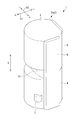
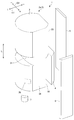
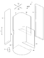
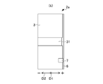
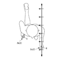
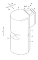
- FIG. 1 It is a perspective view which shows the grip body 2a for left hands of the exercise assistance instrument 1 of 1st Embodiment of this invention. It is a disassembled perspective view of the grip body 2a. It is the disassembled perspective view which looked at the grip body 2a from the angle different from FIG. It is the figure which looked at the grip body 2a shown in FIG. 1 from the minus side (inward side of the grip body 2a for left hands) of the 2nd direction D2 (left-right direction). It is the figure which looked at the grip body 2a shown in FIG. 1 from the plus side (front side) of the 1st direction D1 (front-back direction). It is the figure which looked at the grip body 2a shown in FIG.
- FIG. 1 is a perspective view showing a left hand grip body 2a of an exercise assistance device 1 according to a first embodiment of the present invention.
- FIG. 2 is an exploded perspective view of the grip body 2a.
- FIG. 3 is an exploded perspective view of the grip body 2a viewed from an angle different from that in FIG. 4A is a view of the grip body 2a shown in FIG. 1 as viewed from the minus side in the second direction D2 (left-right direction) (inward side of the grip body 2a for the left hand), and
- FIG. 4B is a grip body shown in FIG.
- FIG. 4C is a view of the grip body 2a shown in FIG.
- FIG. 4D is a view of the grip body 2a shown in FIG. 1 viewed from the minus side (rear side) of the first direction D1 (front-rear direction).
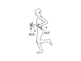
- the exercise assisting apparatus 1 is used for running such as short-distance running or jogging or walking such as walking.
- the exercise assisting device 1 includes a pair of left and right grip bodies 2.
- the pair of grip bodies 2 is composed of a pair for left hand and right hand.
- the left hand grip body 2a and the right hand grip body 2b are simultaneously used.
- the grip body 2a shown in FIGS. 1 to 4D in the present embodiment is described for the left hand.
- the constituent members constituting the left-hand grip body 2a described below are symmetrical to the constituent members constituting the right-hand grip body 2b. Note that the grip body 2b for the right hand is illustrated in FIGS. 8A to 11B, but is not illustrated in FIGS.
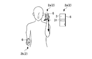
- the left hand grip body 2a includes a left hand grip member 3 (grip member), a first weight member 4, a second weight member 5, and a third weight member 6. And a protruding member 7 (protruding portion).
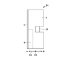
- the direction in which the gripping member 3 extends is referred to as the longitudinal direction L.
- the first direction D1 and the second direction D2 of the grip body 2a are directions orthogonal to each other.
- the first direction D1 and the second direction D2 are each orthogonal to the longitudinal direction L.
- the first direction D1 is the front-rear direction of the gripping member 3, and is viewed from the person who grips the gripping member 3 when the gripping member 3 is gripped in front of the person with the gripping member 3 standing (see FIG. 5).
- the direction corresponds to the front-rear direction of the person in the case.
- the plus (+) side corresponds to the front side of the person
- the minus ( ⁇ ) side corresponds to the back side of the person.
- the second direction D2 is the left-right direction of the grip member 3, and is viewed from the person who grips the grip member 3 when the grip member 3 is gripped in front of the person with the grip member 3 standing (see FIG. 5).
- the direction corresponds to the left and right direction of the person in the case.
- the plus (+) side of the second direction D2 is one outer side of the grip member 3, and corresponds to one outer side in the left-right direction of the person.
- the plus (+) side (outward side) of the second direction D2 (left and right direction) is the left side with respect to the left hand grip member 3 when the left hand grip member 3 is gripped. is there.
- the plus (+) side (outward side) of the second direction D2 is the right side with respect to the right hand grip member 3 when the right hand grip member 3 is gripped.
- the minus ( ⁇ ) side of the second direction D2 is one inward side of the grip member 3, and corresponds to one inward side in the left-right direction of the person.
- the minus ( ⁇ ) side (inward side) of the second direction D2 (left and right direction) is the right side with respect to the left hand grip member 3 when the left hand grip member 3 is gripped. is there.
- the minus ( ⁇ ) side (inward side) of the second direction D2 (left and right direction) is the left side with respect to the right hand grip member 3 when the right hand grip member 3 is gripped. Since the grip body 2a is shaken while being held by a person, the orientation of the grip body 2a when viewed from the person holding the grip member 3 changes depending on the position of the grip body 2a.
- the gripping member 3 extends in the longitudinal direction L as shown in FIGS. 1 to 4D.
- the grip member 3 is formed in a cylindrical shape or a column shape that can be gripped with the left hand.
- the grip member 3 is substantially cylindrical or substantially columnar.
- the grip member 3 is not limited to a substantially cylindrical shape or a substantially columnar shape, and may be a polygonal cylinder shape or a polygonal column shape, for example.
- the thickness of the gripping member 3 is a thickness that allows the gripping member 3 to be gripped in a state where the finger is extended along the circumferential direction of the gripping member 3.
- the material of the grip member 3 is preferably a light material, and is made of, for example, a plastic material or a cardboard material. Moreover, the material of the grip member 3 is preferably a material that can be easily adapted to the hand.
- the grip member 3 is provided with a concave groove 31 (concave portion).
- the concave groove 31 is formed in a groove shape extending in the second direction D2 (left-right direction) on the surface on the plus side (front side) of the first direction D1 (front-rear direction) at a substantially central portion in the longitudinal direction L.
- the concave groove 31 is a portion where only the portion where the middle finger is disposed in the grip member 3 is recessed when the grip member 3 is gripped by hand.
- the width of the groove of the concave groove 31 is a width in which the middle finger can be arranged.
- the gripping member 3 includes a first weight attachment portion 32, a second weight attachment portion 33, a third weight attachment portion 34, and a protrusion attachment portion 35.
- the first weight attachment portion 32 and the second weight attachment portion 33 are formed in a planar shape on the minus side (rear side) side portion of the grip member 3 in the first direction D1 (front-rear direction).
- the third weight attachment portion 34 is formed in a planar shape on the plus side (outward side) side portion of the grip member 3 in the second direction D2 (left-right direction).
- a first weight member 4 to be described later is attached to the first weight attachment portion 32.
- the first weight attachment portion 32 is a flat surface on the minus side (rear side) of the grip member 3 in the first direction D1 (front-rear direction).
- the first weight attachment portion 32 is configured by a substantially half plane on the lower side from the approximate center in the longitudinal direction L of the grip member 3.
- the first weight attachment portion 32 is a plane that is one step lower than a second weight attachment portion 33 described later.
- the second weight attachment portion 33 is a flat surface on the minus side (rear side) of the grip member 3 in the first direction D1 (front-rear direction).
- the second weight attachment portion 33 is configured by a substantially half plane on the upper side from the approximate center in the longitudinal direction L of the grip member 3.
- the second weight attachment portion 33 is a flat surface that is one step higher than the first weight attachment portion 32.
- the third weight member 6 to be described later is attached to the third weight attachment portion 34.
- the third weight attachment portion 34 is a plane on the plus side (outward side) of the grip member 3 in the second direction D2 (left-right direction).
- the third weight attachment portion 34 is a plane extending over the entire area in the longitudinal direction L.
- the protrusion attachment part 35 is attached with a protrusion member 7 to be described later.
- the protrusion member 7 attached to the protrusion attachment portion 35 is disposed between the ring finger and the little finger when gripping the grip member 3.
- the protrusion attachment portion 35 is provided near the third weight attachment portion 34 on the lower side on the outer peripheral surface of the grip member 3 on the plus side (front side) in the first direction D ⁇ b> 1 (front-rear direction). A curved surface within a predetermined range.
- the first weight member 4, the second weight member 5, and the third weight member 6 are weights for adjusting the balance of the grip member 3.
- the first weight member 4, the second weight member 5, and the third weight member 6 are made of a material having a specific gravity greater than that of the grip member 3, for example, a metal.
- the first weight member 4, the second weight member 5, and the third weight member 6 are configured to be detachable from the grip member 3, as shown in FIGS.
- the first weight member 4, the second weight member 5, and the third weight member 6 can each be set by selecting a weight.
- the first weight member 4, the second weight member 5, and the third weight member 6 can be set by appropriately selecting the weight and combination.
- the first weight member 4 is attached to the first weight attachment portion 32 of the grip member 3.
- the first weight member 4 is attached to a substantially half on the lower side in the plane of the first weight attachment portion 32 on the minus side (rear side) of the grip member 3 in the first direction D1 (front-rear direction).
- the first weight member 4 extends in the longitudinal direction L of the gripping member 3.
- the first weight member 4 is a plate member parallel to the longitudinal direction L and the second direction D2 (left-right direction).
- the second weight member 5 After the first weight member 4 is attached to the gripping member 3, the second weight member 5 includes a negative side (rear side) surface of the first weight member 4 in the first direction D1 (front-rear direction), and a second weight. It is mounted across the plane of the mounting portion 33. The second weight member 5 extends over the entire length direction L of the grip member 3. The second weight member 5 is a plate member parallel to the longitudinal direction L and the second direction D2 (left-right direction).
- the third weight member 6 is attached to the third weight attachment portion 34 of the gripping member 3.
- the third weight member 6 is attached to the third weight attachment portion 34 on the plus side (outward side) of the grip member 3 in the second direction D2 (left-right direction).
- the third weight member 6 extends in the longitudinal direction L of the gripping member 3.
- the third weight member 6 is a plate member parallel to the longitudinal direction L and the first direction D1 (front-rear direction).
- the protruding member 7 is configured to be detachable from the gripping member 3.
- the protrusion member 7 has a fitting convex part (not shown), and the grip member 3 has a fitting concave part (not shown).
- the protruding member 7 can be attached to and detached from the gripping member 3.
- the protrusion member 7 is attached to the protrusion attachment portion 35.
- the protruding member 7 protrudes outward from the outer surface of the gripping member 3.
- the protruding member 7 is disposed between the ring finger and the little finger when the gripping member 3 is gripped.
- the protruding member 7 is a third weight member 6 below the plus side (outside) of the second direction D2 (left-right direction) on the plus side (front side) of the first direction D1 (front-back direction) of the grip member 3. It is arranged on the projection mounting part 35 on the side.
- the protruding member 7 is mounted when the exercise assisting device 1 is used in a horizontal operation mode described later, and is used as an optional member.
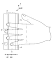
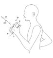
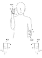
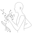
- FIG. 5 is a view for explaining how to grip the grip body 2 a and is a view for explaining a state in which the middle finger is arranged in the concave groove 31 of the grip member 3.
- 6A and 6B are diagrams for explaining how to grip the grip body 2a, and are diagrams illustrating a state in which the thumb is disposed on the grip body 2a.
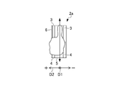
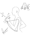
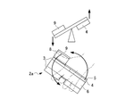
- FIG. 7 is a view for explaining the operation of the first weight member 4.
- 8A to 8C are views for explaining the operation of the second weight member 5.
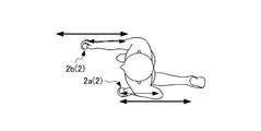
- 9A and 9B are views for explaining the operation of the third weight member 6.
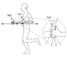
- FIG. 10 is a view for explaining an effect produced by providing the first weight member 4 and the third weight member 6 together.
- 11A and 11B are diagrams for explaining the operation of the protruding member 7.
- the grip body 2 of the exercise assisting device 1 When the grip body 2 of the exercise assisting device 1 is gripped, the middle finger is disposed in the concave groove 31 of the gripping member 3 as shown in FIGS. 5 to 6B. At the same time, as shown in FIG. 6A and FIG. 6B, the second weight member 5 is applied to the second weight member 5 so that the portion from the base of the thumb (finger ball) to the tip portion is applied to the second weight member 5 with the thumb standing. Touch the thumb. In this state, the grip body 2 is gripped.
- the gripping body 7 is attached to the gripping member 3 as an optional member, and the protruding member 7 is disposed between the ring finger and the little finger. 2 (see FIGS. 11A and 11B).
- the arm When running such as jogging or walking such as walking, the arm is swung in the front-rear direction while holding the grip body 2 with both hands. Thereby, the grip body 2 held by both hands is swung in the front-rear direction.
- the main characteristic structure of the exercise assisting device 1 will be described in terms of the effect on how to swing the arm when running or walking.
- the first running state is a state in which an elbow is pulled and a person walks or walks while holding a fist without using any equipment.
- the fist since the fist is firmly held, the fist is stable and the arm can be easily moved up and down.
- force is applied to the fist and the side is too tight, so that it is difficult to pull the elbow greatly behind. For this reason, it is difficult to pull the arm backward, and the running tends to be unstable.
- the second running state is a state in which a user runs and walks with only the index finger being folded without using any equipment and with fingers other than the index finger opened.
- the palm of the hand (lower part of the palm) faces down and the sides are open. For this reason, the arms are swung in the front-rear direction with the sides open, and thus traveling tends to become unstable.
- the third running state is a state in which a device is used to fold only by putting power on only the little finger or ring finger without using any instrument, and in a state where other fingers other than the folded finger are opened. .
- the palm of the hand (lower part of the palm) faces up and the sides are open. For this reason, the arms are swung in the front-rear direction with the sides open, and thus traveling tends to become unstable.
- the fourth running state is a state in which a normal baton having a cylindrical shape having no irregularities on the peripheral surface is used, and the baton is gripped to run or walk.
- the strength of each finger is varied and lacks stability.
- the balance of the finger force changes each time the arm moves, so that the wrist easily moves irregularly from side to side. Therefore, traveling tends to be unstable.
- the grip member 3 can be gripped with the middle finger placed in the concave groove 31.
- the arm can be swung in the front-rear direction with the sides tightened.
- the arm can be swung up and down with the fist placed beside the human body. Also, when swinging the arm, the elbow can be pulled greatly behind.
- the gripping member 3 includes the first weight member 4, the second weight member 5, and the third weight member 6. A description will be given with the attached.
- the protruding member 7 is not attached to the gripping member 3.
- the first weight member 4 is disposed at a lower portion on the rear side (minus side) of the grip member 3 in the front-rear direction (first direction D1). As shown in FIG. 7, the first weight member 4 has a low center of gravity in the lower part on the rear side of the gripping member 3. The first weight member 4 becomes a low center of gravity of the gripping member 3, and the arm is swung with the shoulder as the central axis by grasping the grip body 2 with both hands and swinging in the front-rear direction.
- the swing of the swing is large and fast because the center of gravity of the person on the swing is at a low position.
- the first weight member 4 since the first weight member 4 is disposed at the lower part on the rear side of the gripping member 3, the lower center of gravity of the first weight member 4 causes the swing of the swing so that the swing is swung. The swing can be greatly increased.
- the second weight member 5 is disposed on the rear side (minus side) of the grip member 3 in the front-rear direction (first direction D1) and extends in the longitudinal direction L of the grip member 3.
- the vertically long heavy structure has high stability in the vertical movement.
- the gripping member 3 since the gripping member 3 includes the second weight member 5, the vertical movement can be stabilized. Thereby, when the person runs or walks, the second weight member 5 can stabilize the vertical movement when the grip body 2 is shaken.
- the thumb is brought into contact with the second weight member 5 with the thumb standing, and the grip body 2 is gripped. Therefore, the elbow can be pulled backward more greatly.
- the third weight member 6 is disposed on the outer side (plus side) of the grip member 3 in the left-right direction (second direction D2) of the person and extends in the longitudinal direction L of the grip member 3.
- the third weight member 6 is moved outward (plus side) in the left-right direction (second direction D2) of the human body by grasping the grip body 2 with both hands and swinging in the front-rear direction. Therefore, a force directed from the outside to the inside of the human body acts on the grip body 2.
- the force which tightens a side acts on a human body. Therefore, the arms are swung in the front-rear direction so that both arms are parallel.
- both arms are swung along a pair of parallel rails, the straight running stability of the human body can be improved.
- the first weight member 4 and the third weight member 6 are provided together. Therefore, as shown in FIG. 10, when running or walking, the left and right sides of the gripping member 3 are positioned on the inner side of the human body with respect to the lower end on both the left and right sides of the person's traveling direction.
- the grip body 2 is disposed in a substantially C shape. Specifically, the left and right grip bodies 2 are substantially inclined in a letter C so that the interval approaches from the bottom to the top.
- the tire may be set to toe-in in order to improve the straight running stability of the car.
- the setting of the toe-in of the tire is a setting in which the left and right tires are inclined substantially in a U shape so that the front ends of the left and right tires face inward when viewed from above.
- the tire toe-in setting is one of the settings for improving the straight running stability of the vehicle because the tire is arranged so that the traveling direction side becomes narrow.
- the left and right grip bodies 2 when traveling or walking, have an upper end that is closer to the inside of the human body than a lower end, as shown in FIG.
- the arm is swung in a state where the arm is located on the side. Thereby, the straight running stability of a human body can be improved.
- the protruding member 7 is mounted when the exercise assisting device 1 is used in a horizontal operation mode described later, and is used as an optional member.
- the first weight member 4, the second weight member 5, the third weight member 6, and the protruding member 7 are attached to the gripping member 3.
- the protruding member 7 is disposed between the ring finger and the little finger when gripping the grip body 2. Therefore, the grip body 2 can be grasped in a state where the protruding member 7 is disposed between the ring finger and the little finger and the space between the ring finger and the little finger is widened. Then, as shown in FIGS. 11A and 11B, when a force is applied to the arm in a state where the space between the ring finger and the little finger is widened, the protruding member 7 (the portion between the ring finger and the little finger) and the elbow are in the horizontal direction. It is fixed in a straight line in the front-rear direction.
- the arm With the protruding member 7 (the part between the ring finger and the little finger) and the elbow fixed, the arm is swung linearly in the horizontal direction in the front-rear direction (horizontal movement of the arm). Force is applied, and the force acts from the armpit to the flank. Therefore, by providing the protrusion member 7, it becomes easy to perform the horizontal movement of the arm, and it is possible to promote the application of force from both sides to the flank.
- the operation of swinging the arm linearly in a horizontal state in the front-rear direction with the protruding member 7 (the portion between the ring finger and the little finger) and the elbow fixed (horizontal motion of the arm) is obtained in the daily operation. There is no behavior. Therefore, by providing the protrusion member 7, it is possible to easily realize an operation that cannot be obtained in a daily operation, and to promote the application of force from both sides to the flank.
- the first embodiment includes a pair of gripping members 3 extending in a cylindrical shape or a columnar shape that can be gripped with both hands, and the gripping member 3 is a concave in which only the portion where the middle finger is disposed when gripping with a hand.
- a groove 31 is provided. Therefore, when the middle finger is placed in the concave groove 31 and the grip member 3 is gripped, the arm can be swung back and forth with the sides tightened. In addition, the arm can be swung up and down with the fist placed beside the human body. Also, when swinging the arm, the elbow can be pulled greatly behind. As a result, the arm can be shaken correctly and the manner of swinging the arm can be stabilized.
- the first weight when grasping ahead with the grip member 3 in a standing state, the first weight is disposed at the rear side (minus side) of the grip member 3 in the front-rear direction (first direction D1).
- a member 4 is further provided. Therefore, since the first weight member 4 is arranged at the lower part on the rear side of the gripping member 3, the swing of the arm is gradually and strongly increased by swinging with the low center of gravity of the first weight member 4 so that the swing is swung. can do. Thereby, the arm can be shaken correctly and the manner of swinging the arm can be stabilized.
- the grip member 3 when the grip member 3 is held in a standing position, the grip member 3 is disposed on the rear side (minus side) of the grip member 3 in the front-rear direction (first direction D1) and the grip member 3
- the second weight member 5 extending in the longitudinal direction L is further provided. Therefore, when the person runs or walks, the second weight member 5 can stabilize the vertical movement when the gripping member 3 is swung. Thereby, the arm can be shaken correctly and the manner of swinging the arm can be stabilized.
- the thumb is brought into contact with the second weight member 5 with the thumb standing, and the grip body 2 is gripped. Therefore, the elbow can be pulled backward more greatly.
- the first weight member 4 and the third weight member 6 are provided together. For this reason, when running or walking, the arms are swung in a state in which the upper and lower grip members 3 are arranged such that the upper end is located on the inner side of the human body than the lower end. Thereby, the straight running stability of a human body can be improved. Therefore, straight running stability can be improved. As a result, the arm can be shaken correctly and the manner of swinging the arm can be stabilized.
- the projection member 7 disposed between the ring finger and the little finger is further provided. Therefore, the grip body 2 can be grasped in a state where the protruding member 7 is disposed between the ring finger and the little finger and the space between the ring finger and the little finger is widened.
- the projection member 7 (the part between the ring finger and the little finger) and the elbow fixed With the projection member 7 (the part between the ring finger and the little finger) and the elbow fixed, the arm is swung linearly in the front-rear direction (horizontal movement of the arm), and the force is applied from the armpit to the flank. Works. Therefore, it becomes easy to perform the horizontal movement of the arm, and it is possible to promote the application of force from both sides to the side.
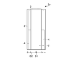
- FIG. 12 is a perspective view showing the left-hand grip body 2a of the exercise assistance device 1A according to the second embodiment of the present invention.
- 13A to 13C are views for explaining the operation of the fourth weight member 9.
- the exercise assistance device 1A of the second embodiment is the first implementation in that the holder 8 and the fourth weight member 9 are provided and the protrusion member 7 is not provided, compared to the exercise assistance device 1 of the first embodiment. It is different from the exercise assisting device 1 in the form. As illustrated in FIG. 12, the exercise assisting device 1 ⁇ / b> A according to the second embodiment does not include the protruding member 7 (see FIG. 1) and has a thumb as a holder as compared with the configuration of the exercise assisting device 1 according to the first embodiment. A holder 8 and a fourth weight member 9 are further provided.
- the thumb holder 8 is disposed on the rear side (minus side) of the grip member 3 in the front-rear direction (first direction D1) above the grip member 3.
- the thumb holder 8 covers the thumb in a state where it stands up.
- the thumb holder 8 is detachable from the grip member 3.
- the material of the thumb holder 8 is a material having safety so as not to damage the thumb.
- the thumb holder 8 has a U-shaped cross section when viewed from above and extends in the longitudinal direction L. In the thumb holder 8, the U-shaped open end is attached to the rear portion of the grip member 3. As shown in FIGS. 13A to 13C, the thumb holder 8 is configured so that the thumb in the upward standing state contacts the second weight member 5 and grips the grip body 2a. The surface of the opposite side (the rear side (minus side) of the gripping member 3 in the front-rear direction (first direction D1)) is covered. Thereby, the thumb holder 8 has a function of preventing the thumb from being largely separated from the gripping member 3 (second weight member 3 in the present embodiment).
- the fourth weight member 9 is attached to the upper side of the gripping member 3 as shown in FIG.
- the fourth weight member 9 is attached over the entire region in the longitudinal direction L of the thumb holder 8 on the rear side (minus side) of the thumb holder 8 in the front-rear direction (first direction D1).
- the fourth weight member 9 is a plate member parallel to the longitudinal direction L and the second direction D2 (left-right direction).
- the fourth weight member 9 can be replaced with one having a different weight.
- the operation of the thumb holder 8 will be described.
- the thumb holder 8 is disposed on the rear side (minus side) of the grip member 3 in the front-rear direction (first direction D1) and covers the thumb in a state where it is raised upward. Therefore, as shown in FIGS. 13A to 13C, the thumb holder 8 does not greatly separate the thumb from the grip member 3 (the second weight member 3 in the present embodiment). Thereby, the grip of the grip member 3 is stabilized, and the elbow can be pulled backward more greatly.
- the fourth weight member 9 is disposed on the rear side (minus side) of the thumb holder 8 in the front-rear direction (first direction D1). Therefore, as shown in FIGS. 13A to 13C, acceleration is performed upward with the base of the thumb as a center, like a seesaw in which the first weight member 4 is placed on one side and the fourth weight member 9 is placed on the other side. The operation of rotating while rotating and the operation of rotating while accelerating downward are repeated. Thereby, an arm can be easily shaken in the front-back direction. As a result, the swinging speed of the arm in the front-rear direction can be increased.
- the exercise assisting device 1A according to the second embodiment is arranged on the rear side (minus side) of the exercise assisting device 1A and the gripping member 3 in the front-rear direction (first direction D1) and with the thumb raised up.
- a covering thumb holder 8 is further provided. Therefore, the thumb holder 8 does not greatly separate the thumb from the grip member 3 side (the second weight member 3 in the present embodiment). Thereby, the grip of the grip member 3 is stabilized, and the elbow can be pulled backward more greatly.
- the exercise assisting device 1A further includes a fourth weight member 9 arranged on the rear side (minus side) of the thumb holder 8 in the front-rear direction (first direction D1). Therefore, around the base of the thumb, the operation of rotating while accelerating upward and the operation of rotating while accelerating downward are repeated. Thereby, an arm can be easily shaken in the front-back direction. As a result, the swinging speed of the arm in the front-rear direction can be increased.
- this invention can be implemented with a various form, without being limited to embodiment mentioned above.
- first embodiment the configuration in which the first weight member 4, the second weight member 5, the third weight member 6, and the protruding member 7 are all attached to the grip member 3 has been described.
- second embodiment the configuration in which the first weight member 4, the second weight member 5, the third weight member 6, and the fourth weight member 9 are all attached to the gripping member 3 has been described.
- any one or more of the first weight member 4, the second weight member 5, the third weight member 6, the protruding member 7, and the fourth weight member 9 may be attached to the grip member 3.
- the material of the grip member 3 is preferably a light material, but is not limited thereto.
- the material of the grip member 3 is not limited to a light material, and may be a heavy material such as a metal.
- the weights of the first weight member 4, the second weight member 5, the third weight member 6, and the fourth weight member 9 are preferably larger than the total weight of the gripping member 3.
- the material of the grip member 3 does not have to have the same specific gravity as a whole, and the distribution of weight may be changed inside.
- the specific weights of the first weight member 4, the second weight member 5, the third weight member 6, and the fourth weight member 9 are larger than the specific gravity of the grip member 3. Is preferred.
Abstract
This exercise assisting device 1 is provided with a grip member 3 that can be gripped by a hand and that extends in a tubular shape or in a columnar shape. The grip member 3 has a recessed part 31 configured so that, when the device is gripped by the hand, only a portion at which the middle finger is placed is recessed.
Description
本発明は、ジョギングやウォーキングなどに用いる運動補助器具に関する。
The present invention relates to an exercise assisting device used for jogging or walking.
従来、ジョギング(走行)やウォーキング(歩行)などに用いる運動補助器具として、表面に凹凸を有するバトン形状のグリップを備えるものが知られている(例えば、特許文献1参照)。特許文献1に記載のグリップは、一端から他端に向かうにしたがって細くなる筒状に形成されている。特許文献1に記載のグリップは、握る際に5本の指の形に合うような凹凸を有している。特許文献1に記載のグリップは、凹凸を有するグリップを握った状態で走行をすることで、身体のバランスの偏りを少なくことにより、より良いフォームで走ることができるとされている。
Conventionally, as an exercise assisting instrument used for jogging (running), walking (walking), etc., one having a baton-shaped grip having irregularities on the surface is known (for example, see Patent Document 1). The grip described in Patent Document 1 is formed in a cylindrical shape that becomes thinner from one end to the other end. The grip described in Patent Document 1 has irregularities that match the shape of five fingers when grasping. The grip described in Patent Document 1 is said to be able to run with a better form by running while holding a grip having unevenness, thereby reducing the balance of the balance of the body.
ところで、従来より、ジョギング(走行)やウォーキング(歩行)などにおいて、腕の正しい振り方が、走り方及び歩き方に影響を与えることが知られている。腕を正しく振ることができ、かつ、腕の振り方を安定させることができれば、安定した走行や歩行を実現することができると考えられる。
By the way, conventionally, it is known that how to swing the arm correctly affects how to run and walk in jogging (running) and walking (walking). If the arm can be shaken correctly and the manner of swinging the arm can be stabilized, stable running and walking can be realized.
しかしながら、特許文献1に記載の運動補助器具においては、身体のバランスの偏りに着目しており、腕の振り方については着目していない。そのため、走行や歩行の際に、腕を正しく振ることができ、かつ、腕の振り方を安定させることができる運動補助器具が望まれている。
However, in the exercise assistance device described in Patent Document 1, attention is paid to the bias of the balance of the body, and attention is not paid to how to swing the arm. Therefore, there is a demand for an exercise assisting device that can correctly swing an arm during running and walking and can stabilize the way of swinging the arm.
本発明は、走行や歩行の際に、腕を正しく振ることができ、かつ、腕の振り方を安定させることができる運動補助器具を提供することを目的とする。
An object of the present invention is to provide an exercise assisting device that can correctly swing an arm during running and walking and can stabilize the way of swinging the arm.
本発明は、手で握ることが可能な筒状又は柱状に延びる握り部材を備え、前記握り部材は、手で握る際に中指が配置される部分のみが窪む凹部を有する運動補助器具に関する。
The present invention relates to an exercise assisting device including a gripping member extending in a cylindrical shape or a columnar shape that can be gripped by a hand, and the gripping member has a concave portion in which only a portion where a middle finger is disposed when gripped by a hand.
また、前記握り部材を立てた状態で人の前方で前記握り部材を握る場合に、前記握り部材の前方は人の前方に対応し、前記握り部材の後方は人の後方に対応しており、前記運動補助器具は、前記握り部材の後方側の下部に配置される第1ウエイト部材を更に備えることが好ましい。
Further, when gripping the grip member in front of a person with the grip member in a standing state, the front of the grip member corresponds to the front of the person, and the rear of the grip member corresponds to the back of the person, It is preferable that the exercise assisting device further includes a first weight member disposed at a lower part on the rear side of the grip member.
また、前記握り部材を立てた状態で人の前方で前記握り部材を握る場合に、前記握り部材の前方は人の前方に対応し、前記握り部材の後方は人の後方に対応しており、前記運動補助器具は、前記握り部材の後方側に配置されると共に、前記握り部材の長手方向に延びる第2ウエイト部材を更に備えることが好ましい。
Further, when gripping the grip member in front of a person with the grip member in a standing state, the front of the grip member corresponds to the front of the person, and the rear of the grip member corresponds to the back of the person, It is preferable that the exercise assisting device further includes a second weight member disposed on the rear side of the grip member and extending in a longitudinal direction of the grip member.
また、前記握り部材を立てた状態で人の前方で前記握り部材を握る場合に、前記握り部材の前方は人の前方に対応し、前記握り部材の後方は人の後方に対応し、前記握り部材の外方は、人の左右方向のいずれか一方の外方に対応しており、前記運動補助器具は、前記握り部材の一方の外方側の側部に配置されると共に、前記握り部材の長手方向に延びる第3ウエイト部材を更に備えることが好ましい。
Further, when the grip member is gripped in front of a person with the grip member standing, the front of the grip member corresponds to the front of the person, the rear of the grip member corresponds to the rear of the person, and the grip The outer side of the member corresponds to the outer side of either one of the left and right directions of the person, and the exercise assisting device is disposed on one outer side of the grip member, and the grip member It is preferable to further include a third weight member extending in the longitudinal direction.
また、前記握り部材を握る場合に、薬指と小指との間に配置される突出部を更に備えることが好ましい。
Further, when gripping the grip member, it is preferable to further include a projecting portion disposed between the ring finger and the little finger.
また、前記握り部材を立てた状態で人の前方で前記握り部材を握る場合に、前記握り部材の前方は人の前方に対応し、前記握り部材の後方は人の後方に対応しており、前記運動補助器具は、前記握り部材の後方側に配置されると共に上方へ立てた状態の親指を覆うホルダーを更に備えることが好ましい。
Further, when gripping the grip member in front of a person with the grip member in a standing state, the front of the grip member corresponds to the front of the person, and the rear of the grip member corresponds to the back of the person, It is preferable that the exercise assisting device further includes a holder that is disposed on the rear side of the gripping member and covers the thumb in a state of standing upward.
また、前記運動補助器具は、前記ホルダーの後方側に配置される第4ウエイト部材を更に備えることが好ましい。
Moreover, it is preferable that the exercise assisting device further includes a fourth weight member disposed on the rear side of the holder.
本発明によれば、走行や歩行の際に、腕を正しく振ることができ、かつ、腕の振り方を安定させることができる運動補助器具を提供することができる。
According to the present invention, it is possible to provide an exercise assisting device that can correctly swing an arm during running or walking and can stabilize the manner of swinging the arm.
適宜図面を参照しつつ、本発明に係る第1実施形態の運動補助器具1について具体的に説明する。図1は、本発明の第1実施形態の運動補助器具1の左手用のグリップ体2aを示す斜視図である。図2は、グリップ体2aの分解斜視図である。図3は、グリップ体2aを、図2とは異なる角度から視た分解斜視図である。図4Aは図1に示すグリップ体2aを第2方向D2(左右方向)のマイナス側(左手用のグリップ体2aの内方側)から視た図であり、図4Bは図1に示すグリップ体2aを第1方向D1(前後方向)のプラス側(前方側)から視た図であり、図4Cは図1に示すグリップ体2aを第2方向D2(左右方向)のプラス側(左手用のグリップ体2aの外方側)から視た図であり、図4Dは図1に示すグリップ体2aを第1方向D1(前後方向)のマイナス側(後方側)から視た図である。
The exercise assistance device 1 according to the first embodiment of the present invention will be specifically described with reference to the drawings as appropriate. FIG. 1 is a perspective view showing a left hand grip body 2a of an exercise assistance device 1 according to a first embodiment of the present invention. FIG. 2 is an exploded perspective view of the grip body 2a. FIG. 3 is an exploded perspective view of the grip body 2a viewed from an angle different from that in FIG. 4A is a view of the grip body 2a shown in FIG. 1 as viewed from the minus side in the second direction D2 (left-right direction) (inward side of the grip body 2a for the left hand), and FIG. 4B is a grip body shown in FIG. FIG. 4C is a view of the grip body 2a shown in FIG. 1 in the second direction D2 (left and right direction) plus side (for the left hand). FIG. 4D is a view of the grip body 2a shown in FIG. 1 viewed from the minus side (rear side) of the first direction D1 (front-rear direction).
本発明に係る運動補助器具1は、短距離走やジョギング等の走行やウォーキング等の歩行などに用いられる。運動補助器具1は、左右一対のグリップ体2を備える。一対のグリップ体2は、左手用及び右手用の一対で構成される。運動補助器具12は、通常使用する際には、左手用のグリップ体2a及び右手用のグリップ体2bが同時に使用される。本実施形態における図1~図4Dに示すグリップ体2aは、左手用について説明している。以下に説明する左手用のグリップ体2aを構成する各構成部材は、右手用のグリップ体2bを構成する各構成部材とは、左右対称である。なお、右手用のグリップ体2bは、図8A~図11Bにおいて図示しているが、図1~図7においては、図示を省略している。
The exercise assisting apparatus 1 according to the present invention is used for running such as short-distance running or jogging or walking such as walking. The exercise assisting device 1 includes a pair of left and right grip bodies 2. The pair of grip bodies 2 is composed of a pair for left hand and right hand. When the exercise assisting device 12 is normally used, the left hand grip body 2a and the right hand grip body 2b are simultaneously used. The grip body 2a shown in FIGS. 1 to 4D in the present embodiment is described for the left hand. The constituent members constituting the left-hand grip body 2a described below are symmetrical to the constituent members constituting the right-hand grip body 2b. Note that the grip body 2b for the right hand is illustrated in FIGS. 8A to 11B, but is not illustrated in FIGS.
左手用のグリップ体2aは、図1~図4Dに示すように、左手用の握り部材3(握り部材)と、第1ウエイト部材4と、第2ウエイト部材5と、第3ウエイト部材6と、突起部材7(突出部)と、を備える。
As shown in FIGS. 1 to 4D, the left hand grip body 2a includes a left hand grip member 3 (grip member), a first weight member 4, a second weight member 5, and a third weight member 6. And a protruding member 7 (protruding portion).
なお、図面において、握り部材3が延びる方向を長手方向Lという。また、グリップ体2aの第1方向D1及び第2方向D2は、互いに直交する方向である。第1方向D1及び第2方向D2は、それぞれ、長手方向Lに直交する。第1方向D1は、握り部材3の前後方向であって、握り部材3を立てた状態で人の前方で握り部材3を握る場合(図5参照)において、握り部材3を握る人から視た場合の人の前後方向に対応する方向である。第1方向D1において、プラス(+)側は人の前方側に対応し、マイナス(-)側は人の後方側に対応する。
In the drawing, the direction in which the gripping member 3 extends is referred to as the longitudinal direction L. The first direction D1 and the second direction D2 of the grip body 2a are directions orthogonal to each other. The first direction D1 and the second direction D2 are each orthogonal to the longitudinal direction L. The first direction D1 is the front-rear direction of the gripping member 3, and is viewed from the person who grips the gripping member 3 when the gripping member 3 is gripped in front of the person with the gripping member 3 standing (see FIG. 5). The direction corresponds to the front-rear direction of the person in the case. In the first direction D1, the plus (+) side corresponds to the front side of the person, and the minus (−) side corresponds to the back side of the person.
第2方向D2は、握り部材3の左右方向であって、握り部材3を立てた状態で人の前方で握り部材3を握る場合(図5参照)において、握り部材3を握る人から視た場合の人の左右方向に対応する方向である。
第2方向D2のプラス(+)側は、握り部材3の一方の外方側であって、人の左右方向のいずれか一方の外方側に対応する。具体的には、第2方向D2(左右方向)のプラス(+)側(外方側)は、左手用の握り部材3を握った場合には、左手用の握り部材3を基準として左側である。また、第2方向D2(左右方向)のプラス(+)側(外方側)は、右手用の握り部材3を握った場合には、右手用の握り部材3を基準として右側である。
第2方向D2のマイナス(-)側は、握り部材3の一方の内方側であって、人の左右方向のいずれか一方の内方側に対応する。具体的には、第2方向D2(左右方向)のマイナス(-)側(内方側)は、左手用の握り部材3を握った場合には、左手用の握り部材3を基準として右側である。また、第2方向D2(左右方向)のマイナス(-)側(内方側)は、右手用の握り部材3を握った場合には、右手用の握り部材3を基準として左側である。
なお、グリップ体2aは人に握られた状態で振られるため、グリップ体2aの位置により、握り部材3を握る人から視た場合のグリップ体2aの向きは変化する。 The second direction D2 is the left-right direction of thegrip member 3, and is viewed from the person who grips the grip member 3 when the grip member 3 is gripped in front of the person with the grip member 3 standing (see FIG. 5). The direction corresponds to the left and right direction of the person in the case.
The plus (+) side of the second direction D2 is one outer side of thegrip member 3, and corresponds to one outer side in the left-right direction of the person. Specifically, the plus (+) side (outward side) of the second direction D2 (left and right direction) is the left side with respect to the left hand grip member 3 when the left hand grip member 3 is gripped. is there. Further, the plus (+) side (outward side) of the second direction D2 (left and right direction) is the right side with respect to the right hand grip member 3 when the right hand grip member 3 is gripped.
The minus (−) side of the second direction D2 is one inward side of thegrip member 3, and corresponds to one inward side in the left-right direction of the person. Specifically, the minus (−) side (inward side) of the second direction D2 (left and right direction) is the right side with respect to the left hand grip member 3 when the left hand grip member 3 is gripped. is there. Further, the minus (−) side (inward side) of the second direction D2 (left and right direction) is the left side with respect to the right hand grip member 3 when the right hand grip member 3 is gripped.
Since thegrip body 2a is shaken while being held by a person, the orientation of the grip body 2a when viewed from the person holding the grip member 3 changes depending on the position of the grip body 2a.
第2方向D2のプラス(+)側は、握り部材3の一方の外方側であって、人の左右方向のいずれか一方の外方側に対応する。具体的には、第2方向D2(左右方向)のプラス(+)側(外方側)は、左手用の握り部材3を握った場合には、左手用の握り部材3を基準として左側である。また、第2方向D2(左右方向)のプラス(+)側(外方側)は、右手用の握り部材3を握った場合には、右手用の握り部材3を基準として右側である。
第2方向D2のマイナス(-)側は、握り部材3の一方の内方側であって、人の左右方向のいずれか一方の内方側に対応する。具体的には、第2方向D2(左右方向)のマイナス(-)側(内方側)は、左手用の握り部材3を握った場合には、左手用の握り部材3を基準として右側である。また、第2方向D2(左右方向)のマイナス(-)側(内方側)は、右手用の握り部材3を握った場合には、右手用の握り部材3を基準として左側である。
なお、グリップ体2aは人に握られた状態で振られるため、グリップ体2aの位置により、握り部材3を握る人から視た場合のグリップ体2aの向きは変化する。 The second direction D2 is the left-right direction of the
The plus (+) side of the second direction D2 is one outer side of the
The minus (−) side of the second direction D2 is one inward side of the
Since the
握り部材3は、図1~図4Dに示すように、長手方向Lに延びる。握り部材3は、左手で握ることが可能な筒状又は柱状に形成される。本実施形態においては、握り部材3は、略円筒状又は略円柱状である。なお、握り部材3は、略円筒状又は略円柱状に限定されず、例えば、多角筒状又は多角柱状であってもよい。
The gripping member 3 extends in the longitudinal direction L as shown in FIGS. 1 to 4D. The grip member 3 is formed in a cylindrical shape or a column shape that can be gripped with the left hand. In this embodiment, the grip member 3 is substantially cylindrical or substantially columnar. In addition, the grip member 3 is not limited to a substantially cylindrical shape or a substantially columnar shape, and may be a polygonal cylinder shape or a polygonal column shape, for example.
握り部材3の太さは、握り部材3の周方向に沿って指を延ばした状態で、握り部材3を握ることが可能な太さである。握り部材3の材料は、軽い素材であることが好ましく、例えば、プラスチック材や段ボール材などで構成される。また、握り部材3の材質は、手に馴染み易い素材が好ましい。
The thickness of the gripping member 3 is a thickness that allows the gripping member 3 to be gripped in a state where the finger is extended along the circumferential direction of the gripping member 3. The material of the grip member 3 is preferably a light material, and is made of, for example, a plastic material or a cardboard material. Moreover, the material of the grip member 3 is preferably a material that can be easily adapted to the hand.
握り部材3には、凹溝31(凹部)が設けられる。凹溝31は、長手方向Lの略中央部において、第1方向D1(前後方向)のプラス側(前方側)の面に、第2方向D2(左右方向)に延びる溝状に形成される。凹溝31は、握り部材3を手で握る際に、握り部材3において、中指が配置される部分のみが窪む部分である。凹溝31の溝の幅は、中指を配置可能な幅である。
The grip member 3 is provided with a concave groove 31 (concave portion). The concave groove 31 is formed in a groove shape extending in the second direction D2 (left-right direction) on the surface on the plus side (front side) of the first direction D1 (front-rear direction) at a substantially central portion in the longitudinal direction L. The concave groove 31 is a portion where only the portion where the middle finger is disposed in the grip member 3 is recessed when the grip member 3 is gripped by hand. The width of the groove of the concave groove 31 is a width in which the middle finger can be arranged.
握り部材3は、図2に示すように、第1ウエイト取付部32と、第2ウエイト取付部33と、第3ウエイト取付部34と、突起取付部35と、を有する。第1ウエイト取付部32及び第2ウエイト取付部33は、握り部材3における第1方向D1(前後方向)のマイナス側(後方側)の側部に平面状に形成される。第3ウエイト取付部34は、握り部材3における第2方向D2(左右方向)のプラス側(外方側)の側部に平面状に形成される。
As shown in FIG. 2, the gripping member 3 includes a first weight attachment portion 32, a second weight attachment portion 33, a third weight attachment portion 34, and a protrusion attachment portion 35. The first weight attachment portion 32 and the second weight attachment portion 33 are formed in a planar shape on the minus side (rear side) side portion of the grip member 3 in the first direction D1 (front-rear direction). The third weight attachment portion 34 is formed in a planar shape on the plus side (outward side) side portion of the grip member 3 in the second direction D2 (left-right direction).
第1ウエイト取付部32には、後述する第1ウエイト部材4が取り付けられる。第1ウエイト取付部32は、握り部材3における第1方向D1(前後方向)のマイナス側(後方側)の平面である。第1ウエイト取付部32は、握り部材3における長手方向Lの略中央から下方側の略半分の平面により構成される。第1ウエイト取付部32は、後述する第2ウエイト取付部33よりも一段低い平面である。
A first weight member 4 to be described later is attached to the first weight attachment portion 32. The first weight attachment portion 32 is a flat surface on the minus side (rear side) of the grip member 3 in the first direction D1 (front-rear direction). The first weight attachment portion 32 is configured by a substantially half plane on the lower side from the approximate center in the longitudinal direction L of the grip member 3. The first weight attachment portion 32 is a plane that is one step lower than a second weight attachment portion 33 described later.
第2ウエイト取付部33には、後述する第2ウエイト部材5が取り付けられる。第2ウエイト取付部33は、握り部材3における第1方向D1(前後方向)のマイナス側(後方側)の平面である。第2ウエイト取付部33は、握り部材3における長手方向Lの略中央から上方側の略半分の平面により、構成される。第2ウエイト取付部33は、第1ウエイト取付部32よりも一段高い平面である。
2nd weight member 5 mentioned below is attached to the 2nd weight attaching part 33. The second weight attachment portion 33 is a flat surface on the minus side (rear side) of the grip member 3 in the first direction D1 (front-rear direction). The second weight attachment portion 33 is configured by a substantially half plane on the upper side from the approximate center in the longitudinal direction L of the grip member 3. The second weight attachment portion 33 is a flat surface that is one step higher than the first weight attachment portion 32.
第3ウエイト取付部34には、後述する第3ウエイト部材6が取り付けられる。第3ウエイト取付部34は、握り部材3における第2方向D2(左右方向)のプラス側(外方側)の平面である。第3ウエイト取付部34は、長手方向Lの全域に亘って延びる平面である。
The third weight member 6 to be described later is attached to the third weight attachment portion 34. The third weight attachment portion 34 is a plane on the plus side (outward side) of the grip member 3 in the second direction D2 (left-right direction). The third weight attachment portion 34 is a plane extending over the entire area in the longitudinal direction L.
突起取付部35は、後述する突起部材7が取り付けられる。突起取付部35に取り付けられる突起部材7は、握り部材3を握る場合に薬指と小指との間に配置される。突起取付部35は、図2に示すように、握り部材3における第1方向D1(前後方向)のプラス側(前方側)の外周面において、下方側における第3ウエイト取付部34寄りに設けられる所定範囲の曲面である。
The protrusion attachment part 35 is attached with a protrusion member 7 to be described later. The protrusion member 7 attached to the protrusion attachment portion 35 is disposed between the ring finger and the little finger when gripping the grip member 3. As shown in FIG. 2, the protrusion attachment portion 35 is provided near the third weight attachment portion 34 on the lower side on the outer peripheral surface of the grip member 3 on the plus side (front side) in the first direction D <b> 1 (front-rear direction). A curved surface within a predetermined range.
第1ウエイト部材4、第2ウエイト部材5及び第3ウエイト部材6は、握り部材3のバランス調整用の錘である。第1ウエイト部材4、第2ウエイト部材5及び第3ウエイト部材6は、握り部材3の材料よりも比重が大きい材料、例えば金属で構成される。
The first weight member 4, the second weight member 5, and the third weight member 6 are weights for adjusting the balance of the grip member 3. The first weight member 4, the second weight member 5, and the third weight member 6 are made of a material having a specific gravity greater than that of the grip member 3, for example, a metal.
第1ウエイト部材4、第2ウエイト部材5及び第3ウエイト部材6は、図1~図4Dに示すように、それぞれ、握り部材3に対して着脱可能に構成される。第1ウエイト部材4、第2ウエイト部材5及び第3ウエイト部材6は、それぞれ、重量を選択して設定可能である。第1ウエイト部材4、第2ウエイト部材5及び第3ウエイト部材6は、重量及び組み合わせを適宜選択して設定可能である。
The first weight member 4, the second weight member 5, and the third weight member 6 are configured to be detachable from the grip member 3, as shown in FIGS. The first weight member 4, the second weight member 5, and the third weight member 6 can each be set by selecting a weight. The first weight member 4, the second weight member 5, and the third weight member 6 can be set by appropriately selecting the weight and combination.
第1ウエイト部材4は、握り部材3の第1ウエイト取付部32に取り付けられる。第1ウエイト部材4は、握り部材3における第1方向D1(前後方向)のマイナス側(後方側)の第1ウエイト取付部32の平面において、下方側の略半分に取り付けられる。第1ウエイト部材4は、握り部材3の長手方向Lに延びる。第1ウエイト部材4は、長手方向L及び第2方向D2(左右方向)に平行な板部材である。
The first weight member 4 is attached to the first weight attachment portion 32 of the grip member 3. The first weight member 4 is attached to a substantially half on the lower side in the plane of the first weight attachment portion 32 on the minus side (rear side) of the grip member 3 in the first direction D1 (front-rear direction). The first weight member 4 extends in the longitudinal direction L of the gripping member 3. The first weight member 4 is a plate member parallel to the longitudinal direction L and the second direction D2 (left-right direction).
第2ウエイト部材5は、第1ウエイト部材4が握り部材3に取り付けられた後に、第1ウエイト部材4における第1方向D1(前後方向)のマイナス側(後方側)の面と、第2ウエイト取付部33の平面とに跨って、取り付けられる。第2ウエイト部材5は、握り部材3の長手方向Lの全域に亘って延びる。第2ウエイト部材5は、長手方向L及び第2方向D2(左右方向)に平行な板部材である。
After the first weight member 4 is attached to the gripping member 3, the second weight member 5 includes a negative side (rear side) surface of the first weight member 4 in the first direction D1 (front-rear direction), and a second weight. It is mounted across the plane of the mounting portion 33. The second weight member 5 extends over the entire length direction L of the grip member 3. The second weight member 5 is a plate member parallel to the longitudinal direction L and the second direction D2 (left-right direction).
第3ウエイト部材6は、握り部材3の第3ウエイト取付部34に取り付けられる。第3ウエイト部材6は、握り部材3における第2方向D2(左右方向)のプラス側(外方側)の第3ウエイト取付部34に取り付けられる。第3ウエイト部材6は、握り部材3の長手方向Lに延びる。第3ウエイト部材6は、長手方向L及び第1方向D1(前後方向)に平行な板部材である。
The third weight member 6 is attached to the third weight attachment portion 34 of the gripping member 3. The third weight member 6 is attached to the third weight attachment portion 34 on the plus side (outward side) of the grip member 3 in the second direction D2 (left-right direction). The third weight member 6 extends in the longitudinal direction L of the gripping member 3. The third weight member 6 is a plate member parallel to the longitudinal direction L and the first direction D1 (front-rear direction).
突起部材7は、握り部材3に対して着脱可能に構成される。例えば、突起部材7は、嵌合凸部(図示せず)を有し、握り部材3は、嵌合凹部(図示せず)を有する。突起部材7の嵌合凸部が握り部材3の嵌合凹部に嵌め合わされることで、突起部材7は、握り部材3に対して着脱可能な構成となる。
The protruding member 7 is configured to be detachable from the gripping member 3. For example, the protrusion member 7 has a fitting convex part (not shown), and the grip member 3 has a fitting concave part (not shown). By fitting the fitting convex portion of the protruding member 7 into the fitting concave portion of the gripping member 3, the protruding member 7 can be attached to and detached from the gripping member 3.
突起部材7は、突起取付部35に取り付けられる。突起部材7は、握り部材3の外面から外部に向けて突出している。突起部材7は、握り部材3を握る場合に薬指と小指との間に配置される。突起部材7は、握り部材3における第1方向D1(前後方向)のプラス側(前方側)において、第2方向D2(左右方向)のプラス側(外方側)の下方における第3ウエイト部材6寄りの突起取付部35に配置される。突起部材7は、後述する水平動作モードで運動補助器具1を使用する際に装着され、オプション部材として使用される。
The protrusion member 7 is attached to the protrusion attachment portion 35. The protruding member 7 protrudes outward from the outer surface of the gripping member 3. The protruding member 7 is disposed between the ring finger and the little finger when the gripping member 3 is gripped. The protruding member 7 is a third weight member 6 below the plus side (outside) of the second direction D2 (left-right direction) on the plus side (front side) of the first direction D1 (front-back direction) of the grip member 3. It is arranged on the projection mounting part 35 on the side. The protruding member 7 is mounted when the exercise assisting device 1 is used in a horizontal operation mode described later, and is used as an optional member.
次に、運動補助器具1の使用方法及び各部材の作用について、図面を参照しながら説明する。図5は、グリップ体2aの握り方を説明するための図であって、握り部材3の凹溝31へ中指を配置する状態を説明する図である。図6A及び図6Bは、グリップ体2aの握り方を説明するための図であって、親指をグリップ体2aに配置する状態を説明する図である。図7は、第1ウエイト部材4の作用を説明するための図である。図8A~図8Cは、第2ウエイト部材5の作用を説明するための図である。図9A及び図9Bは、第3ウエイト部材6の作用を説明するための図である。図10は、第1ウエイト部材4と第3ウエイト部材6とを併せて備えることで奏される作用を説明するための図である。図11A及び図11Bは、突起部材7の作用を説明するための図である。
Next, the method of using the exercise assisting apparatus 1 and the operation of each member will be described with reference to the drawings. FIG. 5 is a view for explaining how to grip the grip body 2 a and is a view for explaining a state in which the middle finger is arranged in the concave groove 31 of the grip member 3. 6A and 6B are diagrams for explaining how to grip the grip body 2a, and are diagrams illustrating a state in which the thumb is disposed on the grip body 2a. FIG. 7 is a view for explaining the operation of the first weight member 4. 8A to 8C are views for explaining the operation of the second weight member 5. 9A and 9B are views for explaining the operation of the third weight member 6. FIG. 10 is a view for explaining an effect produced by providing the first weight member 4 and the third weight member 6 together. 11A and 11B are diagrams for explaining the operation of the protruding member 7.
まず、運動補助器具1の使用方法について説明する。運動補助器具1のグリップ体2を握る際には、図5~図6Bに示すように、中指を握り部材3の凹溝31に配置する。同時に、図6A及び図6Bに示すように、親指を立てた状態で親指の付け根(拇指球)の部分から先端の部分までを第2ウエイト部材5にあてがうようにして、第2ウエイト部材5に、親指を接触させる。この状態で、グリップ体2を握る。
First, the method of using the exercise assistance device 1 will be described. When the grip body 2 of the exercise assisting device 1 is gripped, the middle finger is disposed in the concave groove 31 of the gripping member 3 as shown in FIGS. 5 to 6B. At the same time, as shown in FIG. 6A and FIG. 6B, the second weight member 5 is applied to the second weight member 5 so that the portion from the base of the thumb (finger ball) to the tip portion is applied to the second weight member 5 with the thumb standing. Touch the thumb. In this state, the grip body 2 is gripped.
また、後述する水平動作モードで運動補助器具1を使用する際には、オプション部材として突起部材7を握り部材3に取り付け、突起部材7を薬指と小指との間に配置した状態で、グリップ体2を握る(図11A及び図11B参照)。
Further, when using the exercise assisting instrument 1 in the horizontal operation mode to be described later, the gripping body 7 is attached to the gripping member 3 as an optional member, and the protruding member 7 is disposed between the ring finger and the little finger. 2 (see FIGS. 11A and 11B).
ジョギング等の走行をする際やウォーキング等の歩行をする際に、両手それぞれでグリップ体2を握った状態で、腕を前後方向に振る。これにより、両手それぞれに握られたグリップ体2は、前後方向に振られる。
ここで、運動補助器具1の主な特徴的な構造について、走行をする際や歩行をする際における腕の振り方への作用について説明する。 When running such as jogging or walking such as walking, the arm is swung in the front-rear direction while holding thegrip body 2 with both hands. Thereby, the grip body 2 held by both hands is swung in the front-rear direction.
Here, the main characteristic structure of the exercise assisting device 1 will be described in terms of the effect on how to swing the arm when running or walking.
ここで、運動補助器具1の主な特徴的な構造について、走行をする際や歩行をする際における腕の振り方への作用について説明する。 When running such as jogging or walking such as walking, the arm is swung in the front-rear direction while holding the
Here, the main characteristic structure of the exercise assisting device 1 will be described in terms of the effect on how to swing the arm when running or walking.
握り部材3の凹溝31の作用について説明する。
本発明の運動補助器具1を使用しないで走行又は歩行する場合には、本発明の運動補助器具1を使用する場合に比べて、次に説明する第1の走行状態、第2の走行状態、第3の走行状態及び第4の走行状態のように、走行又は歩行が安定しないことがある。 The operation of theconcave groove 31 of the grip member 3 will be described.
When running or walking without using the exercise assisting apparatus 1 of the present invention, compared to the case of using the exercise assisting apparatus 1 of the present invention, a first traveling state, a second traveling state, which will be described below, As in the third traveling state and the fourth traveling state, traveling or walking may not be stable.
本発明の運動補助器具1を使用しないで走行又は歩行する場合には、本発明の運動補助器具1を使用する場合に比べて、次に説明する第1の走行状態、第2の走行状態、第3の走行状態及び第4の走行状態のように、走行又は歩行が安定しないことがある。 The operation of the
When running or walking without using the exercise assisting apparatus 1 of the present invention, compared to the case of using the exercise assisting apparatus 1 of the present invention, a first traveling state, a second traveling state, which will be described below, As in the third traveling state and the fourth traveling state, traveling or walking may not be stable.
第1の走行状態は、何も器具を使用せずに、拳を強く握った状態で、肘を引いて走行又は歩行する状態である。第1の走行状態においては、拳を強く握っているため、拳が安定しており、腕を上下方向に動かしやすい。しかし、第1の走行状態においては、拳に力が入り、脇が締まり過ぎた状態となるため、真後ろに肘を大きく引きにくい状態となる。そのため、腕を後ろに引きにくく、走行が不安定になりやすい。
The first running state is a state in which an elbow is pulled and a person walks or walks while holding a fist without using any equipment. In the first running state, since the fist is firmly held, the fist is stable and the arm can be easily moved up and down. However, in the first running state, force is applied to the fist and the side is too tight, so that it is difficult to pull the elbow greatly behind. For this reason, it is difficult to pull the arm backward, and the running tends to be unstable.
第2の走行状態は、何も器具を使用せずに、人差し指のみに力を入れて折り曲げると共に、人差し指以外の指を開いた状態で、走行又は歩行する状態である。第2の走行状態においては、手の掌底(掌の下部)が下を向き、脇が開いた状態となる。そのため、脇が開いた状態で腕が前後方向に振られるため、走行が不安定になりやすい。
The second running state is a state in which a user runs and walks with only the index finger being folded without using any equipment and with fingers other than the index finger opened. In the second running state, the palm of the hand (lower part of the palm) faces down and the sides are open. For this reason, the arms are swung in the front-rear direction with the sides open, and thus traveling tends to become unstable.
第3の走行状態は、何も器具を使用せずに、小指又は薬指にのみに力を入れて折り曲げると共に、その他の折り曲げた指以外の指を開いた状態で、走行又は歩行する状態である。第3の走行状態においては、手の掌底(掌の下部)が上を向き、脇が開いた状態となる。そのため、脇が開いた状態で腕が前後方向に振られるため、走行が不安定になりやすい。
The third running state is a state in which a device is used to fold only by putting power on only the little finger or ring finger without using any instrument, and in a state where other fingers other than the folded finger are opened. . In the third running state, the palm of the hand (lower part of the palm) faces up and the sides are open. For this reason, the arms are swung in the front-rear direction with the sides open, and thus traveling tends to become unstable.
第4の走行状態は、周面に凹凸を有さない円筒状の通常のバトンを使用して、そのバトンを握って、走行又は歩行する状態である。第4の走行状態においては、凹凸を有さないバトンの周面上に複数の指が並んで配置されるため、各指の力の加減がバラバラとなり、安定性に欠ける。また、第4の走行状態においては、腕が動く度にその指の力のバランスが変化するため、手首が左右に不規則に動きやすくなる。そのため、走行が不安定になりやすい。
The fourth running state is a state in which a normal baton having a cylindrical shape having no irregularities on the peripheral surface is used, and the baton is gripped to run or walk. In the fourth running state, since a plurality of fingers are arranged side by side on the circumferential surface of the baton having no irregularities, the strength of each finger is varied and lacks stability. Further, in the fourth running state, the balance of the finger force changes each time the arm moves, so that the wrist easily moves irregularly from side to side. Therefore, traveling tends to be unstable.
このように、第1の走行状態、第2の走行状態、第3の走行状態及び第4の走行状態は、走行が不安定になりやすい。これに対して、本発明によれば、凹溝31に中指を配置した状態で、握り部材3を握ることができる。これにより、脇が締まった状態で腕を前後方向に振ることができる。また、拳を人体の真横に沿わせた状態で腕を上下方向に振ることができる。また、腕を振る際に、肘を真後ろに大きく引くことができる。
Thus, in the first traveling state, the second traveling state, the third traveling state, and the fourth traveling state, traveling is likely to be unstable. On the other hand, according to the present invention, the grip member 3 can be gripped with the middle finger placed in the concave groove 31. As a result, the arm can be swung in the front-rear direction with the sides tightened. In addition, the arm can be swung up and down with the fist placed beside the human body. Also, when swinging the arm, the elbow can be pulled greatly behind.
次に、第1ウエイト部材4、第2ウエイト部材5及び第3ウエイト部材6の作用について説明する。ここで、第1ウエイト部材4、第2ウエイト部材5及び第3ウエイト部材6の作用の説明においては、握り部材3には、第1ウエイト部材4、第2ウエイト部材5及び第3ウエイト部材6が取り付けられている状態で説明する。なお、第1ウエイト部材4、第2ウエイト部材5及び第3ウエイト部材6の作用の説明においては、握り部材3には、突起部材7は取り付けられていない。
Next, the operation of the first weight member 4, the second weight member 5, and the third weight member 6 will be described. Here, in the description of the operation of the first weight member 4, the second weight member 5, and the third weight member 6, the gripping member 3 includes the first weight member 4, the second weight member 5, and the third weight member 6. A description will be given with the attached. In the description of the operation of the first weight member 4, the second weight member 5, and the third weight member 6, the protruding member 7 is not attached to the gripping member 3.
まず、第1ウエイト部材4の作用について説明する。
第1ウエイト部材4は、握り部材3の前後方向(第1方向D1)の後方側(マイナス側)の下部に配置される。図7に示すように、第1ウエイト部材4は、握り部材3の後方側の下部において、低い重心となる。第1ウエイト部材4が握り部材3の低い重心となり、グリップ体2を両手に握って前後方向に振ることで、腕は、肩を中心軸として、スイングされる。ここで、例えば、ブランコがスイングされる場合には、図7に示すように、ブランコに乗る人の重心が低い位置にあるために、ブランコは、大きく速いスイングとなる。これと同様に、本発明においては、第1ウエイト部材4が握り部材3の後方側の下部に配置されるため、ブランコがスイングされるように、第1ウエイト部材4の低い重心により、腕の振りを大きく強くすることができる。 First, the operation of thefirst weight member 4 will be described.
Thefirst weight member 4 is disposed at a lower portion on the rear side (minus side) of the grip member 3 in the front-rear direction (first direction D1). As shown in FIG. 7, the first weight member 4 has a low center of gravity in the lower part on the rear side of the gripping member 3. The first weight member 4 becomes a low center of gravity of the gripping member 3, and the arm is swung with the shoulder as the central axis by grasping the grip body 2 with both hands and swinging in the front-rear direction. Here, for example, when the swing is swung, as shown in FIG. 7, the swing of the swing is large and fast because the center of gravity of the person on the swing is at a low position. Similarly, in the present invention, since the first weight member 4 is disposed at the lower part on the rear side of the gripping member 3, the lower center of gravity of the first weight member 4 causes the swing of the swing so that the swing is swung. The swing can be greatly increased.
第1ウエイト部材4は、握り部材3の前後方向(第1方向D1)の後方側(マイナス側)の下部に配置される。図7に示すように、第1ウエイト部材4は、握り部材3の後方側の下部において、低い重心となる。第1ウエイト部材4が握り部材3の低い重心となり、グリップ体2を両手に握って前後方向に振ることで、腕は、肩を中心軸として、スイングされる。ここで、例えば、ブランコがスイングされる場合には、図7に示すように、ブランコに乗る人の重心が低い位置にあるために、ブランコは、大きく速いスイングとなる。これと同様に、本発明においては、第1ウエイト部材4が握り部材3の後方側の下部に配置されるため、ブランコがスイングされるように、第1ウエイト部材4の低い重心により、腕の振りを大きく強くすることができる。 First, the operation of the
The
次に、第2ウエイト部材5の作用について説明する。
第2ウエイト部材5は、握り部材3の前後方向(第1方向D1)の後方側(マイナス側)に配置されると共に、握り部材3の長手方向Lに延びる。ここで、縦長の重量構造物は、上下方向の運動において安定度が高い。これと同様に、図8A~図8Cに示すように、本発明においては、握り部材3が第2ウエイト部材5を備えるため、上下方向の運動を安定させることができる。これにより、第2ウエイト部材5は、人が走行又は歩行する場合に、グリップ体2を振る際に、上下方向の運動を安定させることができる。 Next, the operation of thesecond weight member 5 will be described.
Thesecond weight member 5 is disposed on the rear side (minus side) of the grip member 3 in the front-rear direction (first direction D1) and extends in the longitudinal direction L of the grip member 3. Here, the vertically long heavy structure has high stability in the vertical movement. Similarly, as shown in FIGS. 8A to 8C, in the present invention, since the gripping member 3 includes the second weight member 5, the vertical movement can be stabilized. Thereby, when the person runs or walks, the second weight member 5 can stabilize the vertical movement when the grip body 2 is shaken.
第2ウエイト部材5は、握り部材3の前後方向(第1方向D1)の後方側(マイナス側)に配置されると共に、握り部材3の長手方向Lに延びる。ここで、縦長の重量構造物は、上下方向の運動において安定度が高い。これと同様に、図8A~図8Cに示すように、本発明においては、握り部材3が第2ウエイト部材5を備えるため、上下方向の運動を安定させることができる。これにより、第2ウエイト部材5は、人が走行又は歩行する場合に、グリップ体2を振る際に、上下方向の運動を安定させることができる。 Next, the operation of the
The
また、親指を立てた状態で第2ウエイト部材5に親指を接触させて、グリップ体2を握っている。そのため、肘をより大きく後方に引くことができる。
Moreover, the thumb is brought into contact with the second weight member 5 with the thumb standing, and the grip body 2 is gripped. Therefore, the elbow can be pulled backward more greatly.
次に、第3ウエイト部材6の作用について説明する。
第3ウエイト部材6は、握り部材3における人の左右方向(第2方向D2)の外方側(プラス側)の側部に配置されると共に、握り部材3の長手方向Lに延びる。図9A及び図9Bに示すように、グリップ体2を両手に握って前後方向に振ることで、第3ウエイト部材6が人体の左右方向(第2方向D2)の外方側(プラス側)に配置されるため、グリップ体2には、人体の外側から内側に向かう力が作用する。これにより、人体には脇を締める力が作用する。よって、両腕が平行になるように、腕が前後方向に振られる。その結果、平行な一対のレール上に沿うように両腕が振られるため、人体の直進安定性を高めることができる。 Next, the operation of thethird weight member 6 will be described.
Thethird weight member 6 is disposed on the outer side (plus side) of the grip member 3 in the left-right direction (second direction D2) of the person and extends in the longitudinal direction L of the grip member 3. As shown in FIGS. 9A and 9B, the third weight member 6 is moved outward (plus side) in the left-right direction (second direction D2) of the human body by grasping the grip body 2 with both hands and swinging in the front-rear direction. Therefore, a force directed from the outside to the inside of the human body acts on the grip body 2. Thereby, the force which tightens a side acts on a human body. Therefore, the arms are swung in the front-rear direction so that both arms are parallel. As a result, since both arms are swung along a pair of parallel rails, the straight running stability of the human body can be improved.
第3ウエイト部材6は、握り部材3における人の左右方向(第2方向D2)の外方側(プラス側)の側部に配置されると共に、握り部材3の長手方向Lに延びる。図9A及び図9Bに示すように、グリップ体2を両手に握って前後方向に振ることで、第3ウエイト部材6が人体の左右方向(第2方向D2)の外方側(プラス側)に配置されるため、グリップ体2には、人体の外側から内側に向かう力が作用する。これにより、人体には脇を締める力が作用する。よって、両腕が平行になるように、腕が前後方向に振られる。その結果、平行な一対のレール上に沿うように両腕が振られるため、人体の直進安定性を高めることができる。 Next, the operation of the
The
次に、第1ウエイト部材4と第3ウエイト部材6とを併せて備えることで奏される作用について説明する。
本発明においては、第1ウエイト部材4と第3ウエイト部材6とを併せて備える。そのため、図10に示すように、走行又は歩行の際に、人の進行方向の左右の両側において、握り部材3の上方端が下方端よりも人体の内方側に位置するように、左右のグリップ体2は、ほぼハの字に配置される。詳細には、左右のグリップ体2は、下方から上方に向かうにしたがって間隔が近づくように、ほぼハの字に傾斜している。 Next, an effect produced by providing thefirst weight member 4 and the third weight member 6 together will be described.
In the present invention, thefirst weight member 4 and the third weight member 6 are provided together. Therefore, as shown in FIG. 10, when running or walking, the left and right sides of the gripping member 3 are positioned on the inner side of the human body with respect to the lower end on both the left and right sides of the person's traveling direction. The grip body 2 is disposed in a substantially C shape. Specifically, the left and right grip bodies 2 are substantially inclined in a letter C so that the interval approaches from the bottom to the top.
本発明においては、第1ウエイト部材4と第3ウエイト部材6とを併せて備える。そのため、図10に示すように、走行又は歩行の際に、人の進行方向の左右の両側において、握り部材3の上方端が下方端よりも人体の内方側に位置するように、左右のグリップ体2は、ほぼハの字に配置される。詳細には、左右のグリップ体2は、下方から上方に向かうにしたがって間隔が近づくように、ほぼハの字に傾斜している。 Next, an effect produced by providing the
In the present invention, the
ここで、例えば、車の直進安定性を高めるために、タイヤをトーインに設定する場合がある。タイヤのトーインの設定とは、左右のタイヤを上方から視た場合に、左右のタイヤの先端が内方側に向くように、ほぼハの字に傾斜させた設定である。タイヤのトーインの設定は、進行方向側が狭くなるようにタイヤが配置されており、車の直進安定性を高める設定の一つである。このため、タイヤをトーインに設定する場合と同様に、本発明においては、走行又は歩行の際に、左右のグリップ体2において、図10に示すように、上方端が下方端よりも人体の内方側に位置するように配置された状態で、腕が振られる。これにより、人体の直進安定性を高めることができる。
Here, for example, the tire may be set to toe-in in order to improve the straight running stability of the car. The setting of the toe-in of the tire is a setting in which the left and right tires are inclined substantially in a U shape so that the front ends of the left and right tires face inward when viewed from above. The tire toe-in setting is one of the settings for improving the straight running stability of the vehicle because the tire is arranged so that the traveling direction side becomes narrow. For this reason, as in the case where the tire is set to toe-in, in the present invention, when traveling or walking, the left and right grip bodies 2 have an upper end that is closer to the inside of the human body than a lower end, as shown in FIG. The arm is swung in a state where the arm is located on the side. Thereby, the straight running stability of a human body can be improved.
次に、突起部材7の作用について説明する。突起部材7は、後述する水平動作モードで運動補助器具1を使用する際に装着され、オプション部材として使用される。突起部材7の作用の説明においては、握り部材3には、第1ウエイト部材4、第2ウエイト部材5、第3ウエイト部材6及び突起部材7が取り付けられている状態で説明する。
Next, the operation of the protruding member 7 will be described. The protruding member 7 is mounted when the exercise assisting device 1 is used in a horizontal operation mode described later, and is used as an optional member. In the description of the operation of the protruding member 7, the first weight member 4, the second weight member 5, the third weight member 6, and the protruding member 7 are attached to the gripping member 3.
突起部材7は、グリップ体2を握る際に、薬指と小指との間に配置される。そのため、薬指と小指との間に突起部材7を配置して薬指と小指との間を広げた状態で、グリップ体2を握ることができる。そして、図11A及び図11Bに示すように、薬指と小指との間を広げた状態で腕に力が入ることにより、突起部材7(薬指及び小指の間の部分)と肘とは、水平方向の前後方向に直線的に結ばれて固定される。突起部材7(薬指及び小指の間の部分)と肘とを固定した状態で、腕を前後方向に水平状態で直線的に振ること(腕の水平動作)を繰り返すことで、脇の下や脇腹に大きな力が加わり、脇の下から脇腹にかけて力が作用する。よって、突起部材7を備えることにより、腕の水平動作を行いやすくなり、両脇から脇腹にかけて力が作用することを促進させることができる。
The protruding member 7 is disposed between the ring finger and the little finger when gripping the grip body 2. Therefore, the grip body 2 can be grasped in a state where the protruding member 7 is disposed between the ring finger and the little finger and the space between the ring finger and the little finger is widened. Then, as shown in FIGS. 11A and 11B, when a force is applied to the arm in a state where the space between the ring finger and the little finger is widened, the protruding member 7 (the portion between the ring finger and the little finger) and the elbow are in the horizontal direction. It is fixed in a straight line in the front-rear direction. With the protruding member 7 (the part between the ring finger and the little finger) and the elbow fixed, the arm is swung linearly in the horizontal direction in the front-rear direction (horizontal movement of the arm). Force is applied, and the force acts from the armpit to the flank. Therefore, by providing the protrusion member 7, it becomes easy to perform the horizontal movement of the arm, and it is possible to promote the application of force from both sides to the flank.
なお、突起部材7(薬指及び小指の間の部分)と肘とを固定した状態で、腕を前後方向に水平状態で直線的に振るという動作(腕の水平動作)は、日常動作では得られない動作である。そのため、突起部材7を備えることにより、日常動作では得られない動作を容易に実現して、両脇から脇腹にかけて力が作用することを促進させることができる。
In addition, the operation of swinging the arm linearly in a horizontal state in the front-rear direction with the protruding member 7 (the portion between the ring finger and the little finger) and the elbow fixed (horizontal motion of the arm) is obtained in the daily operation. There is no behavior. Therefore, by providing the protrusion member 7, it is possible to easily realize an operation that cannot be obtained in a daily operation, and to promote the application of force from both sides to the flank.
以上に説明した本実施形態の運動補助器具1によれば、例えば、次のような効果が奏される。
第1実施形態においては、両手それぞれで握ることが可能な筒状又は柱状に延びる一対の握り部材3を備え、握り部材3は、手で握る際に中指が配置される部分のみが窪む凹溝31を有する。そのため、中指を凹溝31に配置して握り部材3を握ると、脇が締まった状態で腕を前後方向に振ることができる。また、拳を人体の真横に沿わせた状態で腕を上下方向に振ることができる。また、腕を振る際に、肘を真後ろに大きく引くことができる。その結果、腕を正しく振ることができ、かつ、腕の振り方を安定させることができる。 According to the exercise assistance device 1 of the present embodiment described above, for example, the following effects are exhibited.
The first embodiment includes a pair of grippingmembers 3 extending in a cylindrical shape or a columnar shape that can be gripped with both hands, and the gripping member 3 is a concave in which only the portion where the middle finger is disposed when gripping with a hand. A groove 31 is provided. Therefore, when the middle finger is placed in the concave groove 31 and the grip member 3 is gripped, the arm can be swung back and forth with the sides tightened. In addition, the arm can be swung up and down with the fist placed beside the human body. Also, when swinging the arm, the elbow can be pulled greatly behind. As a result, the arm can be shaken correctly and the manner of swinging the arm can be stabilized.
第1実施形態においては、両手それぞれで握ることが可能な筒状又は柱状に延びる一対の握り部材3を備え、握り部材3は、手で握る際に中指が配置される部分のみが窪む凹溝31を有する。そのため、中指を凹溝31に配置して握り部材3を握ると、脇が締まった状態で腕を前後方向に振ることができる。また、拳を人体の真横に沿わせた状態で腕を上下方向に振ることができる。また、腕を振る際に、肘を真後ろに大きく引くことができる。その結果、腕を正しく振ることができ、かつ、腕の振り方を安定させることができる。 According to the exercise assistance device 1 of the present embodiment described above, for example, the following effects are exhibited.
The first embodiment includes a pair of gripping
また、本実施形態においては、握り部材3を立てた状態で前方で握る場合に、握り部材3の前後方向(第1方向D1)の後方側(マイナス側)の下部に配置される第1ウエイト部材4を更に備える。そのため、第1ウエイト部材4が握り部材3の後方側の下部に配置されるため、ブランコがスイングされるように、第1ウエイト部材4の低い重心によるスイングにより、腕の振りを徐々に大きく強くすることができる。これにより、腕を正しく振ることができ、かつ、腕の振り方を安定させることができる。
Moreover, in this embodiment, when grasping ahead with the grip member 3 in a standing state, the first weight is disposed at the rear side (minus side) of the grip member 3 in the front-rear direction (first direction D1). A member 4 is further provided. Therefore, since the first weight member 4 is arranged at the lower part on the rear side of the gripping member 3, the swing of the arm is gradually and strongly increased by swinging with the low center of gravity of the first weight member 4 so that the swing is swung. can do. Thereby, the arm can be shaken correctly and the manner of swinging the arm can be stabilized.
また、本実施形態においては、握り部材3を立てた状態で前方で握る場合に、握り部材3の前後方向(第1方向D1)の後方側(マイナス側)に配置されると共に、握り部材3の長手方向Lに延びる第2ウエイト部材5を更に備える。そのため、第2ウエイト部材5は、人が走行又は歩行する場合に、握り部材3を振る際に、上下方向の運動を安定させることができる。これにより、腕を正しく振ることができ、かつ、腕の振り方を安定させることができる。
Further, in the present embodiment, when the grip member 3 is held in a standing position, the grip member 3 is disposed on the rear side (minus side) of the grip member 3 in the front-rear direction (first direction D1) and the grip member 3 The second weight member 5 extending in the longitudinal direction L is further provided. Therefore, when the person runs or walks, the second weight member 5 can stabilize the vertical movement when the gripping member 3 is swung. Thereby, the arm can be shaken correctly and the manner of swinging the arm can be stabilized.
また、親指を立てた状態で第2ウエイト部材5に親指を接触させて、グリップ体2を握っている。そのため、肘をより大きく後方に引くことができる。
Moreover, the thumb is brought into contact with the second weight member 5 with the thumb standing, and the grip body 2 is gripped. Therefore, the elbow can be pulled backward more greatly.
また、本実施形態においては、握り部材3を立てた状態で前方で握る場合に、握り部材3における人体の左右方向(第2方向D2)の外方側(プラス側)の側部に配置されると共に、握り部材3の長手方向Lに延びる第3ウエイト部材6を更に備える。そのため、握り部材3には、人体の外側から内側に向かう力が作用する。これにより、人体には脇を締める力が作用する。よって、両腕が平行になるように、腕が前後方向に振られる。その結果、平行なレール上を沿うように両腕が振られるため、人体の直進安定性を高めることができる。
Moreover, in this embodiment, when grasping ahead in the state which the grip member 3 stood, it arrange | positions in the side part of the outward side (plus side) of the left-right direction (2nd direction D2) of the human body in the grip member 3. And a third weight member 6 extending in the longitudinal direction L of the grip member 3 is further provided. Therefore, a force directed from the outside to the inside of the human body acts on the grip member 3. Thereby, the force which tightens a side acts on a human body. Therefore, the arms are swung in the front-rear direction so that both arms are parallel. As a result, since both arms are swung along the parallel rails, the straight running stability of the human body can be improved.
また、本実施形態においては、第1ウエイト部材4と第3ウエイト部材6とを併せて備える。このため、走行又は歩行の際に、左右の握り部材3において、上方端が下方端よりも人体の内方側に位置するように配置された状態で、腕が振られる。これにより、人体の直進安定性を高めることができる。よって、直進安定性を高めることができる。その結果、腕を正しく振ることができ、かつ、腕の振り方を安定させることができる。
Further, in the present embodiment, the first weight member 4 and the third weight member 6 are provided together. For this reason, when running or walking, the arms are swung in a state in which the upper and lower grip members 3 are arranged such that the upper end is located on the inner side of the human body than the lower end. Thereby, the straight running stability of a human body can be improved. Therefore, straight running stability can be improved. As a result, the arm can be shaken correctly and the manner of swinging the arm can be stabilized.
また、本実施形態においては、握り部材3を握る場合に、薬指と小指との間に配置される突起部材7を更に備える。そのため、薬指と小指との間に突起部材7を配置して薬指と小指との間を広げた状態で、グリップ体2を握ることができる。突起部材7(薬指及び小指の間の部分)と肘とを固定した状態で、腕を前後方向に水平状態で直線的に振ること(腕の水平動作)を繰り返すことで、脇の下から脇腹にかけて力が作用する。よって、腕の水平動作を行いやすくなり、両脇から脇腹にかけて力が作用することを促進させることができる。
Further, in the present embodiment, when the grip member 3 is gripped, the projection member 7 disposed between the ring finger and the little finger is further provided. Therefore, the grip body 2 can be grasped in a state where the protruding member 7 is disposed between the ring finger and the little finger and the space between the ring finger and the little finger is widened. With the projection member 7 (the part between the ring finger and the little finger) and the elbow fixed, the arm is swung linearly in the front-rear direction (horizontal movement of the arm), and the force is applied from the armpit to the flank. Works. Therefore, it becomes easy to perform the horizontal movement of the arm, and it is possible to promote the application of force from both sides to the side.
次に、本発明の第2実施形態における運動補助器具1Aについて説明する。第2実施形態においては、第1実施形態と異なる点について説明する。第2実施形態で説明しない点については、第1実施形態の説明が援用される。図12は、本発明の第2実施形態の運動補助器具1Aの左手用のグリップ体2aを示す斜視図である。図13A~図13Cは、第4ウエイト部材9の作用を説明するための図である。
Next, an exercise assistance device 1A according to the second embodiment of the present invention will be described. In the second embodiment, differences from the first embodiment will be described. The description of the first embodiment is used for points that are not described in the second embodiment. FIG. 12 is a perspective view showing the left-hand grip body 2a of the exercise assistance device 1A according to the second embodiment of the present invention. 13A to 13C are views for explaining the operation of the fourth weight member 9.
第2実施形態の運動補助器具1Aは、第1実施形態の運動補助器具1と比べて、ホルダー8及び第4ウエイト部材9を備える点と、突起部材7を備えない点とにおいて、第1実施形態の運動補助器具1とは異なる。
第2実施形態の運動補助器具1Aは、図12に示すように、第1実施形態の運動補助器具1の構成と比べて、突起部材7(図1参照)を備えずに、ホルダーとしての親指ホルダー8と、第4ウエイト部材9と、を更に備える。 Theexercise assistance device 1A of the second embodiment is the first implementation in that the holder 8 and the fourth weight member 9 are provided and the protrusion member 7 is not provided, compared to the exercise assistance device 1 of the first embodiment. It is different from the exercise assisting device 1 in the form.
As illustrated in FIG. 12, the exercise assisting device 1 </ b> A according to the second embodiment does not include the protruding member 7 (see FIG. 1) and has a thumb as a holder as compared with the configuration of the exercise assisting device 1 according to the first embodiment. Aholder 8 and a fourth weight member 9 are further provided.
第2実施形態の運動補助器具1Aは、図12に示すように、第1実施形態の運動補助器具1の構成と比べて、突起部材7(図1参照)を備えずに、ホルダーとしての親指ホルダー8と、第4ウエイト部材9と、を更に備える。 The
As illustrated in FIG. 12, the exercise assisting device 1 </ b> A according to the second embodiment does not include the protruding member 7 (see FIG. 1) and has a thumb as a holder as compared with the configuration of the exercise assisting device 1 according to the first embodiment. A
親指ホルダー8は、図12に示すように、握り部材3の上方側において、握り部材3の前後方向(第1方向D1)の後方側(マイナス側)に配置される。親指ホルダー8は、上方へ立てた状態の親指を覆う。親指ホルダー8は、握り部材3に対して、着脱可能である。親指ホルダー8の材質は、親指を傷つけないように、安全性を有する素材である。
As shown in FIG. 12, the thumb holder 8 is disposed on the rear side (minus side) of the grip member 3 in the front-rear direction (first direction D1) above the grip member 3. The thumb holder 8 covers the thumb in a state where it stands up. The thumb holder 8 is detachable from the grip member 3. The material of the thumb holder 8 is a material having safety so as not to damage the thumb.
親指ホルダー8は、上方側から視た場合に、断面がU字状であり、長手方向Lに延びる。親指ホルダー8において、U字形状の開放端は、握り部材3の後部に取り付けられている。親指ホルダー8は、図13A~図13Cに示すように、上方へ立てた状態の親指を第2ウエイト部材5に接触させてグリップ体2aを握っている状態において、親指における第2ウエイト部材5と反対側(握り部材3の前後方向(第1方向D1)の後方側(マイナス側))の表面を覆っている。これにより、親指ホルダー8は、親指を、握り部材3(本実施形態では、第2ウエイト部材3)から大きく離れさせない機能を有している。
The thumb holder 8 has a U-shaped cross section when viewed from above and extends in the longitudinal direction L. In the thumb holder 8, the U-shaped open end is attached to the rear portion of the grip member 3. As shown in FIGS. 13A to 13C, the thumb holder 8 is configured so that the thumb in the upward standing state contacts the second weight member 5 and grips the grip body 2a. The surface of the opposite side (the rear side (minus side) of the gripping member 3 in the front-rear direction (first direction D1)) is covered. Thereby, the thumb holder 8 has a function of preventing the thumb from being largely separated from the gripping member 3 (second weight member 3 in the present embodiment).
第4ウエイト部材9は、図12に示すように、握り部材3の上方側に取り付けられている。第4ウエイト部材9は、親指ホルダー8の前後方向(第1方向D1)の後方側(マイナス側)に、親指ホルダー8の長手方向Lの全域に亘って取り付けられている。第4ウエイト部材9は、長手方向L及び第2方向D2(左右方向)に平行な板部材である。第4ウエイト部材9は、異なる重量のものに交換可能である。
The fourth weight member 9 is attached to the upper side of the gripping member 3 as shown in FIG. The fourth weight member 9 is attached over the entire region in the longitudinal direction L of the thumb holder 8 on the rear side (minus side) of the thumb holder 8 in the front-rear direction (first direction D1). The fourth weight member 9 is a plate member parallel to the longitudinal direction L and the second direction D2 (left-right direction). The fourth weight member 9 can be replaced with one having a different weight.
親指ホルダー8の作用について説明する。
親指ホルダー8は、握り部材3の前後方向(第1方向D1)の後方側(マイナス側)に配置されると共に上方へ立てた状態の親指を覆う。そのため、図13A~図13Cに示すように、親指ホルダー8は、親指を、握り部材3(本実施形態では、第2ウエイト部材3)から大きく離れさせない。これにより、握り部材3の握りが安定して、肘をより大きく後方に引くことができる。 The operation of thethumb holder 8 will be described.
Thethumb holder 8 is disposed on the rear side (minus side) of the grip member 3 in the front-rear direction (first direction D1) and covers the thumb in a state where it is raised upward. Therefore, as shown in FIGS. 13A to 13C, the thumb holder 8 does not greatly separate the thumb from the grip member 3 (the second weight member 3 in the present embodiment). Thereby, the grip of the grip member 3 is stabilized, and the elbow can be pulled backward more greatly.
親指ホルダー8は、握り部材3の前後方向(第1方向D1)の後方側(マイナス側)に配置されると共に上方へ立てた状態の親指を覆う。そのため、図13A~図13Cに示すように、親指ホルダー8は、親指を、握り部材3(本実施形態では、第2ウエイト部材3)から大きく離れさせない。これにより、握り部材3の握りが安定して、肘をより大きく後方に引くことができる。 The operation of the
The
次に、第4ウエイト部材9の作用について説明する。
第4ウエイト部材9は、親指ホルダー8の前後方向(第1方向D1)の後方側(マイナス側)に配置される。そのため、図13A~図13Cに示すように、一方側に第1ウエイト部材4を載せ且つ他方側に第4ウエイト部材9を載せたシーソーのように、親指の付け根を中心として、上方側に加速しながら回動する動作及び下方側に加速しながら回動する動作が繰り返される。これにより、腕を前後方向へ容易に振ることができる。その結果、腕の前後方向の振りのスピードを速くすることができる。 Next, the operation of thefourth weight member 9 will be described.
Thefourth weight member 9 is disposed on the rear side (minus side) of the thumb holder 8 in the front-rear direction (first direction D1). Therefore, as shown in FIGS. 13A to 13C, acceleration is performed upward with the base of the thumb as a center, like a seesaw in which the first weight member 4 is placed on one side and the fourth weight member 9 is placed on the other side. The operation of rotating while rotating and the operation of rotating while accelerating downward are repeated. Thereby, an arm can be easily shaken in the front-back direction. As a result, the swinging speed of the arm in the front-rear direction can be increased.
第4ウエイト部材9は、親指ホルダー8の前後方向(第1方向D1)の後方側(マイナス側)に配置される。そのため、図13A~図13Cに示すように、一方側に第1ウエイト部材4を載せ且つ他方側に第4ウエイト部材9を載せたシーソーのように、親指の付け根を中心として、上方側に加速しながら回動する動作及び下方側に加速しながら回動する動作が繰り返される。これにより、腕を前後方向へ容易に振ることができる。その結果、腕の前後方向の振りのスピードを速くすることができる。 Next, the operation of the
The
以上に説明した第2実施形態の運動補助器具1Aによれば、上記第1実施形態の運動補助器具1の効果に加えて、例えば、次のような効果が奏される。
第2実施形態の運動補助器具1Aは、運動補助器具1A、握り部材3の前後方向(第1方向D1)の後方側(マイナス側)に配置されると共に親指を上方へ立てた状態で親指を覆う親指ホルダー8を更に備える。そのため、親指ホルダー8は、親指を、握り部材3側(本実施形態では、第2ウエイト部材3)から大きく離れさせない。これにより、握り部材3の握りが安定して、肘をより大きく後方に引くことができる。 According to 1 A of exercise assistance apparatuses of 2nd Embodiment demonstrated above, in addition to the effect of the exercise assistance apparatus 1 of the said 1st Embodiment, there exist the following effects, for example.
Theexercise assisting device 1A according to the second embodiment is arranged on the rear side (minus side) of the exercise assisting device 1A and the gripping member 3 in the front-rear direction (first direction D1) and with the thumb raised up. A covering thumb holder 8 is further provided. Therefore, the thumb holder 8 does not greatly separate the thumb from the grip member 3 side (the second weight member 3 in the present embodiment). Thereby, the grip of the grip member 3 is stabilized, and the elbow can be pulled backward more greatly.
第2実施形態の運動補助器具1Aは、運動補助器具1A、握り部材3の前後方向(第1方向D1)の後方側(マイナス側)に配置されると共に親指を上方へ立てた状態で親指を覆う親指ホルダー8を更に備える。そのため、親指ホルダー8は、親指を、握り部材3側(本実施形態では、第2ウエイト部材3)から大きく離れさせない。これにより、握り部材3の握りが安定して、肘をより大きく後方に引くことができる。 According to 1 A of exercise assistance apparatuses of 2nd Embodiment demonstrated above, in addition to the effect of the exercise assistance apparatus 1 of the said 1st Embodiment, there exist the following effects, for example.
The
また、本実施形態においては、運動補助器具1Aは、親指ホルダー8の前後方向(第1方向D1)の後方側(マイナス側)に配置される第4ウエイト部材9を更に備える。そのため、親指の付け根を中心として、上方側に加速しながら回動する動作及び下方側に加速しながら回動する動作が繰り返される。これにより、腕を前後方向へ容易に振ることができる。その結果、腕の前後方向の振りのスピードを速くすることができる。
Further, in the present embodiment, the exercise assisting device 1A further includes a fourth weight member 9 arranged on the rear side (minus side) of the thumb holder 8 in the front-rear direction (first direction D1). Therefore, around the base of the thumb, the operation of rotating while accelerating upward and the operation of rotating while accelerating downward are repeated. Thereby, an arm can be easily shaken in the front-back direction. As a result, the swinging speed of the arm in the front-rear direction can be increased.
以上、本発明の好適な実施形態について説明したが、本発明は、上述した実施形態に限定されることなく、種々の形態で実施することができる。
例えば、前記第1実施形態においては、第1ウエイト部材4、第2ウエイト部材5、第3ウエイト部材6及び突起部材7の全てを、握り部材3に取り付けた構成を説明した。前記第2実施形態においては、第1ウエイト部材4、第2ウエイト部材5、第3ウエイト部材6及び第4ウエイト部材9の全てを、握り部材3に取り付けた構成を説明した。しかし、これに制限されない。例えば、第1ウエイト部材4、第2ウエイト部材5、第3ウエイト部材6、突起部材7及び第4ウエイト部材9のうちのいずれか1つ以上を、握り部材3に取り付ける構成としてもよい。 As mentioned above, although preferred embodiment of this invention was described, this invention can be implemented with a various form, without being limited to embodiment mentioned above.
For example, in the first embodiment, the configuration in which thefirst weight member 4, the second weight member 5, the third weight member 6, and the protruding member 7 are all attached to the grip member 3 has been described. In the second embodiment, the configuration in which the first weight member 4, the second weight member 5, the third weight member 6, and the fourth weight member 9 are all attached to the gripping member 3 has been described. However, it is not limited to this. For example, any one or more of the first weight member 4, the second weight member 5, the third weight member 6, the protruding member 7, and the fourth weight member 9 may be attached to the grip member 3.
例えば、前記第1実施形態においては、第1ウエイト部材4、第2ウエイト部材5、第3ウエイト部材6及び突起部材7の全てを、握り部材3に取り付けた構成を説明した。前記第2実施形態においては、第1ウエイト部材4、第2ウエイト部材5、第3ウエイト部材6及び第4ウエイト部材9の全てを、握り部材3に取り付けた構成を説明した。しかし、これに制限されない。例えば、第1ウエイト部材4、第2ウエイト部材5、第3ウエイト部材6、突起部材7及び第4ウエイト部材9のうちのいずれか1つ以上を、握り部材3に取り付ける構成としてもよい。 As mentioned above, although preferred embodiment of this invention was described, this invention can be implemented with a various form, without being limited to embodiment mentioned above.
For example, in the first embodiment, the configuration in which the
また、前記実施形態においては、握り部材3の材料は軽い素材であることが好ましいとしたが、これに制限されない。握り部材3の材料は、軽い素材に限定されず、重い素材、例えば、金属等であってもよい。第1ウエイト部材4、第2ウエイト部材5、第3ウエイト部材6及び第4ウエイト部材9それぞれの重量は、握り部材3の全体の重量よりも大きい方が好ましい。なお、握り部材3の材料は、全体が同一の比重でなくてもよく、内部で重量の配分を変えてもよい。握り部材3の材料が同一の比重であるときには、第1ウエイト部材4、第2ウエイト部材5、第3ウエイト部材6及び第4ウエイト部材9それぞれの比重は、握り部材3の比重よりも大きい方が好ましい。
In the above embodiment, the material of the grip member 3 is preferably a light material, but is not limited thereto. The material of the grip member 3 is not limited to a light material, and may be a heavy material such as a metal. The weights of the first weight member 4, the second weight member 5, the third weight member 6, and the fourth weight member 9 are preferably larger than the total weight of the gripping member 3. In addition, the material of the grip member 3 does not have to have the same specific gravity as a whole, and the distribution of weight may be changed inside. When the material of the grip member 3 has the same specific gravity, the specific weights of the first weight member 4, the second weight member 5, the third weight member 6, and the fourth weight member 9 are larger than the specific gravity of the grip member 3. Is preferred.
1 運動補助器具
3 握り部材
4 第1ウエイト部材
5 第2ウエイト部材
6 第3ウエイト部材
7 突起部材(突出部)
8 親指ホルダー(ホルダー)
9 第4ウエイト部材
31 凹溝(凹部) DESCRIPTION OF SYMBOLS 1 Exercise assistdevice 3 Grip member 4 1st weight member 5 2nd weight member 6 3rd weight member 7 Projection member (protrusion part)
8 Thumb holder
9Fourth weight member 31 Concave groove (concave part)
3 握り部材
4 第1ウエイト部材
5 第2ウエイト部材
6 第3ウエイト部材
7 突起部材(突出部)
8 親指ホルダー(ホルダー)
9 第4ウエイト部材
31 凹溝(凹部) DESCRIPTION OF SYMBOLS 1 Exercise assist
8 Thumb holder
9
Claims (7)
- 手で握ることが可能な筒状又は柱状に延びる握り部材を備え、
前記握り部材は、手で握る際に中指が配置される部分のみが窪む凹部を有する
運動補助器具。 A gripping member extending in a cylindrical or columnar shape that can be gripped with a hand,
The gripping member is an exercise assisting device having a concave portion in which only a portion where a middle finger is arranged is depressed when grasping with a hand. - 前記握り部材を立てた状態で人の前方で前記握り部材を握る場合に、前記握り部材の前方は人の前方に対応し、前記握り部材の後方は人の後方に対応しており、
前記運動補助器具は、前記握り部材の後方側の下部に配置される第1ウエイト部材を更に備える
請求項1に記載の運動補助器具。 When gripping the grip member in front of a person with the grip member in a standing state, the front of the grip member corresponds to the front of the person, and the rear of the grip member corresponds to the back of the person,
The exercise assistance device according to claim 1, further comprising a first weight member disposed at a lower portion on a rear side of the grip member. - 前記握り部材を立てた状態で人の前方で前記握り部材を握る場合に、前記握り部材の前方は人の前方に対応し、前記握り部材の後方は人の後方に対応しており、
前記運動補助器具は、前記握り部材の後方側に配置される第2ウエイト部材であって前記握り部材の長手方向に延びる第2ウエイト部材を更に備える
請求項1又は2に記載の運動補助器具。 When gripping the grip member in front of a person with the grip member in a standing state, the front of the grip member corresponds to the front of the person, and the rear of the grip member corresponds to the back of the person,
The exercise assisting device according to claim 1, further comprising a second weight member that is a second weight member disposed on a rear side of the gripping member and extends in a longitudinal direction of the gripping member. - 前記握り部材を立てた状態で人の前方で前記握り部材を握る場合に、前記握り部材の前方は人の前方に対応し、前記握り部材の後方は人の後方に対応し、前記握り部材の外方は、人の左右方向のいずれか一方の外方に対応しており、
前記運動補助器具は、前記握り部材の一方の外方側の側部に配置される第3ウエイト部材であって前記握り部材の長手方向に延びる第3ウエイト部材を更に備える
請求項1から3のいずれかに記載の運動補助器具。 When gripping the gripping member in front of a person with the gripping member standing, the front of the gripping member corresponds to the front of the person, the rear of the gripping member corresponds to the back of the person, and The outside corresponds to the outside of one of the left and right direction of the person,
The said exercise assistance instrument is a 3rd weight member arrange | positioned at the one outer side part of the said grip member, Comprising: The 3rd weight member extended in the longitudinal direction of the said grip member is further provided. The exercise assistance apparatus in any one. - 前記握り部材を握る場合に、薬指と小指との間に配置される突出部を更に備える
請求項1から4のいずれかに記載の運動補助器具。 The exercise assisting device according to any one of claims 1 to 4, further comprising a projecting portion disposed between the ring finger and the little finger when gripping the grip member. - 前記握り部材を立てた状態で人の前方で前記握り部材を握る場合に、前記握り部材の前方は人の前方に対応し、前記握り部材の後方は人の後方に対応しており、
前記運動補助器具は、前記握り部材の後方側に配置されるホルダーであって上方へ立てた状態の親指を覆うホルダーを更に備える
請求項1から5のいずれかに記載の運動補助器具。 When gripping the grip member in front of a person with the grip member in a standing state, the front of the grip member corresponds to the front of the person, and the rear of the grip member corresponds to the back of the person,
The exercise assisting device according to any one of claims 1 to 5, wherein the exercise assisting device further includes a holder that is disposed on a rear side of the gripping member and covers a thumb in a state of standing upward. - 前記運動補助器具は、前記ホルダーの後方側に配置される第4ウエイト部材を更に備える
請求項6に記載の運動補助器具。 The exercise assistance device according to claim 6, further comprising a fourth weight member disposed on a rear side of the holder.
Priority Applications (1)
| Application Number | Priority Date | Filing Date | Title |
|---|---|---|---|
| US15/537,443 US10188896B2 (en) | 2014-12-25 | 2015-07-07 | Exercise assisting device |
Applications Claiming Priority (2)
| Application Number | Priority Date | Filing Date | Title |
|---|---|---|---|
| JP2014262386A JP6445865B2 (en) | 2014-12-25 | 2014-12-25 | Exercise aids |
| JP2014-262386 | 2014-12-25 |
Publications (1)
| Publication Number | Publication Date |
|---|---|
| WO2016103770A1 true WO2016103770A1 (en) | 2016-06-30 |
Family
ID=56149816
Family Applications (1)
| Application Number | Title | Priority Date | Filing Date |
|---|---|---|---|
| PCT/JP2015/069483 WO2016103770A1 (en) | 2014-12-25 | 2015-07-07 | Exercise assisting device |
Country Status (3)
| Country | Link |
|---|---|
| US (1) | US10188896B2 (en) |
| JP (1) | JP6445865B2 (en) |
| WO (1) | WO2016103770A1 (en) |
Families Citing this family (1)
| Publication number | Priority date | Publication date | Assignee | Title |
|---|---|---|---|---|
| CN111544831B (en) * | 2020-05-29 | 2021-03-23 | 湖南师范大学 | Relay match training equipment |
Citations (3)
| Publication number | Priority date | Publication date | Assignee | Title |
|---|---|---|---|---|
| US5823922A (en) * | 1997-04-23 | 1998-10-20 | Sportworks Ltd. | Dumbbell |
| JP2004089578A (en) * | 2002-09-03 | 2004-03-25 | Akatsuki Denki Seisakusho:Kk | Hand gripper and rubber bag type grip training meter |
| JP2009279365A (en) * | 2008-05-23 | 2009-12-03 | Kiyoharu Himeno | Walking strap |
Family Cites Families (23)
| Publication number | Priority date | Publication date | Assignee | Title |
|---|---|---|---|---|
| US1229658A (en) * | 1913-09-04 | 1917-06-12 | Eugen Sandow | Dumb-bell. |
| US3746356A (en) * | 1971-03-19 | 1973-07-17 | D Shipstad | Hand enclosure for ski poles |
| FR2235716B1 (en) * | 1973-07-03 | 1977-02-18 | Ramillon Rene | |
| US4105200A (en) * | 1977-03-09 | 1978-08-08 | Ann Unger | Hand and finger exercise device |
| US4218057A (en) * | 1978-08-29 | 1980-08-19 | Wilson Bradford W | Arm exerciser for runners |
| US4351526A (en) * | 1980-03-05 | 1982-09-28 | Leonard Schwartz | Dumbells |
| US4493494A (en) * | 1982-07-19 | 1985-01-15 | Feagin Jr John A | Ski pole handle |
| US4613156A (en) * | 1985-03-26 | 1986-09-23 | Lajos Thomas Z | Ski pole handle |
| US4750760A (en) * | 1987-01-05 | 1988-06-14 | Gurley Mark L | Ski pole grip |
| US5076569A (en) * | 1989-09-15 | 1991-12-31 | Gootter Steven M | Contoured grip for exercising the hand |
| US5003997A (en) * | 1989-12-11 | 1991-04-02 | Stewart Christopher O | Manicuring aid for infants |
| US5135455A (en) * | 1991-04-03 | 1992-08-04 | Sinclair & Rush, Inc. | User friendly hand held weight |
| US5403008A (en) * | 1994-03-14 | 1995-04-04 | Mainiero; Joseph | Golf grip training and exercise device |
| JP3861207B2 (en) * | 1996-01-16 | 2006-12-20 | 繁喜 清水 | dumbbell |
| JPH10201876A (en) * | 1997-01-24 | 1998-08-04 | Mizuno Corp | Dumbbell |
| IT1293209B1 (en) * | 1997-05-07 | 1999-02-16 | Htm Sport Spa | SUPPORT AND PROTECTION TOOL FOR WINTER SPORTS, SUCH AS SNOWBOARDING AND CARVING |
| JP2003052850A (en) * | 2001-08-10 | 2003-02-25 | Wellness Frontier Center:Kk | Health appliance |
| JP3087221U (en) | 2001-09-12 | 2002-07-26 | 修 矢田 | Training hand grip |
| US8092411B2 (en) * | 2005-01-07 | 2012-01-10 | Betcher Russell A | Hand held orthosis having a flexible enclosure and method of utilization |
| US7381156B2 (en) * | 2005-09-15 | 2008-06-03 | Robert Silagy | Exercise device |
| JP2008194353A (en) * | 2007-02-15 | 2008-08-28 | Takasuke Hiraishi | Health tool |
| US9468805B2 (en) * | 2011-05-30 | 2016-10-18 | Michael Robert White | Finger strengthening device for climbers and finger strength enthusiasts |
| USD776210S1 (en) * | 2015-09-02 | 2017-01-10 | Atteye Houssein Abdourazak | Exercise glove |
-
2014
- 2014-12-25 JP JP2014262386A patent/JP6445865B2/en active Active
-
2015
- 2015-07-07 WO PCT/JP2015/069483 patent/WO2016103770A1/en active Application Filing
- 2015-07-07 US US15/537,443 patent/US10188896B2/en active Active
Patent Citations (3)
| Publication number | Priority date | Publication date | Assignee | Title |
|---|---|---|---|---|
| US5823922A (en) * | 1997-04-23 | 1998-10-20 | Sportworks Ltd. | Dumbbell |
| JP2004089578A (en) * | 2002-09-03 | 2004-03-25 | Akatsuki Denki Seisakusho:Kk | Hand gripper and rubber bag type grip training meter |
| JP2009279365A (en) * | 2008-05-23 | 2009-12-03 | Kiyoharu Himeno | Walking strap |
Also Published As
| Publication number | Publication date |
|---|---|
| US10188896B2 (en) | 2019-01-29 |
| JP2016120111A (en) | 2016-07-07 |
| JP6445865B2 (en) | 2018-12-26 |
| US20170348558A1 (en) | 2017-12-07 |
Similar Documents
| Publication | Publication Date | Title |
|---|---|---|
| WO2014186711A3 (en) | Ergonomic handle and structures operable in conjunction therewith | |
| JP2018531650A (en) | Golf club grip | |
| WO2016103770A1 (en) | Exercise assisting device | |
| JP3225161U (en) | Cane | |
| KR20120125834A (en) | Penholder type pingpong bat | |
| JP6985853B2 (en) | Handle grip | |
| CN205554504U (en) | Bicycle control device | |
| JP3221748U (en) | Table tennis racket | |
| JP2020096709A (en) | Batting practice implement | |
| CN202366115U (en) | Crutch structure | |
| KR20200064763A (en) | Swimming aid | |
| WO2017196017A1 (en) | Table tennis racket | |
| CN205615641U (en) | Portable double round balance car | |
| JP2019217210A (en) | Walker | |
| JP5974322B1 (en) | Body strengthening swing exercise equipment | |
| JP5748874B1 (en) | How to use a percussion instrument trainer and a percussion instrument trainer | |
| JP3154383U (en) | Manual instrument | |
| KR101351991B1 (en) | Chest expander having griping tool | |
| TWM473851U (en) | Simple adjustable hand grip | |
| KR20110026646A (en) | Chopstick | |
| WO2014147426A1 (en) | Hand held exercise device and system | |
| JP3188102U (en) | Golf swing practice tools | |
| JPH0224264A (en) | Grip device and handle using same | |
| JP2016215617A (en) | Writing instrument aid | |
| JP2018068907A (en) | Walking aid |
Legal Events
| Date | Code | Title | Description |
|---|---|---|---|
| 121 | Ep: the epo has been informed by wipo that ep was designated in this application |
Ref document number: 15872339 Country of ref document: EP Kind code of ref document: A1 |
|
| WWE | Wipo information: entry into national phase |
Ref document number: 15537443 Country of ref document: US |
|
| NENP | Non-entry into the national phase |
Ref country code: DE |
|
| 122 | Ep: pct application non-entry in european phase |
Ref document number: 15872339 Country of ref document: EP Kind code of ref document: A1 |