WO2016103709A1 - Voice processing device - Google Patents
Voice processing device Download PDFInfo
- Publication number
- WO2016103709A1 WO2016103709A1 PCT/JP2015/006446 JP2015006446W WO2016103709A1 WO 2016103709 A1 WO2016103709 A1 WO 2016103709A1 JP 2015006446 W JP2015006446 W JP 2015006446W WO 2016103709 A1 WO2016103709 A1 WO 2016103709A1
- Authority
- WO
- WIPO (PCT)
- Prior art keywords
- sound
- source
- microphones
- microphone
- voice
- Prior art date
Links
Images


Classifications
-
- G—PHYSICS
- G10—MUSICAL INSTRUMENTS; ACOUSTICS
- G10L—SPEECH ANALYSIS OR SYNTHESIS; SPEECH RECOGNITION; SPEECH OR VOICE PROCESSING; SPEECH OR AUDIO CODING OR DECODING
- G10L15/00—Speech recognition
- G10L15/20—Speech recognition techniques specially adapted for robustness in adverse environments, e.g. in noise, of stress induced speech
-
- G—PHYSICS
- G01—MEASURING; TESTING
- G01S—RADIO DIRECTION-FINDING; RADIO NAVIGATION; DETERMINING DISTANCE OR VELOCITY BY USE OF RADIO WAVES; LOCATING OR PRESENCE-DETECTING BY USE OF THE REFLECTION OR RERADIATION OF RADIO WAVES; ANALOGOUS ARRANGEMENTS USING OTHER WAVES
- G01S3/00—Direction-finders for determining the direction from which infrasonic, sonic, ultrasonic, or electromagnetic waves, or particle emission, not having a directional significance, are being received
- G01S3/80—Direction-finders for determining the direction from which infrasonic, sonic, ultrasonic, or electromagnetic waves, or particle emission, not having a directional significance, are being received using ultrasonic, sonic or infrasonic waves
- G01S3/801—Details
-
- G—PHYSICS
- G01—MEASURING; TESTING
- G01S—RADIO DIRECTION-FINDING; RADIO NAVIGATION; DETERMINING DISTANCE OR VELOCITY BY USE OF RADIO WAVES; LOCATING OR PRESENCE-DETECTING BY USE OF THE REFLECTION OR RERADIATION OF RADIO WAVES; ANALOGOUS ARRANGEMENTS USING OTHER WAVES
- G01S3/00—Direction-finders for determining the direction from which infrasonic, sonic, ultrasonic, or electromagnetic waves, or particle emission, not having a directional significance, are being received
- G01S3/80—Direction-finders for determining the direction from which infrasonic, sonic, ultrasonic, or electromagnetic waves, or particle emission, not having a directional significance, are being received using ultrasonic, sonic or infrasonic waves
- G01S3/802—Systems for determining direction or deviation from predetermined direction
- G01S3/808—Systems for determining direction or deviation from predetermined direction using transducers spaced apart and measuring phase or time difference between signals therefrom, i.e. path-difference systems
-
- G—PHYSICS
- G01—MEASURING; TESTING
- G01S—RADIO DIRECTION-FINDING; RADIO NAVIGATION; DETERMINING DISTANCE OR VELOCITY BY USE OF RADIO WAVES; LOCATING OR PRESENCE-DETECTING BY USE OF THE REFLECTION OR RERADIATION OF RADIO WAVES; ANALOGOUS ARRANGEMENTS USING OTHER WAVES
- G01S3/00—Direction-finders for determining the direction from which infrasonic, sonic, ultrasonic, or electromagnetic waves, or particle emission, not having a directional significance, are being received
- G01S3/80—Direction-finders for determining the direction from which infrasonic, sonic, ultrasonic, or electromagnetic waves, or particle emission, not having a directional significance, are being received using ultrasonic, sonic or infrasonic waves
- G01S3/86—Direction-finders for determining the direction from which infrasonic, sonic, ultrasonic, or electromagnetic waves, or particle emission, not having a directional significance, are being received using ultrasonic, sonic or infrasonic waves with means for eliminating undesired waves, e.g. disturbing noises
-
- G—PHYSICS
- G10—MUSICAL INSTRUMENTS; ACOUSTICS
- G10L—SPEECH ANALYSIS OR SYNTHESIS; SPEECH RECOGNITION; SPEECH OR VOICE PROCESSING; SPEECH OR AUDIO CODING OR DECODING
- G10L15/00—Speech recognition
- G10L15/28—Constructional details of speech recognition systems
-
- G—PHYSICS
- G10—MUSICAL INSTRUMENTS; ACOUSTICS
- G10L—SPEECH ANALYSIS OR SYNTHESIS; SPEECH RECOGNITION; SPEECH OR VOICE PROCESSING; SPEECH OR AUDIO CODING OR DECODING
- G10L21/00—Processing of the speech or voice signal to produce another audible or non-audible signal, e.g. visual or tactile, in order to modify its quality or its intelligibility
- G10L21/02—Speech enhancement, e.g. noise reduction or echo cancellation
- G10L21/0208—Noise filtering
- G10L21/0216—Noise filtering characterised by the method used for estimating noise
- G10L21/0232—Processing in the frequency domain
-
- G—PHYSICS
- G10—MUSICAL INSTRUMENTS; ACOUSTICS
- G10L—SPEECH ANALYSIS OR SYNTHESIS; SPEECH RECOGNITION; SPEECH OR VOICE PROCESSING; SPEECH OR AUDIO CODING OR DECODING
- G10L25/00—Speech or voice analysis techniques not restricted to a single one of groups G10L15/00 - G10L21/00
- G10L25/78—Detection of presence or absence of voice signals
- G10L25/81—Detection of presence or absence of voice signals for discriminating voice from music
-
- G—PHYSICS
- G10—MUSICAL INSTRUMENTS; ACOUSTICS
- G10L—SPEECH ANALYSIS OR SYNTHESIS; SPEECH RECOGNITION; SPEECH OR VOICE PROCESSING; SPEECH OR AUDIO CODING OR DECODING
- G10L25/00—Speech or voice analysis techniques not restricted to a single one of groups G10L15/00 - G10L21/00
- G10L25/78—Detection of presence or absence of voice signals
- G10L25/84—Detection of presence or absence of voice signals for discriminating voice from noise
-
- H—ELECTRICITY
- H04—ELECTRIC COMMUNICATION TECHNIQUE
- H04R—LOUDSPEAKERS, MICROPHONES, GRAMOPHONE PICK-UPS OR LIKE ACOUSTIC ELECTROMECHANICAL TRANSDUCERS; DEAF-AID SETS; PUBLIC ADDRESS SYSTEMS
- H04R1/00—Details of transducers, loudspeakers or microphones
- H04R1/20—Arrangements for obtaining desired frequency or directional characteristics
- H04R1/32—Arrangements for obtaining desired frequency or directional characteristics for obtaining desired directional characteristic only
- H04R1/40—Arrangements for obtaining desired frequency or directional characteristics for obtaining desired directional characteristic only by combining a number of identical transducers
- H04R1/406—Arrangements for obtaining desired frequency or directional characteristics for obtaining desired directional characteristic only by combining a number of identical transducers microphones
-
- H—ELECTRICITY
- H04—ELECTRIC COMMUNICATION TECHNIQUE
- H04R—LOUDSPEAKERS, MICROPHONES, GRAMOPHONE PICK-UPS OR LIKE ACOUSTIC ELECTROMECHANICAL TRANSDUCERS; DEAF-AID SETS; PUBLIC ADDRESS SYSTEMS
- H04R3/00—Circuits for transducers, loudspeakers or microphones
- H04R3/005—Circuits for transducers, loudspeakers or microphones for combining the signals of two or more microphones
-
- G—PHYSICS
- G10—MUSICAL INSTRUMENTS; ACOUSTICS
- G10L—SPEECH ANALYSIS OR SYNTHESIS; SPEECH RECOGNITION; SPEECH OR VOICE PROCESSING; SPEECH OR AUDIO CODING OR DECODING
- G10L15/00—Speech recognition
-
- G—PHYSICS
- G10—MUSICAL INSTRUMENTS; ACOUSTICS
- G10L—SPEECH ANALYSIS OR SYNTHESIS; SPEECH RECOGNITION; SPEECH OR VOICE PROCESSING; SPEECH OR AUDIO CODING OR DECODING
- G10L21/00—Processing of the speech or voice signal to produce another audible or non-audible signal, e.g. visual or tactile, in order to modify its quality or its intelligibility
- G10L21/02—Speech enhancement, e.g. noise reduction or echo cancellation
- G10L21/0208—Noise filtering
- G10L2021/02085—Periodic noise
-
- G—PHYSICS
- G10—MUSICAL INSTRUMENTS; ACOUSTICS
- G10L—SPEECH ANALYSIS OR SYNTHESIS; SPEECH RECOGNITION; SPEECH OR VOICE PROCESSING; SPEECH OR AUDIO CODING OR DECODING
- G10L21/00—Processing of the speech or voice signal to produce another audible or non-audible signal, e.g. visual or tactile, in order to modify its quality or its intelligibility
- G10L21/02—Speech enhancement, e.g. noise reduction or echo cancellation
- G10L21/0208—Noise filtering
- G10L2021/02087—Noise filtering the noise being separate speech, e.g. cocktail party
-
- G—PHYSICS
- G10—MUSICAL INSTRUMENTS; ACOUSTICS
- G10L—SPEECH ANALYSIS OR SYNTHESIS; SPEECH RECOGNITION; SPEECH OR VOICE PROCESSING; SPEECH OR AUDIO CODING OR DECODING
- G10L21/00—Processing of the speech or voice signal to produce another audible or non-audible signal, e.g. visual or tactile, in order to modify its quality or its intelligibility
- G10L21/02—Speech enhancement, e.g. noise reduction or echo cancellation
- G10L21/0208—Noise filtering
- G10L21/0216—Noise filtering characterised by the method used for estimating noise
- G10L2021/02161—Number of inputs available containing the signal or the noise to be suppressed
- G10L2021/02166—Microphone arrays; Beamforming
-
- H—ELECTRICITY
- H04—ELECTRIC COMMUNICATION TECHNIQUE
- H04R—LOUDSPEAKERS, MICROPHONES, GRAMOPHONE PICK-UPS OR LIKE ACOUSTIC ELECTROMECHANICAL TRANSDUCERS; DEAF-AID SETS; PUBLIC ADDRESS SYSTEMS
- H04R2499/00—Aspects covered by H04R or H04S not otherwise provided for in their subgroups
- H04R2499/10—General applications
- H04R2499/13—Acoustic transducers and sound field adaptation in vehicles
Definitions
- Various devices are provided in vehicles such as automobiles. Operations on these various devices are performed, for example, by operating operation buttons, operation panels, and the like.
- An object of the present invention is to provide a good speech processing apparatus capable of improving the certainty of speech recognition.
- a plurality of microphones arranged in a vehicle and a sound source that is a sound source included in a sound reception signal acquired by each of the plurality of microphones is located in the near field.
- the sound reception signal is treated as a spherical wave to determine the direction of the sound source.
- the sound reception signal is treated as a plane wave and the direction of the sound source is determined.
- a sound source azimuth determining unit that determines the sound source, and a beam forming processing unit that performs beam forming so as to suppress sound coming from an azimuth range other than the azimuth range including the azimuth of the sound source.
- a processing device is provided.
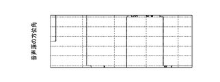
- FIG. 12 is a diagram showing the directivity (angle characteristic) when the beamformer and the sound source direction determination cancellation processing are combined. The solid line indicates the directivity of the beamformer.
- the modeling processing unit 58 includes a non-linear mapping processing unit 60, a linear filter 62, and a non-linear mapping processing unit 64.
- the modeling processing unit 58 generates a reference noise signal by performing a modeling process on the sine wave output from the fundamental wave determination unit 56.
- the reference noise signal output from the modeling processing unit 58 is a reference signal for removing noise from a signal including noise.
- the reference noise signal is input to a noise removal processing unit 66 provided in the post-processing unit 14.
- a signal including noise from the processing unit 12 is also input to the noise removal processing unit 66.
- the noise removal processing unit 66 removes noise from a signal including noise by using a reference noise signal and using a normalization least squares algorithm.
- the noise removal processing unit 66 outputs a signal from which noise has been removed.
- step S3 the direction of the voice source 72 that made the call is determined.
- the determination of the direction of the sound source 72 is performed by the sound source direction determination unit 16 and the like as described above.
- the directivity of the beamformer is set according to the direction of the sound source 72 (step S4).
- the setting of the beamformer directivity is performed by the adaptive algorithm determination unit 18, the processing unit 12, and the like as described above.
Abstract
This voice processing device comprises: a plurality of microphones 22 arranged in a vehicle; a voice source direction determination unit 16 that, when a voice source which is the source of a voice included in a sound reception signal acquired by each of the microphones is located in a near field, determines the direction of the voice source by treating the sound reception signal as a spherical wave, and, when the voice source is located in a far field, determines the direction of the voice source by treating the sound reception signal as a plane wave; and a beamforming processing unit 12 that performs beamforming so as to suppress sounds arriving from direction ranges outside the direction range including the direction of the voice source.
Description
本発明は、音声処理装置に関する。
The present invention relates to a voice processing device.
自動車等の車両には、様々な機器が設けられている。これらの様々な機器に対する操作は、例えば、操作ボタンや操作パネル等を操作することにより行われている。
Various devices are provided in vehicles such as automobiles. Operations on these various devices are performed, for example, by operating operation buttons, operation panels, and the like.
一方、近時では、音声認識の技術も提案されている(特許文献1~3)。
On the other hand, recently, voice recognition technology has also been proposed (Patent Documents 1 to 3).
しかしながら、車両においては、様々なノイズが存在する。このため、車両内で発せられる音声に対しての音声認識は容易ではなかった。
However, various noises exist in the vehicle. For this reason, it is not easy to recognize the voice generated in the vehicle.
本発明の目的は、音声認識の確実性を向上し得る良好な音声処理装置を提供することにある。
An object of the present invention is to provide a good speech processing apparatus capable of improving the certainty of speech recognition.
本発明の一観点によれば、車両に配された複数のマイクロフォンと、前記複数のマイクロフォンの各々によって取得される受音信号に含まれる音声の発生源である音声源が近傍界に位置する場合には、前記受音信号を球面波として扱って前記音声源の方位を判定し、前記音声源が前記遠方界に位置する場合には、前記受音信号を平面波として扱って前記音声源の方位を判定する音声源方位判定部と、前記音声源の前記方位を含む方位範囲以外の方位範囲から到来する音を抑圧するようにビームフォーミングを行うビームフォーミング処理部とを有することを特徴とする音声処理装置が提供される。
According to an aspect of the present invention, a plurality of microphones arranged in a vehicle and a sound source that is a sound source included in a sound reception signal acquired by each of the plurality of microphones is located in the near field. The sound reception signal is treated as a spherical wave to determine the direction of the sound source. When the sound source is located in the far field, the sound reception signal is treated as a plane wave and the direction of the sound source is determined. A sound source azimuth determining unit that determines the sound source, and a beam forming processing unit that performs beam forming so as to suppress sound coming from an azimuth range other than the azimuth range including the azimuth of the sound source. A processing device is provided.
本発明によれば、音声源が近傍界に位置する場合には、音声を球面波として扱うため、音声源が近傍界に位置する場合であっても、音声源の方位を高精度に判定することができる。音声源の方位を高精度に判定し得るため、本発明によれば、目的音以外の音を確実に抑制することができる。しかも、音声源が遠方界に位置する場合には、音声を平面波として扱って音声源の方位を判定するため、音声源の方位を判定するための処理負荷を軽くすることができる。従って、本発明によれば、音声認識の確実性を向上し得る良好な音声処理装置を提供することができる。
According to the present invention, since the sound is handled as a spherical wave when the sound source is located in the near field, the direction of the sound source is determined with high accuracy even when the sound source is located in the near field. be able to. Since the direction of the sound source can be determined with high accuracy, according to the present invention, sounds other than the target sound can be reliably suppressed. In addition, when the sound source is located in the far field, since the sound is handled as a plane wave and the direction of the sound source is determined, the processing load for determining the direction of the sound source can be reduced. Therefore, according to the present invention, it is possible to provide a good speech processing apparatus that can improve the certainty of speech recognition.
以下、本発明の実施の形態について図面を用いて説明する。なお、本発明は以下の実施形態に限定されるものではなく、その要旨を逸脱しない範囲において適宜変更可能である。また、以下で説明する図面において、同じ機能を有するものは同一の符号を付し、その説明を省略又は簡潔にすることもある。
Hereinafter, embodiments of the present invention will be described with reference to the drawings. In addition, this invention is not limited to the following embodiment, In the range which does not deviate from the summary, it can change suitably. In the drawings described below, components having the same function are denoted by the same reference numerals, and the description thereof may be omitted or simplified.
[一実施形態]
本発明の一実施形態による音声処理装置を図1乃至図17を用いて説明する。 [One Embodiment]
A speech processing apparatus according to an embodiment of the present invention will be described with reference to FIGS.
本発明の一実施形態による音声処理装置を図1乃至図17を用いて説明する。 [One Embodiment]
A speech processing apparatus according to an embodiment of the present invention will be described with reference to FIGS.
本実施形態による音声処理装置について説明するに先立って、車両の構成について図1を用いて説明する。図1は、車両の構成を示す概略図である。
Prior to describing the speech processing apparatus according to the present embodiment, the configuration of the vehicle will be described with reference to FIG. FIG. 1 is a schematic diagram showing a configuration of a vehicle.
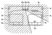
図1に示すように、車両(自動車)の車体(車室)46の前部には、運転者用の座席である運転席40と助手席者用の座席である助手席44とが配されている。運転席40は、例えば車室46の右側に位置している。運転席40の前方には、ステアリングホイール(ハンドル)78が配されている。助手席44は、例えば車室46の左側に位置している。運転席40と助手席44とにより、前部座席が構成されている。運転席40の近傍には、運転者が音声を発する場合における音声源72aが位置する。助手席44の近傍には、助手席者が音声を発する場合における音声源72bが位置する。運転者も助手席者も座席40,44に着座した状態で上半身を動かし得るため、音声源72の位置は変化し得る。車体46の後部には、後部座席70が配されている。なお、ここでは、個々の音声源を区別しないで説明する場合には、符号72を用い、個々の音声源を区別して説明する場合には、符号72a、72bを用いることとする。
As shown in FIG. 1, a driver's seat 40 that is a driver's seat and a passenger's seat 44 that is a passenger's seat are arranged at the front of a vehicle body (cabinet) 46 of a vehicle (automobile). ing. The driver's seat 40 is located on the right side of the passenger compartment 46, for example. A steering wheel (handle) 78 is disposed in front of the driver seat 40. The passenger seat 44 is located on the left side of the passenger compartment 46, for example. The driver seat 40 and the passenger seat 44 constitute a front seat. In the vicinity of the driver's seat 40, an audio source 72a when the driver emits audio is located. In the vicinity of the passenger seat 44, an audio source 72b when the passenger seat makes a sound is located. Since both the driver and the front passenger can move the upper body while seated in the seats 40 and 44, the position of the sound source 72 can change. A rear seat 70 is disposed at the rear of the vehicle body 46. Here, reference numeral 72 is used when the description is made without distinguishing between the individual sound sources, and reference numerals 72a and 72b are used when the description is made with the individual sound sources distinguished.
前部座席40,44の前方には、複数のマイクロフォン22(22a~22c)、即ち、マイクロフォンアレイが配されている。なお、ここでは、個々のマイクロフォンを区別しないで説明する場合には、符号22を用い、個々のマイクロフォンを区別して説明する場合には、符号22a~22cを用いることとする。マイクロフォン22は、ダッシュボード42に配されていてもよいし、ルーフに近い部位に配されていてもよい。
A plurality of microphones 22 (22a to 22c), that is, microphone arrays are arranged in front of the front seats 40 and 44. Here, reference numeral 22 is used when the description is made without distinguishing the individual microphones, and reference numerals 22a to 22c are used when the description is made with the individual microphones distinguished. The microphone 22 may be disposed on the dashboard 42 or may be disposed on a portion close to the roof.
前部座席40,44の音声源72とマイクロフォン22との間の距離は、数十cm程度である場合が多い。しかし、マイクロフォン22と音声源72との間の距離は、数十cmより小さくなることもあり得る。また、マイクロフォン22と音声源72との間の距離は、1mを超えることもあり得る。
The distance between the sound source 72 of the front seats 40 and 44 and the microphone 22 is often about several tens of centimeters. However, the distance between the microphone 22 and the audio source 72 can be less than a few tens of centimeters. Also, the distance between the microphone 22 and the audio source 72 can exceed 1 m.
車体46の内部には、車載音響機器(カーオーディオ機器)84(図2参照)のスピーカシステムを構成するスピーカ(ラウドスピーカ)76が配されている。スピーカ76から発せられる音楽(ミュージック)は、音声認識を行う上でのノイズとなり得る。
Inside the vehicle body 46, a speaker (loud speaker) 76 constituting a speaker system of an on-vehicle acoustic device (car audio device) 84 (see FIG. 2) is arranged. Music (music) emitted from the speaker 76 can be noise when performing speech recognition.
車体46には、車両を駆動するためのエンジン80が配されている。エンジン80から発せられる音は、音声認識を行う上でのノイズとなり得る。
The vehicle body 46 is provided with an engine 80 for driving the vehicle. The sound emitted from the engine 80 can be noise when performing speech recognition.
車両の走行中に路面の刺激によって車室46内に発生する騒音、即ち、ロードノイズも、音声認識を行う上でのノイズとなり得る。また、車両が走行する際に生ずる風切り音も、音声認識を行う上でのノイズ源となり得る。また、車体46の外部にも、ノイズ源82は存在し得る。外部ノイズ源82から発せられる音も、音声認識を行う上でのノイズとなり得る。
The noise generated in the passenger compartment 46 by the road surface stimulus during the traveling of the vehicle, that is, the road noise can also be a noise when performing voice recognition. In addition, wind noise generated when the vehicle travels can also be a noise source in performing speech recognition. Further, the noise source 82 may exist outside the vehicle body 46. The sound emitted from the external noise source 82 can also be noise in performing speech recognition.
車体46に配された様々な機器に対する操作を、音声による指示によって行い得ると便利である。音声による指示は、例えば図示しない自動音声認識装置を用いて認識される。本実施形態による音声処理装置は、音声認識の精度の向上に資するものである。
It is convenient if operations on various devices arranged on the vehicle body 46 can be performed by voice instructions. The voice instruction is recognized using, for example, an automatic voice recognition device (not shown). The speech processing apparatus according to the present embodiment contributes to improvement of speech recognition accuracy.
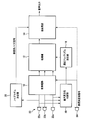
図2は、本実施形態による音声処理装置のシステム構成を示すブロック図である。
FIG. 2 is a block diagram showing a system configuration of the speech processing apparatus according to the present embodiment.
図2に示すように、本実施形態による音声処理装置は、前処理部10と、処理部12と、後処理部14と、音声源方位判定部16と、適応アルゴリズム決定部18と、ノイズモデル決定部20とを含む。
As shown in FIG. 2, the speech processing apparatus according to the present embodiment includes a pre-processing unit 10, a processing unit 12, a post-processing unit 14, a speech source direction determination unit 16, an adaptive algorithm determination unit 18, and a noise model. And a determination unit 20.
本実施形態による音声処理装置が更に図示しない自動音声認識装置を含んでいてもよいし、本実施形態による音声処理装置と自動音声認識装置とが別個の装置であってもよい。これらの構成要素と自動音声認識装置とを含む装置は、音声処理装置と称することもできるし、自動音声認識装置と称することもできる。
The voice processing device according to the present embodiment may further include an automatic voice recognition device (not shown), and the voice processing device and the automatic voice recognition device according to the present embodiment may be separate devices. An apparatus including these components and an automatic speech recognition apparatus can be referred to as a speech processing apparatus or an automatic speech recognition apparatus.
前処理部10には、複数のマイクロフォン22a~22cの各々によって取得される信号、即ち、受音信号が入力されるようになっている。マイクロフォン22としては、例えば、無指向性のマイクロフォンが用いられる。
A signal acquired by each of the plurality of microphones 22a to 22c, that is, a sound reception signal is input to the preprocessing unit 10. As the microphone 22, for example, an omnidirectional microphone is used.
図3A及び図3Bは、マイクロフォンの配置の例を示す概略図である。図3Aは、マイクロフォン22の数が3個の場合を示している。図3Bは、マイクロフォン22の数が2個の場合を示している。複数のマイクロフォン22は、直線上に位置するように配されている。
3A and 3B are schematic diagrams showing examples of microphone arrangement. FIG. 3A shows a case where the number of microphones 22 is three. FIG. 3B shows a case where the number of microphones 22 is two. The plurality of microphones 22 are arranged so as to be positioned on a straight line.
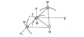
図4A及び図4Bは、音声源が遠方界に位置する場合と近傍界に位置する場合とを示す図である。図4Aは、音声源72が遠方界に位置する場合を示しており、図4Bは、音声源72が近傍界に位置する場合を示している。dは、音声源72からマイクロフォン22までの距離の差を示している。θは、音声源72の方位を示している。
4A and 4B are diagrams showing a case where the sound source is located in the far field and a case where the sound source is located in the near field. FIG. 4A shows a case where the audio source 72 is located in the far field, and FIG. 4B shows a case where the audio source 72 is located in the near field. d indicates a difference in distance from the sound source 72 to the microphone 22. θ represents the direction of the audio source 72.
図4Aに示すように、音声源72が遠方界に位置する場合には、マイクロフォン22に到達する音声は、平面波とみなすことができる。このため、本実施形態では、音声源72が遠方界に位置する場合には、マイクロフォン22に到達する音声を平面波として取り扱って、音声源72の方位(方向)、即ち、音源方位(DOA:Direction Of Arrival)を判定する。マイクロフォン22に到達する音声を平面波として扱うことが可能なため、音声源72が遠方界に位置する場合には、2個のマイクロフォン22を用いて音声源72の方位を判定し得る。なお、音声源72の位置やマイクロフォン22の配置によっては、マイクロフォン22の数が2個の場合であっても、近傍界に位置する音声源72の方位を判定し得る。
As shown in FIG. 4A, when the sound source 72 is located in the far field, the sound reaching the microphone 22 can be regarded as a plane wave. For this reason, in this embodiment, when the sound source 72 is located in the far field, the sound reaching the microphone 22 is handled as a plane wave, and the direction (direction) of the sound source 72, that is, the sound source direction (DOA: Direction) Of Arrival). Since the sound reaching the microphone 22 can be handled as a plane wave, when the sound source 72 is located in the far field, the direction of the sound source 72 can be determined using the two microphones 22. Depending on the position of the sound source 72 and the arrangement of the microphones 22, the orientation of the sound source 72 located in the near field can be determined even when the number of the microphones 22 is two.
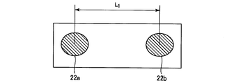
図4Bに示すように、音声源72が近傍界に位置する場合には、マイクロフォン22に到達する音声は、球面波とみなすことができる。このため、本実施形態では、音声源72が近傍界に位置する場合には、マイクロフォン22に到達する音声を球面波として扱って、音声源72の方位を判定する。マイクロフォン22に到達する音声を球面波として扱うことを要するため、音声源72が近傍界に位置する場合には、少なくとも3個のマイクロフォン22を用いて音声源72の方位を判定する。ここでは、説明の簡略化のため、マイクロフォン22の数を3個とする場合を例に説明する。
As shown in FIG. 4B, when the sound source 72 is located in the near field, the sound reaching the microphone 22 can be regarded as a spherical wave. For this reason, in this embodiment, when the sound source 72 is located in the near field, the sound reaching the microphone 22 is treated as a spherical wave, and the direction of the sound source 72 is determined. Since the sound reaching the microphone 22 needs to be handled as a spherical wave, when the sound source 72 is located in the near field, the orientation of the sound source 72 is determined using at least three microphones 22. Here, for simplification of description, a case where the number of microphones 22 is three will be described as an example.
マイクロフォン22aとマイクロフォン22bとの距離L1は、比較的長く設定されている。マイクロフォン22bとマイクロフォン22cとの距離L2は、比較的短く設定されている。
The distance L1 between the microphone 22a and the microphone 22b is set to be relatively long. The distance L2 between the microphone 22b and the microphone 22c is set to be relatively short.
本実施形態において距離L1と距離L2とを異ならせているのは、以下のような理由によるものである。即ち、本実施形態では、各々のマイクロフォン22に到達する音声(受音信号の到来時間差(TDOA:Time Delay Of Arrival)に基づいて、音声源72の方位を特定する。周波数が比較的低い音声は波長が比較的長いため、周波数が比較的低い音声に対応するためには、マイクロフォン22間の距離を比較的大きく設定することが好ましい。このため、本実施形態では、マイクロフォン22aとマイクロフォン22bとの間の距離L1を比較的長く設定している。一方、周波数が比較的高い音声は波長が比較的短いため、周波数が比較的高い音声に対応するためには、マイクロフォン22間の距離を比較的小さく設定することが好ましい。そこで、本実施形態では、マイクロフォン22bとマイクロフォン22cとの間の距離L2を比較的短く設定している。
The reason why the distance L1 and the distance L2 are different in the present embodiment is as follows. That is, in this embodiment, the direction of the sound source 72 is specified based on the sound (arrival time difference (TDOA: Time Delay Of Arrival) of the received sound signal) reaching each microphone 22. Since the wavelength is relatively long, it is preferable to set the distance between the microphones 22 to be relatively large in order to cope with the sound having a relatively low frequency.For this reason, in this embodiment, the microphone 22a and the microphone 22b The distance L1 between the microphones 22 is set to be relatively long, while the sound having a relatively high frequency has a relatively short wavelength, so that the distance between the microphones 22 is relatively small in order to correspond to the sound having a relatively high frequency. Therefore, in this embodiment, the distance L2 between the microphone 22b and the microphone 22c is relatively short. It is constant.
マイクロフォン22aとマイクロフォン22bとの間の距離L1は、例えば3400Hz以下の周波数の音声に対して好適とすべく、例えば5cm程度とする。マイクロフォン22bとマイクロフォン22cとの間の距離L2は、例えば3400Hzを超える周波数の音声に対して好適とすべく、例えば2.5cm程度とする。なお、距離L1、L2は、これらに限定されるものではなく、適宜設定し得る。
The distance L1 between the microphone 22a and the microphone 22b is, for example, about 5 cm so as to be suitable for sound having a frequency of 3400 Hz or less. The distance L2 between the microphone 22b and the microphone 22c is, for example, about 2.5 cm so as to be suitable for sound having a frequency exceeding 3400 Hz. The distances L1 and L2 are not limited to these, and can be set as appropriate.
本実施形態において、音声源72が遠方界に位置する場合に、マイクロフォン22に到達する音声を平面波として扱うのは、音声を平面波として扱う場合の方が、音声を球面波として扱う場合よりも、音声源72の方位を判定するための処理が簡略なためである。このため、本実施形態では、音声源72が遠方界に位置する場合には、マイクロフォン22に到達する音声を平面波として扱う。マイクロフォン22に到達する音声を平面波として扱うため、遠方界に位置する音声源72の方位を判定する際には、音声源72の方位を判定するための処理の負荷を軽くすることができる。
In the present embodiment, when the sound source 72 is located in the far field, the sound reaching the microphone 22 is handled as a plane wave when the sound is handled as a plane wave than when the sound is handled as a spherical wave. This is because the process for determining the direction of the audio source 72 is simple. For this reason, in this embodiment, when the sound source 72 is located in the far field, the sound reaching the microphone 22 is treated as a plane wave. Since the sound reaching the microphone 22 is handled as a plane wave, when determining the direction of the sound source 72 located in the far field, the processing load for determining the direction of the sound source 72 can be reduced.
なお、音声源72の方位を判定するための処理の付加は重くなるが、音声源72が近傍界に位置する場合には、マイクロフォン22に到達する音声を球面波として扱う。音声源72が近傍界に位置する場合には、マイクロフォン22に到達する音声を球面波として扱わないと、音声源72の方位を正確に判定し得ないためである。
In addition, although the addition of the process for determining the azimuth | direction of the audio | voice source 72 becomes heavy, when the audio | voice source 72 is located in a near field, the audio | voice which reaches | attains the microphone 22 is handled as a spherical wave. This is because when the sound source 72 is located in the near field, the direction of the sound source 72 cannot be accurately determined unless the sound reaching the microphone 22 is treated as a spherical wave.
このように、本実施形態では、音声源72が遠方界に位置する場合には、音声を平面波として扱って音声源72の方位を判定し、音声源72が近傍界に位置する場合には、音声を球面波として扱って音声源72の方位を判定する。
As described above, in the present embodiment, when the sound source 72 is located in the far field, the direction of the sound source 72 is determined by treating the sound as a plane wave, and when the sound source 72 is located in the near field, The direction of the sound source 72 is determined by treating the sound as a spherical wave.
図2に示すように、複数のマイクロフォン22によって取得される受音信号が、前処理部10に入力されるようになっている。前処理部10では、音場補正が行われる。音場補正においては、音響空間である車室46の音響特性を考慮したチューニングが行われる。
As shown in FIG. 2, sound reception signals acquired by the plurality of microphones 22 are input to the preprocessing unit 10. In the preprocessing unit 10, sound field correction is performed. In the sound field correction, tuning is performed in consideration of the acoustic characteristics of the vehicle compartment 46 that is an acoustic space.
マイクロフォン22によって取得される受音信号に音楽が含まれている場合には、前処理部10は、マイクロフォン22によって取得される受音信号から音楽を除去する。前処理部10には、参照用音楽信号(参照信号)が入力されるようになっている。前処理部10は、マイクロフォン22によって取得される受音信号に含まれている音楽を、参照用音楽信号を用いて除去する。
When the sound reception signal acquired by the microphone 22 includes music, the preprocessing unit 10 removes the music from the sound reception signal acquired by the microphone 22. A reference music signal (reference signal) is input to the preprocessing unit 10. The preprocessing unit 10 removes music included in the sound reception signal acquired by the microphone 22 using the reference music signal.
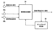
図5は、音楽の除去のアルゴリズムを示す概略図である。車載音響機器84によって音楽が再生されている際には、マイクロフォン22によって取得される受音信号には音楽が含まれる。マイクロフォン22によって取得される音楽を含む受音信号は、前処理部10内に設けられた音楽除去処理部24に入力されるようになっている。また、参照用音楽信号が、音楽除去処理部24に入力されるようになっている。参照用音楽信号は、例えば、車載音響機器84のスピーカ76から出力された音楽を、マイクロフォン26a、26bによって取得することにより得ることが可能である。また、スピーカ76によって音に変換される前の音楽ソース信号を、参照用音楽信号として、音楽除去処理部24に入力するようにしてもよい。
FIG. 5 is a schematic diagram showing a music removal algorithm. When music is played back by the in-vehicle acoustic device 84, the sound reception signal acquired by the microphone 22 includes music. A received sound signal including music acquired by the microphone 22 is input to a music removal processing unit 24 provided in the preprocessing unit 10. A reference music signal is input to the music removal processing unit 24. The reference music signal can be obtained, for example, by acquiring music output from the speaker 76 of the in-vehicle acoustic device 84 using the microphones 26a and 26b. Alternatively, the music source signal before being converted into sound by the speaker 76 may be input to the music removal processing unit 24 as a reference music signal.
音楽除去処理部24からの出力信号は、前処理部10内に設けられたステップサイズ判定部28に入力されるようになっている。ステップサイズ判定部28は、音楽除去処理部24の出力信号のステップサイズの判定を行うものである。ステップサイズ判定部28によって判定されたステップサイズは、音楽除去処理部24にフィードバックされるようになっている。音楽除去処理部24は、参照用音楽信号を用い、ステップサイズ判定部28により判定されたステップサイズに基づき、周波数領域の正規化最小二乗法(NLMS:Normalized Least-Mean Square)のアルゴリズムによって、音楽を含む信号から音楽を除去する。車室46内における音楽の反響成分をも十分に除去すべく、十分な処理段数で音楽の除去の処理が行われる。
The output signal from the music removal processing unit 24 is input to a step size determination unit 28 provided in the preprocessing unit 10. The step size determination unit 28 determines the step size of the output signal of the music removal processing unit 24. The step size determined by the step size determination unit 28 is fed back to the music removal processing unit 24. The music removal processing unit 24 uses the reference music signal and, based on the step size determined by the step size determination unit 28, the frequency domain normalized least square method (NLMS: Normalized Least-Mean Square) algorithm Remove music from signals that contain. The music removal process is performed with a sufficient number of processing steps to sufficiently remove the reverberant component of the music in the passenger compartment 46.
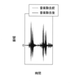
図6は、音楽の除去前と除去後の信号波形を示す図である。横軸は時間を示しており、縦軸は振幅を示している。グレーで示した信号は音楽の除去前を示しており、ブラックで示した信号は音楽の除去後を示している。図6から分かるように、音楽が確実に除去されている。
FIG. 6 is a diagram showing signal waveforms before and after music removal. The horizontal axis indicates time, and the vertical axis indicates amplitude. The signal shown in gray shows before music removal, and the signal shown in black shows after music removal. As can be seen from FIG. 6, the music has been reliably removed.
このようにして音楽が除去された信号が、前処理部10の音楽除去処理部24から出力され、処理部12に入力される。なお、前処理部10において音楽を十分に除去し得ない場合には、後処理部14においても、音楽の除去の処理を行うようにしてもよい。
The signal from which music has been removed in this way is output from the music removal processing unit 24 of the preprocessing unit 10 and input to the processing unit 12. If the pre-processing unit 10 cannot sufficiently remove music, the post-processing unit 14 may also perform music removal processing.
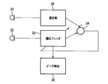
音声源方位判定部16では、音声源の方位の判定が行われる。図7は、音声源の方位の判定のアルゴリズムを示す図である。複数のマイクロフォン22のうちのあるマイクロフォン22からの信号が、音声源方位判定部16内に設けられた遅延部30に入力されるようになっている。複数のマイクロフォン22のうちの他のマイクロフォン22からの信号が、音声源方位判定部16内に設けられた適応フィルタ32に入力されるようになっている。遅延部30の出力信号と適応フィルタ32の出力信号とが、減算点34に入力されるようになっている。減算点34においては、遅延部30の出力信号から適応フィルタ34の出力信号が減算される。減算点34において減算処理が行われた信号に基づいて、適応フィルタ32が調整される。適応フィルタ32からの出力は、ピーク検出部36に入力されるようになっている。ピーク検出部36は、適応フィルタ係数のピーク(最大値)を検出するものである。適応フィルタ係数のピークに対応する到来時間差τが、目的音の到来方位に対応する到来時間差τである。従って、こうして求められた到来時間差τに基づいて、音声源72の方位、即ち、目的音の到来方位を判定することが可能となる。
The sound source direction determination unit 16 determines the direction of the sound source. FIG. 7 is a diagram showing an algorithm for determining the direction of the sound source. A signal from a certain microphone 22 among the plurality of microphones 22 is input to a delay unit 30 provided in the sound source direction determination unit 16. A signal from another microphone 22 among the plurality of microphones 22 is input to an adaptive filter 32 provided in the sound source direction determination unit 16. The output signal of the delay unit 30 and the output signal of the adaptive filter 32 are input to the subtraction point 34. At the subtraction point 34, the output signal of the adaptive filter 34 is subtracted from the output signal of the delay unit 30. The adaptive filter 32 is adjusted based on the signal subjected to the subtraction process at the subtraction point 34. The output from the adaptive filter 32 is input to the peak detector 36. The peak detector 36 detects a peak (maximum value) of the adaptive filter coefficient. The arrival time difference τ corresponding to the peak of the adaptive filter coefficient is the arrival time difference τ corresponding to the arrival direction of the target sound. Therefore, it is possible to determine the direction of the voice source 72, that is, the direction of arrival of the target sound, based on the arrival time difference τ thus obtained.
音の速度をc[m/s]、マイクロフォン間の距離をd[m]、到来時間差をτ[秒]とすると、音声源72の方向θ[度]は、以下のような式(1)によって表される。なお、音速cは、340[m/s]程度である。
Assuming that the speed of sound is c [m / s], the distance between microphones is d [m], and the arrival time difference is τ [seconds], the direction θ [degree] of the sound source 72 is expressed by the following equation (1). Represented by The sound speed c is about 340 [m / s].
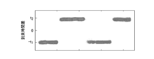
図8Aは、適応フィルタ係数を示す図である。図8Bは、音声源の方位角を示す図である。図8Cは、音声信号の振幅を示す図である。図8Aでは、適応フィルタ係数がピークとなる部分にハッチングを付している。図8Bは、到来時間差τに基づいて判定された音声源72の方位を示している。図8Cは、音声信号の振幅を示している。なお、図8A~図8Cは、運転者と助手席者とで交互に音声を発した場合を示している。ここでは、運転者が音声を発する場合の音声源72aの方位は、α1とした。助手席者が音声を発する場合の音声源72bの方位は、α2とした。
FIG. 8A is a diagram showing adaptive filter coefficients. FIG. 8B is a diagram showing the azimuth angle of the audio source. FIG. 8C is a diagram illustrating the amplitude of the audio signal. In FIG. 8A, the portion where the adaptive filter coefficient has a peak is hatched. FIG. 8B shows the orientation of the sound source 72 determined based on the arrival time difference τ. FIG. 8C shows the amplitude of the audio signal. 8A to 8C show the case where the driver and the passenger are uttered alternately. Here, the direction of the sound source 72a when the driver emits sound is α1. The direction of the sound source 72b when the passenger seat utters sound is α2.
図8Aに示すように、適応フィルタ係数w(t,τ)のピークに基づいて、到来時間差τを検出することが可能である。運転者が音声を発した場合には、適応フィルタ係数のピークに対応する到来時間差τは、例えば-t1程度となる。そして、到来時間差τに基づいて音声源72aの方位角を判定すると、音声源72aの方位角は例えばα1程度と判定される。一方、助手席者が音声を発した場合には、適応フィルタ係数のピークに対応する到来時間差τは、例えばt2程度となる。そして、到来時間差τに基づいて音声源72bの方位角を判定すると、音声源72bの方位角は例えばα2度程度と判定される。なお、ここでは、α1の方位に運転者が位置しており、α2の方位に助手席者が位置している場合を例に説明したが、これに限定されるものではない。音声源72が近傍界に位置する場合であっても、音声源72が遠方界に位置する場合であっても、到来時間差τに基づいて、音声源72の位置を特定することが可能である。但し、音声源72が近傍界に位置する場合には、上述したように、マイクロフォン22が3個以上必要であるため、音声源72の方位を求めるための処理の負荷は重くなる。
As shown in FIG. 8A, it is possible to detect the arrival time difference τ based on the peak of the adaptive filter coefficient w (t, τ). When the driver utters voice, the arrival time difference τ corresponding to the peak of the adaptive filter coefficient is, for example, about −t1. When the azimuth angle of the audio source 72a is determined based on the arrival time difference τ, the azimuth angle of the audio source 72a is determined to be about α1, for example. On the other hand, when the passenger seat utters a voice, the arrival time difference τ corresponding to the peak of the adaptive filter coefficient is, for example, about t2. When the azimuth angle of the audio source 72b is determined based on the arrival time difference τ, the azimuth angle of the audio source 72b is determined to be about α2 degrees, for example. Here, the case where the driver is located in the direction of α1 and the passenger seat is located in the direction of α2 has been described as an example, but the present invention is not limited to this. Whether the audio source 72 is located in the near field or the audio source 72 is located in the far field, the position of the audio source 72 can be specified based on the arrival time difference τ. . However, when the sound source 72 is located in the near field, as described above, three or more microphones 22 are required, so that the processing load for obtaining the direction of the sound source 72 becomes heavy.
音声源方位判定部16の出力信号、即ち、音声源72の方位を示す信号が、適応アルゴリズム決定部18に入力されるようになっている。適応アルゴリズム決定部18は、音声源72の方位に基づいて適応アルゴリズムを決定するものである。適応アルゴリズム決定部18によって決定された適応アルゴリズムを示す信号が、適応アルゴリズム決定部18から処理部12に入力されるようになっている。
The output signal of the voice source direction determination unit 16, that is, the signal indicating the direction of the voice source 72 is input to the adaptive algorithm determination unit 18. The adaptive algorithm determination unit 18 determines an adaptive algorithm based on the orientation of the audio source 72. A signal indicating the adaptation algorithm determined by the adaptation algorithm determination unit 18 is input from the adaptation algorithm determination unit 18 to the processing unit 12.
処理部12は、適応的に指向性を形成する信号処理である適応ビームフォーミングを行うものである(適応ビームフォーマ)。ビームフォーマとしては、例えばFrostビームフォーマを用いることができる。なお、ビームフォーミングは、Frostビームフォーマに限定されるものではなく、様々なビームフォーマを適宜適用することができる。処理部12は、適応アルゴリズム決定部18によって決定された適応アルゴリズムに基づいて、ビームフォーミングを行う。本実施形態において、ビームフォーミングを行うのは、目的音の到来方位に対しての感度を確保しつつ、目的音の到来方向以外の感度を低下させるためである。目的音は、例えば運転者から発せられる音声である。運転者は運転席40に着座した状態で上半身を動かし得るため、音声源72aの位置は変化し得る。音声源72aの位置の変化に応じて、目的音の到来方位は変化する。良好な音声認識を行うためには、目的音の到来方向以外の感度を確実に低下させることが好ましい。そこで、本実施形態では、上記のようにして判定される音声源72の方位に基づいて、当該方位を含む方位範囲以外の方位範囲からの音声を抑圧すべく、ビームフォーマを順次更新する。
The processing unit 12 performs adaptive beamforming, which is signal processing that adaptively forms directivity (adaptive beamformer). For example, a Frost beamformer can be used as the beamformer. The beam forming is not limited to the Frost beamformer, and various beamformers can be applied as appropriate. The processing unit 12 performs beam forming based on the adaptive algorithm determined by the adaptive algorithm determination unit 18. In this embodiment, the beam forming is performed in order to reduce the sensitivity other than the arrival direction of the target sound while securing the sensitivity to the arrival direction of the target sound. The target sound is, for example, a sound emitted from the driver. Since the driver can move the upper body while sitting in the driver's seat 40, the position of the sound source 72a can change. The arrival direction of the target sound changes according to the change in the position of the sound source 72a. In order to perform good speech recognition, it is preferable to reliably reduce the sensitivity other than the arrival direction of the target sound. Therefore, in the present embodiment, based on the direction of the sound source 72 determined as described above, the beam former is sequentially updated so as to suppress sound from an azimuth range other than the azimuth range including the azimuth.
図9は、ビームフォーマの指向性を概念的に示す図である。図9は、音声認識の対象とすべき音声源72aが運転席40に位置している場合のビームフォーマの指向性を概念的に示している。図9におけるハッチングは、到来音が抑圧(抑制、低減)される方位範囲を示している。図9に示すように、運転席40の方位を含む方位範囲以外の方位範囲から到来する音が抑圧される。
FIG. 9 is a diagram conceptually showing the directivity of the beamformer. FIG. 9 conceptually shows the directivity of the beamformer when the voice source 72a to be subjected to voice recognition is located in the driver's seat 40. The hatching in FIG. 9 indicates the azimuth range in which the incoming sound is suppressed (suppressed or reduced). As shown in FIG. 9, sound coming from an azimuth range other than the azimuth range including the azimuth of the driver's seat 40 is suppressed.
なお、音声認識の対象とすべき音声源72bが助手席44に位置している場合には、助手席44の方位を含む方位範囲以外の方位範囲から到来する音が抑圧されるようにすればよい。
If the voice source 72b to be subjected to voice recognition is located in the passenger seat 44, sound coming from an azimuth range other than the azimuth range including the azimuth of the passenger seat 44 is suppressed. Good.
図10は、ビームフォーマのアルゴリズムを示す図である。マイクロフォン22a~22cによって取得される受音信号が、前処理部10(図2参照)を介して、処理部12内に設けられた窓関数/高速フーリエ変換処理部48a~48cにそれぞれ入力されるようになっている。窓関数/高速フーリエ変換処理部48a~48cは、窓関数処理及び高速フーリエ変換処理を行うものである。本実施形態において、窓関数処理及び高速フーリエ変換処理を行うのは、周波数領域での計算は時間領域での計算より速いためである。窓関数/高速フーリエ変換処理部48aの出力信号X1,kとビームフォーマの重みテンソルW1,k
*とが、乗算点50aにおいて乗算されるようになっている。窓関数/高速フーリエ変換処理部48bの出力信号X2,kとビームフォーマの重みテンソルW2,k
*とが、乗算点50bにおいて乗算されるようになっている。窓関数/高速フーリエ変換処理部48cの出力信号X3,kとビームフォーマの重みテンソルW3,k
*とが、乗算点50cにおいて乗算されるようになっている。乗算点50a~50cにおいてそれぞれ乗算処理された信号が、加算点52において加算されるようになっている。加算点52において加算処理された信号Ykは、処理部12内に設けられた逆高速フーリエ変換/重畳加算処理部54に入力されるようになっている。逆高速フーリエ変換/重畳加算処理部54は、逆高速フーリエ変換処理及び重畳加算(OLA:OverLap-Add)法による処理を行うものである。重畳加算法による処理を行うことにより、周波数領域の信号が時間領域の信号に戻される。逆高速フーリエ変換処理及び重畳加算法による処理が行われた信号が、逆高速フーリエ変換/重畳加算処理部54から後処理部14に入力されるようになっている。
FIG. 10 is a diagram showing a beamformer algorithm. The received sound signals acquired by the microphones 22a to 22c are input to the window function / fast Fourier transform processing units 48a to 48c provided in the processing unit 12 via the preprocessing unit 10 (see FIG. 2). It is like that. The window function / fast Fourier transform processing units 48a to 48c perform window function processing and fast Fourier transform processing. In this embodiment, the window function process and the fast Fourier transform process are performed because the calculation in the frequency domain is faster than the calculation in the time domain. The output signal X1 , k of the window function / fast Fourier transform processing unit 48a and the beamformer weight tensor W1 , k * are multiplied at the multiplication point 50a. The output signal X2 , k of the window function / fast Fourier transform processor 48b and the beamformer weight tensor W2 , k * are multiplied at the multiplication point 50b. The output signal X 3, k of the window function / fast Fourier transform processing unit 48c and the beamformer weight tensor W 3, k * are multiplied at the multiplication point 50c. The signals multiplied at the multiplication points 50 a to 50 c are added at the addition point 52. The signal Y k added at the addition point 52 is input to an inverse fast Fourier transform / superimposition addition processing unit 54 provided in the processing unit 12. The inverse fast Fourier transform / superimposition addition processing unit 54 performs an inverse fast Fourier transform process and a process based on an overlay addition (OLA: OverLap-Add) method. By performing processing by the superposition addition method, the frequency domain signal is returned to the time domain signal. A signal subjected to the inverse fast Fourier transform process and the superposition addition method is input from the inverse fast Fourier transform / superimposition addition processing unit 54 to the post-processing unit 14.
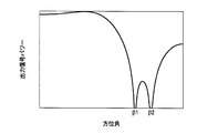
図11は、ビームフォーマにより得られた指向性(角度特性)を示す図である。横軸は方位角を示しており、縦軸は出力信号パワーを示している。図11から分かるように、例えば方位角β1と方位角β2とにおいて出力信号パワーが極小となる。方位角β1と方位角β2との間においても、十分な抑圧が行われている。図11に示すような指向性のビームフォーマを用いれば、助手席から到来する音を十分に抑圧することができる。一方、運転席から到来する音声は、殆ど抑圧されることなくマイクロフォン22に到達する。
FIG. 11 is a diagram showing the directivity (angle characteristic) obtained by the beamformer. The horizontal axis indicates the azimuth angle, and the vertical axis indicates the output signal power. As can be seen from FIG. 11, for example, the output signal power is minimized at the azimuth angle β1 and the azimuth angle β2. Sufficient suppression is also performed between the azimuth angle β1 and the azimuth angle β2. If a directional beamformer as shown in FIG. 11 is used, the sound coming from the passenger seat can be sufficiently suppressed. On the other hand, the voice coming from the driver's seat reaches the microphone 22 with almost no suppression.
本実施形態では、音声源72から到来する音声の大きさよりも、音声源72の方位を含む方位範囲以外の方位範囲から到来する音の方が大きい場合には、音声源72の方位の判定を中断する(音声源方位判定キャンセル処理)。例えば、運転者からの音声を取得するようにビームフォーマが設定されている場合において、運転者からの音声よりも助手席者からの音声の方が大きい場合には、音声源の方位の推定を中断する。この場合、マイクロフォン22によって取得される受音信号を十分に抑圧する。図12は、ビームフォーマと音声源方位判定キャンセル処理とを組み合わせた場合の指向性(角度特性)を示す図である。実線は、ビームフォーマの指向性を示している。一点鎖線は、音声源方位判定キャンセル処理の角度特性を示している。例えばγ1より小さい方位から到来する音声、又は、例えばγ2より大きい方位から到来する音声が、運転者からの音声よりも大きい場合には、音声源方位判定キャンセル処理が行われる。なお、ここでは、運転者からの音声を取得するようにビームフォーマが設定されている場合を例に説明したが、助手席者からの音声を取得するようにビームフォーマが設定されていてもよい。この場合には、助手席者からの音声よりも運転者からの音声の方が大きい場合には、音声源の方位の推定を中断する。
In the present embodiment, when the sound coming from an azimuth range other than the azimuth range including the azimuth of the audio source 72 is larger than the magnitude of the audio coming from the audio source 72, the direction of the audio source 72 is determined. Suspend (voice source direction determination cancellation process). For example, when the beamformer is set to acquire the voice from the driver, if the voice from the passenger seat is larger than the voice from the driver, the direction of the voice source is estimated. Interrupt. In this case, the sound reception signal acquired by the microphone 22 is sufficiently suppressed. FIG. 12 is a diagram showing the directivity (angle characteristic) when the beamformer and the sound source direction determination cancellation processing are combined. The solid line indicates the directivity of the beamformer. The alternate long and short dash line indicates the angle characteristic of the audio source direction determination cancellation process. For example, when a voice arriving from a direction smaller than γ1 or a voice arriving from a direction larger than γ2, for example, is larger than the voice from the driver, a voice source direction determination canceling process is performed. Here, the case where the beamformer is set so as to acquire the voice from the driver has been described as an example, but the beamformer may be set so as to acquire the voice from the passenger. . In this case, when the voice from the driver is louder than the voice from the passenger, the estimation of the direction of the voice source is interrupted.
図13は、マイクロフォンが2個の場合におけるビームフォーマにより得られる指向性を示すグラフである。横軸は方位角であり、縦軸は出力信号パワーである。マイクロフォン22が2個であるため、極小値となる角度が1箇所のみである。図13から分かるように、例えば方位角β1においては著しい抑圧が可能であるが、音声源72の方位の変化に対するロバスト性はあまり高くない。
FIG. 13 is a graph showing the directivity obtained by the beamformer when there are two microphones. The horizontal axis is the azimuth angle, and the vertical axis is the output signal power. Since there are two microphones 22, there is only one angle at which the minimum value is obtained. As can be seen from FIG. 13, for example, significant suppression is possible at the azimuth angle β1, but the robustness to changes in the azimuth of the audio source 72 is not very high.
こうして、音声源72の方位を含む方位範囲以外の方位範囲から到来する音が抑圧された信号が、処理部12から出力される。処理部12からの出力信号は、後処理部14に入力されるようになっている。
Thus, a signal in which sound coming from an azimuth range other than the azimuth range including the azimuth of the audio source 72 is suppressed is output from the processing unit 12. An output signal from the processing unit 12 is input to the post-processing unit 14.
後処理部(後処理適応フィルタ)14においては、ノイズの除去が行われる。かかるノイズとしては、例えばエンジンノイズ、ロードノイズ、風切り音等が挙げられる。図14は、ノイズの除去のアルゴリズムを示す図である。ノイズモデル決定部20内に設けられた基本波判定部56によって、ノイズの基本波が判定される。基本波判定部56は、ノイズの基本波に基づいた正弦波を出力する。基本波判定部56から出力される正弦波は、ノイズモデル決定部20内に設けられたモデリング処理部58に入力されるようになっている。モデリング処理部58は、非線形マッピング処理部60と、線形フィルタ62と、非線形マッピング処理部64とを有している。モデリング処理部58は、Hammerstein-Wiener非線形モデルによるモデリング処理を行うものである。モデリング処理部58には、非線形マッピング処理部60、線形フィルタ62及び非線形マッピング処理部64が設けられている。モデリング処理部58は、基本波判定部56から出力される正弦波に対してモデリング処理を行うことにより、参照用ノイズ信号を生成する。モデリング処理部58から出力される参照用ノイズ信号は、ノイズが含まれた信号からノイズを除去するための参照信号となる。参照用ノイズ信号は、後処理部14内に設けられたノイズ除去処理部66に入力されるようになっている。ノイズ除去処理部66には、処理部12からのノイズを含む信号も入力されるようになっている。ノイズ除去処理部66は、参照用ノイズ信号を用い、正規化最小二乗法のアルゴリズムによって、ノイズを含む信号からノイズを除去する。ノイズ除去処理部66からは、ノイズが除去された信号が出力される。
In the post-processing unit (post-processing adaptive filter) 14, noise is removed. Examples of such noise include engine noise, road noise, and wind noise. FIG. 14 is a diagram illustrating an algorithm for noise removal. A fundamental wave of noise is determined by a fundamental wave determination unit 56 provided in the noise model determination unit 20. The fundamental wave determination unit 56 outputs a sine wave based on the fundamental wave of noise. The sine wave output from the fundamental wave determination unit 56 is input to a modeling processing unit 58 provided in the noise model determination unit 20. The modeling processing unit 58 includes a non-linear mapping processing unit 60, a linear filter 62, and a non-linear mapping processing unit 64. The modeling processing unit 58 performs modeling processing using a Hammerstein-Wiener nonlinear model. The modeling processing unit 58 includes a non-linear mapping processing unit 60, a linear filter 62, and a non-linear mapping processing unit 64. The modeling processing unit 58 generates a reference noise signal by performing a modeling process on the sine wave output from the fundamental wave determination unit 56. The reference noise signal output from the modeling processing unit 58 is a reference signal for removing noise from a signal including noise. The reference noise signal is input to a noise removal processing unit 66 provided in the post-processing unit 14. A signal including noise from the processing unit 12 is also input to the noise removal processing unit 66. The noise removal processing unit 66 removes noise from a signal including noise by using a reference noise signal and using a normalization least squares algorithm. The noise removal processing unit 66 outputs a signal from which noise has been removed.
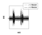
図15は、ノイズの除去前と除去後の信号波形を示す図である。横軸は時間を示しており、縦軸は振幅を示している。グレーで示した信号はノイズ除去前を示しており、ブラックで示した信号はノイズ除去後を示している。図15から分かるように、ノイズが確実に除去されている。
FIG. 15 shows signal waveforms before and after noise removal. The horizontal axis indicates time, and the vertical axis indicates amplitude. The signal shown in gray shows before noise removal, and the signal shown in black shows after noise removal. As can be seen from FIG. 15, noise is reliably removed.
後処理部14においては、歪低減処理も行われる。なお、ノイズの除去は、後処理部14においてのみ行われるわけではない。マイクロフォン22を介して取得された音に対して、前処理部10、処理部12及び後処理部14において行われる一連の処理によって、ノイズの除去が行われる。
In the post-processing unit 14, distortion reduction processing is also performed. Note that noise removal is not performed only in the post-processing unit 14. Noise is removed from a sound acquired via the microphone 22 by a series of processes performed in the preprocessing unit 10, the processing unit 12, and the postprocessing unit 14.
こうして、後処理部14によって後処理が行われた信号が、図示しない自動音声認識装置に音声出力として出力される。目的音以外の音が抑圧された良好な目的音が自動音声認識装置に入力されるため、自動音声認識装置は、音声認識の精度を向上することができる。自動音声認識装置による音声認識結果に基づいて、車両に搭載されている機器等に対しての操作が自動で行われる。
Thus, the signal that has been post-processed by the post-processing unit 14 is output as a voice output to an automatic voice recognition device (not shown). Since a good target sound in which sounds other than the target sound are suppressed is input to the automatic speech recognition device, the automatic speech recognition device can improve the accuracy of speech recognition. Based on the voice recognition result by the automatic voice recognition device, the operation on the device mounted on the vehicle is automatically performed.
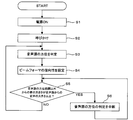
次に、本実施形態による音声処理装置の動作について図17を用いて説明する。図17は、本実施形態による音声処理装置の動作を示すフローチャートである。
Next, the operation of the speech processing apparatus according to the present embodiment will be described with reference to FIG. FIG. 17 is a flowchart showing the operation of the speech processing apparatus according to the present embodiment.
まず、音声処理装置の電源がONにされる(ステップS1)。
First, the power of the speech processing apparatus is turned on (step S1).
次に、乗員による呼びかけが音声処理装置に対して行われる(ステップS2)。かかる呼びかけによって、音声処理が開始される。ここでは、例えば、運転者によって呼びかけが行われる場合を例に説明する。なお、呼びかけは、運転者が行わなくてもよい。例えば、助手席者が呼びかけを行ってもよい。また、呼びかけは、特定の言葉であってもよいし、単なる発声であってもよい。
Next, a call by the occupant is made to the voice processing device (step S2). With such a call, voice processing is started. Here, for example, a case where a call is made by a driver will be described as an example. The call may not be performed by the driver. For example, a passenger seat may make a call. The call may be a specific word or a simple utterance.
次に、呼びかけを行った音声源72の方位が判定される(ステップS3)。音声源72の方位の判定は、上述したように、音声源方位判定部16等によって行われる。
Next, the direction of the voice source 72 that made the call is determined (step S3). The determination of the direction of the sound source 72 is performed by the sound source direction determination unit 16 and the like as described above.
次に、音声源72の方位に応じて、ビームフォーマの指向性を設定する(ステップS4)。ビームフォーマの指向性の設定は、上述したように、適応アルゴリズム決定部18、処理部12等によって行われる。
Next, the directivity of the beamformer is set according to the direction of the sound source 72 (step S4). The setting of the beamformer directivity is performed by the adaptive algorithm determination unit 18, the processing unit 12, and the like as described above.
音声源72の方位を含む所定の方位範囲以外の方位範囲から到来する音の大きさが、音声源72から到来する音声の大きさ以上である場合には(ステップS5においてYES)、音声源72の判定を中断する(ステップS6)。
When the magnitude of sound coming from an azimuth range other than the predetermined azimuth range including the azimuth of voice source 72 is greater than or equal to the magnitude of voice coming from voice source 72 (YES in step S5), voice source 72 Is interrupted (step S6).
一方、音声源72の方位を含む所定の方位範囲以外の方位範囲から到来する音の大きさが、音声源72から到来する音声の大きさ以上でない場合には(ステップS5においてNO)、ステップS3、S4を繰り返し行う。
On the other hand, if the magnitude of sound coming from an azimuth range other than the predetermined azimuth range including the azimuth of voice source 72 is not greater than the magnitude of voice coming from voice source 72 (NO in step S5), step S3 , S4 is repeated.
こうして、音声源72の位置の変化に応じて、ビームフォーマが適応的に設定され、目的音以外の音が確実に抑制される。
Thus, the beamformer is adaptively set according to the change of the position of the sound source 72, and the sound other than the target sound is surely suppressed.
このように、本実施形態によれば、音声源72が近傍界に位置する場合には、音声を球面波として扱うため、音声源72が近傍界に位置する場合であっても、音声源72の方位を高精度に判定することができる。音声源72の方位を高精度に判定し得るため、本実施形態によれば、目的音以外の音を確実に抑制することができる。しかも、音声源72が遠方界に位置する場合には、音声を平面波として扱って音声源72の方位を判定するため、音声源72の方位を判定するための処理負荷を軽くすることができる。従って、本実施形態によれば、音声認識の確実性を向上し得る良好な音声処理装置を提供することができる。
As described above, according to the present embodiment, when the sound source 72 is located in the near field, the sound is handled as a spherical wave. Therefore, even if the sound source 72 is located in the near field, the sound source 72 is treated. Can be determined with high accuracy. Since the direction of the sound source 72 can be determined with high accuracy, according to the present embodiment, it is possible to reliably suppress sounds other than the target sound. In addition, when the sound source 72 is located in the far field, since the sound is handled as a plane wave and the direction of the sound source 72 is determined, the processing load for determining the direction of the sound source 72 can be reduced. Therefore, according to the present embodiment, it is possible to provide a good speech processing apparatus that can improve the certainty of speech recognition.
また、本実施形態によれば、受音信号に含まれる音楽を除去する音楽除去処理部24が設けられているため、車載音響機器84から音楽が再生されている場合であっても、良好な音声認識を行うことが可能となる。
In addition, according to the present embodiment, since the music removal processing unit 24 that removes music included in the received sound signal is provided, even when music is played from the in-vehicle acoustic device 84, it is satisfactory. Voice recognition can be performed.
また、本実施形態によれば、受音信号に含まれるノイズを除去するノイズ除去処理部66が設けられているため、車両が走行中であっても、良好な音声認識を行うことが可能となる。
In addition, according to the present embodiment, since the noise removal processing unit 66 that removes noise included in the received sound signal is provided, it is possible to perform good voice recognition even when the vehicle is traveling. Become.
[変形実施形態]
上記実施形態に限らず種々の変形が可能である。 [Modified Embodiment]
The present invention is not limited to the above embodiment, and various modifications are possible.
上記実施形態に限らず種々の変形が可能である。 [Modified Embodiment]
The present invention is not limited to the above embodiment, and various modifications are possible.
例えば、上記実施形態では、マイクロフォン22の数が3個である場合を例に説明したが、マイクロフォン22の数は3個に限定されるものではなく、4個以上であってもよい。多くのマイクロフォン22を用いれば、音声源72の方位をより高精度に判定し得る。
For example, in the above embodiment, the case where the number of the microphones 22 is three has been described as an example, but the number of the microphones 22 is not limited to three, and may be four or more. If many microphones 22 are used, the direction of the sound source 72 can be determined with higher accuracy.
また、上記実施形態では、本実施形態による音声処理装置の出力が自動音声認識装置に入力される場合、即ち、本実施形態による音声処理装置の出力が音声認識に用いられる場合を例に説明したが、これに限定されるものではない。本実施形態による音声処理装置の出力が、自動音声認識に用いられなくてもよい。例えば、本実施形態による音声処理装置を、電話での会話における音声処理に適用してもよい。具体的には、本実施形態による音声処理装置を用いて目的音以外の音を抑圧し、良好な音声を送信するようにしてもよい。本実施形態による音声処理装置を電話での会話に適用すれば、良好な音声での通話を実現することができる。
In the above embodiment, the case where the output of the speech processing apparatus according to the present embodiment is input to the automatic speech recognition apparatus, that is, the case where the output of the speech processing apparatus according to the present embodiment is used for speech recognition has been described as an example. However, the present invention is not limited to this. The output of the speech processing apparatus according to the present embodiment may not be used for automatic speech recognition. For example, the voice processing device according to the present embodiment may be applied to voice processing in a telephone conversation. Specifically, the sound processing apparatus according to the present embodiment may be used to suppress sounds other than the target sound and transmit good sound. If the voice processing device according to the present embodiment is applied to telephone conversation, it is possible to realize a voice conversation.
この出願は2014年12月26日に出願された日本国特許出願第2014-263918号からの優先権を主張するものであり、その内容を引用してこの出願の一部とするものである。
This application claims priority from Japanese Patent Application No. 2014-263918 filed on Dec. 26, 2014, the contents of which are incorporated herein by reference.
22,22a~22c…マイクロフォン
40…運転席
42…ダッシュボード
44…助手席
46…車体
72、72a、72b…音声源
76…スピーカ
78…ステアリングホイール
80…エンジン
82…外部ノイズ源
84…車載音響機器 22, 22a to 22c ...Microphone 40 ... Driver's seat 42 ... Dashboard 44 ... Passenger seat 46 ... Car body 72, 72a, 72b ... Audio source 76 ... Speaker 78 ... Steering wheel 80 ... Engine 82 ... External noise source 84 ... In-vehicle acoustic equipment
40…運転席
42…ダッシュボード
44…助手席
46…車体
72、72a、72b…音声源
76…スピーカ
78…ステアリングホイール
80…エンジン
82…外部ノイズ源
84…車載音響機器 22, 22a to 22c ...
Claims (6)
- 車両に配された複数のマイクロフォンと、
前記複数のマイクロフォンの各々によって取得される受音信号に含まれる音声の発生源である音声源が近傍界に位置する場合には、前記受音信号を球面波として扱って前記音声源の方位を判定し、前記音声源が前記遠方界に位置する場合には、前記受音信号を平面波として扱って前記音声源の方位を判定する音声源方位判定部と、
前記音声源の前記方位を含む方位範囲以外の方位範囲から到来する音を抑圧するようにビームフォーミングを行うビームフォーミング処理部と
を有することを特徴とする音声処理装置。 A plurality of microphones arranged in the vehicle;
When a sound source that is a sound generation source included in a sound reception signal acquired by each of the plurality of microphones is located in the near field, the sound reception signal is treated as a spherical wave to determine the direction of the sound source. And when the sound source is located in the far field, a sound source direction determining unit that determines the direction of the sound source by treating the received signal as a plane wave;
A speech processing apparatus, comprising: a beamforming processing unit that performs beamforming so as to suppress sound coming from an azimuth range other than the azimuth range including the azimuth of the audio source. - 前記複数のマイクロフォンの数は、2つである
ことを特徴とする請求項1記載の音声処理装置。 The speech processing apparatus according to claim 1, wherein the number of the plurality of microphones is two. - 前記複数のマイクロフォンの数は、少なくとも3つであり、
前記複数のマイクロフォンのうちの第1のマイクロフォンと前記複数のマイクロフォンのうちの第2のマイクロフォンとの間の距離である第1の距離は、前記複数のマイクロフォンのうちの第3のマイクロフォンと前記第2のマイクロフォンとの間の距離である第2の距離とは異なる
ことを特徴とする請求項1記載の音声処理装置。 The number of the plurality of microphones is at least three;
The first distance, which is the distance between the first microphone of the plurality of microphones and the second microphone of the plurality of microphones, is equal to the third microphone of the plurality of microphones and the first microphone. The audio processing apparatus according to claim 1, wherein the audio processing apparatus is different from a second distance that is a distance between the two microphones. - 前記受音信号に混入された音楽信号を、音響機器から取得された参照用音楽信号を用いて除去する音楽除去処理部を更に有する
ことを特徴とする請求項1乃至3のいずれか1項に記載の音声処理装置。 4. The apparatus according to claim 1, further comprising a music removal processing unit that removes the music signal mixed in the received sound signal using a reference music signal acquired from an audio device. 5. The speech processing apparatus according to the description. - 前記音声源方位判定部は、前記第2の方位範囲内から前記マイクロフォンに到来した音が、前記第1の方位範囲内から前記マイクロフォンに到来した音よりも大きい場合には、前記音声源の前記方位の判定を中断する
ことを特徴とする請求項1乃至4のいずれか1項に記載の音声処理装置。 The sound source azimuth determining unit determines that the sound arriving at the microphone from within the second azimuth range is larger than the sound arriving at the microphone from within the first azimuth range. The speech processing apparatus according to any one of claims 1 to 4, wherein the direction determination is interrupted. - 前記受音信号に混入されたノイズの除去処理を行うノイズ除去処理部を更に有する
ことを特徴とする請求項1乃至5のいずれか1項に記載の音声処理装置。 The audio processing apparatus according to claim 1, further comprising a noise removal processing unit that performs a process of removing noise mixed in the received sound signal.
Priority Applications (3)
| Application Number | Priority Date | Filing Date | Title |
|---|---|---|---|
| US15/536,827 US20170352349A1 (en) | 2014-12-26 | 2015-12-24 | Voice processing device |
| CN201580071069.6A CN107113498A (en) | 2014-12-26 | 2015-12-24 | Sound processing apparatus |
| EP15872280.1A EP3240301A4 (en) | 2014-12-26 | 2015-12-24 | Voice processing device |
Applications Claiming Priority (2)
| Application Number | Priority Date | Filing Date | Title |
|---|---|---|---|
| JP2014263918A JP2016127300A (en) | 2014-12-26 | 2014-12-26 | Speech processing unit |
| JP2014-263918 | 2014-12-26 |
Publications (1)
| Publication Number | Publication Date |
|---|---|
| WO2016103709A1 true WO2016103709A1 (en) | 2016-06-30 |
Family
ID=56149767
Family Applications (1)
| Application Number | Title | Priority Date | Filing Date |
|---|---|---|---|
| PCT/JP2015/006446 WO2016103709A1 (en) | 2014-12-26 | 2015-12-24 | Voice processing device |
Country Status (5)
| Country | Link |
|---|---|
| US (1) | US20170352349A1 (en) |
| EP (1) | EP3240301A4 (en) |
| JP (1) | JP2016127300A (en) |
| CN (1) | CN107113498A (en) |
| WO (1) | WO2016103709A1 (en) |
Families Citing this family (13)
| Publication number | Priority date | Publication date | Assignee | Title |
|---|---|---|---|---|
| US10362392B2 (en) * | 2016-05-18 | 2019-07-23 | Georgia Tech Research Corporation | Aerial acoustic sensing, acoustic sensing payload and aerial vehicle including the same |
| KR102471499B1 (en) * | 2016-07-05 | 2022-11-28 | 삼성전자주식회사 | Image Processing Apparatus and Driving Method Thereof, and Computer Readable Recording Medium |
| CN106782585B (en) * | 2017-01-26 | 2020-03-20 | 芋头科技(杭州)有限公司 | Pickup method and system based on microphone array |
| US10825480B2 (en) * | 2017-05-31 | 2020-11-03 | Apple Inc. | Automatic processing of double-system recording |
| CN108597508B (en) * | 2018-03-28 | 2021-01-22 | 京东方科技集团股份有限公司 | User identification method, user identification device and electronic equipment |
| DE102018206722A1 (en) * | 2018-05-02 | 2019-11-07 | Robert Bosch Gmbh | Method and device for operating ultrasonic sensors of a vehicle |
| KR20200074349A (en) * | 2018-12-14 | 2020-06-25 | 삼성전자주식회사 | Method and apparatus for recognizing speech |
| CN112071311A (en) * | 2019-06-10 | 2020-12-11 | Oppo广东移动通信有限公司 | Control method, control device, wearable device and storage medium |
| CN110164443B (en) * | 2019-06-28 | 2021-09-14 | 联想(北京)有限公司 | Voice processing method and device for electronic equipment and electronic equipment |
| KR102144382B1 (en) * | 2019-10-23 | 2020-08-12 | (주)남경 | Head up display apparatus for vehicle using speech recognition technology |
| US11290814B1 (en) | 2020-12-15 | 2022-03-29 | Valeo North America, Inc. | Method, apparatus, and computer-readable storage medium for modulating an audio output of a microphone array |
| CN112803828B (en) * | 2020-12-31 | 2023-09-01 | 上海艾为电子技术股份有限公司 | Motor control method, control system and control chip |
| CN113709378A (en) * | 2021-09-08 | 2021-11-26 | 联想(北京)有限公司 | Processing method and device, camera equipment and electronic system |
Citations (5)
| Publication number | Priority date | Publication date | Assignee | Title |
|---|---|---|---|---|
| JPH11234790A (en) * | 1998-02-18 | 1999-08-27 | Fujitsu Ltd | Microphone array |
| JP2000231399A (en) * | 1999-02-10 | 2000-08-22 | Oki Electric Ind Co Ltd | Noise reducing device |
| JP2008092512A (en) * | 2006-10-05 | 2008-04-17 | Casio Hitachi Mobile Communications Co Ltd | Voice input unit |
| JP2014011600A (en) * | 2012-06-29 | 2014-01-20 | Audio Technica Corp | Microphone |
| JP2014178339A (en) * | 2011-06-03 | 2014-09-25 | Nec Corp | Voice processing system, utterer's voice acquisition method, voice processing device and method and program for controlling the same |
Family Cites Families (5)
| Publication number | Priority date | Publication date | Assignee | Title |
|---|---|---|---|---|
| AU2003206530A1 (en) * | 2002-02-27 | 2003-09-02 | Her Majesty The Queen In Right Of Canada As Represented By The Minister Of National Defence | Identification and location of an object via passive acoustic detection |
| US8724829B2 (en) * | 2008-10-24 | 2014-05-13 | Qualcomm Incorporated | Systems, methods, apparatus, and computer-readable media for coherence detection |
| CN101478711B (en) * | 2008-12-29 | 2013-07-31 | 无锡中星微电子有限公司 | Method for controlling microphone sound recording, digital audio signal processing method and apparatus |
| US8897455B2 (en) * | 2010-02-18 | 2014-11-25 | Qualcomm Incorporated | Microphone array subset selection for robust noise reduction |
| US9354310B2 (en) * | 2011-03-03 | 2016-05-31 | Qualcomm Incorporated | Systems, methods, apparatus, and computer-readable media for source localization using audible sound and ultrasound |
-
2014
- 2014-12-26 JP JP2014263918A patent/JP2016127300A/en active Pending
-
2015
- 2015-12-24 CN CN201580071069.6A patent/CN107113498A/en active Pending
- 2015-12-24 WO PCT/JP2015/006446 patent/WO2016103709A1/en active Application Filing
- 2015-12-24 EP EP15872280.1A patent/EP3240301A4/en not_active Withdrawn
- 2015-12-24 US US15/536,827 patent/US20170352349A1/en not_active Abandoned
Patent Citations (5)
| Publication number | Priority date | Publication date | Assignee | Title |
|---|---|---|---|---|
| JPH11234790A (en) * | 1998-02-18 | 1999-08-27 | Fujitsu Ltd | Microphone array |
| JP2000231399A (en) * | 1999-02-10 | 2000-08-22 | Oki Electric Ind Co Ltd | Noise reducing device |
| JP2008092512A (en) * | 2006-10-05 | 2008-04-17 | Casio Hitachi Mobile Communications Co Ltd | Voice input unit |
| JP2014178339A (en) * | 2011-06-03 | 2014-09-25 | Nec Corp | Voice processing system, utterer's voice acquisition method, voice processing device and method and program for controlling the same |
| JP2014011600A (en) * | 2012-06-29 | 2014-01-20 | Audio Technica Corp | Microphone |
Non-Patent Citations (1)
| Title |
|---|
| See also references of EP3240301A4 * |
Also Published As
| Publication number | Publication date |
|---|---|
| US20170352349A1 (en) | 2017-12-07 |
| EP3240301A1 (en) | 2017-11-01 |
| CN107113498A (en) | 2017-08-29 |
| EP3240301A4 (en) | 2017-12-27 |
| JP2016127300A (en) | 2016-07-11 |
Similar Documents
| Publication | Publication Date | Title |
|---|---|---|
| WO2016103709A1 (en) | Voice processing device | |
| WO2016103710A1 (en) | Voice processing device | |
| WO2016143340A1 (en) | Speech processing device and control device | |
| JP5913340B2 (en) | Multi-beam acoustic system | |
| CN106409280B (en) | Active noise cancellation apparatus and method for improving speech recognition performance | |
| US8112272B2 (en) | Sound source separation device, speech recognition device, mobile telephone, sound source separation method, and program | |
| CN110691299B (en) | Audio processing system, method, apparatus, device and storage medium | |
| US9002027B2 (en) | Space-time noise reduction system for use in a vehicle and method of forming same | |
| US9454952B2 (en) | Systems and methods for controlling noise in a vehicle | |
| JP4283212B2 (en) | Noise removal apparatus, noise removal program, and noise removal method | |
| US8165310B2 (en) | Dereverberation and feedback compensation system | |
| US9959859B2 (en) | Active noise-control system with source-separated reference signal | |
| US20160150315A1 (en) | System and method for echo cancellation | |
| CN108235187B (en) | Howling suppression apparatus and howling suppression method | |
| EP2859772B1 (en) | Wind noise detection for in-car communication systems with multiple acoustic zones | |
| US20170150256A1 (en) | Audio enhancement | |
| US8639499B2 (en) | Formant aided noise cancellation using multiple microphones | |
| JP2007180896A (en) | Voice signal processor and voice signal processing method | |
| CN111489750A (en) | Sound processing apparatus and sound processing method | |
| JP2024026716A (en) | Signal processing device and signal processing method | |
| GB2560498A (en) | System and method for noise cancellation | |
| US20220189450A1 (en) | Audio processing system and audio processing device | |
| JP2009073417A (en) | Apparatus and method for controlling noise | |
| JP5383008B2 (en) | Speech intelligibility improvement system and speech intelligibility improvement method | |
| JP2020134566A (en) | Voice processing system, voice processing device and voice processing method |
Legal Events
| Date | Code | Title | Description |
|---|---|---|---|
| 121 | Ep: the epo has been informed by wipo that ep was designated in this application |
Ref document number: 15872280 Country of ref document: EP Kind code of ref document: A1 |
|
| WWE | Wipo information: entry into national phase |
Ref document number: 15536827 Country of ref document: US |
|
| NENP | Non-entry into the national phase |
Ref country code: DE |
|
| REEP | Request for entry into the european phase |
Ref document number: 2015872280 Country of ref document: EP |