WO2016103564A1 - Projection device and lighting device - Google Patents
Projection device and lighting device Download PDFInfo
- Publication number
- WO2016103564A1 WO2016103564A1 PCT/JP2015/005718 JP2015005718W WO2016103564A1 WO 2016103564 A1 WO2016103564 A1 WO 2016103564A1 JP 2015005718 W JP2015005718 W JP 2015005718W WO 2016103564 A1 WO2016103564 A1 WO 2016103564A1
- Authority
- WO
- WIPO (PCT)
- Prior art keywords
- unit
- vibration
- projection
- speaker
- sound
- Prior art date
Links
- 238000009434 installation Methods 0.000 claims abstract description 14
- 238000005286 illumination Methods 0.000 claims description 37
- 238000001514 detection method Methods 0.000 claims description 20
- 230000004044 response Effects 0.000 claims description 5
- 238000001816 cooling Methods 0.000 description 15
- 238000000034 method Methods 0.000 description 12
- 230000007246 mechanism Effects 0.000 description 11
- 238000005516 engineering process Methods 0.000 description 9
- 230000008569 process Effects 0.000 description 9
- 230000008859 change Effects 0.000 description 8
- 238000010586 diagram Methods 0.000 description 7
- 239000000758 substrate Substances 0.000 description 7
- 230000000007 visual effect Effects 0.000 description 7
- 238000013016 damping Methods 0.000 description 5
- 230000002093 peripheral effect Effects 0.000 description 5
- 238000012545 processing Methods 0.000 description 5
- 238000004891 communication Methods 0.000 description 4
- 238000013461 design Methods 0.000 description 4
- 238000009792 diffusion process Methods 0.000 description 4
- 230000000694 effects Effects 0.000 description 4
- 238000001704 evaporation Methods 0.000 description 4
- 239000012530 fluid Substances 0.000 description 4
- 239000002184 metal Substances 0.000 description 3
- 230000003287 optical effect Effects 0.000 description 3
- 239000012780 transparent material Substances 0.000 description 3
- 230000008020 evaporation Effects 0.000 description 2
- 235000013305 food Nutrition 0.000 description 2
- 238000011144 upstream manufacturing Methods 0.000 description 2
- 239000004925 Acrylic resin Substances 0.000 description 1
- 229920000178 Acrylic resin Polymers 0.000 description 1
- 230000001133 acceleration Effects 0.000 description 1
- 230000002411 adverse Effects 0.000 description 1
- 230000008901 benefit Effects 0.000 description 1
- 230000005494 condensation Effects 0.000 description 1
- 238000009833 condensation Methods 0.000 description 1
- 230000005484 gravity Effects 0.000 description 1
- 230000017525 heat dissipation Effects 0.000 description 1
- 238000003384 imaging method Methods 0.000 description 1
- 239000000463 material Substances 0.000 description 1
- 238000012986 modification Methods 0.000 description 1
- 230000004048 modification Effects 0.000 description 1
- 235000012149 noodles Nutrition 0.000 description 1
- 239000011347 resin Substances 0.000 description 1
- 229920005989 resin Polymers 0.000 description 1
- 230000000630 rising effect Effects 0.000 description 1
- 239000004065 semiconductor Substances 0.000 description 1
- 239000007787 solid Substances 0.000 description 1
- 238000012546 transfer Methods 0.000 description 1
- XLYOFNOQVPJJNP-UHFFFAOYSA-N water Substances O XLYOFNOQVPJJNP-UHFFFAOYSA-N 0.000 description 1
Images


Classifications
-
- G—PHYSICS
- G03—PHOTOGRAPHY; CINEMATOGRAPHY; ANALOGOUS TECHNIQUES USING WAVES OTHER THAN OPTICAL WAVES; ELECTROGRAPHY; HOLOGRAPHY
- G03B—APPARATUS OR ARRANGEMENTS FOR TAKING PHOTOGRAPHS OR FOR PROJECTING OR VIEWING THEM; APPARATUS OR ARRANGEMENTS EMPLOYING ANALOGOUS TECHNIQUES USING WAVES OTHER THAN OPTICAL WAVES; ACCESSORIES THEREFOR
- G03B21/00—Projectors or projection-type viewers; Accessories therefor
- G03B21/14—Details
-
- H—ELECTRICITY
- H04—ELECTRIC COMMUNICATION TECHNIQUE
- H04R—LOUDSPEAKERS, MICROPHONES, GRAMOPHONE PICK-UPS OR LIKE ACOUSTIC ELECTROMECHANICAL TRANSDUCERS; DEAF-AID SETS; PUBLIC ADDRESS SYSTEMS
- H04R1/00—Details of transducers, loudspeakers or microphones
- H04R1/02—Casings; Cabinets ; Supports therefor; Mountings therein
-
- H—ELECTRICITY
- H04—ELECTRIC COMMUNICATION TECHNIQUE
- H04R—LOUDSPEAKERS, MICROPHONES, GRAMOPHONE PICK-UPS OR LIKE ACOUSTIC ELECTROMECHANICAL TRANSDUCERS; DEAF-AID SETS; PUBLIC ADDRESS SYSTEMS
- H04R1/00—Details of transducers, loudspeakers or microphones
- H04R1/20—Arrangements for obtaining desired frequency or directional characteristics
- H04R1/22—Arrangements for obtaining desired frequency or directional characteristics for obtaining desired frequency characteristic only
- H04R1/26—Spatial arrangements of separate transducers responsive to two or more frequency ranges
-
- H—ELECTRICITY
- H04—ELECTRIC COMMUNICATION TECHNIQUE
- H04R—LOUDSPEAKERS, MICROPHONES, GRAMOPHONE PICK-UPS OR LIKE ACOUSTIC ELECTROMECHANICAL TRANSDUCERS; DEAF-AID SETS; PUBLIC ADDRESS SYSTEMS
- H04R3/00—Circuits for transducers, loudspeakers or microphones
Definitions
- This technology relates to a projection device and an illumination device.
- a projection apparatus is used by being installed on a table.
- the projection apparatus may be used by being hung on a ceiling by a ceiling hanger (for example, see Patent Document 1).
- a projection apparatus is configured such that a projection unit constituted by various optical systems such as a light source and a lens, a speaker, and the like are incorporated in a box-shaped casing.
- vibration may occur when the speaker generates sound, and the projection unit may vibrate due to this vibration.
- the image projected on the screen by the projection unit may shake.
- an object of the present technology is to provide a technology such as a projection device that can suppress the image projected by the projection unit from being shaken by the vibration of the speaker.
- the projection apparatus includes a first unit, a second unit, and a connecting unit.
- the first unit includes a projection unit that projects an image.
- the second unit includes a first speaker that outputs at least sound in a low frequency region lower than a predetermined threshold.
- the connecting portion connects the first unit and the second unit. The second unit is positioned closer to the installation object than the first unit when the projection apparatus is installed on another installation object.
- This projection device is composed of two separated units.
- the first speaker that generates vibration due to the sound output (particularly, the sound output in the low frequency region) is a unit (second unit) different from the unit (first unit) provided with the projection unit. In the unit). Therefore, it can suppress that the image projected by a projection part shakes by the output of the sound of a 1st speaker.
- the “predetermined threshold value” serving as a reference for the low frequency region is appropriately set in consideration of the influence of the sound pitch on the vibration (for example, 1.5 kHz to 500 Hz).
- the “installed body” is a ceiling, a side wall, a floor, a table, or the like (regardless of indoors or outdoors).
- the first speaker may be in charge of outputting a sound in a low frequency region lower than the predetermined threshold.
- the first unit may include a second speaker in charge of outputting a sound in a high frequency region higher than the predetermined threshold.
- the second speaker is arranged with respect to the same unit (first unit) as the projection unit.
- the first speaker that generates the sound in the low frequency region which is the main cause of vibration, is arranged so as to be separated from the projection unit. Therefore, it can suppress that the image projected by a projection part shakes by the output of the sound of a 1st speaker.
- the first unit may include an illumination unit.
- an illumination unit is provided in the first unit.
- the first speaker that causes vibration is provided in the second unit, the illumination is vibrated by the vibration of the first speaker, and the light from the illumination unit is prevented from flickering. be able to.
- the second unit may further include a power supply circuit.
- this projection apparatus generally a heavy power circuit is arranged on the second unit side (that is, the base side).
- the second unit side that is, the base side
- the first unit side becomes lighter, so that the weight balance is improved and the projection apparatus is stably installed on the installation target. I can keep it.
- the first speaker may have a vibration surface that generates sound by vibration, and a vibration direction of the vibration surface may be substantially the same as a projection direction of an image by the projection unit. .
- the second speaker may have a vibration surface that generates sound by vibration, and a vibration direction of the vibration surface may be substantially the same as a projection direction of an image by the projection unit.
- the projection apparatus further includes a detection unit that detects a user operation, and a control unit that adjusts the amount of sound in the low-frequency region output from the first speaker in accordance with the detected user operation. You may do it.
- the user can arbitrarily suppress the shaking of the image by adjusting the amount of sound in the low frequency region by the user operation.
- control unit may control the first speaker so that sound in the low frequency region is not output from the first speaker in response to the user operation.
- control unit controls the projection unit to project an image on the projection unit in a plurality of display modes, and variably controls the vibration threshold according to the display mode. Also good.
- the vibration threshold value in the still image display mode is set lower than the vibration threshold value in the moving image display mode.
- the control unit may automatically adjust the volume).
- the second unit may further include a vibration control unit that is provided on the surface on the object to be installed side so as to protrude from the surface toward the object to be installed side, and is in contact with the object to be installed. You may have.
- the connecting portion may be one of a shaft, a cable, a wire, and a chain.
- the lighting device includes a first unit, a second unit, and a connecting portion.
- the first unit has an illumination unit.
- the second unit includes a first speaker that outputs at least sound in a low frequency region lower than a predetermined threshold.
- the connecting portion connects the first unit and the second unit. The second unit is positioned closer to the installation object than the first unit when the lighting device is installed on another installation object.
- This lighting device is composed of two separated units.
- the first speaker that generates vibration due to the sound output (especially the sound output in the low frequency region) is a unit (second unit) different from the unit (first unit) provided with the illumination unit. In the unit). Therefore, it can suppress that the light by an illumination part flickers by the output of the sound of a 1st speaker.
- a technology such as a projection device that can suppress the image projected by the projection unit from being shaken by the vibration of the speaker.
- FIG. 1 It is a figure which shows a mode when the image is moved according to user operation. It is a figure which shows an example when a household account book application image, a recipe search site, and a food mail order site are displayed when a wallet is placed on a table.
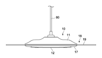
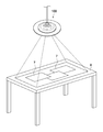
- FIG. 1 is a diagram illustrating a state in which the projector 100 according to an embodiment of the present technology is looked up from an obliquely downward direction.
- FIG. 2 is a side view showing the first unit 10 included in the projection apparatus 100.
- FIG. 3 is a diagram illustrating a state where the first unit 10 included in the projection apparatus 100 is looked up obliquely from below.
- FIG. 4 is a side sectional view of the first unit 10 included in the projection apparatus 100.
- FIG. 5 is a side sectional view of the second unit 50 included in the projection apparatus 100.
- the projection apparatus 100 (illumination apparatus 100) shown in these drawings is a type of projection apparatus 100 that is used by being suspended from a ceiling (a body to be installed).
- a general-purpose attachment 6 for a lighting device (see FIG. 5) that can be commonly used for different types of lighting devices is usually provided on the top surface 5 of the room.
- the fixture 6 is standardized according to JIS standards (Japanese Industrial Standards), and is provided on the top surface 5 for the purpose of supplying power to the lighting device and hanging the lighting device. Yes.
- the projection apparatus 100 according to the present embodiment is assumed to be used by being attached to such a general-purpose attachment 6. In the case of overseas, not the general-purpose mounting tool 6 but a dedicated mounting tool 6 may be used.
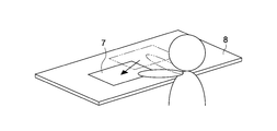
- FIG. 6 is a diagram showing a state when the image 7 is projected by the projection device 100.
- the projection apparatus 100 according to the present embodiment can project various images 7 on the upper surface of the table 8 using the upper surface of the table 8 as a screen.
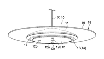
- lighting device 100 includes lower first unit 10, upper second unit 50, and a connecting portion that connects first unit 10 and second unit 50. 80.
- the first unit 10 includes a first housing 11 and a lower plate 12 provided on the lower side of the first housing 11.
- the first housing 11 has a disk shape that is thin in the thickness direction and has a hollow inside.
- the lower plate 12 is thin in the thickness direction and has a solid disk shape.
- the lower plate 12 is attached to the first casing 11 so that the internal structure disposed in the first casing 11 cannot be seen from below.
- a gap 13 is formed between the outer peripheral surface of the lower plate 12 and the first housing 11, and an intake port 14 is formed by the gap 13.
- an exhaust port 15 is formed in the upper portion of the first housing 11 (see FIG. 4).
- the ring-shaped illumination part 17 is provided in the position of the lower part in the outer peripheral side of the 1st housing
- the illuminating unit 17 is configured by a plurality of LEDs (Light Emitting) Diode) (not shown) disposed inside the first housing 11.
- the illumination unit 17 may be configured by an incandescent bulb, a fluorescent tube, or the like.
- a treble speaker 18 (second speaker) is provided at a position on the outer peripheral side of the first housing 11.
- the treble speaker 18 outputs a sound in a high frequency region higher than a predetermined threshold (in charge of outputting a sound in the high frequency region).
- the predetermined threshold value serving as a reference for high and low frequencies is appropriately set in consideration of the influence of the sound pitch on the vibration of the first unit 10.
- the threshold value is set so that a high-frequency sound that does not adversely affect the projection unit 16 and / or the illumination unit 17 is output from the treble speaker 18.
- this threshold is set to about 1.5 kHz to 500 Hz. In the present embodiment, the threshold is set to 1 khz.
- the treble speaker 18 includes a tweeter plate 19 and a vibration mechanism 20 that vibrates the tweeter plate 19.
- the tweeter plate 19 is a ring-shaped plate member that is thin in the thickness direction, and is made of a transparent material such as acrylic resin.
- the tweeter plate 19 since the tweeter plate 19 is made of a transparent material, the design can be improved.
- the diaphragm may be made of a material other than a transparent material.
- the tweeter plate 19 has a diameter larger than the diameter of the first casing 11, a part on the inner peripheral side is disposed in the casing, and the other part is outside the first casing 11. (To explain in an easy-to-understand manner, the first casing 11 and the tweeter plate 19 have a UFO-like shape as a whole).
- the vibration mechanism 20 can vibrate the entire tweeter plate 19 by vibrating a part of the tweeter plate 19 on the inner peripheral side.
- the vibration direction (vertical direction) of the vibration surface is substantially the same as the projection direction (vertical direction) by the projection unit 16.
- the image 7 compared with the case where the image 7 projected by the projection unit 16 rolls (horizontal direction), the image 7 has a visual influence on the image 7 when the image 7 shakes vertically (vertical direction). It is considered small.
- the vibration direction of the vibration surface and the projection direction of the projection unit 16 are substantially the same direction. Therefore, even if the vibration of the tweeter plate 19 is transmitted to the projection unit 16 to some extent (since it is configured to output a high-frequency region sound, the vibration is hardly transmitted to the projection unit 16).
- the projection unit 16 will be pitched (one that has less visual effect). Therefore, the influence on the image 7 generated by the vibration of the high-frequency speaker 18 can be minimized.
- vibration direction of the vibration surface of the treble speaker 18 and the projection direction of the projection unit 16 are “substantially the same” is determined from the viewpoint of shaking of the projected image 7. For example, if the difference between the vibration direction and the projection direction is about +/ ⁇ 20 °, they are substantially the same (in this embodiment, the difference is 0 °).
- a microphone 21 for acquiring voice by the user is provided inside the first casing 11.
- two depth cameras 22 (see FIG. 4) and one visible light camera 23 (RGB) are arranged at the lower position of the first housing 11 toward the lower side. Camera) (see FIG. 8).
- the two depth cameras 22 are, for example, cameras for detecting the position of the table 8 in the depth direction, the position of the user's hand with respect to the table 8, the position of the object 9 (see FIG. 10) placed on the table 8. It is.
- One visible light camera 23 is a camera for identifying the object 9 placed on the table 8.
- the depth camera 22 is an infrared camera.
- the depth camera 22 may be configured by a visible light camera.
- openings 12b are formed at positions corresponding to the three cameras so as to penetrate the lower plate 12 in the vertical direction (see FIG. 3).
- two depth cameras 22 are provided to detect a hand operation (that is, a touch operation) on the image 7 displayed on the table 8.
- a touch sensor may be provided on the table 8. In this case, information from the touch sensor is transmitted to the projection apparatus 100 wirelessly or by wire.
- the projection apparatus 100 has two modes of a projection apparatus mode and an illumination apparatus 100 mode.
- the projection device mode is a mode in which the light from the illumination unit 17 is turned off and the projection unit 16 performs projection.
- the illumination device 100 mode is a mode in which the illumination unit 17 lights up and the projection unit 16 does not perform projection. That is, in the present embodiment, the projection device 100 can be used as either the projection device 100 or the illumination device 100.
- the projection device 100 When the projection device 100 according to the present embodiment detects a specific gesture operation of a hand by a user or a specific voice input to a microphone, the projection device 100 operates in either the projection device mode or the illumination device 100 mode in accordance with the input. It is configured to switch between. Note that switching between the projection apparatus mode and the illumination apparatus 100 mode may be performed by a remote controller.
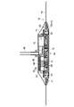
- a cooling mechanism 40 for cooling the laser oscillator 28 (first heat source) and for cooling the APU 24 and the FPGA 26 is provided inside the first housing 11. Details of the cooling mechanism 40 will be described later with reference to FIG.
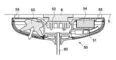
- the second unit 50 includes a second housing 51 having a hemispherical shape with the upper half cut off.
- a socket portion 52 for attaching the second unit 50 to the fixture 6 provided on the top surface 5 is provided at a position on the upper side in the center of the second housing 51.
- the socket part 52 includes two claw-shaped metal terminals (not shown) on the upper part of the socket part 52, and the projection apparatus 100 is attached to the attachment tool 6 by hooking the metal terminals against the attachment tool 6. Are electrically and physically connected to each other.
- a bass speaker 53 (first speaker) is provided inside the second casing 51 at a position outside the center (left side in FIG. 5).
- the bass speaker 53 outputs a sound in a low frequency region lower than a predetermined threshold (in charge of outputting a sound in the low frequency region). That is, in the present embodiment, the speaker is divided into two according to the level of the sound frequency.
- the threshold value that serves as a reference for the high and low frequencies is set to 1 kHz.
- the low-frequency speaker 53 that generates vibration due to the output of sound in the low-frequency region is a unit different from the first unit 10 in which the projection unit 16 is provided. Arranged in a certain second unit 50. Therefore, it can suppress that the image 7 projected by the projection part 16 shakes by the output of the sound of the bass speaker 53. Thereby, it is possible to prevent the user from feeling that the image 7 is difficult to see or uncomfortable because the image 7 projected by the projection unit 16 is shaken. it can.
- the vibration direction of the vibration surface (indicated by a white arrow in FIG. 5) is substantially the same as the projection direction (vertical direction) by the projection unit 16.
- the projection unit 16 shakes at that time (the one with less visual influence). Therefore, the influence on the image 7 caused by the vibration of the bass speaker 53 can be minimized.
- vibration direction of the vibration surface of the bass speaker 53 and the projection direction of the projection unit 16 are “substantially the same” is determined from the viewpoint of shaking of the projected image 7. For example, if the difference between the vibration direction and the projection direction is about +/ ⁇ 20 °, they are substantially the same (in this embodiment, the difference is 18 °).
- the bass speaker 53 is configured to output sound with a phase earlier than that of the treble speaker 18. Thereby, at the position of the user's ear (near the middle position between the upper surface of the projection device 100 and the table 8), the sound in the low frequency region generated from the low frequency speaker 53 and the sound in the high frequency region generated from the high frequency speaker 18 are generated. Synthesized appropriately.
- an AC / DC circuit 54 (AC: Alternating) that converts an AC voltage into a DC voltage is provided at a position opposite to the side where the bass speaker 53 is provided (on the right side in FIG. 5).
- Current DC Direct Current (power supply circuit) is provided.
- a generally heavy power circuit is disposed on the second unit 50 side (that is, on the base side).
- the second unit 50 side that is, the base side
- the first unit 10 side becomes lighter, so that the weight balance is improved and the projector 100 is stably attached to the top surface 5.
- the AC / DC circuit 54 is disposed on the second unit 50 side (that is, the base side), so that the AC / DC circuit 54 is disposed on the first unit 10.
- the first unit 10 can be easily reduced in thickness. As a result, the design of the first unit 10 can be improved.
- the bass speaker 53 which is generally heavy, is disposed on the second unit 50 side (that is, the base side), the second unit 50 side (that is, the base side).
- the first unit 10 side becomes lighter. Accordingly, the weight balance is improved, and the projection apparatus 100 can be stably installed on the ceiling.
- the weight of the AC / DC circuit 54 and the weight of the bass speaker 53 are substantially the same, and the balance in the left-right direction is also maintained.
- the bass speaker 53 is arranged on the second unit 50 side (that is, the base side), a speaker that outputs sounds of all frequencies is arranged in the first unit 10. Compared to the above, the thickness of the first unit 10 can be easily reduced. As a result, the design of the first unit 10 can be improved.
- a plurality of vibration control portions 55 are provided on the upper surface of the second casing 51 so as to protrude from the upper surface toward the ceiling (installed body side).
- the vibration control part 55 can be stably fixed to the top surface 5 while suppressing vibrations of the second unit 50 by contacting the ceiling at the upper part thereof. It is possible.
- the damping unit 55 is configured by an elastic body such as rubber having a predetermined elastic force.
- the shape of the damping unit 55 is a cylindrical shape, but the shape of the damping unit 55 can be changed as appropriate (for example, spherical, hemispherical, etc.).
- the vibration control unit 55 is disposed at a predetermined distance from the center of the second casing 51 (a position where the connecting unit 80 is provided) at a predetermined distance along the circumferential direction. .
- the stability of the second unit 50 with respect to the top surface 5 is higher when the distance from the center of the second housing 51 to the vibration control unit 55 is as far as possible. From such a viewpoint, in the example illustrated in FIG. 5, the vibration damping portion 55 is disposed at an outer position on the upper surface of the second housing 51.
- the number of vibration control units 55 is three in this embodiment.
- the stability of the second unit 50 with respect to the top surface 5 is further enhanced by the second casing 51 coming into contact with the top surface 5 at three points.
- the number of control units 1 is not limited to three, and may be four or five (at least three or more).
- the connecting portion 80 is provided so as to connect the center of the first unit 10 and the center of the second unit 50.
- the connecting portion 80 is a hollow cylindrical member (shaft) inside, and power and communication wirings are passed through the inside.
- the connection part 80 is comprised by the member which has more than fixed rigidity like a metal or resin, for example. That is, the connecting portion 80 can connect the first unit 10 and the second unit 50 to a rigid. Thereby, the first unit 10 is prevented from swaying due to, for example, the influence of wind, and the image 7 projected from the projection unit 16 can be prevented from swaying.
- connection part 80 may be comprised with elastic bodies, such as rubber
- the shaft has been described as an example of the connecting portion, but examples of the connecting portion include a cable, a wire, and a chain.
- FIG. 7 is a schematic diagram showing the cooling mechanism 40.
- the cooling mechanism 40 includes a first heat sink 41 for cooling the laser oscillator 28 (first heat source), an APU 24 and an FPGA 26 (second heat source: temperature higher than that of the first heat source).
- a second heat sink 42 for cooling the second heat sink 42 and an axial fan 43 interposed between the first heat sink 41 and the second heat sink 42.
- the cooling mechanism 40 includes a plurality of heat pipes 44 for transferring heat generated in the APU 24 and the FPGA 26 to the heat sink.
- the APU 24 and the FPGA 26 may rise to 100 ° or more, and the laser oscillator 28 may rise to about 45 °, for example. That is, the APU 24 and the FPGA 26 are heat sources having a temperature higher than that of the laser oscillator 28.
- the first heat sink 41 and the second heat sink 42 are configured by a plurality of radiating fins 41a and 42a which are arranged upright in the vertical direction and arranged at a predetermined interval.
- the laser oscillator 28 is disposed so as to enter the inside of the first heat sink 41.
- the heat pipe 44 is filled with a hydraulic fluid such as water in a reduced pressure state, and a wick for generating a capillary force is formed on the inner wall portion thereof.
- a hydraulic fluid such as water in a reduced pressure state
- a wick for generating a capillary force is formed on the inner wall portion thereof.
- One end portion 44a (evaporating portion 44a) of the heat pipe 44 is heated with the APU 24 and the FPGA 26 via the first heat diffusion plate 45 that diffuses the heat of the APU 24 and the second heat diffusion plate 46 that diffuses the heat of the FPGA 26. Are in contact.
- One end portion 44a (evaporating portion 44a) of the heat pipe 44 is disposed at a position sandwiched between the APU 24 and the FPGA 26 in the vertical direction.
- the APU substrate 25, the first heat diffusion plate 45, the FPGA 26, and the second heat diffusion plate 46 are integrally fixed by a method such as screwing.
- the other end 44 b (condensing part 44 b) of the heat pipe 44 is in contact with the second heat sink 42. Specifically, a hole having a size corresponding to the diameter of the heat pipe 44 is formed in the second heat sink 42 in the horizontal direction (the direction orthogonal to the direction in which the airflow is generated). The other end 44b of the second heat sink 42 is fitted.
- the heat pipe 44 is arranged such that the condensing part 44b of the heat pipe 44 is higher than the evaporation part 44a of the heat pipe 44.
- the hydraulic fluid evaporated in the evaporation part 44a can reach
- the hydraulic fluid condensed in the condenser 44b can smoothly reach the evaporator 44a (because the hydraulic fluid moves by gravity in addition to the capillary force). Therefore, the heat transfer efficiency by the heat pipe 44 can be improved.
- the number of heat pipes 44 is three in this embodiment, but this number can be changed as appropriate.
- the axial fan 43 generates an air flow toward the upper side in the axial direction (vertical direction), forcing the warm air in the first heat sink 41 and the second heat sink 42 to the outside of the first unit 10. Let it drain.
- the air inlet 14 is formed by the gap 13 between the first casing 11 and the lower plate 12 in the first unit 10 as described above.
- the exhaust port 15 is provided on the upper surface of the first housing 11.
- these heat sinks are arranged in the order of the first heat sink 41 and the second heat sink 42 from the upstream side of the airflow. This prevents the laser oscillator 28 from being exposed to a high temperature.
- the effect that the heat of the second heat sink 42 (high temperature) is not easily transmitted to the first heat sink 41 by interposing the axial fan 43 between the first heat sink 41 and the second heat sink 42. There is also. From this point of view as well, in this embodiment, the temperature of the laser oscillator 28 is prevented from rising.
- the first heat sink 41 corresponding to the low heat source (laser oscillator 28) is disposed at the upper position of the second heat sink 42 corresponding to the high heat source (APU 24 and FPGA 26).
- the axial fan 43 a natural airflow is further generated from the lower side to the upper side along the vertical direction.
- the heat dissipation effect of the cooling mechanism 40 is further improved.
- the axial fan 43 is disposed so as to be sandwiched between the first heat sink 41 and the second heat sink 42. Therefore, the noise generated from the axial fan 43 is absorbed by the first heat sink 41 and the second heat sink 42, and there is an advantage that the noise is reduced.
- FIG. 8 is a block diagram showing an electrical configuration of the projection apparatus 100.
- the projection apparatus 100 includes the projection unit 16, the illumination unit 17, the high tone speaker 18, the depth camera 22, the visible light camera 23, the axial fan 43, the low tone speaker 53, and the AC / DC circuit 54.
- a control unit 1, a storage unit 2, and a communication unit 3 are provided.
- the control unit 1, the storage unit 2, and the communication unit 3 are mounted on various substrates arranged inside the first unit 10.
- the control unit 1 includes the APU 24 and the FPGA 26 described above.
- the APU 24 comprehensively controls each unit of the projection apparatus 100.
- the FPGA 26 mainly executes image processing for projecting the image 7 in the projection unit 16.
- the control unit 1 executes various processes for reducing the shaking of the image 7 of the projection unit 16 and the flickering of the lighting unit 17 caused by the vibration of the bass speaker 53. This process will be described in detail later in the explanation of operation.
- the storage unit 2 includes a nonvolatile memory (for example, ROM (Read Only Memory)) in which various programs and various data are fixedly stored, and a volatile memory (as a work area of the control unit 1).
- ROM Read Only Memory
- RAM Random Access Memory
- the program may be read from a portable recording medium such as an optical disk or a semiconductor device, or may be downloaded from a server device on a network.
- the communication unit 35 is configured to be connectable to a network, and is configured to be able to communicate with other devices (for example, server devices) via the network.
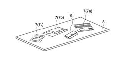
- FIG. 10 shows an example when the household account book application image 7a, the recipe search site 7b, and the food mail order site 7c are displayed when the wallet 9 is placed on the table 8.
- the control unit 1 When the depth camera 22 (detection unit) detects a specific gesture operation on the table 8 (for example, an operation of lowering the hand from the top to the bottom by a predetermined distance or more), the control unit 1 is output from the bass speaker 53. The process of lowering the volume of sound in the low frequency region is executed. As a result, the user can arbitrarily lower the volume of the bass speaker 53 by performing a gesture operation when the image 7 of the projection unit 16 shakes and the flickering of the illumination unit 17 is a concern. . That is, the user can arbitrarily suppress the shaking of the image 7 of the projection unit 16 and the flickering of the lighting unit 17.
- the control unit 1 determines whether the depth camera 22 (detection unit) detects another specific hand gesture operation on the table 8 (for example, an operation of raising the hand from below to above a predetermined distance).
- the control unit 1 detects another specific hand gesture operation on the table 8 (for example, an operation of raising the hand from below to above a predetermined distance)
- the control unit 1 determines whether the depth camera 22 (detection unit) detects another specific hand gesture operation on the table 8 (for example, an operation of raising the hand from below to above a predetermined distance)
- the control unit 1 detects another specific hand gesture operation on the table 8 (for example, an operation of raising the hand from below to above a predetermined distance)
- the control unit 1 detects another specific hand gesture operation on the table 8 (for example, an operation of raising the hand from below to above a predetermined distance) is detected.
- the control unit 1 When a specific gesture operation (for example, an operation of drawing x in space) is detected on the table 8 by the depth camera 22 (detection unit), the control unit 1 outputs a sound in a low-frequency region from the low-frequency speaker 53.
- the bass speaker 53 is controlled so as not to occur.
- the user can arbitrarily turn off the sound of the bass speaker 53 by performing a gesture operation when the image 7 of the projection unit 16 shakes and the flickering of the lighting unit 17 is a concern. . That is, the user can arbitrarily suppress the shaking of the image 7 of the projection unit 16 and the flickering of the lighting unit 17.
- the depth camera 22 detects another specific hand gesture operation on the table 8 (for example, a drawing operation in a space)
- a sound is output from the bass speaker 53.
- the bass speaker 53 is controlled. Accordingly, the user can arbitrarily output a sound from the bass speaker 53 by performing a gesture operation when the image 7 of the projection unit 16 is not shaken and the flickering of the illumination unit 17 is not concerned. it can.
- control unit 1 changes the volume of the bass speaker 53 but does not change the volume of the treble speaker 18.
- control unit 1 may change the volume of the treble speaker 18 in accordance with the change in the volume of the bass speaker 53 (the change in the volume of the treble speaker 18 may be less than the change in the volume of the bass speaker 53. it can).
- the projection apparatus 100 is provided with a vibration detection unit (for example, an acceleration sensor, an angular velocity sensor, etc.) that detects the vibration of the bass speaker 53.
- the vibration detection unit may be provided directly on the bass speaker 53 or may be provided indirectly at a place other than the bass speaker 53 (for example, the bass speaker in the second unit 50). 53, the connecting part 80, the first unit 10).
- the control unit 1 may estimate (detect) the vibration of the bass speaker 53 based on the volume of the bass speaker 53. In this case, since the control part 1 has a role as a vibration detection part, it is not necessary to provide a vibration detection part specially.
- the control unit 1 warns the user in accordance with the vibration detected (estimated) by the vibration detection unit.
- the warning is performed by the image 7 by the projection unit 16 (warning unit), sound from the speakers 18 and 53 (warning unit), and the like.
- the control unit 1 determines whether or not the vibration detected (estimated) by the vibration detection unit exceeds a predetermined vibration threshold.
- a warning is given to the user by the image 7 by the projection unit 16, sound from the speakers 18 and 53, and the like. Accordingly, when there is a possibility that the image 7 of the projection unit 16 is shaken or the light of the illumination unit 17 is flickering, a warning can be appropriately given to the user.
- the control unit 1 adjusts the amount of sound in the low frequency region output from the bass speaker 53 in accordance with the vibration detected (estimated) by the vibration detection unit. Specifically, the control unit 1 determines whether or not the vibration detected (estimated) by the vibration detection unit exceeds a predetermined vibration threshold. When the vibration exceeds the vibration threshold, the control unit 1 adjusts the volume so as to reduce the amount of sound in the low-frequency region output from the bass speaker 53 (including canceling the sound). .
- control unit 1 can automatically adjust the amount of sound in the low frequency region to automatically suppress the shaking of the image 7 of the projection unit 16 and the flickering of the lighting unit 17.
- control unit 1 may adjust the volume so as to increase the amount of sound in the low frequency region output from the bass speaker 53.
- control unit 1 controls the imaging unit so that the projection unit 16 projects the image 7 in a plurality of display modes including at least a still image display mode and a moving image display mode. And the control part 1 described above 3. according to the display mode. And 4.
- the vibration threshold value is controlled variably. Specifically, the control unit 1 controls the vibration threshold so that the vibration threshold in the still image mode is lower than the vibration threshold in the moving image display mode.
- the vibration threshold value in the still image display mode is set lower than the vibration threshold value in the moving image display mode.
- the volume is automatically adjusted even with a smaller vibration than in the moving image display mode (in the case of the above example 4).
- the vibration threshold value can be appropriately changed according to the display mode in this way.
- the projection device 100 includes both the projection unit 16 and the illumination unit 17 has been described.
- any one of these can be omitted (when the projection unit 16 is omitted, the device is the lighting device 100). That is, even if one of the projection unit 16 and the illumination unit 17 is omitted, the effect of reducing one of the shaking of the image 7 by the projection unit 16 and the flickering of the light by the illumination unit 17 can be achieved.
- the high-frequency speaker 18 is provided for the first unit 10 and the low-frequency speaker 53 is provided for the second unit 50.
- a speaker hereinafter referred to as an all-range speaker: first speaker
- the second unit 50 may be provided for the second unit 50 (in this case, the first unit 10 includes Does not have a speaker).
- the low frequency region sound (the main cause of the shaking of the image 7 and the flickering of the light) is output to a unit different from the unit provided with the projection unit 16 and the illumination unit 17.
- a range speaker will be provided. That is, also in the case of this example, the shaking of the image 7 by the projection unit 16 and the flickering of the light by the illumination unit 17 can be appropriately suppressed.
- a specific gesture operation for example, an operation of lowering the hand by a predetermined distance or more from the top to the bottom
- the control unit 1 executes a process of reducing the amount of sound corresponding to the low frequency region among all the frequency region sounds output from the all-range speaker.
- the all-range speaker is used. A process of increasing the amount of sound corresponding to the low frequency region out of all output frequency region sounds is executed.
- control boards such as the APU board 25 and the FPGA board 27 are provided for the first unit 10 has been described.
- these control substrates may be provided for the second unit 50.
- the heat pipe 44 and the second heat sink 42 are also provided for the second unit 50.
- the projection apparatus 100 may be installed on a floor, a side wall, a table, or the like.
- the position where the projection apparatus 100 is installed is not limited to indoors but may be outdoor.
- This technique can also take the following composition.
- a first unit having a projection unit for projecting an image;
- a second unit having a first speaker that outputs at least a sound in a low frequency region lower than a predetermined threshold;
- a connecting portion for connecting the first unit and the second unit;
- the second unit is positioned closer to the installation object than the first unit when the projection apparatus is installed on another installation object.
- Projection device (2)
- the projection apparatus according to (1) above, The first speaker is in charge of outputting a sound in a low frequency region lower than the predetermined threshold
- the first unit includes a second speaker in charge of outputting a sound in a high frequency region higher than the predetermined threshold.
- the first unit includes a lighting unit.
- the second unit further includes a power supply circuit.
- the projection apparatus according to any one of (1) to (4) above, The first speaker has a vibration surface that generates sound by vibration; The vibration direction of the vibration surface is substantially the same as the projection direction of the image by the projection unit.
- the projection apparatus according to (2) above, The second speaker has a vibration surface that generates sound by vibration, The vibration direction of the vibration surface is substantially the same as the projection direction of the image by the projection unit.
- a detection unit for detecting a user operation A projection apparatus further comprising: a control unit that adjusts an amount of sound in the low-frequency region output from the first speaker in accordance with the detected user operation.
- the control unit controls the first speaker so that the sound in the low frequency region is not output from the first speaker in response to the user operation.
- a warning section that warns the user;
- a control unit that controls the warning unit so as to warn a user in response to the detected vibration of the first speaker.
- the control unit determines whether or not the vibration of the first speaker exceeds a predetermined vibration threshold value, and controls the warning unit to warn the user when the vibration exceeds the vibration threshold value.
- Projection device (11) The projection apparatus according to any one of (1) to (10) above, A vibration detector for detecting vibrations of the first speaker; And a control unit that adjusts an amount of sound in the low-frequency region output from the first speaker in accordance with the detected vibration of the first speaker. (12) The projection device according to (11) above, The control unit determines whether or not the vibration of the first speaker exceeds a predetermined vibration threshold value. When the vibration exceeds the vibration threshold value, the low frequency region output from the first speaker is determined.
- a projection device that adjusts the volume to reduce the volume of sound.
- the control unit variably controls the vibration threshold.
- the control unit controls the projection unit to cause the projection unit to project an image in a plurality of display modes, and variably controls the vibration threshold according to the display mode.
- the second unit further includes a vibration damping unit that is provided on a surface on the object to be installed side so as to protrude from the surface toward the object to be installed, and that comes into contact with the object to be installed.
- the connecting portion is one of a shaft, a cable, a wire, and a chain.
Landscapes
- Physics & Mathematics (AREA)
- Engineering & Computer Science (AREA)
- Acoustics & Sound (AREA)
- Signal Processing (AREA)
- Health & Medical Sciences (AREA)
- Otolaryngology (AREA)
- General Physics & Mathematics (AREA)
- Projection Apparatus (AREA)
- Arrangement Of Elements, Cooling, Sealing, Or The Like Of Lighting Devices (AREA)
- Non-Portable Lighting Devices Or Systems Thereof (AREA)
- Transforming Electric Information Into Light Information (AREA)
Abstract
A projection device according to the present invention is provided with a first unit, a second unit, and a connecting section. The first unit comprises a projection unit. The second unit comprises a first speaker for outputting at least sound in a low frequency range that is lower than a predetermined threshold value. The second unit is positioned on the installation surface side on which the projection device is installed. The connecting section connects the first unit and the second unit.
Description
本技術は、投影装置及び照明装置に関する。
This technology relates to a projection device and an illumination device.
状来から、スクリーン上に画像(映像)を投影する投影装置が広く知られている。一般的に、投影装置は、テーブル上に設置されて使用されるが、天吊り器具などによって天井にぶら下げて使用される場合もある(例えば、特許文献1参照)。また、投影装置は、一般的に、箱状の1つの筐体内部に、光源、レンズ等の各種光学系によって構成された投影部、スピーカなどが内蔵されて構成されている。
Projectors that project an image (video) on a screen have been widely known since the past. In general, the projection apparatus is used by being installed on a table. However, the projection apparatus may be used by being hung on a ceiling by a ceiling hanger (for example, see Patent Document 1). In general, a projection apparatus is configured such that a projection unit constituted by various optical systems such as a light source and a lens, a speaker, and the like are incorporated in a box-shaped casing.
ここで、スピーカが音を発生するときに振動が生じ、この振動に起因して投影部が振動してしまう場合がある。この場合、投影部によりスクリーン上に投影される画像が揺れてしまう場合がある。
Here, vibration may occur when the speaker generates sound, and the projection unit may vibrate due to this vibration. In this case, the image projected on the screen by the projection unit may shake.
以上のような事情に鑑み、本技術の目的は、スピーカによる振動によって、投影部により投影される画像が揺れてしまうことを抑制することができる投影装置等の技術を提供することにある。
In view of the circumstances as described above, an object of the present technology is to provide a technology such as a projection device that can suppress the image projected by the projection unit from being shaken by the vibration of the speaker.
本技術に係る投影装置は、第1のユニットと、第2のユニットと、連結部とを具備する。
前記第1のユニットは、映像を投影する投影部を有する。
前記第2のユニットは、所定の閾値よりも低い低周波領域の音を少なくとも出力する第1のスピーカを有する。
前記連結部は、前記第1のユニット及び第2のユニットを連結する。
また、前記第2のユニットは、投影装置が他の被設置体に設置されるときに前記第1のユニットよりも前記被設置体側に位置する。 The projection apparatus according to the present technology includes a first unit, a second unit, and a connecting unit.
The first unit includes a projection unit that projects an image.
The second unit includes a first speaker that outputs at least sound in a low frequency region lower than a predetermined threshold.
The connecting portion connects the first unit and the second unit.
The second unit is positioned closer to the installation object than the first unit when the projection apparatus is installed on another installation object.
この投影装置は、分離された2つのユニットにより構成されている。そして、音の出力(特に、低周波領域の音の出力)により振動を発生させてしまう第1のスピーカが、投影部が設けられたユニット(第1のユニット)とは別のユニット(第2のユニット)に配置されている。従って、投影部によって投影される画像が、第1のスピーカの音の出力によって揺れてしてしまうことを抑制することができる。
This projection device is composed of two separated units. The first speaker that generates vibration due to the sound output (particularly, the sound output in the low frequency region) is a unit (second unit) different from the unit (first unit) provided with the projection unit. In the unit). Therefore, it can suppress that the image projected by a projection part shakes by the output of the sound of a 1st speaker.
ここで、低周波領域の基準となる「所定の閾値」は、音の高さが振動に与える影響を考慮して適宜設定される(例えば、1.5kHz~500Hz)。また、「被設置体」は、天井、側壁、床、テーブル等である(なお、屋内、屋外を問わない)。
Here, the “predetermined threshold value” serving as a reference for the low frequency region is appropriately set in consideration of the influence of the sound pitch on the vibration (for example, 1.5 kHz to 500 Hz). Further, the “installed body” is a ceiling, a side wall, a floor, a table, or the like (regardless of indoors or outdoors).
上記投影装置において、前記第1のスピーカは、前記所定の閾値よりも低い低周波領域の音の出力を担当してもよい。この場合、前記第1のユニットは、前記所定の閾値よりも高い高周波領域の音の出力を担当する第2のスピーカを有していてもよい。
In the projection apparatus, the first speaker may be in charge of outputting a sound in a low frequency region lower than the predetermined threshold. In this case, the first unit may include a second speaker in charge of outputting a sound in a high frequency region higher than the predetermined threshold.
この投影装置では、投影部と同じユニット(第1のユニット)に対して第2のスピーカが配置されている。しかし、高周波領域の音は、振動に与える影響が小さいので、第2のスピーカから音が発生しても、投影部はほとんど振動しない。一方、振動の主たる原因である低周波領域の音を発生させる第1のスピーカは、投影部とは分離するように配置されている。従って、投影部によって投影される画像が、第1のスピーカの音の出力によって揺れてしてしまうことを抑制することができる。
In this projection apparatus, the second speaker is arranged with respect to the same unit (first unit) as the projection unit. However, since the sound in the high frequency region has little influence on the vibration, even if the sound is generated from the second speaker, the projection unit hardly vibrates. On the other hand, the first speaker that generates the sound in the low frequency region, which is the main cause of vibration, is arranged so as to be separated from the projection unit. Therefore, it can suppress that the image projected by a projection part shakes by the output of the sound of a 1st speaker.
上記投影装置において、前記第1のユニットは、照明部を有していてもよい。
In the projection apparatus, the first unit may include an illumination unit.
この投影装置では、投影部の他に、照明部が第1のユニットに設けられている。一方、振動の原因となる第1のスピーカは、第2のユニットに設けられているため、照明が第1のスピーカの振動により振動してしまい、照明部による明かりがちらついてしまうことを防止することができる。
In this projection apparatus, in addition to the projection unit, an illumination unit is provided in the first unit. On the other hand, since the first speaker that causes vibration is provided in the second unit, the illumination is vibrated by the vibration of the first speaker, and the light from the illumination unit is prevented from flickering. be able to.
上記投影装置において、前記第2のユニットは、電源回路をさらに有していてもよい。
In the projection apparatus, the second unit may further include a power supply circuit.
この投影装置では、一般的に重量が重い電源回路が第2のユニット側(つまり、基部側)に配置される。これにより、第2のユニット側(つまり、基部側)が重くなり、一方で、第1のユニット側が軽くなるため、重量バランスが良くなり、投影装置を安定して被設置体に対して設置しておくことができる。
In this projection apparatus, generally a heavy power circuit is arranged on the second unit side (that is, the base side). As a result, the second unit side (that is, the base side) becomes heavier, while the first unit side becomes lighter, so that the weight balance is improved and the projection apparatus is stably installed on the installation target. I can keep it.
上記投影装置において、前記第1のスピーカは、振動によって音を発生させる振動面を有し、前記振動面の振動方向は、前記投影部による画像の投影方向と実質的に同一であってもよい。
In the projection apparatus, the first speaker may have a vibration surface that generates sound by vibration, and a vibration direction of the vibration surface may be substantially the same as a projection direction of an image by the projection unit. .
ここで、画像が横揺れ(投影方向に垂直な方向への揺れ)してしまう場合に比べて、画像が縦揺れ(投影方向に平行な方向への揺れ)したときの方が、画像に対する見た目上の影響が小さいと考えられる。一方、この投影装置では、振動面の振動方向と、投影部の投影方向とが実質的に同一とされているので、第1のスピーカの振動が投影部に多少伝わってしまったとしても、そのとき投影部は縦揺れ(見た目上の影響が少ない方)することになる。従って、第1のスピーカの振動により発生する画像への影響を最小限にとどめることができる。
Here, compared to the case where the image sways (sway in a direction perpendicular to the projection direction), the image appears to be more visually swayed (sway in the direction parallel to the projection direction). The above effect is considered to be small. On the other hand, in this projection apparatus, since the vibration direction of the vibration surface and the projection direction of the projection unit are substantially the same, even if the vibration of the first speaker is transmitted to the projection unit to some extent, Sometimes the projection part will oscillate (the one with less visual effect). Therefore, the influence on the image generated by the vibration of the first speaker can be minimized.
振動面の振動方向と、画像の投影方向が「実質的に同一」かどうかは、投影される画像の揺れの観点から決定され、例えば、振動方向と投影方向との差が+/-20°程度であれば、実質的に同一とされる。
Whether the vibration direction of the vibration surface and the projection direction of the image are “substantially the same” is determined from the viewpoint of shaking of the projected image. For example, the difference between the vibration direction and the projection direction is +/− 20 °. If it is, it is substantially the same.
上記投影装置において、前記第2のスピーカは、振動によって音を発生させる振動面を有し前記振動面の振動方向は、前記投影部による画像の投影方向と実質的に同一であってもよい。
In the projection apparatus, the second speaker may have a vibration surface that generates sound by vibration, and a vibration direction of the vibration surface may be substantially the same as a projection direction of an image by the projection unit.
この投影装置では、振動面の振動方向と、投影部の投影方向とが実質的に同一とされているので、第1のスピーカの振動が投影部に多少伝わってしまったとしても、そのとき投影部は縦揺れ(見た目上の影響が少ない方)することになる。従って、第1のスピーカの振動により発生する画像への影響を最小限にとどめることができる。
In this projection apparatus, since the vibration direction of the vibration surface and the projection direction of the projection unit are substantially the same, even if the vibration of the first speaker is transmitted to the projection unit to some extent, the projection is performed at that time. The part will sway (the one with less visual effect). Therefore, the influence on the image generated by the vibration of the first speaker can be minimized.
振動面の振動方向と、画像の投影方向が「実質的に同一」かどうかは、投影される画像の揺れの観点から決定され、例えば、振動方向と投影方向との差が+/-20°程度であれば、実質的に同一とされる。
Whether the vibration direction of the vibration surface and the projection direction of the image are “substantially the same” is determined from the viewpoint of shaking of the projected image. For example, the difference between the vibration direction and the projection direction is +/− 20 °. If it is, it is substantially the same.
上記投影装置は、ユーザ操作を検出する検出部と、検出された前記ユーザ操作に応じて、前記第1のスピーカから出力される前記低周波領域の音の量を調整する制御部とをさらに具備していてもよい。
The projection apparatus further includes a detection unit that detects a user operation, and a control unit that adjusts the amount of sound in the low-frequency region output from the first speaker in accordance with the detected user operation. You may do it.
これにより、ユーザは、ユーザ操作により低周波数領域の音の量を調整することによって、任意に画像の揺れを抑制することができる。
Thereby, the user can arbitrarily suppress the shaking of the image by adjusting the amount of sound in the low frequency region by the user operation.
上記投影装置において、前記制御部は、前記ユーザ操作に応じて、前記第1のスピーカから前記低周波領域の音が出力されないように、前記第1のスピーカを制御してもよい。
In the projection apparatus, the control unit may control the first speaker so that sound in the low frequency region is not output from the first speaker in response to the user operation.
これにより、ユーザは、ユーザ操作により低周波数領域の音の量を調整することによって、任意に画像の揺れを抑制することができる。
Thereby, the user can arbitrarily suppress the shaking of the image by adjusting the amount of sound in the low frequency region by the user operation.
上記投影装置は、ユーザに警告を行う警告部と、前記第1のスピーカの振動を検出する振動検出部と、検出された前記第1のスピーカの振動に応じて、ユーザに警告を行うように前記警告部を制御する制御部とをさらに具備していてもよい。
The projection apparatus warns the user according to the warning unit that warns the user, the vibration detection unit that detects the vibration of the first speaker, and the detected vibration of the first speaker. And a control unit that controls the warning unit.
これにより、画像が揺れてしてしまう可能性がある場合に、ユーザに対して警告を行うことができる。
This makes it possible to warn the user when there is a possibility that the image will shake.
上記投影装置において、前記制御部は、前記第1のスピーカの振動が所定の振動閾値を超えたかどうかを判定し、前記振動が前記振動閾値を超えた場合、ユーザに前記警告を行うように前記警告部を制御してもよい。
In the projection apparatus, the control unit determines whether or not the vibration of the first speaker exceeds a predetermined vibration threshold value. When the vibration exceeds the vibration threshold value, the control unit performs the warning to the user. The warning unit may be controlled.
これにより、画像が揺れてしてしまう可能性がある場合に、ユーザに対して警告を行うことができる。
This makes it possible to warn the user when there is a possibility that the image will shake.
上記投影装置において、前記第1のスピーカの振動を検出する振動検出部と、検出された前記第1のスピーカの振動に応じて、前記第1のスピーカから出力される前記低周波領域の音の音量を調整する制御部とをさらに具備する具備していてもよい。
In the projection device, a vibration detection unit that detects vibration of the first speaker, and a sound of the low frequency region that is output from the first speaker according to the detected vibration of the first speaker. And a control unit that adjusts the volume.
これにより、第1のスピーカの振動量に応じて、制御部により自動的に低周波領域の音の量を調整して自動的に画像の揺れを抑制することができる。
Thereby, according to the amount of vibration of the first speaker, the amount of sound in the low frequency region can be automatically adjusted by the control unit to automatically suppress the shaking of the image.
上記投影装置において、前記制御部は、前記第1のスピーカの振動が所定の振動閾値を超えたかどうかを判定し、前記振動が前記振動閾値を超えた場合、前記第1のスピーカから出力される前記低周波領域の音の量を小さくするように調整してもよい。
In the projection apparatus, the control unit determines whether or not the vibration of the first speaker exceeds a predetermined vibration threshold value. If the vibration exceeds the vibration threshold value, the control unit outputs the vibration from the first speaker. You may adjust so that the quantity of the sound of the said low frequency area may be made small.
これにより、第1のスピーカの振動量に応じて、制御部により自動的に低周波領域の音の量を調整して自動的に画像の揺れを抑制することができる。
Thereby, according to the amount of vibration of the first speaker, the amount of sound in the low frequency region can be automatically adjusted by the control unit to automatically suppress the shaking of the image.
上記投影装置において、前記制御部は、前記振動閾値を可変に制御してもよい。
In the projection apparatus, the control unit may variably control the vibration threshold.
これにより、振動閾値を適切に変更することができる。
This makes it possible to change the vibration threshold appropriately.
上記投影装置において、前記制御部は、複数の表示モードで前記投影部に画像を投影させるように前記投影部を制御し、かつ、前記表示モードに応じて、前記振動閾値を可変に制御してもよい。
In the projection apparatus, the control unit controls the projection unit to project an image on the projection unit in a plurality of display modes, and variably controls the vibration threshold according to the display mode. Also good.
これにより、表示モードに応じて、振動閾値を適切に変更することができる。
This makes it possible to change the vibration threshold appropriately according to the display mode.
上記投影装置において、前記複数の表示モードは、静止画表示モード及び動画表示モードを含み、前記制御部は、前記静止画モードにおける前記振動閾値が、動画表示モードにおける前記振動閾値よりも低くなるように、前記振動閾値を制御してもよい。
In the projection apparatus, the plurality of display modes include a still image display mode and a moving image display mode, and the control unit causes the vibration threshold in the still image mode to be lower than the vibration threshold in the moving image display mode. In addition, the vibration threshold value may be controlled.
ここで、静止画が揺れてしまう場合に比べて、動画が揺れたときの方が、画像に対する見た目上の影響が小さいと考えられる。一方、この投影装置では、静止画表示モードにおける振動閾値が、動画表示モードにおける振動閾値よりも低くされているため、静止画表示モードにおいて、動画表示モードよりも小さな振動でもユーザに警告が行われる(あるいは、制御部が自動的に音量を調整してもよい)。
Here, it is considered that the visual effect on the image is less when the moving image is shaken than when the still image is shaken. On the other hand, in this projection apparatus, the vibration threshold value in the still image display mode is set lower than the vibration threshold value in the moving image display mode. (Alternatively, the control unit may automatically adjust the volume).
上記投影装置において、前記第2のユニットは、前記被設置体側の面に、前記面から前記被設置体側に向けて突出するように設けられた、前記被設置体に当接する制振部をさらに有していてもよい。
In the projection apparatus, the second unit may further include a vibration control unit that is provided on the surface on the object to be installed side so as to protrude from the surface toward the object to be installed side, and is in contact with the object to be installed. You may have.
上記投影装置において、前記連結部は、シャフト、ケーブル、ワイヤ、チェーンのうちの1つであってもよい。
In the projection apparatus, the connecting portion may be one of a shaft, a cable, a wire, and a chain.
本技術に係る照明装置は、第1のユニットと、第2のユニットと、連結部とを具備する。
前記第1のユニットは、照明部を有する。
前記第2のユニットは、所定の閾値よりも低い低周波領域の音を少なくとも出力する第1のスピーカを有する。
前記連結部は、前記第1のユニット及び第2のユニットを連結する。
また、前記第2のユニットは、照明装置が他の被設置体に設置されるときに前記第1のユニットよりも前記被設置体側に位置する The lighting device according to the present technology includes a first unit, a second unit, and a connecting portion.
The first unit has an illumination unit.
The second unit includes a first speaker that outputs at least sound in a low frequency region lower than a predetermined threshold.
The connecting portion connects the first unit and the second unit.
The second unit is positioned closer to the installation object than the first unit when the lighting device is installed on another installation object.
この照明装置は、分離された2つのユニットにより構成されている。そして、音の出力(特に、低周波領域の音の出力)により振動を発生させてしまう第1のスピーカが、照明部が設けられたユニット(第1のユニット)とは別のユニット(第2のユニット)に配置されている。従って、照明部による明かりが、第1のスピーカの音の出力によってちらついてしまうことを抑制することができる。
This lighting device is composed of two separated units. The first speaker that generates vibration due to the sound output (especially the sound output in the low frequency region) is a unit (second unit) different from the unit (first unit) provided with the illumination unit. In the unit). Therefore, it can suppress that the light by an illumination part flickers by the output of the sound of a 1st speaker.
以上のように、本技術によれば、スピーカによる振動によって、投影部により投影される画像が揺れてしまうことを抑制することができる投影装置等の技術を提供することができる。
As described above, according to the present technology, it is possible to provide a technology such as a projection device that can suppress the image projected by the projection unit from being shaken by the vibration of the speaker.
以下、本技術に係る実施形態を、図面を参照しながら説明する。
Hereinafter, embodiments of the present technology will be described with reference to the drawings.
<投影装置100の全体構成及び各部の構成>
図1は、本技術の一実施形態に係る投影装置100を斜め下方向から見上げたときの様子を示す図である。図2は、投影装置100が有する第1のユニット10を示す側面図である。図3は、投影装置100が有する第1のユニット10を斜め下方向から見上げたときの様子を示す図である。図4は、投影装置100が有する第1のユニット10の側方断面図である。図5は、投影装置100が有する第2のユニット50の側方断面図である。 <Overall Configuration ofProjector 100 and Configuration of Each Unit>
FIG. 1 is a diagram illustrating a state in which theprojector 100 according to an embodiment of the present technology is looked up from an obliquely downward direction. FIG. 2 is a side view showing the first unit 10 included in the projection apparatus 100. FIG. 3 is a diagram illustrating a state where the first unit 10 included in the projection apparatus 100 is looked up obliquely from below. FIG. 4 is a side sectional view of the first unit 10 included in the projection apparatus 100. FIG. 5 is a side sectional view of the second unit 50 included in the projection apparatus 100.
図1は、本技術の一実施形態に係る投影装置100を斜め下方向から見上げたときの様子を示す図である。図2は、投影装置100が有する第1のユニット10を示す側面図である。図3は、投影装置100が有する第1のユニット10を斜め下方向から見上げたときの様子を示す図である。図4は、投影装置100が有する第1のユニット10の側方断面図である。図5は、投影装置100が有する第2のユニット50の側方断面図である。 <Overall Configuration of
FIG. 1 is a diagram illustrating a state in which the
これらの図に示す投影装置100(照明装置100)は、天井(被設置体)から吊り下げて使用するタイプの投影装置100である。日本では、通常、室内の天面5に、種類の異なる照明装置で共通で使用することできる照明装置用の汎用の取り付け具6(図5参照)が設けられている。この取り付け具6は、JIS規格(Japanese Industrial Standards)によって規格化されており、照明装置に対して電力を供給すること、並びに、照明装置を掛けておくことを目的として天面5に設けられている。本実施形態に係る投影装置100は、このような汎用の取り付け具6に対して取り付けられて使用されることが想定されている。なお、海外の場合には、このような汎用の取り付け具6ではなく、専用の取り付け具6が用いられてもよい。
The projection apparatus 100 (illumination apparatus 100) shown in these drawings is a type of projection apparatus 100 that is used by being suspended from a ceiling (a body to be installed). In Japan, a general-purpose attachment 6 for a lighting device (see FIG. 5) that can be commonly used for different types of lighting devices is usually provided on the top surface 5 of the room. The fixture 6 is standardized according to JIS standards (Japanese Industrial Standards), and is provided on the top surface 5 for the purpose of supplying power to the lighting device and hanging the lighting device. Yes. The projection apparatus 100 according to the present embodiment is assumed to be used by being attached to such a general-purpose attachment 6. In the case of overseas, not the general-purpose mounting tool 6 but a dedicated mounting tool 6 may be used.
図6は、この投影装置100によって、画像7が投影されているときの様子を示す図である。図6に示すように、本実施形態に係る投影装置100は、テーブル8の上面をスクリーンとして、テーブル8の上面に各種の画像7を投影することが可能とされている。
FIG. 6 is a diagram showing a state when the image 7 is projected by the projection device 100. As shown in FIG. 6, the projection apparatus 100 according to the present embodiment can project various images 7 on the upper surface of the table 8 using the upper surface of the table 8 as a screen.
図1~図6を参照して、照明装置100は、下側の第1のユニット10と、上側の第2のユニット50と、第1のユニット10及び第2のユニット50を連結する連結部80とを備えている。
Referring to FIGS. 1 to 6, lighting device 100 includes lower first unit 10, upper second unit 50, and a connecting portion that connects first unit 10 and second unit 50. 80.
[第1のユニット10]
第1のユニット10は、第1の筐体11と、第1の筐体11の下側の設けられた下板12とを備えている。第1の筐体11は、厚さ方向に薄い、内部が中空の円盤状の形状を有している。下板12は、厚さ方向に薄い、内部が中実の円板状の形状を有している。この下板12は、第1の筐体11内に配置された内部構造が下から見えないようにするために、第1の筐体11に対して取り付けられている。 [First unit 10]
Thefirst unit 10 includes a first housing 11 and a lower plate 12 provided on the lower side of the first housing 11. The first housing 11 has a disk shape that is thin in the thickness direction and has a hollow inside. The lower plate 12 is thin in the thickness direction and has a solid disk shape. The lower plate 12 is attached to the first casing 11 so that the internal structure disposed in the first casing 11 cannot be seen from below.
第1のユニット10は、第1の筐体11と、第1の筐体11の下側の設けられた下板12とを備えている。第1の筐体11は、厚さ方向に薄い、内部が中空の円盤状の形状を有している。下板12は、厚さ方向に薄い、内部が中実の円板状の形状を有している。この下板12は、第1の筐体11内に配置された内部構造が下から見えないようにするために、第1の筐体11に対して取り付けられている。 [First unit 10]
The
下板12の外周面と、第1の筐体11との間には、間隙13が形成されており、この間隙13によって、吸気口14が形成されている。対応して、第1の筐体11の上部には、排気口15が形成されている(図4参照)。
A gap 13 is formed between the outer peripheral surface of the lower plate 12 and the first housing 11, and an intake port 14 is formed by the gap 13. Correspondingly, an exhaust port 15 is formed in the upper portion of the first housing 11 (see FIG. 4).
第1の筐体11の内部において、中央の下部側の位置には、画像7を投影する投影部16が配置されている。この投影部16は、投影方向(本実施形態では、垂直方向)に向けて画像7を投影可能に構成されている。この投影部16は、複数のレーザ発振子28(光源)、プリズム、ミラー、集光レンズ、投影レンズ、DLP(Digital Light Processing)などの各種の光学系を含む。なお、下板12は、投影部16の投影レンズの位置に対応する位置に、開口12aが形成されている(図3参照)。
Inside the first housing 11, a projection unit 16 for projecting the image 7 is disposed at a central lower position. The projection unit 16 is configured to project the image 7 in the projection direction (vertical direction in the present embodiment). The projection unit 16 includes various optical systems such as a plurality of laser oscillators 28 (light sources), prisms, mirrors, a condenser lens, a projection lens, and DLP (Digital Light Processing). The lower plate 12 has an opening 12a at a position corresponding to the position of the projection lens of the projection unit 16 (see FIG. 3).
第1の筐体11の外周側において下部側の位置には、リング状の照明部17が設けられている。この照明部17は、本実施形態においては、第1の筐体11の内部に配置された複数のLED(Light Emitting Diode)(不図示)によって構成されている。なお、照明部17は、白熱電球、蛍光管などによって構成されていてもよい。
The ring-shaped illumination part 17 is provided in the position of the lower part in the outer peripheral side of the 1st housing | casing 11. FIG. In the present embodiment, the illuminating unit 17 is configured by a plurality of LEDs (Light Emitting) Diode) (not shown) disposed inside the first housing 11. The illumination unit 17 may be configured by an incandescent bulb, a fluorescent tube, or the like.
第1の筐体11の外周側の位置には、高音スピーカ18(第2のスピーカ)が設けられている。高音スピーカ18は、所定の閾値よりも高い高周波領域の音を出力する(高周波領域の音の出力を担当する)。周波数の高、低の基準となる所定閾値は、音の高さが第1のユニット10の振動に与える影響を考慮して適宜設定される。
A treble speaker 18 (second speaker) is provided at a position on the outer peripheral side of the first housing 11. The treble speaker 18 outputs a sound in a high frequency region higher than a predetermined threshold (in charge of outputting a sound in the high frequency region). The predetermined threshold value serving as a reference for high and low frequencies is appropriately set in consideration of the influence of the sound pitch on the vibration of the first unit 10.
すなわち、高音スピーカ18により第1のユニット10が振動してしまうと、投影部16により投影される画像7が揺れてしまうおそれがあり、また、照明部17による明かりがちらついてしまうおそれがある。特に、周波数が低い音は、第1のユニット10の振動に与える影響が大きい。従って、投影部16及び/又は照明部17に悪影響を与えない高さの音が高音スピーカ18から出力されるように、上記閾値が設定される。例えば、この閾値は、1.5kHz~500Hz程度とされる。なお、本実施形態では、閾値は、1khzに設定されている。
That is, if the first unit 10 vibrates by the high-frequency speaker 18, the image 7 projected by the projection unit 16 may be shaken, and the light from the illumination unit 17 may flicker. In particular, a sound having a low frequency has a great influence on the vibration of the first unit 10. Therefore, the threshold value is set so that a high-frequency sound that does not adversely affect the projection unit 16 and / or the illumination unit 17 is output from the treble speaker 18. For example, this threshold is set to about 1.5 kHz to 500 Hz. In the present embodiment, the threshold is set to 1 khz.
高音スピーカ18は、ツイータ板19と、ツイータ板19を振動させる振動機構20とを有している。ツイータ板19は、厚さ方向に薄い、リング状の板状の部材であり、アクリル樹脂などの透明の材料によって構成されている。本実施形態では、ツイータ板19が透明の材料によって構成されているため、デザイン性の向上を図ることできる。但し、振動板は、透明の材料以外の材料によって構成されていてもよい。
The treble speaker 18 includes a tweeter plate 19 and a vibration mechanism 20 that vibrates the tweeter plate 19. The tweeter plate 19 is a ring-shaped plate member that is thin in the thickness direction, and is made of a transparent material such as acrylic resin. In the present embodiment, since the tweeter plate 19 is made of a transparent material, the design can be improved. However, the diaphragm may be made of a material other than a transparent material.
ツイータ板19は、第1の筐体11の直径よりも大きい直径を有しており、内周側の一部が筐体内に配置され、それ以外の部分は、第1の筐体11から外側に突出している(解りやすく説明すると、第1の筐体11及びツイータ板19で全体としてUFOのような形状とされている)。振動機構20は、ツイータ板19における内周側の一部を振動させることによって、ツイータ板19の全体を振動させることが可能とされている。
The tweeter plate 19 has a diameter larger than the diameter of the first casing 11, a part on the inner peripheral side is disposed in the casing, and the other part is outside the first casing 11. (To explain in an easy-to-understand manner, the first casing 11 and the tweeter plate 19 have a UFO-like shape as a whole). The vibration mechanism 20 can vibrate the entire tweeter plate 19 by vibrating a part of the tweeter plate 19 on the inner peripheral side.
ツイータ板19は、振動面の振動方向(垂直方向)が、投影部16による投影方向(垂直方向)と実質的に同一とされている。ここで、投影部16によって投影される画像7が横揺れ(水平方向)してしまう場合に比べて、画像7が縦揺れ(垂直方向)したときの方が、画像7に対する見た目上の影響が小さいと考えられる。
In the tweeter plate 19, the vibration direction (vertical direction) of the vibration surface is substantially the same as the projection direction (vertical direction) by the projection unit 16. Here, compared with the case where the image 7 projected by the projection unit 16 rolls (horizontal direction), the image 7 has a visual influence on the image 7 when the image 7 shakes vertically (vertical direction). It is considered small.
この点を考慮して、本実施形態に係る投影装置100では、上述のように、振動面の振動方向と、投影部16の投影方向とが実質的に同一の方向とされている。これにより、ツイータ板19の振動が投影部16に多少伝わってしまったとしても(高周波領域の音が出力されるように構成されているため、ほとんど振動は投影部16に伝わらない)、そのとき投影部16は縦揺れ(見た目上の影響が少ない方)することになる。従って、高音スピーカ18の振動により発生する画像7への影響を最小限にとどめることができる。
In consideration of this point, in the projection device 100 according to the present embodiment, as described above, the vibration direction of the vibration surface and the projection direction of the projection unit 16 are substantially the same direction. Thereby, even if the vibration of the tweeter plate 19 is transmitted to the projection unit 16 to some extent (since it is configured to output a high-frequency region sound, the vibration is hardly transmitted to the projection unit 16). The projection unit 16 will be pitched (one that has less visual effect). Therefore, the influence on the image 7 generated by the vibration of the high-frequency speaker 18 can be minimized.
なお、高音スピーカ18の振動面の振動方向と、投影部16の投影方向が「実質的に同一」かどうかは、投影される画像7の揺れの観点から決定される。例えば、振動方向と投影方向との差が+/-20°程度であれば、これらが実質的に同一とされる(本実施形態では、差は、0°)。
Note that whether the vibration direction of the vibration surface of the treble speaker 18 and the projection direction of the projection unit 16 are “substantially the same” is determined from the viewpoint of shaking of the projected image 7. For example, if the difference between the vibration direction and the projection direction is about +/− 20 °, they are substantially the same (in this embodiment, the difference is 0 °).
第1の筐体11の内部には、ユーザによる音声を取得するためのマイクロフォン21(図8参照)が設けられている。また、第1の筐体11の内部において、第1の筐体11の下部側の位置には、下側に向けて2つの深度カメラ22(図4参照)及び1つの可視光カメラ23(RGBカメラ)(図8参照)が設けられている。2つの深度カメラ22は、例えば、奥行き方向における、テーブル8の位置、テーブル8に対するユーザの手の位置、テーブル8上に置かれた物体9(図10参照)の位置等を検出するためのカメラである。1つの可視光カメラ23は、テーブル8上に置かれた物体9を識別するためのカメラである。
Inside the first casing 11, a microphone 21 (see FIG. 8) for acquiring voice by the user is provided. In addition, inside the first housing 11, two depth cameras 22 (see FIG. 4) and one visible light camera 23 (RGB) are arranged at the lower position of the first housing 11 toward the lower side. Camera) (see FIG. 8). The two depth cameras 22 are, for example, cameras for detecting the position of the table 8 in the depth direction, the position of the user's hand with respect to the table 8, the position of the object 9 (see FIG. 10) placed on the table 8. It is. One visible light camera 23 is a camera for identifying the object 9 placed on the table 8.
本実施形態では、深度カメラ22は、赤外線カメラによって構成されている。一方、この深度カメラ22は、可視光カメラによって構成されていてもよい。なお、下板12において、3つのカメラに対応する位置には、それぞれ、下板12を上下方向に貫通するように、開口12bが形成されている(図3参照)。
In the present embodiment, the depth camera 22 is an infrared camera. On the other hand, the depth camera 22 may be configured by a visible light camera. In the lower plate 12, openings 12b are formed at positions corresponding to the three cameras so as to penetrate the lower plate 12 in the vertical direction (see FIG. 3).
本実施形態では、テーブル8上に表示された画像7に対する手の操作(つまり、タッチ操作)などを検出するために、2つの深度カメラ22が設けられているが、この2つの深度カメラ22の代わりに、テーブル8上にタッチセンサが設けられていてもよい。この場合、タッチセンサによる情報が、無線あるいは有線により投影装置100に対して伝達される。
In the present embodiment, two depth cameras 22 are provided to detect a hand operation (that is, a touch operation) on the image 7 displayed on the table 8. Instead, a touch sensor may be provided on the table 8. In this case, information from the touch sensor is transmitted to the projection apparatus 100 wirelessly or by wire.
ここで、本実施形態に係る投影装置100は、投影装置モード及び照明装置100モードの2つのモードを有している。投影装置モードは、照明部17による明かりが消え、かつ、投影部16による投影が行われるモードである。一方、照明装置100モードは、照明部17による明かりがつき、かつ、投影部16による投影が行われないモードである。すなわち、本実施形態では、投影装置100は、投影装置100及び照明装置100のいずれとしても使用可能とされている。
Here, the projection apparatus 100 according to the present embodiment has two modes of a projection apparatus mode and an illumination apparatus 100 mode. The projection device mode is a mode in which the light from the illumination unit 17 is turned off and the projection unit 16 performs projection. On the other hand, the illumination device 100 mode is a mode in which the illumination unit 17 lights up and the projection unit 16 does not perform projection. That is, in the present embodiment, the projection device 100 can be used as either the projection device 100 or the illumination device 100.
本実施形態に係る投影装置100は、ユーザによる手の特定のジェスチャ操作やマイクへの特定の音声の入力を検出すると、この入力に応じて、投影装置モード及び照明装置100モードのどちらで動作するかを切り替えるように構成されている。なお、投影装置モード及び照明装置100モードの切り替えは、リモートコントローラによって行われてもよい。
When the projection device 100 according to the present embodiment detects a specific gesture operation of a hand by a user or a specific voice input to a microphone, the projection device 100 operates in either the projection device mode or the illumination device 100 mode in accordance with the input. It is configured to switch between. Note that switching between the projection apparatus mode and the illumination apparatus 100 mode may be performed by a remote controller.
第1の筐体11の内部には、さらに、APU24(制御部1の一部)(APU:Accelerated Processing Unit)等の電子部品が搭載されたAPU基板25(図7参照)や、FPGA26(制御部1の一部)(FPGA:Field-Programmalbe Gate Array)等の電子部品が搭載されたFPGA基板27(図7参照)などの各種の基板が配置されている。なお、本実施形態では、APU基板25と、FPGA基板27は、その実装面が互いに対向するように配置されている。
Inside the first housing 11, an APU board 25 (see FIG. 7) on which electronic components such as APU 24 (part of the control unit 1) (APU: Accelerated Processing Unit) are mounted, FPGA 26 (control Part 1) Various substrates such as an FPGA substrate 27 (see FIG. 7) on which electronic components such as (FPGA: Field-Programmalbe Gate Array) are mounted are arranged. In the present embodiment, the APU substrate 25 and the FPGA substrate 27 are arranged so that their mounting surfaces face each other.
さらに、第1の筐体11の内部には、レーザ発振子28(第1の熱源)を冷却するため、かつ、APU24及びFPGA26を冷却するための冷却機構40が設けられている。なお、この冷却機構40についての詳細は、図7を参照して後述する。
Furthermore, a cooling mechanism 40 for cooling the laser oscillator 28 (first heat source) and for cooling the APU 24 and the FPGA 26 is provided inside the first housing 11. Details of the cooling mechanism 40 will be described later with reference to FIG.
[第2のユニット50]
第2のユニット50は、上側半分が切り取られた半球型の形状の第2の筐体51を備えている。第2の筐体51の中央において上部側の位置には、天面5に設けられた取り付け具6に対して第2のユニット50を取り付けるためのソケット部52が設けられている。ソケット部52は、ソケット部52の上部に2つの鉤爪状の金属端子(図示せず)を備えており、この金属端子が取り付け具6に対して引っかけられることによって、投影装置100が取り付け具6に対して電気的及び物理的に接続される。 [Second unit 50]
Thesecond unit 50 includes a second housing 51 having a hemispherical shape with the upper half cut off. A socket portion 52 for attaching the second unit 50 to the fixture 6 provided on the top surface 5 is provided at a position on the upper side in the center of the second housing 51. The socket part 52 includes two claw-shaped metal terminals (not shown) on the upper part of the socket part 52, and the projection apparatus 100 is attached to the attachment tool 6 by hooking the metal terminals against the attachment tool 6. Are electrically and physically connected to each other.
第2のユニット50は、上側半分が切り取られた半球型の形状の第2の筐体51を備えている。第2の筐体51の中央において上部側の位置には、天面5に設けられた取り付け具6に対して第2のユニット50を取り付けるためのソケット部52が設けられている。ソケット部52は、ソケット部52の上部に2つの鉤爪状の金属端子(図示せず)を備えており、この金属端子が取り付け具6に対して引っかけられることによって、投影装置100が取り付け具6に対して電気的及び物理的に接続される。 [Second unit 50]
The
第2の筐体51の内部において中央よりも外側の位置(図5において左側)には、低音スピーカ53(第1のスピーカ)が設けられている。この低音スピーカ53は、所定の閾値よりも低い低周波領域の音を出力する(低周波領域の音の出力を担当する)。つまり、本実施形態では、音の周波数の高低に応じて、スピーカが2つに分離して構成されている。なお、本実施形態では、上記したように、周波数の高低の基準となる閾値は、1khzに設定されている。
A bass speaker 53 (first speaker) is provided inside the second casing 51 at a position outside the center (left side in FIG. 5). The bass speaker 53 outputs a sound in a low frequency region lower than a predetermined threshold (in charge of outputting a sound in the low frequency region). That is, in the present embodiment, the speaker is divided into two according to the level of the sound frequency. In the present embodiment, as described above, the threshold value that serves as a reference for the high and low frequencies is set to 1 kHz.
ここで、本実施形態に係る投影装置100では、低周波領域の音の出力により振動を発生させてしまう低音スピーカ53が、投影部16が設けられた第1のユニット10とは別のユニットである第2のユニット50に配置されている。従って、投影部16によって投影される画像7が、低音スピーカ53の音の出力によって揺れてしてしまうことを抑制することができる。これにより、投影部16により投影される画像7が揺れてしまうことによって、ユーザが、画像7が見えにくいと感じてしまったり、不快であると感じてしまったりしてしまうことを防止することができる。
Here, in the projection apparatus 100 according to the present embodiment, the low-frequency speaker 53 that generates vibration due to the output of sound in the low-frequency region is a unit different from the first unit 10 in which the projection unit 16 is provided. Arranged in a certain second unit 50. Therefore, it can suppress that the image 7 projected by the projection part 16 shakes by the output of the sound of the bass speaker 53. Thereby, it is possible to prevent the user from feeling that the image 7 is difficult to see or uncomfortable because the image 7 projected by the projection unit 16 is shaken. it can.
また、低音スピーカ53は、振動面の振動方向(図5において白の矢印で記載)が、投影部16による投影方向(垂直方向)と実質的に同一とされている。これにより、低音スピーカ53の振動が投影部16に多少伝わってしまったとしても、そのとき投影部16は縦揺れ(見た目上の影響が少ない方)することになる。従って、低音スピーカ53の振動により発生する画像7への影響を最小限に留めることができる。
Further, in the bass speaker 53, the vibration direction of the vibration surface (indicated by a white arrow in FIG. 5) is substantially the same as the projection direction (vertical direction) by the projection unit 16. As a result, even if the vibration of the bass speaker 53 is transmitted to the projection unit 16 to some extent, the projection unit 16 shakes at that time (the one with less visual influence). Therefore, the influence on the image 7 caused by the vibration of the bass speaker 53 can be minimized.
なお、低音スピーカ53の振動面の振動方向と、投影部16の投影方向が「実質的に同一」かどうかは、投影される画像7の揺れの観点から決定される。例えば、振動方向と投影方向との差が+/-20°程度であれば、これらが実質的に同一とされる(本実施形態では、差は、18°)。
Note that whether the vibration direction of the vibration surface of the bass speaker 53 and the projection direction of the projection unit 16 are “substantially the same” is determined from the viewpoint of shaking of the projected image 7. For example, if the difference between the vibration direction and the projection direction is about +/− 20 °, they are substantially the same (in this embodiment, the difference is 18 °).
低音スピーカ53は、高音スピーカ18よりも位相を早めて音を出力するように構成されている。これにより、ユーザの耳の位置(投影装置100及びテーブル8の上面の中間位置付近)において、低音スピーカ53から発生した低周波領域の音と、高音スピーカ18から発生した高周波数領域の音とが適切に合成される。
The bass speaker 53 is configured to output sound with a phase earlier than that of the treble speaker 18. Thereby, at the position of the user's ear (near the middle position between the upper surface of the projection device 100 and the table 8), the sound in the low frequency region generated from the low frequency speaker 53 and the sound in the high frequency region generated from the high frequency speaker 18 are generated. Synthesized appropriately.
第2の筐体51の内部において、低音スピーカ53が設けられた側とは反対側の位置(図5において右側)には、交流電圧を直流電圧に変換するAC/DC回路54(AC:Alternating Current DC:Direct Current)(電源回路)が設けられている。
In the second casing 51, an AC / DC circuit 54 (AC: Alternating) that converts an AC voltage into a DC voltage is provided at a position opposite to the side where the bass speaker 53 is provided (on the right side in FIG. 5). Current DC: Direct Current (power supply circuit) is provided.
本実施形態では、一般的に重量が重い電源回路が第2のユニット50側(つまり、基部側)に配置されている。これにより、第2のユニット50側(つまり、基部側)が重くなり、一方で、第1のユニット10側が軽くなるため、重量バランスが良くなり、投影装置100を安定して天面5に対して設置することができる。さらに、本実施形態では、AC/DC回路54が第2のユニット50側(つまり、基部側)に配置されているので、第1のユニット10にAC/DC回路54を配置する場合に比べて、第1のユニット10の薄型化が容易となる。これにより、第1のユニット10のデザイン性の向上を図ることができる。
In the present embodiment, a generally heavy power circuit is disposed on the second unit 50 side (that is, on the base side). As a result, the second unit 50 side (that is, the base side) becomes heavier, while the first unit 10 side becomes lighter, so that the weight balance is improved and the projector 100 is stably attached to the top surface 5. Can be installed. Furthermore, in the present embodiment, the AC / DC circuit 54 is disposed on the second unit 50 side (that is, the base side), so that the AC / DC circuit 54 is disposed on the first unit 10. The first unit 10 can be easily reduced in thickness. As a result, the design of the first unit 10 can be improved.
さらに、重さの観点からすると、一般的に重量が重い低音スピーカ53が第2のユニット50側(つまり、基部側)に配置されているので、第2のユニット50側(つまり、基部側)が重くなり、一方で、第1のユニット10側が軽くなる。従って、重量バランスが良くなり、投影装置100を安定して天井に対して設置しておくことができる。なお、本実施形態では、このAC/DC回路54の重さと、低音スピーカ53の重さとが略同じとされており、左右方向のバランスについても保たれている。
Furthermore, from the viewpoint of weight, since the bass speaker 53, which is generally heavy, is disposed on the second unit 50 side (that is, the base side), the second unit 50 side (that is, the base side). On the other hand, the first unit 10 side becomes lighter. Accordingly, the weight balance is improved, and the projection apparatus 100 can be stably installed on the ceiling. In the present embodiment, the weight of the AC / DC circuit 54 and the weight of the bass speaker 53 are substantially the same, and the balance in the left-right direction is also maintained.
さらに、本実施形態では、低音スピーカ53が第2のユニット50側(つまり、基部側)に配置されているので、全ての周波数の音を出力するスピーカが第1のユニット10に配置される場合に比べて、第1のユニット10の薄型化が容易となる。これにより、第1のユニット10のデザイン性の向上を図ることができる。
Furthermore, in the present embodiment, since the bass speaker 53 is arranged on the second unit 50 side (that is, the base side), a speaker that outputs sounds of all frequencies is arranged in the first unit 10. Compared to the above, the thickness of the first unit 10 can be easily reduced. As a result, the design of the first unit 10 can be improved.
第2の筐体51の上面には、その上面から天井側(被設置体側)に向けて突出するように、複数の制振部55が設けられている。この制振部55は、その上部において天井と当接することで、第2のユニット50の振動を抑制しつつ、第2のユニット50を天面5に対して安定して固定しておくことが可能とされている。
A plurality of vibration control portions 55 are provided on the upper surface of the second casing 51 so as to protrude from the upper surface toward the ceiling (installed body side). The vibration control part 55 can be stably fixed to the top surface 5 while suppressing vibrations of the second unit 50 by contacting the ceiling at the upper part thereof. It is possible.
制振部55は、所定の弾性力を有するゴムなどの弾性体によって構成されている。図5に示す例では、制振部55の形状が円柱形状とされているが、制振部55の形状は適宜変更することができる(例えば、球状、半球状等)。
The damping unit 55 is configured by an elastic body such as rubber having a predetermined elastic force. In the example shown in FIG. 5, the shape of the damping unit 55 is a cylindrical shape, but the shape of the damping unit 55 can be changed as appropriate (for example, spherical, hemispherical, etc.).
制振部55は、第2の筐体51の中心(連結部80が設けられている位置)から所定の距離を開けた位置に、周方向に沿って一定の間隔を開けて配置されている。第2の筐体51の中心から制振部55までの距離はできるだけ遠い方が、天面5に対する第2のユニット50の安定性が高くなる。このような観点から、図5に示す例では、制振部55が、第2の筐体51の上面において外寄りの位置に配置されている。
The vibration control unit 55 is disposed at a predetermined distance from the center of the second casing 51 (a position where the connecting unit 80 is provided) at a predetermined distance along the circumferential direction. . The stability of the second unit 50 with respect to the top surface 5 is higher when the distance from the center of the second housing 51 to the vibration control unit 55 is as far as possible. From such a viewpoint, in the example illustrated in FIG. 5, the vibration damping portion 55 is disposed at an outer position on the upper surface of the second housing 51.
また、制振部55の数は、本実施形態では、3つとされている。このように、第2の筐体51が3点で天面5に接触することで、天面5に対する第2のユニット50の安定性がさらに高くなる。なお、制御部1の数は、3つに限られず、4つや5つであってもよい(少なくとも3つ以上であればよい)。
In addition, the number of vibration control units 55 is three in this embodiment. Thus, the stability of the second unit 50 with respect to the top surface 5 is further enhanced by the second casing 51 coming into contact with the top surface 5 at three points. The number of control units 1 is not limited to three, and may be four or five (at least three or more).
[連結部80]
連結部80は、第1のユニット10の中心と、第2のユニット50の中心を連結するように設けられている。この連結部80は、内部が中空の円筒状の部材(シャフト)であり、内部には、電源用及び通信用の配線が通される。また、連結部80は、例えば、金属や樹脂のような一定以上の剛性を有する部材によって構成されている。すなわち、連結部80は、第1のユニット10及び第2のユニット50をリジットに連結することが可能とされている。これにより、第1のユニット10が、例えば、風の影響などでふらふら揺れることがなくなり、投影部16から投影される画像7がふらふら揺れてしまうことを防止することができる。 [Connector 80]
The connectingportion 80 is provided so as to connect the center of the first unit 10 and the center of the second unit 50. The connecting portion 80 is a hollow cylindrical member (shaft) inside, and power and communication wirings are passed through the inside. Moreover, the connection part 80 is comprised by the member which has more than fixed rigidity like a metal or resin, for example. That is, the connecting portion 80 can connect the first unit 10 and the second unit 50 to a rigid. Thereby, the first unit 10 is prevented from swaying due to, for example, the influence of wind, and the image 7 projected from the projection unit 16 can be prevented from swaying.
連結部80は、第1のユニット10の中心と、第2のユニット50の中心を連結するように設けられている。この連結部80は、内部が中空の円筒状の部材(シャフト)であり、内部には、電源用及び通信用の配線が通される。また、連結部80は、例えば、金属や樹脂のような一定以上の剛性を有する部材によって構成されている。すなわち、連結部80は、第1のユニット10及び第2のユニット50をリジットに連結することが可能とされている。これにより、第1のユニット10が、例えば、風の影響などでふらふら揺れることがなくなり、投影部16から投影される画像7がふらふら揺れてしまうことを防止することができる。 [Connector 80]
The connecting
なお、連結部80は、一定以上の剛性を有していれば、ゴムなどの弾性体によって構成されていてもよい。これにより、低音スピーカ53による振動が第1のユニット10に伝達してしまうことを防止することができる。また、ここでの例では、連結部の一例として、シャフトを例に挙げて説明したが、連結部としては、例えば、ケーブル、ワイヤ、チェーンなどが挙げられる。
In addition, the connection part 80 may be comprised with elastic bodies, such as rubber | gum, as long as it has the rigidity more than fixed. Thereby, it is possible to prevent vibration from the bass speaker 53 from being transmitted to the first unit 10. In the example here, the shaft has been described as an example of the connecting portion, but examples of the connecting portion include a cable, a wire, and a chain.
[冷却機構40]
次に、第1のユニット10内に配置されている冷却機構40について説明する。図7は、冷却機構40を示す模式図である。図7に示すように、冷却機構40は、レーザ発振子28(第1の熱源)を冷却するための第1のヒートシンク41と、APU24及びFPGA26(第2の熱源:第1の熱源よりも温度が高い)を冷却するための第2のヒートシンク42と、第1のヒートシンク41及び第2のヒートシンク42の間に介在された軸流ファン43とを含む。また、冷却機構40は、APU24及びFPGA26で発生した熱をヒートシンクに伝えるための複数のヒートパイプ44を含む。 [Cooling mechanism 40]
Next, thecooling mechanism 40 disposed in the first unit 10 will be described. FIG. 7 is a schematic diagram showing the cooling mechanism 40. As shown in FIG. 7, the cooling mechanism 40 includes a first heat sink 41 for cooling the laser oscillator 28 (first heat source), an APU 24 and an FPGA 26 (second heat source: temperature higher than that of the first heat source). A second heat sink 42 for cooling the second heat sink 42 and an axial fan 43 interposed between the first heat sink 41 and the second heat sink 42. The cooling mechanism 40 includes a plurality of heat pipes 44 for transferring heat generated in the APU 24 and the FPGA 26 to the heat sink.
次に、第1のユニット10内に配置されている冷却機構40について説明する。図7は、冷却機構40を示す模式図である。図7に示すように、冷却機構40は、レーザ発振子28(第1の熱源)を冷却するための第1のヒートシンク41と、APU24及びFPGA26(第2の熱源:第1の熱源よりも温度が高い)を冷却するための第2のヒートシンク42と、第1のヒートシンク41及び第2のヒートシンク42の間に介在された軸流ファン43とを含む。また、冷却機構40は、APU24及びFPGA26で発生した熱をヒートシンクに伝えるための複数のヒートパイプ44を含む。 [Cooling mechanism 40]
Next, the
APU24及びFPGA26は、100°以上に上昇する可能性があり、レーザ発振子28は、例えば、45°程度にまで上昇する可能性がある。すなわち、APU24及びFPGA26は、レーザ発振子28よりも高温の熱源である。
The APU 24 and the FPGA 26 may rise to 100 ° or more, and the laser oscillator 28 may rise to about 45 °, for example. That is, the APU 24 and the FPGA 26 are heat sources having a temperature higher than that of the laser oscillator 28.
第1のヒートシンク41及び第2のヒートシンク42は、所定の間隔を開けて配置された、垂直方向に立設された複数の放熱フィン41a、42aによって構成されている。レーザ発振子28は、第1のヒートシンク41の内部に入り込むようにして配置されている。
The first heat sink 41 and the second heat sink 42 are configured by a plurality of radiating fins 41a and 42a which are arranged upright in the vertical direction and arranged at a predetermined interval. The laser oscillator 28 is disposed so as to enter the inside of the first heat sink 41.
ヒートパイプ44は、内部に水などの作動液が減圧状態で封入されており、その内壁部には、毛細管力を発生させるウィックが形成されている。ヒートパイプ44の一端部44a(蒸発部44a)は、APU24の熱を拡散させる第1の熱拡散板45及びFPGA26の熱を拡散させる第2の熱拡散板46を介して、APU24及びFPGA26と熱的に接触されている。このヒートパイプ44の一端部44a(蒸発部44a)は、APU24及びFPGA26に上下方向で挟み込まれる位置に配置されている。なお、APU基板25、第1の熱拡散板45、FPGA26及び第2の熱拡散板46は、ねじ止めなどの方法によって一体的に固定されている。
The heat pipe 44 is filled with a hydraulic fluid such as water in a reduced pressure state, and a wick for generating a capillary force is formed on the inner wall portion thereof. One end portion 44a (evaporating portion 44a) of the heat pipe 44 is heated with the APU 24 and the FPGA 26 via the first heat diffusion plate 45 that diffuses the heat of the APU 24 and the second heat diffusion plate 46 that diffuses the heat of the FPGA 26. Are in contact. One end portion 44a (evaporating portion 44a) of the heat pipe 44 is disposed at a position sandwiched between the APU 24 and the FPGA 26 in the vertical direction. The APU substrate 25, the first heat diffusion plate 45, the FPGA 26, and the second heat diffusion plate 46 are integrally fixed by a method such as screwing.
ヒートパイプ44の他端部44b(凝縮部44b)は、第2のヒートシンク42に接触されている。具体的には、第2のヒートシンク42には、水平方向(気流が発生する方向と直交する方向)にヒートパイプ44の径に対応する大きさの穴が形成されており、この穴に対して第2のヒートシンク42の他端部44bが嵌め合わされている。
The other end 44 b (condensing part 44 b) of the heat pipe 44 is in contact with the second heat sink 42. Specifically, a hole having a size corresponding to the diameter of the heat pipe 44 is formed in the second heat sink 42 in the horizontal direction (the direction orthogonal to the direction in which the airflow is generated). The other end 44b of the second heat sink 42 is fitted.
ヒートパイプ44は、ヒートパイプ44の凝縮部44bが、ヒートパイプ44の蒸発部44aよりも高い位置に配置されている。これにより、蒸発部44aで蒸発した作動液がスムーズに凝縮部44bに到達することができる(熱のある気体は上に上がる性質を持つため)。一方、凝縮部44bで凝縮した作動液がスムーズに蒸発部44aに到達することができる(毛細管力の他に重力によって作動液が移動するため)。従って、ヒートパイプ44による熱伝達効率を向上させることができる。
The heat pipe 44 is arranged such that the condensing part 44b of the heat pipe 44 is higher than the evaporation part 44a of the heat pipe 44. Thereby, the hydraulic fluid evaporated in the evaporation part 44a can reach | attain the condensation part 44b smoothly (because the gas with heat goes up). On the other hand, the hydraulic fluid condensed in the condenser 44b can smoothly reach the evaporator 44a (because the hydraulic fluid moves by gravity in addition to the capillary force). Therefore, the heat transfer efficiency by the heat pipe 44 can be improved.
ヒートパイプ44の数は、本実施形態では、3本とされているが、この本数については適宜変更することができる。
The number of heat pipes 44 is three in this embodiment, but this number can be changed as appropriate.
軸流ファン43は、軸方向(垂直方向)の上側に向けて気流を発生させ、第1のヒートシンク41及び第2のヒートシンク42内の温まった空気を強制的に第1のユニット10の外部に排出させる。なお、吸気口14は、上述のように、第1のユニット10における第1の筐体11及び下板12の間の間隙13によって形成されている。また、上述のように、排気口15は、第1の筐体11の上面に設けられている。
The axial fan 43 generates an air flow toward the upper side in the axial direction (vertical direction), forcing the warm air in the first heat sink 41 and the second heat sink 42 to the outside of the first unit 10. Let it drain. Note that the air inlet 14 is formed by the gap 13 between the first casing 11 and the lower plate 12 in the first unit 10 as described above. Further, as described above, the exhaust port 15 is provided on the upper surface of the first housing 11.
ここで、本実施形態では、気流の上流側(図7における下側)にレーザ発振子28の冷却用の第1のヒートシンク41が配置されており、気流の下流側(図7における上側)にAPU24及びFPGA26の冷却用の第2のヒートシンク42が配置されている。この関係が、仮に逆であった場合、高温となる第2のヒートシンク42の下流側に第1のヒートシンク41が配置されることになり、第1のヒートシンク41内にあるレーザ発振子28が高温にさらされてしまうおそれがある。レーザ発振子28は、熱に弱く、例えば、45°以上となると崩壊してしまうおそれがある。
Here, in the present embodiment, the first heat sink 41 for cooling the laser oscillator 28 is arranged on the upstream side (lower side in FIG. 7) of the airflow, and on the downstream side (upper side in FIG. 7) of the airflow. A second heat sink 42 for cooling the APU 24 and the FPGA 26 is disposed. If this relationship is reversed, the first heat sink 41 is disposed on the downstream side of the second heat sink 42 that is at a high temperature, and the laser oscillator 28 in the first heat sink 41 is at a high temperature. There is a risk of exposure. The laser oscillator 28 is vulnerable to heat, and for example, there is a risk of collapsing when the angle is 45 ° or more.
このため、本実施形態では、気流の上流側から順番に第1のヒートシンク41、第2のヒートシンク42の順番でこれらのヒートシンクを配置することとしている。これにより、レーザ発振子28が高温にさらされてしまうことが防止される。なお、第1のヒートシンク41及び第2のヒートシンク42の間に、軸流ファン43が介在されることによって、第2のヒートシンク42(高温)の熱が、第1のヒートシンク41に伝わりにくいといった効果もある。このような観点からも、本実施形態では、レーザ発振子28の温度が上昇してしまうことが防止されている。
Therefore, in this embodiment, these heat sinks are arranged in the order of the first heat sink 41 and the second heat sink 42 from the upstream side of the airflow. This prevents the laser oscillator 28 from being exposed to a high temperature. The effect that the heat of the second heat sink 42 (high temperature) is not easily transmitted to the first heat sink 41 by interposing the axial fan 43 between the first heat sink 41 and the second heat sink 42. There is also. From this point of view as well, in this embodiment, the temperature of the laser oscillator 28 is prevented from rising.
さらに、本実施形態では、低熱源(レーザ発振子28)に対応する第1のヒートシンク41が、高熱源(APU24及びFPGA26)に対応する第2のヒートシンク42の上側の位置に配置されている。これにより、軸流ファン43による強制的な気流に加えて、さらに、垂直方向に沿って下側から上側に自然な気流が発生する。これにより、冷却機構40の放熱効果がさらに向上することになる。
Furthermore, in the present embodiment, the first heat sink 41 corresponding to the low heat source (laser oscillator 28) is disposed at the upper position of the second heat sink 42 corresponding to the high heat source (APU 24 and FPGA 26). Thereby, in addition to the forced airflow by the axial fan 43, a natural airflow is further generated from the lower side to the upper side along the vertical direction. Thereby, the heat dissipation effect of the cooling mechanism 40 is further improved.
さらに、本実施形態では、軸流ファン43が、第1のヒートシンク41及び第2のヒートシンク42によって挟み込まれるようにして配置されている。これにより、軸流ファン43から発生する騒音が、第1のヒートシンク41及び第2のヒートシンク42によって吸収され、騒音が低減されるといったメリットもある。
Furthermore, in this embodiment, the axial fan 43 is disposed so as to be sandwiched between the first heat sink 41 and the second heat sink 42. Thereby, the noise generated from the axial fan 43 is absorbed by the first heat sink 41 and the second heat sink 42, and there is an advantage that the noise is reduced.
[電気的構成]
図8は、投影装置100の電気的な構成を示すブロック図である。図7に示すように、投影装置100は、上記した、投影部16、照明部17、高音スピーカ18、深度カメラ22、可視光カメラ23、軸流ファン43、低音スピーカ53、AC/DC回路54のほかに、制御部1、記憶部2、通信部3を備えている。 [Electrical configuration]
FIG. 8 is a block diagram showing an electrical configuration of theprojection apparatus 100. As shown in FIG. 7, the projection apparatus 100 includes the projection unit 16, the illumination unit 17, the high tone speaker 18, the depth camera 22, the visible light camera 23, the axial fan 43, the low tone speaker 53, and the AC / DC circuit 54. In addition to the above, a control unit 1, a storage unit 2, and a communication unit 3 are provided.
図8は、投影装置100の電気的な構成を示すブロック図である。図7に示すように、投影装置100は、上記した、投影部16、照明部17、高音スピーカ18、深度カメラ22、可視光カメラ23、軸流ファン43、低音スピーカ53、AC/DC回路54のほかに、制御部1、記憶部2、通信部3を備えている。 [Electrical configuration]
FIG. 8 is a block diagram showing an electrical configuration of the
制御部1、記憶部2、通信部3は、第1のユニット10の内部に配置された各種の基板上に搭載されている。
The control unit 1, the storage unit 2, and the communication unit 3 are mounted on various substrates arranged inside the first unit 10.
制御部1は、上述のAPU24及びFPGA26を含む。APU24は、投影装置100の各部を統括的に制御する。一方、FPGA26は、主に、投影部16において画像7を投影させるための画像処理を実行する。なお、本実施形態では、低音スピーカ53の振動に起因する投影部16の画像7の揺れ、照明部17の明かりのちらつきを低減するための各種の処理を制御部1が実行する。この処理については、後の動作説明の欄において詳述する。
The control unit 1 includes the APU 24 and the FPGA 26 described above. The APU 24 comprehensively controls each unit of the projection apparatus 100. On the other hand, the FPGA 26 mainly executes image processing for projecting the image 7 in the projection unit 16. In the present embodiment, the control unit 1 executes various processes for reducing the shaking of the image 7 of the projection unit 16 and the flickering of the lighting unit 17 caused by the vibration of the bass speaker 53. This process will be described in detail later in the explanation of operation.
記憶部2は、各種のプログラムや、各種のデータが固定的に記憶される不揮発性のメモリ(例えば、ROM(Read Only memory))と、制御部1の作業領域として用いられる揮発性のメモリ(例えば、RAM(Random Access Memory))とを含む。上記プログラムは、光ディスクや、半導体デバイスなどの可搬性の記録媒体から読み取られてもよいし、ネットワーク上のサーバ装置からダウンロードされてもよい。
The storage unit 2 includes a nonvolatile memory (for example, ROM (Read Only Memory)) in which various programs and various data are fixedly stored, and a volatile memory (as a work area of the control unit 1). For example, RAM (Random Access Memory)). The program may be read from a portable recording medium such as an optical disk or a semiconductor device, or may be downloaded from a server device on a network.
また、通信部35は、ネットワークに接続可能に構成されており、ネットワークを介して、他の装置(例えば、サーバ装置)と通信可能に構成されている。
The communication unit 35 is configured to be connectable to a network, and is configured to be able to communicate with other devices (for example, server devices) via the network.
<動作説明>
次に、投影装置100の動作について説明する。この動作の説明では、まず、投影装置モードにおける投影装置100の一般的な処理について説明し、その次に、低音スピーカ53の振動に起因する投影部16の画像7の揺れ、照明部17の明かりのちらつきを低減するための各種の処理について説明する。 <Description of operation>
Next, the operation of theprojection apparatus 100 will be described. In the description of this operation, first, general processing of the projection apparatus 100 in the projection apparatus mode will be described, and then, the image 7 of the projection unit 16 caused by the vibration of the bass speaker 53 and the light of the illumination unit 17 will be described. Various processes for reducing flicker will be described.
次に、投影装置100の動作について説明する。この動作の説明では、まず、投影装置モードにおける投影装置100の一般的な処理について説明し、その次に、低音スピーカ53の振動に起因する投影部16の画像7の揺れ、照明部17の明かりのちらつきを低減するための各種の処理について説明する。 <Description of operation>
Next, the operation of the
[投影装置モードにおける一般的な動作]
制御部1は、投影装置モードにおいて、図6に示すような各種の画像7を投影部16に投影させるように投影部16を制御している。そして、2つの深度カメラ22によって、テーブル8上に表示された画像7へのユーザ操作が検出されると、制御部1は、そのユーザ操作に応じて、画像7を移動させたり、その画像7に関連づけられた他の画像7を表示させたりする。図9には、ユーザ操作に応じて、画像7が移動されているときの様子が示されている。 [General operation in projector mode]
Thecontrol unit 1 controls the projection unit 16 to project various images 7 as shown in FIG. 6 on the projection unit 16 in the projection apparatus mode. When a user operation on the image 7 displayed on the table 8 is detected by the two depth cameras 22, the control unit 1 moves the image 7 according to the user operation, or the image 7 Or another image 7 associated with is displayed. FIG. 9 shows a state when the image 7 is moved in accordance with a user operation.
制御部1は、投影装置モードにおいて、図6に示すような各種の画像7を投影部16に投影させるように投影部16を制御している。そして、2つの深度カメラ22によって、テーブル8上に表示された画像7へのユーザ操作が検出されると、制御部1は、そのユーザ操作に応じて、画像7を移動させたり、その画像7に関連づけられた他の画像7を表示させたりする。図9には、ユーザ操作に応じて、画像7が移動されているときの様子が示されている。 [General operation in projector mode]
The
さらに、1つの可視光カメラ23によって、所定の物体9がテーブル8上に置かれたことが検出されると、制御部1は、この物体9に関連づけられた画像7を表示させるように、投影部16を制御する。なお、物体9の識別情報及びこの物体9に関連する画像7は、予め記憶部2に記憶されている。図10には、財布9がテーブル8上に置かれたときに、家計簿アプリケーション用画像7a、レシピ検索サイト7b、食品通販サイト7cが表示されたときの一例が示されている。
Further, when it is detected by one visible light camera 23 that the predetermined object 9 is placed on the table 8, the control unit 1 projects so as to display the image 7 associated with the object 9. The unit 16 is controlled. The identification information of the object 9 and the image 7 related to the object 9 are stored in the storage unit 2 in advance. FIG. 10 shows an example when the household account book application image 7a, the recipe search site 7b, and the food mail order site 7c are displayed when the wallet 9 is placed on the table 8.
物体9及びこの物体9に関連する画像7の他の例としては、公共交通機関におけるICカード(IC:Integrated Circuit)に対して、運行情報サイト、店舗の会員カードに対して、その店舗のチラシサイト、カップ麺に対して、タイマー画像などが挙げられる。
As another example of the object 9 and the image 7 related to the object 9, an IC card (IC: Integrated Circuit) in public transportation, an operation information site, a store membership card, a flyer of the store A timer image etc. are mentioned with respect to a site and cup noodles.
[低音スピーカ53の振動に起因する画像7の揺れ等を低減するための処理]
次に、低音スピーカ53の振動に起因する投影部16の画像7の揺れ、照明部17の明かりのちらつきを低減するための各種の処理について詳細に説明する。なお、以降の制御部1の各種の処理は、投影装置モード及び照明装置100モードのいずれにおいても実行される。 [Processing for reducing shaking ofimage 7 caused by vibration of bass speaker 53]
Next, various processes for reducing the shaking of theimage 7 of the projection unit 16 and the flickering of the lighting unit 17 caused by the vibration of the bass speaker 53 will be described in detail. Note that the various processes performed by the control unit 1 thereafter are executed in both the projection device mode and the illumination device 100 mode.
次に、低音スピーカ53の振動に起因する投影部16の画像7の揺れ、照明部17の明かりのちらつきを低減するための各種の処理について詳細に説明する。なお、以降の制御部1の各種の処理は、投影装置モード及び照明装置100モードのいずれにおいても実行される。 [Processing for reducing shaking of
Next, various processes for reducing the shaking of the
1. 深度カメラ22(検出部)によって、テーブル8上で特定のジェスチャ操作(例えば、手を上から下に所定の距離以上下げる動作)が検出されると、制御部1は、低音スピーカ53から出力される低周波領域の音の量を下げる処理を実行する。これにより、ユーザは、投影部16の画像7の揺れ、照明部17の明かりのちらつきが気になるような場合に、ジェスチャ操作を行うことによって、任意に低音スピーカ53の音量を下げることができる。すなわち、ユーザは、任意に投影部16の画像7の揺れや照明部17の明かりのちらつきを抑制することができる。
1. When the depth camera 22 (detection unit) detects a specific gesture operation on the table 8 (for example, an operation of lowering the hand from the top to the bottom by a predetermined distance or more), the control unit 1 is output from the bass speaker 53. The process of lowering the volume of sound in the low frequency region is executed. As a result, the user can arbitrarily lower the volume of the bass speaker 53 by performing a gesture operation when the image 7 of the projection unit 16 shakes and the flickering of the illumination unit 17 is a concern. . That is, the user can arbitrarily suppress the shaking of the image 7 of the projection unit 16 and the flickering of the lighting unit 17.
逆に、深度カメラ22(検出部)によって、テーブル8上で他の特定の手のジェスチャ操作(例えば、手を下から上に所定の距離以上上げる動作)が検出されると、制御部1は、低音スピーカ53から出力される低周波領域の音の量を上げる処理を実行する。これにより、ユーザは、投影部16の画像7の揺れ、照明部17の明かりのちらつきが気にならないような場合に、ジェスチャ操作を行うことによって、任意に低音スピーカ53の音量を上げることができる。
Conversely, if the depth camera 22 (detection unit) detects another specific hand gesture operation on the table 8 (for example, an operation of raising the hand from below to above a predetermined distance), the control unit 1 Then, a process of increasing the amount of sound in the low frequency region output from the bass speaker 53 is executed. Thereby, the user can arbitrarily increase the volume of the bass speaker 53 by performing a gesture operation when the image 7 of the projection unit 16 is not shaken and the flickering of the lighting unit 17 is not concerned. .
2. 深度カメラ22(検出部)によって、テーブル8上で特定のジェスチャ操作(例えば、空間内で×を描く動作)が検出されると、制御部1は、低音スピーカ53から低周波領域の音が出力されないように、低音スピーカ53を制御する。これにより、ユーザは、投影部16の画像7の揺れ、照明部17の明かりのちらつきが気になるような場合に、ジェスチャ操作を行うことによって、任意に低音スピーカ53の音を消すことができる。すなわち、ユーザは、任意に投影部16の画像7の揺れや照明部17の明かりのちらつきを抑制することができる。
2. When a specific gesture operation (for example, an operation of drawing x in space) is detected on the table 8 by the depth camera 22 (detection unit), the control unit 1 outputs a sound in a low-frequency region from the low-frequency speaker 53. The bass speaker 53 is controlled so as not to occur. As a result, the user can arbitrarily turn off the sound of the bass speaker 53 by performing a gesture operation when the image 7 of the projection unit 16 shakes and the flickering of the lighting unit 17 is a concern. . That is, the user can arbitrarily suppress the shaking of the image 7 of the projection unit 16 and the flickering of the lighting unit 17.
逆に、深度カメラ22(検出部)によって、テーブル8上で他の特定の手のジェスチャ操作(例えば、空間内で○を描く動作)が検出されると、低音スピーカ53から音が出力されるように低音スピーカ53を制御する。これにより、ユーザは、投影部16の画像7の揺れ、照明部17の明かりのちらつきが気にならないような場合に、ジェスチャ操作を行うことによって、任意に低音スピーカ53から音を出力させることができる。
Conversely, when the depth camera 22 (detection unit) detects another specific hand gesture operation on the table 8 (for example, a drawing operation in a space), a sound is output from the bass speaker 53. Thus, the bass speaker 53 is controlled. Accordingly, the user can arbitrarily output a sound from the bass speaker 53 by performing a gesture operation when the image 7 of the projection unit 16 is not shaken and the flickering of the illumination unit 17 is not concerned. it can.
ここで、1.及び2.の例の場合、典型的には、制御部1は、低音スピーカ53の音量は変化させるが、高音スピーカ18の音量については変化させない。一方、制御部1は、低音スピーカ53の音量の変化に合わせて高音スピーカ18の音量も変化させてもよい(低音スピーカ53の音量の変化よりも高音スピーカ18の音量の変化を少なくすることもできる)。
Here, 1. And 2. In the case of the example, typically, the control unit 1 changes the volume of the bass speaker 53 but does not change the volume of the treble speaker 18. On the other hand, the control unit 1 may change the volume of the treble speaker 18 in accordance with the change in the volume of the bass speaker 53 (the change in the volume of the treble speaker 18 may be less than the change in the volume of the bass speaker 53. it can).
なお、1.及び2.の例の場合には、ジェスチャ操作(ユーザ操作)と、低音スピーカ53の音量の変化との関係が予め記憶部2に記憶されている。ここでの説明では、ユーザ操作の一例としてジェスチャ操作を例に挙げたが、このユーザ操作は、音声によるユーザ操作(この場合検出部はマイクロフォン21)であってもよい。
In addition, 1. And 2. In the case of this example, the relationship between the gesture operation (user operation) and the change in volume of the bass speaker 53 is stored in the storage unit 2 in advance. In the description here, the gesture operation is taken as an example of the user operation. However, the user operation may be a voice user operation (in this case, the detection unit is the microphone 21).
3. この例の場合、低音スピーカ53の振動を検出する振動検出部(例えば、加速度センサ、角速度センサなど)が投影装置100に設けられているものとする。なお、この振動検出部は、低音スピーカ53に直接的に設けられていてもよいし、低音スピーカ53以外の場所に間接的に設けられていてもよい(例えば、第2のユニット50における低音スピーカ53以外の場所、連結部80、第1のユニット10)。あるいは、制御部1が低音スピーカ53の音量に基づいて、低音スピーカ53の振動を推定(検出)してもよい。この場合、制御部1が振動検出部としての役割を有するので、振動検出部を特別に設ける必要はない。
3. In this example, it is assumed that the projection apparatus 100 is provided with a vibration detection unit (for example, an acceleration sensor, an angular velocity sensor, etc.) that detects the vibration of the bass speaker 53. The vibration detection unit may be provided directly on the bass speaker 53 or may be provided indirectly at a place other than the bass speaker 53 (for example, the bass speaker in the second unit 50). 53, the connecting part 80, the first unit 10). Alternatively, the control unit 1 may estimate (detect) the vibration of the bass speaker 53 based on the volume of the bass speaker 53. In this case, since the control part 1 has a role as a vibration detection part, it is not necessary to provide a vibration detection part specially.
制御部1は、振動検出部によって検出(推定)された振動に応じて、ユーザに警告を行う。警告は、投影部16(警告部)による画像7、スピーカ18、53(警告部)からの音声などによって行われる。具体的には、制御部1は、振動検出部によって検出(推定)された振動が、所定の振動閾値を超えたかどうかを判定する。そして、振動が振動閾値を超えた場合に、投影部16による画像7、スピーカ18、53からの音声などによって、ユーザに警告を行う。これにより、投影部16の画像7が揺れてしてしまったり、照明部17の明かりがちらついてしまったりする可能性がある場合に、ユーザに対して適切に警告を行うことができる。
The control unit 1 warns the user in accordance with the vibration detected (estimated) by the vibration detection unit. The warning is performed by the image 7 by the projection unit 16 (warning unit), sound from the speakers 18 and 53 (warning unit), and the like. Specifically, the control unit 1 determines whether or not the vibration detected (estimated) by the vibration detection unit exceeds a predetermined vibration threshold. When the vibration exceeds the vibration threshold, a warning is given to the user by the image 7 by the projection unit 16, sound from the speakers 18 and 53, and the like. Accordingly, when there is a possibility that the image 7 of the projection unit 16 is shaken or the light of the illumination unit 17 is flickering, a warning can be appropriately given to the user.
ユーザは、警告がなされた場合、上述の1.2.によるジェスチャ操作を行って、低音スピーカ53から出力される低周波領域の音を下げたり、消したりすればよい。
・ If the user is warned, the above 1.2. It is only necessary to perform a gesture operation according to, to lower or turn off the sound in the low frequency region output from the bass speaker 53.
4.制御部1は、振動検出部によって検出(推定)された振動に応じて、低音スピーカ53から出力される低周波領域の音の量を調整する。具体的には、制御部1は、振動検出部によって検出(推定)された振動が、所定の振動閾値を超えたかどうかを判定する。そして、振動が振動閾値を超えた場合に、制御部1は、低音スピーカ53から出力される低周波領域の音の量を小さくするように音量を調整する(音を消してしまうことを含む)。
4. The control unit 1 adjusts the amount of sound in the low frequency region output from the bass speaker 53 in accordance with the vibration detected (estimated) by the vibration detection unit. Specifically, the control unit 1 determines whether or not the vibration detected (estimated) by the vibration detection unit exceeds a predetermined vibration threshold. When the vibration exceeds the vibration threshold, the control unit 1 adjusts the volume so as to reduce the amount of sound in the low-frequency region output from the bass speaker 53 (including canceling the sound). .
これにより、制御部1により自動的に低周波領域の音の量を調整して自動的に投影部16の画像7の揺れ、照明部17の明かりのちらつきを抑制することができる。
Thereby, the control unit 1 can automatically adjust the amount of sound in the low frequency region to automatically suppress the shaking of the image 7 of the projection unit 16 and the flickering of the lighting unit 17.
逆に、振動が振動閾値以下となった場合に、制御部1は、低音スピーカ53から出力される低周波領域の音の量を大きくするように音量を調整してもよい。
Conversely, when the vibration is equal to or lower than the vibration threshold, the control unit 1 may adjust the volume so as to increase the amount of sound in the low frequency region output from the bass speaker 53.
5.この例では、制御部1は、静止画表示モード及び動画表示モードを少なくとも含む複数の表示モードで、投影部16に画像7を投影させるように撮像部を制御する。そして、制御部1は、表示モードに応じて、上記した3.及び4.における振動閾値を可変に制御する。具体的は、制御部1は、静止画モードにおける振動閾値が、動画表示モードにおける振動閾値よりも低くなるように、振動閾値を制御する。
5. In this example, the control unit 1 controls the imaging unit so that the projection unit 16 projects the image 7 in a plurality of display modes including at least a still image display mode and a moving image display mode. And the control part 1 described above 3. according to the display mode. And 4. The vibration threshold value is controlled variably. Specifically, the control unit 1 controls the vibration threshold so that the vibration threshold in the still image mode is lower than the vibration threshold in the moving image display mode.
ここで、静止画が揺れてしまう場合に比べて、動画が揺れたときの方が、画像7に対する見た目上の影響が小さいと考えられる。ここでの例では、この関係が利用されている。すなわち、この投影装置100では、静止画表示モードにおける振動閾値が、動画表示モードにおける振動閾値よりも低くされているため、静止画表示モードにおいて、動画表示モードよりも小さな振動でもユーザに警告が行われる(上記3.の例の場合)。また、静止画表示モードにおいて、動画表示モードよりも小さな振動でも、自動的に音量が調整される(上記4.の例の場合)。この例では、このように、表示モードに応じて、適切に振動閾値を変化させることができる。
Here, it is considered that the visual effect on the image 7 is smaller when the moving image is shaken than when the still image is shaken. In this example, this relationship is used. That is, in the projection apparatus 100, the vibration threshold value in the still image display mode is set lower than the vibration threshold value in the moving image display mode. (In the case of the above example 3). Further, in the still image display mode, the volume is automatically adjusted even with a smaller vibration than in the moving image display mode (in the case of the above example 4). In this example, the vibration threshold value can be appropriately changed according to the display mode in this way.
<各種変形例>
上述の説明では、投影装置100(照明装置100)が投影部16と、照明部17との両方を備えている場合について説明した。しかしながら、これらのうち、いずれか一方を省略することもできる(投影部16が省略される場合には、装置は、照明装置100となる)。すなわち、投影部16及び照明部17の一方を省略したとしても、投影部16による画像7の揺れ、照明部17による明かりのちらつきのうち一方を低減するといった効果は達成し得る。 <Various modifications>
In the above description, the case where the projection device 100 (the illumination device 100) includes both theprojection unit 16 and the illumination unit 17 has been described. However, any one of these can be omitted (when the projection unit 16 is omitted, the device is the lighting device 100). That is, even if one of the projection unit 16 and the illumination unit 17 is omitted, the effect of reducing one of the shaking of the image 7 by the projection unit 16 and the flickering of the light by the illumination unit 17 can be achieved.
上述の説明では、投影装置100(照明装置100)が投影部16と、照明部17との両方を備えている場合について説明した。しかしながら、これらのうち、いずれか一方を省略することもできる(投影部16が省略される場合には、装置は、照明装置100となる)。すなわち、投影部16及び照明部17の一方を省略したとしても、投影部16による画像7の揺れ、照明部17による明かりのちらつきのうち一方を低減するといった効果は達成し得る。 <Various modifications>
In the above description, the case where the projection device 100 (the illumination device 100) includes both the
上述の説明では、第1のユニット10に対して高音スピーカ18が設けられ、第2のユニット50に対して低音スピーカ53が設けられるとして説明した。一方、第2のユニット50に対して、全ての周波数領域の音を出力するスピーカ(以下、オールレンジスピーカ:第1のスピーカ)が設けられていてもよい(この場合、第1のユニット10には、スピーカは設けられない)。
In the above description, the high-frequency speaker 18 is provided for the first unit 10 and the low-frequency speaker 53 is provided for the second unit 50. On the other hand, a speaker (hereinafter referred to as an all-range speaker: first speaker) that outputs sound in all frequency regions may be provided for the second unit 50 (in this case, the first unit 10 includes Does not have a speaker).
このようなオールレンジスピーカは、全ての周波数領域の音を出力することができるので、当然、上記所定の閾値(上述の例では、1khz)よりも低い低周波数領域の音も出力可能である。従って、この例の場合、投影部16、照明部17が設けられたユニットとは別のユニットに対して、低周波領域の音(画像7の揺れ、明かりのちらつきの主たる原因)を出力するオールレンジスピーカが設けられることになる。つまり、この例の場合にも、投影部16による画像7の揺れ、照明部17による明かりのちらつきを適切に抑制することができる。
Since such an all-range speaker can output sound in all frequency regions, it can naturally output sound in a low frequency region lower than the predetermined threshold value (1 kHz in the above example). Therefore, in this example, the low frequency region sound (the main cause of the shaking of the image 7 and the flickering of the light) is output to a unit different from the unit provided with the projection unit 16 and the illumination unit 17. A range speaker will be provided. That is, also in the case of this example, the shaking of the image 7 by the projection unit 16 and the flickering of the light by the illumination unit 17 can be appropriately suppressed.
なお、オールレンジスピーカが第2のユニット50に設けられる場合においても、上記1.~5.と同様の考え方を適用することができる。1.について代表的に説明する。
Even in the case where the all-range speaker is provided in the second unit 50, the above 1. ~ 5. The same idea can be applied. 1. Will be described representatively.
1.' 深度カメラ22(検出部)によって、テーブル8上で特定のジェスチャ操作(例えば、手を上から下に所定の距離以上下げる動作)が検出されたとする。この場合、制御部1は、オールレンジスピーカから出力される全ての周波数領域の音のうち、低周波領域に対応する音の量を下げる処理を実行する。
1. 'It is assumed that a specific gesture operation (for example, an operation of lowering the hand by a predetermined distance or more from the top to the bottom) is detected on the table 8 by the depth camera 22 (detection unit). In this case, the control unit 1 executes a process of reducing the amount of sound corresponding to the low frequency region among all the frequency region sounds output from the all-range speaker.
逆に、深度カメラ22(検出部)によって、テーブル8上で他の特定の手のジェスチャ操作(例えば、手を下から上に所定の距離以上上げる動作)が検出されると、オールレンジスピーカから出力される全ての周波数領域の音のうち、低周波領域に対応する音の量を上げる処理を実行する。
Conversely, when the gesture operation (for example, raising the hand from below to above a predetermined distance) is detected on the table 8 by the depth camera 22 (detection unit), the all-range speaker is used. A process of increasing the amount of sound corresponding to the low frequency region out of all output frequency region sounds is executed.
以上の説明では、APU基板25、FPGA基板27などの制御用の基板が第1のユニット10に対して設けられる場合について説明した。一方、これらの制御用の基板は、第2のユニット50に対して設けられていてもよい。この場合、ヒートパイプ44及び第2のヒートシンク42等も第2のユニット50に対して設けられる。これにより、第1のユニット10の薄型化がされに容易となり、第1のユニット10のデザイン性をさらに向上させることができる。
In the above description, a case where control boards such as the APU board 25 and the FPGA board 27 are provided for the first unit 10 has been described. On the other hand, these control substrates may be provided for the second unit 50. In this case, the heat pipe 44 and the second heat sink 42 are also provided for the second unit 50. Thereby, the thickness of the first unit 10 can be easily reduced, and the design of the first unit 10 can be further improved.
以上の説明では、投影装置100が天井5に対して取り付けられる場合について説明した。一方、投影装置100は、床、側壁、テーブルなどに対して設置されてもよい。なお、投影装置100が設置される位置は、屋内に限られず屋外であってもよい。
In the above description, the case where the projection apparatus 100 is attached to the ceiling 5 has been described. On the other hand, the projection apparatus 100 may be installed on a floor, a side wall, a table, or the like. The position where the projection apparatus 100 is installed is not limited to indoors but may be outdoor.
本技術は、以下の構成をとることもできる。
(1) 映像を投影する投影部を有する第1のユニットと、
所定の閾値よりも低い低周波領域の音を少なくとも出力する第1のスピーカを有する第2のユニットと、
前記第1のユニット及び第2のユニットを連結する連結部とを備え、
前記第2のユニットは、投影装置が他の被設置体に設置されるときに前記第1のユニットよりも前記被設置体側に位置する。
投影装置。
(2) 上記(1)に記載の投影装置であって、
前記第1のスピーカは、前記所定の閾値よりも低い低周波領域の音の出力を担当し、
前記第1のユニットは、前記所定の閾値よりも高い高周波領域の音の出力を担当する第2のスピーカを有する
投影装置。
(3) 上記(1)又は(2)に記載の投影装置であって、
前記第1のユニットは、照明部を有する
投影装置。
(4) 上記(1)~(3)のうちいずれか1つに記載の投影装置であって、
前記第2のユニットは、電源回路をさらに有する
投影装置。
(5) 上記(1)~(4)のうちいずれか1つに記載の投影装置であって、
前記第1のスピーカは、振動によって音を発生させる振動面を有し、
前記振動面の振動方向は、前記投影部による画像の投影方向と実質的に同一である
投影装置。
(6) 上記(2)に記載の投影装置であって、
前記第2のスピーカは、振動によって音を発生させる振動面を有し、
前記振動面の振動方向は、前記投影部による画像の投影方向と実質的に同一である
投影装置。
(7) 上記(1)~(6)のうちいずれか1つに記載の投影装置であって、
ユーザ操作を検出する検出部と、
検出された前記ユーザ操作に応じて、前記第1のスピーカから出力される前記低周波領域の音の量を調整する制御部と
をさらに具備する投影装置。
(8) 上記(7)に記載の投影装置であって、
前記制御部は、前記ユーザ操作に応じて、前記第1のスピーカから前記低周波領域の音が出力されないように、前記第1のスピーカを制御する
投影装置。
(9) 上記(1)~(8)のうちいずれか1つに記載の投影装置であって、
ユーザに警告を行う警告部と、
前記第1のスピーカの振動を検出する振動検出部と、
検出された前記第1のスピーカの振動に応じて、ユーザに警告を行うように前記警告部を制御する制御部と
をさらに具備する投影装置。
(10) 上記(9)に記載の投影装置であって、
前記制御部は、前記第1のスピーカの振動が所定の振動閾値を超えたかどうかを判定し、前記振動が前記振動閾値を超えた場合、ユーザに前記警告を行うように前記警告部を制御する
投影装置。
(11) 上記(1)~(10)のうちいずれか1つに記載の投影装置であって、
前記第1のスピーカの振動を検出する振動検出部と、
検出された前記第1のスピーカの振動に応じて、前記第1のスピーカから出力される前記低周波領域の音の量を調整する制御部と
をさらに具備する具備する投影装置。
(12) 上記(11)に記載の投影装置であって、
前記制御部は、前記第1のスピーカの振動が所定の振動閾値を超えたかどうかを判定し、前記振動が前記振動閾値を超えた場合、前記第1のスピーカから出力される前記低周波領域の音の量を小さくするように音量を調整する
投影装置。
(13) 上記(10)又は(12)に記載の投影装置であって、
前記制御部は、前記振動閾値を可変に制御する
投影装置。
(14) 上記(13)に記載の投影装置であって、
前記制御部は、複数の表示モードで前記投影部に画像を投影させるように前記投影部を制御し、かつ、前記表示モードに応じて、前記振動閾値を可変に制御する
投影装置。
(15) 上記(14)に記載の投影装置であって、
前記複数の表示モードは、静止画表示モード及び動画表示モードを含み、
前記制御部は、前記静止画モードにおける前記振動閾値が、前記動画表示モードにおける前記振動閾値よりも低くなるように、前記振動閾値を制御する
投影装置。
(16) 上記(1)~(15)のうちいずれか1つに記載の投影装置であって、
前記第2のユニットは、前記被設置体側の面に、前記面から前記被設置体側に向けて突出するように設けられた、前記被設置体に当接する制振部をさらに有する
投影装置。
(17) 上記(1)~(16)のうちいずれか1つに記載の投影装置であって、
前記連結部は、シャフト、ケーブル、ワイヤ、チェーンのうちの1つである
投影装置。
(18) 照明部を有する第1のユニットと、
所定の閾値よりも低い低周波領域の音を少なくとも出力する第1のスピーカを有する第2のユニットと、
前記第1のユニット及び前記第2のユニットを連結する連結部とを備え、
前記第2のユニットは、照明装置が他の被設置体に設置されるときに前記第1のユニットよりも前記被設置体側に位置する
照明装置。 This technique can also take the following composition.
(1) a first unit having a projection unit for projecting an image;
A second unit having a first speaker that outputs at least a sound in a low frequency region lower than a predetermined threshold;
A connecting portion for connecting the first unit and the second unit;
The second unit is positioned closer to the installation object than the first unit when the projection apparatus is installed on another installation object.
Projection device.
(2) The projection apparatus according to (1) above,
The first speaker is in charge of outputting a sound in a low frequency region lower than the predetermined threshold,
The first unit includes a second speaker in charge of outputting a sound in a high frequency region higher than the predetermined threshold.
(3) The projection apparatus according to (1) or (2) above,
The first unit includes a lighting unit.
(4) The projection apparatus according to any one of (1) to (3) above,
The second unit further includes a power supply circuit.
(5) The projection apparatus according to any one of (1) to (4) above,
The first speaker has a vibration surface that generates sound by vibration;
The vibration direction of the vibration surface is substantially the same as the projection direction of the image by the projection unit.
(6) The projection apparatus according to (2) above,
The second speaker has a vibration surface that generates sound by vibration,
The vibration direction of the vibration surface is substantially the same as the projection direction of the image by the projection unit.
(7) The projection apparatus according to any one of (1) to (6) above,
A detection unit for detecting a user operation;
A projection apparatus further comprising: a control unit that adjusts an amount of sound in the low-frequency region output from the first speaker in accordance with the detected user operation.
(8) The projection apparatus according to (7) above,
The control unit controls the first speaker so that the sound in the low frequency region is not output from the first speaker in response to the user operation.
(9) The projection apparatus according to any one of (1) to (8) above,
A warning section that warns the user;
A vibration detector for detecting vibrations of the first speaker;
And a control unit that controls the warning unit so as to warn a user in response to the detected vibration of the first speaker.
(10) The projection apparatus according to (9) above,
The control unit determines whether or not the vibration of the first speaker exceeds a predetermined vibration threshold value, and controls the warning unit to warn the user when the vibration exceeds the vibration threshold value. Projection device.
(11) The projection apparatus according to any one of (1) to (10) above,
A vibration detector for detecting vibrations of the first speaker;
And a control unit that adjusts an amount of sound in the low-frequency region output from the first speaker in accordance with the detected vibration of the first speaker.
(12) The projection device according to (11) above,
The control unit determines whether or not the vibration of the first speaker exceeds a predetermined vibration threshold value. When the vibration exceeds the vibration threshold value, the low frequency region output from the first speaker is determined. A projection device that adjusts the volume to reduce the volume of sound.
(13) The projection device according to (10) or (12) above,
The control unit variably controls the vibration threshold.
(14) The projection device according to (13) above,
The control unit controls the projection unit to cause the projection unit to project an image in a plurality of display modes, and variably controls the vibration threshold according to the display mode.
(15) The projection device according to (14), wherein
The plurality of display modes include a still image display mode and a moving image display mode,
The control unit controls the vibration threshold so that the vibration threshold in the still image mode is lower than the vibration threshold in the moving image display mode.
(16) The projection apparatus according to any one of (1) to (15) above,
The second unit further includes a vibration damping unit that is provided on a surface on the object to be installed side so as to protrude from the surface toward the object to be installed, and that comes into contact with the object to be installed.
(17) The projection apparatus according to any one of (1) to (16) above,
The connecting portion is one of a shaft, a cable, a wire, and a chain.
(18) a first unit having an illumination unit;
A second unit having a first speaker that outputs at least a sound in a low frequency region lower than a predetermined threshold;
A connecting portion for connecting the first unit and the second unit;
The second unit is located closer to the installation object than the first unit when the illumination apparatus is installed on another installation object.
10・・・第1のユニット
16・・・投影部
17・・・照明部
18・・・高音スピーカ
50・・・第2のユニット
53・・・低音スピーカ
54・・・AC/DC回路
55・・・制振部
100・・投影装置(照明装置) DESCRIPTION OFSYMBOLS 10 ... 1st unit 16 ... Projection part 17 ... Illumination part 18 ... High tone speaker 50 ... 2nd unit 53 ... Low tone speaker 54 ... AC / DC circuit 55. ..Vibration control unit 100.Projection device (lighting device)
16・・・投影部
17・・・照明部
18・・・高音スピーカ
50・・・第2のユニット
53・・・低音スピーカ
54・・・AC/DC回路
55・・・制振部
100・・投影装置(照明装置) DESCRIPTION OF
Claims (18)
- 映像を投影する投影部を有する第1のユニットと、
所定の閾値よりも低い低周波領域の音を少なくとも出力する第1のスピーカを有する第2のユニットと、
前記第1のユニット及び第2のユニットを連結する連結部とを備え、
前記第2のユニットは、投影装置が他の被設置体に設置されるときに前記第1のユニットよりも前記被設置体側に位置する
投影装置。 A first unit having a projection unit for projecting an image;
A second unit having a first speaker that outputs at least a sound in a low frequency region lower than a predetermined threshold;
A connecting portion for connecting the first unit and the second unit;
The second unit is located closer to the installation object than the first unit when the projection apparatus is installed on another installation object. - 請求項1に記載の投影装置であって、
前記第1のスピーカは、前記所定の閾値よりも低い低周波領域の音の出力を担当し、
前記第1のユニットは、前記所定の閾値よりも高い高周波領域の音の出力を担当する第2のスピーカを有する
投影装置。 The projection apparatus according to claim 1,
The first speaker is in charge of outputting a sound in a low frequency region lower than the predetermined threshold,
The first unit includes a second speaker in charge of outputting a sound in a high frequency region higher than the predetermined threshold. - 請求項1に記載の投影装置であって、
前記第1のユニットは、照明部を有する
投影装置。 The projection apparatus according to claim 1,
The first unit includes a lighting unit. - 請求項1に記載の投影装置であって、
前記第2のユニットは、電源回路をさらに有する
投影装置。 The projection apparatus according to claim 1,
The second unit further includes a power supply circuit. - 請求項1に記載の投影装置であって、
前記第1のスピーカは、振動によって音を発生させる振動面を有し、
前記振動面の振動方向は、前記投影部による画像の投影方向と実質的に同一である
投影装置。 The projection apparatus according to claim 1,
The first speaker has a vibration surface that generates sound by vibration;
The vibration direction of the vibration surface is substantially the same as the projection direction of the image by the projection unit. - 請求項2に記載の投影装置であって、
前記第2のスピーカは、振動によって音を発生させる振動面を有し、
前記振動面の振動方向は、前記投影部による画像の投影方向と実質的に同一である
投影装置。 The projection device according to claim 2,
The second speaker has a vibration surface that generates sound by vibration,
The vibration direction of the vibration surface is substantially the same as the projection direction of the image by the projection unit. - 請求項1に記載の投影装置であって、
ユーザ操作を検出する検出部と、
検出された前記ユーザ操作に応じて、前記第1のスピーカから出力される前記低周波領域の音の量を調整する制御部と
をさらに具備する投影装置。 The projection apparatus according to claim 1,
A detection unit for detecting a user operation;
A projection apparatus further comprising: a control unit that adjusts an amount of sound in the low-frequency region output from the first speaker in accordance with the detected user operation. - 請求項7に記載の投影装置であって、
前記制御部は、前記ユーザ操作に応じて、前記第1のスピーカから前記低周波領域の音が出力されないように、前記第1のスピーカを制御する
投影装置。 The projection apparatus according to claim 7,
The control unit controls the first speaker so that the sound in the low frequency region is not output from the first speaker in response to the user operation. - 請求項1に記載の投影装置であって、
ユーザに警告を行う警告部と、
前記第1のスピーカの振動を検出する振動検出部と、
検出された前記第1のスピーカの振動に応じて、ユーザに警告を行うように前記警告部を制御する制御部と
をさらに具備する投影装置。 The projection apparatus according to claim 1,
A warning section that warns the user;
A vibration detector for detecting vibrations of the first speaker;
And a control unit that controls the warning unit so as to warn a user in response to the detected vibration of the first speaker. - 請求項9に記載の投影装置であって、
前記制御部は、前記第1のスピーカの振動が所定の振動閾値を超えたかどうかを判定し、前記振動が前記振動閾値を超えた場合、ユーザに前記警告を行うように前記警告部を制御する
投影装置。 The projection apparatus according to claim 9, wherein
The control unit determines whether or not the vibration of the first speaker exceeds a predetermined vibration threshold value, and controls the warning unit to warn the user when the vibration exceeds the vibration threshold value. Projection device. - 請求項1に記載の投影装置であって、
前記第1のスピーカの振動を検出する振動検出部と、
検出された前記第1のスピーカの振動に応じて、前記第1のスピーカから出力される前記低周波領域の音の量を調整する制御部と
をさらに具備する具備する投影装置。 The projection apparatus according to claim 1,
A vibration detector for detecting vibrations of the first speaker;
And a control unit that adjusts an amount of sound in the low-frequency region output from the first speaker in accordance with the detected vibration of the first speaker. - 請求項11に記載の投影装置であって、
前記制御部は、前記第1のスピーカの振動が所定の振動閾値を超えたかどうかを判定し、前記振動が前記振動閾値を超えた場合、前記第1のスピーカから出力される前記低周波領域の音の量を小さくするように音量を調整する
投影装置。 The projection device according to claim 11, comprising:
The control unit determines whether or not the vibration of the first speaker exceeds a predetermined vibration threshold value. When the vibration exceeds the vibration threshold value, the low frequency region output from the first speaker is determined. A projection device that adjusts the volume to reduce the volume of sound. - 請求項10に記載の投影装置であって、
前記制御部は、前記振動閾値を可変に制御する
投影装置。 The projection apparatus according to claim 10, wherein
The control unit variably controls the vibration threshold. - 請求項13に記載の投影装置であって、
前記制御部は、複数の表示モードで前記投影部に画像を投影させるように前記投影部を制御し、かつ、前記表示モードに応じて、前記振動閾値を可変に制御する
投影装置。 The projection device according to claim 13,
The control unit controls the projection unit to cause the projection unit to project an image in a plurality of display modes, and variably controls the vibration threshold according to the display mode. - 請求項14に記載の投影装置であって、
前記複数の表示モードは、静止画表示モード及び動画表示モードを含み、
前記制御部は、前記静止画モードにおける前記振動閾値が、前記動画表示モードにおける前記振動閾値よりも低くなるように、前記振動閾値を制御する
投影装置。 The projection apparatus according to claim 14, wherein
The plurality of display modes include a still image display mode and a moving image display mode,
The control unit controls the vibration threshold so that the vibration threshold in the still image mode is lower than the vibration threshold in the moving image display mode. - 請求項1に記載の投影装置であって、
前記第2のユニットは、前記被設置体側の面に、前記面から前記被設置体側に向けて突出するように設けられた、前記被設置体に当接する制振部をさらに有する
投影装置。 The projection apparatus according to claim 1,
The second unit further includes a vibration control unit that is provided on a surface on the object to be installed side so as to protrude from the surface toward the object to be installed, and abuts against the object to be installed. - 請求項1に記載の投影装置であって、
前記連結部は、シャフト、ケーブル、ワイヤ、チェーンのうちの1つである
投影装置。 The projection apparatus according to claim 1,
The connecting portion is one of a shaft, a cable, a wire, and a chain. - 照明部を有する第1のユニットと、
所定の閾値よりも低い低周波領域の音を少なくとも出力する第1のスピーカを有する第2のユニットと、
前記第1のユニット及び前記第2のユニットを連結する連結部とを備え、
前記第2のユニットは、照明装置が他の被設置体に設置されるときに前記第1のユニットよりも前記被設置体側に位置する
照明装置。 A first unit having an illumination unit;
A second unit having a first speaker that outputs at least a sound in a low frequency region lower than a predetermined threshold;
A connecting portion for connecting the first unit and the second unit;
The second unit is located closer to the installation object than the first unit when the illumination apparatus is installed on another installation object.
Applications Claiming Priority (2)
| Application Number | Priority Date | Filing Date | Title |
|---|---|---|---|
| JP2014265937A JP2016126114A (en) | 2014-12-26 | 2014-12-26 | Projector and illumination apparatus |
| JP2014-265937 | 2014-12-26 |
Publications (1)
| Publication Number | Publication Date |
|---|---|
| WO2016103564A1 true WO2016103564A1 (en) | 2016-06-30 |
Family
ID=56149638
Family Applications (1)
| Application Number | Title | Priority Date | Filing Date |
|---|---|---|---|
| PCT/JP2015/005718 WO2016103564A1 (en) | 2014-12-26 | 2015-11-17 | Projection device and lighting device |
Country Status (2)
| Country | Link |
|---|---|
| JP (1) | JP2016126114A (en) |
| WO (1) | WO2016103564A1 (en) |
Cited By (1)
| Publication number | Priority date | Publication date | Assignee | Title |
|---|---|---|---|---|
| CN107355721A (en) * | 2017-06-21 | 2017-11-17 | 太仓派欧技术咨询服务有限公司 | A kind of multi-functional suspension lamp |
Families Citing this family (4)
| Publication number | Priority date | Publication date | Assignee | Title |
|---|---|---|---|---|
| JP6734924B2 (en) * | 2016-09-08 | 2020-08-05 | マクセル株式会社 | Image projection device mounting device and image projection system using the same |
| JP7189495B2 (en) * | 2018-09-25 | 2022-12-14 | 東芝ライテック株式会社 | lighting equipment |
| JP7424255B2 (en) | 2020-09-10 | 2024-01-30 | セイコーエプソン株式会社 | Lighting equipment and lighting equipment with projector |
| JP7429938B2 (en) | 2021-02-22 | 2024-02-09 | パナソニックIpマネジメント株式会社 | speaker device |
Citations (4)
| Publication number | Priority date | Publication date | Assignee | Title |
|---|---|---|---|---|
| JP2009224822A (en) * | 2008-03-13 | 2009-10-01 | Odelic Co Ltd | Speaker installation system and speaker device |
| JP2012186675A (en) * | 2011-03-07 | 2012-09-27 | Sony Corp | Signal processing device and signal processing method |
| JP2012227733A (en) * | 2011-04-19 | 2012-11-15 | Onkyo Corp | Ceiling installed speaker system and luminaire using the same |
| WO2014171148A1 (en) * | 2013-04-18 | 2014-10-23 | パナソニック株式会社 | Projection-type video display device |
-
2014
- 2014-12-26 JP JP2014265937A patent/JP2016126114A/en active Pending
-
2015
- 2015-11-17 WO PCT/JP2015/005718 patent/WO2016103564A1/en active Application Filing
Patent Citations (4)
| Publication number | Priority date | Publication date | Assignee | Title |
|---|---|---|---|---|
| JP2009224822A (en) * | 2008-03-13 | 2009-10-01 | Odelic Co Ltd | Speaker installation system and speaker device |
| JP2012186675A (en) * | 2011-03-07 | 2012-09-27 | Sony Corp | Signal processing device and signal processing method |
| JP2012227733A (en) * | 2011-04-19 | 2012-11-15 | Onkyo Corp | Ceiling installed speaker system and luminaire using the same |
| WO2014171148A1 (en) * | 2013-04-18 | 2014-10-23 | パナソニック株式会社 | Projection-type video display device |
Cited By (1)
| Publication number | Priority date | Publication date | Assignee | Title |
|---|---|---|---|---|
| CN107355721A (en) * | 2017-06-21 | 2017-11-17 | 太仓派欧技术咨询服务有限公司 | A kind of multi-functional suspension lamp |
Also Published As
| Publication number | Publication date |
|---|---|
| JP2016126114A (en) | 2016-07-11 |
Similar Documents
| Publication | Publication Date | Title |
|---|---|---|
| WO2016103564A1 (en) | Projection device and lighting device | |
| JP6854859B2 (en) | Lighting device | |
| JP6585738B2 (en) | Lighting and loudspeaker driver device | |
| CN101639614B (en) | Projection type display apparatus | |
| CA2855185C (en) | Projection image display device | |
| US20100316247A1 (en) | Loudspeaker and alarm with luminous element | |
| CN102032543A (en) | Lighting device with loudspeaker | |
| JP2011077015A (en) | Lighting device with speaker | |
| JP2013050477A (en) | Projector device | |
| WO2017158789A1 (en) | Illuminating device | |
| US20070146651A1 (en) | Projector with rotatable lens module | |
| JP2011164170A (en) | Projection-type display apparatus | |
| JPWO2019012703A1 (en) | LIGHTING DEVICE AND CONNECTED LIGHTING DEVICE | |
| US10511899B2 (en) | Electronic instrument and illumination system | |
| US10613423B2 (en) | Image and light projection | |
| US20050200816A1 (en) | Control method for cooling a projection display | |
| US10264227B2 (en) | Projection-type image display device | |
| US8313200B2 (en) | Light source apparatus and projection device | |
| JP2013120728A (en) | Lighting device | |
| WO2016162913A1 (en) | Lighting device | |
| JP2015225213A (en) | Image projection device and program for controlling the same | |
| WO2017169066A1 (en) | Electronic device | |
| JPWO2019012704A1 (en) | Lighting equipment | |
| JP2020174002A (en) | Cymatics indirect illumination fixture | |
| JP2008250279A (en) | Illuminating apparatus |
Legal Events
| Date | Code | Title | Description |
|---|---|---|---|
| 121 | Ep: the epo has been informed by wipo that ep was designated in this application |
Ref document number: 15872142 Country of ref document: EP Kind code of ref document: A1 |
|
| NENP | Non-entry into the national phase |
Ref country code: DE |
|
| 122 | Ep: pct application non-entry in european phase |
Ref document number: 15872142 Country of ref document: EP Kind code of ref document: A1 |