WO2016103349A1 - Thermal response switch - Google Patents
Thermal response switch Download PDFInfo
- Publication number
- WO2016103349A1 WO2016103349A1 PCT/JP2014/084082 JP2014084082W WO2016103349A1 WO 2016103349 A1 WO2016103349 A1 WO 2016103349A1 JP 2014084082 W JP2014084082 W JP 2014084082W WO 2016103349 A1 WO2016103349 A1 WO 2016103349A1
- Authority
- WO
- WIPO (PCT)
- Prior art keywords
- heater
- vertical portion
- thermally responsive
- reference axis
- plate
- Prior art date
Links
Images


Classifications
-
- H—ELECTRICITY
- H01—ELECTRIC ELEMENTS
- H01H—ELECTRIC SWITCHES; RELAYS; SELECTORS; EMERGENCY PROTECTIVE DEVICES
- H01H37/00—Thermally-actuated switches
- H01H37/02—Details
- H01H37/32—Thermally-sensitive members
- H01H37/52—Thermally-sensitive members actuated due to deflection of bimetallic element
- H01H37/54—Thermally-sensitive members actuated due to deflection of bimetallic element wherein the bimetallic element is inherently snap acting
- H01H37/5427—Thermally-sensitive members actuated due to deflection of bimetallic element wherein the bimetallic element is inherently snap acting encapsulated in sealed miniaturised housing
-
- H—ELECTRICITY
- H01—ELECTRIC ELEMENTS
- H01H—ELECTRIC SWITCHES; RELAYS; SELECTORS; EMERGENCY PROTECTIVE DEVICES
- H01H37/00—Thermally-actuated switches
- H01H37/02—Details
- H01H37/12—Means for adjustment of "on" or "off" operating temperature
- H01H37/14—Means for adjustment of "on" or "off" operating temperature by anticipatory electric heater
-
- F—MECHANICAL ENGINEERING; LIGHTING; HEATING; WEAPONS; BLASTING
- F04—POSITIVE - DISPLACEMENT MACHINES FOR LIQUIDS; PUMPS FOR LIQUIDS OR ELASTIC FLUIDS
- F04B—POSITIVE-DISPLACEMENT MACHINES FOR LIQUIDS; PUMPS
- F04B39/00—Component parts, details, or accessories, of pumps or pumping systems specially adapted for elastic fluids, not otherwise provided for in, or of interest apart from, groups F04B25/00 - F04B37/00
-
- F—MECHANICAL ENGINEERING; LIGHTING; HEATING; WEAPONS; BLASTING
- F04—POSITIVE - DISPLACEMENT MACHINES FOR LIQUIDS; PUMPS FOR LIQUIDS OR ELASTIC FLUIDS
- F04C—ROTARY-PISTON, OR OSCILLATING-PISTON, POSITIVE-DISPLACEMENT MACHINES FOR LIQUIDS; ROTARY-PISTON, OR OSCILLATING-PISTON, POSITIVE-DISPLACEMENT PUMPS
- F04C29/00—Component parts, details or accessories of pumps or pumping installations, not provided for in groups F04C18/00 - F04C28/00
-
- H—ELECTRICITY
- H01—ELECTRIC ELEMENTS
- H01H—ELECTRIC SWITCHES; RELAYS; SELECTORS; EMERGENCY PROTECTIVE DEVICES
- H01H37/00—Thermally-actuated switches
- H01H37/02—Details
- H01H37/32—Thermally-sensitive members
- H01H37/52—Thermally-sensitive members actuated due to deflection of bimetallic element
- H01H37/54—Thermally-sensitive members actuated due to deflection of bimetallic element wherein the bimetallic element is inherently snap acting
- H01H37/5418—Thermally-sensitive members actuated due to deflection of bimetallic element wherein the bimetallic element is inherently snap acting using cantilevered bimetallic snap elements
-
- H—ELECTRICITY
- H01—ELECTRIC ELEMENTS
- H01H—ELECTRIC SWITCHES; RELAYS; SELECTORS; EMERGENCY PROTECTIVE DEVICES
- H01H37/00—Thermally-actuated switches
- H01H37/02—Details
- H01H37/32—Thermally-sensitive members
- H01H37/52—Thermally-sensitive members actuated due to deflection of bimetallic element
- H01H37/54—Thermally-sensitive members actuated due to deflection of bimetallic element wherein the bimetallic element is inherently snap acting
- H01H2037/5463—Thermally-sensitive members actuated due to deflection of bimetallic element wherein the bimetallic element is inherently snap acting the bimetallic snap element forming part of switched circuit
Definitions
- the present invention relates to a thermally responsive switch used as a protection device such as an electric motor.
- the thermally responsive switch 101 includes a metal housing 102 and a cover plate 103. And the cover plate 103 is fixed to the opening part of the housing 102 by welding, and the airtight container is comprised.
- the cover plate 103 is provided with a through hole.
- Metal conductive terminal pins 104A and 104B are inserted into the through holes. These conductive terminal pins 104A and 104B are airtightly fixed by an electrically insulating material 105 such as glass.
- a fixed contact 106 is fixed to the inside of the airtight container of one conductive terminal pin 104A.
- One end of a heater 107 as a heat generating member is connected to the inside of the airtight container of the other conductive terminal pin 104B. The other end of the heater 107 is connected to the lid plate 103.
- a thermally responsive plate 109 made of bimetal or the like is connected to the inside of the housing 102 via a connecting body 110.
- a movable contact 108 is provided at the movable end of the thermally responsive plate 109.
- the thermally responsive plate 109 is formed in a shallow dish shape, and when the predetermined operating temperature is reached, the bending direction is reversed, and when the predetermined returning temperature is reached, the bending direction is returned. As shown in FIG. 10, the thermally responsive plate 109 normally has the movable contact 108 in contact with the fixed contact 106.
- the thermally responsive switch 101 is used in, for example, a hermetic electric compressor for compressing a refrigerant such as an air conditioner.
- a hermetic electric compressor for compressing a refrigerant such as an air conditioner.
- conductive terminal pins 104A and 104B are connected in series to the electric motor in a hermetic housing of a compressor (not shown).
- the operating current of the electric compressor is electrically connected to the terminal pin 104B-heater 107-lid plate 103-housing 102-connector 110-thermal responsive plate 109-movable. It flows through the path of the contact 108 -the fixed contact 106 -the conductive terminal pin 104A.
- the heater 107 and the thermally responsive plate 109 of the thermally responsive switch 101 generate heat due to the flowing current.
- the heat responsive plate 109 is configured to have a temperature lower than the operating temperature in the current due to the normal operation of the air conditioner. Therefore, energization to the motor is maintained.
- the thermally responsive switch 101 reliably cuts off the power supply to the motor before the winding of the motor reaches the burnout temperature when an abnormality occurs in the compressor.
- the thermally responsive switch 101 By the way, for example, when the electric compressor to be protected is small, its energization current is small. Therefore, in the structure of the conventional thermally responsive switch 101, a heater, a thermally responsive plate, etc. cannot generate sufficient self-heating. Therefore, a device for increasing the amount of heat generated by the heater and the thermally responsive plate is required.
- the thermally responsive plate for example, the type of metal used for bimetal or trimetal is determined, and there is a limit to increasing the resistivity. For this reason, there is a limit to increasing the amount of heat generated by improving the material constituting the thermally responsive plate.
- the thermally responsive plate needs to ensure a driving force for opening and closing the movable contact. Therefore, there is a limit to thinly forming the thermally responsive plate.
- the type of metal used as the material of the heater is determined due to required physical characteristics such as weldability and cost, and there is a practical limit to replacing it with a material with high resistivity. . Therefore, in order to increase the amount of heat generated in the thermally responsive switch, it is most effective to reduce the cross-sectional area of the heater and increase the total length.
- the present applicant has attempted to realize a configuration in which the cross-sectional area is reduced and the overall length is extended by ingenuating the shape of the heater.
- the present applicant considers the following configuration. That is, according to the thermally responsive switch considered by the present applicant, the heating element of the heater has a plurality of meandering portions made of a strip-shaped metal plate. The plurality of meandering portions are arranged so as to face each other across the conductive terminal pin, and a part thereof is bent with reference to a predetermined reference axis.
- the thermally responsive switch configured in this way, it is possible to realize a configuration in which the sectional area of the heater is reduced and the overall length is extended. Thereby, the emitted-heat amount of a heater can be increased.
- the heating element of the heater has a meandering portion made of a strip-shaped metal plate.
- the meandering portion is bent twice with respect to the first reference axis and the second reference axis extending in the longitudinal direction of the housing, so that the outer side is perpendicular to the inner surface of the lid plate outside the first reference axis.
- an intermediate vertical portion that is perpendicular to the inner surface of the lid plate in a state of being covered.
- the intermediate vertical portion has a narrower portion that is narrower than the width of the intermediate vertical portion at the end of the intermediate vertical portion in the width direction where no other heat generating element exists.
- the narrow portion functioning as the fusing portion is provided at the end portion on the side where no other heat generating element is present in both end portions in the width direction of the intermediate vertical portion of the heater. According to this configuration, the spatter generated when the narrow portion is melted is scattered toward a relatively wide space where there is no other heating element of the heater. Therefore, even if an arc is generated by sputtering, the arc can be extinguished before being transferred to another part, and energization can be interrupted.
- FIG. 6 Longitudinal side view of heater along line BB in FIG.
- Side view of heater Longitudinal sectional view of a conventional thermally responsive switch
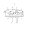
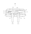
- the thermally responsive switch 1 includes a metal housing 2 and a lid plate 3 that form an airtight container.
- the housing 2 has a long dome shape with one end opened.
- the cover plate 3 is airtightly fixed to the opening end of the housing 2 by welding or the like.
- Metal conductive terminal pins 4 ⁇ / b> A and 4 ⁇ / b> B are inserted into two through holes provided in the cover plate 3.
- the conductive terminal pins 4A and 4B are fixed by an electrically insulating filler such as glass. As a result, the conductive terminal pins 4A and 4B are hermetically fixed in an electrically insulated state.
- a fixed contact 6A is fixed to a portion of one conductive terminal pin 4A on the inner side of the hermetic container via a conductive fixed contact support 6B.
- a thermally responsive plate 9 made of, for example, bimetal or trimetal is fixed to the inside of the housing 2 via a connection body 10.
- the thermally responsive plate 9 is formed by drawing into a dish shape, and one end thereof is connected to the inner surface of the housing 2 via the connection body 10. When the thermally responsive plate 9 reaches a predetermined temperature, its bending direction is reversed.
- a movable contact 8 is fixed to a movable end that is the other end of the thermally responsive plate 9.
- the movable contact 8 moves away from the fixed contact 6A when the thermally responsive plate 9 is reversed. As a result, the gap between the movable contact 8 and the fixed contact 6A is opened, and the conductive terminal pin 4B-heater 7-lid plate 3-housing 2-connector 10-thermally responsive plate 9-movable contact 8-fixed contact 6A-
- the electric circuit composed of the fixed contact support 6B and the conductive terminal pin 4A is interrupted.
- the movable contact 8 In a normal state where the thermally responsive plate 9 is not reversed, the movable contact 8 is in contact with the fixed contact 6A, and forms the above-described electric circuit.
- the movable contact 8 opens and closes the electric circuit by being driven by the thermally responsive plate 9 and coming into contact with and dissociating from the fixed contact 6A.
- one end of the heater 7 is connected to a portion of the other conductive terminal pin 4 ⁇ / b> B that is on the inner side of the hermetic container.
- the other end of the heater 7 is connected to the inner surface of the lid plate 3.
- the shape of the heater 7 will be described with reference to FIGS. 4 and 5.
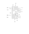
- the three-dimensional meandering heater 7 shown in FIG. 4 is manufactured by bending a meandering belt-shaped heater forming material with predetermined reference shafts 7Ha and 7Hb as creases as shown in FIG. Note that the heater forming material shown in FIG. 5 is obtained, for example, by punching a planar metal plate having a predetermined resistivity.
- the heater 7 has a configuration in which a part thereof is meandered and the meandered part is bent. That is, the heater 7 is composed of a plurality of heater units including a linear portion 7A that is a linear heating element and a semicircular portion 7B that is a semicircular heating element.
- the heater 7 connects a plurality of heater units alternately by connecting the linear portion 7A of one heater unit to the semicircular portion 7B of another heater unit.
- the heater 7 forms a plurality of meandering portions 7C and 7D in which the linear portion 7A is repeated via the semicircular portion 7B.
- the heater 7 has a structure in which a longer electric path is obtained in a limited space by meandering the heat generating elements.
- the meandering portions 7C and 7D are connected by a connecting portion 7E.
- the connecting portion 7E is a strip-like element extending linearly.
- the connecting portion 7E may meander.
- fixed portions 7F and 7G are provided at both ends of the heater 7.
- the meandering portions 7C and 7D are bent twice with respect to the predetermined first reference axis 7Ha and second reference axis 7Hb shown in FIG.
- the first reference shaft 7Ha and the second reference shaft 7Hb are both axes extending along the longitudinal direction of the long dome-shaped housing 2.
- the first reference shaft 7Ha is set outside the second reference shaft 7Hb in the width direction of the heater 7, and the second reference shaft 7Hb is set inside the first reference shaft 7Ha in the width direction of the heater 7. Is done.
- the second reference shaft 7Hb is set so as to sandwich the connection portion 7E outside the both ends of the connection portion 7E, and the first reference shaft 7Ha is located outside the second reference shaft 7Hb. Is set.
- the first reference shaft 7Ha and the second reference shaft 7Hb thus set are in a direction perpendicular to the direction in which the linear portion 7A extends and the direction in which the connection portion 7E connecting the meandering portions 7C and 7D extends. It becomes an extending axis.
- the heater unit of the portion facing the fixing portion 7F (the portion facing the conductive terminal pin 4B in a state of being attached in the airtight container) has a linear portion 7A that is a straight line of another heater unit. It is shorter than the shape portion 7A.
- the heater unit of the portion facing the fixed portion 7F (the portion facing the conductive terminal pin 4B in a state of being attached in the airtight container) has a linear portion 7A that is a straight line of another heater unit. It is shorter than the shape portion 7A.
- the meandering portions 7C and 7D are bent with respect to the first reference shaft 7Ha and the second reference shaft 7Hb so that one of the surfaces of the linear portion 7A faces each other. That is, the meandering portions 7C and 7D are configured to be bent 180 degrees at two locations with respect to the first reference shaft 7Ha and the second reference shaft 7Hb, respectively. In the meandering portions 7C and 7D bent in this way, a predetermined gap is formed between the same surfaces of the same linear portion 7A facing each other, that is, the inner surfaces in the bent state. Further, the meandering portions 7C and 7D are configured such that the belt-like flat portions constituting the linear portion 7A face each other.
- the meandering portions 7C and 7D are bent so that the extending direction of the linear portion 7A is perpendicular to the connecting portion 7E.
- the heater 7 is arrange
- the heater 7 is dimensioned in the width direction, which is a direction orthogonal to the first reference shaft 7Ha and the second reference shaft 7Hb, and a direction in which the connection portion 7E extends, by bending the meandering portions 7C, 7D in this way. Is suppressed. Therefore, the storage space of the heater 7 can be reduced, and the heater 7 can be placed in an airtight container having the same size as the conventional one while extending the entire length of the heater 7. Further, in the heater 7 in which the meandering portions 7C and 7D are bent as described above, the linear portion 7A of one meandering portion 7C and the linear portion 7A of the other meandering portion 7D face each other in the airtight container. Placed in. Further, the heater 7 is arranged in the airtight container so that the linear portion 7A of one meandering portion 7C is parallel to the linear portion 7A of the other meandering portion 7D.
- the heater 7 when the heater 7 is disposed in the hermetic container, the heater 7 surrounds the conductive terminal pin 4B by the fixing portion 7G-meandering portion 7C-connecting portion 7E-meandering portion 7D-fixing portion 7F. That is, the heater 7 is disposed so as to form a spiral around the conductive terminal pin 4B. Further, the heater 7 is arranged so that the meandering portions 7C and 7D face each other with the conductive terminal pin 4B interposed therebetween. The heater 7 is arranged such that the meandering portions 7C and 7D are parallel to the inner surface of the lid plate 3.
- the heater 7 is disposed such that the side surface which is the outside of the meandering portions 7 ⁇ / b> C and 7 ⁇ / b> D is along the inner peripheral surface of the housing 2.
- fixed part 7G used as the edge part of the peripheral side of the heater 7 is fixed to the inner surface of the cover board 3 by welding.
- the fixing portion 7F which is the end portion on the center side of the heater 7 is fixed to the end portion in the hermetic container of the conductive terminal pin 4B by welding or the like.
- the heater 7 has the connecting portion 7E on the side of the thermally responsive plate 9, the bent portion closest to the connecting portion 7E on the side of the lid plate 3, and the next bent portion on the side of the thermally responsive plate 9. Arranged in a state. Thereby, in the state where the heater 7 is disposed in the hermetic container, the area of the portion that is on the side of the thermally responsive plate 9 is larger than the area of the portion that is on the side of the lid plate 3 opposite to the side of the thermally responsive plate 9. It is a configuration that increases.
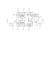
- the meandering portions 7 ⁇ / b> C and 7 ⁇ / b> D are bent twice with respect to the first reference shaft 7 ⁇ / b> Ha and the second reference shaft 7 ⁇ / b> Hb extending in the longitudinal direction of the housing 2.
- a plurality of inner vertical portions 72 and a plurality of intermediate vertical portions 73 are formed.
- the outer vertical portion 71 is a portion that is perpendicular to the inner surface of the cover plate 3 outside the first reference shaft 7Ha.
- the inner vertical portion 72 is a portion that is perpendicular to the inner surface of the cover plate 3 inside the second reference shaft 7Hb.
- the intermediate vertical portion 73 is a portion that is perpendicular to the inner surface of the cover plate 3 while being sandwiched between the outer vertical portion 71 and the inner vertical portion 72 between the first reference shaft 7Ha and the second reference shaft 7Hb. .
- the plurality of intermediate vertical portions 73 formed in the heater 7 can be classified into two types. That is, as shown in FIG. 6, one of the type A intermediate vertical portion 73 ⁇ / b> A in which another intermediate vertical portion 73 exists at both ends in the width direction of the intermediate vertical portion 73, and one of both ends in the width direction of the intermediate vertical portion 73. This is an intermediate vertical portion 73B of type B in which no other intermediate vertical portion 73 is present at the end portion.
- one type of heater 7 is formed with three type B intermediate vertical portions 73B. That is, an intermediate vertical portion 73B formed in the immediate vicinity of the fixed portion 7F and two intermediate vertical portions 73B formed at both ends of the connection portion 7E. And in the thermally responsive switch 1 which concerns on this embodiment, the special shape ingenuity is given to the intermediate
- FIG. 7 shows a part of the heater 7, particularly the vicinity of the fixed part 7 ⁇ / b> F. That is, the intermediate vertical portion 73B formed in the immediate vicinity of the fixing portion 7F is formed with a narrow portion 74 that functions as a fusing portion that is easier to blow than the other portions of the heater 7.
- the narrow portion 74 is a portion that is narrower than the width of the intermediate vertical portion 73B at the end of the intermediate vertical portion 73B in the width direction on the side where no other heat generating element exists. As shown in FIG. 3, a relatively wide space is secured on the end side where the narrow portion 74 is provided among the both ends of the intermediate vertical portion 73 in the sealed container of the thermally responsive switch 1. ing.
- the narrow portion 74 is provided so as to be biased toward the open end portion (the right end portion in FIG. 8) where no other heat generating element exists in the width direction of the intermediate vertical portion 73 ⁇ / b> B. . That is, the narrow portion 74 is provided at a position that is biased to the open side with respect to the center line CL in the width direction of the intermediate vertical portion 73B.
- a hollow 75 that is recessed in an arc toward the end on the side where no other heat generating elements are present. Is formed.
- the shape of the hollow part 75 is not restricted to circular arc shape.
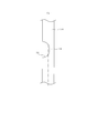
- the heater 7 has a narrow portion 76 between the fixed portion 7F that is an end portion connected to the conductive terminal pin 4B and the inner vertical portion 72 that faces the intermediate vertical portion 73B having the narrow portion 74. is doing.
- the width of the narrow portion 76 is smaller than at least the width of the inner vertical portion 72. Therefore, when the heater 7 starts from the fixed portion 7F, the heater 7 is once narrowed by the narrow portion 76, and then has a wide inner vertical portion 72.
- the intermediate vertical portion 73B following the inner vertical portion 72 has a narrow portion 74.
- the vertical dimension H1 of the inner vertical part 72 is shorter than the vertical dimension H2 of the intermediate vertical part 73 in this case.
- the heater 7 may have a configuration in which the vertical dimension of the outer vertical portion 71 is shorter than the vertical dimension of the intermediate vertical portion 73, or the outer vertical portion 71 and the inner vertical portion 72. Both vertical dimensions may be shorter than the vertical dimension of the intermediate vertical portion 73. That is, the heater 7 can be configured such that at least one of the outer vertical portion 71 and the inner vertical portion 72 is shorter than the intermediate vertical portion 73.
- the heating element of the heater 7 has meandering portions 7C and 7D made of a strip-shaped metal plate.
- the meandering portions 7C and 7D are bent twice with respect to the first reference shaft 7Ha and the second reference shaft 7Hb extending in the longitudinal direction of the housing 2, respectively, so that the cover plate is located outside the first reference shaft 7Ha. 3, an outer vertical portion 71 that is perpendicular to the inner surface of the cover plate 3, an inner vertical portion 72 that is perpendicular to the inner surface of the cover plate 3 on the inner side of the second reference shaft 7 Hb, the first reference shaft 7 Ha, and the second reference shaft.
- An intermediate vertical portion 73 that is perpendicular to the inner surface of the cover plate 3 while being sandwiched between the outer vertical portion 71 and the inner vertical portion 72 between the shaft 7Hb.
- the intermediate vertical portion 73B provided in the immediate vicinity of the fixed portion 7F is an open side where no other heat generating element is present at both ends in the width direction of the intermediate vertical portion 73B.
- the narrow vertical portion 74 is narrower than the width of the intermediate vertical portion 73B.
- the narrow portion 74 that functions as a fusing portion is provided at the open-side end portion where no other heat generating element is present, in both widthwise end portions of the intermediate vertical portion 73 ⁇ / b> B of the heater 7. It was. A relatively wide space is provided at the open end of the intermediate vertical portion 73B. According to this configuration, the spatter generated when the narrow portion 74 is melted is scattered toward a relatively wide space where there is no other heat generating element of the heater 7. Therefore, even if an arc is generated by sputtering, the arc can be extinguished before being transferred to another part, for example, the housing 2 or the cover plate 3, and the energization can be cut off.
- the heater 7 there are three type B intermediate vertical portions 73 ⁇ / b> B in which no other intermediate vertical portion 73 exists at one end portion of both ends in the width direction of the intermediate vertical portion 73, as shown in FIG. 6. .
- the two intermediate vertical portions 73B other than the intermediate vertical portion 73B closest to the fixing portion 7F are present at positions close to the thermally responsive plate 9. Therefore, if the narrow portion 74 having a relatively large calorific value is formed in the two intermediate vertical portions 73B, the transfer of heat from the heater 7 to the heat responsive plate 9 is affected, and thus the operation is stabilized. May affect sex.
- the narrow portion 74 is formed in the intermediate vertical portion 73B that is farthest from the thermally responsive plate 9. Therefore, it can be avoided that the operation becomes unstable with the formation of the narrow portion 74.
- the heater 7 meanders a band-shaped metal plate to form meandering portions 7C and 7D, and the meandering portions 7C and 7D are based on two reference shafts 7Ha and 7Hb. As shown in FIG. Therefore, in particular, the structure is such that heat tends to be trapped in the intermediate vertical portion 73 portion sandwiched between the outer vertical portion 71 and the inner vertical portion 72. According to the thermally responsive switch 1, the heater 7 has the vertical dimension of the inner vertical part 72 shorter than the vertical dimension of the intermediate vertical part 73.
- middle vertical part 73 can be decreased, in other words, the open area of the intermediate
- vertical part 73 part can be improved, it can prevent that the intermediate
- the heater 7 has a narrower portion 76 thinner than the inner vertical portion 72 between the fixed portion 7 ⁇ / b> F connected to the conductive terminal pin 4 ⁇ / b> B and the inner vertical portion 72. According to this structure, it can prevent that the heat
- the heater 7 is required to generate heat according to the magnitude of the current flowing through the heater 7. However, if heat escapes from the fixing portion 7F to the conductive terminal pin 4B side, the temperature of the inner vertical portion 72 may become too low.
- the heat of the inner vertical portion 72 including the narrow portion 74 is provided by increasing the amount of heat generated in the vicinity of the fixed portion 7F by providing the thin thin portion 76. Made it difficult to escape to the conductive terminal pin 4B side. Therefore, the heat generation property of the heater 7 according to the magnitude of the flowing current can be maintained.
- the meandering portion provided in the heater is not limited to two, and the number of the meandering portions can be changed as appropriate.
Abstract
Description
Claims (4)
- 金属製の長尺なドーム状に形成されたハウジングの開口端に蓋板を気密に固着することにより構成された気密容器と、
前記蓋板に設けられた2つの貫通孔にそれぞれ挿通され、それぞれ電気絶縁性の充填材によって気密に固定された2つの導電端子ピンと、
前記気密容器内において、一方の前記導電端子ピンに固定された固定接点と、
前記気密容器内において、一端が他方の前記導電端子ピンに接続され、他端が前記蓋板に接続されたヒータと、
一端が前記ハウジングの内面に接続され、所定の温度でその湾曲方向が反転する熱応動板と、
前記熱応動板の他端に設けられ、前記固定接点とともに一対の開閉接点を構成する可動接点と、を備える熱応動開閉器であって、
前記ヒータの発熱要素は、帯状の金属板からなる蛇行部を有し、
前記蛇行部は、前記ハウジングの長手方向に延びる第1基準軸および第2基準軸を基準に2回折り曲げられることで、前記第1基準軸よりも外側において前記蓋板の内面に対して垂直となる外側垂直部と、前記第2基準軸よりも内側において前記蓋板の内面に対して垂直となる内側垂直部と、前記第1基準軸と前記第2基準軸との間において前記外側垂直部と前記内側垂直部に挟まれた状態で前記蓋板の内面に対して垂直となる中間垂直部と、を有し、
前記中間垂直部は、当該中間垂直部の幅方向の両端部のうち他の前記発熱要素が存在しない側の端部に、当該中間垂直部の幅よりも狭い幅狭部を有することを特徴とする熱応動開閉器。 An airtight container configured by airtightly fixing a cover plate to an opening end of a housing formed in a long metal dome shape;
Two conductive terminal pins respectively inserted into two through holes provided in the lid plate and hermetically fixed by an electrically insulating filler;
In the airtight container, a fixed contact fixed to one of the conductive terminal pins,
In the airtight container, a heater having one end connected to the other conductive terminal pin and the other end connected to the lid plate;
A thermally responsive plate whose one end is connected to the inner surface of the housing and whose bending direction is reversed at a predetermined temperature;
A thermally responsive switch provided with the other end of the thermally responsive plate, and a movable contact that constitutes a pair of switching contacts together with the fixed contact;
The heating element of the heater has a meandering portion made of a strip-shaped metal plate,
The meandering portion is bent twice with respect to the first reference axis and the second reference axis extending in the longitudinal direction of the housing, so that the meandering portion is perpendicular to the inner surface of the lid plate outside the first reference axis. An outer vertical portion, an inner vertical portion perpendicular to the inner surface of the cover plate on the inner side of the second reference axis, and the outer vertical portion between the first reference axis and the second reference axis. And an intermediate vertical portion that is perpendicular to the inner surface of the lid plate in a state sandwiched between the inner vertical portions,
The intermediate vertical portion has a narrow portion narrower than the width of the intermediate vertical portion at an end portion on the side where the other heating element does not exist among both end portions in the width direction of the intermediate vertical portion. Thermally responsive switch. - 前記外側垂直部および前記内側垂直部の少なくとも一方は、前記中間垂直部よりも短いことを特徴とする請求項1に記載の熱応動開閉器。 The thermally responsive switch according to claim 1, wherein at least one of the outer vertical portion and the inner vertical portion is shorter than the intermediate vertical portion.
- 前記ヒータは、前記導電端子ピンに接続される端部と前記内側垂直部との間に、前記内側垂直部よりも細い細状部を有することを特徴とする請求項1または2に記載の熱応動開閉器。 3. The heat according to claim 1, wherein the heater has a narrower portion than the inner vertical portion between an end portion connected to the conductive terminal pin and the inner vertical portion. Responsive switch.
- 前記中間垂直部は、複数設けられており、
前記幅狭部は、これら複数の中間垂直部のうち、前記導電端子ピンに接続される端部の直近に形成される中間垂直部に設けられている請求項1から3の何れか1項に記載の熱応動開閉器。 A plurality of the intermediate vertical portions are provided,
The narrow portion is provided in an intermediate vertical portion formed in the immediate vicinity of an end connected to the conductive terminal pin among the plurality of intermediate vertical portions. The thermally responsive switch described.
Priority Applications (10)
| Application Number | Priority Date | Filing Date | Title |
|---|---|---|---|
| BR112017013061-0A BR112017013061A2 (en) | 2014-12-24 | 2014-12-24 | Heat corresponding movement switch |
| KR1020177017685A KR101939006B1 (en) | 2014-12-24 | 2014-12-24 | Thermal response switch |
| JP2016565716A JP6413203B2 (en) | 2014-12-24 | 2014-12-24 | Thermally sensitive switch |
| EP14908957.5A EP3240006A4 (en) | 2014-12-24 | 2014-12-24 | Thermal response switch |
| MX2017008214A MX2017008214A (en) | 2014-12-24 | 2014-12-24 | Thermal response switch. |
| US15/539,036 US20170352510A1 (en) | 2014-12-24 | 2014-12-24 | Thermal response switch |
| CN201480084188.0A CN107112165A (en) | 2014-12-24 | 2014-12-24 | Thermal switch |
| SG11201705051XA SG11201705051XA (en) | 2014-12-24 | 2014-12-24 | Thermal response switch |
| PCT/JP2014/084082 WO2016103349A1 (en) | 2014-12-24 | 2014-12-24 | Thermal response switch |
| PH12017550032A PH12017550032A1 (en) | 2014-12-24 | 2017-06-23 | Thermal response switch |
Applications Claiming Priority (1)
| Application Number | Priority Date | Filing Date | Title |
|---|---|---|---|
| PCT/JP2014/084082 WO2016103349A1 (en) | 2014-12-24 | 2014-12-24 | Thermal response switch |
Publications (1)
| Publication Number | Publication Date |
|---|---|
| WO2016103349A1 true WO2016103349A1 (en) | 2016-06-30 |
Family
ID=56149449
Family Applications (1)
| Application Number | Title | Priority Date | Filing Date |
|---|---|---|---|
| PCT/JP2014/084082 WO2016103349A1 (en) | 2014-12-24 | 2014-12-24 | Thermal response switch |
Country Status (10)
| Country | Link |
|---|---|
| US (1) | US20170352510A1 (en) |
| EP (1) | EP3240006A4 (en) |
| JP (1) | JP6413203B2 (en) |
| KR (1) | KR101939006B1 (en) |
| CN (1) | CN107112165A (en) |
| BR (1) | BR112017013061A2 (en) |
| MX (1) | MX2017008214A (en) |
| PH (1) | PH12017550032A1 (en) |
| SG (1) | SG11201705051XA (en) |
| WO (1) | WO2016103349A1 (en) |
Citations (3)
| Publication number | Priority date | Publication date | Assignee | Title |
|---|---|---|---|---|
| JP2005240596A (en) * | 2004-02-24 | 2005-09-08 | Ubukata Industries Co Ltd | Protective device for electric compressor |
| JP2007115610A (en) * | 2005-10-24 | 2007-05-10 | Sankei Giken:Kk | Planar heating element |
| JP2014059968A (en) * | 2012-09-14 | 2014-04-03 | Ubukata Industries Co Ltd | Thermally-actuated switch for sealed motor compressor |
Family Cites Families (11)
| Publication number | Priority date | Publication date | Assignee | Title |
|---|---|---|---|---|
| US5221915A (en) * | 1991-05-24 | 1993-06-22 | Matsushita Electric Industrial Co., Ltd. | Thermal protector |
| JP3828476B2 (en) * | 2002-10-15 | 2006-10-04 | 株式会社センサータ・テクノロジーズジャパン | Non-energized sealed motor protector |
| JP5001279B2 (en) * | 2006-08-10 | 2012-08-15 | 株式会社生方製作所 | Thermally sensitive switch |
| BRPI0716646B1 (en) * | 2006-08-10 | 2018-07-31 | Ubukata Industries Co., Ltd. | THERMAL RESPONSE SWITCH |
| US8193770B2 (en) * | 2007-12-25 | 2012-06-05 | BYD Co. Ltd | Battery system for a vehicle having an over-current/over-temperature protective feature |
| BRPI0822256B1 (en) * | 2008-02-08 | 2018-10-09 | Ubukata Ind Co Ltd | thermal response switch |
| EP2282320A1 (en) * | 2009-08-01 | 2011-02-09 | Limitor GmbH | Bimetallic snap disc |
| US9169635B2 (en) * | 2012-08-30 | 2015-10-27 | Ronald Andrews | Apparatus to tie forms to existing structures |
| CN104919559B (en) * | 2013-01-21 | 2017-03-08 | 株式会社生方制作所 | Thermal switch and its height adjuster of manufacture method and moving contact |
| CN203150476U (en) * | 2013-03-12 | 2013-08-21 | 株式会社生方制作所 | Thermoswitch |
| WO2015177925A1 (en) * | 2014-05-23 | 2015-11-26 | 株式会社生方製作所 | Heat-reactive switch |
-
2014
- 2014-12-24 MX MX2017008214A patent/MX2017008214A/en unknown
- 2014-12-24 KR KR1020177017685A patent/KR101939006B1/en active IP Right Grant
- 2014-12-24 CN CN201480084188.0A patent/CN107112165A/en active Pending
- 2014-12-24 EP EP14908957.5A patent/EP3240006A4/en not_active Withdrawn
- 2014-12-24 WO PCT/JP2014/084082 patent/WO2016103349A1/en active Application Filing
- 2014-12-24 US US15/539,036 patent/US20170352510A1/en not_active Abandoned
- 2014-12-24 BR BR112017013061-0A patent/BR112017013061A2/en not_active Application Discontinuation
- 2014-12-24 SG SG11201705051XA patent/SG11201705051XA/en unknown
- 2014-12-24 JP JP2016565716A patent/JP6413203B2/en not_active Expired - Fee Related
-
2017
- 2017-06-23 PH PH12017550032A patent/PH12017550032A1/en unknown
Patent Citations (3)
| Publication number | Priority date | Publication date | Assignee | Title |
|---|---|---|---|---|
| JP2005240596A (en) * | 2004-02-24 | 2005-09-08 | Ubukata Industries Co Ltd | Protective device for electric compressor |
| JP2007115610A (en) * | 2005-10-24 | 2007-05-10 | Sankei Giken:Kk | Planar heating element |
| JP2014059968A (en) * | 2012-09-14 | 2014-04-03 | Ubukata Industries Co Ltd | Thermally-actuated switch for sealed motor compressor |
Non-Patent Citations (1)
| Title |
|---|
| See also references of EP3240006A4 * |
Also Published As
| Publication number | Publication date |
|---|---|
| CN107112165A (en) | 2017-08-29 |
| BR112017013061A2 (en) | 2018-01-02 |
| PH12017550032A1 (en) | 2018-01-15 |
| JPWO2016103349A1 (en) | 2017-10-05 |
| KR20170086646A (en) | 2017-07-26 |
| US20170352510A1 (en) | 2017-12-07 |
| EP3240006A1 (en) | 2017-11-01 |
| MX2017008214A (en) | 2017-10-06 |
| JP6413203B2 (en) | 2018-10-31 |
| EP3240006A4 (en) | 2018-08-08 |
| SG11201705051XA (en) | 2017-07-28 |
| KR101939006B1 (en) | 2019-01-15 |
Similar Documents
| Publication | Publication Date | Title |
|---|---|---|
| JP3828476B2 (en) | Non-energized sealed motor protector | |
| JP5281689B2 (en) | Thermal protector | |
| JPH10308150A (en) | Motor protector | |
| WO2014171515A1 (en) | Protective device | |
| WO2015029826A1 (en) | Protective device | |
| KR20000062162A (en) | Motor protector apparatus | |
| JP2002124172A (en) | Thermal protector | |
| JP6078859B2 (en) | Thermally responsive switch and manufacturing method thereof | |
| JP6413203B2 (en) | Thermally sensitive switch | |
| WO2015177925A1 (en) | Heat-reactive switch | |
| JP6644237B2 (en) | Thermo-responsive switch | |
| JP2018206732A (en) | breaker | |
| JP6103180B2 (en) | Thermally responsive switch for hermetic electric compressors | |
| JP3393981B2 (en) | Thermal protector | |
| CN102915875B (en) | Thermal response switch | |
| JP3849387B2 (en) | Thermal protector | |
| JP7406279B2 (en) | motor protector | |
| JP2016170861A (en) | Electric circuit switching device and electric circuit switching system | |
| JP3186253B2 (en) | Overload protection device | |
| KR101243712B1 (en) | An internal overload protector | |
| JPH0822757A (en) | Overload protective device | |
| WO2006072995A1 (en) | Motor protector with ptc | |
| JP2001312950A (en) | Thermal fuse having self-heating element and pack battery with the built-in thermal fuse | |
| KR20050094548A (en) | Bimetal plate laminated thereon positive temperature coefficient material layer and device of blocking over current in electrical circuit using the same |
Legal Events
| Date | Code | Title | Description |
|---|---|---|---|
| 121 | Ep: the epo has been informed by wipo that ep was designated in this application |
Ref document number: 14908957 Country of ref document: EP Kind code of ref document: A1 |
|
| ENP | Entry into the national phase |
Ref document number: 2016565716 Country of ref document: JP Kind code of ref document: A |
|
| WWE | Wipo information: entry into national phase |
Ref document number: MX/A/2017/008214 Country of ref document: MX |
|
| WWE | Wipo information: entry into national phase |
Ref document number: 15539036 Country of ref document: US |
|
| WWE | Wipo information: entry into national phase |
Ref document number: 11201705051X Country of ref document: SG Ref document number: 12017550032 Country of ref document: PH |
|
| NENP | Non-entry into the national phase |
Ref country code: DE |
|
| ENP | Entry into the national phase |
Ref document number: 20177017685 Country of ref document: KR Kind code of ref document: A |
|
| REEP | Request for entry into the european phase |
Ref document number: 2014908957 Country of ref document: EP |
|
| REG | Reference to national code |
Ref country code: BR Ref legal event code: B01A Ref document number: 112017013061 Country of ref document: BR |
|
| ENP | Entry into the national phase |
Ref document number: 112017013061 Country of ref document: BR Kind code of ref document: A2 Effective date: 20170619 |