WO2016101975A1 - A control panel assembly for an electrical household appliance - Google Patents
A control panel assembly for an electrical household appliance Download PDFInfo
- Publication number
- WO2016101975A1 WO2016101975A1 PCT/EP2014/079001 EP2014079001W WO2016101975A1 WO 2016101975 A1 WO2016101975 A1 WO 2016101975A1 EP 2014079001 W EP2014079001 W EP 2014079001W WO 2016101975 A1 WO2016101975 A1 WO 2016101975A1
- Authority
- WO
- WIPO (PCT)
- Prior art keywords
- sealing means
- panel assembly
- control panel
- light
- beam collector
- Prior art date
- Legal status (The legal status is an assumption and is not a legal conclusion. Google has not performed a legal analysis and makes no representation as to the accuracy of the status listed.)
- Ceased
Links
Images




Classifications
-
- D—TEXTILES; PAPER
- D06—TREATMENT OF TEXTILES OR THE LIKE; LAUNDERING; FLEXIBLE MATERIALS NOT OTHERWISE PROVIDED FOR
- D06F—LAUNDERING, DRYING, IRONING, PRESSING OR FOLDING TEXTILE ARTICLES
- D06F34/00—Details of control systems for washing machines, washer-dryers or laundry dryers
- D06F34/28—Arrangements for programme selection, e.g. control panels therefor; Arrangements for indicating programme parameters, e.g. the selected programme or its progress
- D06F34/34—Arrangements for programme selection, e.g. control panels therefor; Arrangements for indicating programme parameters, e.g. the selected programme or its progress characterised by mounting or attachment features, e.g. detachable control panels or detachable display panels
Definitions
- the present invention relates to a control panel assembly involving a sealing means functioning as a light carrier and a liquid leakage barrier to protect an electronic control card of an electrical household appliance.
- a washing machine usually accommodates the control panel units on the upper front face of the appliance.
- the control panels are designed in the manner to be facing the user.
- Light beams from a light source positioned on an electronic control card are directed to a single area on the control panel’s main body as an indicator of the specific function chosen by the user. This is accomplished by means of a beam collector portion positioned between the electronic control card and the main body. Beam collector portion having apertures therein directs the light beam to led apertures installed on the control panel body. The led apertures causes risk of liquid leakage and damage to the electronic circuit of the appliance.
- the electronic control card can be disposed behind a protective foil covering the same and preventing liquids to reach the electronic components of the control card.
- a separate housing can be used to enclose the electronic control card so as to protect the electronic components.
- a prior art publication in the technical field of the present invention may be referred to as CN203065828, which discloses a control panel and a washing machine.
- the control panel comprises a panel main body and keys.
- the panel main body is provided with mounting holes; the keys are inserted into the mounting holes.
- Water retaining rings are arranged on the reverse side of the panel main body; the mounting holes are surrounded by the water retaining rings.
- the keys are provided with ring-shaped water retaining slots; the outer rings of the keys are surrounded by the ring-shaped water retaining slots and the water retaining rings are inserted into the ring-shaped water retaining slots.
- the water retaining rings are arranged on the panel main body, the ring-shaped water retaining slots are formed in the corresponding keys and the water retaining rings are inserted into the ring-shaped water retaining slots, so that after penetrating from gaps between the mounting holes and the keys, water is stopped from flowing into an electric control board in the washing machine along the keys by the ring-shaped water retaining slots.
- the water in the ring-shaped water retaining slots can flow to the reverse side of the panel main body along the water retaining rings and be drained.
- the present invention therefore provides a household appliance control panel assembly with an electronic control card which is effectively protected against water intrusion as provided by the characterizing features defined in Claim 1 and subsequent Claims.
- Primary object of the present invention is to provide a light carrier and liquid leakage barrier preventing liquids reaching to an electronic control card of the appliance.
- the present invention relates to an electrical household appliance with a control panel assembly.
- a sealing means is provided to be put inside a beam collector, the latter having light channels surrounded by an outer housing in the form of a ring-like structure while the peripheral space around the light channel is occupied by a sealing means cell of the sealing means, therefore ensuring an improved sealing effect.
- the sealing means cells also comprise central apertures through which the light channels are longitudinally introduced to reach to a panel body’s outer surface.
- the sealing means and the beam collector establish a multi-axis engagement such that the two U-shaped body portions thereof interengage to provide a connection structure in which each part is fixed one with respect to another.
- a separator is provided in the form of a multiple-enclosure structure, each individual enclosure surrounding a light source while a respective light barrier horizontally extend proximate the light source.
- Figure 1 demonstrates a general perspective view of a control panel assembly in an unassembled manner according to the present invention.
- Figure 2 demonstrates a front view of a control panel assembly according to the present invention.
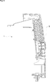
- Figure 3 demonstrates a cross-sectional view taken along line A-A of Fig. 2 according to the present invention.
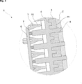
- Figure 4 demonstrates enlarged view of detail X of Fig. 3 according to the present invention.
- Figure 5 demonstrates a general perspective view of a beam collector according to the present invention.
- Figure 6 demonstrates a general perspective view of a sealing means according to the present invention.
- Figure 7 demonstrates a general perspective view of a separator according to the present invention.
- Figure 8 demonstrates a general perspective rear view of a panel body according to the present invention.
- the present invention relates to a control panel assembly (1) for an electrical household appliance such as a laundry washing machine, drying machine, washing/drying machine or a dishwasher, comprises a panel body (2) attached to an electronic control card (6) by means of a beam collector (4) in the inner area of the assembly.
- the beam collector (4) mounted directly behind a sealing means (3) providing protection to ensure impermeability against liquid passage and associated electronic card damages.
- the sealing means (3) is positioned behind the panel body (2) of the control panel assembly (1) while the beam collector (4) guide light beams to indicator openings (10) of the panel body (2).
- the present invention provides a control panel assembly (1) for an electrical household appliance comprising a sealing means (3) attached in the inner area of the panel body (2).
- the sealing means (3) performs as a barrier preventing liquid flow into the electronic control card (6) installed behind the beam collector (4), the latter transferring light beams from light sources (7) of the control card to the panel body (2) wall through apertures (14) of the sealing means (3).
- the sealing means (3) is attached directly behind the panel body (2) and is fitted into the beam collector (4) to guide light beams from light channels (8) of the beam collector (4) to the panel body (2) wall through the apertures (14) so that the indicator openings (10) on the panel body (2) are illuminated for indicating activation of a specific function.
- a plurality touch buttons (13) when pressed, transfer the applied force to switches (not shown) for instance in the form of tactile switches, of the electronic control card (6), upon which the function chosen by the user is executed.
- the sealing means (3) provides insulation for the electronic control card (6) against liquid passage from indicator openings (10) on the panel body (2).
- the sealing means (3) mates with the beam collector (4) in the manner that the apertures (14) thereof enclose light channels (8) of the beam collector (4) while a respective light channel (8) in each housing (9) of the beam collector (4) is peripherally covered by the sealing means (3) being inserted into the beam collector (4).
- the sealing means (3) and the beam collector (4) interengage such that no interspace is formed other than the light channel (8) apertures (14).
- the sealing means (3) has U-shaped portions (Fig. 4) in cross-section, engaging with U-shaped body portions of the beam collector (4) disposed between two vertically neighboring light channels (8).
- the engagement relationship of the sealing means (3) and the beam collector (4) is seen in Fig. 4 and the U-shaped body portions of the beam collector can be seen in Fig. 5.
- the insulation is ensured by an impermeability region (11) formed by the sealing means (3) enclosing the light channels (8). While the apertures (14) of the sealing means (3) receive the light channels (8), the latter extend therethrough outwardly towards the panel body (2) wall. Therefore, the impermeability region (11) resulted from the tight-fit connection of the sealing means (3), entirely insulating the beam collector (4) with the exception of the light channels (8), prevents liquid flow from indicator openings (10) into the inner side of the panel body (2).
- the beam collector (4) guiding the light beams from light sources (7) positioned on the electronic control card (6) towards the corresponding indicator openings (10) on the panel body (2) when a specific function of the appliance is activated by the user, additionally functions as a housing for touch buttons (13).
- the light channels (8) of the beam collector (4) assist to transfer of the light beams on a longitudinal path.
- the sealing means (3) enclosing the light channels (8) additionally ensures direct transfer of the light beams without reflections along other portions of the surface area of the panel body (2), because it eliminates light leakage between its front and rear sides; so the light beams are conveyed to the outer wall of the panel body (2) without leakage.
- the present invention proposes a separator (5) positioned directly in front of the electronic control card (6) and effective in preventing reflections at the inner surface of the electronic control card (6).
- the light beams from the light sources (7) of the electronic control card (6) are also encircled by respective enclosures (16) of the separator (5).
- the separator (5) features light barriers (15) within each enclosure (16) such that two light barriers (15) extend around a given light channel (8) at both vertical sides thereof, therefore serving for preventing scattering of the light along other portions of the surface area of the panel body (2).
- the light channels (8) separated from each other by a light barrier (15) to prevent light leakage is advantageous as an additional measure because it might happen that light from the light sources (7) leaks out where the light channels (8) extend to the light sources (7).
- the enclosures (16) comprise side walls additionally provide that scattering of light beams on the horizontal axis is avoided.
- the separator (5) ensures that the light beams reach to the outer wall of the panel body (2) without reflections. This is very important as the light beams traveling in between should not be allowed to scatter, which may severe effects on the illuminated areas on the panel body (2).
- the sealing means (3) provides the transfer of the light passed through the light channels (8) of the beam collector (4) to the indicator openings (10) of the panel body (2).
- the indicator openings (10) are separated from each other by antireflection plates (12) extending out from the panel body’s (2) inner wall preventing light leakage to neighboring indicator openings (10). Therefore only the specified button is indicated by illumination, when pressed.
- the present invention provides an electrical household appliance comprising a control panel assembly (1).
- the a control panel assembly (1) comprises a panel body (2) provided with a plurality of touch buttons (13) to effect control of the electrical household appliance, the touch buttons (13) being pressed to interact with an electronic control card (6).
- a sealing means (3) is interposed between the panel body (2) and the electronic control card (6), the sealing means (3) being inserted into a beam collector (4) receiving light beams from the electronic control card (6) and conveying the same to the outer wall of the panel body (2) by means of light channels (8).
- the sealing means (3) inserted into the beam collector (4) while the latter functions as a light carrier in a sealed manner through the light channels (8) advantageously provides that light beams are effectively conveyed without reflections and also without compromising leakage-free operation of the electronic control card (6) due to the light channels (8).
- the sealing means (3) comprises a plurality of sealing means cells (17), each of which fitting into a housing (9) of the beam collector (4) to provide tight-fit contact therewith from inside.
- Each sealing means cell (17) of the sealing means (3) tightly fitted inside the respective housing (9) of the beam collector (4) provides an improved sealing effect because a plurality of reciprocating individual parts simultaneously establish tight-fit connections.
- the housing (9) encloses the light channel (8) extending out from the housing (9) to the outer wall of the panel body (2).
- the sealing means cells (17) comprise apertures (14) through which the light channels (8) of the beam collector (4) extend.
- the light channel (8) in the housing (9) of the beam collector (4) is peripherally covered by the sealing means cell (17).
- the light channels (8) therefore extend to the panel body (2) outer wall in a sealed manner. It is to be noted that the tight-fit relation between the sealing means cells (17) and the surrounding housings (9) also produce an improved sealing effect around the light channels (8).
- the sealing means (3) and the beam collector (4) cooperate such that a cross-axis engagement relationship is established.
- the multiple-axis engagement provides fixed relative positioning of the respective parts, which substantially contributes to the preservation of the tight-fit relation between each sealing means cells (17) and the surrounding housings (9) and therefore adds to the sealing effect.
- U-shaped portions of the sealing means (3) engage with corresponding U-shaped body portions of the beam collector (4).
- the sealing means (3) interengages with the beam collector (4) in regions between two vertically neighboring light channels (8).
- a separator (5) is interposed between the electronic control card (6) and the beam collector (4), the separator (5) comprising a plurality of light barriers (15) extending into the housings (9) of the beam collector (4).
- the light barriers (15) are effective in that scattering of the light beams immediately where the light channels (8) extend to collect the beams is avoided.
- the light channels (8) are peripherally surrounded by enclosures (16) of the separator (5). Apart from the light barriers (15), the enclosures (16) further improve light leakage prevention effect as a 360-degrees surrounding physical barrier.
- the panel body (2) comprises indicator openings (10) receiving the light from the apertures (14) of the sealing means (3).
- the indicator openings (10) are separated from each other by antireflection plates (12) extending out from the inner wall of the panel body (2).
- the sealing means (3) is made from a non-transparent material.
- the electrical household appliance is a laundry washing machine, drying machine, washing/drying machine or a dishwasher.
- the invention provides a control panel assembly (1) involving a sealing means (3) functioning as both a light carrier and an effective liquid leakage barrier to protect the electronic control card (6) of an electrical household appliance.
- the sealing means (3) inserted into the beam collector (4) while the latter functions as a light carrier in a sealed manner through the light channels (8) advantageously provides that light beams are effectively conveyed without reflections and also without compromising leakage-free operation of the electronic control card (6) due to the light channels (8).
Landscapes
- Engineering & Computer Science (AREA)
- Textile Engineering (AREA)
- Detail Structures Of Washing Machines And Dryers (AREA)
Abstract
The present invention relates to a control panel assembly (1) involving a sealing means (3) functioning as a light carrier and a liquid leakage barrier to protect an electronic control card (6) of an electrical household appliance. The present invention more particularly relates to an electrical household appliance comprising a control panel assembly (1). The control panel assembly (1) comprises a panel body (2) provided with a plurality of touch buttons (13) to effect control of the electrical household appliance and the touch buttons (13) being pressed to interact with an electronic control card (6).
Description
The present invention relates to a control panel assembly involving a sealing means functioning as a light carrier and a liquid leakage barrier to protect an electronic control card of an electrical household appliance.
Modern household appliances have different structural forms. A washing machine usually accommodates the control panel units on the upper front face of the appliance. For ease of access, the control panels are designed in the manner to be facing the user.
Light beams from a light source positioned on an electronic control card are directed to a single area on the control panel’s main body as an indicator of the specific function chosen by the user. This is accomplished by means of a beam collector portion positioned between the electronic control card and the main body. Beam collector portion having apertures therein directs the light beam to led apertures installed on the control panel body. The led apertures causes risk of liquid leakage and damage to the electronic circuit of the appliance.
To address the above mentioned risks, the electronic control card can be disposed behind a protective foil covering the same and preventing liquids to reach the electronic components of the control card. Or alternatively, a separate housing can be used to enclose the electronic control card so as to protect the electronic components. A prominent disadvantage lies in that additional costs and a more complicated manufacturing and mounting scheme is necessary.
A prior art publication in the technical field of the present invention may be referred to as CN203065828, which discloses a control panel and a washing machine. The control panel comprises a panel main body and keys. The panel main body is provided with mounting holes; the keys are inserted into the mounting holes. Water retaining rings are arranged on the reverse side of the panel main body; the mounting holes are surrounded by the water retaining rings. The keys are provided with ring-shaped water retaining slots; the outer rings of the keys are surrounded by the ring-shaped water retaining slots and the water retaining rings are inserted into the ring-shaped water retaining slots. The water retaining rings are arranged on the panel main body, the ring-shaped water retaining slots are formed in the corresponding keys and the water retaining rings are inserted into the ring-shaped water retaining slots, so that after penetrating from gaps between the mounting holes and the keys, water is stopped from flowing into an electric control board in the washing machine along the keys by the ring-shaped water retaining slots. The water in the ring-shaped water retaining slots can flow to the reverse side of the panel main body along the water retaining rings and be drained.
The present invention therefore provides a household appliance control panel assembly with an electronic control card which is effectively protected against water intrusion as provided by the characterizing features defined in Claim 1 and subsequent Claims.
Primary object of the present invention is to provide a light carrier and liquid leakage barrier preventing liquids reaching to an electronic control card of the appliance.
The present invention relates to an electrical household appliance with a control panel assembly. A sealing means is provided to be put inside a beam collector, the latter having light channels surrounded by an outer housing in the form of a ring-like structure while the peripheral space around the light channel is occupied by a sealing means cell of the sealing means, therefore ensuring an improved sealing effect.
The sealing means cells, on the other hand, also comprise central apertures through which the light channels are longitudinally introduced to reach to a panel body’s outer surface.
The sealing means and the beam collector establish a multi-axis engagement such that the two U-shaped body portions thereof interengage to provide a connection structure in which each part is fixed one with respect to another.
Further, a separator is provided in the form of a multiple-enclosure structure, each individual enclosure surrounding a light source while a respective light barrier horizontally extend proximate the light source.
Accompanying drawings are given solely for the purpose of exemplifying a control panel assembly, whose advantages over prior art were outlined above and will be explained in brief hereinafter.
The drawings are not meant to delimit the scope of protection as identified in the claims nor should they be referred to alone in an effort to interpret the scope identified in the claims without recourse to the technical disclosure in the description of the present invention.
Figure 1 demonstrates a general perspective view of a control panel assembly in an unassembled manner according to the present invention.
Figure 2 demonstrates a front view of a control panel assembly according to the present invention.
Figure 3 demonstrates a cross-sectional view taken along line A-A of Fig. 2 according to the present invention.
Figure 4 demonstrates enlarged view of detail X of Fig. 3 according to the present invention.
Figure 5 demonstrates a general perspective view of a beam collector according to the present invention.
Figure 6 demonstrates a general perspective view of a sealing means according to the present invention.
Figure 7 demonstrates a general perspective view of a separator according to the present invention.
Figure 8 demonstrates a general perspective rear view of a panel body according to the present invention.
The following numerals are assigned to different parts demonstrated in the drawings:
- Control panel assembly
- Panel body
- Sealing means
- Beam collector
- Separator
- Electronic control card
- Light source
- Light channel
- Housing
- Indicator opening
- Impermeability region
- Antireflection plate
- Touch button
- Aperture
- Light barrier
- Enclosure
- Sealing means cell
The present invention relates to a control panel assembly (1) for an electrical household appliance such as a laundry washing machine, drying machine, washing/drying machine or a dishwasher, comprises a panel body (2) attached to an electronic control card (6) by means of a beam collector (4) in the inner area of the assembly. The beam collector (4) mounted directly behind a sealing means (3) providing protection to ensure impermeability against liquid passage and associated electronic card damages. The sealing means (3) is positioned behind the panel body (2) of the control panel assembly (1) while the beam collector (4) guide light beams to indicator openings (10) of the panel body (2).
The present invention provides a control panel assembly (1) for an electrical household appliance comprising a sealing means (3) attached in the inner area of the panel body (2). The sealing means (3) performs as a barrier preventing liquid flow into the electronic control card (6) installed behind the beam collector (4), the latter transferring light beams from light sources (7) of the control card to the panel body (2) wall through apertures (14) of the sealing means (3).
The sealing means (3) is attached directly behind the panel body (2) and is fitted into the beam collector (4) to guide light beams from light channels (8) of the beam collector (4) to the panel body (2) wall through the apertures (14) so that the indicator openings (10) on the panel body (2) are illuminated for indicating activation of a specific function. On the other hand, a plurality touch buttons (13), when pressed, transfer the applied force to switches (not shown) for instance in the form of tactile switches, of the electronic control card (6), upon which the function chosen by the user is executed.
The sealing means (3) provides insulation for the electronic control card (6) against liquid passage from indicator openings (10) on the panel body (2). The sealing means (3) mates with the beam collector (4) in the manner that the apertures (14) thereof enclose light channels (8) of the beam collector (4) while a respective light channel (8) in each housing (9) of the beam collector (4) is peripherally covered by the sealing means (3) being inserted into the beam collector (4). The sealing means (3) and the beam collector (4) interengage such that no interspace is formed other than the light channel (8) apertures (14). The sealing means (3) has U-shaped portions (Fig. 4) in cross-section, engaging with U-shaped body portions of the beam collector (4) disposed between two vertically neighboring light channels (8). The engagement relationship of the sealing means (3) and the beam collector (4) is seen in Fig. 4 and the U-shaped body portions of the beam collector can be seen in Fig. 5.
The insulation is ensured by an impermeability region (11) formed by the sealing means (3) enclosing the light channels (8). While the apertures (14) of the sealing means (3) receive the light channels (8), the latter extend therethrough outwardly towards the panel body (2) wall. Therefore, the impermeability region (11) resulted from the tight-fit connection of the sealing means (3), entirely insulating the beam collector (4) with the exception of the light channels (8), prevents liquid flow from indicator openings (10) into the inner side of the panel body (2).
The beam collector (4) guiding the light beams from light sources (7) positioned on the electronic control card (6) towards the corresponding indicator openings (10) on the panel body (2) when a specific function of the appliance is activated by the user, additionally functions as a housing for touch buttons (13). The light channels (8) of the beam collector (4) assist to transfer of the light beams on a longitudinal path. The sealing means (3) enclosing the light channels (8) additionally ensures direct transfer of the light beams without reflections along other portions of the surface area of the panel body (2), because it eliminates light leakage between its front and rear sides; so the light beams are conveyed to the outer wall of the panel body (2) without leakage.
Further, the present invention proposes a separator (5) positioned directly in front of the electronic control card (6) and effective in preventing reflections at the inner surface of the electronic control card (6). The light beams from the light sources (7) of the electronic control card (6) are also encircled by respective enclosures (16) of the separator (5). The separator (5) features light barriers (15) within each enclosure (16) such that two light barriers (15) extend around a given light channel (8) at both vertical sides thereof, therefore serving for preventing scattering of the light along other portions of the surface area of the panel body (2). The light channels (8) separated from each other by a light barrier (15) to prevent light leakage is advantageous as an additional measure because it might happen that light from the light sources (7) leaks out where the light channels (8) extend to the light sources (7).
Moreover, the enclosures (16) comprise side walls additionally provide that scattering of light beams on the horizontal axis is avoided. In sum, the separator (5) ensures that the light beams reach to the outer wall of the panel body (2) without reflections. This is very important as the light beams traveling in between should not be allowed to scatter, which may severe effects on the illuminated areas on the panel body (2).
The sealing means (3) provides the transfer of the light passed through the light channels (8) of the beam collector (4) to the indicator openings (10) of the panel body (2). The indicator openings (10) are separated from each other by antireflection plates (12) extending out from the panel body’s (2) inner wall preventing light leakage to neighboring indicator openings (10). Therefore only the specified button is indicated by illumination, when pressed.
Consequently, the present invention provides an electrical household appliance comprising a control panel assembly (1). The a control panel assembly (1) comprises a panel body (2) provided with a plurality of touch buttons (13) to effect control of the electrical household appliance, the touch buttons (13) being pressed to interact with an electronic control card (6).
In one embodiment according to the present invention, a sealing means (3) is interposed between the panel body (2) and the electronic control card (6), the sealing means (3) being inserted into a beam collector (4) receiving light beams from the electronic control card (6) and conveying the same to the outer wall of the panel body (2) by means of light channels (8). The sealing means (3) inserted into the beam collector (4) while the latter functions as a light carrier in a sealed manner through the light channels (8) advantageously provides that light beams are effectively conveyed without reflections and also without compromising leakage-free operation of the electronic control card (6) due to the light channels (8).
In a further embodiment according to the present invention, the sealing means (3) comprises a plurality of sealing means cells (17), each of which fitting into a housing (9) of the beam collector (4) to provide tight-fit contact therewith from inside. Each sealing means cell (17) of the sealing means (3) tightly fitted inside the respective housing (9) of the beam collector (4) provides an improved sealing effect because a plurality of reciprocating individual parts simultaneously establish tight-fit connections.
In a further embodiment according to the present invention, the housing (9) encloses the light channel (8) extending out from the housing (9) to the outer wall of the panel body (2).
In a further embodiment according to the present invention, the sealing means cells (17) comprise apertures (14) through which the light channels (8) of the beam collector (4) extend.
In a further embodiment according to the present invention, the light channel (8) in the housing (9) of the beam collector (4) is peripherally covered by the sealing means cell (17). The light channels (8) therefore extend to the panel body (2) outer wall in a sealed manner. It is to be noted that the tight-fit relation between the sealing means cells (17) and the surrounding housings (9) also produce an improved sealing effect around the light channels (8).
In a further embodiment according to the present invention, the sealing means (3) and the beam collector (4) cooperate such that a cross-axis engagement relationship is established. The multiple-axis engagement provides fixed relative positioning of the respective parts, which substantially contributes to the preservation of the tight-fit relation between each sealing means cells (17) and the surrounding housings (9) and therefore adds to the sealing effect.
In a further embodiment according to the present invention, U-shaped portions of the sealing means (3) engage with corresponding U-shaped body portions of the beam collector (4). The inner side openings of the two U-shaped bodies interengaging such that the first vertically oriented body engages with the second horizontally oriented body, provides a reciprocal cross-axis interlocking.
In a further embodiment according to the present invention, the sealing means (3) interengages with the beam collector (4) in regions between two vertically neighboring light channels (8).
In a further embodiment according to the present invention, a separator (5) is interposed between the electronic control card (6) and the beam collector (4), the separator (5) comprising a plurality of light barriers (15) extending into the housings (9) of the beam collector (4). The light barriers (15) are effective in that scattering of the light beams immediately where the light channels (8) extend to collect the beams is avoided.
In a further embodiment according to the present invention, the light channels (8) are peripherally surrounded by enclosures (16) of the separator (5). Apart from the light barriers (15), the enclosures (16) further improve light leakage prevention effect as a 360-degrees surrounding physical barrier.
In a further embodiment according to the present invention, the panel body (2) comprises indicator openings (10) receiving the light from the apertures (14) of the sealing means (3).
In a further embodiment according to the present invention, the indicator openings (10) are separated from each other by antireflection plates (12) extending out from the inner wall of the panel body (2).
In a further embodiment according to the present invention, the sealing means (3) is made from a non-transparent material.
In a further embodiment according to the present invention, the electrical household appliance is a laundry washing machine, drying machine, washing/drying machine or a dishwasher.
Therefore, the invention provides a control panel assembly (1) involving a sealing means (3) functioning as both a light carrier and an effective liquid leakage barrier to protect the electronic control card (6) of an electrical household appliance. The sealing means (3) inserted into the beam collector (4) while the latter functions as a light carrier in a sealed manner through the light channels (8) advantageously provides that light beams are effectively conveyed without reflections and also without compromising leakage-free operation of the electronic control card (6) due to the light channels (8).
Claims (14)
- A control panel assembly (1) for an electrical household appliance, comprising a panel body (2) provided with a plurality of touch buttons (13) to effect control of the electrical household appliance, the touch buttons (13) being pressed to interact with an electronic control card (6), characterized in thata sealing means (3) is interposed between the panel body (2) and the electronic control card (6), the sealing means (3) being inserted into a beam collector (4) receiving light beams from the electronic control card (6) and conveying the same to the outer wall of the panel body (2) by means of light channels (8).
- The control panel assembly (1) as in Claim 1, characterized in that the sealing means (3) comprising a plurality of sealing means cells (17), each of which fitting into a housing (9) of the beam collector (4) to provide tight-fit contact therewith from inside.
- The control panel assembly (1) as in Claim 2, characterized in that the housing (9) encloses the light channel (8) extending out from the housing (9) to the outer wall of the panel body (2).
- The control panel assembly (1) as in Claim 2 or 3, characterized in that the sealing means cells (17) comprising apertures (14) through which the light channels (8) of the beam collector (4) extend.
- The control panel assembly (1) as in Claim 4, characterized in that the light channel (8) in the housing (9) of the beam collector (4) is peripherally covered by the sealing means cell (17).
- The control panel assembly (1) as in Claim 1, 2 or 4, characterized in that the sealing means (3) and the beam collector (4) cooperate such that a cross-axis engagement relationship is established.
- The control panel assembly (1) as in Claim 6, characterized in that U-shaped portions of the sealing means (3) engage with corresponding U-shaped body portions of the beam collector (4).
- The control panel assembly (1) as in Claim 7, characterized in that the sealing means (3) interengages with the beam collector (4) in regions between two vertically neighboring light channels (8).
- The control panel assembly (1) as in any preceding Claim, characterized in that a separator (5) is interposed between the electronic control card (6) and the beam collector (4), the separator (5) comprising a plurality of light barriers (15) extending into the housings (9) of the beam collector (4).
- The control panel assembly (1) as in Claim 9, characterized in that the light channels (8) are peripherally surrounded by enclosures (16) of the separator (5).
- The control panel assembly (1) as in Claim 4 or 6, characterized in that the panel body (2) comprising indicator openings (10) receiving the light from the apertures (14) of the sealing means (3).
- The control panel assembly (1) as in Claim 11, characterized in that the indicator openings (10) are separated from each other by antireflection plates (12) extending out from the inner wall of the panel body (2).
- The control panel assembly (1) as in Claim 1, characterized in that the sealing means (3) is made from a non-transparent material.
- An electrical household appliance as in any preceding Claims, characterized in that the electrical household appliance is a laundry washing machine, drying machine, washing/drying machine or a dishwasher.
Priority Applications (1)
| Application Number | Priority Date | Filing Date | Title |
|---|---|---|---|
| PCT/EP2014/079001 WO2016101975A1 (en) | 2014-12-22 | 2014-12-22 | A control panel assembly for an electrical household appliance |
Applications Claiming Priority (1)
| Application Number | Priority Date | Filing Date | Title |
|---|---|---|---|
| PCT/EP2014/079001 WO2016101975A1 (en) | 2014-12-22 | 2014-12-22 | A control panel assembly for an electrical household appliance |
Publications (1)
| Publication Number | Publication Date |
|---|---|
| WO2016101975A1 true WO2016101975A1 (en) | 2016-06-30 |
Family
ID=52144711
Family Applications (1)
| Application Number | Title | Priority Date | Filing Date |
|---|---|---|---|
| PCT/EP2014/079001 Ceased WO2016101975A1 (en) | 2014-12-22 | 2014-12-22 | A control panel assembly for an electrical household appliance |
Country Status (1)
| Country | Link |
|---|---|
| WO (1) | WO2016101975A1 (en) |
Cited By (4)
| Publication number | Priority date | Publication date | Assignee | Title |
|---|---|---|---|---|
| WO2018065202A1 (en) * | 2016-10-07 | 2018-04-12 | Arcelik Anonim Sirketi | A household appliance with a control panel assembly |
| CN111764106A (en) * | 2019-03-12 | 2020-10-13 | 青岛海尔滚筒洗衣机有限公司 | a washing machine |
| IT202200000200A1 (en) * | 2022-01-10 | 2023-07-10 | Sonus Faber S P A | METHOD FOR CREATING A USER INTERFACE PANEL FOR ELECTRONIC DEVICES |
| US12495946B2 (en) | 2022-12-28 | 2025-12-16 | Whirlpool Corporation | Household appliance with a user interface |
Citations (3)
| Publication number | Priority date | Publication date | Assignee | Title |
|---|---|---|---|---|
| DE102006026910A1 (en) * | 2006-06-09 | 2007-12-13 | BSH Bosch und Siemens Hausgeräte GmbH | Operating unit for a household appliance |
| WO2011144484A1 (en) * | 2010-05-18 | 2011-11-24 | BSH Bosch und Siemens Hausgeräte GmbH | Display device of domestic appliance |
| EP2581025A1 (en) * | 2011-10-12 | 2013-04-17 | Samsung Electronics Co., Ltd | Control panel assembly and washing machine having the same |
-
2014
- 2014-12-22 WO PCT/EP2014/079001 patent/WO2016101975A1/en not_active Ceased
Patent Citations (3)
| Publication number | Priority date | Publication date | Assignee | Title |
|---|---|---|---|---|
| DE102006026910A1 (en) * | 2006-06-09 | 2007-12-13 | BSH Bosch und Siemens Hausgeräte GmbH | Operating unit for a household appliance |
| WO2011144484A1 (en) * | 2010-05-18 | 2011-11-24 | BSH Bosch und Siemens Hausgeräte GmbH | Display device of domestic appliance |
| EP2581025A1 (en) * | 2011-10-12 | 2013-04-17 | Samsung Electronics Co., Ltd | Control panel assembly and washing machine having the same |
Cited By (4)
| Publication number | Priority date | Publication date | Assignee | Title |
|---|---|---|---|---|
| WO2018065202A1 (en) * | 2016-10-07 | 2018-04-12 | Arcelik Anonim Sirketi | A household appliance with a control panel assembly |
| CN111764106A (en) * | 2019-03-12 | 2020-10-13 | 青岛海尔滚筒洗衣机有限公司 | a washing machine |
| IT202200000200A1 (en) * | 2022-01-10 | 2023-07-10 | Sonus Faber S P A | METHOD FOR CREATING A USER INTERFACE PANEL FOR ELECTRONIC DEVICES |
| US12495946B2 (en) | 2022-12-28 | 2025-12-16 | Whirlpool Corporation | Household appliance with a user interface |
Similar Documents
| Publication | Publication Date | Title |
|---|---|---|
| JP5024261B2 (en) | Washing machine | |
| KR20160008174A (en) | Explosion-protected arrangement of electrical and/or electronic components | |
| WO2016101971A1 (en) | A waterproof control panel assembly for an electrical household appliance | |
| CN102263380B (en) | There is the electric switchgear panel of the arc protection assembly of improvement | |
| EP2804453B1 (en) | Electronic device enclosure and electronic device | |
| CN110120609A (en) | Cable in connectors shell mitigates tension and shielding attachment | |
| JP2015220124A (en) | connector | |
| JP2015095384A (en) | Terminal block module | |
| KR200465224Y1 (en) | Consolidation cabinet panel | |
| WO2017005306A1 (en) | Improved control panel assembly for electrical household appliance | |
| CN208387132U (en) | A kind of anti-interference electrical assembly cabinet | |
| WO2018083067A1 (en) | A household appliance comprising a waterproof control panel assembly | |
| CN106489185A (en) | There is the user interface of the electronics of screening arrangement | |
| EP3149235B1 (en) | A household appliance comprising a front panel | |
| CN103998675A (en) | washing machine | |
| CN103682995A (en) | Cable distribution box with electric leakage detection function | |
| JP6171721B2 (en) | Power storage device | |
| ITMI981279A1 (en) | DEVICE FOR CABLE TIGHTENING AND DRAINAGE TOWARDS THE EDGE CURRENTS INDUCED ON SHIELDED CABLES WHEN CROSSING A | |
| EP2797476B1 (en) | A household appliance | |
| CN211829639U (en) | Power distribution cabinet with shielding function | |
| KR102631958B1 (en) | Safe power distribution box to prevent secondary accidents | |
| AU2013329750A1 (en) | Dishwasher with improved leak-proofing | |
| CN218352933U (en) | Waterproof structure of strong electric area of driving simulator and driving simulator | |
| KR101629739B1 (en) | Hatch vent for vessel | |
| CN218525214U (en) | Circuit assembly arrangement structure of driving simulator |
Legal Events
| Date | Code | Title | Description |
|---|---|---|---|
| 121 | Ep: the epo has been informed by wipo that ep was designated in this application |
Ref document number: 14816296 Country of ref document: EP Kind code of ref document: A1 |
|
| NENP | Non-entry into the national phase |
Ref country code: DE |
|
| 122 | Ep: pct application non-entry in european phase |
Ref document number: 14816296 Country of ref document: EP Kind code of ref document: A1 |