WO2016098559A1 - Grommet and electric wire with grommet - Google Patents
Grommet and electric wire with grommet Download PDFInfo
- Publication number
- WO2016098559A1 WO2016098559A1 PCT/JP2015/083333 JP2015083333W WO2016098559A1 WO 2016098559 A1 WO2016098559 A1 WO 2016098559A1 JP 2015083333 W JP2015083333 W JP 2015083333W WO 2016098559 A1 WO2016098559 A1 WO 2016098559A1
- Authority
- WO
- WIPO (PCT)
- Prior art keywords
- pair
- grommet
- arc
- inner peripheral
- portions
- Prior art date
Links
- 230000002093 peripheral effect Effects 0.000 claims description 95
- 230000004048 modification Effects 0.000 description 4
- 238000012986 modification Methods 0.000 description 4
- 239000002184 metal Substances 0.000 description 3
- 229920001971 elastomer Polymers 0.000 description 2
- XLYOFNOQVPJJNP-UHFFFAOYSA-N water Substances O XLYOFNOQVPJJNP-UHFFFAOYSA-N 0.000 description 2
- 238000004078 waterproofing Methods 0.000 description 2
- 239000002390 adhesive tape Substances 0.000 description 1
- 239000000806 elastomer Substances 0.000 description 1
- 238000009429 electrical wiring Methods 0.000 description 1
- 230000008595 infiltration Effects 0.000 description 1
- 238000001764 infiltration Methods 0.000 description 1
- 238000000034 method Methods 0.000 description 1
- 239000000203 mixture Substances 0.000 description 1
- 239000013307 optical fiber Substances 0.000 description 1
- 239000013585 weight reducing agent Substances 0.000 description 1
Images


Classifications
-
- B—PERFORMING OPERATIONS; TRANSPORTING
- B60—VEHICLES IN GENERAL
- B60R—VEHICLES, VEHICLE FITTINGS, OR VEHICLE PARTS, NOT OTHERWISE PROVIDED FOR
- B60R16/00—Electric or fluid circuits specially adapted for vehicles and not otherwise provided for; Arrangement of elements of electric or fluid circuits specially adapted for vehicles and not otherwise provided for
- B60R16/02—Electric or fluid circuits specially adapted for vehicles and not otherwise provided for; Arrangement of elements of electric or fluid circuits specially adapted for vehicles and not otherwise provided for electric constitutive elements
-
- H—ELECTRICITY
- H02—GENERATION; CONVERSION OR DISTRIBUTION OF ELECTRIC POWER
- H02G—INSTALLATION OF ELECTRIC CABLES OR LINES, OR OF COMBINED OPTICAL AND ELECTRIC CABLES OR LINES
- H02G3/00—Installations of electric cables or lines or protective tubing therefor in or on buildings, equivalent structures or vehicles
- H02G3/22—Installations of cables or lines through walls, floors or ceilings, e.g. into buildings
-
- B—PERFORMING OPERATIONS; TRANSPORTING
- B60—VEHICLES IN GENERAL
- B60R—VEHICLES, VEHICLE FITTINGS, OR VEHICLE PARTS, NOT OTHERWISE PROVIDED FOR
- B60R16/00—Electric or fluid circuits specially adapted for vehicles and not otherwise provided for; Arrangement of elements of electric or fluid circuits specially adapted for vehicles and not otherwise provided for
- B60R16/02—Electric or fluid circuits specially adapted for vehicles and not otherwise provided for; Arrangement of elements of electric or fluid circuits specially adapted for vehicles and not otherwise provided for electric constitutive elements
- B60R16/0207—Wire harnesses
- B60R16/0215—Protecting, fastening and routing means therefor
- B60R16/0222—Grommets
-
- F—MECHANICAL ENGINEERING; LIGHTING; HEATING; WEAPONS; BLASTING
- F16—ENGINEERING ELEMENTS AND UNITS; GENERAL MEASURES FOR PRODUCING AND MAINTAINING EFFECTIVE FUNCTIONING OF MACHINES OR INSTALLATIONS; THERMAL INSULATION IN GENERAL
- F16L—PIPES; JOINTS OR FITTINGS FOR PIPES; SUPPORTS FOR PIPES, CABLES OR PROTECTIVE TUBING; MEANS FOR THERMAL INSULATION IN GENERAL
- F16L5/00—Devices for use where pipes, cables or protective tubing pass through walls or partitions
- F16L5/02—Sealing
-
- H—ELECTRICITY
- H01—ELECTRIC ELEMENTS
- H01B—CABLES; CONDUCTORS; INSULATORS; SELECTION OF MATERIALS FOR THEIR CONDUCTIVE, INSULATING OR DIELECTRIC PROPERTIES
- H01B17/00—Insulators or insulating bodies characterised by their form
- H01B17/56—Insulating bodies
- H01B17/58—Tubes, sleeves, beads, or bobbins through which the conductor passes
-
- H—ELECTRICITY
- H01—ELECTRIC ELEMENTS
- H01B—CABLES; CONDUCTORS; INSULATORS; SELECTION OF MATERIALS FOR THEIR CONDUCTIVE, INSULATING OR DIELECTRIC PROPERTIES
- H01B7/00—Insulated conductors or cables characterised by their form
- H01B7/17—Protection against damage caused by external factors, e.g. sheaths or armouring
- H01B7/28—Protection against damage caused by moisture, corrosion, chemical attack or weather
- H01B7/282—Preventing penetration of fluid, e.g. water or humidity, into conductor or cable
Definitions
- the present invention relates to a grommet mounted to a through hole formed in a panel or the like of a vehicle.
- a panel or the like of a vehicle is provided with a through hole for pulling the wire from one side to the other side of the panel, and water or the like penetrates through the through hole to protect the wire from the inner peripheral edge of the through hole.
- a grommet may be attached to prevent this.
- the outer peripheral shape of a groove part is formed in elliptical shape, and it is made that it becomes difficult to deform
- ribs are provided at the four corners of the groove of the oval shape, and the ribs reinforce the groove and make the rib in close contact with the through hole.
- the protrusion dimension of a rib differs in each part along the extension direction of a groove part, Moreover, the part which a rib contacts with a through-hole, and the bottom of a groove part directly It is difficult to ensure a stable water-repellency in the entire extending direction of the groove, because the rib is deformed following the deformation of the grommet itself due to the mixture of the portion in contact with the portion and the deformation of the grommet itself.
- the 1st mode is a grommet attached to a track-shaped through hole formed in a panel of vehicles, and the cylinder part by which an electric wire is penetrated inside, and the perimeter of the cylinder part And a mounting portion having an annular groove formed on an outer peripheral portion thereof, the annular groove being capable of receiving the inner peripheral edge of the through hole, the bottom surface of the annular groove being a pair of straight portions; It is formed in the shape of an arc which becomes convex outward, and is formed in the track shape which has a pair of arc-like parts which connect each of the both ends of one side of the pair of straight parts and the both ends of the other side.
- the circumferential portion includes a portion whose thickness dimension gradually increases from the center of the pair of arcs toward the connecting portion between the pair of arcs and the pair of straight portions.
- a second aspect is the grommet according to the first aspect, wherein the inner peripheral surface of the inner peripheral side portion of the pair of linear portions is formed in a shape that describes an arc that is convex outward .
- a third aspect is the grommet according to the second aspect, wherein a thickness dimension of a central inner peripheral portion of the pair of linear portions is greater than a thickness dimension of a central inner peripheral portion of the pair of arc-shaped portions Is also a big one.
- a 4th aspect is a grommet which concerns on a 1st aspect, Comprising: The inner peripheral side part of a pair of said linear part is formed in the thickness direction uniform along the extension direction.
- a fifth aspect comprises the grommet according to any one of the first to fourth aspects, and at least one electric wire inserted into the cylindrical portion.
- the thickness dimension of the connecting portion between the inner peripheral side portion of the arc-shaped portion and the inner peripheral side portion of the linear portion is relatively large, and therefore it is difficult to bend at this portion.
- the straight portion is less likely to be deformed inward, and a gap is less likely to occur between the straight portion of the bottom surface of the annular groove and the inner peripheral edge portion of the through hole.
- the thickness dimension of the inner peripheral side portion at the center of the arc-shaped portion is relatively small, the force for shrinking the inner peripheral side portion of the annular groove in a state where the peripheral portion of the through hole is fitted into the annular groove is , Mainly absorbed in the middle of the arc.
- the arc-shaped portion itself is not easily deformed to the inside largely due to its shape, and therefore, the arc-shaped portion and the peripheral portion of the through hole can maintain a good contact state.
- the gap between the inner peripheral edge portion of the through hole and the bottom surface of the annular groove can be reduced as much as possible, and waterproofing between them can be improved.
- the inner peripheral surface of the inner peripheral side portion of the linear portion exhibits an arch structure, it is possible to suppress the deformation of the inner peripheral side portion of the linear portion while achieving weight reduction of the grommet.
- the deformation of the inner peripheral side portion of the straight portion can be more reliably suppressed.
- the inner circumferential portion of the straight portion has a thickness dimension substantially equal to the thickness dimension of the inner circumferential portion of the connection portion between the arc-shaped portion and the straight portion, and is uniform along the extending direction Since the thickness dimension is formed, the deformation of the inner peripheral side portion of the linear portion can be more reliably suppressed.
- FIG. 1 It is a perspective view showing a grommet concerning an embodiment. It is a schematic side view which shows the state in which the electric wire with a grommet was attached to the panel. It is explanatory drawing which shows the state which projected the cross-sectional shape of the mounting part on the peripheral part of the through-hole of a panel. It is sectional drawing which shows the mounting part which concerns on another example. It is explanatory drawing which shows the state which projected the cross-sectional shape of the mounting part which concerns on a modification on the peripheral part of the through-hole of a panel.
- FIG. 1 is a perspective view showing the grommet 20
- FIG. 2 is a schematic side view showing a state in which the grommet equipped electric wire 10 is mounted on the panel 16 (that is, a mounting structure of the grommet of the grommet equipped electric wire 10).
- FIG. 3 is a cross-sectional view of the mounting section 30 cut at a plane perpendicular to the central axis of the mounting section 30 (which coincides with the central axes of the cylindrical sections 22 and 24) and passing through the annular groove 40.
- a projected state is shown on the peripheral portion of the sixteen through holes 18. In this projection state, the center of the cross-sectional shape and the center of the through hole 18 coincide with each other.
- the grommet equipped electric wire 10 includes the electric wire 12 and the grommet 20.
- the grommet attached electric wire 10 includes a plurality of electric wires 12.
- the plurality of electric wires 12 are bundled so as to form a circular cross section at the portion where the grommet 20 is mounted.
- the plurality of wires 12 may be branched outside the grommet.
- a terminal is attached to the end of the wire 12 and the terminal is inserted and held in the connector.
- the connectors are connected to various electric parts mounted on the vehicle so that the various electric parts are electrically connected through the plurality of electric wires 12. Connected to That is, the grommet attached electric wire 10 is used as an electrical wiring member in a vehicle.
- the optical fiber cables may be bundled together in the electric wire 12. In FIG. 2, an outer shape in which a plurality of electric wires 12 are bundled is illustrated.
- the grommet 20 is a member which is inserted and mounted in the through hole 18 formed in the panel 16 of the vehicle.
- a metal plate that divides each part in a vehicle for example, a metal plate that divides an engine room and a vehicle compartment, a metal plate that divides a vehicle interior and the outside, and the like are assumed.
- the panel 16 is formed with a through hole 18 for passing the electric wire 12 therethrough.
- the through hole 18 is formed in a track shape.
- the track shape refers to a pair of straight lines disposed parallel to each other and at the positions where the ends are aligned in each extending direction, and an outer side connecting each one side end and the other side both ends of the pair of straight lines
- the arcs include arcs, but arcs are not required.
- the grommet 20 into which the electric wire 12 is inserted is inserted into the through hole 18 and mounted.
- the grommet 20 plays a role of protecting the electric wire 12 from the peripheral edge portion of the through hole 18 and suppressing the infiltration of water or the like from the space on one side of the panel 16 to the space on the other side.
- the grommet 20 is a member integrally molded with a mold using an elastomer such as rubber, and includes cylindrical portions 22 and 24 and a mounting portion 30.
- the cylinder part 22 is formed in the cylinder shape which can penetrate the electric wire 12 inside.
- the inner diameter of the cylindrical portion 22 is formed to have a size (slightly smaller) smaller than or equal to the outer diameter of the bundle of the plurality of electric wires 12. Then, in a state in which the cylindrical portion 22 is elastically deformed so as to expand in diameter, the bundle of the plurality of electric wires 12 is inserted and held therein.
- an adhesive tape or the like is wound around the end portion of the cylindrical portion 22 and the bundle of the plurality of electric wires 12 extending from the end portion.
- the cylindrical portion 24 is formed in a cylindrical shape in which the electric wire 12 can be inserted, similarly to the cylindrical portion 22.
- the cylindrical portions 22 and 24 extend on both sides of the mounting portion 30 and are coaxially disposed. Then, the bundle of the plurality of electric wires 12 is inserted from the cylindrical portion 22 into the cylindrical portion 24 through the inside of the mounting portion 30.
- One of the cylindrical portions 22 and 24 may be omitted.
- the mounting portion 30 is formed so as to protrude from the outer peripheral portion of the cylindrical portions 22 and 24.
- An annular groove 40 in which the inner peripheral edge portion of the through hole 18 can be fitted is formed on the outer peripheral portion. Further, in the mounting portion 30, a space connected to the cylindrical portions 22 and 24 is formed.
- the mounting portion 30 includes a collar portion 32 expanding outward from the end of the cylindrical portion 22, and a skirt portion 34 which sequentially expands from the outer peripheral portion of the collar portion 32 toward the cylindrical portion 24. And a connecting portion 36 connecting the skirt portion 34 and the collar portion 38.
- the collar portion 38 is expanded in diameter outward from the end of the cylindrical portion 24.
- the ridge portion 32 is formed in a track shape, and the edge of the widest portion of the skirt portion 34 also has a track shape. Further, the ridge portion 38 also has a track shape of the same size as or larger than the edge of the widest portion of the skirt portion 34.
- the connecting portion 36 also has a track shape smaller than the edge of the widest portion of the skirt 34 and the outer peripheral edge of the ridge 38.
- the widest portion of the skirt 34 and the flange 38 are connected via the connecting portion 36, and the outer peripheral surface of the linking portion 36 is formed into an annular bottom surface between the skirt 34 and the ridge 38. 42, an annular groove 40 is formed in which the most wide portion of the skirt 34 and the opposing surface of the ridge 38 are annular side surfaces.
- the bottom surface 42 of the annular groove 40 is formed in a track shape. That is, the bottom surface 42 includes a pair of straight portions 42 a and a pair of arc-shaped portions 42 b.
- the pair of straight portions 42a are formed parallel to each other and at positions where their ends are aligned in their extending directions.
- one arc-shaped part 42b is formed in the arc shape which becomes convex outward, and has connected one side both ends of a pair of linear part 42a.
- the other arc-shaped portion 42 b is formed in an arc shape that is convex outward, and connects the other side ends of the pair of straight portions 42 a.
- the thickness dimension of the inner peripheral side portion (that is, the connecting portion 36) of the annular groove 40 in the mounting portion 30 is gradually increased from the central portion of the pair of arc shaped portions 42b toward the pair of arc shaped portions 42b and the pair of straight portions 42a. It is set to be large.
- the thickness dimension of the inner peripheral side portion of the pair of linear portions 42a is set to be uniform along the extending direction.
- the shape of the inner peripheral surface of the inner peripheral side portion of the annular groove 40 in the mounting portion 30 (that is, the shape of the inner peripheral surface of the connecting portion 36) draws a track shape smaller than the track shape of the bottom surface 42 There is.
- the thickness dimension of the inner peripheral side portion of the central portion of the pair of arc-shaped portions 42b is set to d1, which is the inner peripheral side portion of the end portion of the pair of arc-shaped portions 42b, a pair of arc-shaped portions 42b and a pair of linear portions
- the thickness dimension of each connecting portion with 42a is set to d2 (d1 ⁇ d2), and the thickness dimension of the inner peripheral portion of the pair of arc-shaped portions 42b is set so as to gradually increase from d1 to d2 It is done.
- the thickness dimension of the inner peripheral side portion of the pair of linear portions 42a maintains the thickness dimension d2 of the connection portion in the entire extension direction.
- the size of the track shape of the bottom surface 42 is smaller than the size of the track shape of the through hole 18.
- the size of the track shape of the bottom surface 42 is larger than the size of the track shape of the through hole 18 to the extent that each portion of the bottom surface 42 is positioned inside by a certain dimension in the entire circumferential direction of the track shape of the through hole 18 small.
- the gap between the inner peripheral edge of the through hole 18 and the bottom surface of the annular groove 40 can be reduced as much as possible.
- FIG. 4 is a cross-sectional view showing the case where the thickness dimension of the inner peripheral side portion of the bottom surface 242 of the annular groove in the mounting portion 230 corresponding to the mounting portion 30 is uniform in the entire circumferential direction.
- the entire bottom surface 242 of the annular groove is pushed inward.
- the inner peripheral side portion of the arc-shaped portion 242 b has an arc shape which is convex outward, it is difficult to be deformed to the inner peripheral side, and a good contact state with the inner peripheral edge portion of the through hole 18 is maintained.
- the inner peripheral side portion of the linear portion 242a has a linear shape, it may be deformed inward as shown by the linear portion 242Ba of the two-dot chain line in FIG. If this deformation state is examined in detail, the linear portion 242a is not deformed only at the middle portion in the extension direction but is deformed to the inner peripheral side from the connecting portion of the linear portion 242a and the arc-shaped portion 242b. It has been found.
- the thickness dimension of the inner peripheral side portion of the annular groove 40 in the mounting portion 30 is such that the central portion of the pair of arc-shaped portions 42b connects each of the pair of arc-shaped portions 42b and the pair of straight portions 42a It is set to become gradually larger toward the part. As a result, it becomes difficult to bend between the inner peripheral side portion of the arc-shaped portion 42b and the inner peripheral side portion of the linear portion 42a, and as a result, the inner peripheral side portion of the linear portion 42a also becomes difficult to deform inward. As a result, a gap is less likely to occur between the straight portion 42 a of the bottom surface 42 of the annular groove 40 and the inner peripheral edge portion of the through hole 18.
- the inner peripheral side portion of the annular groove 40 is contracted in a state where the inner peripheral edge portion of the through hole 18 is fitted into the annular groove 40.
- the force to be applied is absorbed mainly at the center of the arc 42b.
- the arc-shaped portion 42b itself has an arc shape that is convex outward, it is difficult to deform inward, and the arc-shaped portion 42b and the inner peripheral edge portion of the through hole 18 maintain a good contact state. Can.
- the gap between the inner peripheral edge portion of the through hole 18 and the bottom surface 42 can be reduced as much as possible, and waterproofing between them can be improved.
- the bottom surface 42 is formed in the same track shape as the through holes 18, it is difficult for the shape nonconformity to occur as in the case where the outer peripheral shape of the groove is elliptical as in the prior art. From this point as well, it is possible to improve the waterproofness between them.
- the inner circumferential side portion of the linear portion 42a is about the same as the thickness dimension d2 of the inner circumferential side portion of the connection portion between the arc-shaped portion 42b and the linear portion 42a, and has a uniform thickness dimension d2 along its extending direction. Since it is formed, the deformation of the inner peripheral side portion of the straight portion 42a can be suppressed more reliably.
- the thickness d2 of the inner peripheral portion of the straight portion 42a is set to be the same along the extending direction, but such a configuration is not necessarily required.
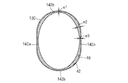
- the bottom surface 42 of the annular groove is formed in the same shape as the above embodiment, but the inner periphery of the bottom surface 42 of the mounting portion 130
- the shape of the inner peripheral surface of the side portion is formed in an elliptical shape (an elliptical shape defined mathematically).
- the thickness dimension of the pair of arc-shaped portions 142b corresponding to the pair of arc-shaped portions 42b is from the center of the arc-shaped portion 142b toward the connecting portion between the arc-shaped portion 142b and the linear portion 142a corresponding to the straight portion. Includes parts that grow gradually.
- the thickness dimension of the inner peripheral side portion of the central portion of the arc-shaped portion 142b is set to e1
- the thickness dimension of the portion closer to the arc-shaped portion 142 than each connecting portion of the arc-shaped portion 142b and the straight portion 142a is It is set to e2 (e1 ⁇ e2)
- the thickness dimension of the inner peripheral side portion of the arc-shaped portion 142b is set to gradually increase from e1 to e2.
- the inner peripheral surface of the inner peripheral side portion of the straight portion 142a draws an arc which is convex outward.
- the thickness dimension of the inner peripheral side portion of the middle portion in the extension direction of the straight portion 142a is e3 (e3 ⁇ e2). That is, the thickness dimension of the inner peripheral side portion of the end portion of the straight portion 142a is set so as to gradually decrease from the end portion toward the center.
- the thickness dimension e3 of the inner peripheral side portion at the center of the linear portion 142a is preferably larger than the thickness dimension e1 of the center of the arc-shaped portion 142b.
- the thickness dimension of the inner peripheral portion of the connection portion between the straight portion 142a and the arc-shaped portion 142b is relatively large, and the thickness dimension of the central inner peripheral portion of the arc-shaped portion 142b is relatively large.
- the gap between the inner peripheral edge portion of the through hole 18 and the bottom surface of the annular groove 40 can be reduced as much as possible, and the waterproofness between them can be improved.
- the inner peripheral side portion of the arc-shaped portion 142b may include a portion whose thickness dimension gradually increases from the center toward the end portion (connection portion), and the linear portion 142a and It is not necessary for the connecting portion with the arc-shaped portion 142b to be the thickest. That is, it may be formed so that the thickness dimension becomes the largest at the positions before and after the connecting portion within the range in which the inward deformation of the linear portion 142a can be suppressed.
- the inner peripheral surface of the inner peripheral side portion of the linear portion 142a is formed in a shape that draws an arc that is convex outward, the portion along the inner peripheral surface of the inner peripheral side portion of the linear portion 142a is Make a kind of arch structure. Therefore, it is possible to suppress the deformation of the inner peripheral side portion of the linear portion 142a while reducing the weight of the grommet 20, and to improve the waterproofness between the inner peripheral edge portion of the through hole 18 and the bottom surface of the annular groove 40 You can keep
Abstract
The purpose of the present invention is to improve, in a grommet to be fitted into a track-shaped through hole, a water-stopping property between an inner circumferential edge of the through hole and a bottom surface of a ring-shaped groove of the grommet. A grommet of the present invention comprises: a cylindrical part; and a fitting part that is formed so as to protrude to an outer circumferential part of the cylindrical part and that has formed, in an outer circumferential part thereof, a ring-shaped groove into which the inner circumferential edge of the through hole can be inserted. A bottom surface of the ring-shaped groove is formed in a track shape that has a pair of straight-line portions and a pair of arc-shaped portions that are each formed in an outwardly convex arc shape and that connect the two ends on one side of the pair of straight-line portions and the two ends on the other side of the pair of straight-line portions. An inner circumferential part of each arc-shaped portion includes a part having a thickness that gradually increases from the center thereof toward connecting parts between the arc-shaped portions and the straight-line portions.
Description
この発明は、車両のパネル等に形成された貫通孔に装着されるグロメットに関する。
The present invention relates to a grommet mounted to a through hole formed in a panel or the like of a vehicle.
車両のパネル等には、パネルに対して一方側から他方側に電線を引きこむための貫通孔が形成され、当該貫通孔の内周縁部から電線を保護するため及び貫通孔を通して水等が浸入することを抑制するため、グロメットが装着されることがある。
A panel or the like of a vehicle is provided with a through hole for pulling the wire from one side to the other side of the panel, and water or the like penetrates through the through hole to protect the wire from the inner peripheral edge of the through hole. A grommet may be attached to prevent this.
貫通孔がトラック形状に形成されると共に、グロメットの外周にも前記トラック形状に応じた溝が形成されている場合において、グロメットを貫通孔に取付けると、グロメットと貫通孔との間で隙間が生じ易いという問題がある。グロメットに形成された溝の直線部分が内側に撓み変形し易く、結果、その溝の直線部分と貫通孔の周縁部の直線部分との間で隙間が生じてしまうからである。
When the through hole is formed in a track shape and a groove corresponding to the track shape is also formed on the outer periphery of the grommet, when the grommet is attached to the through hole, a gap is generated between the grommet and the through hole There is a problem that it is easy. This is because the straight portion of the groove formed in the grommet tends to be bent and deformed inward, and as a result, a gap is generated between the straight portion of the groove and the straight portion of the peripheral portion of the through hole.
そこで、特許文献1では、溝部の外周形状を楕円形状に形成して、溝部が内側に変形し難くなるようにしている。また、溝部の楕円形状四隅にリブを設け、このリブによって溝部を補強すると共に、リブを貫通孔に密接させるようにしている。
So, in patent document 1, the outer peripheral shape of a groove part is formed in elliptical shape, and it is made that it becomes difficult to deform | transform a groove part inside. In addition, ribs are provided at the four corners of the groove of the oval shape, and the ribs reinforce the groove and make the rib in close contact with the through hole.
しかしながら、特許文献1に開示の技術によると、貫通孔の内周縁部形状と溝部の外周形状との整合性が悪く、貫通孔の内周縁部と溝部の底面との密着性が悪い部分が生じ得る。例えば、溝部のうち楕円の短軸方向両側の弧状部分と、楕円の長軸方向両側の弧状部分との連結部分で、貫通孔の内周縁部と溝部の底面との密着性が悪くなる恐れが懸念される。
However, according to the technique disclosed in Patent Document 1, the matching between the inner peripheral edge shape of the through hole and the outer peripheral shape of the groove portion is poor, and a portion where the adhesion between the inner peripheral edge of the through hole and the bottom surface of the groove portion is poor occurs. obtain. For example, there is a risk that the adhesion between the inner peripheral edge of the through hole and the bottom of the groove may deteriorate at the connection between the arc on both sides of the ellipse in the minor axis direction and the arc on both sides in the long axis of the ellipse. I am concerned.
また、特許文献1では、リブを設けているが、リブの突出寸法が溝部の延在方向に沿って各部で異なること、また、貫通孔に対してリブが接触する部分と溝部の底が直接的に接触する部分とが混在すること、グロメット自体の変形に追従してリブが変形してしまうこと等から、溝部の延在方向全体において安定した止水性を確保することは困難である。
Moreover, although the rib is provided in patent document 1, the protrusion dimension of a rib differs in each part along the extension direction of a groove part, Moreover, the part which a rib contacts with a through-hole, and the bottom of a groove part directly It is difficult to ensure a stable water-repellency in the entire extending direction of the groove, because the rib is deformed following the deformation of the grommet itself due to the mixture of the portion in contact with the portion and the deformation of the grommet itself.
そこで、本発明は、トラック形状の貫通孔に装着されるグロメットにおいて、貫通孔の内周縁部とグロメットの環状溝の底面との間の止水性の向上を図ることを目的とする。
Therefore, it is an object of the present invention to improve waterproofness between the inner peripheral edge portion of the through hole and the bottom surface of the annular groove of the grommet in the grommet attached to the track-shaped through hole.
上記課題を解決するため、第1の態様は、車両のパネルに形成されたトラック形状の貫通孔に装着されるグロメットであって、内部に電線が挿通される筒部と、前記筒部の外周部に突出するように形成されると共に、外周部に前記貫通孔の内周縁部を嵌め込み可能な環状溝が形成された装着部とを備え、前記環状溝の底面が、一対の直線部と、外向きに凸となる弧状に形成され、前記一対の直線部の一方側の両端及び他方側の両端のそれぞれを繋ぐ一対の弧状部とを有するトラック形状に形成され、前記一対の弧状部の内周側部分は、その厚み寸法が、前記一対の弧状部の中央から前記一対の弧状部と前記一対の直線部とのそれぞれの連結部分に向うに従って徐々に大きくなる部分を含む。
In order to solve the above-mentioned subject, the 1st mode is a grommet attached to a track-shaped through hole formed in a panel of vehicles, and the cylinder part by which an electric wire is penetrated inside, and the perimeter of the cylinder part And a mounting portion having an annular groove formed on an outer peripheral portion thereof, the annular groove being capable of receiving the inner peripheral edge of the through hole, the bottom surface of the annular groove being a pair of straight portions; It is formed in the shape of an arc which becomes convex outward, and is formed in the track shape which has a pair of arc-like parts which connect each of the both ends of one side of the pair of straight parts and the both ends of the other side. The circumferential portion includes a portion whose thickness dimension gradually increases from the center of the pair of arcs toward the connecting portion between the pair of arcs and the pair of straight portions.
第2の態様は、第1の態様に係るグロメットであって、前記一対の直線部の内周側部分の内周面が、外側に凸となる弧を描く形状に形成されているものである。
A second aspect is the grommet according to the first aspect, wherein the inner peripheral surface of the inner peripheral side portion of the pair of linear portions is formed in a shape that describes an arc that is convex outward .
第3の態様は、第2の態様に係るグロメットであって、前記一対の直線部の中央の内周側部分の厚み寸法が、前記一対の弧状部の中央の内周側部分の厚み寸法よりも大きいものである。
A third aspect is the grommet according to the second aspect, wherein a thickness dimension of a central inner peripheral portion of the pair of linear portions is greater than a thickness dimension of a central inner peripheral portion of the pair of arc-shaped portions Is also a big one.
第4の態様は、第1の態様に係るグロメットであって、前記一対の直線部の内周側部分がその延在方向に沿って均一な厚み寸法に形成されているものである。
A 4th aspect is a grommet which concerns on a 1st aspect, Comprising: The inner peripheral side part of a pair of said linear part is formed in the thickness direction uniform along the extension direction.
第5の態様は、第1~第4のいずれか1つの態様に係るグロメットと、前記筒部に挿通された少なくとも1本の電線とを備える。
A fifth aspect comprises the grommet according to any one of the first to fourth aspects, and at least one electric wire inserted into the cylindrical portion.
第1~第5の態様によると、弧状部の内周側部分と直線部の内周側部分との連結部分の厚み寸法が比較的大きいため、この部分で曲り難い。これにより、直線部が内側に変形し難くなり、環状溝の底面の直線部と貫通孔の内周縁部との間で隙間が生じ難くなる。また、弧状部の中央の内周側部分の厚み寸法が比較的小さいため、貫通孔の周縁部を環状溝に嵌め込んだ状態で、環状溝の内周側部分を収縮させようとする力は、主として弧状部の中央で吸収される。弧状部自体は、その形状からして内側に大きく変形し難く、従って、弧状部と貫通孔の周縁部とは、良好な接触状態を保つことができる。結果、環状溝の底面の周方向全体において、貫通孔の内周縁部と環状溝の底面との隙間をなるべく少なくすることができ、それらの間での止水性の向上を図ることができる。
According to the first to fifth aspects, the thickness dimension of the connecting portion between the inner peripheral side portion of the arc-shaped portion and the inner peripheral side portion of the linear portion is relatively large, and therefore it is difficult to bend at this portion. As a result, the straight portion is less likely to be deformed inward, and a gap is less likely to occur between the straight portion of the bottom surface of the annular groove and the inner peripheral edge portion of the through hole. Further, since the thickness dimension of the inner peripheral side portion at the center of the arc-shaped portion is relatively small, the force for shrinking the inner peripheral side portion of the annular groove in a state where the peripheral portion of the through hole is fitted into the annular groove is , Mainly absorbed in the middle of the arc. The arc-shaped portion itself is not easily deformed to the inside largely due to its shape, and therefore, the arc-shaped portion and the peripheral portion of the through hole can maintain a good contact state. As a result, in the entire circumferential direction of the bottom surface of the annular groove, the gap between the inner peripheral edge portion of the through hole and the bottom surface of the annular groove can be reduced as much as possible, and waterproofing between them can be improved.
第2の態様によると、直線部の内周側部分の内周面がアーチ構造を呈するため、グロメットの軽量化を図りつつ、直線部の内周側部分の変形を抑制できる。
According to the second aspect, since the inner peripheral surface of the inner peripheral side portion of the linear portion exhibits an arch structure, it is possible to suppress the deformation of the inner peripheral side portion of the linear portion while achieving weight reduction of the grommet.
第3の態様によると、直線部の内周側部分の変形をより確実に抑制できる。
According to the third aspect, the deformation of the inner peripheral side portion of the straight portion can be more reliably suppressed.
第4の態様によると、直線部の内周側部分が、弧状部と直線部との連結部分の内周側部分の厚み寸法と同程度の厚み寸法で、その延在方向に沿って均一な厚み寸法に形成されるため、直線部の内周側部分の変形をより確実に抑制できる。
According to the fourth aspect, the inner circumferential portion of the straight portion has a thickness dimension substantially equal to the thickness dimension of the inner circumferential portion of the connection portion between the arc-shaped portion and the straight portion, and is uniform along the extending direction Since the thickness dimension is formed, the deformation of the inner peripheral side portion of the linear portion can be more reliably suppressed.
以下、実施形態に係るグロメット及びグロメット付電線について説明する。図1はグロメット20を示す斜視図であり、図2はグロメット付電線10がパネル16に装着された状態(つまり、グロメット付電線10のグロメットの取付構造)を示す概略側面図である。また、図3は、装着部30をその中心軸(筒部22、24の中心軸と一致している)に対して直交し、かつ、環状溝40を通る平面で切断した断面形状を、パネル16の貫通孔18の周縁部に投影した状態を示している。なお、この投影状態において、断面形状の中心と貫通孔18の中心とは一致している。
Hereinafter, the grommet and the electric wire with the grommet according to the embodiment will be described. FIG. 1 is a perspective view showing the grommet 20, and FIG. 2 is a schematic side view showing a state in which the grommet equipped electric wire 10 is mounted on the panel 16 (that is, a mounting structure of the grommet of the grommet equipped electric wire 10). FIG. 3 is a cross-sectional view of the mounting section 30 cut at a plane perpendicular to the central axis of the mounting section 30 (which coincides with the central axes of the cylindrical sections 22 and 24) and passing through the annular groove 40. A projected state is shown on the peripheral portion of the sixteen through holes 18. In this projection state, the center of the cross-sectional shape and the center of the through hole 18 coincide with each other.
グロメット付電線10は、電線12と、グロメット20とを備える。
The grommet equipped electric wire 10 includes the electric wire 12 and the grommet 20.
ここでは、グロメット付電線10は、複数の電線12を含む。複数の電線12は、本グロメット20が装着される部分では、円形断面をなすように束ねられている。複数の電線12は、グロメット外で分岐していてもよい。電線12の端部には端子が取付けられており、端子はコネクタに挿入保持される。そして、本グロメット付電線10が、車両に配設された状態で、各コネクタが車両に搭載された各種電気部品にコネクタ接続されることにより、各種電気部品が複数の電線12を介して電気的に接続される。すなわち、本グロメット付電線10は、車両における電気的な配線材として用いられる。電線12には、光ファイバケーブルが一緒に束ねられていてもよい。図2では、複数の電線12が束ねられた外形が描かれている。
Here, the grommet attached electric wire 10 includes a plurality of electric wires 12. The plurality of electric wires 12 are bundled so as to form a circular cross section at the portion where the grommet 20 is mounted. The plurality of wires 12 may be branched outside the grommet. A terminal is attached to the end of the wire 12 and the terminal is inserted and held in the connector. Then, in a state where the grommet attached electric wire 10 is disposed in the vehicle, the connectors are connected to various electric parts mounted on the vehicle so that the various electric parts are electrically connected through the plurality of electric wires 12. Connected to That is, the grommet attached electric wire 10 is used as an electrical wiring member in a vehicle. The optical fiber cables may be bundled together in the electric wire 12. In FIG. 2, an outer shape in which a plurality of electric wires 12 are bundled is illustrated.
グロメット20は、車両のパネル16に形成された貫通孔18に挿入されて装着される部材である。
The grommet 20 is a member which is inserted and mounted in the through hole 18 formed in the panel 16 of the vehicle.
パネル16としては、車両における各部を仕切る金属板、例えば、エンジンルームと車室とを仕切る金属板、車室内と外部とを仕切る金属板等が想定される。
As the panel 16, a metal plate that divides each part in a vehicle, for example, a metal plate that divides an engine room and a vehicle compartment, a metal plate that divides a vehicle interior and the outside, and the like are assumed.
パネル16には、電線12を通すための貫通孔18が形成されている。貫通孔18は、トラック形状に形成されている。ここで、トラック形状とは、互いに平行でかつそれぞれの延在方向において端部を揃えた位置に配設された一対の直線と、一対の直線の一方側両端及び他方側両端のそれぞれを繋ぐ外向きに凸となる一対の弧とで規定される形状をいう。弧は、円弧を含むが、円弧であることは必須ではない。
The panel 16 is formed with a through hole 18 for passing the electric wire 12 therethrough. The through hole 18 is formed in a track shape. Here, the track shape refers to a pair of straight lines disposed parallel to each other and at the positions where the ends are aligned in each extending direction, and an outer side connecting each one side end and the other side both ends of the pair of straight lines A shape defined by a pair of arcs that are convex in the direction. The arcs include arcs, but arcs are not required.
そして、電線12が挿通されたグロメット20が上記貫通孔18に挿入されて装着される。これにより、グロメット20は、貫通孔18の周縁部から電線12を保護すると共に、パネル16の一方側空間から他方側空間へ水等が浸入することを抑制する役割を果す。
Then, the grommet 20 into which the electric wire 12 is inserted is inserted into the through hole 18 and mounted. Thereby, the grommet 20 plays a role of protecting the electric wire 12 from the peripheral edge portion of the through hole 18 and suppressing the infiltration of water or the like from the space on one side of the panel 16 to the space on the other side.
グロメット20は、ゴム等のエラストマーにより、金型により一体成型された部材であり、筒部22、24と、装着部30とを備える。
The grommet 20 is a member integrally molded with a mold using an elastomer such as rubber, and includes cylindrical portions 22 and 24 and a mounting portion 30.
筒部22は、内部に電線12を挿通可能な筒形状に形成されている。筒部22の内径は、複数の電線12の束の外径と同程度又は当該外径よりも小さい大きさ(僅かに小さい大きさ)に形成されている。そして、筒部22を拡径させるように弾性変形させた状態で、その内部に複数の電線12の束が挿通され、保持される。好ましくは、この状態で、筒部22の端部及び当該端部から延出する複数の電線12の束部分に、粘着テープ等が巻回される。
The cylinder part 22 is formed in the cylinder shape which can penetrate the electric wire 12 inside. The inner diameter of the cylindrical portion 22 is formed to have a size (slightly smaller) smaller than or equal to the outer diameter of the bundle of the plurality of electric wires 12. Then, in a state in which the cylindrical portion 22 is elastically deformed so as to expand in diameter, the bundle of the plurality of electric wires 12 is inserted and held therein. Preferably, in this state, an adhesive tape or the like is wound around the end portion of the cylindrical portion 22 and the bundle of the plurality of electric wires 12 extending from the end portion.
筒部24は、筒部22と同様に、内部に電線12を挿通可能な筒形状に形成されている。筒部22、24は、装着部30を挟んで両側に延出しており、また、同軸上に配設されている。そして、複数の電線12の束は、筒部22から装着部30内を通って筒部24内に挿入される。筒部22,24の一方が省略されてもよい。
The cylindrical portion 24 is formed in a cylindrical shape in which the electric wire 12 can be inserted, similarly to the cylindrical portion 22. The cylindrical portions 22 and 24 extend on both sides of the mounting portion 30 and are coaxially disposed. Then, the bundle of the plurality of electric wires 12 is inserted from the cylindrical portion 22 into the cylindrical portion 24 through the inside of the mounting portion 30. One of the cylindrical portions 22 and 24 may be omitted.
装着部30は、筒部22、24の外周部に突出する形状に形成されており、この外周部に貫通孔18の内周縁部を嵌め込み可能な環状溝40が形成されている。また、装着部30内部には、筒部22,24に連なる空間が形成されている。
The mounting portion 30 is formed so as to protrude from the outer peripheral portion of the cylindrical portions 22 and 24. An annular groove 40 in which the inner peripheral edge portion of the through hole 18 can be fitted is formed on the outer peripheral portion. Further, in the mounting portion 30, a space connected to the cylindrical portions 22 and 24 is formed.
より具体的には、装着部30は、筒部22の端部から外方に拡径する鍔部32と、鍔部32の外周部から筒部24側に向けて順次広がるスカート状部34と、筒部24の端部から外方に拡径する鍔部38と、スカート状部34と鍔部38とを連結する連結部36とを備える。
More specifically, the mounting portion 30 includes a collar portion 32 expanding outward from the end of the cylindrical portion 22, and a skirt portion 34 which sequentially expands from the outer peripheral portion of the collar portion 32 toward the cylindrical portion 24. And a connecting portion 36 connecting the skirt portion 34 and the collar portion 38. The collar portion 38 is expanded in diameter outward from the end of the cylindrical portion 24.
鍔部32は、トラック形状に形成されており、スカート状部34のうち最も広がった部分の縁部もトラック形状を呈している。また、鍔部38も、スカート状部34のうち最も広がった部分の縁部と同じ大きさ又はこれよりも大きい形状のトラック形状を呈している。
The ridge portion 32 is formed in a track shape, and the edge of the widest portion of the skirt portion 34 also has a track shape. Further, the ridge portion 38 also has a track shape of the same size as or larger than the edge of the widest portion of the skirt portion 34.
また、連結部36は、スカート状部34のうち最も広がった部分の縁部及び鍔部38の外周縁部よりも小さいトラック形状を呈している。
The connecting portion 36 also has a track shape smaller than the edge of the widest portion of the skirt 34 and the outer peripheral edge of the ridge 38.
スカート状部34のうち最も広がった部分と鍔部38は、上記連結部36を介して繋がっており、スカート状部34と鍔部38との間に、連結部36の外周面を環状の底面42とし、スカート状部34のうち最も広がった部分及び鍔部38の対向する面を環状側面とする環状溝40が形成される。
The widest portion of the skirt 34 and the flange 38 are connected via the connecting portion 36, and the outer peripheral surface of the linking portion 36 is formed into an annular bottom surface between the skirt 34 and the ridge 38. 42, an annular groove 40 is formed in which the most wide portion of the skirt 34 and the opposing surface of the ridge 38 are annular side surfaces.
環状溝40の底面42は、トラック形状に形成されている。すなわち、底面42は、一対の直線部42aと、一対の弧状部42bとを含む。一対の直線部42aは、互いに平行でかつそれぞれの延在方向において端部を揃えた位置に形成されている。また、一方の弧状部42bは、外向きに凸となる弧状に形成されており、一対の直線部42aの一方側両端同士を繋いでいる。また、他方の弧状部42bは、外向きに凸となる弧状に形成されており、一対の直線部42aの他方側両端同士を繋いでいる。
The bottom surface 42 of the annular groove 40 is formed in a track shape. That is, the bottom surface 42 includes a pair of straight portions 42 a and a pair of arc-shaped portions 42 b. The pair of straight portions 42a are formed parallel to each other and at positions where their ends are aligned in their extending directions. Moreover, one arc-shaped part 42b is formed in the arc shape which becomes convex outward, and has connected one side both ends of a pair of linear part 42a. Further, the other arc-shaped portion 42 b is formed in an arc shape that is convex outward, and connects the other side ends of the pair of straight portions 42 a.
装着部30のうち環状溝40の内周側部分(つまり、連結部36)の厚み寸法は、一対の弧状部42bの中央部から一対の弧状部42bと一対の直線部42aに向うに従って徐々に大きくなるように設定されている。
The thickness dimension of the inner peripheral side portion (that is, the connecting portion 36) of the annular groove 40 in the mounting portion 30 is gradually increased from the central portion of the pair of arc shaped portions 42b toward the pair of arc shaped portions 42b and the pair of straight portions 42a. It is set to be large.
また、ここでは、一対の直線部42aの内周側部分の厚み寸法がその延在方向に沿って均一となるように設定されている。
Further, here, the thickness dimension of the inner peripheral side portion of the pair of linear portions 42a is set to be uniform along the extending direction.
ここでは、装着部30のうち環状溝40の内周側部分の内周面の形状(つまり、連結部36の内周面の形状)は、底面42のトラック形状よりも小さいトラック形状を描いている。
Here, the shape of the inner peripheral surface of the inner peripheral side portion of the annular groove 40 in the mounting portion 30 (that is, the shape of the inner peripheral surface of the connecting portion 36) draws a track shape smaller than the track shape of the bottom surface 42 There is.
そして、一対の弧状部42bの中央部の内周側部分の厚み寸法はd1に設定され、一対の弧状部42bの端部の内周側部分であり、一対の弧状部42bと一対の直線部42aとのそれぞれの連結部分の厚み寸法はd2(d1<d2)に設定されており、一対の弧状部42bの内周側部分の厚み寸法がd1からd2に向けて徐々に大きくなるように設定されている。また、一対の直線部42aの内周側部分の厚み寸法は、その延在方向全体において、上記連結部分の厚み寸法d2を維持している。
The thickness dimension of the inner peripheral side portion of the central portion of the pair of arc-shaped portions 42b is set to d1, which is the inner peripheral side portion of the end portion of the pair of arc-shaped portions 42b, a pair of arc-shaped portions 42b and a pair of linear portions The thickness dimension of each connecting portion with 42a is set to d2 (d1 <d2), and the thickness dimension of the inner peripheral portion of the pair of arc-shaped portions 42b is set so as to gradually increase from d1 to d2 It is done. Moreover, the thickness dimension of the inner peripheral side portion of the pair of linear portions 42a maintains the thickness dimension d2 of the connection portion in the entire extension direction.
なお、底面42のトラック形状の大きさは、貫通孔18のトラック形状の大きさよりも小さい。好ましくは、底面42の各部が貫通孔18のトラック形状の周方向全体において、一定寸法だけ内側に位置する程度に、底面42のトラック形状の大きさは、貫通孔18のトラック形状の大きさよりも小さい。
The size of the track shape of the bottom surface 42 is smaller than the size of the track shape of the through hole 18. Preferably, the size of the track shape of the bottom surface 42 is larger than the size of the track shape of the through hole 18 to the extent that each portion of the bottom surface 42 is positioned inside by a certain dimension in the entire circumferential direction of the track shape of the through hole 18 small.
このように構成されたグロメット20及びグロメット付電線10によると、貫通孔18の内周縁部と環状溝40の底面との隙間をなるべく少なくすることができ、それらの間での止水性の向上を図ることができる。
According to the grommet 20 and the grommet-equipped electric wire 10 configured in this way, the gap between the inner peripheral edge of the through hole 18 and the bottom surface of the annular groove 40 can be reduced as much as possible. Can be
これについてより詳細に説明する。
This will be described in more detail.
まず、図4は、上記装着部30に対応する装着部230において、環状溝の底面242の内周側部分の厚み寸法がその周方向全体において均一である場合を示す断面図である。この場合において、貫通孔の内周縁部を環状溝に嵌め込むと、環状溝の底面242全体が内側に向けて押込まれる。発明者らが、この場合の底面242の変形状況を詳細に検討したところ、次のようになることが判明した。
First, FIG. 4 is a cross-sectional view showing the case where the thickness dimension of the inner peripheral side portion of the bottom surface 242 of the annular groove in the mounting portion 230 corresponding to the mounting portion 30 is uniform in the entire circumferential direction. In this case, when the inner peripheral edge of the through hole is fitted into the annular groove, the entire bottom surface 242 of the annular groove is pushed inward. When the inventors examined in detail the deformation state of the bottom surface 242 in this case, it turned out that it becomes as follows.
まず、弧状部242bの内周側部分は、外向きに凸となる弧状を呈しているため、内周側に変形し難く、貫通孔18の内周縁部に対して良好な接触状態を保つ。一方、直線部242aの内周側部分は直線状を呈しているため、同図の2点鎖線の直線部242Baに示すように、内側に変形してしまうことがある。この変形状態を詳細に検討すると、直線部242aは、その延在方向中間部のみで変形するのではなく、直線部242aと弧状部242bとの連結部分を起点として内周側に変形してしまうことが判明した。
First, since the inner peripheral side portion of the arc-shaped portion 242 b has an arc shape which is convex outward, it is difficult to be deformed to the inner peripheral side, and a good contact state with the inner peripheral edge portion of the through hole 18 is maintained. On the other hand, since the inner peripheral side portion of the linear portion 242a has a linear shape, it may be deformed inward as shown by the linear portion 242Ba of the two-dot chain line in FIG. If this deformation state is examined in detail, the linear portion 242a is not deformed only at the middle portion in the extension direction but is deformed to the inner peripheral side from the connecting portion of the linear portion 242a and the arc-shaped portion 242b. It has been found.
そこで、本実施形態では、装着部30のうち環状溝40の内周側部分の厚み寸法が、一対の弧状部42bの中央部から一対の弧状部42bと一対の直線部42aとのそれぞれの連結部分に向うに従って徐々に大きくなるように設定している。これにより、弧状部42bの内周側部分と直線部42aの内周側部分との間で曲り難くなり、結果、直線部42aの内周側部分も内側に変形し難くなる。これにより、環状溝40の底面42の直線部42aと貫通孔18の内周縁部との間で隙間が生じ難くなる。
Therefore, in the present embodiment, the thickness dimension of the inner peripheral side portion of the annular groove 40 in the mounting portion 30 is such that the central portion of the pair of arc-shaped portions 42b connects each of the pair of arc-shaped portions 42b and the pair of straight portions 42a It is set to become gradually larger toward the part. As a result, it becomes difficult to bend between the inner peripheral side portion of the arc-shaped portion 42b and the inner peripheral side portion of the linear portion 42a, and as a result, the inner peripheral side portion of the linear portion 42a also becomes difficult to deform inward. As a result, a gap is less likely to occur between the straight portion 42 a of the bottom surface 42 of the annular groove 40 and the inner peripheral edge portion of the through hole 18.
また、弧状部42bの中央の内周側部分の厚み寸法が比較的小さいため、貫通孔18の内周縁部を環状溝40に嵌め込んだ状態で、環状溝40の内周側部分を収縮させようとする力は、主として弧状部42bの中央で吸収される。ここで、弧状部42b自体は、外向きに凸となる弧状を呈しているため、内側には変形し難く、弧状部42bと貫通孔18の内周縁部とは、良好な接触状態を保つことができる。
Further, since the thickness dimension of the inner peripheral side portion at the center of the arc-shaped portion 42b is relatively small, the inner peripheral side portion of the annular groove 40 is contracted in a state where the inner peripheral edge portion of the through hole 18 is fitted into the annular groove 40. The force to be applied is absorbed mainly at the center of the arc 42b. Here, since the arc-shaped portion 42b itself has an arc shape that is convex outward, it is difficult to deform inward, and the arc-shaped portion 42b and the inner peripheral edge portion of the through hole 18 maintain a good contact state. Can.
結果、環状溝40の底面42の周方向全体において、貫通孔18の内周縁部と底面42との隙間をなるべく少なくすることができ、それらの間での止水性向上を図ることができる。
As a result, in the entire circumferential direction of the bottom surface 42 of the annular groove 40, the gap between the inner peripheral edge portion of the through hole 18 and the bottom surface 42 can be reduced as much as possible, and waterproofing between them can be improved.
しかも、底面42は、貫通孔18と同様にトラック形状に形成されているため、従来技術のように、溝部の外周形状を楕円形状した場合のように、形状状の不整合性が生じ難く、この点からも、それらの間の止水性の向上を図ることができる。
Moreover, since the bottom surface 42 is formed in the same track shape as the through holes 18, it is difficult for the shape nonconformity to occur as in the case where the outer peripheral shape of the groove is elliptical as in the prior art. From this point as well, it is possible to improve the waterproofness between them.
また、直線部42aの内周側部分が、弧状部42bと直線部42aとの連結部分の内周側部分の厚み寸法d2と同程度で、その延在方向に沿って均一な厚み寸法d2に形成されているため、直線部42aの内周側部分の変形をより確実に抑制できる。
In addition, the inner circumferential side portion of the linear portion 42a is about the same as the thickness dimension d2 of the inner circumferential side portion of the connection portion between the arc-shaped portion 42b and the linear portion 42a, and has a uniform thickness dimension d2 along its extending direction. Since it is formed, the deformation of the inner peripheral side portion of the straight portion 42a can be suppressed more reliably.
なお、上記実施形態では、直線部42aの内周側部分の厚み寸法d2がその延在方向に沿って同じになるように設定されているが、必ずしもそのような構成である必要はない。
In the above embodiment, the thickness d2 of the inner peripheral portion of the straight portion 42a is set to be the same along the extending direction, but such a configuration is not necessarily required.
例えば、図5に示す変形例では、装着部30に対応する装着部130において、環状溝の底面42は上記実施形態と同じ形状に形成されているが、装着部130のうち底面42の内周側部分の内周面の形状は楕円形状(数学的に定義される楕円形状)に形成されている。
For example, in the modification shown in FIG. 5, in the mounting portion 130 corresponding to the mounting portion 30, the bottom surface 42 of the annular groove is formed in the same shape as the above embodiment, but the inner periphery of the bottom surface 42 of the mounting portion 130 The shape of the inner peripheral surface of the side portion is formed in an elliptical shape (an elliptical shape defined mathematically).
この変形例では、一対の弧状部42bに対応する一対の弧状部142bは、その厚み寸法が、弧状部142bの中央から弧状部142bと直線部に対応する直線部142aとの連結部分に向うに従って徐々に大きくなる部分を含む。具体的には、弧状部142bの中央部の内周側部分の厚み寸法はe1に設定され、弧状部142bと直線部142aとのそれぞれの連結部分よりも弧状部142寄りの部分の厚み寸法はe2(e1<e2)に設定されており、弧状部142bの内周側部分の厚み寸法がe1からe2に向けて徐々に大きくなるように設定されている。
In this modification, the thickness dimension of the pair of arc-shaped portions 142b corresponding to the pair of arc-shaped portions 42b is from the center of the arc-shaped portion 142b toward the connecting portion between the arc-shaped portion 142b and the linear portion 142a corresponding to the straight portion. Includes parts that grow gradually. Specifically, the thickness dimension of the inner peripheral side portion of the central portion of the arc-shaped portion 142b is set to e1, and the thickness dimension of the portion closer to the arc-shaped portion 142 than each connecting portion of the arc-shaped portion 142b and the straight portion 142a is It is set to e2 (e1 <e2), and the thickness dimension of the inner peripheral side portion of the arc-shaped portion 142b is set to gradually increase from e1 to e2.
また、直線部142aの内周側部分の内周面は、外向きに凸となる弧を描いている。このため、直線部142aの延在方向中間部の内周側部分の厚み寸法はe3(e3<e2)である。つまり、直線部142aの端部の内周側部分の厚み寸法は、端部から中央に向うに従って徐々に小さくなるように設定されている。
Further, the inner peripheral surface of the inner peripheral side portion of the straight portion 142a draws an arc which is convex outward. For this reason, the thickness dimension of the inner peripheral side portion of the middle portion in the extension direction of the straight portion 142a is e3 (e3 <e2). That is, the thickness dimension of the inner peripheral side portion of the end portion of the straight portion 142a is set so as to gradually decrease from the end portion toward the center.
また、直線部142aの変形をより確実に抑制するため、直線部142aの中央の内周側部分の厚み寸法e3は、弧状部142bの中央の厚み寸法e1よりも大きいことが好ましい。
Further, in order to more reliably suppress the deformation of the linear portion 142a, the thickness dimension e3 of the inner peripheral side portion at the center of the linear portion 142a is preferably larger than the thickness dimension e1 of the center of the arc-shaped portion 142b.
この変形例によっても、直線部142aと弧状部142bとの連結部分の内周側部分の厚み寸法が比較的大きく、また、弧状部142bの中央の内周側部分の厚み寸法が比較的大きいため、上記実施形態と同様に、貫通孔18の内周縁部と環状溝40の底面との隙間をなるべく少なくすることができ、それらの間での止水性の向上を図ることができる。なお、本例に示されるように、弧状部142bの内周側部分は、中央から端部(連結部分)に向うに従って徐々に厚み寸法が大きくなる部分を含んでいればよく、直線部142aと弧状部142bとの連結部分が最も肉厚に形成される必要はない。つまり、直線部142aの内側への変形を抑制し得る範囲内で、当該連結部分の前後の位置で最も厚み寸法が大きくなるように形成されていてもよい。
Also according to this modification, the thickness dimension of the inner peripheral portion of the connection portion between the straight portion 142a and the arc-shaped portion 142b is relatively large, and the thickness dimension of the central inner peripheral portion of the arc-shaped portion 142b is relatively large. As in the above embodiment, the gap between the inner peripheral edge portion of the through hole 18 and the bottom surface of the annular groove 40 can be reduced as much as possible, and the waterproofness between them can be improved. As shown in this example, the inner peripheral side portion of the arc-shaped portion 142b may include a portion whose thickness dimension gradually increases from the center toward the end portion (connection portion), and the linear portion 142a and It is not necessary for the connecting portion with the arc-shaped portion 142b to be the thickest. That is, it may be formed so that the thickness dimension becomes the largest at the positions before and after the connecting portion within the range in which the inward deformation of the linear portion 142a can be suppressed.
また、直線部142aの内周側部分の内周面が、外側に凸となる弧を描く形状に形成されているため、当該直線部142aの内周側部分の内周面に沿った部分が一種のアーチ構造をなす。このため、グロメット20の軽量化を図りつつ、直線部142aの内周側部分の変形を抑制して、貫通孔18の内周縁部と環状溝40の底面と間での止水性の向上を良好に保つことができる。
Further, since the inner peripheral surface of the inner peripheral side portion of the linear portion 142a is formed in a shape that draws an arc that is convex outward, the portion along the inner peripheral surface of the inner peripheral side portion of the linear portion 142a is Make a kind of arch structure. Therefore, it is possible to suppress the deformation of the inner peripheral side portion of the linear portion 142a while reducing the weight of the grommet 20, and to improve the waterproofness between the inner peripheral edge portion of the through hole 18 and the bottom surface of the annular groove 40 You can keep
以上のようにこの発明は詳細に説明されたが、上記した説明は、すべての局面において、例示であって、この発明がそれに限定されるものではない。例示されていない無数の変形例が、この発明の範囲から外れることなく想定され得るものと解される。
As mentioned above, although this invention was explained in detail, the above-mentioned explanation is illustration in all the aspects, and this invention is not limited to it. It is understood that countless variations not illustrated are conceivable without departing from the scope of the present invention.
10 グロメット付電線
12 電線
16 パネル
18 貫通孔
20 グロメット
22,24 筒部
30,130 装着部
40 環状溝
42 底面
42a,142a 直線部
42b,142b 弧状部Reference Signs List 10 electric wire with grommet 12 electric wire 16 panel 18 through hole 20 grommet 22, 24 tube portion 30, 130 mounting portion 40 annular groove 42 bottom surface 42a, 142a straight portion 42b, 142b arc-shaped portion
12 電線
16 パネル
18 貫通孔
20 グロメット
22,24 筒部
30,130 装着部
40 環状溝
42 底面
42a,142a 直線部
42b,142b 弧状部
Claims (5)
- 車両のパネルに形成されたトラック形状の貫通孔に装着されるグロメットであって、
内部に電線が挿通される筒部と、
前記筒部の外周部に突出するように形成されると共に、外周部に前記貫通孔の内周縁部を嵌め込み可能な環状溝が形成された装着部と、
を備え、
前記環状溝の底面が、一対の直線部と、外向きに凸となる弧状に形成され、前記一対の直線部の一方側の両端及び他方側の両端のそれぞれを繋ぐ一対の弧状部とを有するトラック形状に形成されており、
前記一対の弧状部の内周側部分が、その厚み寸法が、前記一対の弧状部の中央から前記一対の弧状部と前記一対の直線部とのそれぞれの連結部分に向うに従って徐々に大きくなる部分を含む、グロメット。 A grommet mounted to a track-shaped through hole formed in a panel of a vehicle,
A tubular portion into which the electric wire is inserted;
A mounting portion which is formed so as to project on the outer peripheral portion of the cylindrical portion and in which an annular groove is formed on the outer peripheral portion into which the inner peripheral edge portion of the through hole can be fitted;
Equipped with
The bottom surface of the annular groove has a pair of straight portions and a pair of arc-shaped portions formed in an arc shape that is convex outward, and connecting both ends of one side of the pair of straight portions and both ends of the other side. It is formed in the shape of a track,
A portion in which the thickness dimension of the inner peripheral side portion of the pair of arc-shaped portions gradually increases from the center of the pair of arc-shaped portions toward the connecting portion between the pair of arc-shaped portions and the pair of straight portions Including, grommets. - 請求項1に記載のグロメットであって、
前記一対の直線部の内周側部分の内周面が、外側に凸となる弧を描く形状に形成されている、グロメット。 A grommet according to claim 1, wherein
The grommet in which the internal peripheral surface of the inner peripheral side part of a pair of said linear part is formed in the shape which draws the arc which becomes convex on the outer side. - 請求項2に記載のグロメットであって、
前記一対の直線部の中央の内周側部分の厚み寸法が、前記一対の弧状部の中央の内周側部分の厚み寸法よりも大きい、グロメット。 A grommet according to claim 2, wherein
A grommet in which a thickness dimension of a central inner peripheral portion of the pair of linear portions is larger than a thickness dimension of a central inner peripheral portion of the pair of arc-shaped portions. - 請求項1に記載のグロメットであって、
前記一対の直線部の内周側部分がその延在方向に沿って均一な厚み寸法に形成されている、グロメット。 A grommet according to claim 1, wherein
A grommet in which inner peripheral side portions of the pair of linear portions are formed to have a uniform thickness dimension along the extending direction. - 請求項1~請求項4のいずれか1項に記載のグロメットと、
前記筒部に挿通された少なくとも1本の電線と、
を備える、グロメット付電線。 A grommet according to any one of claims 1 to 4;
At least one electric wire inserted into the cylindrical portion;
, Grommet attached electric wire.
Priority Applications (2)
| Application Number | Priority Date | Filing Date | Title |
|---|---|---|---|
| US15/523,577 US20170305366A1 (en) | 2014-12-16 | 2015-11-27 | Grommet and electric wire with grommet |
| CN201580066563.3A CN107005039A (en) | 2014-12-16 | 2015-11-27 | Wire bushing and the electric wire with wire bushing |
Applications Claiming Priority (2)
| Application Number | Priority Date | Filing Date | Title |
|---|---|---|---|
| JP2014-253922 | 2014-12-16 | ||
| JP2014253922A JP2016116361A (en) | 2014-12-16 | 2014-12-16 | Grommet and electric wire with grommet |
Publications (1)
| Publication Number | Publication Date |
|---|---|
| WO2016098559A1 true WO2016098559A1 (en) | 2016-06-23 |
Family
ID=56126456
Family Applications (1)
| Application Number | Title | Priority Date | Filing Date |
|---|---|---|---|
| PCT/JP2015/083333 WO2016098559A1 (en) | 2014-12-16 | 2015-11-27 | Grommet and electric wire with grommet |
Country Status (4)
| Country | Link |
|---|---|
| US (1) | US20170305366A1 (en) |
| JP (1) | JP2016116361A (en) |
| CN (1) | CN107005039A (en) |
| WO (1) | WO2016098559A1 (en) |
Families Citing this family (4)
| Publication number | Priority date | Publication date | Assignee | Title |
|---|---|---|---|---|
| JP6245582B2 (en) * | 2016-06-10 | 2017-12-13 | 株式会社サンセイアールアンドディ | Game machine |
| DE102017207513A1 (en) * | 2017-05-04 | 2018-11-08 | Hamm Ag | Fastening device for hoses |
| CA3048041A1 (en) * | 2018-06-26 | 2019-12-26 | Gabe Coscarella | Flashing hood for utility lines |
| JP7041112B2 (en) * | 2019-10-29 | 2022-03-23 | 矢崎総業株式会社 | Grommet |
Citations (2)
| Publication number | Priority date | Publication date | Assignee | Title |
|---|---|---|---|---|
| JPH0992062A (en) * | 1995-09-26 | 1997-04-04 | Furukawa Electric Co Ltd:The | Grommet |
| JPH10302563A (en) * | 1997-04-22 | 1998-11-13 | Yazaki Corp | Grommet |
Family Cites Families (4)
| Publication number | Priority date | Publication date | Assignee | Title |
|---|---|---|---|---|
| JP2530435Y2 (en) * | 1991-12-02 | 1997-03-26 | 矢崎総業株式会社 | Grommet |
| US5870799A (en) * | 1994-02-03 | 1999-02-16 | Benda; Steven J. | Grommet |
| CN203242989U (en) * | 2013-03-21 | 2013-10-16 | 奇瑞汽车股份有限公司 | Automotive wire harness via hole rubber sealing member |
| CN203589641U (en) * | 2013-10-10 | 2014-05-07 | 北京汽车股份有限公司 | Wire harness via hole sleeve assembly and automobile |
-
2014
- 2014-12-16 JP JP2014253922A patent/JP2016116361A/en not_active Abandoned
-
2015
- 2015-11-27 WO PCT/JP2015/083333 patent/WO2016098559A1/en active Application Filing
- 2015-11-27 CN CN201580066563.3A patent/CN107005039A/en active Pending
- 2015-11-27 US US15/523,577 patent/US20170305366A1/en not_active Abandoned
Patent Citations (2)
| Publication number | Priority date | Publication date | Assignee | Title |
|---|---|---|---|---|
| JPH0992062A (en) * | 1995-09-26 | 1997-04-04 | Furukawa Electric Co Ltd:The | Grommet |
| JPH10302563A (en) * | 1997-04-22 | 1998-11-13 | Yazaki Corp | Grommet |
Also Published As
| Publication number | Publication date |
|---|---|
| US20170305366A1 (en) | 2017-10-26 |
| JP2016116361A (en) | 2016-06-23 |
| CN107005039A (en) | 2017-08-01 |
Similar Documents
| Publication | Publication Date | Title |
|---|---|---|
| US9605774B2 (en) | Clamp | |
| JP5387541B2 (en) | Grommet | |
| WO2016098559A1 (en) | Grommet and electric wire with grommet | |
| US11404185B2 (en) | Water-stop grommet and wire harness | |
| JP7177025B2 (en) | Grommet and wire harness | |
| US20160005516A1 (en) | Grommet | |
| WO2017221675A1 (en) | Grommet and wire harness | |
| JP6309298B2 (en) | Grommet inner and wire harness | |
| WO2015145861A1 (en) | Grommet and wire harness | |
| JP7174019B2 (en) | Grommet and wire harness | |
| JP6271248B2 (en) | Rear holder | |
| JP2020184856A (en) | Grommet and wiring harness | |
| US11367544B2 (en) | Grommet and wire harness | |
| JP2009158402A (en) | Connector cover, attaching structure and mounting method of same | |
| JP6090096B2 (en) | Grommet and wire harness with grommet | |
| JP6261411B2 (en) | Wiring dust cover and wiring dust cover assembly method | |
| JP5862543B2 (en) | Grommet and wire harness | |
| JP2012235640A (en) | Grommet | |
| JP2016116360A (en) | Grommet and electric wire with grommet | |
| JP2017118742A (en) | Grommet and wiring module | |
| JP5761165B2 (en) | Grommet | |
| JP2023013143A (en) | Grommet and wiring harness | |
| JP2022130819A (en) | Grommet assembly and wiring harness | |
| JP6274940B2 (en) | Wiring dust cover and wiring dust cover assembly method | |
| JP6065794B2 (en) | Grommet |
Legal Events
| Date | Code | Title | Description |
|---|---|---|---|
| 121 | Ep: the epo has been informed by wipo that ep was designated in this application |
Ref document number: 15869767 Country of ref document: EP Kind code of ref document: A1 |
|
| WWE | Wipo information: entry into national phase |
Ref document number: 15523577 Country of ref document: US |
|
| NENP | Non-entry into the national phase |
Ref country code: DE |
|
| 122 | Ep: pct application non-entry in european phase |
Ref document number: 15869767 Country of ref document: EP Kind code of ref document: A1 |