WO2016096041A1 - Fan for cooling an induction motor - Google Patents
Fan for cooling an induction motor Download PDFInfo
- Publication number
- WO2016096041A1 WO2016096041A1 PCT/EP2014/078742 EP2014078742W WO2016096041A1 WO 2016096041 A1 WO2016096041 A1 WO 2016096041A1 EP 2014078742 W EP2014078742 W EP 2014078742W WO 2016096041 A1 WO2016096041 A1 WO 2016096041A1
- Authority
- WO
- WIPO (PCT)
- Prior art keywords
- fan
- induction motor
- section
- shaft
- trailing section
- Prior art date
- Legal status (The legal status is an assumption and is not a legal conclusion. Google has not performed a legal analysis and makes no representation as to the accuracy of the status listed.)
- Ceased
Links
Images


Classifications
-
- H—ELECTRICITY
- H02—GENERATION; CONVERSION OR DISTRIBUTION OF ELECTRIC POWER
- H02K—DYNAMO-ELECTRIC MACHINES
- H02K9/00—Arrangements for cooling or ventilating
- H02K9/02—Arrangements for cooling or ventilating by ambient air flowing through the machine
- H02K9/04—Arrangements for cooling or ventilating by ambient air flowing through the machine having means for generating a flow of cooling medium
- H02K9/06—Arrangements for cooling or ventilating by ambient air flowing through the machine having means for generating a flow of cooling medium with fans or impellers driven by the machine shaft
-
- F—MECHANICAL ENGINEERING; LIGHTING; HEATING; WEAPONS; BLASTING
- F04—POSITIVE - DISPLACEMENT MACHINES FOR LIQUIDS; PUMPS FOR LIQUIDS OR ELASTIC FLUIDS
- F04D—NON-POSITIVE-DISPLACEMENT PUMPS
- F04D29/00—Details, component parts, or accessories
- F04D29/26—Rotors specially for elastic fluids
- F04D29/28—Rotors specially for elastic fluids for centrifugal or helico-centrifugal pumps for radial-flow or helico-centrifugal pumps
- F04D29/281—Rotors specially for elastic fluids for centrifugal or helico-centrifugal pumps for radial-flow or helico-centrifugal pumps for fans or blowers
-
- F—MECHANICAL ENGINEERING; LIGHTING; HEATING; WEAPONS; BLASTING
- F04—POSITIVE - DISPLACEMENT MACHINES FOR LIQUIDS; PUMPS FOR LIQUIDS OR ELASTIC FLUIDS
- F04D—NON-POSITIVE-DISPLACEMENT PUMPS
- F04D29/00—Details, component parts, or accessories
- F04D29/26—Rotors specially for elastic fluids
- F04D29/28—Rotors specially for elastic fluids for centrifugal or helico-centrifugal pumps for radial-flow or helico-centrifugal pumps
- F04D29/30—Vanes
- F04D29/305—Flexible vanes
-
- F—MECHANICAL ENGINEERING; LIGHTING; HEATING; WEAPONS; BLASTING
- F04—POSITIVE - DISPLACEMENT MACHINES FOR LIQUIDS; PUMPS FOR LIQUIDS OR ELASTIC FLUIDS
- F04D—NON-POSITIVE-DISPLACEMENT PUMPS
- F04D29/00—Details, component parts, or accessories
- F04D29/26—Rotors specially for elastic fluids
- F04D29/32—Rotors specially for elastic fluids for axial flow pumps
- F04D29/34—Blade mountings
- F04D29/36—Blade mountings adjustable
- F04D29/362—Blade mountings adjustable during rotation
- F04D29/366—Adjustment by interaction of inertion and lift
-
- F—MECHANICAL ENGINEERING; LIGHTING; HEATING; WEAPONS; BLASTING
- F04—POSITIVE - DISPLACEMENT MACHINES FOR LIQUIDS; PUMPS FOR LIQUIDS OR ELASTIC FLUIDS
- F04D—NON-POSITIVE-DISPLACEMENT PUMPS
- F04D29/00—Details, component parts, or accessories
- F04D29/26—Rotors specially for elastic fluids
- F04D29/32—Rotors specially for elastic fluids for axial flow pumps
- F04D29/38—Blades
- F04D29/382—Flexible blades
-
- F—MECHANICAL ENGINEERING; LIGHTING; HEATING; WEAPONS; BLASTING
- F05—INDEXING SCHEMES RELATING TO ENGINES OR PUMPS IN VARIOUS SUBCLASSES OF CLASSES F01-F04
- F05D—INDEXING SCHEME FOR ASPECTS RELATING TO NON-POSITIVE-DISPLACEMENT MACHINES OR ENGINES, GAS-TURBINES OR JET-PROPULSION PLANTS
- F05D2240/00—Components
- F05D2240/20—Rotors
- F05D2240/30—Characteristics of rotor blades, i.e. of any element transforming dynamic fluid energy to or from rotational energy and being attached to a rotor
- F05D2240/304—Characteristics of rotor blades, i.e. of any element transforming dynamic fluid energy to or from rotational energy and being attached to a rotor related to the trailing edge of a rotor blade
-
- F—MECHANICAL ENGINEERING; LIGHTING; HEATING; WEAPONS; BLASTING
- F05—INDEXING SCHEMES RELATING TO ENGINES OR PUMPS IN VARIOUS SUBCLASSES OF CLASSES F01-F04
- F05D—INDEXING SCHEME FOR ASPECTS RELATING TO NON-POSITIVE-DISPLACEMENT MACHINES OR ENGINES, GAS-TURBINES OR JET-PROPULSION PLANTS
- F05D2250/00—Geometry
- F05D2250/10—Two-dimensional
-
- F—MECHANICAL ENGINEERING; LIGHTING; HEATING; WEAPONS; BLASTING
- F05—INDEXING SCHEMES RELATING TO ENGINES OR PUMPS IN VARIOUS SUBCLASSES OF CLASSES F01-F04
- F05D—INDEXING SCHEME FOR ASPECTS RELATING TO NON-POSITIVE-DISPLACEMENT MACHINES OR ENGINES, GAS-TURBINES OR JET-PROPULSION PLANTS
- F05D2250/00—Geometry
- F05D2250/90—Variable geometry
-
- F—MECHANICAL ENGINEERING; LIGHTING; HEATING; WEAPONS; BLASTING
- F05—INDEXING SCHEMES RELATING TO ENGINES OR PUMPS IN VARIOUS SUBCLASSES OF CLASSES F01-F04
- F05D—INDEXING SCHEME FOR ASPECTS RELATING TO NON-POSITIVE-DISPLACEMENT MACHINES OR ENGINES, GAS-TURBINES OR JET-PROPULSION PLANTS
- F05D2300/00—Materials; Properties thereof
- F05D2300/50—Intrinsic material properties or characteristics
- F05D2300/501—Elasticity
Definitions
- the present invention relates to a fan for cooling an induction motor, in particular, a totally-enclosed fan-cooled bidirectional induction motor.
- Induction motors are commonly known. Induction motors can be used both in industrial and domestic applications. For instance, an induction motor can be used to drive the rotating member of a household appliance.
- An induction motor generally comprises a rotating shaft, a stator and a squirrel cage rotor which is fixed to the shaft.
- the induction motor is usually provided with a housing which comprises a cylindrical main body with fins and two covers which totally enclose the stator and the rotor so as to protect it from moisture and dirt.
- the forward end of the shaft is protruded out of the bearing in the front cover and can be coupled, for instance, with the aforementioned rotating member.
- the induction motor must be suffiently cooled.
- the totally-enclosed induction motor is provided with an external cooling facility which includes a fan and a fan guard that cool the induction motor from the outside by way of conveying the ambient air over its housing.
- the rear end of the shaft is usually protruded out of the bearing in the rear cover and is directly coupled with the hub of the external fan.
- the external fan rotates together with the shaft.
- a totally-enclosed fan-cooled induction motor can be generally operated so as to rotate the shaft in the clockwise direction or in the anti-clockwise direction about the axial direction.
- the direction of rotation is usually decided in accordance with the specific type of application in which the induction motor is to be used.
- Fig. 1 shows a prior art fan (1 ⁇ ) which can be used for cooling a bidirectional induction motor.
- the fan (1 ⁇ ) comprises a hub (2 ⁇ ) which is releasably mountable onto the shaft of the induction motor and a plurality of radially and axially straight blades (3 ⁇ ) which are mounted onto the hub (2 ⁇ ).
- the cooling performance of the fan (1 ⁇ ) is of utmost importance in view of the thermal protection of the induction motor and its performance.
- An objective of the present invention is to provide a fan for use in the cooling facility of a bidirectional induction motor and an electrical household appliance having the same which overcomes the drawbacks of the prior art in a cost effective way and which enables an improved cooling performance.
- At least one radially and axially straight blade comprises a stiff leading section and a flexible trailing section.
- the flexible trailing section flexes, under the influence of centrifugal forces during the rotation, rearwards to an axially inclined orientation about a predetermined axis that has a radial component.
- the fan blades dynamically incline backwards, namely in the direction opposite to the rotation direction, in response to the rotation and under the influence of the pressure exerted by the impinging intake air.
- the fan assumes the shape of an axial fan and thus, the flexible trailing sections of the blades sweep with their inclined surfaces the intake air along the axial direction towards the induction motor.
- the fan of the present invention is not limited for use with a totally-enclosed induction motor, but can also be used for cooling an open induction motor.
- the specific electrical connection to be made for operating the induction motor in either of the clockwise direction or the anti-clockwise direction can be decided in accordance with the type of application, or the type of appliance in which the motor is to be used.
- the induction motor can be selectively operated in either one of the rotation directions. With the fan of present invention, the induction motor can be cooled with an improved performance regardless of the rotation direction.
- the leading section is made from a comparatively stiff material.
- the trailing section is made from a comparatively flexible material which allows a sufficient flexure in the direction opposite to the rotation direction during the rotation.
- the trailing section can be made from the same material as the stiff leading section, but with a comparatively reduced thickness so as to allow a sufficient flexure.
- the trailing section can be made, as before, from the same material as the stiff leading section and joined to the leading section through a flexible interface. Thereby, the trailing section can flex backwards.
- the flexible interface is made from a comparatively flexible material.
- said flexible interface can be made from the same material as the stiff leading section, but with a comparatively reduced thickness so as to allow a sufficient flexure.
- the fan including the leading sections, the trailing sections and the respective interfaces therebetween can be integrally molded.
- the sections and the respective interface can be mutually joined by a gluing process, a welding process or any other process known to those skilled in the art.
- the interface between the leading section and the trailing section can be provided with a joint, in particular two mutually separate and co-operating hinges.
- the joint can be integrally formed with the leading section and the trailing section respectively.
- the hinges can be subsequently mounted to the leading section and the trailing section.
- the fan can be manufactured, for instance, from plastic and/or metal material.
- the flexible trailing section is provided as part of the free end of the blade that extends off the hub and immediately faces the motor. This specific location of the flexible trailing section improves the axial flow of the intake air towards the induction motor.
- the flexible trailing section is partly separated from the blade through a cut formed therein. The cut allows the trailing section to flex more easily.
- the flexible trailing section is resiliently biased to an axially straight orientation.
- the flexible trailing section returns from the axially inclined ordination to the axially straight orientation.
- flexible trailing section flexes about a radial axis.
- flexing axis may also have an axial component.
- the present invention also provides an induction motor which has the fan of the present invention.
- the induction motor is provided as a totally-enclosed fan-cooled type induction motor which has a housing that totally encloses the stator and the rotor.
- the induction motor can be provided as an open type induction motor.
- the totally-enclosed fan-cooled type induction motor also includes a protective cover which protects the fan from spreading material.
- the present invention also provides an electrical household appliance which has the induction motor of the present invention.
- Figure 1 – is a schematic perspective view of a fan according to the prior art
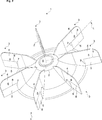
- Figure 2 – is a schematic perspective view of a fan according to an embodiment of the present invention, wherein the fan is at rest and the flexible trailing sections are in the axially straight orientation;
- Figure 3 – is another schematic perspective view of the fan according to an embodiment of the present invention, wherein the fan is rotated in the clockwise direction and the flexible trailing sections are flexed backwards to an axially inclined orientation under the influence of centrifugal forces and the intake air pressure.
- the fan (1) is suitable for cooling a bidirectional induction motor (not shown).
- the bidirectional induction motor comprises a rotating shaft (not shown), a stator (not shown) and a rotor (not shown) which is fixed to the shaft.
- the bidirectional induction motor can be selectively operated so as to rotate the shaft in the clockwise direction or in the anti-clockwise direction about an axial direction (Z) (Fig. 2 and 3).
- the fan (1) comprises a hub (2) which is releasably mountable onto the shaft and one or more than one radially and axially straight blade (3) which is mounted onto the hub (2).
- At least one radially and axially straight blade (3) comprises a stiff leading section (4) and a flexible trailing section (5).
- the flexible trailing section (5) is configured to flex rearwards in the direction opposite to the rotation direction under the influence of the centrifugal forces and the pressure of the intake air during the rotation towards an axially inclined orientation.
- the flexible trailing section (5) is configured to flex about a predetermined axis (L) which has at least a radial component.
- the induction motor of the present invention comprises the fan (1) according to the present invention.
- the hub (2) of the fan (1) is releasably mountable onto the shaft.
- the electrical household appliance (not shown) of the present invention comprises the induction motor according to the present invention.
- At least one radially and axially straight blade (3) has a free end (6) which is disposed off the hub (2).
- the free end (6) extends a predetermined distance in the radial direction away from the hub (2). Such distance can be determined in accordance with the particulars of the induction motor.
- the flexible trailing section (5) defines at least part of the free end (6) that immediately faces the motor. The size and shape of the flexible trailing section (5) may be similarly adjusted in accordance with the particulars of the induction motor, including its geometry, thermal features, power and the like.
- the radially and axially straight blade (3) comprises a cut (7) which partly separates the flexible trailing section (5).
- the length, position and outline of the cut (7) can be similarly adjusted in accordance with the particulars of the induction motor.
- the cut (7) extends parallel to the axial direction (Z).
- the stiff leading section (4) is made from a comparatively stiff material whereas the flexible trailing section (5) is made from a comparatively flexible material.
- the stiff leading section (4) and the flexible trailing section (5) are joined by gluing, welding or any other process known to those skilled in the art.
- the stiff leading section (5) and the flexible trailing section (5) are joined by a flexible joint section (8) which is made from a comparatively flexible material.
- the stiff leading section (5) and the flexible trailing section (5) are made from a comparatively stiff material.
- the flexible trailing section (5) is resiliently biased to an axially straight orientation.
- said predetermined axis (L) extends in the radial direction.
- the hub (2) has a bore (2) which matches the shaft.
- each blade (3) has a stiff leading section (4) and a flexible trailing section (5) (Fig. 2 and 3).
- the number of blades (3) can be adjusted in accordance with the specific application for which the induction motor is designed.
- the induction motor comprises a housing (not shown) which totally encloses the stator and the rotor.
- the hub (2) of the fan (1) is releasably mountable onto the rear end of the shaft which protrudes out of the housing.
- the induction motor is provided as a totally-enclosed fan-cooled type induction motor.
- the totally-enclosed fan-cooled type induction motor comprises a protective cover (not shown) which accommodates the fan (1).
- the protective cover has an attachment means (not shown) for detachably attaching the protective cover onto the housing and ventilation openings (not shown) which face the air intake side of the fan (1).
Landscapes
- Engineering & Computer Science (AREA)
- Mechanical Engineering (AREA)
- General Engineering & Computer Science (AREA)
- Power Engineering (AREA)
- Motor Or Generator Cooling System (AREA)
- Structures Of Non-Positive Displacement Pumps (AREA)
Abstract
The present invention relates to a fan (1) for cooling a bidirectional induction motor. The fan (1) comprises a hub (2) which is releasably mountable onto the shaft of the induction motor and one or more than one radially and axially straight blade (3) which is mounted onto the hub (2). In the fan (1 ) of the present invention at least one radially and axially straight blade (3) comprises a stiff leading section (4) and a flexible trailing section (5). The flexible trailing section (5) flexes rearwards in response to the rotation towards an axially inclined orientation about a predetermined axis (L) which has a radial component.
Description
The present invention relates to a fan for cooling an induction motor, in particular, a totally-enclosed fan-cooled bidirectional induction motor.
Induction motors are commonly known. Induction motors can be used both in industrial and domestic applications. For instance, an induction motor can be used to drive the rotating member of a household appliance. An induction motor generally comprises a rotating shaft, a stator and a squirrel cage rotor which is fixed to the shaft. The induction motor is usually provided with a housing which comprises a cylindrical main body with fins and two covers which totally enclose the stator and the rotor so as to protect it from moisture and dirt. The forward end of the shaft is protruded out of the bearing in the front cover and can be coupled, for instance, with the aforementioned rotating member. During the operation of the induction motor a large amount of heat is generated. Therefore, the induction motor must be suffiently cooled. In general, the totally-enclosed induction motor is provided with an external cooling facility which includes a fan and a fan guard that cool the induction motor from the outside by way of conveying the ambient air over its housing. The rear end of the shaft is usually protruded out of the bearing in the rear cover and is directly coupled with the hub of the external fan. Thus, the external fan rotates together with the shaft. A totally-enclosed fan-cooled induction motor can be generally operated so as to rotate the shaft in the clockwise direction or in the anti-clockwise direction about the axial direction. The direction of rotation is usually decided in accordance with the specific type of application in which the induction motor is to be used. In some applications, it might be desirable to selectively operate the induction motor in either one of the clockwise direction and the anti-clockwise direction. In either of the above applications, the induction motor must be sufficiently cooled. Therefore, the fan is generally provided with a plurality of radially and axially straight blades in order to safeguard a uniform cooling of the induction motor regardless of the direction of rotation. Fig. 1 shows a prior art fan (1´) which can be used for cooling a bidirectional induction motor. The fan (1´) comprises a hub (2´) which is releasably mountable onto the shaft of the induction motor and a plurality of radially and axially straight blades (3´) which are mounted onto the hub (2´).
In general, the cooling performance of the fan (1´) is of utmost importance in view of the thermal protection of the induction motor and its performance.
An objective of the present invention is to provide a fan for use in the cooling facility of a bidirectional induction motor and an electrical household appliance having the same which overcomes the drawbacks of the prior art in a cost effective way and which enables an improved cooling performance.
This objective has been achieved by the fan as defined in claim 1, the induction motor as defined in claim 8 and the electrical household appliance as defined in claim 11. Further achievements have been attained by the subject-matters respectively defined in the dependent claims.
In the fan of the present invention, at least one radially and axially straight blade comprises a stiff leading section and a flexible trailing section. The flexible trailing section flexes, under the influence of centrifugal forces during the rotation, rearwards to an axially inclined orientation about a predetermined axis that has a radial component.
With the present invention, particularly by virtue of the flexible trailing sections, the fan blades dynamically incline backwards, namely in the direction opposite to the rotation direction, in response to the rotation and under the influence of the pressure exerted by the impinging intake air. Thereby, the fan assumes the shape of an axial fan and thus, the flexible trailing sections of the blades sweep with their inclined surfaces the intake air along the axial direction towards the induction motor. Thereby, regardless of the rotation direction, the amount of air which flows towards the induction motor comparatively increases and the cooling performance improves. The fan of the present invention is not limited for use with a totally-enclosed induction motor, but can also be used for cooling an open induction motor. The specific electrical connection to be made for operating the induction motor in either of the clockwise direction or the anti-clockwise direction can be decided in accordance with the type of application, or the type of appliance in which the motor is to be used. Alternatively, the induction motor can be selectively operated in either one of the rotation directions. With the fan of present invention, the induction motor can be cooled with an improved performance regardless of the rotation direction.
In an embodiment, the leading section is made from a comparatively stiff material.
The trailing section is made from a comparatively flexible material which allows a sufficient flexure in the direction opposite to the rotation direction during the rotation. Alternatively, the trailing section can be made from the same material as the stiff leading section, but with a comparatively reduced thickness so as to allow a sufficient flexure. Alternatively, the trailing section can be made, as before, from the same material as the stiff leading section and joined to the leading section through a flexible interface. Thereby, the trailing section can flex backwards. The flexible interface is made from a comparatively flexible material. Alternatively, said flexible interface can be made from the same material as the stiff leading section, but with a comparatively reduced thickness so as to allow a sufficient flexure. The fan, including the leading sections, the trailing sections and the respective interfaces therebetween can be integrally molded. Alternatively, the sections and the respective interface can be mutually joined by a gluing process, a welding process or any other process known to those skilled in the art. Alternatively, the interface between the leading section and the trailing section can be provided with a joint, in particular two mutually separate and co-operating hinges. The joint can be integrally formed with the leading section and the trailing section respectively. Alternatively the hinges can be subsequently mounted to the leading section and the trailing section. In the foregoing alternative versions of this embodiment, the fan can be manufactured, for instance, from plastic and/or metal material.
In another embodiment, the flexible trailing section is provided as part of the free end of the blade that extends off the hub and immediately faces the motor. This specific location of the flexible trailing section improves the axial flow of the intake air towards the induction motor.
In another embodiment, the flexible trailing section is partly separated from the blade through a cut formed therein. The cut allows the trailing section to flex more easily.
In another embodiment, the flexible trailing section is resiliently biased to an axially straight orientation. When the induction motor is stopped, the flexible trailing section returns from the axially inclined ordination to the axially straight orientation.
In another embodiment, flexible trailing section flexes about a radial axis. Alternatively, such flexing axis may also have an axial component.
The present invention also provides an induction motor which has the fan of the present invention.
In another embodiment, the induction motor is provided as a totally-enclosed fan-cooled type induction motor which has a housing that totally encloses the stator and the rotor. Alternatively, the induction motor can be provided as an open type induction motor.
In another embodiment, the totally-enclosed fan-cooled type induction motor also includes a protective cover which protects the fan from spreading material.
The present invention also provides an electrical household appliance which has the induction motor of the present invention.
Additional advantages of the fan, the induction motor and the household appliance of the present invention will become more apparent with the detailed description of the embodiments with reference to the accompanying drawings in which:
Figure 1 – is a schematic perspective view of a fan according to the prior art;
Figure 2 – is a schematic perspective view of a fan according to an embodiment of the present invention, wherein the fan is at rest and the flexible trailing sections are in the axially straight orientation;
Figure 3 – is another schematic perspective view of the fan according to an embodiment of the present invention, wherein the fan is rotated in the clockwise direction and the flexible trailing sections are flexed backwards to an axially inclined orientation under the influence of centrifugal forces and the intake air pressure.
The reference signs appearing on the drawings relate to the following technical features.
- Fan
- Hub
- Blade
- Leading section
- Trailing section
- Free end
- Cut
- Joint section
- Bore
The fan (1) is suitable for cooling a bidirectional induction motor (not shown).
The bidirectional induction motor comprises a rotating shaft (not shown), a stator (not shown) and a rotor (not shown) which is fixed to the shaft. The bidirectional induction motor can be selectively operated so as to rotate the shaft in the clockwise direction or in the anti-clockwise direction about an axial direction (Z) (Fig. 2 and 3).
The fan (1) comprises a hub (2) which is releasably mountable onto the shaft and one or more than one radially and axially straight blade (3) which is mounted onto the hub (2).
In the fan (1) of the present invention, at least one radially and axially straight blade (3) comprises a stiff leading section (4) and a flexible trailing section (5). The flexible trailing section (5) is configured to flex rearwards in the direction opposite to the rotation direction under the influence of the centrifugal forces and the pressure of the intake air during the rotation towards an axially inclined orientation. The flexible trailing section (5) is configured to flex about a predetermined axis (L) which has at least a radial component.
The induction motor of the present invention comprises the fan (1) according to the present invention. The hub (2) of the fan (1) is releasably mountable onto the shaft.
The electrical household appliance (not shown) of the present invention comprises the induction motor according to the present invention.
In an embodiment, at least one radially and axially straight blade (3) has a free end (6) which is disposed off the hub (2). The free end (6) extends a predetermined distance in the radial direction away from the hub (2). Such distance can be determined in accordance with the particulars of the induction motor. The flexible trailing section (5) defines at least part of the free end (6) that immediately faces the motor. The size and shape of the flexible trailing section (5) may be similarly adjusted in accordance with the particulars of the induction motor, including its geometry, thermal features, power and the like.
In another embodiment, the radially and axially straight blade (3) comprises a cut (7) which partly separates the flexible trailing section (5). The length, position and outline of the cut (7) can be similarly adjusted in accordance with the particulars of the induction motor. In a version of this embodiment, the cut (7) extends parallel to the axial direction (Z).
In another embodiment, the stiff leading section (4) is made from a comparatively stiff material whereas the flexible trailing section (5) is made from a comparatively flexible material. The stiff leading section (4) and the flexible trailing section (5) are joined by gluing, welding or any other process known to those skilled in the art.
In an alternative embodiment, the stiff leading section (5) and the flexible trailing section (5) are joined by a flexible joint section (8) which is made from a comparatively flexible material. In this embodiment, the stiff leading section (5) and the flexible trailing section (5) are made from a comparatively stiff material.
In another embodiment, the flexible trailing section (5) is resiliently biased to an axially straight orientation.
In another embodiment, said predetermined axis (L) extends in the radial direction.
In another embodiment, the hub (2) has a bore (2) which matches the shaft.
In another embodiment, each blade (3) has a stiff leading section (4) and a flexible trailing section (5) (Fig. 2 and 3). The number of blades (3) can be adjusted in accordance with the specific application for which the induction motor is designed.
In another embodiment, the induction motor comprises a housing (not shown) which totally encloses the stator and the rotor. The hub (2) of the fan (1) is releasably mountable onto the rear end of the shaft which protrudes out of the housing. In this embodiment, the induction motor is provided as a totally-enclosed fan-cooled type induction motor.
In another embodiment, the totally-enclosed fan-cooled type induction motor comprises a protective cover (not shown) which accommodates the fan (1). The protective cover has an attachment means (not shown) for detachably attaching the protective cover onto the housing and ventilation openings (not shown) which face the air intake side of the fan (1).
Claims (11)
- A fan (1) for cooling a bidirectional induction motor comprising a shaft, wherein the induction motor is selectively operable so as to rotate the shaft in the clockwise direction or in the anti-clockwise direction about an axial direction (Z), the fan (1) comprising a hub (2) which is releasably mountable onto the shaft and one or more than one radially and axially straight blade (3) which is mounted onto the hub (2), characterized in thatat least one radially and axially straight blade (3) comprising a stiff leading section (4) and a flexible trailing section (5), wherein the flexible trailing section (5) is configured to flex rearwards under the influence of centrifugal forces during the rotation to an axially inclined orientation about a predetermined axis (L) which has a radial component.
- The fan (1) according to claim 1, characterized in that at least one radially and axially straight blade (3) has a free end (6) which is disposed off the hub (2), wherein the flexible trailing section (5) defines at least part of the free end (6) that immediately faces the motor.
- The fan (1) according to claim 1 or 2, characterized in that at least one radially and axially straight blade (3) comprising a cut (7) which separates a part of the flexible trailing section (5).
- The fan (1) according to any one of claims 1 to 4, characterized in that the stiff leading section (4) and the flexible trailing section (5) are respectively made from a comparatively stiff material and a comparatively flexible material which are joined with each other.
- The fan (1) according to any one of claims 1 to 4, characterized in that at least one radially and axially straight blade (3) comprising a joint section (8) which is disposed between the stiff leading section (4) and the flexible trailing section (5), wherein the stiff leading section (5) and the flexible trailing section (5) are made both from a comparatively stiff material and the joint section (8) is made from a comparatively flexible material.
- The fan (1) according to claim 1 to 5, characterized in that the flexible trailing section (5) is biased to an axially straight orientation.
- The fan (1) according to claim 1 to 6, characterized in that said predetermined axis (L) extends in the radial direction.
- An induction motor comprising a rotating shaft, a stator and a rotor which is fixed to the shaft, wherein the induction motor can be operated so as to rotate the shaft in the clockwise direction or in the anti-clockwise direction about an axial direction (Z), characterized in that the fan (1) as defined in any one of claims 1 to 7, wherein the hub (2) is releasably mounted onto the shaft.
- The induction motor according to claim 8, characterized in that a housing which totally encloses the stator and the rotor, wherein the hub (2) of the fan (1) is releasably mounted onto the rear end of the shaft which protrudes out of the housing.
- The induction motor according to claim 9, characterized in that a protective cover which accommodates the fan (1), wherein the protective cover has an attachment means for detachably attaching the protective cover onto the housing and ventilation openings which face the air intake side of the fan (1).
- An electrical household appliance characterized in that the induction motor as defined in any one of claims 8 to 10.
Priority Applications (1)
| Application Number | Priority Date | Filing Date | Title |
|---|---|---|---|
| PCT/EP2014/078742 WO2016096041A1 (en) | 2014-12-19 | 2014-12-19 | Fan for cooling an induction motor |
Applications Claiming Priority (1)
| Application Number | Priority Date | Filing Date | Title |
|---|---|---|---|
| PCT/EP2014/078742 WO2016096041A1 (en) | 2014-12-19 | 2014-12-19 | Fan for cooling an induction motor |
Publications (1)
| Publication Number | Publication Date |
|---|---|
| WO2016096041A1 true WO2016096041A1 (en) | 2016-06-23 |
Family
ID=52134207
Family Applications (1)
| Application Number | Title | Priority Date | Filing Date |
|---|---|---|---|
| PCT/EP2014/078742 Ceased WO2016096041A1 (en) | 2014-12-19 | 2014-12-19 | Fan for cooling an induction motor |
Country Status (1)
| Country | Link |
|---|---|
| WO (1) | WO2016096041A1 (en) |
Cited By (2)
| Publication number | Priority date | Publication date | Assignee | Title |
|---|---|---|---|---|
| EP3957864A1 (en) * | 2020-08-17 | 2022-02-23 | Siemens Aktiengesellschaft | Fan and dynamoelectric machine with a fan |
| EP4617503A1 (en) * | 2024-03-11 | 2025-09-17 | Carrier Corporation | Impeller with variable backsweep angle |
Citations (3)
| Publication number | Priority date | Publication date | Assignee | Title |
|---|---|---|---|---|
| JPH0888955A (en) * | 1994-09-13 | 1996-04-02 | Toyo Electric Mfg Co Ltd | Electric motor cooling fan |
| JP2000050574A (en) * | 1998-07-24 | 2000-02-18 | Matsushita Electric Ind Co Ltd | Fully enclosed fan-type induction motor |
| DE102008025700A1 (en) * | 2008-05-29 | 2009-12-03 | Siemens Aktiengesellschaft | Radial fan i.e. disk fan, for e.g. self ventilation of e.g. compressor, has fan disk with radially running blades arranged on fan disk, where part of blades comprises flexible material e.g. polypropylene |
-
2014
- 2014-12-19 WO PCT/EP2014/078742 patent/WO2016096041A1/en not_active Ceased
Patent Citations (3)
| Publication number | Priority date | Publication date | Assignee | Title |
|---|---|---|---|---|
| JPH0888955A (en) * | 1994-09-13 | 1996-04-02 | Toyo Electric Mfg Co Ltd | Electric motor cooling fan |
| JP2000050574A (en) * | 1998-07-24 | 2000-02-18 | Matsushita Electric Ind Co Ltd | Fully enclosed fan-type induction motor |
| DE102008025700A1 (en) * | 2008-05-29 | 2009-12-03 | Siemens Aktiengesellschaft | Radial fan i.e. disk fan, for e.g. self ventilation of e.g. compressor, has fan disk with radially running blades arranged on fan disk, where part of blades comprises flexible material e.g. polypropylene |
Cited By (3)
| Publication number | Priority date | Publication date | Assignee | Title |
|---|---|---|---|---|
| EP3957864A1 (en) * | 2020-08-17 | 2022-02-23 | Siemens Aktiengesellschaft | Fan and dynamoelectric machine with a fan |
| EP4617503A1 (en) * | 2024-03-11 | 2025-09-17 | Carrier Corporation | Impeller with variable backsweep angle |
| US12492707B2 (en) | 2024-03-11 | 2025-12-09 | Carrier Corporation | Impeller with variable backsweep angle |
Similar Documents
| Publication | Publication Date | Title |
|---|---|---|
| JP6851446B2 (en) | Electric motor | |
| US10064470B2 (en) | Motor and a hair care appliance comprising a motor | |
| EP1015764B1 (en) | Axial fan with self-cooled motor | |
| EP0761979B1 (en) | Axial flow fan | |
| KR101256428B1 (en) | Cooling fan | |
| CN107110171B (en) | Electric blower and electric vacuum cleaner equipped with it | |
| CN109276183B (en) | Air supply device and dust collector | |
| JP2012510245A5 (en) | ||
| WO2016096041A1 (en) | Fan for cooling an induction motor | |
| US6494681B2 (en) | Combined axial flow and centrifugal fan in an electrical motor | |
| US9790947B2 (en) | Fan assembly | |
| JP6581361B2 (en) | Electric blower and vacuum cleaner equipped with the same | |
| CN216617980U (en) | A fan and cleaner | |
| CN104619993A (en) | Ventilation system | |
| CN113014052B (en) | Fan driving assembly | |
| KR102036319B1 (en) | Servomotor having case cooling function | |
| JP2010042467A5 (en) | ||
| US7372180B2 (en) | Electric motor with an air duct | |
| JP2016156365A (en) | Centrifugal fan | |
| JP7081910B2 (en) | Electric blower and vacuum cleaner equipped with it | |
| CN108649733B (en) | Motor with a motor housing | |
| JP5352360B2 (en) | Electric blower and electric vacuum cleaner provided with the same | |
| JP2018007415A (en) | Cooling fan and motor | |
| JP5724380B2 (en) | Axial fan | |
| JP6421610B2 (en) | Blower |
Legal Events
| Date | Code | Title | Description |
|---|---|---|---|
| 121 | Ep: the epo has been informed by wipo that ep was designated in this application |
Ref document number: 14815746 Country of ref document: EP Kind code of ref document: A1 |
|
| NENP | Non-entry into the national phase |
Ref country code: DE |
|
| 122 | Ep: pct application non-entry in european phase |
Ref document number: 14815746 Country of ref document: EP Kind code of ref document: A1 |