WO2016093324A1 - ミューオン-プラズモイド複合核融合炉 - Google Patents
ミューオン-プラズモイド複合核融合炉 Download PDFInfo
- Publication number
- WO2016093324A1 WO2016093324A1 PCT/JP2015/084706 JP2015084706W WO2016093324A1 WO 2016093324 A1 WO2016093324 A1 WO 2016093324A1 JP 2015084706 W JP2015084706 W JP 2015084706W WO 2016093324 A1 WO2016093324 A1 WO 2016093324A1
- Authority
- WO
- WIPO (PCT)
- Prior art keywords
- plasmoid
- muon
- fusion reactor
- solid
- solid hydrogen
- Prior art date
- Legal status (The legal status is an assumption and is not a legal conclusion. Google has not performed a legal analysis and makes no representation as to the accuracy of the status listed.)
- Ceased
Links
Images

Classifications
-
- G—PHYSICS
- G21—NUCLEAR PHYSICS; NUCLEAR ENGINEERING
- G21B—FUSION REACTORS
- G21B1/00—Thermonuclear fusion reactors
-
- G—PHYSICS
- G21—NUCLEAR PHYSICS; NUCLEAR ENGINEERING
- G21B—FUSION REACTORS
- G21B3/00—Low temperature nuclear fusion reactors, e.g. alleged cold fusion reactors
-
- Y—GENERAL TAGGING OF NEW TECHNOLOGICAL DEVELOPMENTS; GENERAL TAGGING OF CROSS-SECTIONAL TECHNOLOGIES SPANNING OVER SEVERAL SECTIONS OF THE IPC; TECHNICAL SUBJECTS COVERED BY FORMER USPC CROSS-REFERENCE ART COLLECTIONS [XRACs] AND DIGESTS
- Y02—TECHNOLOGIES OR APPLICATIONS FOR MITIGATION OR ADAPTATION AGAINST CLIMATE CHANGE
- Y02E—REDUCTION OF GREENHOUSE GAS [GHG] EMISSIONS, RELATED TO ENERGY GENERATION, TRANSMISSION OR DISTRIBUTION
- Y02E30/00—Energy generation of nuclear origin
- Y02E30/10—Nuclear fusion reactors
Definitions
- the present invention relates to a nuclear fusion reactor, and more particularly to a nuclear fusion reactor with improved reaction efficiency.
- Non-Patent Document 1 There are mainly three types of existing nuclear fusion reactors, and the first is a high-temperature plasma magnetic confinement method, such as a tokamak method and a stellar method (for example, Patent Document 1). The second is an inertial confinement method in which a target is implosioned with a laser beam or the like to react in a high temperature and high density state in a short time. The third is a muon catalyst system using muons (for example, Non-Patent Document 1).
- a high-temperature plasma magnetic confinement method such as a tokamak method and a stellar method
- Patent Document 1 The second is an inertial confinement method in which a target is implosioned with a laser beam or the like to react in a high temperature and high density state in a short time.
- the third is a muon catalyst system using muons (for example, Non-Patent Document 1).
- Muon-catalyzed fusion reactors targeting ice pellets of hydrogen and deuterium are known to be able to stably obtain fusion reactions as research is progressing in the fields of nuclear physics and accelerator science.
- the magnetic confinement method has many problems in realizing a practical furnace such as disruption due to instability and furnace wall material.
- the inertial containment method has many problems in the development of laser light, the energy recovery method, and the like.
- the muon catalyst method is known to be able to stably obtain a fusion reaction, but the energy production efficiency needs to be further improved by a factor of 10 or more, and it is difficult to solve with only the muon production efficiency. Met.
- the present invention seeks to provide a muon-plasmoid compound fusion reactor capable of reactivating muons to increase energy production efficiency.
- a muon-plasmoid composite fusion reactor is connected to a target container for causing a fusion reaction, and to the target container, and solid hydrogen is incident on the target container.
- a solid hydrogen ice mist generation source for forming a solid hydrogen ice mist and a target vessel are connected to generate a magnetized plasmoid and transfer the magnetized plasmoid into the solid hydrogen ice mist in the target vessel to form a solid-plasma composite region
- a muon source connected to the target vessel and for injecting a muon into the solid-plasma composite region to obtain a nuclear reaction.
- the solid hydrogen ice mist generation source and the plasmoid generation source may be controlled so that the generated solid-plasma composite region is maintained for a longer time than the muon lifetime.
- the plasmoid generation source may be any one that transfers the magnetized plasmoid faster than the plasma diffusion or relaxation time scale into the solid hydrogen ice mist in the target container.
- the muon generation source may be any source that enters the muon while the solid hydrogen ice mist sublimes.
- an energy converter connected to the target container and for recovering the fusion product may be provided.
- the plasmoid generation source may be one that induces the fusion product to the energy converter using a magnetic field confining the generated magnetized plasmoid as a guide magnetic field.
- the muon-plasmoid compound fusion reactor of the present invention has an advantage that muon can be reactivated and energy production efficiency is increased.
- FIG. 1 is a schematic diagram for explaining a muon reaction cycle.
- FIG. 2 is a schematic cross-sectional side view for explaining the muon-plasmoid compound fusion reactor of the present invention.
- FIG. 1 is a schematic diagram for explaining the muon reaction cycle.
- the muon reaction cycle how many times a muon reacts as a catalyst determines the energy production efficiency. That is, the greatest factor governing the energy production efficiency is the rate at which muons acting as catalysts combine with ⁇ particles produced by fusion to become ⁇ and froze from the reaction cycle, that is, ⁇ -adhesion rate.
- This ⁇ is known to be ionized in a plasma of about several tens of eV, and acts again as a catalyst when it re-enters solid hydrogen. Therefore, in the present invention, it was considered to create a situation in which “surgical” plasma is surrounded by solid hydrogen, and to enter a muon as a target.
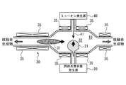
- FIG. 2 is a schematic cross-sectional side view for explaining the muon-plasmoid compound fusion reactor of the present invention.
- the muon-plasmoid compound fusion reactor of the present invention mainly includes a target vessel 10, a solid hydrogen ice fog generation source 20, a plasmoid generation source 30, and a muon generation source 40.
- the target container 10 is a container for causing a fusion reaction.
- it is a vacuum vessel, and the inside is kept in a vacuum by a vacuum exhaust equipment or the like. Further, since the nuclear fusion reaction involves generation of radiation, a shielding material capable of shielding radiation is used.
- the target container 10 can be a target used in a fusion reactor or to be developed in the future, and is not limited to a specific object.
- the solid hydrogen ice mist generation source 20 is connected to the target container 10. Then, solid hydrogen enters the target container 10 to form a solid hydrogen ice mist 21.
- the solid hydrogen ice mist 21 is formed in a cloud shape by injecting solid hydrogen into a mist.
- the solid hydrogen ice mist generation source 20 for example, one that can cool hydrogen into a fine pellet and inject it into the target container 10 may be used.
- the solid hydrogen ice mist generation source 20 it is possible to use an existing one or one to be developed in the future.
- the plasmoid generation source 30 is connected to the target container 10. Then, the magnetized plasmoid 31 is generated and transferred into the solid hydrogen ice mist 21 in the target container 10 to form a solid-plasma composite region 32. That is, when the magnetized plasmoid 31 is moved toward the solid hydrogen ice mist 21 at a high speed, a solid-plasma composite region 32 is formed, which is a region surrounded by the “slack” magnetized plasmoid 31 around the solid hydrogen ice mist 21. Specifically, the plasmoid generation source 30 transfers the magnetized plasmoid 31 into the solid hydrogen ice mist 21 in the target container 10 faster than the time scale of plasma diffusion or relaxation.
- the solid-plasma composite region 32 is formed by controlling the surrounding of the solid hydrogen ice mist 21 with the magnetized plasmoid 31 before the plasma disappears.
- the generated solid-plasma composite region 32 is controlled by the solid hydrogen ice mist generation source 20 and the plasmoid generation source 30 so as to be maintained for a longer time than the muon lifetime.
- the lifetime of the muon is about 2 ⁇ sec
- the solid-plasma composite region 32 is controlled to be maintained for a significantly longer time, for example, about several tens of ⁇ sec.
- a reactivation region having a relatively high temperature (for example, several tens of eV) such as 31 can be obtained simultaneously.
- the plasmoid generation source 30 for example, an existing one or a device to be developed in the future such as a field-reversed configuration (FRC) plasma generator can be used.
- FRC field-reversed configuration
- the magnetized plasmoid generated by the reverse magnetic field theta pinch type FRC device may be transferred to the confining portion at high speed toward the solid hydrogen ice mist 21 by the external magnetic field gradient created by the magnetic field coil (quasi-stationary magnetic field coil) 35.
- the muon generation source 40 is connected to the target container 10.
- the muon generation source 40 makes the muon 41 incident on the solid-plasma composite region 32. Specifically, the muon generation source 40 enters the muon 41 while the solid hydrogen ice mist 21 sublimes. Thereby, a nuclear reaction is obtained in the target container 10. Then, the muon 41 that has acted as a catalyst is combined with the ⁇ particles generated by fusion and becomes ⁇ . This ⁇ is ionized in the solid-plasma composite region 32, and the muon again acts as a catalyst. Therefore, the reaction efficiency of muons is increased and the energy production efficiency is increased.
- the muon generation source 40 it is possible to use an existing one or a thing to be developed in the future, such as a phase space rotation type or an ionization cooling type.
- the muon-plasmonoid can reactivate the muon and the region in which the muon acts as a catalyst many times is generated. This increases energy production efficiency.
- the muon-plasmoid compound fusion reactor of the present invention is convenient for energy recovery. That is, the fusion reaction product can be transferred by using a magnetic field confining plasma as a guide magnetic field.
- an energy converter for recovering the fusion product can be connected to the target vessel 10.
- a magnetic field confining the generated magnetized plasmoid is used as a guide magnetic field to induce the fusion product to the energy converter.
- the muon-plasmoid compound fusion reactor of the present invention can directly induce the fusion product to the energy converter, and is highly adaptable as an energy recovery system.
- muon-plasmoid compound fusion reactor of the present invention is not limited to the above illustrated example, and it is needless to say that various modifications can be made without departing from the scope of the present invention.
Landscapes
- Physics & Mathematics (AREA)
- Engineering & Computer Science (AREA)
- Plasma & Fusion (AREA)
- General Engineering & Computer Science (AREA)
- High Energy & Nuclear Physics (AREA)
- Physical Or Chemical Processes And Apparatus (AREA)
- Catalysts (AREA)
Abstract
エネルギ生産効率を高めるためにミューオンの再活性化を行うことが可能なミューオン-プラズモイド複合核融合炉を提供する。 核融合反応を得るためのミューオン-プラズモイド複合核融合炉は、標的容器10と固体水素氷霧発生源20とプラズモイド発生源30とミューオン発生源40とからなる。固体水素氷霧発生源20は、標的容器10に接続され、標的容器10内に固体水素を入射し固体水素氷霧21を形成する。プラズモイド発生源30は、標的容器10に接続され、磁化プラズモイド31を発生すると共に標的容器10内の固体水素氷霧21中に磁化プラズモイドを移送し、固体-プラズマ複合領域32を形成する。ミューオン発生源40は、標的容器10に接続され、固体-プラズマ複合領域32にミューオン41を入射し核反応を得る。
Description
本発明は核融合炉に関し、特に、反応効率を高めた核融合炉に関する。
現存する核融合炉の方式は主に3種類あり、1つ目は高温プラズマの磁気閉じ込め方式でありトカマク方式、ステラレータ方式等である(例えば特許文献1)。2つ目はレーザ光等でターゲットを爆縮し高温高密度状態で短時間に反応を起こす慣性閉じ込め方式である。さらに3つ目はミューオンを用いたミューオン触媒方式である(例えば非特許文献1)。
水素や重水素のアイスペレットをターゲットとしたミューオン触媒核融合炉は、核物理や加速器科学の分野で研究が進められ、安定的に核融合反応を得られることが知られている。
N.Nakamura et al.「Measurements of 3He accumulation effect on muon catalyzed fusion in the solid/liquid DT mixtures」Physics Letters B, Volume 465, Issues 1-4, 21 October 1999, Pages 74-80
磁気閉じ込め方式は、不安定性に伴うディスラプションや炉壁材料等、実用炉の実現には多くの課題がある。また、慣性封じ込め方式は、レーザ光の開発やエネルギ回収方法等において課題も多い。そして、ミューオン触媒方式は、安定的に核融合反応を得られることが知られているが、エネルギ生産効率としては10倍以上のさらなる向上が必要であり、ミューオン生成効率のみで解決するのは困難であった。
本発明は、斯かる実情に鑑み、エネルギ生産効率を高めるためにミューオンの再活性化を行うことが可能なミューオン-プラズモイド複合核融合炉を提供しようとするものである。
上述した本発明の目的を達成するために、本発明によるミューオン-プラズモイド複合核融合炉は、核融合反応を起こすための標的容器と、標的容器に接続され、標的容器内に固体水素を入射し固体水素氷霧を形成するための固体水素氷霧発生源と、標的容器に接続され、磁化プラズモイドを発生すると共に標的容器内の固体水素氷霧中に磁化プラズモイドを移送し、固体-プラズマ複合領域を形成するためのプラズモイド発生源と、標的容器に接続され、固体-プラズマ複合領域にミューオンを入射し核反応を得るためのミューオン発生源と、を具備するものである。
ここで、固体水素氷霧発生源及びプラズモイド発生源は、生成される固体-プラズマ複合領域がミューオンの寿命に比べて長い時間維持されるように制御されるものであれば良い。
また、プラズモイド発生源は、磁化プラズモイドをプラズマの拡散又は緩和の時間スケールより速く、標的容器内の固体水素氷霧中に移送するものであれば良い。
また、ミューオン発生源は、固体水素氷霧が昇華する間にミューオンを入射するものであれば良い。
さらに、標的容器に接続され、核融合生成物を回収するためのエネルギ変換器を具備するものであっても良い。
また、プラズモイド発生源は、発生する磁化プラズモイドを閉じ込める磁場をガイド磁場として用いて核融合生成物をエネルギ変換器に誘導するものであっても良い。
本発明のミューオン-プラズモイド複合核融合炉には、ミューオンの再活性化を行うことが可能でありエネルギ生産効率が高まるという利点がある。
まず、ミューオンの反応サイクルについて説明する。図1に、ミューオンの反応サイクルを説明するための概略模式図を示す。ミューオンの反応サイクルにおいて、1つのミューオンが何回触媒として反応するかがエネルギ生産効率を決定する。即ち、エネルギ生産効率を支配する最大の因子は、触媒として作用したミューオンが、核融合生成されたα粒子と結合してαμとなり、反応サイクルから遁走する割合、即ち、α-付着率である。このαμは、数十eV程度のプラズマ中で電離することが知られており、これが固体水素中に再入射することで再度触媒として作用する。そこで、本発明では、固体水素の周囲を「ぬるい」プラズマが取り巻く状況を作り、これを標的としてミューオンを入射することを考えた。
以下、本発明を実施するための形態を図示例と共に説明する。図2は、本発明のミューオン-プラズモイド複合核融合炉を説明するための概略側断面図である。図示の通り、本発明のミューオン-プラズモイド複合核融合炉は、標的容器10と、固体水素氷霧発生源20と、プラズモイド発生源30と、ミューオン発生源40とから主に構成されている。
標的容器10は、核融合反応を起こすための容器である。例えば真空容器であり、真空排気設備等により内部が真空に保たれるものである。また、核融合反応では放射線の発生を伴うため、放射線の遮蔽が可能な遮蔽材が用いられる。標的容器10は、核融合炉でこれまで用いられているものや今後開発されるべきものを用いることが可能であり、特定の物には限定されない。
固体水素氷霧発生源20は、標的容器10に接続されるものである。そして、標的容器10内に固体水素を入射し固体水素氷霧21を形成するものである。固体水素氷霧21は、固体水素を霧状に噴射することで、雲状に形成されたものである。固体水素氷霧発生源20としては、例えば細かいペレット状に水素を冷却し、これを標的容器10内に注入することが可能なものを用いれば良い。固体水素氷霧発生源20としても、既存のものや今後開発されるべきものを用いることが可能である。
プラズモイド発生源30は、標的容器10に接続されるものである。そして、磁化プラズモイド31を発生すると共に、標的容器10内の固体水素氷霧21中に移送し、固体-プラズマ複合領域32を形成するものである。即ち、磁化プラズモイド31を固体水素氷霧21に向けて高速に移動させると、固体水素氷霧21の周囲が「ぬるい」磁化プラズモイド31で取り巻かれる領域である固体-プラズマ複合領域32が形成される。具体的には、プラズモイド発生源30は、磁化プラズモイド31を、プラズマの拡散又は緩和の時間スケールより速く、標的容器10内の固体水素氷霧21中に移送する。これにより、プラズマが消える前に固体水素氷霧21の周囲を磁化プラズモイド31で取り巻くように制御して固体-プラズマ複合領域32が形成される。また、生成される固体-プラズマ複合領域32は、ミューオンの寿命に比べて長い時間維持されるように、固体水素氷霧発生源20及びプラズモイド発生源30により制御される。具体的には、ミューオンの寿命は約2μ秒であるため、これより有意に長い時間、例えば、数十μ秒程度、固体-プラズマ複合領域32が維持されるように制御する。
このように、固体水素氷霧発生源20及びプラズモイド発生源30を用いることで、固体水素氷霧21のような高密度で低温(例えば電子温度が2eV未満)の触媒反応領域と、それを取り巻く磁化プラズモイド31のような比較的高温(例えば数十eV)の再活性化領域を同時に得られるようにする。
プラズモイド発生源30としては、例えば磁場反転配位(FRC:Field-Reversed Configuration)プラズマ発生装置等、既存のものや今後開発されるべきものを用いることが可能である。例えば、逆磁場シータピンチ型FRC装置により生成された磁化プラズモイドを、磁場コイル(準定常磁場コイル)35が作る外部磁場勾配により固体水素氷霧21に向けて高速に閉じ込め部に移送すれば良い。
そして、ミューオン発生源40は、標的容器10に接続されるものである。ミューオン発生源40は、固体-プラズマ複合領域32にミューオン41を入射するものである。具体的には、ミューオン発生源40は、固体水素氷霧21が昇華する間にミューオン41を入射する。これにより、標的容器10内で核反応が得られる。そして、触媒として作用したミューオン41が、核融合生成されたα粒子と結合しαμとなるが、このαμが固体-プラズマ複合領域32内で電離し、ミューオンが再度触媒として作用する。したがって、ミューオンの反応効率が上がり、エネルギ生産効率が高まることになる。ミューオン発生源40としては、位相空間回転方式のものやイオン化冷却方式のもの等、既存のものや今後開発されるべきものを用いることが可能である。
このように、本発明のミューオン-プラズモイド複合核融合炉によれば、磁化プラズモイドによりミューオンの再活性化が可能となりミューオンが触媒として何度も作用するような領域を生成したことで、反応効率が上がるためエネルギ生産効率が高まる。
さらに、本発明のミューオン-プラズモイド複合核融合炉は、エネルギ回収にも都合が良い。即ち、プラズマを閉じ込める磁場をガイド磁場として用いることで、核融合反応生成物を移送することが可能である。例えば、核融合生成物を回収するためのエネルギ変換器を標的容器10に接続することが可能である。発生した磁化プラズモイドを閉じ込める磁場をガイド磁場として用いて核融合生成物をエネルギ変換器に誘導する。このように、本発明のミューオン-プラズモイド複合核融合炉は、直接エネルギ変換器に核融合生成物を誘導することが可能となり、エネルギ回収システムとしての適合性も高い。
なお、本発明のミューオン-プラズモイド複合核融合炉は、上述の図示例にのみ限定されるものではなく、本発明の要旨を逸脱しない範囲内において種々変更を加え得ることは勿論である。
10 標的容器
20 固体水素氷霧発生源
21 固体水素氷霧
30 プラズモイド発生源
31 磁化プラズモイド
32 固体-プラズマ複合領域
35 磁場コイル
40 ミューオン発生源
41 ミューオン
20 固体水素氷霧発生源
21 固体水素氷霧
30 プラズモイド発生源
31 磁化プラズモイド
32 固体-プラズマ複合領域
35 磁場コイル
40 ミューオン発生源
41 ミューオン
Claims (6)
- 核融合反応を得るためのミューオン-プラズモイド複合核融合炉であって、該ミューオン-プラズモイド複合核融合炉は、
核融合反応を起こすための標的容器と、
前記標的容器に接続され、標的容器内に固体水素を入射し固体水素氷霧を形成するための固体水素氷霧発生源と、
前記標的容器に接続され、磁化プラズモイドを発生すると共に標的容器内の固体水素氷霧中に磁化プラズモイドを移送し、固体-プラズマ複合領域を形成するためのプラズモイド発生源と、
前記標的容器に接続され、固体-プラズマ複合領域にミューオンを入射し核反応を得るためのミューオン発生源と、
を具備することを特徴とするミューオン-プラズモイド複合核融合炉。 - 請求項1に記載のミューオン-プラズモイド複合核融合炉において、前記固体水素氷霧発生源及びプラズモイド発生源は、生成される固体-プラズマ複合領域がミューオンの寿命に比べて長い時間維持されるように制御されることを特徴とするミューオン-プラズモイド複合核融合炉。
- 請求項1又は請求項2に記載のミューオン-プラズモイド複合核融合炉において、前記プラズモイド発生源は、磁化プラズモイドをプラズマの拡散又は緩和の時間スケールより速く、標的容器内の固体水素氷霧中に移送することを特徴とするミューオン-プラズモイド複合核融合炉。
- 請求項1乃至請求項3の何れかに記載のミューオン-プラズモイド複合核融合炉において、前記ミューオン発生源は、固体水素氷霧が昇華する間にミューオンを入射することを特徴とするミューオン-プラズモイド複合核融合炉。
- 請求項1乃至請求項4の何れかに記載のミューオン-プラズモイド複合核融合炉であって、さらに、前記標的容器に接続され、核融合生成物を回収するためのエネルギ変換器を具備することを特徴とするミューオン-プラズモイド複合核融合炉。
- 請求項5に記載のミューオン-プラズモイド複合核融合炉において、前記プラズモイド発生源は、発生する磁化プラズモイドを閉じ込める磁場をガイド磁場として用いて核融合生成物をエネルギ変換器に誘導することを特徴とするミューオン-プラズモイド複合核融合炉。
Applications Claiming Priority (2)
| Application Number | Priority Date | Filing Date | Title |
|---|---|---|---|
| JP2014-250765 | 2014-12-11 | ||
| JP2014250765A JP6429232B2 (ja) | 2014-12-11 | 2014-12-11 | ミューオン−プラズモイド複合核融合炉 |
Publications (1)
| Publication Number | Publication Date |
|---|---|
| WO2016093324A1 true WO2016093324A1 (ja) | 2016-06-16 |
Family
ID=56107501
Family Applications (1)
| Application Number | Title | Priority Date | Filing Date |
|---|---|---|---|
| PCT/JP2015/084706 Ceased WO2016093324A1 (ja) | 2014-12-11 | 2015-12-10 | ミューオン-プラズモイド複合核融合炉 |
Country Status (2)
| Country | Link |
|---|---|
| JP (1) | JP6429232B2 (ja) |
| WO (1) | WO2016093324A1 (ja) |
Cited By (1)
| Publication number | Priority date | Publication date | Assignee | Title |
|---|---|---|---|---|
| WO2018093312A1 (en) * | 2016-11-17 | 2018-05-24 | Ultrafusion Nuclear Power Unp Ab | Apparatus for generating muons with intended use in a fusion reactor |
Families Citing this family (1)
| Publication number | Priority date | Publication date | Assignee | Title |
|---|---|---|---|---|
| RU2758589C1 (ru) * | 2018-02-27 | 2021-11-01 | Тюбу Юниверсити Эдьюкейшнл Фаундейшн | Система ядерного синтеза, способ ядерного синтеза, система обработки долгоживущих продуктов деления для сокращения продолжительности жизни при трансмутации нуклидов и способ обработки долгоживущих продуктов деления для сокращения продолжительности жизни при трансмутации нуклидов |
Citations (3)
| Publication number | Priority date | Publication date | Assignee | Title |
|---|---|---|---|---|
| JP2002148377A (ja) * | 2000-11-09 | 2002-05-22 | Japan Atom Energy Res Inst | 重水素氷の連続生成・装填方法 |
| JP2009096441A (ja) * | 2007-10-15 | 2009-05-07 | Motohiko Inai | ミューオン触媒核融合炉を動力源とした飛翔体 |
| WO2013074666A2 (en) * | 2011-11-14 | 2013-05-23 | The Regents Of The University Of California | Systems and methods for forming and maintaining a high performance frc |
Family Cites Families (1)
| Publication number | Priority date | Publication date | Assignee | Title |
|---|---|---|---|---|
| JP3145555B2 (ja) * | 1994-02-28 | 2001-03-12 | 核燃料サイクル開発機構 | 核融合を利用した放射性廃棄物の消滅処理方法 |
-
2014
- 2014-12-11 JP JP2014250765A patent/JP6429232B2/ja not_active Expired - Fee Related
-
2015
- 2015-12-10 WO PCT/JP2015/084706 patent/WO2016093324A1/ja not_active Ceased
Patent Citations (3)
| Publication number | Priority date | Publication date | Assignee | Title |
|---|---|---|---|---|
| JP2002148377A (ja) * | 2000-11-09 | 2002-05-22 | Japan Atom Energy Res Inst | 重水素氷の連続生成・装填方法 |
| JP2009096441A (ja) * | 2007-10-15 | 2009-05-07 | Motohiko Inai | ミューオン触媒核融合炉を動力源とした飛翔体 |
| WO2013074666A2 (en) * | 2011-11-14 | 2013-05-23 | The Regents Of The University Of California | Systems and methods for forming and maintaining a high performance frc |
Cited By (1)
| Publication number | Priority date | Publication date | Assignee | Title |
|---|---|---|---|---|
| WO2018093312A1 (en) * | 2016-11-17 | 2018-05-24 | Ultrafusion Nuclear Power Unp Ab | Apparatus for generating muons with intended use in a fusion reactor |
Also Published As
| Publication number | Publication date |
|---|---|
| JP2016114370A (ja) | 2016-06-23 |
| JP6429232B2 (ja) | 2018-11-28 |
Similar Documents
| Publication | Publication Date | Title |
|---|---|---|
| CN105575444B (zh) | 热核聚变发生系统 | |
| JP2019219421A (ja) | 小規模な非汚染物質排出核反応炉内の中性子を低減する方法、装置およびシステム | |
| CN110767325B (zh) | 一种利用夹心弹丸实现聚变堆等离子体芯部加料的方法 | |
| Levitt et al. | The Zap Energy approach to commercial fusion | |
| EP3086323B1 (en) | A method for use in power generation and an associated apparatus | |
| Nakashima et al. | Research plan for divertor simulation making use of a large tandem mirror device | |
| Wu et al. | The radiation reaction effects in the ultra-intense and ultra-short laser foil interaction regime | |
| JP6429232B2 (ja) | ミューオン−プラズモイド複合核融合炉 | |
| Clausse et al. | Feasibility study of a hybrid subcritical fission system driven by Plasma-Focus fusion neutrons | |
| Wu et al. | Head-on collision of large-scale high density plasmas jets: A first-principle kinetic simulation approach | |
| Lei et al. | Comparison of the evolution of Rayleigh–Taylor instability during the coasting phase of the central ignition and the double-cone ignition schemes | |
| Waksman et al. | Neutral beam heating of a RFP plasma in MST | |
| Zhu et al. | Relativistic quantum corrections to laser wakefield acceleration | |
| Patten et al. | Identification of an optimized heating and fast ion generation scheme for the Wendelstein 7-X stellarator | |
| Imasaki et al. | An approach to hydrogen production by inertial fusion energy | |
| Zheng | Magnetically Confined Fusion Plasma Physics: Ideal MHD Theory | |
| Xu et al. | Neutron-yield reduction in sawtooth crashes from n= 2 resonant magnetic perturbations in EAST | |
| Barlow | Inertial confinement fusion: energy transport and shock ignition | |
| Fisch | Uses of Intense Microwaves in Tokamaks | |
| Khan et al. | Exploring Optimization of the Stellarator over Tokamak Fusion Reac-tors: A Comparative Analysis | |
| Kirkpatrick et al. | Ignition and burn in inertially confined magnetized fuel | |
| Khoshbinfar et al. | Longitudinal instability of the proton ignitor beam in a contaminated DT plasma | |
| 王雲飛 | Hot spot formation induced by RF heating in tokamak plasmas | |
| Gomez | Fundamentals of the z-pinch and its applications in magneto inertial fusion. | |
| Schoor et al. | Fusion machines |
Legal Events
| Date | Code | Title | Description |
|---|---|---|---|
| 121 | Ep: the epo has been informed by wipo that ep was designated in this application |
Ref document number: 15866888 Country of ref document: EP Kind code of ref document: A1 |
|
| NENP | Non-entry into the national phase |
Ref country code: DE |
|
| 122 | Ep: pct application non-entry in european phase |
Ref document number: 15866888 Country of ref document: EP Kind code of ref document: A1 |