WO2016093071A1 - 画像処理装置、画像処理方法、およびプログラム - Google Patents
画像処理装置、画像処理方法、およびプログラム Download PDFInfo
- Publication number
- WO2016093071A1 WO2016093071A1 PCT/JP2015/083243 JP2015083243W WO2016093071A1 WO 2016093071 A1 WO2016093071 A1 WO 2016093071A1 JP 2015083243 W JP2015083243 W JP 2015083243W WO 2016093071 A1 WO2016093071 A1 WO 2016093071A1
- Authority
- WO
- WIPO (PCT)
- Prior art keywords
- image
- blur
- visual impairment
- use position
- unit
- Prior art date
- Legal status (The legal status is an assumption and is not a legal conclusion. Google has not performed a legal analysis and makes no representation as to the accuracy of the status listed.)
- Ceased
Links
Images









Classifications
-
- G—PHYSICS
- G06—COMPUTING OR CALCULATING; COUNTING
- G06T—IMAGE DATA PROCESSING OR GENERATION, IN GENERAL
- G06T5/00—Image enhancement or restoration
- G06T5/70—Denoising; Smoothing
-
- A—HUMAN NECESSITIES
- A61—MEDICAL OR VETERINARY SCIENCE; HYGIENE
- A61B—DIAGNOSIS; SURGERY; IDENTIFICATION
- A61B3/00—Apparatus for testing the eyes; Instruments for examining the eyes
- A61B3/02—Subjective types, i.e. testing apparatus requiring the active assistance of the patient
- A61B3/028—Subjective types, i.e. testing apparatus requiring the active assistance of the patient for testing visual acuity; for determination of refraction, e.g. phoropters
-
- G—PHYSICS
- G06—COMPUTING OR CALCULATING; COUNTING
- G06F—ELECTRIC DIGITAL DATA PROCESSING
- G06F3/00—Input arrangements for transferring data to be processed into a form capable of being handled by the computer; Output arrangements for transferring data from processing unit to output unit, e.g. interface arrangements
- G06F3/14—Digital output to display device ; Cooperation and interconnection of the display device with other functional units
-
- G—PHYSICS
- G09—EDUCATION; CRYPTOGRAPHY; DISPLAY; ADVERTISING; SEALS
- G09G—ARRANGEMENTS OR CIRCUITS FOR CONTROL OF INDICATING DEVICES USING STATIC MEANS TO PRESENT VARIABLE INFORMATION
- G09G2340/00—Aspects of display data processing
- G09G2340/04—Changes in size, position or resolution of an image
- G09G2340/0407—Resolution change, inclusive of the use of different resolutions for different screen areas
-
- G—PHYSICS
- G09—EDUCATION; CRYPTOGRAPHY; DISPLAY; ADVERTISING; SEALS
- G09G—ARRANGEMENTS OR CIRCUITS FOR CONTROL OF INDICATING DEVICES USING STATIC MEANS TO PRESENT VARIABLE INFORMATION
- G09G2380/00—Specific applications
- G09G2380/08—Biomedical applications
Definitions
- the present disclosure relates to an image processing device, an image processing method, and a program, and more particularly, to an image processing device, an image processing method, and a program that can easily display an image suitable for a visually impaired user.
- Private displays such as smartphones are generally designed for users who do not have visual impairments such as myopia and presbyopia. Therefore, the user needs to use a device that corrects visual impairment such as glasses or contact lenses when using the display, and may feel annoyed.
- the computer receives a display hardware characteristic, receives at least one parameter describing the user's visual impairment, receives at least one parameter describing the condition when the display is viewed by the user.
- a step of calculating a pupil function, a step of calculating a point spread function (PSF) or a light transfer function (OTF), and a precorrected image corresponding to at least a part of the original image for correcting visual impairment of the user has been devised (see, for example, Patent Document 1).
- Patent Document 1 since it is necessary to acquire a large number of parameters, the processing and configuration become complicated, and the processing cost and manufacturing cost increase. Therefore, it is desired to easily display an image suitable for a user with visual impairment.
- the present disclosure has been made in view of such a situation, and makes it possible to easily display an image suitable for a visually impaired user.
- An image processing apparatus is acquired by a position acquisition unit that acquires an optimal use position that is a use position of a display device when a blur due to a visual impairment of a user does not occur, and the position acquisition unit. Based on the optimal use position, the normal use position of the display device, and the display target image, a display control unit that causes the display device to display an image for visual impairment that does not cause the blur in the display device at the normal use position.
- the image processing method and program according to the first aspect of the present disclosure correspond to the image processing apparatus according to the first aspect of the present disclosure.
- the optimum use position that is the use position of the display device when the blur due to the visual impairment of the user does not occur is acquired, and the obtained optimum use position, the normal use position of the display device Based on the image to be displayed and the image to be displayed, an image for visual impairment in which the blur does not occur in the display device at the normal use position is displayed on the display device.
- An image processing apparatus includes a blur degree acquisition unit that acquires a degree of blur caused by a user's visual impairment in an image displayed on a display device, and the blur degree acquisition unit that acquires the blur degree acquisition unit.
- the image processing apparatus includes: a display control unit that causes the display device to display an image for visual impairment that does not generate the blur based on a degree of blur and an image to be displayed.
- the image processing method and program according to the second aspect of the present disclosure correspond to the image processing apparatus according to the second aspect of the present disclosure.
- the degree of blur caused by the visual impairment of the user in the image displayed on the display device is acquired, and based on the acquired degree of blur and the image to be displayed, An image for visual impairment in which the blur does not occur is displayed on the display device.
- an image can be displayed. Further, according to the first and second aspects of the present disclosure, it is possible to easily display an image suitable for a user with a visual impairment.
- First embodiment Smartphone (FIGS. 1 to 5) 2.
- Second embodiment Information processing system (FIGS. 6 to 8) 3.
- Third Embodiment Smartphone (FIGS. 9 to 12) 4).
- Fourth embodiment Information processing system (FIGS. 13 to 17)
- FIG. 1 is a block diagram illustrating a hardware configuration example of a first embodiment of a smartphone as an image processing apparatus to which the present disclosure is applied.
- the smartphone 10 includes a communication unit 12, an audio codec 13, a camera unit 16, an image processing unit 17, a recording / reproducing unit 19, a recording unit 20, a touch panel 21 (display device), and a control unit 22. These are connected to each other via a bus 24.
- an antenna 11 is connected to the communication unit 12, and a speaker 14 and a microphone 15 are connected to the audio codec 13. Furthermore, an operation unit 23 such as a power button is connected to the control unit 22.
- the smartphone 10 performs processing in various modes such as a communication mode, a call mode, a shooting mode, and a visual impairment setting mode.
- the visual impairment setting mode is a mode for performing a setting for changing an image to be displayed suitable for a user having no visual impairment to an image suitable for a user having a visual impairment and displaying it.
- an analog audio signal generated by the microphone 15 is input to the audio codec 13.
- the audio codec 13 converts an analog audio signal into digital audio data, compresses the converted audio data, and supplies the compressed audio data to the communication unit 12.
- the communication unit 12 performs modulation processing, frequency conversion processing, and the like on the compressed audio data to generate a transmission signal.
- the communication part 12 supplies a transmission signal to the antenna 11, and transmits to the base station which is not shown in figure.
- the communication unit 12 also obtains digital audio data transmitted from the other party by performing amplification, frequency conversion processing, demodulation processing, and the like of the received signal received by the antenna 11 and supplies the digital audio data to the audio codec 13.
- the audio codec 13 expands the audio data, converts the expanded audio data into an analog audio signal, and outputs the analog audio signal to the speaker 14.
- the control unit 22 accepts characters input by operating the touch panel 21 by the user and displays the characters on the touch panel 21. Further, the control unit 22 generates mail data based on an instruction input by the user operating the touch panel 21 and supplies the mail data to the communication unit 12.
- the communication unit 12 performs mail data modulation processing, frequency conversion processing, and the like, and transmits the obtained transmission signal from the antenna 11.
- the communication unit 12 also performs amplification, frequency conversion processing, demodulation processing, and the like of the received signal received by the antenna 11 to restore mail data.
- This mail data is supplied to the touch panel 21 and displayed.
- the smartphone 10 can also record the received mail data on the recording unit 20 by the recording / reproducing unit 19.
- the recording unit 20 is a removable medium such as a semiconductor memory such as a RAM (Random Access Memory) or a built-in flash memory, a hard disk, a magnetic disk, a magneto-optical disk, an optical disk, a USB (Universal Serial Bus) memory, or a memory card.
- a semiconductor memory such as a RAM (Random Access Memory) or a built-in flash memory
- a hard disk such as a RAM (Random Access Memory) or a built-in flash memory
- a hard disk such as a hard disk, a magnetic disk, a magneto-optical disk, an optical disk, a USB (Universal Serial Bus) memory, or a memory card.
- USB Universal Serial Bus
- the control unit 22 supplies the camera unit 16 with an instruction to start the shooting preparation operation.
- the camera unit 16 includes a back camera having a lens on the back surface (surface facing the touch panel 21) of the smartphone 10 in a normal use state, and a front camera having a lens on the front surface (surface on which the touch panel 21 is disposed).
- the back camera is used when the user photographs a subject other than himself, and the front camera is used when the user photographs himself / herself as a subject.
- the back camera or front camera of the camera unit 16 performs a shooting preparation operation such as an AF (distance measurement) operation or a temporary shooting in response to a shooting preparation operation start command supplied from the control unit 22.
- the control unit 22 supplies a shooting command to the camera unit 16 in accordance with a shooting command input by the user operating the touch panel 21.
- the camera unit 16 performs actual shooting according to the shooting command.
- a photographed image photographed by provisional photographing or actual photographing is supplied to the touch panel 21 and displayed.
- the captured image captured by the actual capturing is also supplied to the image processing unit 17 and encoded by the image processing unit 17.
- the encoded data generated as a result of encoding is supplied to the recording / reproducing unit 19 and recorded in the recording unit 20.
- the control unit 22 blurs due to a user's visual impairment in an image displayed on the touch panel 21 input by operating the touch panel 21 by a user with visual impairment. Get the degree of.
- a user with a visual impairment is suitable for a user with a visual impairment, such as an image that is displayed on the touch panel 21 at a normal use position and that is suitable for a user without a visual impairment (hereinafter referred to as an original image).
- an original image When viewing an image that is not visible, the image that is visible to the user is blurred.
- the user inputs the degree of blur by operating the touch panel 21, and the control unit 22 acquires the degree of blur.
- the control unit 22 records the filter coefficient corresponding to the obtained degree of blur among the filter coefficients corresponding to the degree of blur that can be input by the user and recorded in the recording unit 20. And set to the current filter coefficient.
- the control unit 22 performs an inverse filter process on the currently displayed image using the current filter coefficient, thereby generating a visually impaired image that does not cause blurring due to the user's visual impairment on the touch panel 21 at the current use position. Generate and display on the touch panel 21.
- control unit 22 After completion of the processing in the visual impairment setting mode, the control unit 22 generates a visual impairment image by performing an inverse filter process on the original image to be displayed using the current filter coefficient. Then, the control unit 22 causes the touch panel 21 to display an image for visual impairment instead of the original image to be displayed.
- control unit 22 turns on or off the power of the smartphone 10 when the user presses the power button of the operation unit 23.
- the control unit 22 performs the above-described processing by executing a program recorded in the recording unit 20, for example.
- This program can be received by the communication unit 12 via a wired or wireless transmission medium and installed in the recording unit 20.
- the program can be installed in the recording unit 20 in advance.
- FIG. 2 is a diagram illustrating an example of a visual impairment setting screen displayed on the touch panel 21 in the visual impairment setting mode.
- an image 41 to be displayed is displayed on the entire surface of the visual impairment setting screen 40 in FIG.
- a Blur bar 42 representing the degree of blur according to the position in the horizontal direction and a knob 43 representing the degree of blur to be input are superimposed on the image 41 on the visual impairment setting screen 40. Is displayed.
- the position of the Blur bar 42 indicates the degree of small blur as it is closer to the left end, and indicates the degree of blur as it is closer to the right end.
- the user operates the touch panel 21 while viewing the visual impairment setting screen 40, and moves the knob 43 to the position of the Blur bar 42 indicating the degree of blurring caused by the visual impairment of the user occurring on the visual impairment setting screen 40. As a result, the degree of blur is input.
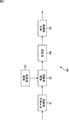
- FIG. 3 is a block diagram illustrating a functional configuration example of a visual impairment processing unit that performs processing in the visual impairment setting mode realized by the smartphone 10.
- the 3 includes a blur degree acquisition unit 61, a coefficient acquisition unit 62, a coefficient storage unit 63, a generation unit 64, and a display control unit 65.
- the blur degree acquisition unit 61, the coefficient acquisition unit 62, the generation unit 64, and the display control unit 65 are realized by, for example, the control unit 22 in FIG. 1, and the coefficient storage unit 63 is realized by, for example, the recording unit 20.
- the blur degree acquisition unit 61 operates the touch panel 21 and moves the knob 43 in the visual impairment setting screen 40 in FIG. 2 to input the blur. Is obtained and supplied to the coefficient obtaining unit 62.
- the coefficient acquisition unit 62 reads out the filter coefficient corresponding to the degree of blur from the coefficient storage unit 63 based on the degree of blur supplied from the blur degree acquisition unit 61, and sets it as the current filter coefficient.
- the coefficient acquisition unit 62 supplies the current filter coefficient to the generation unit 64.
- the coefficient storage unit 63 stores filter coefficients corresponding to the degree of blur that can be input by the user.
- the generating unit 64 generates an image for visual impairment by performing an inverse filter process such as a Wiener filter process on the image 41 being displayed using the filter coefficient supplied from the coefficient acquiring unit 62.
- an inverse filter process such as a Wiener filter process
- the image being displayed is the original image
- the image for visual impairment for the image to be displayed has already been generated
- the image being displayed is It is an image for visual impairment generated last time with respect to a display target image.
- the generation unit 64 supplies the generated visual impairment image to the display control unit 65.
- the display control unit 65 displays the visual impairment setting screen 40 on the touch panel 21. Further, the display control unit 65 supplies the visual impairment image generated by the generation unit 64 to the touch panel 21 and displays it as the image 41 of the visual impairment setting screen 40.
- Filter coefficients corresponding to the degree of blur that can be input by the user are generated based on a PSF (Point Spread Function) representing the blur.
- PSF Point Spread Function
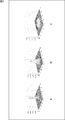
- FIG. 4 is a diagram illustrating an example of a PSF representing each degree of blur that can be input by the user.
- FIG. 4 there are three types of blur degrees that can be input by the user: mild, medium, and severe.
- 4A shows a mildly blurred PSF
- FIG. 4B shows a moderately blurred PSF
- FIG. 4C shows a severely blurred PSF.
- the ⁇ of the PSF is smaller as the degree of blur is lighter.
- the filter coefficient corresponding to each degree of blur is generated by the following equation (1) using the value after FFT (Fast Fourier Transform) processing of the PSF corresponding to the degree of blur.
- Equation (1) Coef is a filter coefficient of the Wiener filter process
- H is a PSF after the FFT process. According to the equation (1), it is possible to generate a filter coefficient of the Wiener filter process for removing the blur from the image where the blur represented by the PSF is generated.
- the generation unit 64 performs an FFT process on the image being displayed, and uses the filter coefficient corresponding to the degree of blur input by the user, using the following equation (2), the image being displayed after the FFT process:
- the Wiener filter processing deconvolution
- Coef is a filter coefficient corresponding to the degree of blur input by the user
- F is an image being displayed after FFT processing.
- Expression (2) it is possible to remove the blur represented by the PSF that has occurred in the displayed image.
- the blur represented by the PSF does not occur in the image being displayed, and it appears to the user with visual impairment as if the blur represented by the PSF has occurred in the image being displayed. . Therefore, according to the expression (2), a visually impaired image that appears to have no blur represented by the PSF to a user who has a visually impaired appearance that the blurred image represented by the PSF appears in the displayed image. The value after FFT processing can be obtained.
- the generation unit 64 performs an IFFT (Inverse Fast Fourier transform) process on the image for visual impairment after the FFT process obtained as a result of the Wiener filter process, and generates an image for visual impairment.
- IFFT Inverse Fast Fourier transform
- the visually impaired image generated in this way has larger blur as the degree of blur input by the user is heavier.
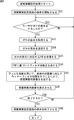
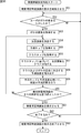
- FIG. 5 is a flowchart for explaining the visual impairment setting process of the smartphone 10 of FIG. This visual impairment setting process is started, for example, when the user commands the start of the visual impairment setting mode by operating the touch panel 21.
- step S ⁇ b> 11 the display control unit 65 (FIG. 3) of the smartphone 10 generates the visual impairment setting screen 40 and supplies it to the touch panel 21, thereby starting display of the visual impairment setting screen 40.
- the image 41 displayed on the visual impairment setting screen 40 may be an image currently displayed, or may be an image for a predetermined visual impairment setting process.
- step S ⁇ b> 12 the blur degree acquisition unit 61 inputs the degree of blur by the user operating the touch panel 21 and moving the knob 43 in the visual impairment setting screen 40 based on the operation signal from the touch panel 21. Determine if you did.
- step S12 If it is determined in step S12 that the user has not yet input the degree of blur, the blur degree acquisition unit 61 waits until the degree of blur is input. On the other hand, if it is determined in step S12 that the user has input the degree of blur, the process proceeds to step S13.
- step S ⁇ b> 13 the blur degree acquisition unit 61 acquires the degree of blur input by the user and supplies it to the coefficient acquisition unit 62.
- step S ⁇ b> 14 the coefficient acquisition unit 62 reads out the filter coefficient corresponding to the degree of blur from the coefficient storage unit 63 based on the degree of blur supplied from the blur degree acquisition unit 61 and sets it as the current filter coefficient. .
- the coefficient acquisition unit 62 supplies the current filter coefficient to the generation unit 64.
- step S15 the generation unit 64 generates a visual impairment image by performing the Wiener filter process on the image 41 being displayed using the filter coefficient supplied from the coefficient acquisition unit 62.
- the generation unit 64 supplies the generated visual impairment image to the display control unit 65.
- step S ⁇ b> 16 the display control unit 65 supplies the image for visual impairment generated by the generation unit 64 to the touch panel 21 and displays it as the image 41 of the visual impairment setting screen 40.
- step S ⁇ b> 17 the control unit 22 (FIG. 1) of the smartphone 10 determines whether to end the visual impairment setting process, for example, whether the user has commanded the end of the visual impairment setting mode by operating the touch panel 21. To do.
- step S17 If it is determined in step S17 that the visual impairment setting process is not terminated, the process returns to step S12, and the processes in steps S12 to S17 are repeated until it is determined that the visual impairment setting process is terminated.
- step S18 the display control unit 65 ends the display of the visual impairment setting screen 40 on the touch panel 21 and the process ends.
- the control unit 22 After the visual impairment setting process, the control unit 22 generates a visual impairment image by performing a Wiener filter process on the original image to be displayed using the current filter coefficient, and instead of the original image to be displayed. It is supplied to the touch panel 21 and displayed.
- the smartphone 10 acquires the degree of blur caused by the visual impairment of the user in the image displayed on the touch panel 21, and generates a visual impairment image based on the degree of blur and the image being displayed. To do. Therefore, an image suitable for a user with a visual impairment can be easily displayed as compared with the case where a large number of parameters need to be acquired in order to generate a visual impairment image. As a result, the processing cost and manufacturing cost of the smartphone 10 are reduced, and the hurdle to commercialization is reduced.
- the smartphone 10 uses a filter coefficient generated based on the PSF corresponding to the degree of blur input by the user, and from the displayed image in which the blur represented by the PSF does not actually occur, A visual impairment image is generated by performing a Wiener filter process for removing blur. Therefore, it is possible to generate a visual impairment image with a simple architecture as compared with a case where a visual impairment image is generated based on a mechanism for identifying blur due to visual impairment. In addition, even if an unexpected parameter contributes to the occurrence of blur due to visual impairment, a highly accurate image for visual impairment can be generated.
- the smartphone 10 can generate a visual impairment image by inputting the degree of blurring of the image being displayed by the user. Therefore, even when the accuracy of the image for visual impairment generated last time with respect to the image to be displayed is not good, by inputting the degree of blur again for the image for visual impairment, high-precision visual A fault image can be generated.
- the parameter that the user needs to input in order to generate the image for visual impairment in the smartphone 10 is the degree of blur, the user can input the parameter intuitively.
- the filter coefficient is stored in the recording unit 20 included in the smartphone 10.
- the filter coefficient may be stored in a server outside the smartphone 10.
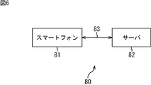
- FIG. 6 is a block diagram illustrating a configuration example of an information processing system including a second embodiment of a smartphone as an image processing apparatus to which the present disclosure is applied.
- a smartphone 81 and a server 82 are connected via a network 83.
- the smartphone 81 does not previously store filter coefficients corresponding to the degree of blur that can be input by the user, but when the degree of blur is input by the user, A filter coefficient corresponding to the degree is generated.
- the smartphone 81 of the information processing system 80 acquires the degree of blur input by a user with visual impairment when performing processing in the visual impairment setting mode.
- the smartphone 81 transmits the obtained degree of blur to the server 82 via the network 83.
- the smartphone 81 receives the PSF corresponding to the degree of blur transmitted from the server 82 in response to the transmission of the degree of blur.
- the smartphone 81 generates a filter coefficient based on the received PSF and sets the current filter coefficient.
- the smartphone 81 generates and displays an image for visual impairment by performing an inverse filter process on the currently displayed image using the current filter coefficient.
- the smartphone 81 After the processing in the visual impairment setting mode is completed, the smartphone 81 generates an image for visual impairment by performing an inverse filter process on the original image to be displayed using the current filter coefficient. Then, the smartphone 81 displays an image for visual impairment instead of the original image to be displayed.
- the server 82 stores a PSF corresponding to each degree of blur that can be input by the user of the smartphone 81.
- the server 82 receives the degree of blur transmitted from the smartphone 81.
- the server 82 reads out the PSF corresponding to the received degree of blur and transmits it to the smartphone 81.
- the configuration of the smartphone 81 is the same as that of the smartphone 10 in FIG. 1 except for the functional configuration of the visual impairment processing unit. Therefore, hereinafter, each hardware block of the smartphone 10 of FIG. 1 will be described as each hardware block of the smartphone 81.
- FIG. 7 is a block diagram illustrating a functional configuration example of the visual impairment processing unit realized by the smartphone 81.
- the transmission unit 101 and the reception unit 102 are realized by the communication unit 12, for example, and the coefficient generation unit 103 is realized by the control unit 22, for example.
- the transmission unit 101 of the visual impairment processing unit 100 performs modulation processing or frequency conversion processing of the degree of blur acquired by the blur degree acquisition unit 61, and generates a transmission signal.
- the transmission unit 101 transmits the transmission signal to the server 82 via the antenna 11, a base station (not shown), the network 83, and the like.
- the reception unit 102 receives a PSF reception signal corresponding to the degree of blur transmitted from the server 82 via the network 83, a base station (not shown), the antenna 11, and the like. To do.
- the receiving unit 102 acquires the PSF by performing amplification, frequency conversion processing, demodulation processing, and the like of the received signal, and supplies the PSF to the coefficient generation unit 103.
- the coefficient generation unit 103 generates a filter coefficient according to the above-described equation (1) based on the PSF supplied from the reception unit 102.
- the coefficient generation unit 103 sets the generated filter coefficient to the current filter coefficient and supplies the generated filter coefficient to the generation unit 64.
- FIG. 8 is a flowchart for explaining the visual impairment setting process of the smartphone 81 of FIG. This visual impairment setting process is started, for example, when the user commands the start of the visual impairment setting mode by operating the touch panel 21.
- steps S31 to S33 Since the processing of steps S31 to S33 is the same as the processing of steps S11 to S13 in FIG.
- step S34 the transmission unit 101 generates a transmission signal by performing modulation processing or frequency conversion processing of the degree of blur acquired by the blur degree acquisition unit 61, and transmits the antenna 11, a base station (not shown), the network 83, and the like. To the server 82.
- step S35 the receiving unit 102 transmits a PSF corresponding to the degree of blur transmitted from the server 82 via the network 83, a base station (not shown), the antenna 11 or the like in response to the transmission of the degree of blur.
- the receiving unit 102 acquires the PSF by performing amplification, frequency conversion processing, demodulation processing, and the like of the received signal, and supplies the PSF to the coefficient generation unit 103.
- step S36 the coefficient generation unit 103 generates a filter coefficient according to the above-described equation (1) based on the PSF supplied from the reception unit 102.
- the coefficient generation unit 103 sets the generated filter coefficient to the current filter coefficient and supplies the generated filter coefficient to the generation unit 64.
- steps S37 to S40 Since the processing of steps S37 to S40 is the same as the processing of steps S15 to S18 in FIG.
- the smartphone 81 acquires the degree of blur caused by the visual impairment of the user in the image displayed on the touch panel 21, and generates a visual impairment image based on the degree of blur and the image being displayed. To do. Therefore, an image suitable for a user with a visual impairment can be easily displayed as compared with the case where a large number of parameters need to be acquired in order to generate a visual impairment image.
- the smartphone 81 since the smartphone 81 generates the filter coefficient based on the PSF corresponding to the degree of blur, it is not necessary to hold the filter coefficient.
- ⁇ Third Embodiment> (Functional configuration example of the visual impairment processing unit of the third embodiment of the smartphone)
- the configuration of the third embodiment of the smartphone as the image processing device to which the present disclosure is applied is the same as that of the smartphone 10 in FIG. 1 except for the functional configuration of the visual impairment processing unit. Therefore, in the following description, each block of hardware of the smartphone 10 in FIG. 1 is used as each block of hardware of the smartphone according to the third embodiment.
- FIG. 9 is a block diagram illustrating a functional configuration example of the visual impairment processing unit according to the third embodiment of the smartphone.
- the visual impairment processing unit 120 in FIG. 9 includes a blur degree acquisition unit 61, a display control unit 65, a class tap extraction unit 121, a class classification unit 122, a coefficient storage unit 123, a coefficient acquisition unit 124, a prediction tap extraction unit 125, and a generation.
- the unit 126 is configured.
- the class tap extraction unit 121, the class classification unit 122, the coefficient acquisition unit 124, the prediction tap extraction unit 125, and the generation unit 126 are realized by the control unit 22, for example, and the coefficient storage unit 123 is realized by the recording unit 20, for example.
- the visual impairment processing unit 120 generates an image for visual impairment from the image being displayed by class classification adaptation processing, not Wiener filter processing.
- the class tap extraction unit 121 of the visual impairment processing unit 120 sequentially sets each pixel of the predicted visual impairment image as a target pixel.
- the class tap extraction unit 121 determines one or more pixel values used for classifying the pixel value of each pixel of the target pixel into one of one or more classes from the displayed image. Get as a class tap. Then, the class tap extraction unit 121 supplies the class tap to the class classification unit 122.
- the class classification unit 122 classifies the pixel value of the target pixel based on the class tap supplied from the class tap extraction unit 121.
- the class classification unit 122 supplies the class obtained as a result to the coefficient acquisition unit 124.
- ADRC Adaptive Dynamic Range Coding
- DCT Discrete Cosine Transform
- VQ Vector Quantization
- DPCM differential pulse code modulation
- the coefficient storage unit 123 stores, as filter coefficients, prediction coefficients for each class and degree of blur obtained by learning described later with reference to FIGS.
- the coefficient acquisition unit 124 reads out the prediction coefficient corresponding to the class supplied from the class classification unit 122 and the degree of blur acquired by the blur degree acquisition unit 61 from the coefficient storage unit 123 and supplies the prediction coefficient to the generation unit 126.
- the prediction tap extraction unit 125 acquires one or more pixel values used for predicting the pixel value of the target pixel as a prediction tap from the image being displayed. Then, the prediction tap extraction unit 125 supplies the prediction tap to the generation unit 126.
- the generation unit 126 uses the prediction coefficient supplied from the coefficient acquisition unit 124 to perform predetermined prediction for obtaining a true prediction value of the pixel value of the target pixel. The calculation is performed as a filter process. Accordingly, the generation unit 126 generates a predicted value of the pixel value of the target pixel as the pixel value of the target pixel of the image for visual impairment, and supplies the generated value to the display control unit 65.
- the pixel value y of each pixel of the image for visual impairment is obtained by the following linear linear expression.
- x i represents the i-th pixel value among the pixel values constituting the prediction tap for the pixel value y
- W i is multiplied by the i-th pixel value.
- n represents the number of pixel values constituting the prediction tap. The same applies to the expressions described later.
- the predicted value of the pixel value of the pixel of the image for visual impairment of the k-th sample is expressed as y k ′
- the predicted value y k ′ is expressed by the following formula (4).
- x ki represents the i-th pixel value among the pixel values constituting the prediction tap for the true value of the predicted value y k ′. The same applies to the equations described later.
- Predictive coefficient W i of the prediction error e k to be 0 in Equation (5) is, although the optimal to predict the true value y k, when the number of samples for learning smaller than n, the prediction coefficients W i is not uniquely determined.
- the optimum prediction coefficient W i is expressed by the square error represented by the following equation (6). Can be obtained by minimizing the sum E of
- the minimum value (local minimum value) of the sum E of square errors in equation (6) is given by W i , which is 0 as a result of partial differentiation of the sum E by the prediction coefficient W i as shown in equation (7) below. It is done.
- equation (7) can be expressed in the form of a determinant as in the following equation (10).
- the normal equation of Expression (10) is a true value y k of a predicted value y k ′ of a pixel value of each pixel of the image for visual impairment, a pixel value x ki constituting a prediction tap corresponding to the pixel, and a prediction coefficient W. It is a formula showing the relationship of i .
- Normal equation of Equation (10) for example, by using a general matrix solution such as sweep-out method (Gauss-Jordan elimination) can be solved for the prediction coefficient W i.
- learning of the optimal prediction coefficients W i for each degree of class and blur can be performed by solving the normal equations in equation (10) for each degree of class and blur.
- the pixel value y can be obtained not by the linear primary expression shown in Expression (3) but by a higher order expression of the second or higher order.
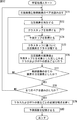
- FIG. 10 is a flowchart illustrating the visual impairment setting process of the third embodiment of the smartphone. This visual impairment setting process is started, for example, when the user commands the start of the visual impairment setting mode by operating the touch panel 21.
- step S54 the class tap extraction unit 121 of the visual impairment processing unit 120 determines, as a target pixel, a pixel that has not yet been selected as a target pixel among the pixels of the visual impairment image to be predicted.
- step S55 the prediction tap extraction unit 125 acquires, as a prediction tap, one or more pixel values used to predict the pixel value of the target pixel from the display target image. Then, the prediction tap extraction unit 125 supplies the prediction tap to the generation unit 126.
- step S56 the class tap extraction unit 121 acquires, from the display target image, one or more pixel values used for classifying the pixel value of the target pixel as a class tap. Then, the class tap extraction unit 121 supplies the class tap to the class tap extraction unit 121.
- step S57 the class classification unit 122 classifies the pixel value of the target pixel based on the class tap supplied from the class tap extraction unit 121.
- the class classification unit 122 supplies the class obtained as a result to the coefficient acquisition unit 124.
- step S58 the coefficient acquisition unit 124 corresponds to the class supplied from the class classification unit 122 and the degree of blur acquired by the blur degree acquisition unit 61 among the prediction coefficients stored in the coefficient storage unit 123. Read the prediction coefficient. Then, the coefficient acquisition unit 124 supplies the read prediction coefficient to the generation unit 126.
- step S ⁇ b> 59 the generation unit 126 uses the prediction tap supplied from the prediction tap extraction unit 125 and the prediction coefficient supplied from the coefficient acquisition unit 124 to perform the calculation of Equation (3) described above as a predetermined prediction calculation. Do as. Accordingly, the generation unit 126 generates a predicted value of the pixel value of the target pixel as the pixel value of the target pixel of the image for visual impairment, and supplies the generated value to the display control unit 65.
- step S60 the prediction tap extraction unit 125 determines whether or not all the pixels of the image for visual impairment are the target pixels. If it is determined in step S60 that all the pixels in the image for visual impairment are not yet the target pixel, the process returns to step S54, and steps S54 to S60 are performed until all the pixels in the image for visual impairment are set as the target pixel. Repeat the process.
- step S60 determines whether all pixels in the image for visual impairment are the target pixels. If it is determined in step S60 that all pixels in the image for visual impairment are the target pixels, the process proceeds to step S61.
- steps S61 to S63 Since the processing of steps S61 to S63 is the same as the processing of steps S16 to S18 in FIG.
- the third embodiment of the smartphone acquires the degree of blur caused by the visual impairment of the user in the image displayed on the touch panel 21, and visually determines based on the degree of blur and the image being displayed. Generate a fault image. Therefore, an image suitable for a user with a visual impairment can be easily displayed as compared with the case where a large number of parameters need to be acquired in order to generate a visual impairment image.
- FIG. 11 is a block diagram illustrating a configuration example of the learning device 140 that learns the prediction coefficient stored in the coefficient storage unit 123 of FIG. 9.
- 11 includes a learning pair storage unit 141, a class tap extraction unit 142, a class classification unit 143, a prediction tap extraction unit 144, a normal equation generation unit 145, a coefficient generation unit 146, and a coefficient storage unit 147. .
- the learning pair storage unit 141 of the learning device 140 stores a pair of a student image and a teacher image for each degree of blur as a learning image used for learning a prediction coefficient.
- an image corresponding to the original image that is the display target image in the third embodiment of the smartphone is used as the student image.
- the teacher image an ideal image for visual impairment for each degree of blur generated from the student image, that is, an image corresponding to the image for visual impairment generated for each degree of blur by the generation unit 126 in FIG. Used.
- the learning pair storage unit 141 supplies the student image of the pair to the class tap extraction unit 142 and the prediction tap extraction unit 144, and supplies the teacher image to the normal equation generation unit 145.
- the class tap extraction unit 142 sequentially sets each pixel of the teacher image that forms a pair with the student image supplied from the learning pair storage unit 141 as a target pixel. Similar to the class tap extraction unit 121 in FIG. 9, the class tap extraction unit 142 acquires, as a class tap, one or more pixel values used for classifying the pixel value of the target pixel from the student image, and the class classification unit 143.
- the class classification unit 143 classifies the pixel value of the target pixel based on the class tap supplied from the class tap extraction unit 142, and classifies the resulting class as a normal equation. It supplies to the production
- the prediction tap extraction unit 144 predicts one or more pixel values used to predict the pixel value of the target pixel from the student image supplied from the learning pair storage unit 141. Obtained as a tap and supplied to the normal equation generation unit 145.
- the normal equation generation unit 145 includes the target pixel for the pixel value of the target pixel of the teacher image supplied from the learning pair storage unit 141 and the prediction tap supplied from the prediction tap extraction unit 144. This is performed for each class from the degree of blur corresponding to the teacher image and the class classification unit 143.
- the coefficient generation unit 146 finds an optimal prediction coefficient for each class and degree of blur by solving the normal equation for each class and degree of blur supplied from the normal equation generation unit 145, and supplies it to the coefficient storage unit 147. To do.
- the coefficient storage unit 147 stores the prediction coefficient for each class and degree of blur supplied from the coefficient generation unit 146.
- the prediction coefficient for each class and degree of blur is stored in the coefficient storage unit 123 of FIG.
- FIG. 12 is a flowchart illustrating the learning process of the learning device 140 in FIG.
- the learning pair storage unit 141 of the learning device 140 reads a pair of student images and teacher images that has not been read yet, from the stored pairs of student images and teacher images.
- the learning pair storage unit 141 supplies the read student image to the class tap extraction unit 142 and the prediction tap extraction unit 144, and supplies the teacher image to the normal equation generation unit 145.
- step S72 the class tap extraction unit 142 determines, as a target pixel, a pixel that has not yet been set as a target pixel among the pixels of the teacher image that form a pair with the student image supplied from the learning pair storage unit 141.
- step S73 the class tap extraction unit 142 acquires the class tap of the target pixel from the student image supplied from the learning pair storage unit 141, and supplies the class tap to the class classification unit 143.
- step S ⁇ b> 74 the prediction tap extraction unit 144 acquires the prediction tap of the target pixel from the student image supplied from the learning pair storage unit 141 and supplies the prediction tap to the normal equation generation unit 145.
- step S75 the class classification unit 143 classifies the pixel of interest based on the class tap supplied from the class tap extraction unit 142, and supplies the resulting class to the normal equation generation unit 145.
- step S76 the normal equation generation unit 145 adds the pixel values of the target pixel in the teacher image supplied from the learning pair storage unit 141 and the prediction tap supplied from the prediction tap extraction unit 144 as targets. Is performed for each degree of blur corresponding to the teacher image including the class and the target pixel from the class classification unit 143.
- step S77 the normal equation generation unit 145 determines whether or not all the pixels of the teacher image are the target pixel. If it is determined in step S77 that not all the pixels of the teacher image have been set as the target pixel, the process returns to step S72, and the processes in steps S72 to S77 are repeated until all the pixels are set as the target pixel.
- step S77 if it is determined in step S77 that all the pixels of the teacher image are the target pixels, the process proceeds to step S78.
- step S78 the normal equation generation unit 145 determines whether all pairs stored in the learning pair storage unit 141 have been read.
- step S78 If it is determined in step S78 that all pairs have not yet been read, the process returns to step S71, and the processes in steps S71 to S78 are repeated until all pairs are read.
- the normal equation generation unit 145 generates the normal equation of equation (10) for each class and degree of blur generated by adding in step S76. Is supplied to the coefficient generation unit 146.
- step S79 the coefficient generation unit 146 solves the normal equation of the equation (10) for each class and degree of blur supplied from the normal equation generation unit 145, and obtains an optimal prediction coefficient for each class and degree of blur. Ask.
- step S80 the coefficient generation unit 146 supplies the optimum prediction coefficient for each obtained class and degree of blur to the coefficient storage unit 147 for storage. Then, the process ends.
- a pair of a student image and a teacher image is stored for each degree of blur.
- a pair of a student image and a teacher image for each degree of blur corresponding to the student image. It may be stored. That is, since the student image is common to all the degrees of blur, only one student image may be stored for all the degrees of blur.
- an image for visual impairment is generated for the image 41 on the visual impairment setting screen 40 and displayed as the image 41.
- An image may be generated and displayed as the visual impairment setting screen 40.
- the blur generated on the Blur bar 42 and the knob 43 due to the visual impairment of the user can also be removed.
- ⁇ Fourth embodiment> (Functional configuration example of the visual impairment processing unit of the fourth embodiment of the smartphone)
- the configuration of the fourth embodiment of the smartphone as the image processing apparatus to which the present disclosure is applied is the same as that of the smartphone 10 in FIG. 1 except for the functional configuration of the visual impairment processing unit. Therefore, below, each block of the hardware of the smart phone 10 of FIG. 1 is used also as each block of the hardware of the fourth embodiment of the smart phone.
- FIG. 13 is a block diagram illustrating a functional configuration example of the visual impairment processing unit according to the fourth embodiment of the smartphone.
- the configuration of the visual impairment processing unit 160 in FIG. 13 is that a position acquisition unit 161 is provided instead of the blur degree acquisition unit 61, and a coefficient generation unit 162 is provided instead of the coefficient acquisition unit 62 and the coefficient storage unit 63.
- a display control unit 163 is provided instead of the display control unit 65, but is different from the configuration of the visual impairment processing unit 60 in FIG.
- the position acquisition unit 161, the coefficient generation unit 162, and the display control unit 163 are realized by the control unit 22, for example.
- the visual impairment processing unit 160 is not the PSF corresponding to the degree of blur, but the optimum use position that is the use position of the touch panel 21 when the blur due to the visual impairment of the user does not occur and the normal use position of the user touch panel 21. Based on this, a filter coefficient is generated.
- the position acquisition unit 161 acquires, from the touch panel 21, an operation signal that represents a visual failure setting mode start command input by the user operating the touch panel 21. In response to the operation signal, the position acquisition unit 161 supplies a shooting preparation operation start command to the front camera of the camera unit 16 to start the shooting preparation operation.
- the position acquisition unit 161 acquires, from the touch panel 21, an operation signal representing a shooting command (shutter command) input by the user operating the touch panel 21. In accordance with the operation signal, the position acquisition unit 161 determines the distance between the subject obtained by the AF operation from the front camera of the camera unit 16 and the camera unit 16 as the optimal use position information or the normal use position. Is acquired as the normal use position information representing. The position acquisition unit 161 supplies the acquired optimal use position information and normal use position information to the coefficient generation unit 162.
- the coefficient generation unit 162 generates a PSF representing blur due to the visual impairment of the user based on the optimal use position information and the normal use position information supplied from the position acquisition unit 161.
- the coefficient generation unit 162 generates a filter coefficient based on the generated PSF according to the above-described equation (1).
- the coefficient generation unit 162 sets the generated filter coefficient to the current filter coefficient and supplies it to the generation unit 64.
- the display control unit 163 causes the touch panel 21 to display a normal use position setting screen for setting normal use position information and an optimum use position setting screen for setting optimum use position information. In addition, the display control unit 163 causes the touch panel 21 to display the visual impairment image supplied from the generation unit 64.
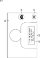
- FIG. 14 is a diagram illustrating an example of a normal use position setting screen.
- an image 181 obtained by provisional shooting or actual shooting of the front camera of the camera unit 16 is displayed.
- a shutter button 182, a mode button 183, and the like are displayed superimposed on the image display area 181.
- the shutter button 182 is a button operated when the user inputs a shooting command.
- the mode button 183 is a button representing the current mode. In the normal use position setting screen 180, the mode button 183 has an eye mark representing the visual impairment setting mode.
- the normal use position setting screen 180 is superimposed on the image 181 with, for example, a message portion 184 in which a message “Please press the shutter button at the normal use position” is described. .
- the position acquisition unit 161 acquires the distance from the subject to the front camera measured by the AF operation, that is, the distance between the user and the touch panel 21 as normal use position information.
- FIG. 15 is a diagram illustrating an example of the optimum use position setting screen.
- the user grips the touch panel 21 at the optimum use position and operates the shutter button 182 according to the message displayed on the message unit 201.
- the position acquisition unit 161 acquires the distance from the subject to the front camera measured by the AF operation, that is, the distance between the user and the touch panel 21 as optimal use position information.
- FIG. 16 is a diagram illustrating generation of PSF by the coefficient generation unit 162 in FIG.
- ⁇ c is an angle formed by the lens surface of the eye and the light directed from the point light source M at the optimum use position on the optical axis.
- ⁇ e is an angle formed by the lens surface of the eye and the light from the point light source M traveling from the lens surface of the eye toward the image plane on the retina of the eye.
- ⁇ n is an angle formed by the lens surface of the eye and the light directed to the eye from the point light source M ′ at the normal use position on the optical axis.
- ⁇ p is an angle formed by the lens surface of the eye and the light from the point light source M ′ that travels from the lens surface of the eye toward the image plane on the retina of the eye.
- de is the distance between the lens surface of the eye and the image plane on the retina, as shown in FIG. dc is the distance between the optimal use position and the eye lens, and dn is the distance between the normal use position and the eye lens.
- the radius r of the image formed on the image plane on the retina of the eye by the light from the point light source M ′ is expressed by the following equation (15).
- focal length f of the point light source M ′ is expressed by the following equation (16).
- the radius r d of the light source at the normal use position corresponding to the image of the radius r formed on the image plane, that is, the blur caused by the visual disturbance at the normal use position is Using the focal length f, it is expressed by the following equation (17).
- Equation (17) by substituting Equation (14) to (16), the radius A of the eye lens, as the distance d e of the image surface on the lens of the eye and the retina, and substituting a predetermined value, obtains the radius r d
- the expression is an expression having the distance dc and the distance dn as variables.
- the coefficient generation unit 162 first substitutes the distance represented by the optimal use position information for the distance dc in this equation, and substitutes the distance represented by the normal use position information for the distance dn, so that the user can visually recognize the normal use position.
- a radius r d of blur caused by the failure is obtained.
- the coefficient generation unit 162, by dividing the radius r d is the absolute radius pixel size of the touch panel 21, and converts the pixel number r p.
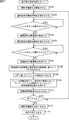
- FIG. 17 is a flowchart illustrating the visual impairment setting process of the fourth embodiment of the smartphone. This visual impairment setting process is started, for example, when the user commands the start of the visual impairment setting mode by operating the touch panel 21.
- step S101 of FIG. 17 the position acquisition unit 161 supplies the front camera of the camera unit 16 with a start command for the shooting preparation operation, and starts the shooting preparation operation.
- step S102 the display control unit 163 displays the normal use position setting screen 180.
- step S103 the position acquisition unit 161 determines whether the shutter button 182 has been operated by the user. If the position acquisition unit 161 has not acquired from the touch panel 21 an operation signal representing a shooting command input by operating the shutter button 182 by the user, it is determined in step S103 that the shutter button 182 has not been operated yet. To do. Then, the position acquisition unit 161 stands by until the operation signal is acquired.
- the position acquisition unit 161 acquires from the touch panel 21 an operation signal representing a shooting command input by operating the shutter button 182 by the user, it determines that the shutter button 182 has been operated in step S103. Then, the display control unit 163 deletes the message unit 184 in the normal use position setting screen 180 and advances the process to step S104.
- step S104 the position acquisition unit 161 acquires, from the front camera of the camera unit 16, the distance between the subject obtained by the AF operation of the shooting preparation operation and the camera unit 16 as normal use position information.
- the position acquisition unit 161 supplies the acquired normal use position information to the coefficient generation unit 162.
- step S105 the display control unit 163 displays the optimum use position setting screen 200 on the touch panel 21 instead of the normal use position setting screen 180 from which the message unit 184 has been deleted.
- step S106 the position acquisition unit 161 determines whether the user has operated the shutter button 182 as in the process of step S103.
- step S103 If it is determined in step S103 that the shutter button 182 has not been operated yet, the position acquisition unit 161 waits until the shutter button 182 is operated. On the other hand, when it is determined in step S103 that the shutter button 182 has been operated, the display control unit 163 deletes the message unit 201 in the optimum use position setting screen 200, and the process proceeds to step S107.
- step S107 the position acquisition unit 161 acquires, from the front camera of the camera unit 16, the distance between the subject obtained by the AF operation of the shooting preparation operation and the camera unit 16 as optimum use position information.
- the position acquisition unit 161 supplies the acquired optimum use position information to the coefficient generation unit 162.
- step S108 the coefficient generation unit 162 generates a PSF representing the blur due to the user's visual impairment based on the optimal use position information and the normal use position information supplied from the position acquisition unit 161.
- step S109 the coefficient generation unit 162 generates a filter coefficient according to the above-described equation (1) based on the PSF.
- the coefficient generation unit 162 sets the generated filter coefficient to the current filter coefficient and supplies it to the generation unit 64.
- step S110 the generation unit 64 generates a visual impairment image by performing a Wiener filter process on the image 181 being displayed using the filter coefficient supplied from the coefficient generation unit 162.
- the generation unit 64 supplies the generated visual impairment image to the display control unit 163.
- step S111 the display control unit 163 supplies the visual impairment image generated by the generation unit 64 to the touch panel 21, and displays it as the image 181 of the optimum use position setting screen 200.
- step S112 the control unit 22 determines whether to end the visual impairment setting process, for example, whether the user has commanded the end of the visual impairment setting mode by operating the touch panel 21.
- step S112 If it is determined in step S112 that the visual impairment setting process is not terminated, the process returns to step S102, and the display control unit 163 replaces the optimum use position setting screen 200 from which the message part 201 has been deleted with the normal use position setting. A screen 180 is displayed on the touch panel 21. And the process of step S103 thru
- step S113 the position acquisition unit 161 supplies a shooting preparation operation end command to the front camera of the camera unit 16 to end the shooting preparation operation.
- step S114 the display control unit 163 ends the display of the optimum use position setting screen 200 from which the message unit 201 has been deleted, and ends the process.
- the smartphone generates the PSF, but an external server may generate the PSF.
- the smartphone transmits the optimal use position information and the normal use position information to an external server, and receives the PSF generated based on the optimum use position information and the normal use position information from the external server.
- the smartphone transmits the optimum use position information and the normal use position information to an external server, and receives a filter coefficient based on the PSF generated based on the optimum use position information and the normal use position information from the external server. You may make it do.
- the normal use position information may not be input by the user but may be determined in advance.
- the display order of the normal use position setting screen and the optimum use position setting screen may be the order of the normal use position setting screen and the optimum use position setting screen as in the case of FIG. The order may be the screen and the normal use position setting screen.
- the fourth embodiment of the smartphone acquires the optimum use position, and displays the visual impairment image based on the optimum use position, the normal use position, and the display target image. Therefore, an image suitable for a user with a visual impairment can be easily displayed as compared with the case where a large number of parameters need to be acquired in order to generate a visual impairment image.
- the step of describing the program stored in the program recording medium is not limited to the processing performed in time series in the order described, but is not necessarily performed in time series. Or the process performed separately is also included.
- the system means a set of a plurality of components (devices, modules (parts), etc.), and it does not matter whether all the components are in the same housing. Accordingly, a plurality of devices housed in separate housings and connected via a network and a single device housing a plurality of modules in one housing are all systems. .
- the present disclosure can take a cloud computing configuration in which one function is shared by a plurality of devices via a network and is processed jointly.
- each step described in the above flowchart can be executed by one device or can be shared by a plurality of devices.
- the plurality of processes included in the one step can be executed by being shared by a plurality of apparatuses in addition to being executed by one apparatus.
- This disclosure can have the following configurations.
- a position acquisition unit that acquires an optimal use position that is a use position of the display device when blur due to a visual impairment of the user does not occur; Based on the optimum use position acquired by the position acquisition unit, the normal use position of the display device, and the image to be displayed, the image for visual impairment in which the blur does not occur in the display device at the normal use position is obtained.
- An image processing apparatus comprising: a display control unit that displays on a display device. (2) The position acquisition unit acquires the normal use position, The display control unit is configured to display the image for visual impairment on the display device based on the optimum use position and the normal use position acquired by the position acquisition unit and the image to be displayed. The image processing apparatus according to (1).
- a generating unit that generates the image for visual impairment by performing a filtering process on the display target image using a filter coefficient generated based on the optimum use position and the normal use position;
- the image processing apparatus according to (1) or (2), wherein the display control unit is configured to cause the display device to display the visual impairment image generated by the generation unit.
- a coefficient generation unit that generates a function representing the blur based on the optimal use position and the normal use position, and generates the filter coefficient based on the function;
- the image processing device according to (3), wherein the generation unit is configured to perform a filter process on the display target image using the filter coefficient generated by the coefficient generation unit.
- the image processing apparatus according to any one of (1) to (4), wherein the position acquisition unit is configured to acquire the optimum use position by an AF operation.
- the image processing device A position acquisition step of acquiring an optimum use position that is a use position of the display device when blurring due to a user's visual impairment does not occur; Based on the optimal use position acquired by the processing of the position acquisition step, the normal use position of the display device, and the image to be displayed, the image for visual impairment in which the blur does not occur in the display device at the normal use position A display control step for displaying the image on the display device.
- Computer A position acquisition unit that acquires an optimal use position that is a use position of the display device when blur due to a visual impairment of the user does not occur; Based on the optimum use position acquired by the position acquisition unit, the normal use position of the display device, and the image to be displayed, the image for visual impairment in which the blur does not occur in the display device at the normal use position is obtained.
- a blur degree acquisition unit that acquires the degree of blur caused by the visual impairment of the user in the image displayed on the display device;
- An image processing apparatus comprising: a display control unit that causes the display device to display an image for visual impairment that does not generate blur based on the degree of blur acquired by the blur degree acquisition unit and an image to be displayed.
- a generation unit that generates the visual impairment image by performing a filtering process on the display target image using a filter coefficient corresponding to the degree of blur acquired by the blur degree acquisition unit;
- the image processing device according to (8), wherein the display control unit is configured to display the visual impairment image generated by the generation unit on the display device.
- a coefficient generation unit that generates the filter coefficient based on a function representing the blur corresponding to the degree of blur acquired by the blur degree acquisition unit;
- the image processing apparatus according to (9), wherein the generation unit performs a filter process on the display target image using the filter coefficient generated by the coefficient generation unit.
- the filter coefficient uses a teacher image corresponding to the image for visual impairment and a student image corresponding to the image to be displayed, a pixel value of each pixel of the teacher image, and the pixel
- the image processing device A blur degree acquisition step for acquiring a degree of blur caused by a visual impairment of the user in an image displayed on the display device; Image processing including: a display control step for causing the display device to display a visual impairment image that does not generate blur based on the degree of blur acquired by the processing of the blur degree acquisition step and an image to be displayed.
- Method. (13) Computer A blur degree acquisition unit that acquires the degree of blur caused by the visual impairment of the user in the image displayed on the display device; Based on the degree of blur acquired by the blur degree acquisition unit and an image to be displayed, the display control unit is configured to function as a display control unit that causes the display device to display an image for visual impairment that does not generate blur. program.
Landscapes
- Engineering & Computer Science (AREA)
- Theoretical Computer Science (AREA)
- Physics & Mathematics (AREA)
- Health & Medical Sciences (AREA)
- General Physics & Mathematics (AREA)
- Life Sciences & Earth Sciences (AREA)
- Biomedical Technology (AREA)
- Molecular Biology (AREA)
- Biophysics (AREA)
- Ophthalmology & Optometry (AREA)
- Human Computer Interaction (AREA)
- Heart & Thoracic Surgery (AREA)
- Medical Informatics (AREA)
- General Engineering & Computer Science (AREA)
- Surgery (AREA)
- Animal Behavior & Ethology (AREA)
- General Health & Medical Sciences (AREA)
- Public Health (AREA)
- Veterinary Medicine (AREA)
- Image Processing (AREA)
Abstract
本開示は、視覚障害を持つユーザに適した画像を容易に表示させることができるようにする画像処理装置、画像処理方法、およびプログラムに関する。 位置取得部は、ユーザの視覚障害によるボケが発生しないときのタッチパネルの使用位置である最適使用位置を取得する。表示制御部は、最適使用位置、タッチパネルの通常使用位置、および表示対象の画像に基づいて、通常使用位置のタッチパネルにおいてボケが発生しない視覚障害用画像をタッチパネルに表示させる。本開示は、例えば、スマートフォン等に適用することができる。
Description
本開示は、画像処理装置、画像処理方法、およびプログラムに関し、特に、視覚障害を持つユーザに適した画像を容易に表示させることができるようにした画像処理装置、画像処理方法、およびプログラムに関する。
スマートフォン等のプライベート用途のディスプレイは、一般的に、近視、老眼などの視覚障害を持たないユーザ向けに設計されている。従って、ユーザは、ディスプレイ使用時に、メガネやコンタクトレンズといった視覚障害を矯正する装置を使用する必要があり、煩わしさを感じることがある。
そこで、コンピュータが、ディスプレイのハードウエア特性を受信するステップ、ユーザの視覚障害を説明する少なくとも1つのパラメータを受信するステップ、そのディスプレイがユーザによって見られるときの状態を説明する少なくとも1つのパラメータを受信するステップ、瞳関数を算出するステップ、点像分布関数(PSF)または光伝達関数(OTF)を算出するステップ、ユーザの視覚障害を補正するために原始画像の少なくとも一部に相当する事前矯正画像を算出するステップ、および事前矯正画像をディスプレイに表現するステップを含む処理を実行する方法が考案されている(例えば、特許文献1参照)。
この方法により、視覚障害を持つユーザのディスプレイに対して、ユーザの視覚障害を補正する事前矯正画像を表示させることができる。その結果、視覚障害を持つユーザは、視覚障害を矯正する装置を使用せずに、ディスプレイを使用することができる。
しかしながら、特許文献1に記載の方法では、多数のパラメータを取得する必要があるため、処理や構成が複雑になり、処理コストや製造コストが高くなる。従って、視覚障害を持つユーザに適した画像を容易に表示させることが望まれている。
本開示は、このような状況に鑑みてなされたものであり、視覚障害を持つユーザに適した画像を容易に表示させることができるようにするものである。
本開示の第1の側面の画像処理装置は、ユーザの視覚障害によるボケが発生しないときの表示装置の使用位置である最適使用位置を取得する位置取得部と、前記位置取得部により取得された前記最適使用位置、前記表示装置の通常使用位置、および表示対象の画像に基づいて、前記通常使用位置の前記表示装置において前記ボケが発生しない視覚障害用画像を前記表示装置に表示させる表示制御部とを備える画像処理装置である。
本開示の第1の側面の画像処理方法およびプログラムは、本開示の第1の側面の画像処理装置に対応する。
本開示の第1の側面においては、ユーザの視覚障害によるボケが発生しないときの表示装置の使用位置である最適使用位置が取得され、取得された前記最適使用位置、前記表示装置の通常使用位置、および表示対象の画像に基づいて、前記通常使用位置の前記表示装置において前記ボケが発生しない視覚障害用画像が前記表示装置に表示される。
本開示の第2の側面の画像処理装置は、表示装置に表示される画像においてユーザの視覚障害により発生するボケの度合を取得するボケ度合取得部と、前記ボケ度合取得部により取得された前記ボケの度合と、表示対象の画像とに基づいて、前記ボケが発生しない視覚障害用画像を前記表示装置に表示させる表示制御部とを備える画像処理装置である。
本開示の第2の側面の画像処理方法およびプログラムは、本開示の第2の側面の画像処理装置に対応する。
本開示の第2の側面においては、表示装置に表示される画像においてユーザの視覚障害により発生するボケの度合が取得され、取得された前記ボケの度合と、表示対象の画像とに基づいて、前記ボケが発生しない視覚障害用画像が前記表示装置に表示される。
本開示の第1および第2の側面によれば、画像を表示させることができる。また、本開示の第1および第2の側面によれば、視覚障害を持つユーザに適した画像を容易に表示させることができる。
なお、ここに記載された効果は必ずしも限定されるものではなく、本開示中に記載されたいずれかの効果であってもよい。
以下、本開示を実施するための形態(以下、実施の形態という)について説明する。なお、説明は以下の順序で行う。
1.第1実施の形態:スマートフォン(図1乃至図5)
2.第2実施の形態:情報処理システム(図6乃至図8)
3.第3実施の形態:スマートフォン(図9乃至図12)
4.第4実施の形態:情報処理システム(図13乃至図17)
1.第1実施の形態:スマートフォン(図1乃至図5)
2.第2実施の形態:情報処理システム(図6乃至図8)
3.第3実施の形態:スマートフォン(図9乃至図12)
4.第4実施の形態:情報処理システム(図13乃至図17)
<第1実施の形態>
(スマートフォンの第1実施の形態のハードウエアの構成例)
図1は、本開示を適用した画像処理装置としてのスマートフォンの第1実施の形態のハードウエアの構成例を示すブロック図である。
(スマートフォンの第1実施の形態のハードウエアの構成例)
図1は、本開示を適用した画像処理装置としてのスマートフォンの第1実施の形態のハードウエアの構成例を示すブロック図である。
スマートフォン10は、通信部12、音声コーデック13、カメラ部16、画像処理部17、記録再生部19、記録部20、タッチパネル21(表示装置)、制御部22を有している。これらは、バス24を介して互いに接続されている。
また、通信部12にはアンテナ11が接続されており、音声コーデック13には、スピーカ14とマイクロホン15が接続されている。さらに、制御部22には、電源ボタンなどの操作部23が接続されている。
スマートフォン10は、通信モード、通話モード、撮影モード、視覚障害設定モードなどの各種のモードの処理を行う。視覚障害設定モードとは、視覚障害を持たないユーザに適した表示対象の画像を、視覚障害を持つユーザに適した画像に変更して表示させるための設定を行うモードである。
スマートフォン10が通話モードの処理を行う場合、マイクロホン15で生成されたアナログの音声信号が、音声コーデック13に入力される。音声コーデック13は、アナログの音声信号をデジタルの音声データへ変換し、変換後の音声データを圧縮して、通信部12に供給する。通信部12は、圧縮後の音声データの変調処理や周波数変換処理等を行い、送信信号を生成する。そして、通信部12は、送信信号をアンテナ11に供給し、図示しない基地局へ送信する。
通信部12はまた、アンテナ11で受信した受信信号の増幅、周波数変換処理、復調処理等を行うことにより、通話相手から送信されたデジタルの音声データを取得し、音声コーデック13に供給する。音声コーデック13は、音声データを伸張し、伸長後の音声データをアナログの音声信号へ変換して、スピーカ14に出力する。
また、スマートフォン10が通信モードの処理としてメール送信を行う場合、制御部22は、ユーザがタッチパネル21を操作することにより入力した文字を受け付け、その文字をタッチパネル21に表示する。また、制御部22は、ユーザがタッチパネル21を操作することにより入力した指示等に基づいて、メールデータを生成し、通信部12に供給する。通信部12は、メールデータの変調処理や周波数変換処理等を行い、得られた送信信号をアンテナ11から送信する。
通信部12はまた、アンテナ11で受信した受信信号の増幅、周波数変換処理、復調処理等を行い、メールデータを復元する。このメールデータは、タッチパネル21に供給され、表示される。
なお、スマートフォン10は、受信したメールデータを、記録再生部19により記録部20に記録させることも可能である。記録部20は、RAM(Random Access Memory)や内蔵型フラッシュメモリ等の半導体メモリ、ハードディスク、磁気ディスク、光磁気ディスク、光ディスク、USB(Universal Serial Bus)メモリ、またはメモリカード等のリムーバブルメディアである。
スマートフォン10が撮影モードの処理を行う場合、制御部22は、撮影準備動作の開始指令を、カメラ部16に供給する。カメラ部16は、通常使用状態におけるスマートフォン10の裏面(タッチパネル21と対向する面)にレンズを有するバックカメラと、表面(タッチパネル21が配置される面)にレンズを有するフロントカメラとからなる。バックカメラは、ユーザが自分以外の被写体を撮影するときに用いられ、フロントカメラは、ユーザが自分を被写体として撮影するときに用いられる。
カメラ部16のバックカメラまたはフロントカメラは、制御部22から供給される撮影準備動作の開始指令に応じて、AF(測距)動作、仮撮影などの撮影準備動作を行う。制御部22は、ユーザがタッチパネル21を操作することにより入力した撮影指令に応じて、撮影指令をカメラ部16に供給する。カメラ部16は、撮影指令に応じて、本撮影を行う。仮撮影や本撮影によって撮影された撮影画像は、タッチパネル21に供給され、表示される。また、本撮影によって撮影された撮影画像は、画像処理部17にも供給され、画像処理部17において符号化される。符号化の結果生成される符号化データは、記録再生部19に供給され、記録部20に記録される。
スマートフォン10が視覚障害設定モードの処理を行う場合、制御部22は、視覚障害を持つユーザがタッチパネル21を操作することにより入力した、タッチパネル21に表示される画像においてユーザの視覚障害により発生するボケの度合を取得する。
即ち、視覚障害を持つユーザが、例えば通常の使用位置で、タッチパネル21に表示される、視覚障害を持たないユーザに適した画像(以下、原画像という)などの、視覚障害を持つユーザに適していない画像を見る場合、ユーザに見える画像にはボケが発生している。ユーザは、このボケの度合を、タッチパネル21を操作することにより入力し、制御部22は、そのボケの度合を取得する。
制御部22は、記録部20に記録されている、ユーザにより入力可能なボケの度合のそれぞれに対応するフィルタ係数のうちの、取得されたボケの度合に対応するフィルタ係数を、記録再生部19に読み出させ、現在のフィルタ係数に設定する。制御部22は、現在のフィルタ係数を用いて、表示中の画像に対して逆フィルタ処理を行うことにより、現在の使用位置のタッチパネル21においてユーザの視覚障害によるボケが発生しない視覚障害用画像を生成し、タッチパネル21に表示させる。
視覚障害設定モードの処理の終了後、制御部22は、現在のフィルタ係数を用いて、表示対象の原画像に対して逆フィルタ処理を行うことにより視覚障害用画像を生成する。そして、制御部22は、表示対象の原画像に代えて視覚障害用画像をタッチパネル21に表示させる。
また、制御部22は、ユーザにより操作部23の電源ボタンが押下された場合、スマートフォン10の電源をオンまたはオフにする。
制御部22は、上述した処理を、例えば記録部20に記録されているプログラムを実行することにより行う。このプログラムは、有線または無線の伝送媒体を介して、通信部12で受信し、記録部20にインストールすることができる。その他、プログラムは、記録部20に、あらかじめインストールしておくことができる。
(視覚障害設定画面の例)
図2は、視覚障害設定モード時にタッチパネル21に表示される視覚障害設定画面の例を示す図である。
図2は、視覚障害設定モード時にタッチパネル21に表示される視覚障害設定画面の例を示す図である。
図2の視覚障害設定画面40には、全面に表示対象の画像41が表示される。また、視覚障害設定画面40には、その画像41に重畳されて、図中上部に、水平方向の位置に応じてボケの度合を表すBlurバー42と、入力するボケの度合を表すつまみ43とが表示される。Blurバー42の位置は、左端に近いほど小さいボケの度合を表し、右端に近いほど大きいボケの度合を表す。
ユーザは、視覚障害設定画面40を見ながらタッチパネル21を操作し、視覚障害設定画面40に発生しているユーザの視覚障害によるボケの度合を表すBlurバー42の位置に、つまみ43を移動させる。これにより、ボケの度合が入力される。
(視覚障害処理部の機能的構成例)
図3は、スマートフォン10が実現する、視覚障害設定モードの処理を行う視覚障害処理部の機能的構成例を示すブロック図である。
図3は、スマートフォン10が実現する、視覚障害設定モードの処理を行う視覚障害処理部の機能的構成例を示すブロック図である。
図3の視覚障害処理部60は、ボケ度合取得部61、係数取得部62、係数記憶部63、生成部64、および表示制御部65により構成される。ボケ度合取得部61、係数取得部62、生成部64、および表示制御部65は、例えば、図1の制御部22により実現され、係数記憶部63は、例えば、記録部20により実現される。
ボケ度合取得部61は、図1のタッチパネル21からの操作信号に基づいて、ユーザが、タッチパネル21を操作して、図2の視覚障害設定画面40内のつまみ43を移動させることにより入力したボケの度合を取得し、係数取得部62に供給する。
係数取得部62は、ボケ度合取得部61から供給されるボケの度合に基づいて、そのボケの度合に対応するフィルタ係数を係数記憶部63から読み出し、現在のフィルタ係数に設定する。係数取得部62は、現在のフィルタ係数を生成部64に供給する。係数記憶部63は、ユーザにより入力可能なボケの度合のそれぞれに対応するフィルタ係数を記憶する。
生成部64は、係数取得部62から供給されるフィルタ係数を用いて、表示中の画像41に対してウィナーフィルタ処理などの逆フィルタ処理を行うことにより、視覚障害用画像を生成する。表示対象の画像に対する視覚障害用画像がまだ生成されていない場合、表示中の画像は原画像であり、表示対象の画像に対する視覚障害用画像が既に生成されている場合、表示中の画像は、表示対象の画像に対して前回生成された視覚障害用画像である。生成部64は、生成された視覚障害用画像を表示制御部65に供給する。
表示制御部65は、視覚障害設定画面40をタッチパネル21に表示させる。また、表示制御部65は、生成部64により生成された視覚障害用画像をタッチパネル21に供給し、視覚障害設定画面40の画像41として表示させる。
(フィルタ係数とウィナーフィルタ処理の説明)
ユーザが入力可能なボケの度合のそれぞれに対応するフィルタ係数は、そのボケを表すPSF(Point Spread Function)(点広がり関数)に基づいて生成される。
ユーザが入力可能なボケの度合のそれぞれに対応するフィルタ係数は、そのボケを表すPSF(Point Spread Function)(点広がり関数)に基づいて生成される。
図4は、ユーザが入力可能なボケの度合それぞれのボケを表すPSFの例を示す図である。
図4の例では、ユーザが入力可能なボケの度合の種類が、軽度、中度、および重度の3種類である。図4のAは、軽度のボケのPSFを示し、図4のBは、中度のボケのPSFを示し、図4のCは、重度のボケのPSFを示す。図4のA乃至図4のCに示すように、ボケの度合が軽いほど、PSFのσは小さい。
各ボケの度合に対応するフィルタ係数は、具体的には、そのボケの度合に対応するPSFのFFT(Fast Fourier Transform)処理後の値を用いて、以下の式(1)により生成される。

なお、式(1)において、Coefは、ウィナーフィルタ処理のフィルタ係数であり、Hは、FFT処理後のPSFである。式(1)によれば、PSFが表すボケが発生している画像からボケを除去するウィナーフィルタ処理のフィルタ係数を生成することができる。
生成部64は、表示中の画像に対してFFT処理を行い、ユーザにより入力されたボケの度合に対応するフィルタ係数を用いて、以下の式(2)により、FFT処理後の表示中の画像に対してウィナーフィルタ処理(逆畳み込み)を行う。

なお、式(2)において、Coefは、ユーザにより入力されたボケの度合に対応するフィルタ係数であり、Fは、FFT処理後の表示中の画像である。
式(2)によれば、表示中の画像に発生している、PSFが表すボケを除去することができる。しかしながら、実際には、表示中の画像にPSFが表すボケは発生しておらず、視覚障害を持つユーザに、あたかも表示中の画像にPSFが表すボケが発生しているように見えるだけである。従って、式(2)によれば、表示中の画像にPSFが表すボケが発生しているように見える視覚障害を持つユーザに、PSFが表すボケが発生していないように見える視覚障害用画像のFFT処理後の値を求めることができる。
生成部64は、ウィナーフィルタ処理の結果得られるFFT処理後の視覚障害用画像に対してIFFT(Inverse Fast Fourier transform)処理を行い、視覚障害用画像を生成する。このようにして生成された視覚障害用画像は、ユーザにより入力されたボケの度合が重いほど、大きいボケを有する。
(スマートフォンの処理の説明)
図5は、図1のスマートフォン10の視覚障害設定処理を説明するフローチャートである。この視覚障害設定処理は、例えば、ユーザがタッチパネル21を操作することにより、視覚障害設定モードの開始を指令したとき、開始される。
図5は、図1のスマートフォン10の視覚障害設定処理を説明するフローチャートである。この視覚障害設定処理は、例えば、ユーザがタッチパネル21を操作することにより、視覚障害設定モードの開始を指令したとき、開始される。
ステップS11において、スマートフォン10の表示制御部65(図3)は、視覚障害設定画面40を生成してタッチパネル21に供給することにより、視覚障害設定画面40の表示を開始させる。このとき、視覚障害設定画面40に表示される画像41は、現在表示中の画像であってもよいし、所定の視覚障害設定処理用の画像であってもよい。
ステップS12において、ボケ度合取得部61は、タッチパネル21からの操作信号に基づいて、ユーザが、タッチパネル21を操作し、視覚障害設定画面40内のつまみ43を移動させることにより、ボケの度合を入力したかどうかを判定する。
ステップS12でユーザがまだボケの度合を入力していないと判定された場合、ボケ度合取得部61は、ボケの度合が入力されるまで待機する。一方、ステップS12でユーザがボケの度合を入力したと判定された場合、処理はステップS13に進む。
ステップS13において、ボケ度合取得部61は、ユーザが入力したボケの度合を取得し、係数取得部62に供給する。ステップS14において、係数取得部62は、ボケ度合取得部61から供給されるボケの度合に基づいて、そのボケの度合に対応するフィルタ係数を係数記憶部63から読み出し、現在のフィルタ係数に設定する。係数取得部62は、現在のフィルタ係数を生成部64に供給する。
ステップS15において、生成部64は、係数取得部62から供給されるフィルタ係数を用いて、表示中の画像41に対してウィナーフィルタ処理を行うことにより、視覚障害用画像を生成する。生成部64は、生成された視覚障害用画像を表示制御部65に供給する。
ステップS16において、表示制御部65は、生成部64により生成された視覚障害用画像をタッチパネル21に供給し、視覚障害設定画面40の画像41として表示させる。
ステップS17において、スマートフォン10の制御部22(図1)は、視覚障害設定処理を終了するかどうか、例えば、ユーザがタッチパネル21を操作することにより視覚障害設定モードの終了を指令したかどうかを判定する。
ステップS17で視覚障害設定処理を終了しないと判定された場合、処理は、ステップS12に戻り、視覚障害設定処理を終了すると判定するまで、ステップS12乃至S17の処理が繰り返される。
一方、ステップS17で視覚障害設定処理を終了すると判定された場合、ステップS18において、表示制御部65は、タッチパネル21に視覚障害設定画面40の表示を終了させ、処理は終了する。視覚障害設定処理後、制御部22は、現在のフィルタ係数を用いて表示対象の原画像に対してウィナーフィルタ処理を行うことにより、視覚障害用画像を生成し、表示対象の原画像の代わりにタッチパネル21に供給して表示させる。
以上のように、スマートフォン10は、タッチパネル21に表示される画像においてユーザの視覚障害により発生するボケの度合を取得し、そのボケの度合と表示中の画像とに基づいて視覚障害用画像を生成する。従って、視覚障害用画像を生成するために多数のパラメータを取得する必要がある場合に比べて、視覚障害を持つユーザに適した画像を容易に表示させることができる。その結果、スマートフォン10の処理コストや製造コストが削減され、製品化へのハードルが低くなる。
また、スマートフォン10は、ユーザにより入力されたボケの度合に対応するPSFに基づいて生成されたフィルタ係数を用いて、そのPSFが表すボケが実際には発生していない表示中の画像から、そのボケを除去するウィナーフィルタ処理を行うことにより、視覚障害用画像を生成する。従って、視覚障害によるボケを同定する機構に基づいて視覚障害用画像を生成する場合に比べて、シンプルなアーキテクチャで視覚障害用画像を生成することができる。また、視覚障害によるボケの発生に想定外のパラメータが寄与した場合であっても、高精度な視覚障害用画像を生成することができる。
これに対して、視覚障害によるボケを同定する機構に基づいて視覚障害用画像を生成する場合、視覚障害によるボケの発生に想定外のパラメータが寄与すると、視覚障害用画像に誤差が発生し、表示中の画像よりも画質が低下することがある。
さらに、スマートフォン10では、ユーザが表示中の画像に対するボケの度合を入力することにより、視覚障害用画像を生成することができる。従って、表示対象の画像に対して前回生成された視覚障害用画像の精度が良くない場合であっても、その視覚障害用画像に対して再度ボケの度合を入力することにより、高精度の視覚障害用画像を生成することができる。
また、スマートフォン10において、視覚障害用画像の生成のためにユーザが入力する必要のあるパラメータは、ボケの度合であるため、ユーザは、直感的にパラメータの入力を行うことができる。
なお、第1実施の形態では、スマートフォン10が備える記録部20にフィルタ係数が記憶されたが、スマートフォン10の外部のサーバなどにフィルタ係数が記憶されるようにしてもよい。
<第2実施の形態>
(スマートフォンの第2実施の形態を含む情報処理システムの構成例)
図6は、本開示を適用した画像処理装置としてのスマートフォンの第2の実施の形態を含む情報処理システムの構成例を示すブロック図である。
(スマートフォンの第2実施の形態を含む情報処理システムの構成例)
図6は、本開示を適用した画像処理装置としてのスマートフォンの第2の実施の形態を含む情報処理システムの構成例を示すブロック図である。
図6の情報処理システム80は、スマートフォン81とサーバ82がネットワーク83により接続されている。情報処理システム80では、スマートフォン81が、ユーザが入力可能なボケの度合のそれぞれに対応するフィルタ係数を予め記憶しているのではなく、ユーザによりボケの度合が入力されたときに、そのボケの度合に対応するフィルタ係数を生成する。
具体的には、情報処理システム80のスマートフォン81は、視覚障害設定モードの処理を行う場合、視覚障害を持つユーザにより入力されたボケの度合を取得する。スマートフォン81は、取得されたボケの度合を、ネットワーク83を介してサーバ82に送信する。スマートフォン81は、ボケの度合の送信に応じてサーバ82から送信されてくる、そのボケの度合に対応するPSFを受信する。スマートフォン81は、受信されたPSFに基づいてフィルタ係数を生成し、現在のフィルタ係数に設定する。スマートフォン81は、現在のフィルタ係数を用いて、表示中の画像に対して逆フィルタ処理を行うことにより、視覚障害用画像を生成し、表示する。
また、視覚障害設定モードの処理の終了後、スマートフォン81は、現在のフィルタ係数を用いて、表示対象の原画像に対して逆フィルタ処理を行うことにより視覚障害用画像を生成する。そして、スマートフォン81は、表示対象の原画像に代えて視覚障害用画像を表示する。
なお、スマートフォン81の視覚障害設定モードの処理以外の処理は、スマートフォン10と同様であるため、説明は省略する。
サーバ82は、スマートフォン81のユーザが入力可能なボケの度合のそれぞれに対応するPSFを記憶する。サーバ82は、スマートフォン81から送信されてくるボケの度合を受信する。サーバ82は、受信されたボケの度合に対応するPSFを読み出し、スマートフォン81に送信する。
なお、スマートフォン81の構成は、視覚障害処理部の機能的構成を除いて、図1のスマートフォン10と同一である。従って、以下では、図1のスマートフォン10のハードウエアの各ブロックを、スマートフォン81のハードウエアの各ブロックとしても用いて説明する。
(視覚障害処理部の機能的構成例)
図7は、スマートフォン81が実現する視覚障害処理部の機能的構成例を示すブロック図である。
図7は、スマートフォン81が実現する視覚障害処理部の機能的構成例を示すブロック図である。
図7に示す構成のうち、図3の構成と同じ構成には同じ符号を付してある。重複する説明については適宜省略する。
図7の視覚障害処理部100の構成は、係数取得部62、係数記憶部63の代わりに、送信部101、受信部102、係数生成部103が設けられる点が、図3の視覚障害処理部60の構成と異なる。送信部101と受信部102は、例えば、通信部12により実現され、係数生成部103は、例えば、制御部22により実現される。
視覚障害処理部100の送信部101は、ボケ度合取得部61により取得されたボケの度合の変調処理や周波数変換処理等を行い、送信信号を生成する。送信部101は、その送信信号を、アンテナ11、図示しない基地局、ネットワーク83等を介して、サーバ82に送信する。
受信部102は、ボケの度合の送信に応じて、ネットワーク83、図示しない基地局、アンテナ11等を介して、サーバ82から送信されてくる、そのボケの度合に対応するPSFの受信信号を受信する。受信部102は、その受信信号の増幅、周波数変換処理、復調処理等を行うことにより、PSFを取得し、係数生成部103に供給する。
係数生成部103は、受信部102から供給されるPSFに基づいて、上述した式(1)によりフィルタ係数を生成する。係数生成部103は、生成されたフィルタ係数を現在のフィルタ係数に設定し、生成部64に供給する。
(スマートフォンの処理の説明)
図8は、図6のスマートフォン81の視覚障害設定処理を説明するフローチャートである。この視覚障害設定処理は、例えば、ユーザがタッチパネル21を操作することにより、視覚障害設定モードの開始を指令したとき、開始される。
図8は、図6のスマートフォン81の視覚障害設定処理を説明するフローチャートである。この視覚障害設定処理は、例えば、ユーザがタッチパネル21を操作することにより、視覚障害設定モードの開始を指令したとき、開始される。
ステップS31乃至S33の処理は、図5のステップS11乃至S13の処理と同様であるので、説明は省略する。
ステップS34において、送信部101は、ボケ度合取得部61により取得されたボケの度合の変調処理や周波数変換処理等を行って送信信号を生成し、アンテナ11、図示しない基地局、ネットワーク83等を介して、サーバ82に送信する。
ステップS35において、受信部102は、ボケの度合の送信に応じて、ネットワーク83、図示しない基地局、アンテナ11等を介して、サーバ82から送信されてくる、そのボケの度合に対応するPSFの受信信号を受信する。受信部102は、その受信信号の増幅、周波数変換処理、復調処理等を行うことにより、PSFを取得し、係数生成部103に供給する。
ステップS36において、係数生成部103は、受信部102から供給されるPSFに基づいて、上述した式(1)によりフィルタ係数を生成する。係数生成部103は、生成されたフィルタ係数を現在のフィルタ係数に設定し、生成部64に供給する。
ステップS37乃至S40の処理は、図5のステップS15乃至S18の処理と同様であるので、説明は省略する。
以上のように、スマートフォン81は、タッチパネル21に表示される画像においてユーザの視覚障害により発生するボケの度合を取得し、そのボケの度合と表示中の画像とに基づいて視覚障害用画像を生成する。従って、視覚障害用画像を生成するために多数のパラメータを取得する必要がある場合に比べて、視覚障害を持つユーザに適した画像を容易に表示させることができる。
また、スマートフォン81は、ボケの度合に対応するPSFに基づいてフィルタ係数を生成するので、フィルタ係数を保持する必要がない。
<第3実施の形態>
(スマートフォンの第3実施の形態の視覚障害処理部の機能的構成例)
本開示を適用した画像処理装置としてのスマートフォンの第3実施の形態の構成は、視覚障害処理部の機能的構成を除いて、図1のスマートフォン10と同一である。従って、以下では、図1のスマートフォン10のハードウエアの各ブロックを、スマートフォンの第3実施の形態のハードウエアの各ブロックとしても用いて説明する。
(スマートフォンの第3実施の形態の視覚障害処理部の機能的構成例)
本開示を適用した画像処理装置としてのスマートフォンの第3実施の形態の構成は、視覚障害処理部の機能的構成を除いて、図1のスマートフォン10と同一である。従って、以下では、図1のスマートフォン10のハードウエアの各ブロックを、スマートフォンの第3実施の形態のハードウエアの各ブロックとしても用いて説明する。
図9は、スマートフォンの第3実施の形態の視覚障害処理部の機能的構成例を示すブロック図である。
図9に示す構成のうち、図3の構成と同じ構成には同じ符号を付してある。重複する説明については適宜省略する。
図9の視覚障害処理部120は、ボケ度合取得部61、表示制御部65、クラスタップ抽出部121、クラス分類部122、係数記憶部123、係数取得部124、予測タップ抽出部125、および生成部126により構成される。クラスタップ抽出部121、クラス分類部122、係数取得部124、予測タップ抽出部125、および生成部126は、例えば、制御部22により実現され、係数記憶部123は、例えば記録部20により実現される。視覚障害処理部120は、ウィナーフィルタ処理ではなく、クラス分類適応処理により、表示中の画像から視覚障害用画像を生成する。
具体的には、視覚障害処理部120のクラスタップ抽出部121は、予測する視覚障害用画像の各画素を順に注目画素とする。クラスタップ抽出部121は、表示中の画像から、注目画素の各画素の画素値を1以上のクラスのうちのいずれかのクラスにクラス分けするクラス分類を行うために用いる1以上の画素値を、クラスタップとして取得する。そして、クラスタップ抽出部121は、クラスタップをクラス分類部122に供給する。
クラス分類部122は、クラスタップ抽出部121から供給されるクラスタップに基づいて、注目画素の画素値をクラス分類する。クラス分類部122は、その結果得られるクラスを係数取得部124に供給する。
クラス分類を行う方法としては、例えば、ADRC(Adaptive Dynamic Range Coding)を用いる方法を採用することができる。この場合、クラスタップを構成する画素値がADRC処理され、その結果得られる再量子化コードにしたがって、注目画素のクラスが決定される。
クラス分類を行う方法としては、ADRCを用いる方法の他に、DCT(Discrete Cosine Transform),VQ(Vector Quantization),DPCM(differential pulse code modulation)などのデータ圧縮方式を応用し、データ圧縮した結果のデータ量をクラスとする方法などを用いることもできる。
係数記憶部123は、図11および図12を参照して後述する学習によって求められたクラスおよびボケの度合ごとの予測係数をフィルタ係数として記憶する。係数取得部124は、クラス分類部122から供給されるクラスおよびボケ度合取得部61により取得されたボケの度合に対応する予測係数を、係数記憶部123から読み出し、生成部126に供給する。
予測タップ抽出部125は、表示中の画像から、注目画素の画素値を予測するために用いる1以上の画素値を予測タップとして取得する。そして、予測タップ抽出部125は、予測タップを生成部126に供給する。
生成部126は、予測タップ抽出部125から供給される予測タップに対して、係数取得部124から供給される予測係数を用いて、注目画素の画素値の真値の予測値を求める所定の予測演算をフィルタ処理として行う。これにより、生成部126は、注目画素の画素値の予測値を、視覚障害用画像の注目画素の画素値として生成し、表示制御部65に供給する。
(予測演算の説明)
次に、図9の生成部126における所定の予測演算と、その予測演算に用いられる予測係数の学習について説明する。
次に、図9の生成部126における所定の予測演算と、その予測演算に用いられる予測係数の学習について説明する。
いま、所定の予測演算として、例えば、線形1次予測演算を採用することとすると、視覚障害用画像の各画素の画素値yは、次の線形1次式によって求められることになる。

なお、式(3)において、xiは、画素値yについての予測タップを構成する画素値のうちのi番目の画素値を表し、Wiは、そのi番目の画素値と乗算されるi番目の予測係数を表す。また、nは、予測タップを構成する画素値の数を表している。これらのことは、後述する式においても同様である。
また、第kサンプルの視覚障害用画像の画素の画素値の予測値をyk’と表すと、予測値yk’は以下の式(4)で表される。

なお、式(4)において、xkiは、予測値yk’の真値についての予測タップを構成する画素値のうちのi番目の画素値を表している。このことは、後述する式においても同様である。
また、予測値yk’の真値をykと表すと、予測誤差ekは、以下の式(5)で表される。

式(5)の予測誤差ekを0とする予測係数Wiが、真値ykを予測するのに最適なものとなるが、学習用のサンプルの数がnより小さい場合は、予測係数Wiは一意に定まらない。
そこで、予測係数Wiが最適なものであることを表す規範として、例えば、最小自乗法を採用することとすると、最適な予測係数Wiは、以下の式(6)で表される自乗誤差の総和Eを最小にすることで求めることができる。

式(6)の自乗誤差の総和Eの最小値(極小値)は、以下の式(7)に示すように、総和Eを予測係数Wiで偏微分したものを0とするWiによって与えられる。

以下の式(8)および式(9)に示すようにXjiとYiを定義すると、式(7)は、以下の式(10)のように行列式の形で表すことができる。


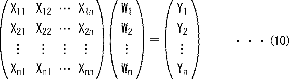
式(10)の正規方程式は、視覚障害用画像の各画素の画素値の予測値yk’の真値yk、その画素に対応する予測タップを構成する画素値xki、および予測係数Wiの関係を示す式である。式(10)の正規方程式は、例えば、掃き出し法(Gauss-Jordanの消去法)などの一般的な行列解法を用いることにより、予測係数Wiについて解くことができる。
以上により、クラスおよびボケの度合ごとの最適な予測係数Wiの学習は、式(10)の正規方程式をクラスおよびボケの度合ごとにたてて解くことにより行うことができる。
なお、画素値yは、式(3)に示した線形1次式ではなく、2次以上の高次の式によって求められるようにすることも可能である。
(スマートフォンの処理の説明)
図10は、スマートフォンの第3実施の形態の視覚障害設定処理を説明するフローチャートである。この視覚障害設定処理は、例えば、ユーザがタッチパネル21を操作することにより、視覚障害設定モードの開始を指令したとき、開始される。
図10は、スマートフォンの第3実施の形態の視覚障害設定処理を説明するフローチャートである。この視覚障害設定処理は、例えば、ユーザがタッチパネル21を操作することにより、視覚障害設定モードの開始を指令したとき、開始される。
図10のステップS51乃至S53の処理は、図5のステップS11乃至S13の処理と同様であるので、説明は省略する。
ステップS54において、視覚障害処理部120のクラスタップ抽出部121は、予測する視覚障害用画像の画素のうちの、まだ注目画素とされていない画素を注目画素に決定する。
ステップS55において、予測タップ抽出部125は、表示対象の画像から、注目画素の画素値を予測するために用いる1以上の画素値を予測タップとして取得する。そして、予測タップ抽出部125は、予測タップを生成部126に供給する。
ステップS56において、クラスタップ抽出部121は、表示対象の画像から、注目画素の画素値をクラス分類するために用いる1以上の画素値を、クラスタップとして取得する。そして、クラスタップ抽出部121は、クラスタップをクラスタップ抽出部121に供給する。
ステップS57において、クラス分類部122は、クラスタップ抽出部121から供給されるクラスタップに基づいて、注目画素の画素値をクラス分類する。クラス分類部122は、その結果得られるクラスを係数取得部124に供給する。
ステップS58において、係数取得部124は、係数記憶部123に記憶されている予測係数のうちの、クラス分類部122から供給されるクラスおよびボケ度合取得部61により取得されたボケの度合に対応する予測係数を読み出す。そして、係数取得部124は、読み出された予測係数を生成部126に供給する。
ステップS59において、生成部126は、予測タップ抽出部125から供給される予測タップと、係数取得部124から供給される予測係数とを用いて、上述した式(3)の演算を所定の予測演算として行う。これにより、生成部126は、注目画素の画素値の予測値を、視覚障害用画像の注目画素の画素値として生成し、表示制御部65に供給する。
ステップS60において、予測タップ抽出部125は、視覚障害用画像の全ての画素を注目画素としたかどうかを判定する。ステップS60で視覚障害用画像の全ての画素をまだ注目画素としていないと判定された場合、処理はステップS54に戻り、視覚障害用画像の全ての画素を注目画素とするまで、ステップS54乃至S60の処理を繰り返す。
一方、ステップS60で視覚障害用画像の全ての画素を注目画素としたと判定された場合、処理はステップS61に進む。
ステップS61乃至S63の処理は、図5のステップS16乃至S18の処理と同様であるので、説明は省略する。
以上のように、スマートフォンの第3実施の形態は、タッチパネル21に表示される画像においてユーザの視覚障害により発生するボケの度合を取得し、そのボケの度合と表示中の画像とに基づいて視覚障害用画像を生成する。従って、視覚障害用画像を生成するために多数のパラメータを取得する必要がある場合に比べて、視覚障害を持つユーザに適した画像を容易に表示させることができる。
(学習装置の構成例)
図11は、図9の係数記憶部123に記憶される予測係数を学習する学習装置140の構成例を示すブロック図である。
図11は、図9の係数記憶部123に記憶される予測係数を学習する学習装置140の構成例を示すブロック図である。
図11の学習装置140は、学習対記憶部141、クラスタップ抽出部142、クラス分類部143、予測タップ抽出部144、正規方程式生成部145、係数生成部146、係数記憶部147により構成される。
学習装置140の学習対記憶部141は、予測係数の学習に用いられる学習用の画像として、ボケの度合ごとに生徒画像と教師画像のペアを記憶する。ここでは、生徒画像として、スマートフォンの第3実施の形態において表示対象の画像とされる原画像に対応する画像が用いられる。また、教師画像として、生徒画像から生成されるボケの度合ごとの理想的な視覚障害用画像、即ち図9の生成部126によりボケの度合ごとに生成される視覚障害用画像に対応する画像が用いられる。
学習対記憶部141は、記憶しているペアごとに、そのペアの生徒画像をクラスタップ抽出部142と予測タップ抽出部144に供給し、教師画像を正規方程式生成部145に供給する。
クラスタップ抽出部142は、学習対記憶部141から供給される生徒画像とペアを構成する教師画像の各画素を順に注目画素とする。クラスタップ抽出部142は、図9のクラスタップ抽出部121と同様に、生徒画像から注目画素の画素値をクラス分類するために用いる1以上の画素値を、クラスタップとして取得し、クラス分類部143に供給する。
クラス分類部143は、図9のクラス分類部122と同様に、クラスタップ抽出部142から供給されるクラスタップに基づいて、注目画素の画素値をクラス分類し、その結果得られるクラスを正規方程式生成部145に供給する。
予測タップ抽出部144は、図9の予測タップ抽出部125と同様に、学習対記憶部141から供給される生徒画像から、注目画素の画素値を予測するために用いる1以上の画素値を予測タップとして取得し、正規方程式生成部145に供給する。
正規方程式生成部145は、学習対記憶部141から供給される教師画像の注目画素の画素値と、予測タップ抽出部144から供給される予測タップとを対象とした足し込みを、注目画素を含む教師画像に対応するボケの度合およびクラス分類部143からのクラスごとに行う。
具体的には、正規方程式生成部145は、注目画素の予測タップの各画素値を、上述した式(8)のxkiおよびxkj(i,j=1,2,・・・,n)として、クラスおよびボケの度合ごとに、上述した式(10)の左辺の行列におけるXijを演算する。また、正規方程式生成部145は、注目画素の画素値を、上述した式(9)のykとして、画素値xkiを用いて、クラスおよびボケの度合ごとに、上述した式(10)の右辺の行列におけるYiを演算する。そして、正規方程式生成部145は、全ての教師画像の全ての画素を注目画素として足し込みを行うことにより生成された、クラスおよびボケの度合ごとの上述した式(10)の正規方程式を、係数生成部146に供給する。
係数生成部146は、正規方程式生成部145から供給されるクラスおよびボケの度合ごとの正規方程式を解くことにより、クラスおよびボケの度合ごとに、最適な予測係数を求めて係数記憶部147に供給する。係数記憶部147は、係数生成部146から供給されるクラスおよびボケの度合ごとの予測係数を記憶する。このクラスおよびボケの度合ごとの予測係数は、図9の係数記憶部123に記憶される。
(学習装置の処理の説明)
図12は、図11の学習装置140の学習処理を説明するフローチャートである。
図12は、図11の学習装置140の学習処理を説明するフローチャートである。
図12のステップS71において、学習装置140の学習対記憶部141は、記憶している生徒画像と教師画像のペアのうちの、まだ読み出されていないペアを読み出す。学習対記憶部141は、読み出された生徒画像をクラスタップ抽出部142と予測タップ抽出部144に供給し、教師画像を正規方程式生成部145に供給する。
ステップS72において、クラスタップ抽出部142は、学習対記憶部141から供給される生徒画像とペアを構成する教師画像の画素のうちの、まだ注目画素とされていない画素を注目画素に決定する。
ステップS73において、クラスタップ抽出部142は、学習対記憶部141から供給される生徒画像から注目画素のクラスタップを取得し、クラス分類部143に供給する。ステップS74において、予測タップ抽出部144は、学習対記憶部141から供給される生徒画像から注目画素の予測タップを取得し、正規方程式生成部145に供給する。
ステップS75において、クラス分類部143は、クラスタップ抽出部142から供給されるクラスタップに基づいて注目画素をクラス分類し、その結果得られるクラスを正規方程式生成部145に供給する。
ステップS76において、正規方程式生成部145は、学習対記憶部141から供給される教師画像のうちの注目画素の画素値と、予測タップ抽出部144から供給される予測タップとを対象とした足し込みを、クラス分類部143からのクラスおよび注目画素を含む教師画像に対応するボケの度合ごとに行う。
ステップS77において、正規方程式生成部145は、教師画像の全ての画素を注目画素としたかどうかを判定する。ステップS77で教師画像の全ての画素をまだ注目画素としていないと判定された場合、処理はステップS72に戻り、全ての画素を注目画素とするまで、ステップS72乃至S77の処理が繰り返される。
一方、ステップS77で教師画像の全ての画素を注目画素としたと判定された場合、処理はステップS78に進む。ステップS78において、正規方程式生成部145は、学習対記憶部141に記憶されている全てのペアを読み出したかどうかを判定する。
ステップS78でまだ全てのペアを読み出していないと判定された場合、処理はステップS71に戻り、全てのペアを読み出すまで、ステップS71乃至S78の処理が繰り返される。
一方、ステップS78で全てのペアを読み出したと判定された場合、正規方程式生成部145は、ステップS76で足し込みを行うことにより生成された、クラスおよびボケの度合ごとの式(10)の正規方程式を、係数生成部146に供給する。
そして、ステップS79において、係数生成部146は、正規方程式生成部145から供給されるクラスおよびボケの度合ごとの式(10)の正規方程式を解き、クラスおよびボケの度合ごとの最適な予測係数を求める。ステップS80において、係数生成部146は、求められたクラスおよびボケの度合ごとの最適な予測係数を、係数記憶部147に供給して記憶させる。そして処理は終了する。
なお、上述した説明では、ボケの度合ごとに、生徒画像と教師画像のペアが記憶されるようにしたが、生徒画像と、その生徒画像に対応する各ボケの度合の教師画像とのペアが記憶されるようにしてもよい。即ち、生徒画像は、全てのボケの度合で共通なので、全てのボケの度合に対して1つだけ記憶されるようにしてもよい。
また、第1乃至第3実施の形態では、視覚障害設定画面40の画像41に対して視覚障害用画像が生成され、画像41として表示されたが、視覚障害設定画面40に対して視覚障害用画像が生成され、視覚障害設定画面40として表示されるようにしてもよい。この場合、ユーザの視覚障害によってBlurバー42とつまみ43に対して発生するボケも除去することができる。
<第4実施の形態>
(スマートフォンの第4実施の形態の視覚障害処理部の機能的構成例)
本開示を適用した画像処理装置としてのスマートフォンの第4実施の形態の構成は、視覚障害処理部の機能的構成を除いて、図1のスマートフォン10と同一である。従って、以下では、図1のスマートフォン10のハードウエアの各ブロックを、スマートフォンの第4実施の形態のハードウエアの各ブロックとしても用いて説明する。
(スマートフォンの第4実施の形態の視覚障害処理部の機能的構成例)
本開示を適用した画像処理装置としてのスマートフォンの第4実施の形態の構成は、視覚障害処理部の機能的構成を除いて、図1のスマートフォン10と同一である。従って、以下では、図1のスマートフォン10のハードウエアの各ブロックを、スマートフォンの第4実施の形態のハードウエアの各ブロックとしても用いて説明する。
図13は、スマートフォンの第4実施の形態の視覚障害処理部の機能的構成例を示すブロック図である。
図13に示す構成のうち、図3の構成と同じ構成には同じ符号を付してある。重複する説明については適宜省略する。
図13の視覚障害処理部160の構成は、ボケ度合取得部61の代わりに位置取得部161が設けられる点、係数取得部62および係数記憶部63の代わりに係数生成部162が設けられる点、および、表示制御部65の代わりに表示制御部163が設けられるが、図3の視覚障害処理部60の構成と異なる。位置取得部161、係数生成部162、および表示制御部163は、例えば、制御部22により実現される。
視覚障害処理部160は、ボケの度合に対応するPSFではなく、ユーザの視覚障害によるボケが発生しないときのタッチパネル21の使用位置である最適使用位置と、ユーザのタッチパネル21の通常使用位置とに基づいて、フィルタ係数を生成する。
具体的には、位置取得部161は、タッチパネル21から、ユーザがタッチパネル21を操作することにより入力した視覚障害設定モードの開始指令を表す操作信号を取得する。位置取得部161は、その操作信号に応じて、カメラ部16のフロントカメラに撮影準備動作の開始指令を供給し、撮影準備動作を開始させる。
位置取得部161は、タッチパネル21から、ユーザがタッチパネル21を操作することにより入力した撮影指令(シャッタ指令)を表す操作信号を取得する。位置取得部161は、その操作信号に応じて、カメラ部16のフロントカメラから、AF動作により得られた被写体とカメラ部16との距離を、最適使用位置を表す最適使用位置情報または通常使用位置を表す通常使用位置情報として取得する。位置取得部161は、取得された最適使用位置情報と通常使用位置情報を係数生成部162に供給する。
係数生成部162は、位置取得部161から供給される最適使用位置情報と通常使用位置情報に基づいて、ユーザの視覚障害によるボケを表すPSFを生成する。係数生成部162は、生成されたPSFに基づいて、上述した式(1)によりフィルタ係数を生成する。係数生成部162は、生成されたフィルタ係数を現在のフィルタ係数に設定し、生成部64に供給する。
表示制御部163は、通常使用位置情報を設定するための通常使用位置設定画面と最適使用位置情報を設定するための最適使用位置設定画面を、タッチパネル21に表示させる。また、表示制御部163は、生成部64から供給される視覚障害用画像をタッチパネル21に表示させる。
(通常使用位置設定画面の例)
図14は、通常使用位置設定画面の例を示す図である。
図14は、通常使用位置設定画面の例を示す図である。
図14の通常使用位置設定画面180には、撮影モードのうちの、ユーザが自分を被写体として撮影する(自分撮りする)自分撮りモード時と同一の画面が表示される。
即ち、図14に示すように、通常使用位置設定画面180には、全面に、カメラ部16のフロントカメラの仮撮影や本撮影により得られた画像181が表示される。また、画像表示領域181に重畳されて、シャッタボタン182、モードボタン183などが表示される。
シャッタボタン182は、ユーザが撮影指令を入力するときに操作するボタンである。モードボタン183は、現在のモードを表すボタンである。通常使用位置設定画面180では、モードボタン183に、視覚障害設定モードを表す目のマークが描かれている。
通常使用位置設定画面180にはまた、自分撮りモード時の画面とは異なり、例えば「通常使用位置でシャッタボタンを押して下さい。」というメッセージが記述されたメッセージ部184が、画像181に重畳される。
ユーザは、メッセージ部184に表示されたメッセージにしたがって、タッチパネル21を通常使用位置で把持し、シャッタボタン182を操作する。位置取得部161は、この操作に応じて、AF動作により測定された被写体からフロントカメラまでの距離、即ちユーザとタッチパネル21との距離を、通常使用位置情報として取得する。
(最適使用位置設定画面の例)
図15は、最適使用位置設定画面の例を示す図である。
図15は、最適使用位置設定画面の例を示す図である。
図15において、図14と同じものには同じ符号を付してある。重複する説明については適宜省略する。
図15の最適使用位置設定画面200は、メッセージ部184の代わりにメッセージ部201が設けられる点が、図14の通常使用位置設定画面180と異なる。
最適使用位置設定画面200のメッセージ部201には、例えば、「ハッキリ見える位置でシャッタボタンを押して下さい。」というメッセージが記述される。
ユーザは、メッセージ部201に表示されたメッセージにしたがって、タッチパネル21を最適使用位置で把持し、シャッタボタン182を操作する。位置取得部161は、この操作に応じて、AF動作により測定された被写体からフロントカメラまでの距離、即ちユーザとタッチパネル21との距離を、最適使用位置情報として取得する。
(PSFの生成の説明)
図16は、図13の係数生成部162によるPSFの生成を説明する図である。
図16は、図13の係数生成部162によるPSFの生成を説明する図である。
まず、空気の絶対屈折率をn1とし、目のレンズの絶対屈折率をn2とすると、スネルの法則によれば、最適使用位置について、以下の式(11)が成り立つ。従って、式(12)が成り立つ。


なお、θcは、図16に示すように、目のレンズ面と、光軸上の最適使用位置の点光源Mから目に向かう光とのなす角である。θeは、図16に示すように、目のレンズ面と、目のレンズ面から目の網膜上の像面に向かう点光源Mからの光とのなす角である。
通常使用位置についても同様に、以下の式(13)が成り立つ。

なお、θnは、図16に示すように、目のレンズ面と、光軸上の通常使用位置の点光源M´から目に向かう光とのなす角である。θpは、図16に示すように、目のレンズ面と、目のレンズ面から目の網膜上の像面に向かう点光源M´からの光とのなす角である。
式(13)を式(12)を用いて変形し、図16に示すように、目のレンズの半径をAとすると、以下の式(14)が得られる。

なお、deは、図16に示すように、目のレンズ面と網膜上の像面との距離である。dcは、最適使用位置と目のレンズとの距離であり、dnは、通常使用位置と目のレンズとの距離である。
また、点光源M´からの光により目の網膜上の像面に形成される像の半径rは、以下の式(15)により表される。

さらに、点光源M´の焦点距離fは、以下の式(16)で表される。

また、目の網膜上の像面で合焦する場合に像面に形成される半径rの像に対応する通常使用位置の光源の半径rd、即ち通常使用位置で視覚障害により発生するボケは、焦点距離fを用いて、以下の式(17)で表される。

式(17)に式(14)乃至(16)を代入し、目のレンズの半径A、目のレンズと網膜上の像面の距離deとして、所定値を代入すると、半径rdを求める式は、距離dcと距離dnを変数とする式になる。
従って、係数生成部162は、まず、この式の距離dcに最適使用位置情報が表す距離を代入し、距離dnに通常使用位置情報が表す距離を代入することにより、通常使用位置でユーザの視覚障害により発生するボケの半径rdを求める。次に、係数生成部162は、絶対半径である半径rdをタッチパネル21の画素サイズで除算することにより、画素数rpに変換する。
そして、係数生成部162は、画素数rpに基づいて、Gauss関数に近似するPSFを生成する。具体的には、Gauss関数の成分の99.7%は3σ以内となるため、係数生成部162は、3σ=rpとなるようにPSFを生成する。なお、PSFの平均は0とする。
(スマートフォンの処理の説明)
図17は、スマートフォンの第4実施の形態の視覚障害設定処理を説明するフローチャートである。この視覚障害設定処理は、例えば、ユーザがタッチパネル21を操作することにより、視覚障害設定モードの開始を指令したとき、開始される。
図17は、スマートフォンの第4実施の形態の視覚障害設定処理を説明するフローチャートである。この視覚障害設定処理は、例えば、ユーザがタッチパネル21を操作することにより、視覚障害設定モードの開始を指令したとき、開始される。
図17のステップS101において、位置取得部161は、カメラ部16のフロントカメラに撮影準備動作の開始指令を供給し、撮影準備動作を開始させる。ステップS102において、表示制御部163は、通常使用位置設定画面180を表示させる。
ステップS103において、位置取得部161は、ユーザによりシャッタボタン182が操作されたかどうかを判定する。位置取得部161は、タッチパネル21から、ユーザがシャッタボタン182を操作することにより入力した撮影指令を表す操作信号を取得していない場合、ステップS103で、シャッタボタン182がまだ操作されていないと判定する。そして、位置取得部161は、その操作信号を取得するまで、待機する。
一方、位置取得部161は、タッチパネル21から、ユーザがシャッタボタン182を操作することにより入力した撮影指令を表す操作信号を取得した場合、ステップS103でシャッタボタン182が操作されたと判定する。そして、表示制御部163は、通常使用位置設定画面180のうちのメッセージ部184を削除し、処理をステップS104に進める。
ステップS104において、位置取得部161は、カメラ部16のフロントカメラから、撮影準備動作のうちのAF動作により得られた被写体とカメラ部16との距離を、通常使用位置情報として取得する。位置取得部161は、取得された通常使用位置情報を係数生成部162に供給する。
ステップS105において、表示制御部163は、最適使用位置設定画面200を、メッセージ部184が削除された通常使用位置設定画面180に代えてタッチパネル21に表示させる。ステップS106において、位置取得部161は、ステップS103の処理と同様に、ユーザによりシャッタボタン182が操作されたかどうかを判定する。
ステップS103でシャッタボタン182がまだ操作されていないと判定された場合、位置取得部161は、シャッタボタン182が操作されるまで待機する。一方、ステップS103でシャッタボタン182が操作されたと判定された場合、表示制御部163は、最適使用位置設定画面200のうちのメッセージ部201を削除し、処理をステップS107に進める。
ステップS107において、位置取得部161は、カメラ部16のフロントカメラから、撮影準備動作のうちのAF動作により得られた被写体とカメラ部16との距離を、最適使用位置情報として取得する。位置取得部161は、取得された最適使用位置情報を係数生成部162に供給する。
ステップS108において、係数生成部162は、位置取得部161から供給される最適使用位置情報と通常使用位置情報に基づいて、ユーザの視覚障害によるボケを表すPSFを生成する。
ステップS109において、係数生成部162は、PSFに基づいて、上述した式(1)によりフィルタ係数を生成する。係数生成部162は、生成されたフィルタ係数を現在のフィルタ係数に設定し、生成部64に供給する。
ステップS110において、生成部64は、係数生成部162から供給されるフィルタ係数を用いて、表示中の画像181に対してウィナーフィルタ処理を行うことにより、視覚障害用画像を生成する。生成部64は、生成された視覚障害用画像を表示制御部163に供給する。
ステップS111において、表示制御部163は、生成部64により生成された視覚障害用画像をタッチパネル21に供給し、最適使用位置設定画面200の画像181として表示させる。
ステップS112において、制御部22は、視覚障害設定処理を終了するかどうか、例えば、ユーザがタッチパネル21を操作することにより視覚障害設定モードの終了を指令したかどうかを判定する。
ステップS112で視覚障害設定処理を終了しないと判定された場合、処理はステップS102に戻り、表示制御部163は、メッセージ部201が削除された最適使用位置設定画面200に代えて、通常使用位置設定画面180をタッチパネル21に表示させる。そして、ステップS103乃至S112の処理が繰り返される。
一方、ステップS112で視覚障害設定処理を終了すると判定された場合、ステップS113において、位置取得部161は、カメラ部16のフロントカメラに撮影準備動作の終了指令を供給し、撮影準備動作を終了させる。
ステップS114において、表示制御部163は、メッセージ部201が削除された最適使用位置設定画面200の表示を終了させ、処理を終了する。
なお、第4実施の形態では、スマートフォンがPSFを生成したが、外部のサーバがPSFを生成するようにしてもよい。この場合、スマートフォンは、最適使用位置情報と通常使用位置情報を外部のサーバに送信し、外部のサーバから、その最適使用位置情報と通常使用位置情報に基づいて生成されたPSFを受信する。
また、スマートフォンは、最適使用位置情報と通常使用位置情報を外部のサーバに送信し、外部のサーバから、その最適使用位置情報と通常使用位置情報に基づいて生成されたPSFに基づくフィルタ係数を受信するようにしてもよい。
さらに、通常使用位置情報は、ユーザにより入力されるのではなく、予め決められていてもよい。また、通常使用位置設定画面と最適使用位置設定画面の表示順は、図17の場合のように、通常使用位置設定画面、最適使用位置設定画面の順であってもよいし、最適使用位置設定画面、通常使用位置設定画面の順であってもよい。
以上のように、スマートフォンの第4実施の形態は、最適使用位置を取得し、その最適使用位置、通常使用位置、および表示対象の画像に基づいて視覚障害用画像を表示する。従って、視覚障害用画像を生成するために多数のパラメータを取得する必要がある場合に比べて、視覚障害を持つユーザに適した画像を容易に表示させることができる。
なお、本明細書において、プログラム記録媒体に格納されるプログラムを記述するステップは、記載された順序に沿って時系列的に行われる処理はもちろん、必ずしも時系列的に処理されなくとも、並列的あるいは個別に実行される処理をも含むものである。
また、本明細書において、システムとは、複数の構成要素(装置、モジュール(部品)等)の集合を意味し、すべての構成要素が同一筐体中にあるか否かは問わない。したがって、別個の筐体に収納され、ネットワークを介して接続されている複数の装置、及び、1つの筐体の中に複数のモジュールが収納されている1つの装置は、いずれも、システムである。
さらに、本明細書に記載された効果はあくまで例示であって限定されるものではなく、他の効果があってもよい。
また、本開示の実施の形態は、上述した実施の形態に限定されるものではなく、本開示の要旨を逸脱しない範囲において種々の変更が可能である。
例えば、本開示は、1つの機能をネットワークを介して複数の装置で分担、共同して処理するクラウドコンピューティングの構成をとることができる。
また、上述のフローチャートで説明した各ステップは、1つの装置で実行する他、複数の装置で分担して実行することができる。
さらに、1つのステップに複数の処理が含まれる場合には、その1つのステップに含まれる複数の処理は、1つの装置で実行する他、複数の装置で分担して実行することができる。
本開示は、以下のような構成もとることができる。
(1)
ユーザの視覚障害によるボケが発生しないときの表示装置の使用位置である最適使用位置を取得する位置取得部と、
前記位置取得部により取得された前記最適使用位置、前記表示装置の通常使用位置、および表示対象の画像に基づいて、前記通常使用位置の前記表示装置において前記ボケが発生しない視覚障害用画像を前記表示装置に表示させる表示制御部と
を備える画像処理装置。
(2)
前記位置取得部は、前記通常使用位置を取得し、
前記表示制御部は、前記位置取得部により取得された前記最適使用位置および前記通常使用位置と、前記表示対象の画像とに基づいて、前記表示装置に前記視覚障害用画像を表示させる
ように構成された
前記(1)に記載の画像処理装置。
(3)
前記最適使用位置と前記通常使用位置に基づいて生成されるフィルタ係数を用いて、前記表示対象の画像に対してフィルタ処理を行うことにより、前記視覚障害用画像を生成する生成部と、
前記表示制御部は、前記生成部により生成された前記視覚障害用画像を前記表示装置に表示させる
ように構成された
前記(1)または(2)に記載の画像処理装置。
(4)
前記最適使用位置と前記通常使用位置に基づいて前記ボケを表す関数を生成し、前記関数に基づいて、前記フィルタ係数を生成する係数生成部
をさらに備え、
前記生成部は、前記係数生成部により生成された前記フィルタ係数を用いて、前記表示対象の画像に対してフィルタ処理を行う
ように構成された
前記(3)に記載の画像処理装置。
(5)
前記位置取得部は、AF動作により、前記最適使用位置を取得する
ように構成された
前記(1)乃至(4)に記載の画像処理装置。
(6)
画像処理装置が、
ユーザの視覚障害によるボケが発生しないときの表示装置の使用位置である最適使用位置を取得する位置取得ステップと、
前記位置取得ステップの処理により取得された前記最適使用位置、前記表示装置の通常使用位置、および表示対象の画像に基づいて、前記通常使用位置の前記表示装置において前記ボケが発生しない視覚障害用画像を前記表示装置に表示させる表示制御ステップと
を含む画像処理方法。
(7)
コンピュータを、
ユーザの視覚障害によるボケが発生しないときの表示装置の使用位置である最適使用位置を取得する位置取得部と、
前記位置取得部により取得された前記最適使用位置、前記表示装置の通常使用位置、および表示対象の画像に基づいて、前記通常使用位置の前記表示装置において前記ボケが発生しない視覚障害用画像を前記表示装置に表示させる表示制御部と
して機能させるためのプログラム。
(8)
表示装置に表示される画像においてユーザの視覚障害により発生するボケの度合を取得するボケ度合取得部と、
前記ボケ度合取得部により取得された前記ボケの度合と、表示対象の画像とに基づいて、前記ボケが発生しない視覚障害用画像を前記表示装置に表示させる表示制御部と
を備える画像処理装置。
(9)
前記ボケ度合取得部により取得された前記ボケの度合に対応するフィルタ係数を用いて、前記表示対象の画像に対してフィルタ処理を行うことにより、前記視覚障害用画像を生成する生成部と、
前記表示制御部は、前記生成部により生成された前記視覚障害用画像を前記表示装置に表示させる
ように構成された
前記(8)に記載の画像処理装置。
(10)
前記ボケ度合取得部により取得された前記ボケの度合に対応する前記ボケを表す関数に基づいて、前記フィルタ係数を生成する係数生成部
をさらに備え、
前記生成部は、前記係数生成部により生成された前記フィルタ係数を用いて、前記表示対象の画像に対してフィルタ処理を行う
前記(9)に記載の画像処理装置。
(11)
前記フィルタ係数は、前記ボケの度合ごとに、前記視覚障害用画像に対応する教師画像と前記表示対象の画像に対応する生徒画像とを用いて、前記教師画像の各画素の画素値、その画素に対応する前記生徒画像の画素の画素値、および予測係数の関係を示す式を解くことにより学習された前記予測係数である
ように構成された
前記(9)に記載の画像処理装置。
(12)
画像処理装置が、
表示装置に表示される画像においてユーザの視覚障害により発生するボケの度合を取得するボケ度合取得ステップと、
前記ボケ度合取得ステップの処理により取得された前記ボケの度合と、表示対象の画像とに基づいて、前記ボケが発生しない視覚障害用画像を前記表示装置に表示させる表示制御ステップと
を含む画像処理方法。
(13)
コンピュータを、
表示装置に表示される画像においてユーザの視覚障害により発生するボケの度合を取得するボケ度合取得部と、
前記ボケ度合取得部により取得された前記ボケの度合と、表示対象の画像とに基づいて、前記ボケが発生しない視覚障害用画像を前記表示装置に表示させる表示制御部と
して機能させるためのプログラム。
ユーザの視覚障害によるボケが発生しないときの表示装置の使用位置である最適使用位置を取得する位置取得部と、
前記位置取得部により取得された前記最適使用位置、前記表示装置の通常使用位置、および表示対象の画像に基づいて、前記通常使用位置の前記表示装置において前記ボケが発生しない視覚障害用画像を前記表示装置に表示させる表示制御部と
を備える画像処理装置。
(2)
前記位置取得部は、前記通常使用位置を取得し、
前記表示制御部は、前記位置取得部により取得された前記最適使用位置および前記通常使用位置と、前記表示対象の画像とに基づいて、前記表示装置に前記視覚障害用画像を表示させる
ように構成された
前記(1)に記載の画像処理装置。
(3)
前記最適使用位置と前記通常使用位置に基づいて生成されるフィルタ係数を用いて、前記表示対象の画像に対してフィルタ処理を行うことにより、前記視覚障害用画像を生成する生成部と、
前記表示制御部は、前記生成部により生成された前記視覚障害用画像を前記表示装置に表示させる
ように構成された
前記(1)または(2)に記載の画像処理装置。
(4)
前記最適使用位置と前記通常使用位置に基づいて前記ボケを表す関数を生成し、前記関数に基づいて、前記フィルタ係数を生成する係数生成部
をさらに備え、
前記生成部は、前記係数生成部により生成された前記フィルタ係数を用いて、前記表示対象の画像に対してフィルタ処理を行う
ように構成された
前記(3)に記載の画像処理装置。
(5)
前記位置取得部は、AF動作により、前記最適使用位置を取得する
ように構成された
前記(1)乃至(4)に記載の画像処理装置。
(6)
画像処理装置が、
ユーザの視覚障害によるボケが発生しないときの表示装置の使用位置である最適使用位置を取得する位置取得ステップと、
前記位置取得ステップの処理により取得された前記最適使用位置、前記表示装置の通常使用位置、および表示対象の画像に基づいて、前記通常使用位置の前記表示装置において前記ボケが発生しない視覚障害用画像を前記表示装置に表示させる表示制御ステップと
を含む画像処理方法。
(7)
コンピュータを、
ユーザの視覚障害によるボケが発生しないときの表示装置の使用位置である最適使用位置を取得する位置取得部と、
前記位置取得部により取得された前記最適使用位置、前記表示装置の通常使用位置、および表示対象の画像に基づいて、前記通常使用位置の前記表示装置において前記ボケが発生しない視覚障害用画像を前記表示装置に表示させる表示制御部と
して機能させるためのプログラム。
(8)
表示装置に表示される画像においてユーザの視覚障害により発生するボケの度合を取得するボケ度合取得部と、
前記ボケ度合取得部により取得された前記ボケの度合と、表示対象の画像とに基づいて、前記ボケが発生しない視覚障害用画像を前記表示装置に表示させる表示制御部と
を備える画像処理装置。
(9)
前記ボケ度合取得部により取得された前記ボケの度合に対応するフィルタ係数を用いて、前記表示対象の画像に対してフィルタ処理を行うことにより、前記視覚障害用画像を生成する生成部と、
前記表示制御部は、前記生成部により生成された前記視覚障害用画像を前記表示装置に表示させる
ように構成された
前記(8)に記載の画像処理装置。
(10)
前記ボケ度合取得部により取得された前記ボケの度合に対応する前記ボケを表す関数に基づいて、前記フィルタ係数を生成する係数生成部
をさらに備え、
前記生成部は、前記係数生成部により生成された前記フィルタ係数を用いて、前記表示対象の画像に対してフィルタ処理を行う
前記(9)に記載の画像処理装置。
(11)
前記フィルタ係数は、前記ボケの度合ごとに、前記視覚障害用画像に対応する教師画像と前記表示対象の画像に対応する生徒画像とを用いて、前記教師画像の各画素の画素値、その画素に対応する前記生徒画像の画素の画素値、および予測係数の関係を示す式を解くことにより学習された前記予測係数である
ように構成された
前記(9)に記載の画像処理装置。
(12)
画像処理装置が、
表示装置に表示される画像においてユーザの視覚障害により発生するボケの度合を取得するボケ度合取得ステップと、
前記ボケ度合取得ステップの処理により取得された前記ボケの度合と、表示対象の画像とに基づいて、前記ボケが発生しない視覚障害用画像を前記表示装置に表示させる表示制御ステップと
を含む画像処理方法。
(13)
コンピュータを、
表示装置に表示される画像においてユーザの視覚障害により発生するボケの度合を取得するボケ度合取得部と、
前記ボケ度合取得部により取得された前記ボケの度合と、表示対象の画像とに基づいて、前記ボケが発生しない視覚障害用画像を前記表示装置に表示させる表示制御部と
して機能させるためのプログラム。
10 スマートフォン, 21 タッチパネル, 61 ボケ度合取得部, 64 生成部, 65 表示制御部, 103 係数生成部, 126 生成部, 161 位置取得部, 162 係数生成部, 163 表示制御部
Claims (13)
- ユーザの視覚障害によるボケが発生しないときの表示装置の使用位置である最適使用位置を取得する位置取得部と、
前記位置取得部により取得された前記最適使用位置、前記表示装置の通常使用位置、および表示対象の画像に基づいて、前記通常使用位置の前記表示装置において前記ボケが発生しない視覚障害用画像を前記表示装置に表示させる表示制御部と
を備える画像処理装置。 - 前記位置取得部は、前記通常使用位置を取得し、
前記表示制御部は、前記位置取得部により取得された前記最適使用位置および前記通常使用位置と、前記表示対象の画像とに基づいて、前記表示装置に前記視覚障害用画像を表示させる
ように構成された
請求項1に記載の画像処理装置。 - 前記最適使用位置と前記通常使用位置に基づいて生成されるフィルタ係数を用いて、前記表示対象の画像に対してフィルタ処理を行うことにより、前記視覚障害用画像を生成する生成部と、
前記表示制御部は、前記生成部により生成された前記視覚障害用画像を前記表示装置に表示させる
ように構成された
請求項1に記載の画像処理装置。 - 前記最適使用位置と前記通常使用位置に基づいて前記ボケを表す関数を生成し、前記関数に基づいて、前記フィルタ係数を生成する係数生成部
をさらに備え、
前記生成部は、前記係数生成部により生成された前記フィルタ係数を用いて、前記表示対象の画像に対してフィルタ処理を行う
ように構成された
請求項3に記載の画像処理装置。 - 前記位置取得部は、AF動作により、前記最適使用位置を取得する
ように構成された
請求項1に記載の画像処理装置。 - 画像処理装置が、
ユーザの視覚障害によるボケが発生しないときの表示装置の使用位置である最適使用位置を取得する位置取得ステップと、
前記位置取得ステップの処理により取得された前記最適使用位置、前記表示装置の通常使用位置、および表示対象の画像に基づいて、前記通常使用位置の前記表示装置において前記ボケが発生しない視覚障害用画像を前記表示装置に表示させる表示制御ステップと
を含む画像処理方法。 - コンピュータを、
ユーザの視覚障害によるボケが発生しないときの表示装置の使用位置である最適使用位置を取得する位置取得部と、
前記位置取得部により取得された前記最適使用位置、前記表示装置の通常使用位置、および表示対象の画像に基づいて、前記通常使用位置の前記表示装置において前記ボケが発生しない視覚障害用画像を前記表示装置に表示させる表示制御部と
して機能させるためのプログラム。 - 表示装置に表示される画像においてユーザの視覚障害により発生するボケの度合を取得するボケ度合取得部と、
前記ボケ度合取得部により取得された前記ボケの度合と、表示対象の画像とに基づいて、前記ボケが発生しない視覚障害用画像を前記表示装置に表示させる表示制御部と
を備える画像処理装置。 - 前記ボケ度合取得部により取得された前記ボケの度合に対応するフィルタ係数を用いて、前記表示対象の画像に対してフィルタ処理を行うことにより、前記視覚障害用画像を生成する生成部と、
前記表示制御部は、前記生成部により生成された前記視覚障害用画像を前記表示装置に表示させる
ように構成された
請求項8に記載の画像処理装置。 - 前記ボケ度合取得部により取得された前記ボケの度合に対応する前記ボケを表す関数に基づいて、前記フィルタ係数を生成する係数生成部
をさらに備え、
前記生成部は、前記係数生成部により生成された前記フィルタ係数を用いて、前記表示対象の画像に対してフィルタ処理を行う
請求項9に記載の画像処理装置。 - 前記フィルタ係数は、前記ボケの度合ごとに、前記視覚障害用画像に対応する教師画像と前記表示対象の画像に対応する生徒画像とを用いて、前記教師画像の各画素の画素値、その画素に対応する前記生徒画像の画素の画素値、および予測係数の関係を示す式を解くことにより学習された前記予測係数である
ように構成された
請求項9に記載の画像処理装置。 - 画像処理装置が、
表示装置に表示される画像においてユーザの視覚障害により発生するボケの度合を取得するボケ度合取得ステップと、
前記ボケ度合取得ステップの処理により取得された前記ボケの度合と、表示対象の画像とに基づいて、前記ボケが発生しない視覚障害用画像を前記表示装置に表示させる表示制御ステップと
を含む画像処理方法。 - コンピュータを、
表示装置に表示される画像においてユーザの視覚障害により発生するボケの度合を取得するボケ度合取得部と、
前記ボケ度合取得部により取得された前記ボケの度合と、表示対象の画像とに基づいて、前記ボケが発生しない視覚障害用画像を前記表示装置に表示させる表示制御部と
して機能させるためのプログラム。
Applications Claiming Priority (2)
| Application Number | Priority Date | Filing Date | Title |
|---|---|---|---|
| JP2014-250166 | 2014-12-10 | ||
| JP2014250166 | 2014-12-10 |
Publications (1)
| Publication Number | Publication Date |
|---|---|
| WO2016093071A1 true WO2016093071A1 (ja) | 2016-06-16 |
Family
ID=56107261
Family Applications (1)
| Application Number | Title | Priority Date | Filing Date |
|---|---|---|---|
| PCT/JP2015/083243 Ceased WO2016093071A1 (ja) | 2014-12-10 | 2015-11-26 | 画像処理装置、画像処理方法、およびプログラム |
Country Status (1)
| Country | Link |
|---|---|
| WO (1) | WO2016093071A1 (ja) |
Cited By (1)
| Publication number | Priority date | Publication date | Assignee | Title |
|---|---|---|---|---|
| DE102023132267A1 (de) * | 2023-11-20 | 2025-05-22 | Schwind Eye-Tech-Solutions Gmbh | Verfahren zum Kompensieren einer Fehlsichtigkeit eines Benutzers für eine Anzeigevorrichtung, Anzeigevorrichtung, Computerprogramm und computerlesbares Medium |
Citations (5)
| Publication number | Priority date | Publication date | Assignee | Title |
|---|---|---|---|---|
| JPH0997333A (ja) * | 1995-07-25 | 1997-04-08 | Toyota Central Res & Dev Lab Inc | 画像処理装置 |
| JP2011095839A (ja) * | 2009-10-27 | 2011-05-12 | Olympus Corp | 補正画像データ生成方法及び表示装置 |
| JP2012063589A (ja) * | 2010-09-16 | 2012-03-29 | Nippon Hoso Kyokai <Nhk> | 視度補正装置 |
| JP2013528115A (ja) * | 2010-06-11 | 2013-07-08 | バック イン フォーカス | 観察者の視覚障害を補正するための表示を表現するシステム、方法、およびそのプログラムを格納している記憶媒体 |
| JP2015094788A (ja) * | 2013-11-08 | 2015-05-18 | 富士通株式会社 | 表示装置および表示制御プログラム |
-
2015
- 2015-11-26 WO PCT/JP2015/083243 patent/WO2016093071A1/ja not_active Ceased
Patent Citations (5)
| Publication number | Priority date | Publication date | Assignee | Title |
|---|---|---|---|---|
| JPH0997333A (ja) * | 1995-07-25 | 1997-04-08 | Toyota Central Res & Dev Lab Inc | 画像処理装置 |
| JP2011095839A (ja) * | 2009-10-27 | 2011-05-12 | Olympus Corp | 補正画像データ生成方法及び表示装置 |
| JP2013528115A (ja) * | 2010-06-11 | 2013-07-08 | バック イン フォーカス | 観察者の視覚障害を補正するための表示を表現するシステム、方法、およびそのプログラムを格納している記憶媒体 |
| JP2012063589A (ja) * | 2010-09-16 | 2012-03-29 | Nippon Hoso Kyokai <Nhk> | 視度補正装置 |
| JP2015094788A (ja) * | 2013-11-08 | 2015-05-18 | 富士通株式会社 | 表示装置および表示制御プログラム |
Non-Patent Citations (1)
| Title |
|---|
| MIDORI AOKI ET AL.: "Jizen Boke Fukugen ni Motozuku Shiryoku Kaso Kyosei Display", SSII2014 DAI 20 KAI SYMPOSIUM ON SENSING VIA IMAGE INFORMATION KOEN RONBUNSHU, 11 June 2014 (2014-06-11), pages 223-1 - 223-7 * |
Cited By (1)
| Publication number | Priority date | Publication date | Assignee | Title |
|---|---|---|---|---|
| DE102023132267A1 (de) * | 2023-11-20 | 2025-05-22 | Schwind Eye-Tech-Solutions Gmbh | Verfahren zum Kompensieren einer Fehlsichtigkeit eines Benutzers für eine Anzeigevorrichtung, Anzeigevorrichtung, Computerprogramm und computerlesbares Medium |
Similar Documents
| Publication | Publication Date | Title |
|---|---|---|
| JP7186672B2 (ja) | マルチスコピック雑音削減およびハイ・ダイナミック・レンジのためのシステムおよび方法 | |
| CN113992861B (zh) | 一种图像处理方法及图像处理装置 | |
| US11450013B2 (en) | Method and apparatus for obtaining sample image set | |
| JP2021197144A (ja) | 画像ノイズ除去モデルの訓練方法、画像ノイズ除去方法、装置及び媒体 | |
| CN111275653A (zh) | 图像去噪方法及装置 | |
| CN106651808B (zh) | 一种鱼眼图转换方法及装置 | |
| CN110827219A (zh) | 图像处理模型的训练方法、装置及介质 | |
| CN110223245B (zh) | 基于深度神经网络的模糊图片清晰化处理方法及系统 | |
| CN112750092B (zh) | 训练数据获取方法、像质增强模型与方法及电子设备 | |
| CN110533618A (zh) | 一种镜头畸变矫正的方法和照相装置 | |
| CN108074241B (zh) | 目标图像的质量评分方法、装置、终端及存储介质 | |
| CN112288664B (zh) | 高动态范围图像的融合方法、装置和电子设备 | |
| CN112085775A (zh) | 图像处理的方法、装置、终端和存储介质 | |
| JP2021033571A (ja) | 情報処理装置、制御方法およびプログラム | |
| CN113891004B (zh) | 图像处理方法、装置、设备及存储介质 | |
| JP2016220171A (ja) | 拡張現実対象認識装置 | |
| WO2016093071A1 (ja) | 画像処理装置、画像処理方法、およびプログラム | |
| DE112013004760B4 (de) | Bilderfassungsvorrichtung und Bildverarbeitungsverfahren | |
| CN106954060B (zh) | 一种面向智能手机的立体视频生成方法及辅助拍摄装置 | |
| CN115937044A (zh) | 图像处理方法、图像处理装置、存储介质与电子设备 | |
| CN108848366B (zh) | 基于3d摄像机的信息获取装置及方法 | |
| CN111242998B (zh) | 图像融合方法和装置 | |
| JP2013192152A (ja) | 撮像装置、撮像システムおよび画像処理方法 | |
| KR102268337B1 (ko) | Ar 기반 퍼포먼스 영상 관람 시스템 및 이를 이용한 퍼포먼스 영상 제공 방법 | |
| CN117036177A (zh) | 图像恢复模型的确定方法、图像恢复方法及装置 |
Legal Events
| Date | Code | Title | Description |
|---|---|---|---|
| 121 | Ep: the epo has been informed by wipo that ep was designated in this application |
Ref document number: 15867573 Country of ref document: EP Kind code of ref document: A1 |
|
| NENP | Non-entry into the national phase |
Ref country code: DE |
|
| 122 | Ep: pct application non-entry in european phase |
Ref document number: 15867573 Country of ref document: EP Kind code of ref document: A1 |
|
| NENP | Non-entry into the national phase |
Ref country code: JP |