WO2016092792A1 - Heater device - Google Patents
Heater device Download PDFInfo
- Publication number
- WO2016092792A1 WO2016092792A1 PCT/JP2015/006036 JP2015006036W WO2016092792A1 WO 2016092792 A1 WO2016092792 A1 WO 2016092792A1 JP 2015006036 W JP2015006036 W JP 2015006036W WO 2016092792 A1 WO2016092792 A1 WO 2016092792A1
- Authority
- WO
- WIPO (PCT)
- Prior art keywords
- heater
- temperature
- suppression
- moisture
- control unit
- Prior art date
Links
Images

Classifications
-
- B—PERFORMING OPERATIONS; TRANSPORTING
- B60—VEHICLES IN GENERAL
- B60H—ARRANGEMENTS OF HEATING, COOLING, VENTILATING OR OTHER AIR-TREATING DEVICES SPECIALLY ADAPTED FOR PASSENGER OR GOODS SPACES OF VEHICLES
- B60H1/00—Heating, cooling or ventilating [HVAC] devices
- B60H1/22—Heating, cooling or ventilating [HVAC] devices the heat being derived otherwise than from the propulsion plant
-
- B—PERFORMING OPERATIONS; TRANSPORTING
- B60—VEHICLES IN GENERAL
- B60H—ARRANGEMENTS OF HEATING, COOLING, VENTILATING OR OTHER AIR-TREATING DEVICES SPECIALLY ADAPTED FOR PASSENGER OR GOODS SPACES OF VEHICLES
- B60H1/00—Heating, cooling or ventilating [HVAC] devices
- B60H1/00271—HVAC devices specially adapted for particular vehicle parts or components and being connected to the vehicle HVAC unit
- B60H1/00292—HVAC devices specially adapted for particular vehicle parts or components and being connected to the vehicle HVAC unit for steering wheels
-
- B—PERFORMING OPERATIONS; TRANSPORTING
- B60—VEHICLES IN GENERAL
- B60H—ARRANGEMENTS OF HEATING, COOLING, VENTILATING OR OTHER AIR-TREATING DEVICES SPECIALLY ADAPTED FOR PASSENGER OR GOODS SPACES OF VEHICLES
- B60H1/00—Heating, cooling or ventilating [HVAC] devices
- B60H1/22—Heating, cooling or ventilating [HVAC] devices the heat being derived otherwise than from the propulsion plant
- B60H1/2215—Heating, cooling or ventilating [HVAC] devices the heat being derived otherwise than from the propulsion plant the heat being derived from electric heaters
- B60H1/2226—Electric heaters using radiation
-
- B—PERFORMING OPERATIONS; TRANSPORTING
- B60—VEHICLES IN GENERAL
- B60H—ARRANGEMENTS OF HEATING, COOLING, VENTILATING OR OTHER AIR-TREATING DEVICES SPECIALLY ADAPTED FOR PASSENGER OR GOODS SPACES OF VEHICLES
- B60H3/00—Other air-treating devices
- B60H3/02—Moistening ; Devices influencing humidity levels, i.e. humidity control
- B60H3/024—Moistening ; Devices influencing humidity levels, i.e. humidity control for only dehumidifying the air
-
- H—ELECTRICITY
- H05—ELECTRIC TECHNIQUES NOT OTHERWISE PROVIDED FOR
- H05B—ELECTRIC HEATING; ELECTRIC LIGHT SOURCES NOT OTHERWISE PROVIDED FOR; CIRCUIT ARRANGEMENTS FOR ELECTRIC LIGHT SOURCES, IN GENERAL
- H05B1/00—Details of electric heating devices
- H05B1/02—Automatic switching arrangements specially adapted to apparatus ; Control of heating devices
- H05B1/0227—Applications
- H05B1/023—Industrial applications
- H05B1/0236—Industrial applications for vehicles
-
- H—ELECTRICITY
- H05—ELECTRIC TECHNIQUES NOT OTHERWISE PROVIDED FOR
- H05B—ELECTRIC HEATING; ELECTRIC LIGHT SOURCES NOT OTHERWISE PROVIDED FOR; CIRCUIT ARRANGEMENTS FOR ELECTRIC LIGHT SOURCES, IN GENERAL
- H05B3/00—Ohmic-resistance heating
-
- H—ELECTRICITY
- H05—ELECTRIC TECHNIQUES NOT OTHERWISE PROVIDED FOR
- H05B—ELECTRIC HEATING; ELECTRIC LIGHT SOURCES NOT OTHERWISE PROVIDED FOR; CIRCUIT ARRANGEMENTS FOR ELECTRIC LIGHT SOURCES, IN GENERAL
- H05B3/00—Ohmic-resistance heating
- H05B3/20—Heating elements having extended surface area substantially in a two-dimensional plane, e.g. plate-heater
- H05B3/22—Heating elements having extended surface area substantially in a two-dimensional plane, e.g. plate-heater non-flexible
- H05B3/26—Heating elements having extended surface area substantially in a two-dimensional plane, e.g. plate-heater non-flexible heating conductor mounted on insulating base
- H05B3/267—Heating elements having extended surface area substantially in a two-dimensional plane, e.g. plate-heater non-flexible heating conductor mounted on insulating base the insulating base being an organic material, e.g. plastic
-
- H—ELECTRICITY
- H05—ELECTRIC TECHNIQUES NOT OTHERWISE PROVIDED FOR
- H05B—ELECTRIC HEATING; ELECTRIC LIGHT SOURCES NOT OTHERWISE PROVIDED FOR; CIRCUIT ARRANGEMENTS FOR ELECTRIC LIGHT SOURCES, IN GENERAL
- H05B3/00—Ohmic-resistance heating
- H05B3/20—Heating elements having extended surface area substantially in a two-dimensional plane, e.g. plate-heater
- H05B3/34—Heating elements having extended surface area substantially in a two-dimensional plane, e.g. plate-heater flexible, e.g. heating nets or webs
-
- B—PERFORMING OPERATIONS; TRANSPORTING
- B60—VEHICLES IN GENERAL
- B60H—ARRANGEMENTS OF HEATING, COOLING, VENTILATING OR OTHER AIR-TREATING DEVICES SPECIALLY ADAPTED FOR PASSENGER OR GOODS SPACES OF VEHICLES
- B60H1/00—Heating, cooling or ventilating [HVAC] devices
- B60H1/22—Heating, cooling or ventilating [HVAC] devices the heat being derived otherwise than from the propulsion plant
- B60H2001/2228—Heating, cooling or ventilating [HVAC] devices the heat being derived otherwise than from the propulsion plant controlling the operation of heaters
-
- B—PERFORMING OPERATIONS; TRANSPORTING
- B60—VEHICLES IN GENERAL
- B60H—ARRANGEMENTS OF HEATING, COOLING, VENTILATING OR OTHER AIR-TREATING DEVICES SPECIALLY ADAPTED FOR PASSENGER OR GOODS SPACES OF VEHICLES
- B60H1/00—Heating, cooling or ventilating [HVAC] devices
- B60H1/22—Heating, cooling or ventilating [HVAC] devices the heat being derived otherwise than from the propulsion plant
- B60H2001/2246—Heating, cooling or ventilating [HVAC] devices the heat being derived otherwise than from the propulsion plant obtaining information from a variable, e.g. by means of a sensor
-
- H—ELECTRICITY
- H05—ELECTRIC TECHNIQUES NOT OTHERWISE PROVIDED FOR
- H05B—ELECTRIC HEATING; ELECTRIC LIGHT SOURCES NOT OTHERWISE PROVIDED FOR; CIRCUIT ARRANGEMENTS FOR ELECTRIC LIGHT SOURCES, IN GENERAL
- H05B2203/00—Aspects relating to Ohmic resistive heating covered by group H05B3/00
- H05B2203/002—Heaters using a particular layout for the resistive material or resistive elements
- H05B2203/003—Heaters using a particular layout for the resistive material or resistive elements using serpentine layout
-
- H—ELECTRICITY
- H05—ELECTRIC TECHNIQUES NOT OTHERWISE PROVIDED FOR
- H05B—ELECTRIC HEATING; ELECTRIC LIGHT SOURCES NOT OTHERWISE PROVIDED FOR; CIRCUIT ARRANGEMENTS FOR ELECTRIC LIGHT SOURCES, IN GENERAL
- H05B2203/00—Aspects relating to Ohmic resistive heating covered by group H05B3/00
- H05B2203/013—Heaters using resistive films or coatings
Definitions
- the disclosure in this specification relates to an indoor heater device installed indoors.
- Patent Documents 1 to 5 describe a heater device that is provided indoors and provides a warm feeling to a person.
- the heater device can also be called a heater device for heating.
- the heater device can also be referred to as an electric heater device.
- One form of the heater device is also called a radiation heater device that gives a person a warm feeling by radiation.
- One application of the heater device is for vehicles.
- the heater device described in Patent Document 1 to Patent Document 5 is arranged facing the room.
- JP 2010-52710 A JP 2012-56531 A JP 2014-944 A JP 2014-3000 A JP 2014-189251 A
- Moisture may adhere to the surface of a member placed in a room or the surface of a wall that partitions the room. For example, when rain or snow blows from a window or door, moisture may adhere to the surface. Also, condensation may occur on the surface due to humidity in the air. For example, condensation occurs depending on the humidity in the room and the temperature of the wall. Further, in a vehicle, condensation may be noticeable due to a narrow room and a structure that easily transmits the temperature of the outside air. Further, since rain and snow are likely to blow into the vehicle, the surface of the passenger compartment is easily wet.
- the heater device When the heater device generates heat when water or water droplets exceeding a predetermined amount are present on the surface of the heater device, the water boils and evaporates. At this time, steam may rise or cause odor. Such a phenomenon may be perceived by the user, but it is desirable that the boiling and / or evaporation of moisture be suppressed so that it is not perceived by the user. In view of the above or other aspects not mentioned, there is a need for further improvements in room heater devices.
- One object disclosed is to provide an indoor heater device capable of suppressing boiling of water on the heater device and / or rapid evaporation of moisture.
- Another object of the disclosure is to provide an indoor heater device that can provide both rapid warmth and suppression of defects caused by boiling of water and / or rapid evaporation of moisture.
- the heater device is installed in a room and heated to a target temperature, a normal control unit that heats the heater so that the heater reaches the target temperature, and a suppression to reduce moisture adhering to the surface of the heater
- a suppression control unit that heats the heater to a suppression temperature lower than the target temperature by the generated electric power. After the activation of the heater is commanded, the heater is heated by the suppression control unit. After the heater is heated by the suppression control unit, the heater is heated by the normal control unit.
- the heater When the heater is commanded to start, the heater is heated.
- the heater is heated to a target temperature after being heated to a suppression temperature lower than the target temperature by the suppressed power. If moisture is attached to the surface of the heater, the moisture is reduced by the suppression temperature. Therefore, the moisture adhering to the surface of the heater is suddenly heated by the target temperature, and rapid boiling and / or rapid evaporation is suppressed.
- the heater device includes a heater 1 that uses radiant heat.
- the heater 1 is also called a heater element.
- the heater 1 is installed in a room of a moving body such as a road traveling vehicle, a ship, and an aircraft.
- the heater 1 may be provided in a room such as a house or a business office.
- the heater 1 constitutes a part of an air conditioner 10 that at least heats the room.
- the heater 1 is an electric heater that generates heat by being fed from a power source such as a battery or a generator mounted on a moving body.
- the heater 1 is formed in a thin plate shape.
- the heater 1 generates heat when electric power is supplied.
- the heater 1 radiates radiant heat R mainly in a direction perpendicular to the surface in order to warm an object positioned in a direction perpendicular to the surface.
- the heater 1 is installed indoors so as to radiate radiant heat R to the feet of the occupant 12.
- the heater 1 can be used as a heater for immediately providing warmth to the occupant 12 immediately after activation of the air conditioner 10.
- the heater 1 is installed on a wall surface in the room.
- the heater 1 is installed so as to face the occupant 12 in the assumed normal posture.
- the road traveling vehicle has a steering column 13 for supporting the handle 14.
- the heater 1 can be installed on the lower surface of the steering column 13.
- the heater 1 is installed such that its surface is exposed toward the room.
- the heater 1 is substantially exposed indoors without having a cover member for preventing the passenger 12 from directly touching the surface of the heater 1.
- the heater 1 may have a cover member made of a wire mesh or a resin, or a fabric as an interior material on the indoor side.
- the heater 1 is controlled by a control unit (ECU) 21.
- the control device 21 controls ON / OFF of energization to the heater 1 and the amount of electric power during energization.
- the heater 1 is formed in a substantially rectangular thin plate shape.
- the heater 1 is also called a planar heater or a flat heater.
- the heater 1 includes a substrate portion 2, a plurality of electrodes 3, 4, 5 and a plurality of heating elements 6.
- the electrodes 3 and 4 are external electrodes for supplying power.
- the electrode 5 is an internal connection electrode for connecting a plurality of heating elements 6 in parallel and / or in series.
- a plurality of electrodes 5 and a plurality of heating elements 6 are embedded in the substrate unit 2. In the drawing, hatching is added to show the electrode 5 and the heating element 6.
- the heater 1 can also be called a planar heater that radiates radiant heat R mainly in a direction perpendicular to the surface.
- the substrate part 2 is made of a resin material that provides excellent electrical insulation and withstands high temperatures.
- the substrate unit 2 provides a surface.
- the substrate part 2 is formed in a flat plate shape.
- the board part 2 is given a curved surface corresponding to the wall surface of the installation place.
- substrate part 2 has the rigidity which can maintain the shape.
- substrate part 2 can have the flexibility for deform
- the substrate part 2 can be made of a thermoplastic resin.
- the substrate unit 2 is a multilayer substrate.
- the substrate unit 2 is a member for supporting the electrodes 3, 4, 5 and the heating element 6.
- the heating element 6 is embedded in the substrate part 2. Therefore, the heating element 6 is not exposed on the surface of the substrate unit 2.
- the heating element 6 is protected by the substrate unit 2.
- the heating element 6 is formed in a thin plate shape parallel to the surface of the substrate unit 2.
- the heating element 6 can radiate radiant heat R by heat supplied by energization.
- the heating element 6 can radiate radiant heat R that makes the occupant 12, that is, a person feel warm, by being heated to a predetermined radiation temperature.
- the electrodes 3, 4, and 5 are made of a material that generates less heat than the heating element 6 when energized.
- the electrodes 3, 4, and 5 are made of a material having a low specific resistance so that current can be evenly distributed to the plurality of heating elements 6.
- the electrodes 3, 4, 5 can be made of a metal material.
- the electrodes 3, 4, 5 can be made of a tin alloy.
- the electrodes 3, 4, and 5 can be made of an alloy containing copper, silver, and tin.
- the electrodes 3, 4, and 5 can also be made of a good conductor material such as a copper alloy or an aluminum alloy.
- the heating element 6 is made of a material that generates heat when energized.
- the heating element 6 can be made of a metal material.
- the heating element 6 can be made of a tin alloy.
- the heating element 6 can be made of an alloy containing copper, silver, and tin.
- the heating element 6 can also be made of a heating wire material such as a stainless alloy, a nickel-chromium alloy, or an aluminum alloy.
- the heater 1 is formed such that when an object comes into contact with the surface thereof, the temperature at the contact portion is significantly lowered by heat transfer to the object.
- a human body can be assumed as the object.
- the heater 1 is configured such that the temperature of the contact portion is lowered to a temperature at which a human does not feel uncomfortable due to excessive heat during short-term contact.
- the heater 1 can be provided by various structures. Prior art documents listed as prior art describe devices that can be used as the heater 1. The contents of these prior art documents are introduced or incorporated by reference as an explanation of the technical elements described in this specification.
- the surface of the heater 1 has water repellency for suppressing adhesion of moisture.
- a material having high water repellency is used for the surface of the heater 1. Specifically, a silicon-based or fluorine-based water repellent material that can make the contact angle of water droplets 100 ° or more is used. Even if water droplets adhere to the surface of the heater 1, the water droplets are likely to flow down. Thereby, the water retention amount on the surface of the heater 1 is suppressed. For this reason, rapid boiling and / or evaporation of water immediately after the heater 1 is activated is suppressed.
- FIG. 3 shows the control system 20.
- a control device (ECU) 21 is an electronic control unit.
- the electronic control device has at least one arithmetic processing unit (CPU) and at least one memory device (MMR) as a storage medium for storing programs and data.
- the electronic control device is provided by a microcomputer including a computer-readable storage medium.
- the storage medium stores a computer-readable program non-temporarily.
- the storage medium can be provided by a semiconductor memory or a magnetic disk.
- the electronic control unit can be provided by a computer or a set of computer resources linked by a data communication device.
- the program is executed by the electronic control device to cause the electronic control device to function as the device described in this specification, and to function the electronic control device to perform the method described in this specification.
- the electronic control device provides various elements. At least some of those elements can be referred to as means for performing the function, and in another aspect, at least some of those elements are blocks that are interpreted as a configuration, or modules that are
- the means and / or functions provided by the electronic control device can be provided by software recorded in a substantial memory device and a computer that executes the software, software only, hardware only, or a combination thereof.
- the electronic controller is provided by an electronic circuit that is hardware, it can be provided by a digital circuit including a number of logic circuits, or an analog circuit.
- the control system has a plurality of signal sources.
- the signal source is provided by a sensor or control device.
- the signal source outputs a signal indicating information.
- the signal is input to the control device via an independent signal line or a data line such as a LAN.
- the control device acquires information by storing the information indicated by the signal in the memory device.
- the control system executes control processing by the control device.
- the control system controls one or a plurality of control objects by a control process.
- the control system 20 controls the heater (HTR) 1 and the air conditioner (A / C) 10.
- the air conditioner 10 heats at least the room.
- the air conditioner 10 may be further configured to provide cooling and / or ventilation.
- the control system 20 includes an activation signal source (SW) 22 that supplies an activation command signal for instructing activation of the heater 1 and the air conditioner 10 to the control device 21.
- the activation signal source 22 can be provided by an activation switch.
- the start signal source 22 outputs a start command signal when a predetermined time arrives, or automatically outputs a start command signal to preheat the heater 1 before the user enters the room. It can also be provided by a pre-running device.
- the control system 20 includes a plurality of signal sources that supply information related to indoor and outdoor air conditioning to the control device 21.
- the control system 20 includes an internal air temperature signal source (TR-SC) 23 for supplying an internal air temperature signal indicating the temperature of indoor air to the control device 21.
- the control system 20 includes an outside air temperature signal source (TA-SC) 24 for supplying an outside air temperature signal indicating the temperature of outdoor air to the control device 21.
- the control system 20 includes a humidity signal source (RH-SC) 25 for supplying a humidity signal indicating the humidity of indoor air to the control device 21.
- the humidity signal source 25 is also a signal source that supplies a signal for evaluating the amount of water on the surface of the indoor member to the control device 21.
- the control system 20 includes a communication device (COMM) 26 for supplying information that can be used to evaluate the amount of moisture on the surface of a member in the room from an external system to the control device 21.
- the control system 20 includes a target temperature signal source (VR) 27 for supplying a target temperature signal of the heater 1 to the control device 21.
- VR target temperature signal source
- the control device 21 includes a heater control unit (HTR-CNTM) 31 for controlling the heater 1.
- the heater control unit 31 controls the power supplied to the heater 1.
- the control device 21 includes an air conditioning control unit (A / C-CNTM) 32.
- the air conditioning control unit 32 controls the air conditioner 10.
- the control device 21 may be a device whose main duty is to control the air conditioner 10.
- the heater control unit 31 can be provided by a control unit added to the control device 21.
- the heater control unit 31 includes a normal output setting unit (NML-SETM) 41 for setting the output from the heater 1.
- the normal output setting unit 41 sets the temperature of the heater 1 when the heater 1 is normally operated based on the target temperature of the heater 1 set by the user by manual operation.
- the target temperature is also called a target output.
- the control system 20 can include a target temperature signal source 27 that sets the output of the heater 1 in three stages of high, medium, and low.
- the normal output setting unit 41 sets the target temperature in response to the target temperature signal source 27.
- the heater 1 emits radiant heat by being heated to a radiant temperature. Therefore, the normal output setting unit 41 sets the target temperature within the range of the radiation temperature.
- the heater control unit 31 includes a normal control unit (NML-CNTM) 42.
- the normal control unit 42 sets a normal energization schedule so that the output of the heater 1 quickly increases and is maintained toward the target temperature set by the normal output setting unit 41.
- the normal control unit 42 controls energization so that the temperature of the heater 1 reaches the target temperature from the initial temperature during the first startup time.
- the first start-up time is the fastest start-up time allowed for the heater 1.
- the first start-up time is set in order to quickly provide a warm feeling to the user.
- the heater control unit 31 includes a power control unit (EPW-CNTM) 43.
- the power control unit 43 includes a power control circuit capable of adjusting the energization amount to the heater 1.
- the power control unit 43 adjusts the energization amount to the heater 1, that is, the supplied power, according to the normal energization schedule set by the normal control unit 42.
- the heater control unit 31 includes a moisture determination unit (WTR-DTMM) 44.
- the moisture determination unit 44 determines whether moisture exceeding a predetermined threshold is attached on the surface of the heater 1.
- a state in which moisture exceeding a predetermined threshold is attached on the surface of the heater 1 is referred to as a “wet state”.
- moisture adhering to the surface of the heater 1 is referred to as “surface moisture”.
- the moisture determination unit 44 determines whether or not the inner surface of the indoor wall is wet.
- the moisture determination unit 44 determines whether or not the heater 1 is wet when the heater 1 is activated.
- the moisture determination unit 44 outputs a moisture detection signal when in a wet state.
- the moisture determination unit 44 may be provided by a sensor and / or calculation process that detects whether or not moisture exceeding a predetermined threshold is actually attached to the surface of the heater 1.
- the moisture determination unit 44 may be provided by a sensor and / or calculation process that estimates or predicts whether moisture exceeding a predetermined threshold is attached to the surface of the heater 1.
- the moisture determination unit 44 is configured to evaluate surface moisture caused by rain or snow and / or surface moisture caused by condensation.
- the moisture determination unit 44 determines whether or not the wet state is caused by condensation. In other words, when the heater 1 is started, the moisture determination unit 44 determines whether or not an amount of moisture exceeding a predetermined threshold is attached to the inner surface of the wall, or an amount of moisture exceeding the predetermined threshold on the inner surface of the wall. It is determined whether or not there is a possibility of adhesion.
- the moisture determination unit 44 can also be referred to as a dew condensation determination unit.
- the moisture determination unit 44 may be configured to output a condensation signal as a moisture detection signal when it is wet due to condensation.
- the presence or absence of condensation and the amount of condensation can be estimated when the atmosphere around the heater 1 satisfies the conditions for causing condensation on the surface of the heater 1.
- the amount of condensation is also called the amount of moisture.
- the moisture determination unit 44 estimates the amount of condensation based on at least one of the inside air temperature, the outside air temperature, and the humidity of the room air. These temperature and / or humidity can be acquired using a sensor provided in the air conditioner 10. In one example, the moisture determination unit 44 estimates the amount of condensation based on the temperature and / or humidity when the heater 1 is activated.
- the moisture determination unit 44 may be configured to estimate the amount of dew condensation based on history information including temperature and / or humidity before the heater 1 is activated. In one example, the moisture determination unit 44 estimates the amount of dew condensation based on the absolute humidity inside the room when the user first leaves the room and the amount of change in the inside air temperature or outside air temperature after leaving the room. For example, the amount of dew condensation on the surface of the heater 1 can be estimated based on the absolute humidity in the room at the time of previous use and the amount of decrease in the room temperature at the time of previous use and at the time of starting this time.
- the moisture determination unit 44 estimates the amount of condensation based on the temperature and / or humidity around the heater 1 immediately before the heater 1 is started. For example, the moisture determination unit 44 estimates the amount of dew condensation based on changes in temperature and / or humidity from a predetermined time or more before the heater 1 is activated. For example, the moisture determination unit 44 condenses based on the temperature and / or humidity around the heater 1 immediately before the heater 1 is activated, and the change in temperature and / or humidity from a predetermined time before the heater 1 is activated. Estimate the amount. Specifically, when the inside air temperature and / or the outside air temperature just before the heater 1 is started is 0 ° C. or less, the dew condensation exceeding a predetermined threshold can be positively estimated.
- the moisture determination unit 44 determines the amount of moisture remaining in the vehicle using information that can predict temperature and / or humidity, such as a temperature sensor, a humidity sensor, information on the number of passengers, and weather information when the vehicle is last used. Predictive processing can be included. In this case, the moisture determination unit 44 estimates the amount of condensation based on the amount of moisture remaining in the room and the temperature information at startup.
- the moisture determination unit 44 is configured to determine whether or not the wet state is based on weather information acquired by the control device 21 from an external system via the communication device 26, geographical information indicating the current location, and the like. There is a case.
- the moisture determination unit 44 may be configured to determine that it is in a wet state during a rainy or snowing period, a predetermined period immediately after the raining or snowing, a fogging period, or the like.
- weather information can be acquired from a weather information server or the like.
- the moisture detection signal may be output when moving from a warm area to a cold area, parked near a lake, and parked in a cold area.
- the moisture determination unit 44 determines whether or not it is a season when condensation can occur based on a calendar, and outputs a moisture detection signal when it is a season when condensation can occur.
- the moisture determination unit 44 may be configured to output a dew condensation signal by using one of a plurality of methods described in this specification or a combination of a plurality of methods.
- the moisture determination unit 44 may be configured to detect an actual amount of moisture on the surface of the heater 1 and output a moisture detection signal in response to the detection result. In one example, the moisture determination unit 44 outputs a moisture detection signal when the relative humidity on the surface of the heater 1 exceeds a predetermined threshold. In one example, the moisture determination unit 44 outputs a dew condensation signal when there are water droplets on the surface of the heater 1. Water droplets can be detected based on an electric resistance value or a capacitance value on the surface of the heater 1. When electrically detecting water droplets, a plurality of detection electrodes can be arranged on the surface of the heater 1. Water droplets can be detected optically.
- the light emitting element and the light receiving element can be arranged so as to detect a change in light reflection or refraction corresponding to the presence or absence of water droplets on the surface of the heater 1.
- a water droplet signal source including a water droplet detector is provided instead of the humidity signal source 25 .
- the moisture determination unit 44 estimates condensation based on the humidity indicated by the humidity signal source 25 and the temperature indicated by the inside air temperature signal source 23 and / or the outside air temperature signal source 24, and outputs a moisture detection signal. Output.
- the inside air temperature is regarded as the temperature of the surface of the heater 1, and the condensation is positively estimated when it is determined that the relative humidity of the surface of the heater 1 exceeds 100% based on the humidity of the room air. To do.
- the heater control unit 31 includes a suppression time setting unit (TIME-SETM) 45.
- the suppression time setting unit 45 sets a suppression time for delaying the startup time of the heater 1 to be longer than the first startup time.
- the suppression time can be a fixed time or a variable time.
- the suppression time is a time during which the amount of surface moisture can be reduced by heating the heater 1 to a suppression temperature below the target temperature. It is sufficiently longer than the time related to the electrical transient phenomenon, such as the time for suppressing the inrush current to the heater 1.
- the suppression time can be set from several seconds to several tens of seconds. An example of a typical suppression time is 40 seconds.
- the suppression time is a variable time
- the suppression time can be given as a function of the amount of surface moisture.
- the suppression time varies depending on the amount of moisture.
- the suppression time is set longer as the amount of water increases.
- the amount of water can be an actually detected amount or an estimated amount. Further, the water content can be replaced by another index indicating the water content. For example, the amount of moisture often depends on the internal temperature. Therefore, the water content can be replaced by the internal temperature. In this case, the suppression time is set longer as the internal temperature becomes lower.
- the heater control unit 31 includes a suppression temperature setting unit (TEMP-SETM) 46.
- the suppression temperature setting unit 46 sets the suppression temperature in the process of delaying the startup time of the heater 1.
- the suppression temperature is a temperature for slowly evaporating the dew adhering on the surface of the heater 1.
- the suppression temperature is lower than the temperature set by the normal output setting unit 41.
- the suppression temperature can be a constant temperature or a variable temperature.
- the suppression temperature is lower than the radiation temperature at which the heater 1 can function as a radiation heater.
- the suppression temperature is lower than the target temperature at which the heater 1 exhibits its original heating function.
- the suppression temperature is a temperature at which surface moisture is gradually evaporated.
- the suppression temperature is a temperature at which the surface moisture is not rapidly boiled.
- the suppression temperature is higher than the room temperature of the heater 1.
- the suppression temperature is higher than the inside air temperature and the outside air temperature.
- the suppression temperature is a temperature at which surface moisture can be reduced.
- the suppression temperature When the suppression temperature is a variable temperature, the suppression temperature can be given as a function of moisture content. In this case, the suppression temperature changes according to the amount of moisture. For example, the suppression temperature is set lower as the moisture content increases. Thereby, a water
- the heater control unit 31 includes a suppression control unit (SPR-CNTM) 47.
- the suppression control unit 47 heats the heater 1 to a suppression temperature lower than the target temperature with the power suppressed by the power set by the normal control unit so as to reduce the moisture adhering to the surface of the heater 1.
- the suppression control unit 47 sets a suppression energization schedule to substitute for the normal energization schedule set by the normal control unit 42.
- the suppression energization schedule suppresses the power supplied to the heater 1 to be lower than the normal power commanded by the normal control unit 42.
- the suppression energization schedule is set based on the suppression time and the suppression temperature.
- the suppression controller 47 sets the suppression energization schedule so that the temperature of the heater 1 rises more slowly than the normal energization schedule set by the normal control unit 42.
- the suppression control unit 47 controls energization so that the temperature of the heater 1 reaches the target temperature from the initial temperature during a second startup time longer than the first startup time.
- the second rise time is characterized by the suppression time and the suppression temperature.
- the power control unit 43 adjusts the energization amount to the heater 1, that is, the supplied power, according to the suppression energization schedule set by the suppression control unit 47. That is, after the activation of the heater 1 is commanded, the heater 1 is heated by the normal control unit 42 after the heater 1 is heated by the suppression control unit 47.
- the temperature of the heater 1 under the suppressed energization schedule is lower over a longer period than the temperature of the heater 1 under the normal energization schedule. Put in temperature.
- surface moisture gradually evaporates and decreases.
- boiling and evaporation of surface moisture are suppressed.
- the malfunction resulting from intense boiling of surface moisture and / or rapid evaporation of dew is suppressed.
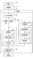
- FIG. 4 is a flowchart showing the control process 160 executed by the control device 21.
- the control device 21 executes air conditioning control for the air conditioning device 10.
- the control device 21 executes heater control for the heater 1.
- step 163 the control device 21 executes a moisture determination calculation for determining whether or not the amount of surface moisture exceeds a predetermined threshold value.
- a calculation for determining whether or not the relative humidity on the surface of the heater 1 exceeds 100% is executed.
- the relative humidity at the surface temperature is obtained based on the humidity of the air and the surface temperature of the heater 1 before energization.
- the surface moisture accumulation time is estimated based on the stop time before the heater 1 is started.
- it is determined that the relative humidity on the surface of the heater 1 is 100%, and the duration of the state is regarded as the surface moisture accumulation time, and the surface moisture accumulated on the surface of the heater 1 is determined. Find the amount.
- step 164 the control device 21 determines whether or not there is moisture on the surface of the heater 1 that exceeds a predetermined threshold value.
- the process of step 164 is a process of determining whether or not a wet state.
- the processing in step 163 and step 164 provides the moisture determination unit 44.
- These steps 163 and 164 can be configured to perform one of the various processes described above.
- the control process 160 proceeds to step 165. If the wet state is affirmed in step 164 (YES), the control process 160 proceeds to step 171.
- step 165 the control device 21 performs normal control.
- step 166 the control device 21 sets a normal output.
- the normal output is set based on the target temperature signal supplied from the target temperature signal source 27.
- Step 165 provides the normal output setting unit 41.
- step 167 the control device 21 sets a normal energization schedule.
- Step 167 provides the normal control unit 42.
- step 168 the control device 21 controls the power supplied to the heater 1 according to the normal energization schedule. As a result, the temperature of the heater 1 quickly rises to the target temperature, that is, the radiation temperature.
- the normal energization schedule is set so as to supply the rated power allowed for heating the heater 1 so as to reach the target temperature from the initial temperature.
- the heater 1 is heated so as to reach the target temperature from the initial temperature over a relatively short first time.
- the normal energization schedule is set so as to provide a quick warm feeling to the user while considering the durability of the heater 1.
- Control device 21 executes suppression control in step 171.
- the control device 21 increases the temperature of the heater 1 over time more slowly than the normal control.
- the control device 21 sets a suppression time.
- Step 172 provides the suppression time setting unit 45.
- the control device 21 sets a suppression temperature.
- Step 173 provides the suppression temperature setting part 46.
- the control device 21 sets a suppression energization schedule.
- Step 174 provides the suppression control unit 47.
- step 168 the control device 21 controls the power supplied to the heater 1 in accordance with the suppression energization schedule. Thereby, the temperature of the heater 1 reaches the target temperature after passing through the suppression temperature for the suppression time. In the suppression control, the heater 1 is heated more slowly than in the normal control.
- the suppression energization schedule suppresses the power supplied to the heater 1 more than the power in normal control.
- the heater 1 is heated so as to reach the target temperature from the initial temperature over a second time longer than the first time.
- the suppression energization schedule is set so that the temperature of the heater 1 reaches the target temperature after the amount of surface moisture is sufficiently reduced.
- step 165 After passing through step 171. Thereby, after the start of the heater 1 is commanded, the normal control is executed after the suppression control is executed.
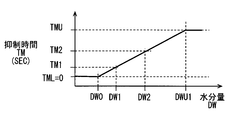
- FIG. 5 shows the setting characteristics of the suppression time TM in the suppression time setting unit 45 and step 172.
- the horizontal axis indicates the water content DW.
- the vertical axis represents the suppression time TM.
- the suppression time TM is set longer as the moisture amount DW increases.
- the suppression time TM is set to the lower limit value TML.
- the lower limit value TML is zero (0). Therefore, even if there is surface moisture, the suppression control is not executed when the amount is small.
- the lower limit value DW0 is set to a value that does not cause noticeable steam or odor even when the amount of water suddenly boils and evaporates.
- the suppression time TM is limited to the upper limit value TMU. This is because the reason for using the heater 1 is diminished if the suppression time TM is too long.
- the upper limit value TMU is desirably set so as to provide the user with a sense of warmth faster than the heating by the air conditioner 10.
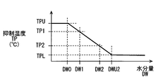
- FIG. 6 shows setting characteristics of the suppression temperature TP in the suppression temperature setting unit 46 and step 173.
- the horizontal axis indicates the water content DW.
- the vertical axis represents the suppression temperature TP.
- the suppression temperature TP is set lower as the moisture amount DW increases.
- the suppression temperature TP is set to the upper limit value TPU.
- the upper limit value TPU is a target temperature set in normal control. Therefore, even if there is surface moisture, the suppression control is not executed when the amount is small.
- the lower limit value DW0 is set to a value that does not cause noticeable steam or odor even when the amount of water suddenly boils and evaporates.
- the suppression temperature TP is limited to the lower limit value TPL. This is because the reason for using the heater 1 is diminished if the suppression temperature TP is too low.
- the lower limit value TPL is desirably set so that the target temperature can be reached quickly after the suppression time TM has elapsed while suppressing the intense boiling and evaporation of surface moisture.
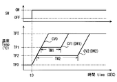
- FIG. 7 shows an example of the operation of the heater 1 according to this embodiment.
- the horizontal axis indicates time.
- the upper row shows the activation signal supplied from the activation signal source 22.
- the lower row shows the temperature of the heater 1.
- activation of heater 1 is commanded.
- the temperature of the heater 1 rises from the initial temperature TP0 toward the target temperature TPT.
- Waveform CV0 corresponds to a normal energization schedule.
- the temperature of the heater 1 rises so as to draw a waveform delayed from the waveform CV0.
- waveforms CV1 and CV2 are illustrated.
- the suppression time TM1 and the suppression temperature TP1 are set, and the suppression energization schedule is set based on these.
- the temperature of the heater 1 changes so as to draw a waveform CV1.
- the temperature of the heater 1 is suppressed to the suppression temperature TP1 that is lower than the target temperature TPT during the period of the suppression time TM1.
- the surface moisture gradually evaporates. This suppresses phenomena such as steam and odor caused by sudden boiling of surface moisture.
- the suppression time TM2 and the suppression temperature TP2 are set, and the suppression energization schedule is set based on these.
- the temperature of the heater 1 changes so as to draw a waveform CV2.
- the surface moisture gradually evaporates. Even when there is a relatively large amount of surface moisture, the amount of moisture can be reduced. This suppresses phenomena such as steam and odor caused by sudden boiling of surface moisture.
- the heater 1 when the wet state is not determined, the heater 1 is heated by the normal control unit 42 so as to reach the target temperature TPT over the first time.
- the heater 1 when the wet state is determined, after the heater 1 is heated by the suppression control unit 47, the heater 1 is heated by the normal control unit 42.
- the heater 1 is heated by the suppression control unit 47 and the normal control unit 42 so as to reach the target temperature TPT over a second time longer than the first time.
- the heater 1 when activation of the heater 1 is commanded, the heater 1 is heated. When surface moisture is not detected, the heater 1 is rapidly heated toward the target temperature. Therefore, a warm feeling is quickly provided to the user. On the other hand, when surface moisture is detected, the heater 1 is heated to a target temperature after being heated to a suppression temperature lower than the target temperature by the suppressed power. Surface moisture is reduced by the suppression temperature. For this reason, the amount of surface moisture at the time when the heater 1 reaches the target temperature is less than the time when the activation is commanded. Therefore, a large amount of surface moisture is rapidly heated by the target temperature, and rapid and large-scale boiling and / or rapid and large-scale evaporation is suppressed.
- the heater 1 is employed in which the temperature of the contact portion is greatly reduced when an object comes into contact. Such a heater 1 can employ a high target temperature. According to this embodiment, even when a high target temperature is adopted, problems caused by boiling and / or evaporation of surface moisture can be suppressed.
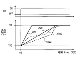
- This embodiment is a modification based on the preceding embodiment.
- the temperature of the heater 1 rises in steps. Instead of this, the temperature of the heater 1 may rise continuously.
- the temperature of the heater 1 in the suppression control may rise along a straight line inclined from the initial temperature TP0 toward the target temperature TPT as shown in the waveform CV21. Even in this case, boiling and evaporation of the surface moisture are suppressed as compared with the waveform CV0 in the normal control. Further, the temperature of the heater 1 may rise along a plurality of inclined straight lines as shown in the waveform CV22. Further, the temperature of the heater 1 may rise along a curve as shown in the waveform CV23. Even if these waveforms are employed, the same effect as the above embodiment can be obtained.
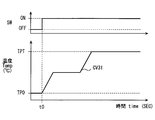
- the temperature of the heater 1 is from the initial temperature TP0 toward the target temperature TPT, as shown in the waveform CV31, regardless of whether or not it is wet. Ascend slowly.
- the waveform CV31 is set so as to suppress the rapid boiling and / or evaporation of surface moisture while realizing the provision of warmth faster than the air conditioner 10 for the user. According to this embodiment, it is not necessary to provide the moisture determination unit 44.
- the heater 1 is heated by the normal control unit 42 after the heater 1 is heated by the suppression control unit 47. According to this embodiment, the speed of provision of warmth is somewhat impaired, but problems due to rapid boiling and / or evaporation of surface moisture are suppressed.
- the vehicle heater 1 is exemplified. Instead of this, the heater 1 may be installed in a household room or a business office room.
- the surface of the heater 1 may be exposed toward the room.
- a heat resistant interior material may be disposed on the surface of the heater 1.
- a fiber material or a fabric material as an interior material may be provided on the surface of the heater 1.
- the suppression control maintains the temperature of the heater 1 at the suppression temperature over the suppression time.
- the power supplied to the heater 1 over the suppression time may be maintained at the suppression power.
- the suppression power can be a standard power for realizing the suppression temperature.
Abstract
A heater 1 is installed indoors and is heated to a target temperature. The heater 1 is controlled by a control device 21. The control device 21 has a normal control unit for heating the heater 1 so as to reach a target temperature. The control device 21 further has a reducing control unit for heating the heater 1 to a reduced temperature lower than the target temperature at reduced power, in order to decrease surface moisture adhering to the surface of the heater 1. When a command to start up the heater 1 is issued, after the heater 2 has been heated by the reducing control unit, the heater 1 is then heated by the normal control unit. Surface moisture is decreased by the reduced temperature. Therefore, sudden boiling and/or sudden evaporation of surface moisture due to the target temperature can be reduced.
Description
この出願は、2014年12月10日に日本に出願された特許出願第2014-250181号を基礎としており、基礎の出願の内容を、全体的に、参照により援用している。
This application is based on patent application No. 2014-250181 filed in Japan on December 10, 2014, and the content of the basic application is incorporated by reference in its entirety.
この明細書における開示は、室内に設置される室内用のヒータ装置に関する。
The disclosure in this specification relates to an indoor heater device installed indoors.
特許文献1-特許文献5には、室内に設けられ、人に温感を提供するヒータ装置が記載されている。ヒータ装置は、暖房用ヒータ装置とも呼ぶことができる。ヒータ装置は、電熱ヒータ装置とも呼ぶことができる。ヒータ装置の一形態は、輻射によって人に温感を与える輻射ヒータ装置とも呼ばれる。ヒータ装置のひとつの用途は、車両用である。特許文献1-特許文献5に記載されるヒータ装置は、室内に面して配置される。
Patent Documents 1 to 5 describe a heater device that is provided indoors and provides a warm feeling to a person. The heater device can also be called a heater device for heating. The heater device can also be referred to as an electric heater device. One form of the heater device is also called a radiation heater device that gives a person a warm feeling by radiation. One application of the heater device is for vehicles. The heater device described in Patent Document 1 to Patent Document 5 is arranged facing the room.
室内に置かれた部材の表面、または室を区画する壁の表面には、水分が付着することがある。例えば、窓やドアから雨または雪が吹き込むことにより、表面上に水分が付着することがある。また、空気中の湿度に起因して、表面上に結露が生じることがある。例えば、結露は、室内の湿度と、壁の温度とに依存して生じる。また、車両においては、狭い室内と、外気の温度を伝えやすい構造とに起因して、結露が顕著な場合がある。また、車両の中には雨や雪が吹き込みやすいから、車室内の表面は濡れやすい。
• Moisture may adhere to the surface of a member placed in a room or the surface of a wall that partitions the room. For example, when rain or snow blows from a window or door, moisture may adhere to the surface. Also, condensation may occur on the surface due to humidity in the air. For example, condensation occurs depending on the humidity in the room and the temperature of the wall. Further, in a vehicle, condensation may be noticeable due to a narrow room and a structure that easily transmits the temperature of the outside air. Further, since rain and snow are likely to blow into the vehicle, the surface of the passenger compartment is easily wet.
ヒータ装置の表面上に所定量を上回る水分または水滴がある場合にヒータ装置が発熱すると、水分が沸騰し、蒸発する。このとき、湯気が立ち昇ったり、臭いを生じたりすることがある。このような現象は、利用者によって知覚されることがあるが、水分の沸騰および/または蒸発は、利用者によって知覚されないように抑制されることが望ましい。上述の観点において、または言及されていない他の観点において、室内用ヒータ装置にはさらなる改良が求められている。
When the heater device generates heat when water or water droplets exceeding a predetermined amount are present on the surface of the heater device, the water boils and evaporates. At this time, steam may rise or cause odor. Such a phenomenon may be perceived by the user, but it is desirable that the boiling and / or evaporation of moisture be suppressed so that it is not perceived by the user. In view of the above or other aspects not mentioned, there is a need for further improvements in room heater devices.
開示されるひとつの目的は、ヒータ装置上の水分の沸騰および/または水分の急激な蒸発を抑制できる室内用ヒータ装置を提供することである。
One object disclosed is to provide an indoor heater device capable of suppressing boiling of water on the heater device and / or rapid evaporation of moisture.
開示される他のひとつの目的は、迅速な温感の提供と、水分の沸騰および/または水分の急激な蒸発に起因する不具合の抑制とを両立できる室内用ヒータ装置を提供することである。
Another object of the disclosure is to provide an indoor heater device that can provide both rapid warmth and suppression of defects caused by boiling of water and / or rapid evaporation of moisture.
この明細書における開示は、以下の技術的手段を採用する。なお、特許請求の範囲および/またはこの項に記載した括弧内の符号は、ひとつの態様として後述する実施形態に記載の具体的手段との対応関係を示すものであって、技術的範囲を限定するものではない。
The disclosure in this specification adopts the following technical means. In addition, the code | symbol in the parenthesis described in a claim and / or this clause shows the correspondence with the specific means as described in embodiment mentioned later as one aspect, Comprising: Technical scope is limited. Not what you want.
開示は、ヒータ装置を提供する。ヒータ装置は、室内に設置され目標温度に加熱されるヒータと、ヒータが目標温度に到達するようにヒータを加熱する通常制御部と、ヒータの表面に付着している水分を減少させるように抑制された電力によってヒータを目標温度より低い抑制温度に加熱する抑制制御部とを備える。ヒータの起動が指令された後に、抑制制御部によりヒータが加熱される。抑制制御部によりヒータが加熱された後に、通常制御部によりヒータが加熱される。
Disclosure provides heater device. The heater device is installed in a room and heated to a target temperature, a normal control unit that heats the heater so that the heater reaches the target temperature, and a suppression to reduce moisture adhering to the surface of the heater A suppression control unit that heats the heater to a suppression temperature lower than the target temperature by the generated electric power. After the activation of the heater is commanded, the heater is heated by the suppression control unit. After the heater is heated by the suppression control unit, the heater is heated by the normal control unit.
ヒータの起動が指令されると、ヒータが加熱される。ヒータは、抑制された電力によって目標温度より低い抑制温度に加熱された後に、目標温度に加熱される。ヒータの表面に水分が付着している場合には、抑制温度によって水分が減少する。よって、ヒータの表面に付着している水分が、目標温度によって急激に加熱され、急激な沸騰および/または急激な蒸発を発生することが抑制される。
When the heater is commanded to start, the heater is heated. The heater is heated to a target temperature after being heated to a suppression temperature lower than the target temperature by the suppressed power. If moisture is attached to the surface of the heater, the moisture is reduced by the suppression temperature. Therefore, the moisture adhering to the surface of the heater is suddenly heated by the target temperature, and rapid boiling and / or rapid evaporation is suppressed.
図面を参照しながら、複数の実施形態を説明する。各形態において、先行する形態で説明した事項に対応する部分には同一の参照符号を付して重複する説明を省略する場合がある。また、後続の実施形態においては、先行する実施形態で説明した事項に対応する部分に百以上の位だけが異なる参照符号を付することにより対応関係を示し、重複する説明を省略する場合がある。各形態において、構成の一部のみを説明している場合は、構成の他の部分については他の形態の説明を参照し適用することができる。
A plurality of embodiments will be described with reference to the drawings. In each embodiment, portions corresponding to the matters described in the preceding embodiment may be denoted by the same reference numerals and redundant description may be omitted. Further, in the following embodiments, the correspondence corresponding to the matters corresponding to the matters described in the preceding embodiments is indicated by adding reference numerals that differ only by one hundred or more, and redundant description may be omitted. . In each embodiment, when only a part of the structure is described, the other parts of the structure can be applied with reference to the description of the other forms.
(第1実施形態)
図1において、この実施形態に係るヒータ装置は、輻射熱を利用するヒータ1を有する。ヒータ1は、ヒータ素子とも呼ばれる。ヒータ1は、道路走行車両、船舶、航空機などの移動体の室内に設置されている。ヒータ1は、住宅、事業所などの室内に設けてもよい。ヒータ1は、室内を少なくとも暖房する空調装置10の一部を構成している。ヒータ1は、移動体に搭載された電池、発電機などの電源から給電されて発熱する電気的なヒータである。ヒータ1は、薄い板状に形成されている。ヒータ1は、電力が供給されると発熱する。ヒータ1は、その表面と垂直な方向に位置付けられた対象物を暖めるために、主としてその表面と垂直な方向へ向けて輻射熱Rを放射する。 (First embodiment)
In FIG. 1, the heater device according to this embodiment includes a heater 1 that uses radiant heat. The heater 1 is also called a heater element. The heater 1 is installed in a room of a moving body such as a road traveling vehicle, a ship, and an aircraft. The heater 1 may be provided in a room such as a house or a business office. The heater 1 constitutes a part of anair conditioner 10 that at least heats the room. The heater 1 is an electric heater that generates heat by being fed from a power source such as a battery or a generator mounted on a moving body. The heater 1 is formed in a thin plate shape. The heater 1 generates heat when electric power is supplied. The heater 1 radiates radiant heat R mainly in a direction perpendicular to the surface in order to warm an object positioned in a direction perpendicular to the surface.
図1において、この実施形態に係るヒータ装置は、輻射熱を利用するヒータ1を有する。ヒータ1は、ヒータ素子とも呼ばれる。ヒータ1は、道路走行車両、船舶、航空機などの移動体の室内に設置されている。ヒータ1は、住宅、事業所などの室内に設けてもよい。ヒータ1は、室内を少なくとも暖房する空調装置10の一部を構成している。ヒータ1は、移動体に搭載された電池、発電機などの電源から給電されて発熱する電気的なヒータである。ヒータ1は、薄い板状に形成されている。ヒータ1は、電力が供給されると発熱する。ヒータ1は、その表面と垂直な方向に位置付けられた対象物を暖めるために、主としてその表面と垂直な方向へ向けて輻射熱Rを放射する。 (First embodiment)
In FIG. 1, the heater device according to this embodiment includes a heater 1 that uses radiant heat. The heater 1 is also called a heater element. The heater 1 is installed in a room of a moving body such as a road traveling vehicle, a ship, and an aircraft. The heater 1 may be provided in a room such as a house or a business office. The heater 1 constitutes a part of an
室内には、乗員12が着座するための座席11が設置されている。ヒータ1は、乗員12の足元に輻射熱Rを放射するように室内に設置されている。ヒータ1は、空調装置10の起動直後において、乗員12に対して即効的に暖かさを提供するためのヒータとして利用することができる。ヒータ1は、室内の壁面に設置される。ヒータ1は、想定される通常の姿勢の乗員12に対向するように設置される。例えば、道路走行車両は、ハンドル14を支持するためのステアリングコラム13を有している。ヒータ1は、ステアリングコラム13の下面に設置することができる。
In the room, there is a seat 11 for the passenger 12 to sit. The heater 1 is installed indoors so as to radiate radiant heat R to the feet of the occupant 12. The heater 1 can be used as a heater for immediately providing warmth to the occupant 12 immediately after activation of the air conditioner 10. The heater 1 is installed on a wall surface in the room. The heater 1 is installed so as to face the occupant 12 in the assumed normal posture. For example, the road traveling vehicle has a steering column 13 for supporting the handle 14. The heater 1 can be installed on the lower surface of the steering column 13.
ヒータ1は、その表面が室内に向けて露出するように設置されている。ヒータ1は、乗員12がヒータ1の表面に直接に触れることを阻止するためのカバー部材を有することなく、実質的に室内に露出している。ヒータ1は、金網や樹脂などで作られたカバー部材、または内装材料としての布地を、室内側に有していてもよい。
The heater 1 is installed such that its surface is exposed toward the room. The heater 1 is substantially exposed indoors without having a cover member for preventing the passenger 12 from directly touching the surface of the heater 1. The heater 1 may have a cover member made of a wire mesh or a resin, or a fabric as an interior material on the indoor side.
ヒータ1は、制御装置(ECU)21によって制御される。制御装置21は、ヒータ1への通電のON、OFF、および通電中の電力量を制御する。
The heater 1 is controlled by a control unit (ECU) 21. The control device 21 controls ON / OFF of energization to the heater 1 and the amount of electric power during energization.
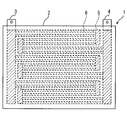
図2において、ヒータ1は、ほぼ四角形の薄い板状に形成されている。ヒータ1は、面状ヒータ、または平面ヒータとも呼ばれる。ヒータ1は、基板部2と、複数の電極3、4、5と、複数の発熱体6とを有する。電極3、4は、電力供給用の外部電極である。電極5は、複数の発熱体6を並列および/または直列に接続するための内部接続用の電極である。基板部2には、複数の電極5と、複数の発熱体6とが埋設されている。図中には、電極5と発熱体6とを示すために、ハッチングが付されている。ヒータ1は、主として表面と垂直な方向に向けて輻射熱Rを放射する面状ヒータとも呼ぶことができる。
In FIG. 2, the heater 1 is formed in a substantially rectangular thin plate shape. The heater 1 is also called a planar heater or a flat heater. The heater 1 includes a substrate portion 2, a plurality of electrodes 3, 4, 5 and a plurality of heating elements 6. The electrodes 3 and 4 are external electrodes for supplying power. The electrode 5 is an internal connection electrode for connecting a plurality of heating elements 6 in parallel and / or in series. A plurality of electrodes 5 and a plurality of heating elements 6 are embedded in the substrate unit 2. In the drawing, hatching is added to show the electrode 5 and the heating element 6. The heater 1 can also be called a planar heater that radiates radiant heat R mainly in a direction perpendicular to the surface.
基板部2は、優れた電気絶縁性を提供し、かつ高温に耐える樹脂材料によって作られている。基板部2は、表面を提供する。基板部2は、平板状に形成されている。基板部2は、設置場所の壁面に対応した曲面を与えられる。基板部2は、その形状を維持できる剛性を有している。基板部2は、壁面に沿うように変形するための可撓性をもつことができる。基板部2は、熱可塑性樹脂によって作ることができる。基板部2は、多層基板である。基板部2は、電極3、4、5および、発熱体6を支持するための部材である。
The substrate part 2 is made of a resin material that provides excellent electrical insulation and withstands high temperatures. The substrate unit 2 provides a surface. The substrate part 2 is formed in a flat plate shape. The board part 2 is given a curved surface corresponding to the wall surface of the installation place. The board | substrate part 2 has the rigidity which can maintain the shape. The board | substrate part 2 can have the flexibility for deform | transforming along a wall surface. The substrate part 2 can be made of a thermoplastic resin. The substrate unit 2 is a multilayer substrate. The substrate unit 2 is a member for supporting the electrodes 3, 4, 5 and the heating element 6.
発熱体6は、基板部2の内部に埋設されている。よって、発熱体6は、基板部2の表面には露出していない。発熱体6は、基板部2によって保護されている。発熱体6は、基板部2の面と平行な薄い板状に形成されている。発熱体6は、通電によって供給される熱によって輻射熱Rを放射可能である。発熱体6は、所定の放射温度に加熱されることによって、乗員12、すなわち人に暖かさを感じさせる輻射熱Rを放射することができる。
The heating element 6 is embedded in the substrate part 2. Therefore, the heating element 6 is not exposed on the surface of the substrate unit 2. The heating element 6 is protected by the substrate unit 2. The heating element 6 is formed in a thin plate shape parallel to the surface of the substrate unit 2. The heating element 6 can radiate radiant heat R by heat supplied by energization. The heating element 6 can radiate radiant heat R that makes the occupant 12, that is, a person feel warm, by being heated to a predetermined radiation temperature.
電極3、4、5は、通電されたときに発熱体6より発熱量が少ない材料によって作られている。電極3、4、5は、複数の発熱体6へ均等に電流を分配できるように固有抵抗が低い材料によって作られている。電極3、4、5は、金属材料によって作ることができる。電極3、4、5は、錫合金によって作ることができる。電極3、4、5は、銅、銀、錫を含む合金によって作ることができる。また、電極3、4、5は、銅合金またはアルミニウム合金などの良導体材料によっても作ることができる。
The electrodes 3, 4, and 5 are made of a material that generates less heat than the heating element 6 when energized. The electrodes 3, 4, and 5 are made of a material having a low specific resistance so that current can be evenly distributed to the plurality of heating elements 6. The electrodes 3, 4, 5 can be made of a metal material. The electrodes 3, 4, 5 can be made of a tin alloy. The electrodes 3, 4, and 5 can be made of an alloy containing copper, silver, and tin. The electrodes 3, 4, and 5 can also be made of a good conductor material such as a copper alloy or an aluminum alloy.
発熱体6は、通電によって発熱する材料によって作られている。発熱体6は、金属材料によって作ることができる。発熱体6は、錫合金によって作ることができる。発熱体6は、銅、銀、錫を含む合金によって作ることができる。また、発熱体6は、ステンレス合金、ニッケル-クロム合金、アルミニウム合金などの電熱線材料によっても作ることができる。
The heating element 6 is made of a material that generates heat when energized. The heating element 6 can be made of a metal material. The heating element 6 can be made of a tin alloy. The heating element 6 can be made of an alloy containing copper, silver, and tin. The heating element 6 can also be made of a heating wire material such as a stainless alloy, a nickel-chromium alloy, or an aluminum alloy.
この実施形態では、ヒータ1は、その表面に物体が接触すると、その物体への熱伝達によってその接触部分における温度が大幅に低下するように形成されている。物体としてヒトの体を想定することができる。ヒータ1は、短期間の接触時にヒトが過剰な熱により不快感を感じない温度にまで接触部分の温度が低下するように構成されている。
In this embodiment, the heater 1 is formed such that when an object comes into contact with the surface thereof, the temperature at the contact portion is significantly lowered by heat transfer to the object. A human body can be assumed as the object. The heater 1 is configured such that the temperature of the contact portion is lowered to a temperature at which a human does not feel uncomfortable due to excessive heat during short-term contact.
ヒータ1は、多様な構造によって提供することができる。従来技術として列挙された先行技術文献には、ヒータ1として利用可能な装置が記載されている。これら先行技術文献の記載内容は、この明細書に記載された技術的要素の説明として、参照によって導入ないし援用される。
The heater 1 can be provided by various structures. Prior art documents listed as prior art describe devices that can be used as the heater 1. The contents of these prior art documents are introduced or incorporated by reference as an explanation of the technical elements described in this specification.
ヒータ1の表面は、水分の付着を抑制するための撥水性を有する。ヒータ1の表面には、撥水性の高い材料が用いられている。具体的には、水滴の接触角を100°以上にすることができるシリコン系、またはフッ素系の撥水材料が用いられている。ヒータ1の表面上に水滴が付着しても、水滴が流れ落ちやすい。これにより、ヒータ1の表面における保水量が抑制される。このため、ヒータ1が起動された直後における水の急激な沸騰および/または蒸発が抑制される。
The surface of the heater 1 has water repellency for suppressing adhesion of moisture. A material having high water repellency is used for the surface of the heater 1. Specifically, a silicon-based or fluorine-based water repellent material that can make the contact angle of water droplets 100 ° or more is used. Even if water droplets adhere to the surface of the heater 1, the water droplets are likely to flow down. Thereby, the water retention amount on the surface of the heater 1 is suppressed. For this reason, rapid boiling and / or evaporation of water immediately after the heater 1 is activated is suppressed.
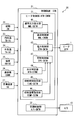
図3は、制御システム20を示す。制御システム20において、制御装置(ECU)21は、電子制御装置(Electronic Control Unit)である。電子制御装置は、少なくとも
ひとつの演算処理装置(CPU)と、プログラムとデータとを記憶する記憶媒体としての少なくともひとつのメモリ装置(MMR)とを有する。電子制御装置は、コンピュータによって読み取り可能な記憶媒体を備えるマイクロコンピュータによって提供される。記憶媒体は、コンピュータによって読み取り可能なプログラムを非一時的に格納している。記憶媒体は、半導体メモリまたは磁気ディスクなどによって提供されうる。電子制御装置は、ひとつのコンピュータ、またはデータ通信装置によってリンクされた一組のコンピュータ資源によって提供されうる。プログラムは、電子制御装置によって実行されることによって、電子制御装置をこの明細書に記載される装置として機能させ、この明細書に記載される方法を実行するように電子制御装置を機能させる。電子制御装置は、多様な要素を提供する。それらの要素の少なくとも一部は、機能を実行するための手段と呼ぶことができ、別の観点では、それらの要素の少なくとも一部は、構成として解釈されるブロック、または構成として解釈されるモジュールと呼ぶことができる。 FIG. 3 shows thecontrol system 20. In the control system 20, a control device (ECU) 21 is an electronic control unit. The electronic control device has at least one arithmetic processing unit (CPU) and at least one memory device (MMR) as a storage medium for storing programs and data. The electronic control device is provided by a microcomputer including a computer-readable storage medium. The storage medium stores a computer-readable program non-temporarily. The storage medium can be provided by a semiconductor memory or a magnetic disk. The electronic control unit can be provided by a computer or a set of computer resources linked by a data communication device. The program is executed by the electronic control device to cause the electronic control device to function as the device described in this specification, and to function the electronic control device to perform the method described in this specification. The electronic control device provides various elements. At least some of those elements can be referred to as means for performing the function, and in another aspect, at least some of those elements are blocks that are interpreted as a configuration, or modules that are interpreted as a configuration. Can be called.
ひとつの演算処理装置(CPU)と、プログラムとデータとを記憶する記憶媒体としての少なくともひとつのメモリ装置(MMR)とを有する。電子制御装置は、コンピュータによって読み取り可能な記憶媒体を備えるマイクロコンピュータによって提供される。記憶媒体は、コンピュータによって読み取り可能なプログラムを非一時的に格納している。記憶媒体は、半導体メモリまたは磁気ディスクなどによって提供されうる。電子制御装置は、ひとつのコンピュータ、またはデータ通信装置によってリンクされた一組のコンピュータ資源によって提供されうる。プログラムは、電子制御装置によって実行されることによって、電子制御装置をこの明細書に記載される装置として機能させ、この明細書に記載される方法を実行するように電子制御装置を機能させる。電子制御装置は、多様な要素を提供する。それらの要素の少なくとも一部は、機能を実行するための手段と呼ぶことができ、別の観点では、それらの要素の少なくとも一部は、構成として解釈されるブロック、または構成として解釈されるモジュールと呼ぶことができる。 FIG. 3 shows the
電子制御装置が提供する手段および/または機能は、実体的なメモリ装置に記録されたソフトウェアおよびそれを実行するコンピュータ、ソフトウェアのみ、ハードウェアのみ、あるいはそれらの組合せによって提供することができる。例えば、電子制御装置がハードウェアである電子回路によって提供される場合、それは多数の論理回路を含むデジタル回路、またはアナログ回路によって提供することができる。
The means and / or functions provided by the electronic control device can be provided by software recorded in a substantial memory device and a computer that executes the software, software only, hardware only, or a combination thereof. For example, if the electronic controller is provided by an electronic circuit that is hardware, it can be provided by a digital circuit including a number of logic circuits, or an analog circuit.
制御システムは、複数の信号源を有する。信号源はセンサまたは制御装置によって提供される。信号源は、情報を示す信号を出力する。信号は、独立した信号線を経由して、またはLANなどのデータ回線を経由して制御装置に入力される。制御装置は、信号が示す情報をメモリ装置に格納されることにより、情報を取得する。制御システムは、制御装置によって制御処理を実行する。制御システムは、制御処理によってひとつまたは複数の制御対象を制御する。
The control system has a plurality of signal sources. The signal source is provided by a sensor or control device. The signal source outputs a signal indicating information. The signal is input to the control device via an independent signal line or a data line such as a LAN. The control device acquires information by storing the information indicated by the signal in the memory device. The control system executes control processing by the control device. The control system controls one or a plurality of control objects by a control process.
制御システム20は、ヒータ(HTR)1と、空調装置(A/C)10とを制御する。空調装置10は、室内を少なくとも暖房する。空調装置10は、さらに、冷房および/または換気を提供するように構成されてもよい。
The control system 20 controls the heater (HTR) 1 and the air conditioner (A / C) 10. The air conditioner 10 heats at least the room. The air conditioner 10 may be further configured to provide cooling and / or ventilation.
制御システム20は、ヒータ1および空調装置10の起動を指令するための起動指令信号を制御装置21に供給する起動信号源(SW)22を備える。起動信号源22は、起動スイッチによって提供することができる。また、起動信号源22は、予め定められた時刻が到来すると起動指令信号を出力するタイマー装置、または、室内に利用者が入る前にヒータ1を予熱するために自動的に起動指令信号を出力するプレ運転装置によっても提供することができる。
The control system 20 includes an activation signal source (SW) 22 that supplies an activation command signal for instructing activation of the heater 1 and the air conditioner 10 to the control device 21. The activation signal source 22 can be provided by an activation switch. The start signal source 22 outputs a start command signal when a predetermined time arrives, or automatically outputs a start command signal to preheat the heater 1 before the user enters the room. It can also be provided by a pre-running device.
制御システム20は、室内および室外の空調に関連する情報を制御装置21に供給する複数の信号源を備える。制御システム20は、室内の空気の温度を示す内気温度信号を制御装置21に供給するための内気温信号源(TR-SC)23を備える。制御システム20は、室外の空気の温度を示す外気温度信号を制御装置21に供給するための外気温信号源(TA-SC)24を備える。制御システム20は、室内の空気の湿度を示す湿度信号を制御装置21に供給するための湿度信号源(RH-SC)25を備える。湿度信号源25は、室内の部材表面における水分量を評価するための信号を制御装置21に供給する信号源でもある。制御システム20は、外部のシステムから、室内の部材表面における水分量を評価するために利用可能な情報を制御装置21に供給するための通信機(COMM)26を備える。制御システム20は、ヒータ1の目標温度信号を制御装置21に供給するための目標温度信号源(VR)27を備える。
The control system 20 includes a plurality of signal sources that supply information related to indoor and outdoor air conditioning to the control device 21. The control system 20 includes an internal air temperature signal source (TR-SC) 23 for supplying an internal air temperature signal indicating the temperature of indoor air to the control device 21. The control system 20 includes an outside air temperature signal source (TA-SC) 24 for supplying an outside air temperature signal indicating the temperature of outdoor air to the control device 21. The control system 20 includes a humidity signal source (RH-SC) 25 for supplying a humidity signal indicating the humidity of indoor air to the control device 21. The humidity signal source 25 is also a signal source that supplies a signal for evaluating the amount of water on the surface of the indoor member to the control device 21. The control system 20 includes a communication device (COMM) 26 for supplying information that can be used to evaluate the amount of moisture on the surface of a member in the room from an external system to the control device 21. The control system 20 includes a target temperature signal source (VR) 27 for supplying a target temperature signal of the heater 1 to the control device 21.
制御装置21は、ヒータ1を制御するためのヒータ制御部(HTR-CNTM)31を備える。ヒータ制御部31は、ヒータ1へ供給される電力を制御する。制御装置21は、空調制御部(A/C-CNTM)32を有する。空調制御部32は、空調装置10を制御する。制御装置21は、空調装置10を制御することを主任務とする装置である場合がある。ヒータ制御部31は、制御装置21に付加的に加えられた制御部によって提供することができる。
The control device 21 includes a heater control unit (HTR-CNTM) 31 for controlling the heater 1. The heater control unit 31 controls the power supplied to the heater 1. The control device 21 includes an air conditioning control unit (A / C-CNTM) 32. The air conditioning control unit 32 controls the air conditioner 10. The control device 21 may be a device whose main duty is to control the air conditioner 10. The heater control unit 31 can be provided by a control unit added to the control device 21.
ヒータ制御部31は、ヒータ1による出力を設定するための通常出力設定部(NML-SETM)41を備える。通常出力設定部41は、利用者が手動操作によって設定したヒータ1の目標温度に基づいて、ヒータ1が通常運転されるときのヒータ1の温度を設定する。目標温度は、目標出力とも呼ばれる。例えば、制御システム20は、ヒータ1の出力を高中低の三段階に設定する目標温度信号源27を備えることができる。通常出力設定部41は、目標温度信号源27に応答して、目標温度を設定する。ヒータ1は、輻射温度に加熱されることによって輻射熱を放射する。よって、通常出力設定部41は、輻射温度の範囲内において目標温度を設定する。
The heater control unit 31 includes a normal output setting unit (NML-SETM) 41 for setting the output from the heater 1. The normal output setting unit 41 sets the temperature of the heater 1 when the heater 1 is normally operated based on the target temperature of the heater 1 set by the user by manual operation. The target temperature is also called a target output. For example, the control system 20 can include a target temperature signal source 27 that sets the output of the heater 1 in three stages of high, medium, and low. The normal output setting unit 41 sets the target temperature in response to the target temperature signal source 27. The heater 1 emits radiant heat by being heated to a radiant temperature. Therefore, the normal output setting unit 41 sets the target temperature within the range of the radiation temperature.
ヒータ制御部31は、通常制御部(NML-CNTM)42を備える。通常制御部42は、通常出力設定部41によって設定された目標温度に向けて迅速にヒータ1の出力が上昇し、維持されるように通常通電スケジュールを設定する。通常制御部42は、第1立ち上げ時間の間にヒータ1の温度が初期温度から目標温度に到達するように通電を制御する。第1立ち上げ時間は、ヒータ1に許容された最も速い立ち上げ時間である。第1立ち上げ時間は、利用者に対して迅速に温感を提供するために設定されている。
The heater control unit 31 includes a normal control unit (NML-CNTM) 42. The normal control unit 42 sets a normal energization schedule so that the output of the heater 1 quickly increases and is maintained toward the target temperature set by the normal output setting unit 41. The normal control unit 42 controls energization so that the temperature of the heater 1 reaches the target temperature from the initial temperature during the first startup time. The first start-up time is the fastest start-up time allowed for the heater 1. The first start-up time is set in order to quickly provide a warm feeling to the user.
ヒータ制御部31は、電力制御部(EPW-CNTM)43を備える。電力制御部43は、ヒータ1への通電量を調節可能な電力制御回路を含む。電力制御部43は、通常制御部42によって設定された通常通電スケジュールに沿ってヒータ1への通電量、すなわち供給電力を調節する。
The heater control unit 31 includes a power control unit (EPW-CNTM) 43. The power control unit 43 includes a power control circuit capable of adjusting the energization amount to the heater 1. The power control unit 43 adjusts the energization amount to the heater 1, that is, the supplied power, according to the normal energization schedule set by the normal control unit 42.
ヒータ制御部31は、水分判定部(WTR-DTMM)44を備える。水分判定部44は、ヒータ1の表面上に所定閾値を上回る水分が付着しているか否かを判定する。以下の説明では、「ヒータ1の表面上に所定閾値を上回る水分が付着している状態」を「濡れ状態」と呼ぶ。また、「ヒータ1の表面上に付着している水分」を「表面水分」と呼ぶ。
The heater control unit 31 includes a moisture determination unit (WTR-DTMM) 44. The moisture determination unit 44 determines whether moisture exceeding a predetermined threshold is attached on the surface of the heater 1. In the following description, “a state in which moisture exceeding a predetermined threshold is attached on the surface of the heater 1” is referred to as a “wet state”. Further, “moisture adhering to the surface of the heater 1” is referred to as “surface moisture”.
水分判定部44は、室内の壁の内面が濡れ状態であるか否かを判定しているともいえる。水分判定部44は、ヒータ1が起動されるときに、濡れ状態であるか否かを判定する。水分判定部44は、濡れ状態にある場合、水分検知信号を出力する。水分判定部44は、ヒータ1の表面に所定閾値を上回る水分が実際に付着しているか否かを検出するセンサおよび/または演算処理により提供される場合がある。水分判定部44は、ヒータ1の表面に所定閾値を上回る水分が付着しているか否かを推定ないしは予測するセンサおよび/または演算処理により提供される場合がある。水分判定部44は、雨または雪に起因する表面水分、および/または結露に起因する表面水分を評価するように構成される。
It can be said that the moisture determination unit 44 determines whether or not the inner surface of the indoor wall is wet. The moisture determination unit 44 determines whether or not the heater 1 is wet when the heater 1 is activated. The moisture determination unit 44 outputs a moisture detection signal when in a wet state. The moisture determination unit 44 may be provided by a sensor and / or calculation process that detects whether or not moisture exceeding a predetermined threshold is actually attached to the surface of the heater 1. The moisture determination unit 44 may be provided by a sensor and / or calculation process that estimates or predicts whether moisture exceeding a predetermined threshold is attached to the surface of the heater 1. The moisture determination unit 44 is configured to evaluate surface moisture caused by rain or snow and / or surface moisture caused by condensation.
この実施形態では、水分判定部44は、結露に起因して濡れ状態であるか否かを判定する。言い換えると、水分判定部44は、ヒータ1が起動されるときに、壁の内面に所定閾値を上回る量の水分が付着しているか否か、または、壁の内面に所定閾値を上回る量の水分が付着する可能性があるか否かを判定する。水分判定部44は、結露判定部とも呼ぶことができる。
In this embodiment, the moisture determination unit 44 determines whether or not the wet state is caused by condensation. In other words, when the heater 1 is started, the moisture determination unit 44 determines whether or not an amount of moisture exceeding a predetermined threshold is attached to the inner surface of the wall, or an amount of moisture exceeding the predetermined threshold on the inner surface of the wall. It is determined whether or not there is a possibility of adhesion. The moisture determination unit 44 can also be referred to as a dew condensation determination unit.
水分判定部44は、結露に起因して濡れ状態である場合、水分検知信号として結露信号を出力するように構成される場合がある。結露の有無および結露量は、ヒータ1の周辺の雰囲気が、ヒータ1の表面上に結露を生じる条件を満たしたことによって推定することができる。結露量は、水分量とも呼ばれる。一例では、水分判定部44は、内気温度、外気温度、および室内空気の湿度の少なくともひとつに基づいて結露量を推定する。これら温度および/または湿度は、空調装置10が備えるセンサを利用して取得することができる。一例では、水分判定部44は、ヒータ1が起動されるときの温度および/または湿度に基づいて結露量を推定する。
The moisture determination unit 44 may be configured to output a condensation signal as a moisture detection signal when it is wet due to condensation. The presence or absence of condensation and the amount of condensation can be estimated when the atmosphere around the heater 1 satisfies the conditions for causing condensation on the surface of the heater 1. The amount of condensation is also called the amount of moisture. In one example, the moisture determination unit 44 estimates the amount of condensation based on at least one of the inside air temperature, the outside air temperature, and the humidity of the room air. These temperature and / or humidity can be acquired using a sensor provided in the air conditioner 10. In one example, the moisture determination unit 44 estimates the amount of condensation based on the temperature and / or humidity when the heater 1 is activated.
水分判定部44は、ヒータ1が起動される前の温度および/または湿度を含む履歴情報に基づいて結露量を推定するように構成される場合がある。一例では、水分判定部44は、先に利用者が部屋を退出したときの室内の絶対湿度と、退室後の内気温度または外気温度の変動量とに基づいて結露量を推定する。例えば、先の利用時における室内の絶対湿度と、先の利用時と今回起動時との室内温度の低下量とに基づいてヒータ1の表面上における結露量を推定することができる。
The moisture determination unit 44 may be configured to estimate the amount of dew condensation based on history information including temperature and / or humidity before the heater 1 is activated. In one example, the moisture determination unit 44 estimates the amount of dew condensation based on the absolute humidity inside the room when the user first leaves the room and the amount of change in the inside air temperature or outside air temperature after leaving the room. For example, the amount of dew condensation on the surface of the heater 1 can be estimated based on the absolute humidity in the room at the time of previous use and the amount of decrease in the room temperature at the time of previous use and at the time of starting this time.
例えば、水分判定部44は、ヒータ1が起動される直前のヒータ1の周辺の温度および/または湿度に基づいて結露量を推定する。例えば、水分判定部44は、ヒータ1の起動より所定時間以上前からの温度および/または湿度の変化に基づいて結露量を推定する。例えば、水分判定部44は、ヒータ1が起動される直前のヒータ1の周辺の温度および/または湿度、およびヒータ1の起動より所定時間以上前からの温度および/または湿度の変化に基づいて結露量を推定する。具体的には、ヒータ1の起動直前の内気温および/または外気温が0℃以下である場合、所定閾値を上回る結露を肯定的に推定することができる。また、ヒータ1の起動直前の温度が0℃以下でなくても、数時間前に常温多湿、例えば内気温度が20℃、湿度が50%RH以上である場合には、所定閾値を上回る結露を肯定的に推定することができる。水分判定部44は、最後に車両が使われた時の温度センサ、湿度センサ、乗車人数の情報、天気の情報など、温度および/または湿度を予測できる情報を用いて車内に残留する水分量を予測する処理を含むことができる。この場合、水分判定部44は、室内に残留する水分量と、起動時における温度情報とに基づいて結露量を推定する。
For example, the moisture determination unit 44 estimates the amount of condensation based on the temperature and / or humidity around the heater 1 immediately before the heater 1 is started. For example, the moisture determination unit 44 estimates the amount of dew condensation based on changes in temperature and / or humidity from a predetermined time or more before the heater 1 is activated. For example, the moisture determination unit 44 condenses based on the temperature and / or humidity around the heater 1 immediately before the heater 1 is activated, and the change in temperature and / or humidity from a predetermined time before the heater 1 is activated. Estimate the amount. Specifically, when the inside air temperature and / or the outside air temperature just before the heater 1 is started is 0 ° C. or less, the dew condensation exceeding a predetermined threshold can be positively estimated. Even if the temperature immediately before starting the heater 1 is not less than 0 ° C., if the room temperature and humidity are several hours ago, for example, the inside air temperature is 20 ° C. and the humidity is 50% RH or more, dew condensation exceeding a predetermined threshold value is generated It can be positively estimated. The moisture determination unit 44 determines the amount of moisture remaining in the vehicle using information that can predict temperature and / or humidity, such as a temperature sensor, a humidity sensor, information on the number of passengers, and weather information when the vehicle is last used. Predictive processing can be included. In this case, the moisture determination unit 44 estimates the amount of condensation based on the amount of moisture remaining in the room and the temperature information at startup.
水分判定部44は、外部のシステムから通信機26を介して制御装置21が取得する気象情報、現在地などを示す地理的情報に基づいて濡れ状態であるか否かを判定するように構成される場合がある。例えば、雨又は雪が降っている期間、雨又は雪が降った直後の所定期間、霧が生じている期間などにおいて水分判定部44は、濡れ状態であると判定するように構成される場合がある。このような気象情報は、気象情報サーバーなどから取得することができる。例えば、暖かい地域から寒い地域へ移動した後、湖の近くに駐車した後、寒冷地に駐車している場合などにおいて水分検知信号が出力される場合がある。一例では、水分判定部44は、カレンダーに基づいて結露が発生しうる季節であるか否かを判定し、結露が発生しうる季節である場合に水分検知信号を出力する。水分判定部44は、この明細書に記載された複数の手法のひとつを利用して、または複数を組わせて利用して、結露信号を出力するように構成される場合がある。
The moisture determination unit 44 is configured to determine whether or not the wet state is based on weather information acquired by the control device 21 from an external system via the communication device 26, geographical information indicating the current location, and the like. There is a case. For example, the moisture determination unit 44 may be configured to determine that it is in a wet state during a rainy or snowing period, a predetermined period immediately after the raining or snowing, a fogging period, or the like. Such weather information can be acquired from a weather information server or the like. For example, the moisture detection signal may be output when moving from a warm area to a cold area, parked near a lake, and parked in a cold area. In one example, the moisture determination unit 44 determines whether or not it is a season when condensation can occur based on a calendar, and outputs a moisture detection signal when it is a season when condensation can occur. The moisture determination unit 44 may be configured to output a dew condensation signal by using one of a plurality of methods described in this specification or a combination of a plurality of methods.
水分判定部44は、ヒータ1の表面上における実際の水分量を検出し、検出結果に応答して水分検知信号を出力するように構成される場合がある。一例では、水分判定部44は、ヒータ1の表面上における相対湿度が所定閾値を上回る場合に水分検知信号を出力する。一例では、水分判定部44は、ヒータ1の表面上に水滴が存在する場合に結露信号を出力する。水滴は、ヒータ1の表面上における電気抵抗値または静電容量値に基づいて検出することができる。電気的に水滴を検出する場合、ヒータ1の表面上に複数の検出電極を配置することができる。また、水滴は光学的に検出することができる。例えば、ヒータ1の表面における水滴の有無に対応した光の反射または屈折の変化を検出するように発光素子と受光素子とを配置することができる。この場合、湿度信号源25に代えて、水滴検出器を含む水滴信号源が設けられる。
The moisture determination unit 44 may be configured to detect an actual amount of moisture on the surface of the heater 1 and output a moisture detection signal in response to the detection result. In one example, the moisture determination unit 44 outputs a moisture detection signal when the relative humidity on the surface of the heater 1 exceeds a predetermined threshold. In one example, the moisture determination unit 44 outputs a dew condensation signal when there are water droplets on the surface of the heater 1. Water droplets can be detected based on an electric resistance value or a capacitance value on the surface of the heater 1. When electrically detecting water droplets, a plurality of detection electrodes can be arranged on the surface of the heater 1. Water droplets can be detected optically. For example, the light emitting element and the light receiving element can be arranged so as to detect a change in light reflection or refraction corresponding to the presence or absence of water droplets on the surface of the heater 1. In this case, instead of the humidity signal source 25, a water droplet signal source including a water droplet detector is provided.
この実施形態では、水分判定部44は、湿度信号源25が示す湿度と、内気温信号源23および/または外気温信号源24が示す温度とに基づいて、結露を推定し、水分検知信号を出力する。具体的には、内気温度をヒータ1の表面の温度とみなし、室内空気の湿度に基づいて、ヒータ1の表面の相対湿度が100%を上回ると判定される場合に、結露を肯定的に推定する。
In this embodiment, the moisture determination unit 44 estimates condensation based on the humidity indicated by the humidity signal source 25 and the temperature indicated by the inside air temperature signal source 23 and / or the outside air temperature signal source 24, and outputs a moisture detection signal. Output. Specifically, the inside air temperature is regarded as the temperature of the surface of the heater 1, and the condensation is positively estimated when it is determined that the relative humidity of the surface of the heater 1 exceeds 100% based on the humidity of the room air. To do.
ヒータ制御部31は、抑制時間設定部(TIME-SETM)45を備える。抑制時間設定部45は、ヒータ1の立ち上げ時間を第1立ち上げ時間より長くなるように遅延させるための抑制時間を設定する。抑制時間は、一定の時間、または可変の時間とすることができる。
The heater control unit 31 includes a suppression time setting unit (TIME-SETM) 45. The suppression time setting unit 45 sets a suppression time for delaying the startup time of the heater 1 to be longer than the first startup time. The suppression time can be a fixed time or a variable time.
抑制時間は、ヒータ1が目標温度を下回る抑制温度に加熱されることによって、表面水分の量を減少させることができる時間である。ヒータ1への突入電流を抑制するための時間など、電気的過渡現象に関連する時間より十分に長い。抑制時間は、数秒から数十秒に設定することができる。典型的な抑制時間の一例は、40秒である。
The suppression time is a time during which the amount of surface moisture can be reduced by heating the heater 1 to a suppression temperature below the target temperature. It is sufficiently longer than the time related to the electrical transient phenomenon, such as the time for suppressing the inrush current to the heater 1. The suppression time can be set from several seconds to several tens of seconds. An example of a typical suppression time is 40 seconds.
抑制時間が可変時間とされる場合、抑制時間は、表面水分の量の関数として与えることができる。この場合、抑制時間は水分量に応じて変化する。例えば、水分量が増えるほど、抑制時間は長く設定される。これにより、ヒータ1の表面上に付着している水分を減少させた後に、ヒータ1の温度を輻射温度に上昇させることができる。
If the suppression time is a variable time, the suppression time can be given as a function of the amount of surface moisture. In this case, the suppression time varies depending on the amount of moisture. For example, the suppression time is set longer as the amount of water increases. Thereby, after reducing the water | moisture content adhering on the surface of the heater 1, the temperature of the heater 1 can be raised to radiation temperature.
上記水分量は、実際に検出された量、または推定された量とすることができる。また、水分量は、水分量を示す他の指標によって代替することができる。例えば、水分量は、多くの場合に内気温に依存する。そこで、上記水分量は、内気温で代替することができる。この場合、内気温が低くなるほど、抑制時間は長く設定される。
The amount of water can be an actually detected amount or an estimated amount. Further, the water content can be replaced by another index indicating the water content. For example, the amount of moisture often depends on the internal temperature. Therefore, the water content can be replaced by the internal temperature. In this case, the suppression time is set longer as the internal temperature becomes lower.
ヒータ制御部31は、抑制温度設定部(TEMP-SETM)46を備える。抑制温度設定部46は、ヒータ1の立ち上げ時間を遅延させる過程における抑制温度を設定する。抑制温度は、ヒータ1の表面上に付着している露をゆっくりと蒸発させるための温度である。抑制温度は、通常出力設定部41により設定される温度より低い。抑制温度は、一定の温度、または可変の温度とすることができる。
The heater control unit 31 includes a suppression temperature setting unit (TEMP-SETM) 46. The suppression temperature setting unit 46 sets the suppression temperature in the process of delaying the startup time of the heater 1. The suppression temperature is a temperature for slowly evaporating the dew adhering on the surface of the heater 1. The suppression temperature is lower than the temperature set by the normal output setting unit 41. The suppression temperature can be a constant temperature or a variable temperature.
抑制温度は、ヒータ1が輻射ヒータとして機能しうる輻射温度より低い。抑制温度は、ヒータ1が本来の暖房機能を発揮する目標温度より低い。抑制温度は、表面水分を徐々に蒸発させる温度である。抑制温度は、表面水分を急激に沸騰させない温度である。抑制温度は、ヒータ1の常温より高い。抑制温度は、内気温度および外気温度より高い。抑制温度は、表面水分を減少させることができる温度である。
The suppression temperature is lower than the radiation temperature at which the heater 1 can function as a radiation heater. The suppression temperature is lower than the target temperature at which the heater 1 exhibits its original heating function. The suppression temperature is a temperature at which surface moisture is gradually evaporated. The suppression temperature is a temperature at which the surface moisture is not rapidly boiled. The suppression temperature is higher than the room temperature of the heater 1. The suppression temperature is higher than the inside air temperature and the outside air temperature. The suppression temperature is a temperature at which surface moisture can be reduced.
抑制温度が可変温度とされる場合、抑制温度は、水分量の関数として与えることができる。この場合、抑制温度は、水分量に応じて変化する。例えば、水分量が増えるほど、抑制温度は低く設定される。これにより、水分量が多いほど、低い抑制温度によってゆっくりと水分が減少させられる。このため、水分の激しい沸騰、蒸発が抑制される。
When the suppression temperature is a variable temperature, the suppression temperature can be given as a function of moisture content. In this case, the suppression temperature changes according to the amount of moisture. For example, the suppression temperature is set lower as the moisture content increases. Thereby, a water | moisture content is decreased slowly by low suppression temperature, so that there is much water | moisture content. For this reason, intense boiling and evaporation of moisture are suppressed.
ヒータ制御部31は、抑制制御部(SPR-CNTM)47を備える。抑制制御部47は、ヒータ1の表面に付着している水分を減少させるように、通常制御部が設定する電力より抑制された電力によってヒータ1を目標温度より低い抑制温度に加熱する。抑制制御部47は、水分判定部44により濡れ状態が判定される場合、通常制御部42によって設定される通常通電スケジュールに代替するための抑制通電スケジュールを設定する。抑制通電スケジュールは、ヒータ1に供給される電力を、通常制御部42によって指令される通常電力より低くなるように抑制する。抑制通電スケジュールは、抑制時間と、抑制温度に基づいて設定される。抑制制御部47は、通常制御部42が設定する通常通電スケジュールよりもゆっくりとヒータ1の温度が上昇するように抑制通電スケジュールを設定する。抑制制御部47は、第1立ち上げ時間より長い第2立ち上げ時間の間にヒータ1の温度が初期温度から目標温度に到達するように通電を制御する。第2立ち上げ時間は、抑制時間と、抑制温度とによって特徴付けられる。
The heater control unit 31 includes a suppression control unit (SPR-CNTM) 47. The suppression control unit 47 heats the heater 1 to a suppression temperature lower than the target temperature with the power suppressed by the power set by the normal control unit so as to reduce the moisture adhering to the surface of the heater 1. When the moisture determination unit 44 determines the wet state, the suppression control unit 47 sets a suppression energization schedule to substitute for the normal energization schedule set by the normal control unit 42. The suppression energization schedule suppresses the power supplied to the heater 1 to be lower than the normal power commanded by the normal control unit 42. The suppression energization schedule is set based on the suppression time and the suppression temperature. The suppression controller 47 sets the suppression energization schedule so that the temperature of the heater 1 rises more slowly than the normal energization schedule set by the normal control unit 42. The suppression control unit 47 controls energization so that the temperature of the heater 1 reaches the target temperature from the initial temperature during a second startup time longer than the first startup time. The second rise time is characterized by the suppression time and the suppression temperature.
水分判定部44により濡れ状態が判定される場合、電力制御部43は、抑制制御部47によって設定された抑制通電スケジュールに沿ってヒータ1への通電量、すなわち供給電力を調節する。すなわち、ヒータ1の起動が指令された後に、抑制制御部47によりヒータ1が加熱された後に、通常制御部42によりヒータ1が加熱される。
When the moisture determination unit 44 determines the wet state, the power control unit 43 adjusts the energization amount to the heater 1, that is, the supplied power, according to the suppression energization schedule set by the suppression control unit 47. That is, after the activation of the heater 1 is commanded, the heater 1 is heated by the normal control unit 42 after the heater 1 is heated by the suppression control unit 47.
第2立ち上げ時間が第1立ち上げ時間より長く設定されることにより、抑制通電スケジュールの下でのヒータ1の温度は、通常通電スケジュールの下でのヒータ1の温度より、長い期間にわたってより低い温度におかれる。この結果、表面水分は徐々に蒸発し、減少する。この結果、表面水分の沸騰と蒸発とが抑制される。これにより、表面水分の激しい沸騰および/または露の急激な蒸発に起因する不具合が抑制される。
By setting the second startup time longer than the first startup time, the temperature of the heater 1 under the suppressed energization schedule is lower over a longer period than the temperature of the heater 1 under the normal energization schedule. Put in temperature. As a result, surface moisture gradually evaporates and decreases. As a result, boiling and evaporation of surface moisture are suppressed. Thereby, the malfunction resulting from intense boiling of surface moisture and / or rapid evaporation of dew is suppressed.
図4は、制御装置21によって実行される制御処理160を示すフローチャートである。制御装置21は、ステップ161では、空調装置10のための空調制御を実行する。制御装置21は、ステップ162では、ヒータ1のためのヒータ制御を実行する。
FIG. 4 is a flowchart showing the control process 160 executed by the control device 21. In step 161, the control device 21 executes air conditioning control for the air conditioning device 10. In step 162, the control device 21 executes heater control for the heater 1.
制御装置21は、ステップ163では、表面水分の量が所定閾値を上回るか否かを判定するための水分判定演算を実行する。ここでは、ヒータ1の表面における相対湿度が100%を上回るか否かを判定するための演算が実行される。例えば、空気の湿度と、通電前のヒータ1の表面温度とに基づいて、表面温度における相対湿度が求められる。さらに、ステップ163では、ヒータ1が起動される前の停止時間に基づいて、表面水分の蓄積時間を推定する。ステップ163では、ヒータ1の表面における相対湿度が100%となっている状態を判定し、さらにその状態の継続時間を表面水分の蓄積時間とみなしてヒータ1の表面上に蓄積される表面水分の量を求める。
In step 163, the control device 21 executes a moisture determination calculation for determining whether or not the amount of surface moisture exceeds a predetermined threshold value. Here, a calculation for determining whether or not the relative humidity on the surface of the heater 1 exceeds 100% is executed. For example, the relative humidity at the surface temperature is obtained based on the humidity of the air and the surface temperature of the heater 1 before energization. Further, in step 163, the surface moisture accumulation time is estimated based on the stop time before the heater 1 is started. In step 163, it is determined that the relative humidity on the surface of the heater 1 is 100%, and the duration of the state is regarded as the surface moisture accumulation time, and the surface moisture accumulated on the surface of the heater 1 is determined. Find the amount.
制御装置21は、ステップ164では、ヒータ1の表面上に所定閾値を上回る水分があるか否かを判定する。言い換えると、ステップ164の処理は、濡れ状態であるか否かを判定する処理である。ステップ163とステップ164との処理は、水分判定部44を提供する。これらステップ163、164は、上述の多様な処理のひとつを実行するように構成することができる。ステップ164において濡れ状態が否定される場合(NO)、制御処理160は、ステップ165へ進む。ステップ164において濡れ状態が肯定される場合(YES)、制御処理160は、ステップ171へ進む。
In step 164, the control device 21 determines whether or not there is moisture on the surface of the heater 1 that exceeds a predetermined threshold value. In other words, the process of step 164 is a process of determining whether or not a wet state. The processing in step 163 and step 164 provides the moisture determination unit 44. These steps 163 and 164 can be configured to perform one of the various processes described above. When the wet state is denied in step 164 (NO), the control process 160 proceeds to step 165. If the wet state is affirmed in step 164 (YES), the control process 160 proceeds to step 171.
制御装置21は、ステップ165では、通常制御を実行する。制御装置21は、ステップ166では、通常出力を設定する。ここでは、目標温度信号源27から供給された目標温度信号に基づいて、通常出力が設定される。ステップ165は、通常出力設定部41を提供する。制御装置21は、ステップ167では、通常通電スケジュールを設定する。ステップ167は、通常制御部42を提供する。
In step 165, the control device 21 performs normal control. In step 166, the control device 21 sets a normal output. Here, the normal output is set based on the target temperature signal supplied from the target temperature signal source 27. Step 165 provides the normal output setting unit 41. In step 167, the control device 21 sets a normal energization schedule. Step 167 provides the normal control unit 42.
制御装置21は、ステップ168では、通常通電スケジュールに沿ってヒータ1へ供給する電力を制御する。これにより、ヒータ1の温度は、迅速に目標温度、すなわち輻射温度まで上昇する。
In step 168, the control device 21 controls the power supplied to the heater 1 according to the normal energization schedule. As a result, the temperature of the heater 1 quickly rises to the target temperature, that is, the radiation temperature.
通常通電スケジュールは、ヒータ1が初期温度から目標温度に到達するように加熱するために許容される定格の電力を供給するように設定される。通常通電スケジュールでは、比較的短い第1時間をかけてヒータ1が初期温度から目標温度に到達するように加熱される。通常通電スケジュールは、ヒータ1の耐久性に配慮しながら、迅速な温感を利用者に提供できるように設定される。
The normal energization schedule is set so as to supply the rated power allowed for heating the heater 1 so as to reach the target temperature from the initial temperature. In the normal energization schedule, the heater 1 is heated so as to reach the target temperature from the initial temperature over a relatively short first time. The normal energization schedule is set so as to provide a quick warm feeling to the user while considering the durability of the heater 1.
制御装置21は、ステップ171において抑制制御を実行する。ここでは、制御装置21は、ヒータ1の温度を通常制御よりゆっくりと時間をかけて上昇させる。制御装置21は、ステップ172では、抑制時間を設定する。ステップ172は、抑制時間設定部45を提供する。制御装置21は、ステップ173では、抑制温度を設定する。ステップ173は、抑制温度設定部46を提供する。制御装置21は、ステップ174では、抑制通電スケジュールを設定する。ステップ174は、抑制制御部47を提供する。
Control device 21 executes suppression control in step 171. Here, the control device 21 increases the temperature of the heater 1 over time more slowly than the normal control. In step 172, the control device 21 sets a suppression time. Step 172 provides the suppression time setting unit 45. In step 173, the control device 21 sets a suppression temperature. Step 173 provides the suppression temperature setting part 46. In step 174, the control device 21 sets a suppression energization schedule. Step 174 provides the suppression control unit 47.
制御装置21は、ステップ168では、抑制通電スケジュールに沿ってヒータ1へ供給する電力を制御する。これにより、ヒータ1の温度は、抑制時間にわたって抑制温度を経由した後に、目標温度に到達する。抑制制御においては、通常制御よりもゆっくりと、ヒータ1が加熱される。
In step 168, the control device 21 controls the power supplied to the heater 1 in accordance with the suppression energization schedule. Thereby, the temperature of the heater 1 reaches the target temperature after passing through the suppression temperature for the suppression time. In the suppression control, the heater 1 is heated more slowly than in the normal control.
抑制通電スケジュールは、ヒータ1へ供給する電力を、通常制御における電力よりも抑制する。抑制通電スケジュールでは、第1時間より長い第2時間をかけてヒータ1が初期温度から目標温度に到達するように加熱される。抑制通電スケジュールは、表面水分の量が十分に減少された後に、ヒータ1の温度が目標温度に到達するように設定される。
The suppression energization schedule suppresses the power supplied to the heater 1 more than the power in normal control. In the suppression energization schedule, the heater 1 is heated so as to reach the target temperature from the initial temperature over a second time longer than the first time. The suppression energization schedule is set so that the temperature of the heater 1 reaches the target temperature after the amount of surface moisture is sufficiently reduced.
制御処理は、ステップ171を経由した後に、ステップ165へ進む。これにより、ヒータ1の起動が指令された後に、抑制制御が実行された後に通常制御が実行される。
The control process proceeds to step 165 after passing through step 171. Thereby, after the start of the heater 1 is commanded, the normal control is executed after the suppression control is executed.
図5は、抑制時間設定部45およびステップ172における抑制時間TMの設定特性を示す。横軸は、水分量DWを示す。縦軸は、抑制時間TMを示す。水分量DWが増えるほど抑制時間TMは長く設定される。水分量DWが、水分量を減少させる必要がない下限値DW0を下回る場合、抑制時間TMは下限値TMLに設定される。この実施形態では、下限値TMLはゼロ(0)である。よって、表面水分があっても、その量がわずかである場合には抑制制御は実行されない。下限値DW0は、その水分量が急激に沸騰し蒸発しても、目立つ湯気、臭いを生じないような値に設定される。水分量DWが上限値DWU1を上回る場合、抑制時間TMは上限値TMUに制限される。抑制時間TMが長くなりすぎると、ヒータ1を利用する理由が薄れるからである。上限値TMUは、空調装置10による暖房より速く利用者に温感を提供できるように設定されることが望ましい。
FIG. 5 shows the setting characteristics of the suppression time TM in the suppression time setting unit 45 and step 172. The horizontal axis indicates the water content DW. The vertical axis represents the suppression time TM. The suppression time TM is set longer as the moisture amount DW increases. When the moisture amount DW is lower than the lower limit value DW0 where it is not necessary to reduce the moisture amount, the suppression time TM is set to the lower limit value TML. In this embodiment, the lower limit value TML is zero (0). Therefore, even if there is surface moisture, the suppression control is not executed when the amount is small. The lower limit value DW0 is set to a value that does not cause noticeable steam or odor even when the amount of water suddenly boils and evaporates. When the moisture amount DW exceeds the upper limit value DWU1, the suppression time TM is limited to the upper limit value TMU. This is because the reason for using the heater 1 is diminished if the suppression time TM is too long. The upper limit value TMU is desirably set so as to provide the user with a sense of warmth faster than the heating by the air conditioner 10.
図6は、抑制温度設定部46およびステップ173における抑制温度TPの設定特性を示す。横軸は、水分量DWを示す。縦軸は、抑制温度TPを示す。水分量DWが増えるほど抑制温度TPは低く設定される。水分量DWが、水分を減少させる必要がない下限値DW0を下回る場合、抑制温度TPは上限値TPUに設定される。上限値TPUは、通常制御において設定される目標温度である。よって、表面水分があっても、その量がわずかである場合には抑制制御は実行されない。下限値DW0は、その水分量が急激に沸騰し蒸発しても、目立つ湯気、臭いを生じないような値に設定される。水分量DWが上限値DWU2を上回る場合、抑制温度TPは下限値TPLに制限される。抑制温度TPが低くなりすぎると、ヒータ1を利用する理由が薄れるからである。下限値TPLは、表面水分の激しい沸騰と蒸発とを抑制しながら、抑制時間TMが経過した後に、迅速に目標温度に到達できるように設定されることが望ましい。
FIG. 6 shows setting characteristics of the suppression temperature TP in the suppression temperature setting unit 46 and step 173. The horizontal axis indicates the water content DW. The vertical axis represents the suppression temperature TP. The suppression temperature TP is set lower as the moisture amount DW increases. When the moisture amount DW is lower than the lower limit value DW0 where it is not necessary to reduce the moisture, the suppression temperature TP is set to the upper limit value TPU. The upper limit value TPU is a target temperature set in normal control. Therefore, even if there is surface moisture, the suppression control is not executed when the amount is small. The lower limit value DW0 is set to a value that does not cause noticeable steam or odor even when the amount of water suddenly boils and evaporates. When the amount of water DW exceeds the upper limit value DWU2, the suppression temperature TP is limited to the lower limit value TPL. This is because the reason for using the heater 1 is diminished if the suppression temperature TP is too low. The lower limit value TPL is desirably set so that the target temperature can be reached quickly after the suppression time TM has elapsed while suppressing the intense boiling and evaporation of surface moisture.
図7は、この実施形態によるヒータ1の作動の一例を示す。横軸は、時間を示す。上段は、起動信号源22から供給される起動信号を示す。下段は、ヒータ1の温度を示す。時刻t0においてヒータ1の起動が指令される。ヒータ1の温度は、初期温度TP0から、目標温度TPTへ向けて上昇する。
FIG. 7 shows an example of the operation of the heater 1 according to this embodiment. The horizontal axis indicates time. The upper row shows the activation signal supplied from the activation signal source 22. The lower row shows the temperature of the heater 1. At time t0, activation of heater 1 is commanded. The temperature of the heater 1 rises from the initial temperature TP0 toward the target temperature TPT.
通常制御において、ヒータ1の温度は、波形CV0に図示されるように、急激に上昇する。波形CV0は、通常通電スケジュールに相当する。
In normal control, the temperature of the heater 1 rapidly increases as shown in the waveform CV0. Waveform CV0 corresponds to a normal energization schedule.
抑制制御において、ヒータ1の温度は、波形CV0より遅延された波形を描くように上昇する。図中には、波形CV1、CV2が例示されている。
In the suppression control, the temperature of the heater 1 rises so as to draw a waveform delayed from the waveform CV0. In the figure, waveforms CV1 and CV2 are illustrated.
水分量DW1のとき、抑制時間TM1と抑制温度TP1が設定され、これらに基づいて抑制通電スケジュールが設定される。このとき、ヒータ1の温度は、波形CV1を描くように変化する。ヒータ1の温度は、ヒータ1の温度が抑制時間TM1の期間中、目標温度TPTより低い抑制温度TP1に抑制される。これにより、表面水分が徐々に蒸発する。これにより、表面水分が急激に沸騰することによる湯気、臭いといった現象が抑制される。
When the moisture amount is DW1, the suppression time TM1 and the suppression temperature TP1 are set, and the suppression energization schedule is set based on these. At this time, the temperature of the heater 1 changes so as to draw a waveform CV1. The temperature of the heater 1 is suppressed to the suppression temperature TP1 that is lower than the target temperature TPT during the period of the suppression time TM1. As a result, the surface moisture gradually evaporates. This suppresses phenomena such as steam and odor caused by sudden boiling of surface moisture.
水分量DW2(DW1<DW2)のとき、抑制時間TM2と抑制温度TP2が設定され、これらに基づいて抑制通電スケジュールが設定される。このとき、ヒータ1の温度は、波形CV2を描くように変化する。ヒータ1の温度が抑制時間TM2の期間中、目標温度TPTより低い抑制温度TP2に抑制されることにより、表面水分が徐々に蒸発する。比較的多い表面水分がある場合でも、水分量を減少させることができる。これにより、表面水分が急激に沸騰することによる湯気、臭いといった現象が抑制される。
When the moisture amount is DW2 (DW1 <DW2), the suppression time TM2 and the suppression temperature TP2 are set, and the suppression energization schedule is set based on these. At this time, the temperature of the heater 1 changes so as to draw a waveform CV2. When the temperature of the heater 1 is suppressed to the suppression temperature TP2 lower than the target temperature TPT during the suppression time TM2, the surface moisture gradually evaporates. Even when there is a relatively large amount of surface moisture, the amount of moisture can be reduced. This suppresses phenomena such as steam and odor caused by sudden boiling of surface moisture.
図示されるように、濡れ状態が判定されないとき、ヒータ1は、通常制御部42により、第1時間をかけて目標温度TPTに到達するように加熱される。一方、濡れ状態が判定されるとき、抑制制御部47によりヒータ1が加熱された後に、通常制御部42によりヒータ1が加熱される。濡れ状態が判定されるとき、ヒータ1は、抑制制御部47および通常制御部42により、第1時間より長い第2時間をかけて目標温度TPTに到達するように加熱される。
As shown in the figure, when the wet state is not determined, the heater 1 is heated by the normal control unit 42 so as to reach the target temperature TPT over the first time. On the other hand, when the wet state is determined, after the heater 1 is heated by the suppression control unit 47, the heater 1 is heated by the normal control unit 42. When the wet state is determined, the heater 1 is heated by the suppression control unit 47 and the normal control unit 42 so as to reach the target temperature TPT over a second time longer than the first time.
この実施形態によると、ヒータ1の起動が指令されると、ヒータ1が加熱される。表面水分が検知されない場合、ヒータ1は、目標温度に向けて迅速に加熱される。よって、利用者に対して迅速に温感が提供される。一方、表面水分が検知される場合、ヒータ1は、抑制された電力によって目標温度より低い抑制温度に加熱された後に、目標温度に加熱される。抑制温度によって表面水分が減少する。このため、ヒータ1が目標温度に到達する時点における表面水分の量は、起動が指令された時点より少ない。よって、目標温度によって大量の表面水分が急激に加熱され、急激かつ大規模な沸騰および/または急激かつ大規模な蒸発を発生することが抑制される。
According to this embodiment, when activation of the heater 1 is commanded, the heater 1 is heated. When surface moisture is not detected, the heater 1 is rapidly heated toward the target temperature. Therefore, a warm feeling is quickly provided to the user. On the other hand, when surface moisture is detected, the heater 1 is heated to a target temperature after being heated to a suppression temperature lower than the target temperature by the suppressed power. Surface moisture is reduced by the suppression temperature. For this reason, the amount of surface moisture at the time when the heater 1 reaches the target temperature is less than the time when the activation is commanded. Therefore, a large amount of surface moisture is rapidly heated by the target temperature, and rapid and large-scale boiling and / or rapid and large-scale evaporation is suppressed.
この実施形態によると、表面水分の沸騰および/または結露の急激な蒸発を抑制できる室内用ヒータを提供することができる。しかも、通常制御と、抑制制御とが選択されるから、迅速な温感の提供と、表面水分の沸騰および/または結露の蒸発に起因する不具合の抑制とを両立できる。この実施形態では、車両における狭い室内での表面水分の沸騰および/または蒸発が抑制される。よって、利用者が湯気、臭いなどに気づきやすい車両において、表面水分の沸騰および/または蒸発に起因する不具合を抑制できる。この実施形態では、物体が接触すると接触部分の温度が大幅に低下するヒータ1が採用される。このようなヒータ1は、高い目標温度を採用できる。この実施形態によると、高い目標温度が採用されても、表面水分の沸騰および/または蒸発に起因する不具合を抑制できる。
According to this embodiment, it is possible to provide an indoor heater that can suppress boiling of surface moisture and / or rapid evaporation of condensation. In addition, since normal control and suppression control are selected, it is possible to achieve both prompt provision of warmth and suppression of defects caused by boiling of surface moisture and / or evaporation of condensation. In this embodiment, boiling and / or evaporation of surface moisture in a narrow room in the vehicle is suppressed. Therefore, in a vehicle in which the user is easily aware of steam, odor, etc., problems caused by boiling and / or evaporation of surface moisture can be suppressed. In this embodiment, the heater 1 is employed in which the temperature of the contact portion is greatly reduced when an object comes into contact. Such a heater 1 can employ a high target temperature. According to this embodiment, even when a high target temperature is adopted, problems caused by boiling and / or evaporation of surface moisture can be suppressed.
(第2実施形態)
この実施形態は、先行する実施形態を基礎的形態とする変形例である。上記実施形態では、ヒータ1の温度が段階的に上昇する。これに代えて、ヒータ1の温度は連続的に上昇してもよい。 (Second Embodiment)
This embodiment is a modification based on the preceding embodiment. In the said embodiment, the temperature of the heater 1 rises in steps. Instead of this, the temperature of the heater 1 may rise continuously.
図8に図示されるように、抑制制御におけるヒータ1の温度は、波形CV21に図示されるように、初期温度TP0から目標温度TPTに向けて傾斜した直線に沿って上昇してもよい。この場合でも、通常制御における波形CV0に比べて、表面水分の沸騰と蒸発とが抑制される。また、ヒータ1の温度は、波形CV22に図示されるように、複数の傾斜した直線に沿って上昇してもよい。また、ヒータ1の温度は、波形CV23に図示されるように曲線に沿って上昇してもよい。これらの波形を採用しても、上記実施形態と同様の作用効果が得られる。
As shown in FIG. 8, the temperature of the heater 1 in the suppression control may rise along a straight line inclined from the initial temperature TP0 toward the target temperature TPT as shown in the waveform CV21. Even in this case, boiling and evaporation of the surface moisture are suppressed as compared with the waveform CV0 in the normal control. Further, the temperature of the heater 1 may rise along a plurality of inclined straight lines as shown in the waveform CV22. Further, the temperature of the heater 1 may rise along a curve as shown in the waveform CV23. Even if these waveforms are employed, the same effect as the above embodiment can be obtained.
(第3実施形態)
この実施形態は、先行する実施形態を基礎的形態とする変形例である。上記実施形態では、通常制御と抑制制御とが採用される。これに代えて、抑制制御だけを採用してもよい。 (Third embodiment)
This embodiment is a modification based on the preceding embodiment. In the above embodiment, normal control and suppression control are employed. Instead of this, only suppression control may be employed.
図9に図示されるように、この実施形態では、濡れ状態であるか否かにかかわらず、ヒータ1の温度は、波形CV31に図示されるように、初期温度TP0から目標温度TPTに向けてゆっくりと上昇する。波形CV31は、利用者に対して、空調装置10よりも迅速な温感の提供を実現しながら、表面水分の急激な沸騰および/または蒸発を抑制するように設定されている。この実施形態によると、水分判定部44を備える必要がない。この実施形態によると、ヒータ1の起動が指令された後に、抑制制御部47によりヒータ1が加熱された後に、通常制御部42によりヒータ1が加熱される。この実施形態によると、温感提供の迅速性がやや損なわれるが、表面水分の急激な沸騰および/または蒸発に起因する不具合が抑制される。
As shown in FIG. 9, in this embodiment, the temperature of the heater 1 is from the initial temperature TP0 toward the target temperature TPT, as shown in the waveform CV31, regardless of whether or not it is wet. Ascend slowly. The waveform CV31 is set so as to suppress the rapid boiling and / or evaporation of surface moisture while realizing the provision of warmth faster than the air conditioner 10 for the user. According to this embodiment, it is not necessary to provide the moisture determination unit 44. According to this embodiment, after the activation of the heater 1 is commanded, the heater 1 is heated by the normal control unit 42 after the heater 1 is heated by the suppression control unit 47. According to this embodiment, the speed of provision of warmth is somewhat impaired, but problems due to rapid boiling and / or evaporation of surface moisture are suppressed.
(他の実施形態)
この明細書における開示は、実施形態に何ら制限されることなく、種々変形して実施することが可能である。開示は、実施形態において示された組み合わせに限定されることなく、種々の組み合わせによって実施可能である。実施形態は追加的な部分をもつことができる。実施形態の部分は、省略される場合がある。実施形態の部分は、他の実施形態の部分と置き換え、または組み合わせることも可能である。実施形態の構造、作用、効果は、あくまで例示である。開示される技術的範囲は、実施形態の記載に限定されない。開示されるいくつかの技術的範囲は、特許請求の範囲の記載によって示され、さらに特許請求の範囲の記載と均等の意味及び範囲内での全ての変更を含むものと解されるべきである。 (Other embodiments)
The disclosure in this specification can be implemented with various modifications without being limited to the embodiments. The disclosure is not limited to the combinations shown in the embodiments, and can be implemented by various combinations. Embodiments can have additional parts. The portion of the embodiment may be omitted. The parts of the embodiments can be replaced or combined with the parts of the other embodiments. The structure, operation, and effect of the embodiment are merely examples. The technical scope disclosed is not limited to the description of the embodiments. Some technical scope disclosed is indicated by the description of the claims, and should be understood to include all modifications within the meaning and scope equivalent to the description of the claims. .
上記実施形態では、車両用のヒータ1を例示した。これに代えて、ヒータ1は家庭の室内、または事業所の室内に設置されてもよい。
In the above embodiment, the vehicle heater 1 is exemplified. Instead of this, the heater 1 may be installed in a household room or a business office room.
上記実施形態において、ヒータ1の表面は、室内に向けて露出していてもよい。また、ヒータ1の表面には、耐熱性の内装材を配置してもよい。例えば、ヒータ1の表面には、内装材としての繊維材料、またはファブリック材を設けてもよい。
In the above embodiment, the surface of the heater 1 may be exposed toward the room. A heat resistant interior material may be disposed on the surface of the heater 1. For example, a fiber material or a fabric material as an interior material may be provided on the surface of the heater 1.
上記実施形態では、抑制制御は、抑制時間にわたってヒータ1の温度を抑制温度に維持する。これに代えて、抑制制御においては、抑制時間にわたってヒータ1へ供給する電力を抑制電力に維持してもよい。抑制電力は、抑制温度を実現するための標準的な電力とすることができる。
In the above embodiment, the suppression control maintains the temperature of the heater 1 at the suppression temperature over the suppression time. Instead of this, in the suppression control, the power supplied to the heater 1 over the suppression time may be maintained at the suppression power. The suppression power can be a standard power for realizing the suppression temperature.
Claims (9)
- 室内に設置され目標温度に加熱されるヒータ(1)と、
前記ヒータの起動が指令された後に、前記ヒータの表面に付着している水分を減少させるように抑制された電力によって前記ヒータを前記目標温度より低い抑制温度に加熱する抑制制御部(47、171)と、
前記抑制制御部により前記ヒータが加熱された後に、前記ヒータが前記目標温度に到達するように前記ヒータを加熱する通常制御部(42、165)とを備えるヒータ装置。 A heater (1) installed indoors and heated to a target temperature;
After the start of the heater is commanded, a suppression control unit (47, 171) that heats the heater to a suppression temperature lower than the target temperature by power suppressed so as to reduce moisture adhering to the surface of the heater. )When,
A heater device comprising: a normal control unit (42, 165) for heating the heater so that the heater reaches the target temperature after the heater is heated by the suppression control unit. - 前記抑制制御部は、所定の抑制時間にわたって前記ヒータを前記抑制温度に加熱する請求項1に記載のヒータ装置。 The heater device according to claim 1, wherein the suppression control unit heats the heater to the suppression temperature over a predetermined suppression time.
- さらに、前記ヒータの表面に所定閾値を上回る量の水分が付着している濡れ状態を判定する水分判定部(44、163、164)を備え、
前記濡れ状態が判定されないとき、前記通常制御部により前記ヒータが加熱され、
前記濡れ状態が判定されるとき、前記抑制制御部により前記ヒータが加熱された後に、前記通常制御部により前記ヒータが加熱される請求項1または請求項2に記載のヒータ装置。 Furthermore, a moisture determination unit (44, 163, 164) is provided for determining a wet state in which moisture exceeding a predetermined threshold is attached to the surface of the heater,
When the wet state is not determined, the heater is heated by the normal control unit,
3. The heater device according to claim 1, wherein when the wet state is determined, the heater is heated by the normal control unit after the heater is heated by the suppression control unit. - 前記濡れ状態が判定されないとき、前記ヒータは、前記通常制御部により、第1時間をかけて前記目標温度に加熱され、
前記濡れ状態が判定されるとき、前記ヒータは、前記抑制制御部および前記通常制御部により、前記第1時間より長い第2時間をかけて前記目標温度に加熱される請求項3に記載のヒータ装置。 When the wet state is not determined, the heater is heated to the target temperature over a first time by the normal control unit,
The heater according to claim 3, wherein when the wet state is determined, the heater is heated to the target temperature by the suppression control unit and the normal control unit over a second time longer than the first time. apparatus. - 前記濡れ状態は、前記ヒータの表面における結露を推定することにより判定される請求項3または請求項4に記載のヒータ装置。 The heater device according to claim 3 or 4, wherein the wet state is determined by estimating condensation on a surface of the heater.
- 前記濡れ状態は、室内の内気温度、室外の外気温度、および室内の湿度の少なくともひとつに基づいて推定される請求項5に記載のヒータ装置。 The heater device according to claim 5, wherein the wet state is estimated based on at least one of an indoor air temperature, an outdoor outdoor temperature, and an indoor humidity.
- 前記濡れ状態は、前記ヒータの表面における水分を検出することにより判定される請求項3または請求項4に記載のヒータ装置。 The heater device according to claim 3 or 4, wherein the wet state is determined by detecting moisture on a surface of the heater.
- 前記ヒータは、車両の室内に設けられている請求項1から請求項7のいずれかに記載のヒータ装置。 The heater device according to any one of claims 1 to 7, wherein the heater is provided in a vehicle interior.
- 前記ヒータの表面は、水分の付着を抑制するための撥水性を有する請求項1から請求項8のいずれかに記載のヒータ装置。 The heater device according to any one of claims 1 to 8, wherein a surface of the heater has water repellency for suppressing adhesion of moisture.
Priority Applications (3)
| Application Number | Priority Date | Filing Date | Title |
|---|---|---|---|
| CN201580066983.1A CN107003007B (en) | 2014-12-10 | 2015-12-04 | Heater assembly |
| DE112015005544.4T DE112015005544T5 (en) | 2014-12-10 | 2015-12-04 | heater |
| US15/526,899 US10583712B2 (en) | 2014-12-10 | 2015-12-04 | Perceivable steam suppressing heater system |
Applications Claiming Priority (2)
| Application Number | Priority Date | Filing Date | Title |
|---|---|---|---|
| JP2014-250181 | 2014-12-10 | ||
| JP2014250181A JP6435828B2 (en) | 2014-12-10 | 2014-12-10 | Heater device |
Publications (1)
| Publication Number | Publication Date |
|---|---|
| WO2016092792A1 true WO2016092792A1 (en) | 2016-06-16 |
Family
ID=56107017
Family Applications (1)
| Application Number | Title | Priority Date | Filing Date |
|---|---|---|---|
| PCT/JP2015/006036 WO2016092792A1 (en) | 2014-12-10 | 2015-12-04 | Heater device |
Country Status (5)
| Country | Link |
|---|---|
| US (1) | US10583712B2 (en) |
| JP (1) | JP6435828B2 (en) |
| CN (1) | CN107003007B (en) |
| DE (1) | DE112015005544T5 (en) |
| WO (1) | WO2016092792A1 (en) |
Cited By (1)
| Publication number | Priority date | Publication date | Assignee | Title |
|---|---|---|---|---|
| US11964540B2 (en) * | 2019-06-13 | 2024-04-23 | Toyota Jidosha Kabushiki Kaisha | Heating apparatus for vehicle, method of controlling heating apparatus for vehicle, and storage medium |
Families Citing this family (4)
| Publication number | Priority date | Publication date | Assignee | Title |
|---|---|---|---|---|
| JP7110764B2 (en) * | 2017-10-17 | 2022-08-02 | 株式会社デンソー | heater device |
| CN109901634A (en) * | 2017-12-08 | 2019-06-18 | 光宝电子(广州)有限公司 | Temperature-adjusting device and method |
| JP7031508B2 (en) * | 2018-06-19 | 2022-03-08 | トヨタ自動車株式会社 | Vehicle air conditioning system |
| JP7207272B2 (en) * | 2019-11-18 | 2023-01-18 | 株式会社デンソー | heater device |
Citations (4)
| Publication number | Priority date | Publication date | Assignee | Title |
|---|---|---|---|---|
| JPS5474820A (en) * | 1977-11-28 | 1979-06-15 | Stanley Electric Co Ltd | Anticlouding apparatus |
| JPH01168990U (en) * | 1988-05-17 | 1989-11-29 | ||
| JP2008041343A (en) * | 2006-08-03 | 2008-02-21 | Geomatec Co Ltd | Heat-generating resin substrate |
| JP2010052710A (en) * | 2008-07-29 | 2010-03-11 | Panasonic Corp | Heater, and heating device for vehicle using the same |
Family Cites Families (25)
| Publication number | Priority date | Publication date | Assignee | Title |
|---|---|---|---|---|
| JP3985365B2 (en) * | 1997-12-25 | 2007-10-03 | 株式会社デンソー | Air conditioner for vehicles |
| US20030039298A1 (en) * | 2001-08-22 | 2003-02-27 | Lear Corporation | System and method of vehicle climate control |
| JP3815302B2 (en) * | 2001-11-12 | 2006-08-30 | 株式会社デンソー | Air conditioner for vehicles |
| EP2156971B1 (en) * | 2007-06-15 | 2017-04-26 | Panasonic Intellectual Property Management Co., Ltd. | Vehicular heating system |
| CN201081322Y (en) * | 2007-09-12 | 2008-07-02 | 林忠 | Carbon fiber heater used on passenger transport vehicles |
| US20090200290A1 (en) * | 2007-10-19 | 2009-08-13 | Paul Gregory Cardinal | Variable voltage load tap changing transformer |
| US8453474B2 (en) * | 2009-07-27 | 2013-06-04 | Nissan North America, Inc. | Vehicle air handling system |
| JP2011075255A (en) * | 2009-10-02 | 2011-04-14 | Toyota Industries Corp | Air conditioner and control method of the same |
| DE102009052535C5 (en) * | 2009-11-11 | 2023-06-01 | Nbhx Trim Gmbh | interior lining |
| JP2012056531A (en) | 2010-09-13 | 2012-03-22 | Denso Corp | Radiation heating system for vehicle |
| JP5644480B2 (en) * | 2010-12-24 | 2014-12-24 | 日産自動車株式会社 | Vehicle control device |
| JP2012192829A (en) * | 2011-03-16 | 2012-10-11 | Denso Corp | Vehicular heating device |
| US20120234932A1 (en) * | 2011-03-16 | 2012-09-20 | Denso Corporation | Vehicular heating system |
| JP5640839B2 (en) | 2011-03-16 | 2014-12-17 | 株式会社デンソー | Vehicle heating system |
| KR101693886B1 (en) * | 2011-07-05 | 2017-01-06 | 현대자동차주식회사 | PTC Heater Control Method for Vehicle |
| US9434235B2 (en) * | 2011-08-29 | 2016-09-06 | Nissan North America, Inc. | Vehicle air handling system |
| EP2607121B2 (en) * | 2011-12-22 | 2020-07-08 | Eberspächer catem GmbH & Co. KG | Electric heating device, in particular for a motor vehicle |
| JP5895805B2 (en) | 2012-05-23 | 2016-03-30 | 株式会社デンソー | Radiation heater device |
| JP5983495B2 (en) | 2013-03-28 | 2016-08-31 | 株式会社デンソー | Radiation heater device |
| US9452661B2 (en) * | 2013-04-30 | 2016-09-27 | Nissan North America, Inc. | Vehicle air conditioning system |
| LU92228B1 (en) * | 2013-06-20 | 2014-12-22 | Iee Sarl | Heatable interior trim element |
| JP6384129B2 (en) * | 2013-08-27 | 2018-09-05 | 株式会社デンソー | In-vehicle radiant heater control device |
| JP6196843B2 (en) * | 2013-08-28 | 2017-09-13 | 株式会社マーレ フィルターシステムズ | Vehicle heating system |
| JP6319047B2 (en) * | 2013-11-19 | 2018-05-09 | 株式会社デンソー | Vehicle air conditioning system and method for starting the same |
| JP6245101B2 (en) | 2014-07-22 | 2017-12-13 | 株式会社デンソー | Radiation heater device |
-
2014
- 2014-12-10 JP JP2014250181A patent/JP6435828B2/en not_active Expired - Fee Related
-
2015
- 2015-12-04 US US15/526,899 patent/US10583712B2/en active Active
- 2015-12-04 DE DE112015005544.4T patent/DE112015005544T5/en not_active Withdrawn
- 2015-12-04 WO PCT/JP2015/006036 patent/WO2016092792A1/en active Application Filing
- 2015-12-04 CN CN201580066983.1A patent/CN107003007B/en not_active Expired - Fee Related
Patent Citations (4)
| Publication number | Priority date | Publication date | Assignee | Title |
|---|---|---|---|---|
| JPS5474820A (en) * | 1977-11-28 | 1979-06-15 | Stanley Electric Co Ltd | Anticlouding apparatus |
| JPH01168990U (en) * | 1988-05-17 | 1989-11-29 | ||
| JP2008041343A (en) * | 2006-08-03 | 2008-02-21 | Geomatec Co Ltd | Heat-generating resin substrate |
| JP2010052710A (en) * | 2008-07-29 | 2010-03-11 | Panasonic Corp | Heater, and heating device for vehicle using the same |
Cited By (1)
| Publication number | Priority date | Publication date | Assignee | Title |
|---|---|---|---|---|
| US11964540B2 (en) * | 2019-06-13 | 2024-04-23 | Toyota Jidosha Kabushiki Kaisha | Heating apparatus for vehicle, method of controlling heating apparatus for vehicle, and storage medium |
Also Published As
| Publication number | Publication date |
|---|---|
| JP2016109406A (en) | 2016-06-20 |
| JP6435828B2 (en) | 2018-12-12 |
| US20170320376A1 (en) | 2017-11-09 |
| CN107003007B (en) | 2019-07-05 |
| CN107003007A (en) | 2017-08-01 |
| US10583712B2 (en) | 2020-03-10 |
| DE112015005544T5 (en) | 2017-08-24 |
Similar Documents
| Publication | Publication Date | Title |
|---|---|---|
| WO2016092792A1 (en) | Heater device | |
| JP6476595B2 (en) | Vehicle heating system | |
| US10072853B2 (en) | Water heater having a supplemental photovoltaic heating arrangement | |
| JP6439471B2 (en) | Anti-fogging deicing device for vehicles | |
| US9873309B2 (en) | Radiant heater air-conditioning system | |
| CN110385966B (en) | PTC radiant heating system and method | |
| CN107531127B (en) | Heater device | |
| KR20180046854A (en) | Automatic vehicular defogging system | |
| JP2012192827A (en) | Vehicular heating device | |
| JP6573034B2 (en) | Heater control device | |
| JP6361499B2 (en) | Air conditioning system | |
| KR20160130696A (en) | Thermal wave-based seat heating | |
| JP6337503B2 (en) | Air conditioner for vehicles | |
| JP2016030534A (en) | Radiation heater device | |
| WO2022085559A1 (en) | Window glass system and window glass | |
| CN107390740A (en) | heating apparatus control method and device | |
| JP3631487B1 (en) | Energizing glass device | |
| JP5600156B2 (en) | Temperature control device | |
| KR20180100826A (en) | Heating system | |
| JP2020038809A (en) | Heater device | |
| JP6223818B2 (en) | Intake heater temperature estimation device and engine start assist system | |
| CN110410921B (en) | Control method for preventing abnormal sound and air conditioner | |
| JP2013002781A (en) | Planar heater | |
| JP2023170868A (en) | Heater control device of vehicle | |
| KR102463689B1 (en) | Apparatus for controlling temperature of vehicle seat and method thereof |
Legal Events
| Date | Code | Title | Description |
|---|---|---|---|
| 121 | Ep: the epo has been informed by wipo that ep was designated in this application |
Ref document number: 15868276 Country of ref document: EP Kind code of ref document: A1 |
|
| WWE | Wipo information: entry into national phase |
Ref document number: 15526899 Country of ref document: US |
|
| WWE | Wipo information: entry into national phase |
Ref document number: 112015005544 Country of ref document: DE |
|
| 122 | Ep: pct application non-entry in european phase |
Ref document number: 15868276 Country of ref document: EP Kind code of ref document: A1 |