WO2016092665A1 - 還元剤供給装置および還元剤供給装置の制御方法 - Google Patents
還元剤供給装置および還元剤供給装置の制御方法 Download PDFInfo
- Publication number
- WO2016092665A1 WO2016092665A1 PCT/JP2014/082821 JP2014082821W WO2016092665A1 WO 2016092665 A1 WO2016092665 A1 WO 2016092665A1 JP 2014082821 W JP2014082821 W JP 2014082821W WO 2016092665 A1 WO2016092665 A1 WO 2016092665A1
- Authority
- WO
- WIPO (PCT)
- Prior art keywords
- reducing agent
- injection nozzle
- agent supply
- supply passage
- pressure
- Prior art date
- Legal status (The legal status is an assumption and is not a legal conclusion. Google has not performed a legal analysis and makes no representation as to the accuracy of the status listed.)
- Ceased
Links
Images







Classifications
-
- F—MECHANICAL ENGINEERING; LIGHTING; HEATING; WEAPONS; BLASTING
- F01—MACHINES OR ENGINES IN GENERAL; ENGINE PLANTS IN GENERAL; STEAM ENGINES
- F01N—GAS-FLOW SILENCERS OR EXHAUST APPARATUS FOR MACHINES OR ENGINES IN GENERAL; GAS-FLOW SILENCERS OR EXHAUST APPARATUS FOR INTERNAL-COMBUSTION ENGINES
- F01N3/00—Exhaust or silencing apparatus having means for purifying, rendering innocuous, or otherwise treating exhaust
- F01N3/08—Exhaust or silencing apparatus having means for purifying, rendering innocuous, or otherwise treating exhaust for rendering innocuous
- F01N3/10—Exhaust or silencing apparatus having means for purifying, rendering innocuous, or otherwise treating exhaust for rendering innocuous by thermal or catalytic conversion of noxious components of exhaust
- F01N3/18—Exhaust or silencing apparatus having means for purifying, rendering innocuous, or otherwise treating exhaust for rendering innocuous by thermal or catalytic conversion of noxious components of exhaust characterised by methods of operation; Control
- F01N3/20—Exhaust or silencing apparatus having means for purifying, rendering innocuous, or otherwise treating exhaust for rendering innocuous by thermal or catalytic conversion of noxious components of exhaust characterised by methods of operation; Control specially adapted for catalytic conversion
- F01N3/206—Adding periodically or continuously substances to exhaust gases for promoting purification, e.g. catalytic material in liquid form, NOx reducing agents
- F01N3/208—Control of selective catalytic reduction [SCR], e.g. by adjusting the dosing of reducing agent
-
- F—MECHANICAL ENGINEERING; LIGHTING; HEATING; WEAPONS; BLASTING
- F01—MACHINES OR ENGINES IN GENERAL; ENGINE PLANTS IN GENERAL; STEAM ENGINES
- F01N—GAS-FLOW SILENCERS OR EXHAUST APPARATUS FOR MACHINES OR ENGINES IN GENERAL; GAS-FLOW SILENCERS OR EXHAUST APPARATUS FOR INTERNAL-COMBUSTION ENGINES
- F01N11/00—Monitoring or diagnostic devices for exhaust-gas treatment apparatus
- F01N11/002—Monitoring or diagnostic devices for exhaust-gas treatment apparatus the diagnostic devices measuring or estimating temperature or pressure in, or downstream of the exhaust apparatus
- F01N11/005—Monitoring or diagnostic devices for exhaust-gas treatment apparatus the diagnostic devices measuring or estimating temperature or pressure in, or downstream of the exhaust apparatus the temperature or pressure being estimated, e.g. by means of a theoretical model
-
- F—MECHANICAL ENGINEERING; LIGHTING; HEATING; WEAPONS; BLASTING
- F01—MACHINES OR ENGINES IN GENERAL; ENGINE PLANTS IN GENERAL; STEAM ENGINES
- F01N—GAS-FLOW SILENCERS OR EXHAUST APPARATUS FOR MACHINES OR ENGINES IN GENERAL; GAS-FLOW SILENCERS OR EXHAUST APPARATUS FOR INTERNAL-COMBUSTION ENGINES
- F01N3/00—Exhaust or silencing apparatus having means for purifying, rendering innocuous, or otherwise treating exhaust
- F01N3/08—Exhaust or silencing apparatus having means for purifying, rendering innocuous, or otherwise treating exhaust for rendering innocuous
- F01N3/0807—Exhaust or silencing apparatus having means for purifying, rendering innocuous, or otherwise treating exhaust for rendering innocuous by using absorbents or adsorbents
- F01N3/0821—Exhaust or silencing apparatus having means for purifying, rendering innocuous, or otherwise treating exhaust for rendering innocuous by using absorbents or adsorbents combined with particulate filter
-
- F—MECHANICAL ENGINEERING; LIGHTING; HEATING; WEAPONS; BLASTING
- F02—COMBUSTION ENGINES; HOT-GAS OR COMBUSTION-PRODUCT ENGINE PLANTS
- F02B—INTERNAL-COMBUSTION PISTON ENGINES; COMBUSTION ENGINES IN GENERAL
- F02B37/00—Engines characterised by provision of pumps driven at least for part of the time by exhaust
- F02B37/12—Control of the pumps
-
- F—MECHANICAL ENGINEERING; LIGHTING; HEATING; WEAPONS; BLASTING
- F02—COMBUSTION ENGINES; HOT-GAS OR COMBUSTION-PRODUCT ENGINE PLANTS
- F02D—CONTROLLING COMBUSTION ENGINES
- F02D41/00—Electrical control of supply of combustible mixture or its constituents
- F02D41/02—Circuit arrangements for generating control signals
- F02D41/021—Introducing corrections for particular conditions exterior to the engine
- F02D41/0235—Introducing corrections for particular conditions exterior to the engine in relation with the state of the exhaust gas treating apparatus
- F02D41/027—Introducing corrections for particular conditions exterior to the engine in relation with the state of the exhaust gas treating apparatus to purge or regenerate the exhaust gas treating apparatus
- F02D41/0275—Introducing corrections for particular conditions exterior to the engine in relation with the state of the exhaust gas treating apparatus to purge or regenerate the exhaust gas treating apparatus the exhaust gas treating apparatus being a NOx trap or adsorbent
-
- F—MECHANICAL ENGINEERING; LIGHTING; HEATING; WEAPONS; BLASTING
- F02—COMBUSTION ENGINES; HOT-GAS OR COMBUSTION-PRODUCT ENGINE PLANTS
- F02D—CONTROLLING COMBUSTION ENGINES
- F02D41/00—Electrical control of supply of combustible mixture or its constituents
- F02D41/02—Circuit arrangements for generating control signals
- F02D41/04—Introducing corrections for particular operating conditions
- F02D41/042—Introducing corrections for particular operating conditions for stopping the engine
-
- F—MECHANICAL ENGINEERING; LIGHTING; HEATING; WEAPONS; BLASTING
- F01—MACHINES OR ENGINES IN GENERAL; ENGINE PLANTS IN GENERAL; STEAM ENGINES
- F01N—GAS-FLOW SILENCERS OR EXHAUST APPARATUS FOR MACHINES OR ENGINES IN GENERAL; GAS-FLOW SILENCERS OR EXHAUST APPARATUS FOR INTERNAL-COMBUSTION ENGINES
- F01N2550/00—Monitoring or diagnosing the deterioration of exhaust systems
- F01N2550/05—Systems for adding substances into exhaust
-
- F—MECHANICAL ENGINEERING; LIGHTING; HEATING; WEAPONS; BLASTING
- F01—MACHINES OR ENGINES IN GENERAL; ENGINE PLANTS IN GENERAL; STEAM ENGINES
- F01N—GAS-FLOW SILENCERS OR EXHAUST APPARATUS FOR MACHINES OR ENGINES IN GENERAL; GAS-FLOW SILENCERS OR EXHAUST APPARATUS FOR INTERNAL-COMBUSTION ENGINES
- F01N2610/00—Adding substances to exhaust gases
- F01N2610/02—Adding substances to exhaust gases the substance being ammonia or urea
-
- F—MECHANICAL ENGINEERING; LIGHTING; HEATING; WEAPONS; BLASTING
- F01—MACHINES OR ENGINES IN GENERAL; ENGINE PLANTS IN GENERAL; STEAM ENGINES
- F01N—GAS-FLOW SILENCERS OR EXHAUST APPARATUS FOR MACHINES OR ENGINES IN GENERAL; GAS-FLOW SILENCERS OR EXHAUST APPARATUS FOR INTERNAL-COMBUSTION ENGINES
- F01N2610/00—Adding substances to exhaust gases
- F01N2610/14—Arrangements for the supply of substances, e.g. conduits
- F01N2610/1433—Pumps
- F01N2610/144—Control thereof
-
- F—MECHANICAL ENGINEERING; LIGHTING; HEATING; WEAPONS; BLASTING
- F01—MACHINES OR ENGINES IN GENERAL; ENGINE PLANTS IN GENERAL; STEAM ENGINES
- F01N—GAS-FLOW SILENCERS OR EXHAUST APPARATUS FOR MACHINES OR ENGINES IN GENERAL; GAS-FLOW SILENCERS OR EXHAUST APPARATUS FOR INTERNAL-COMBUSTION ENGINES
- F01N2610/00—Adding substances to exhaust gases
- F01N2610/14—Arrangements for the supply of substances, e.g. conduits
- F01N2610/1493—Purging the reducing agent out of the conduits or nozzle
-
- F—MECHANICAL ENGINEERING; LIGHTING; HEATING; WEAPONS; BLASTING
- F01—MACHINES OR ENGINES IN GENERAL; ENGINE PLANTS IN GENERAL; STEAM ENGINES
- F01N—GAS-FLOW SILENCERS OR EXHAUST APPARATUS FOR MACHINES OR ENGINES IN GENERAL; GAS-FLOW SILENCERS OR EXHAUST APPARATUS FOR INTERNAL-COMBUSTION ENGINES
- F01N2900/00—Details of electrical control or of the monitoring of the exhaust gas treating apparatus
- F01N2900/06—Parameters used for exhaust control or diagnosing
- F01N2900/08—Parameters used for exhaust control or diagnosing said parameters being related to the engine
-
- F—MECHANICAL ENGINEERING; LIGHTING; HEATING; WEAPONS; BLASTING
- F01—MACHINES OR ENGINES IN GENERAL; ENGINE PLANTS IN GENERAL; STEAM ENGINES
- F01N—GAS-FLOW SILENCERS OR EXHAUST APPARATUS FOR MACHINES OR ENGINES IN GENERAL; GAS-FLOW SILENCERS OR EXHAUST APPARATUS FOR INTERNAL-COMBUSTION ENGINES
- F01N2900/00—Details of electrical control or of the monitoring of the exhaust gas treating apparatus
- F01N2900/06—Parameters used for exhaust control or diagnosing
- F01N2900/18—Parameters used for exhaust control or diagnosing said parameters being related to the system for adding a substance into the exhaust
- F01N2900/1806—Properties of reducing agent or dosing system
- F01N2900/1808—Pressure
-
- F—MECHANICAL ENGINEERING; LIGHTING; HEATING; WEAPONS; BLASTING
- F01—MACHINES OR ENGINES IN GENERAL; ENGINE PLANTS IN GENERAL; STEAM ENGINES
- F01N—GAS-FLOW SILENCERS OR EXHAUST APPARATUS FOR MACHINES OR ENGINES IN GENERAL; GAS-FLOW SILENCERS OR EXHAUST APPARATUS FOR INTERNAL-COMBUSTION ENGINES
- F01N2900/00—Details of electrical control or of the monitoring of the exhaust gas treating apparatus
- F01N2900/06—Parameters used for exhaust control or diagnosing
- F01N2900/18—Parameters used for exhaust control or diagnosing said parameters being related to the system for adding a substance into the exhaust
- F01N2900/1806—Properties of reducing agent or dosing system
- F01N2900/1818—Concentration of the reducing agent
-
- F—MECHANICAL ENGINEERING; LIGHTING; HEATING; WEAPONS; BLASTING
- F01—MACHINES OR ENGINES IN GENERAL; ENGINE PLANTS IN GENERAL; STEAM ENGINES
- F01N—GAS-FLOW SILENCERS OR EXHAUST APPARATUS FOR MACHINES OR ENGINES IN GENERAL; GAS-FLOW SILENCERS OR EXHAUST APPARATUS FOR INTERNAL-COMBUSTION ENGINES
- F01N2900/00—Details of electrical control or of the monitoring of the exhaust gas treating apparatus
- F01N2900/06—Parameters used for exhaust control or diagnosing
- F01N2900/18—Parameters used for exhaust control or diagnosing said parameters being related to the system for adding a substance into the exhaust
- F01N2900/1806—Properties of reducing agent or dosing system
- F01N2900/1822—Pump parameters
-
- Y—GENERAL TAGGING OF NEW TECHNOLOGICAL DEVELOPMENTS; GENERAL TAGGING OF CROSS-SECTIONAL TECHNOLOGIES SPANNING OVER SEVERAL SECTIONS OF THE IPC; TECHNICAL SUBJECTS COVERED BY FORMER USPC CROSS-REFERENCE ART COLLECTIONS [XRACs] AND DIGESTS
- Y02—TECHNOLOGIES OR APPLICATIONS FOR MITIGATION OR ADAPTATION AGAINST CLIMATE CHANGE
- Y02T—CLIMATE CHANGE MITIGATION TECHNOLOGIES RELATED TO TRANSPORTATION
- Y02T10/00—Road transport of goods or passengers
- Y02T10/10—Internal combustion engine [ICE] based vehicles
- Y02T10/12—Improving ICE efficiencies
Definitions
- the present invention relates to a reducing agent supply device and a control method for the reducing agent supply device.
- SCR selective catalytic reduction
- urea water as an apparatus for keeping nitrogen oxide (NOx), which is one of the regulated substances in exhaust gas, within the regulation value.
- the urea SCR system includes a tank that stores urea water as a reducing agent, a pressure-feeding pump that pumps the reducing agent pumped from the tank, a reducing agent supply passage that supplies the reducing agent that is pumped, and the reducing agent.
- apparatuses for injecting urea water include an air assist system that uses compressed air and an airless system that does not use compressed air.
- a valve for opening and closing the nozzle opening is provided to increase the pressure of the urea water. For this reason, the injection amount of urea water can be controlled with high accuracy by controlling the opening and closing time and the number of times of the valve.
- urea is crystallized when the solvent (water) remaining in the reducing agent injection nozzle evaporates after the engine is stopped. For this reason, the malfunction of the injection of urea water occurs due to malfunction of the injection valve or clogging of the injection hole. Further, when frozen at a low temperature, the volume increases, and there is a possibility of damaging a device such as an injection valve. For this reason, after the engine is stopped, the pressure pump recovers the heat of the reducing agent injection nozzle by filling the reducing agent supply passage and the reducing agent injection nozzle with urea aqueous solution and then recovering it by suction.
- a reducing agent supply device that prevents the urea water from solidifying by preventing the urea water remaining in the injection nozzle from becoming high temperature (see, for example, Patent Document 1).
- One of the objects of the present invention is to provide a reducing agent supply device and a control method for the reducing agent supply device that can prevent the reducing agent from remaining in the injection nozzle.
- the reducing agent supply apparatus of the present invention includes a tank for storing a reducing agent supplied into an exhaust pipe of an engine, a pressure feeding unit for pumping the reducing agent in the tank, and a reducing agent for supplying the reducing agent to be pumped.
- the suction unit is operated in a state where the injection nozzle is opened to introduce the gas in the exhaust pipe into the injection nozzle and the reducing agent supply passage.
- the control device The pressure feeding means is operated in a state where the injection nozzle is closed to supply the reducing agent to the reducing agent supply passage, the gas introduced into the reducing agent supply passage is compressed, and the injection nozzle is opened.
- the compressed gas is discharged into the exhaust pipe through the injection nozzle, and the injection nozzle is closed before the reducing agent in the reducing agent supply passage reaches the injection nozzle.
- the sucking-back means is operated with the injection nozzle closed, so that the reducing agent in the injection nozzle and the reducing agent supply passage can be sucked back to the tank side.
- the suction means is operated in a state where the injection nozzle is opened, and the gas in the exhaust pipe is introduced into the injection nozzle and the reducing agent supply passage.
- the injection nozzle is closed, and the reducing agent is supplied into the reducing agent supply passage by the pressure feeding means. For this reason, the gas introduced into the reducing agent supply passage is confined between the reducing agent supplied to the reducing agent supply passage and the injection nozzle, and is compressed as the reducing agent is pumped.
- the compressed gas is discharged through the injection nozzle to the exhaust pipe.
- the pressure applied to the injection nozzle by the compressed gas can be easily increased as compared with the case where the reducing agent in the injection nozzle is sucked back by the sucking-back means. Therefore, even if the reducing agent remains in the injection nozzle at the time of sucking back, the reducing agent remaining due to the discharge of the compressed gas can be blown off and removed. For this reason, it can suppress that a reducing agent remains in an injection nozzle, and can also prevent that the remaining reducing agent crystallizes.
- the control device closes the injection nozzle before the reducing agent in the reducing agent supply passage reaches the injection nozzle, so that the reducing agent may reach the injection nozzle again. Can be prevented. Therefore, the reducing agent remaining in the injection nozzle does not increase, and even if the remaining reducing agent cannot be removed by the first compressed gas release process, the compressed gas release process is repeated a plurality of times, so that The reducing agent can be reliably removed.
- the control device operates the sucking back means with the injection nozzle closed, and the reducing agent in the reducing agent supply passage is operated.
- the injection nozzle is opened, and the injection nozzle and the reducing agent supply passage are filled with the injection nozzle.
- the second set time elapses after the introduction of the gas in the exhaust pipe and the operation of the suck-back means is started, the suck-back means is stopped and the operation of the suck-back means is started in advance.
- the control device When the set third set time has elapsed, the injection nozzle is closed, and in the compressed gas discharge process, the control device operates the pressure-feeding means with the injection nozzle closed to supply the reducing agent.
- the reducing agent supply apparatus further includes a pressure gauge that measures the pressure in the reducing agent supply passage, and in the reducing agent sucking back process, the control device sucks the sucking back in a state where the injection nozzle is closed.
- a first pressure value in which a measured value of the pressure gauge is set in advance after the reducing agent in the reducing agent supply passage is sucked back to the tank side and the operation of the sucking back means is started. Then, the injection nozzle is opened, the gas in the exhaust pipe is introduced into the injection nozzle and the reducing agent supply passage, and the measured value of the pressure gauge is preset higher than the first pressure value.
- the suction means is stopped, and when the measured value of the pressure gauge reaches a preset third pressure value higher than the second pressure value, the injection nozzle is closed,
- the apparatus operates the pressure feeding means with the injection nozzle closed, supplies the reducing agent to the reducing agent supply passage, compresses the gas introduced into the reducing agent supply passage, and compresses the pressure.
- the injection nozzle is opened to release the compressed gas through the injection nozzle into the exhaust pipe,
- the injection nozzle is preferably closed.
- the first pressure value, the second pressure value, the third pressure value, the fourth pressure value, and the fifth pressure value are the reducing agent supply passage. It is preferable that the value is calculated based on the inner diameter and length, the volume of the pumping means and the sucking back means, and the volume of the injection nozzle.
- the controller may execute the reducing agent sucking back process after repeating the reducing agent sucking back process and the compressed gas releasing process a plurality of times after the engine is stopped. preferable.
- the control method of the reducing agent supply apparatus includes a tank for storing a reducing agent supplied into an exhaust pipe of an engine, a pumping means for pumping the reducing agent in the tank, and supplying the reducing agent to be pumped.
- a control method of the reducing agent supply device comprising: the reducing agent in the reducing agent supply passage by operating the sucking-back means in a state in which the injection nozzle is closed after the engine is stopped.
- the suction unit is operated with the injection nozzle opened to introduce the gas in the exhaust pipe into the injection nozzle and the reducing agent supply passage.
- the pressure feeding means is operated to supply the reducing agent to the reducing agent supply passage, the gas introduced into the reducing agent supply passage is compressed, the injection nozzle is opened, and the compression is performed.
- the discharged gas is discharged into the exhaust pipe through the injection nozzle, and the injection nozzle is closed before the reducing agent in the reducing agent supply passage reaches the injection nozzle. Also in this invention, there can exist the same effect as the said reducing agent supply apparatus.
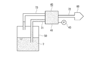
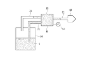
- Operation movement explanatory drawing explaining operation
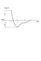
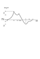
- the graph which shows the change of the system internal pressure at the time of operation
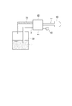
- movement explanatory drawing explaining operation movement of a compressed gas discharge
- movement explanatory drawing explaining operation movement of a compressed gas discharge
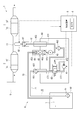
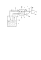
- FIG. 1 shows an overall configuration of an exhaust gas aftertreatment device 1 including a reducing agent supply device 4 of the first embodiment.
- the exhaust gas aftertreatment device 1 includes particulate matter (Particulate Matter; hereinafter referred to as “PM”) and nitrogen oxide (NOx) in exhaust gas flowing through an exhaust pipe 11 of a diesel engine (hereinafter referred to as “engine”) 10. ) Etc.
- PM particulate Matter
- NOx nitrogen oxide
- DPF diesel particulate filter
- SCR selective catalyst A reduction (Selective Catalytic Reduction; hereinafter referred to as “SCR”) device 3
- SCR selective Catalytic Reduction
- the DPF device 2 includes a diesel oxidation catalyst (Diesel Oxidation Catalyst; hereinafter referred to as “DOC”) 21 and a catalyzed soot filter (hereinafter referred to as “CSF”) 22.
- the DOC 21 is a catalyst that raises the exhaust gas temperature to a predetermined high temperature range by oxidizing and heat-generating dosing fuel supplied to the exhaust gas as necessary. By using this raised exhaust gas, PM deposited on the CSF 22 described later is self-combusted and incinerated and removed, and the CSF 22 is regenerated.
- the dosing fuel is, for example, the same light oil as the engine fuel, and is supplied into the exhaust gas by a dosing fuel injection device (not shown) provided in the exhaust pipe 11, and together with the exhaust gas It flows into the DPF device 2. Further, in the case of supplying dosing fuel into the engine cylinder, the dosing fuel is supplied by the fuel injection device for in-cylinder injection.
- the CSF 22 is a filter that collects PM in exhaust gas having a structure in which a large number of small holes are arranged.
- the small holes of the CSF 22 communicate from the inflow side to the outflow side, and the cross section is formed in a polygonal shape (for example, a hexagonal shape).
- the one opened at the inlet side and sealed at the outlet side and the one sealed at the inlet side and opened at the outlet side were alternately arranged and flowed from the former small hole. Exhaust gas passes through the boundary wall, escapes into the latter small hole, and flows downstream. And PM is collected by the boundary wall.
- the material of CSF22 consists of ceramics, such as cordierite and silicon carbide, or metals, such as stainless steel and aluminum, and is suitably determined according to a use. Note that an oxidation catalyst made of a material different from that of the DOC 21 may be coated on the inlet side of the CSF 22 with a wash coat or the like.
- the SCR device 3 includes an SCR 31 and an ammonia oxidation catalyst 32.
- the SCR 31 reduces and purifies nitrogen oxides (NO x ) in the exhaust gas by using ammonia obtained by decomposition of urea water injected into the exhaust gas from the reducing agent supply device 4 as a reducing agent.
- the ammonia oxidation catalyst 32 disposed on the downstream side of the SCR 31 oxidizes ammonia that has been unused in the SCR 31 to render it harmless, and further reduces harmful components in the exhaust gas.
- the SCR device 3 is provided with various sensors (not shown) such as a temperature sensor that measures the inlet temperature of the SCR device 3, a temperature sensor that measures the outlet temperature, and an ammonia sensor that measures the ammonia concentration.
- the measurement data of each of these sensors is output to the control device 5, and the control device 5 controls the reducing agent supply device 4 based on the measurement data to perform the ejection control of urea water.
- the reducing agent supply device 4 is a device that ejects urea water 7 as an aqueous reducing agent solution into the exhaust gas, and includes a pump unit 40 that pumps the urea water 7, a tank 50 that stores the urea water 7, and urea water. 7 is provided with an injection nozzle 60 that injects 7 into the exhaust pipe 11 and a reducing agent supply passage 70 through which urea water 7 supplied from the tank 50 to the injection nozzle 60 by the pump unit 40 flows.
- the pump unit 40 includes a pump 41 that pumps the urea water 7, a switching valve 42, a pressure gauge 43, a check valve 44, and an orifice 45. Further, the pump unit 40 includes three ports 451, 452, and 453.
- the port 451 is an inlet port of the pump unit 40, and the port 451 and the switching valve 42 are connected by a first passage 471.
- the port 452 is an outlet port of the pump unit 40, and the switching valve 42 and the port 452 are connected by a second passage 472.
- the port 453 is a return port for returning the urea water 7 to the tank 50, and the port 453 is connected to the third passage 473 branched from the second passage 472.
- the port 451 is provided with a screen filter 461 for pump inlet to prevent foreign matter from entering the pump 41.
- a filter 462 is provided in the middle of the second passage 472 to prevent foreign matters from flowing out.
- the port 453 is provided with a screen filter 463, a check valve 44, and an orifice 45.
- a pressure gauge 43 is disposed in the third passage 473. Since the third passage 473 communicates with the second passage 472, the pressure gauge 43 detects the system pressure P in the second passage 472 and the second reducing agent supply passage 72.
- the tank 50 and the port 451 are connected by a first reducing agent supply passage 71.
- the port 452 and the injection nozzle 60 are connected by a second reducing agent supply passage 72. Therefore, the first reducing agent supply passage 71 and the second reducing agent supply passage 72 constitute a reducing agent supply passage 70 for supplying urea water 7 as a reducing agent from the tank 50 to the injection nozzle 60.
- the port 453 and the tank 50 are connected by a bypass passage 73.
- the first reducing agent supply passage 71, the second reducing agent supply passage 72, and the bypass passage 73 are specifically configured by hoses.
- the end of the first reducing agent supply passage 71 on the tank 50 side is disposed near the bottom surface of the tank 50 in order to allow the urea water 7 to be sucked.
- a tank suction port strainer 75 is provided at the end of the first reducing agent supply passage 71 to prevent foreign matter from being sucked into the reducing agent supply passage 70.
- the end of the bypass passage 73 on the tank 50 side is disposed at a position higher than the liquid level of the urea water 7 in the tank 50.
- the tank 50 is provided with a breather or the like for maintaining the internal pressure at atmospheric pressure.
- the pump 41 is typically an electric pump, and the drive is controlled by the control device 5.
- the inlet side passage 411 and the outlet side passage 412 of the pump 41 are connected to the switching valve 42.
- the switching valve 42 is configured so that the urea water 7 pumped by the pump 41 flows in the forward flow direction from the tank 50 to the injection nozzle 60 and the reverse flow direction from the injection nozzle 60 to the tank 50 according to a control signal from the control device 5. And an electromagnetic switching valve. When the control signal is not output from the control device 5 and the solenoid is not energized, the switching valve 42 connects the first passage 471 to the inlet side passage 411 and the second passage 472 to the outlet side passage 412. In communication, the direction in which the urea water 7 flows is set as the forward flow direction.
- the pump 41 when the pump 41 is operated, the urea water 7 is sucked into the inlet side passage 411 from the first reducing agent supply passage 71 via the first passage 471, and the urea water 7 is drawn from the outlet side passage 412 via the second passage 472.
- the urea water 7 is discharged into the second reducing agent supply passage 72. Therefore, the pump 41 and the switching valve 42 set in the forward flow direction constitute the pressure feeding means of the present invention.
- the switching valve 42 communicates the first passage 471 to the outlet side passage 412 and the second passage 472 to the inlet side passage 411 when a control signal is output from the control device 5 and the solenoid is energized.
- the direction in which the urea water 7 flows is switched to the reverse flow direction.
- the sucking-back means of the present invention is constituted by the pump 41 and the switching valve 42 set in the reverse flow direction.
- a structure which switches the direction through which the urea water 7 flows it is not limited to what uses the switching valve 42 like this embodiment. For example, two pumps may be provided to share discharge and suck back.
- the discharge pump is operated, the suction pump is stopped and the urea water 7 is discharged in the forward flow direction, the discharge pump is stopped, and the suction pump is operated to move the urea water 7 in the reverse flow direction. Just suck it back.
- the injection nozzle 60 uses an electromagnet 65 and a spring 66 with respect to a valve seat 64 communicating with the injection hole 63.
- the needle valve 62 is arranged in the case 61 so as to be movable in the axial direction.
- the valve opening and closing states are controlled by advancing and retreating. That is, when a control signal is output from the control device 5 and the electromagnet 65 is energized, the needle valve 62 is separated from the valve seat 64 by the magnetic force generated by the electromagnet 65, and the injection nozzle 60 injects the urea water 7 from the injection hole 63. Possible valve open state.
- the needle valve 62 contacts the valve seat 64 due to the pressure of the spring 66 and the urea water 7, and the injection nozzle 60 has the injection hole 63.
- the valve is in a closed state in which urea water cannot be injected.
- the urea water 7 injected into the exhaust pipe 11 from the injection hole 63 when the injection nozzle 60 is in the valve open state is thermally decomposed into ammonia by the heat of the exhaust gas, and the SCR 31 reduces and purifies nitrogen oxides.
- a screen filter 67 is provided between the injection nozzle 60 and the second reducing agent supply passage 72 as shown in FIG.
- the control device 5 is constituted by a microcomputer, and is configured to be able to read the sensor signals of the pressure sensors and the temperature sensors provided in the DPF device 2 and the SCR device 3 in addition to reading the detection signal of the pressure gauge 43. Yes. Further, various sensor signals such as a rotation speed sensor for detecting the rotation speed of the engine 10, a vehicle speed sensor for detecting the vehicle speed of the vehicle, an accelerator sensor for detecting the operation amount of the accelerator pedal, and a brake sensor for detecting the operation amount of the brake pedal are also provided. It is configured to be readable. Further, the control device 5 is provided with a RAM (Random Access Memory) (not shown) for storing calculation results and detection results at each unit. Further, the control device 5 has a built-in timer 6 for measuring time.
- RAM Random Access Memory
- the control device 5 outputs control signals to the pump 41, the switching valve 42, and the injection nozzle 60 to control these operations. That is, the control device 5 performs feedback control of the pump 41 based on the pressure value detected by the pressure gauge 43 during operation of the engine 10, so that the pressure in the second passage 472 and the second reducing agent supply passage 72 is controlled. Is maintained at a predetermined value. Specifically, the control device 5 discharges the pump 41 when the pressure value detected by the pressure gauge 43 becomes higher than a predetermined value when the urea water 7 is being pumped by the pump 41. When the pressure is reduced and the pressure value becomes lower than the predetermined value, the pressure in the second passage 472 and the second reducing agent supply passage 72 is maintained at the predetermined value by increasing the discharge amount of the pump 41.
- control device 5 controls the driving of the injection nozzle 60 based on the rotational speed of the engine 10 and the sensor value of the NO X sensor provided on the exhaust downstream side of the SCR 31. Furthermore, the control device 5 instructs the execution of the process of removing the urea water 7 from the injection nozzle 60 when the engine 10 is stopped. In this case, as will be described later, the control device 5 operates the pump 41, the switching valve 42, and the injection nozzle 60 at a predetermined timing to remove the urea water 7 from the injection nozzle 60.
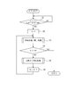
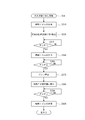
- control device 5 determines whether the engine starter key is turned off while the engine 10 is operating (step S ⁇ b> 1). When it is determined NO in step S1, the control device 5 continues the control of operating the reducing agent supply device 4 and injecting the urea water 7 into the exhaust pipe 11 because the engine 10 is operating. That is, during operation of the engine 10, as shown in FIG.
- the control device 5 controls the pump 41 in the pump unit 40 based on the pressure value detected by the pressure gauge 43, so that urea in the tank 50 is Water 7 is pumped to the jet nozzle 60 side. Part of the urea water 7 returns to the tank 50 through the bypass passage 73, and the pressure in the second reducing agent supply passage 72 is maintained at a predetermined value. Further, the control device 5 controls the valve opening time and the number of times of the injection nozzle 60 based on measured values of a temperature sensor, an ammonia sensor and the like provided in the SCR device 3, and the urea water 7 into the exhaust pipe 11 is controlled. Control the injection.
- the control device 5 determines YES in step S ⁇ b> 1, and residual urea water in the injection nozzle 60 after step S ⁇ b> 2. The removal process is performed. At this time, the control device 5 continues to drive the pump 41 even after YES is determined in step S1 and the engine 10 is stopped. Since the timing at which the engine 10 is stopped depends on the operation of the operator, the injection nozzle 60 is opened immediately before the engine 10 is stopped and the urea water 7 is injected, and the injection nozzle 60 is closed and the urea is injected. There are both cases where the water 7 is not jetted.
- step S1 the control device 5 sets a variable N indicating the number of processes to an initial value “1” (step S2).
- the control device 5 executes urea water sucking back processing (step S3) described later.
- step S4 the control device 5 determines whether or not the variable N is larger than a preset set value N0 (step S4).
- the set value N0 is a set value of the number of executions of the compressed gas discharge process S5, as will be described later. If the determination is NO in step S4, the control device 5 executes a compressed gas discharge process (step S5) described later, and adds “1” to the variable N (step S6).
- step S6 the control device 5 executes the urea water sucking back process S3 again. Then, the processes in steps S5, S6, and S3 are repeatedly executed until YES is determined in step S4.
- step S4 that is, when the compressed gas discharge process S5 is executed the number of times of the set value N0, the control device 5 ends the control of the reducing agent supply device 4 when the engine is stopped. Note that when the control is finished by repeating Steps S3 to S6, the urea water sucking-back process S3 is executed at the beginning and the end, so it is executed once more than the compressed gas releasing process S5.
- step S3 Details of the urea water suck-back process S3 will be described based on the flowchart of FIG. 4, the operation explanatory diagrams of FIGS. 6 to 10, and the graph showing the pressure change of FIG.
- the control device 5 controls the pump 41 based on the system pressure P detected by the pressure gauge 43, so that the second detected by the pressure gauge 43.
- the system pressure P in the passage 472 and the second reducing agent supply passage 72 is maintained at a predetermined positive pressure (predetermined value).
- predetermined positive pressure predetermined value
- the injection nozzle 60 may be in a valve-closed state depending on the timing of turning off the engine starter key. In this case, the valve-closed state is maintained. That is, if the valve 5 is in the open state in which the electromagnet 65 of the injection nozzle 60 is energized, the control device 5 cuts off the energization to the electromagnet 65 and closes the valve in step S31. Further, if the valve 5 is not energized to the electromagnet 65 of the injection nozzle 60, the control device 5 maintains the state where the electromagnet 65 is not energized as it is, that is, the valve closed state, even in step S31. In addition, before performing step S31, the opening / closing state of the injection nozzle 60 may be determined, and the process of closing the valve of the injection nozzle 60 may be executed only when the injection nozzle 60 is in the valve open state.
- control device 5 starts time measurement by the timer 6 (step S32).
- step S33 the control device 5 energizes the solenoid of the switching valve 42 to switch the switching valve 42 to the reverse flow side (step S33).
- the pump 41 continues to operate, and the sucking-back means is activated when the switching valve 42 is switched to the reverse flow side.
- the time t measured by the timer 6 substantially switches the switching valve 42 to the reverse flow side and starts the operation of the sucking-back means. Elapsed time t from time T0.
- the urea water 7 in the injection nozzle 60 and the second reducing agent supply passage 72 is changed to the first by the operation of the pump 41 functioning as the suck back means. And then sucked back through the reducing agent supply passage 71 toward the tank 50 side. For this reason, as shown between the time T0 and the time T1 in FIG. 11, the system pressure P in the second reducing agent supply passage 72 gradually decreases. Further, since the bypass passage 73 is blocked by the check valve 44 while the urea water 7 is flowing backward, the flow of the urea water 7 in the bypass passage 73 is stopped.
- the backflow of the urea water 7 continues to some extent, but since the injection nozzle 60 is in a closed state, the first reduction occurs when the negative pressure at the suction capacity limit of the pump 41 is reached.
- the back flow of the urea water 7 in the agent supply passage 71 and the second reducing agent supply passage 72 is also stopped.
- the control device 5 determines whether or not the time t (elapsed time from the time T0) measured by the internal timer 6 starting from the time T0 is equal to or longer than the first set time T1 set in advance (step S34).
- the first set time T1 is the second reducing agent after the switching valve 42 is switched to the reverse flow side in step S33 and the urea water 7 in the second reducing agent supply passage 72 starts to flow backward to the tank 50 side. This is the time until the pressure in the supply passage 72 reaches a specified negative pressure (first pressure value P1).
- the first set time T1 can be obtained by performing an experiment in advance, or the second reducing agent supply passage 72, the second passage 472, and the urea water 7 are caused to flow backward from the injection nozzle 60 to the pump 41 in the backflow state. It can also be set based on the volume of the inlet side passage 411 and the volume of the pump 41.
- the control device 5 continues to operate the pump 41 in the backflow state with the injection nozzle 60 closed, and the urea water The sucking back operation of No. 7 is continued.
- step S34 the control apparatus 5 will supply with electricity to the electromagnet 65, and will open the valve
- the pressure in the second reducing agent supply passage 72 is a predetermined negative pressure P1
- the valve of the injection nozzle 60 is opened, as shown in FIG.
- the urea water 7 in the agent supply passage 72 is sucked back to the tank 50 side, and the gas flowing in the exhaust pipe 11 flows into the second reducing agent supply passage 72 from the injection hole 63 of the injection nozzle 60.
- the system pressure P of the second reducing agent supply passage 72 gradually increases.
- the second time when the valve of the injection nozzle 60 is opened in order to open the valve of the injection nozzle 60 in step S35 after the pressure in the second reducing agent supply passage 72 is made negative in steps S33 and S34, the second time when the valve of the injection nozzle 60 is opened.
- the urea water 7 in the reducing agent supply passage 72 can be prevented from being injected into the exhaust pipe 11, and the gas in the exhaust pipe 11 can be reliably introduced into the injection nozzle 60 and the second reducing agent supply passage 72.
- the control apparatus 5 determines whether the time t which started the measurement by the said step S32 became more than the 2nd preset time T2 set beforehand (step S36).
- the second set time T2 is within the reducing agent supply passage 70 (first reducing agent supply passage 71, second reducing agent supply passage 72) and in the pump unit 40 (second passage). 472, the first passage 471, the inlet-side passage 411, and the outlet-side passage 412) are elapsed times from the time T0 until the gas flowing in from the injection nozzle 60 is replaced.
- the second set time T2 can also be obtained by experimenting in advance, or can be set based on the volumes of the reducing agent supply passage 70 and the pump unit 40.
- the elapsed time t from when the gas is generated to when the generation of bubbles is confirmed may be set to the second set time T2.
- the lengths of the hoses used as the first reducing agent supply passage 71 and the second reducing agent supply passage 72 may be different.
- the second set time T2 is set to the length of the hose in the first reducing agent supply passage 71 and the second reducing agent supply passage 72. It can be easily set according to the situation. That is, if the length of the hose in each of the reducing agent supply passages 71 and 72 is increased, the second set time T2 may be set longer.
- the control device 5 continues the suction operation of the pump 41 with the injection nozzle 60 opened.
- control device 5 determines YES in step S36, it stops the pump 41 (step S37).
- the system pressure P at this time is a predetermined negative pressure (second pressure value P2) as shown in FIG.
- the second pressure value P2 is a pressure higher than the first pressure value P1.
- the control device 5 switches the switching valve 42 to the forward flow side (step S38).
- the system pressure P in the second reducing agent supply passage 72 gradually approaches atmospheric pressure.
- the control device 5 determines whether or not the elapsed time t is equal to or longer than a preset third set time T3 (step S39).
- the third set time T3 is the time from when the time measurement is started in step S32 until the system pressure P in the second reducing agent supply passage 72 reaches the third pressure value P3.
- the third pressure value P3 is substantially atmospheric pressure.
- the third set time T3 can also be obtained by experimenting in advance, and the total area of the injection holes of the injection nozzle 60 and the reducing agent supply passage 70 (the first reducing agent supply passage 71, the second reducing agent supply). It can be set based on the passage 72) and the total volume of the pump unit 40. While it is determined NO in step S39, that is, when the measurement time t is less than the third set time T3, the control device 5 continues the state where the injection nozzle 60 is opened and the state where the pump 41 is stopped. .
- step S40 the control apparatus 5 will close the valve
- step S40 the urea water sucking back process S3 of the second reducing agent supply passage 72 and the injection nozzle 60 is completed.
- the pump unit 40 is almost the entire length of the reducing agent supply passage 70 (the first reducing agent supply passage 71 and the second reducing agent supply passage 72).
- the almost entire volume of the injection nozzle 60 and the almost entire volume of the injection nozzle 60 are replaced with gas, and the bypass passage 73 is almost filled with urea water.
- the injection nozzle 60 is maintained in the closed state in step S40.
- Step S4 determines whether or not a variable N indicating the number of times of execution of the compressed gas discharge process S5 is larger than a preset set value N0 ( Step S4).
- the control device 5 determines NO in step S4
- the control device 5 performs the compressed gas discharge processing S5.
- the control device 5 determines YES in step S4 it ends the control of FIG. For this reason, for example, if the set value N0 is “2”, the control device 5 ends the control when the variable N becomes 3 when the compressed gas discharge process S5 is performed twice.
- the set value N0 may be set according to the volume of the second reducing agent supply passage 72 or the like. That is, the amount of gas discharged in the compressed gas release process S5 differs depending on the volume of the second reducing agent supply passage 72. The larger the volume of the second reducing agent supply passage 72, the larger the amount of gas released. To do.
- the purpose of the compressed gas discharge process S5 is to discharge a small amount of urea water remaining in the injection nozzle 60 to the outside of the injection nozzle 60. Therefore, it is necessary to release a certain amount of gas. For this reason, when the volume of the second reducing agent supply passage 72 is small and the amount of gas released is small, it is necessary to repeat the compressed gas release processing S5 several times, and the number of executions is set at the set value N0. Yes.
- the remaining volume portion of the first reducing agent supply passage 71, almost the entire volume of the pump unit 40, and almost the entire volume of the second reducing agent supply passage 72 and the injection nozzle 60 are replaced with gas.
- the bypass passage 73 is substantially filled with the urea water 7 although it is affected by the sealing performance of the check valve 44.
- the control apparatus 5 starts time measurement again using the said timer 6, as shown in FIG. 5 (step S51). That is, the measurement time t is reset to 0, and the time measurement by the timer 6 is restarted.
- the control device 5 starts the pump 41 with the injection nozzle 60 closed (step S52). Then, as shown in FIG. 13, the urea water 7 flows into the first reducing agent supply passage 71 from the tank 50. Further, the pressure applied to the check valve 44 also increases, and the gas in the first reducing agent supply passage 71 and the pump unit 40 is pumped to the bypass passage 73, the second reducing agent supply passage 72, and the injection nozzle 60. The For this reason, as shown in FIG. 17, the system pressure P in the second reducing agent supply passage 72 rises from the atmospheric pressure P3. Further, when the operation of the pump 41 is continued, as shown in FIG.
- the urea water 7 sucked from the tank 50 into the first reducing agent supply passage 71 flows into the bypass passage 73 and the second reducing agent supply passage 72. Flow into. Since the injection nozzle 60 is in a closed state, when the urea water 7 flows into the second reducing agent supply passage 72, the gas in the second reducing agent supply passage 72 and the injection nozzle 60 is compressed, and the system pressure P Will rise further. The system pressure P is increased up to about 90 ⁇ 10 4 Pa (9 bar), and the gas volume is reduced to about 1/9.
- the control device 5 determines whether or not the time t when the measurement time t is reset to 0 in step S51 and the measurement is started is equal to or greater than a preset fourth set time T4 (step S53).
- the time t at which measurement is started in step S51 is an elapsed time t after the pump 41 that is the pressure feeding means is operated.
- the system pressure P in the second reducing agent supply passage 72 becomes the fourth pressure value P4 (for example, 90 ⁇ 10 4 Pa) after the time measurement is started in step S51. It is time to become. While it is determined NO in step S53, that is, when the measurement time t is less than the fourth set time T4, the control device 5 continues the operation of the pump 41 with the injection nozzle 60 closed.
- step S53 the control apparatus 5 will open the valve
- the pump 41 is operated to supply the urea water 7 into the second reducing agent supply passage 72 to compress the gas, so that the urea water 7 remaining in the injection nozzle 60 is blown off at a high pressure P4.
- the suction pressure in the urea water suck-back process S3 is about 9.8 ⁇ 10 4 Pa ( ⁇ 1 kgf / cm 2 ) or less, but the blow-off pressure due to the compressed gas discharge in step S54 is about 40-50 ⁇ . Since the pressure can be increased to about 10 4 Pa ( ⁇ 4 to 5 kgf / cm 2 ), the compressed gas releasing process S5 can effectively discharge the remaining urea water compared to the urea water sucking back process S3.
- step S54 When the valve of the injection nozzle 60 is opened in step S54, the system pressure P in the second reducing agent supply passage 72 decreases as shown in FIG. Further, since a part of the gas compressed in the second reducing agent supply passage 72 and the injection nozzle 60 is discharged from the injection hole 63, the second reducing agent supply passage 72 is shown in FIG. The urea water inside moves to the injection nozzle 60 side.
- the control device 5 determines whether or not the time t at which measurement is started in step S51 is equal to or longer than a preset fifth set time T5 (step S55).
- the fifth set time T5 is an elapsed time after the measurement time t is reset to 0 in step S51 and measurement is started, and the injection nozzle 60 is opened by opening the valve of the injection nozzle 60 in step S54.
- the urea water 7 in the second reducing agent supply passage 72 that has moved to the side is set to be less than the time for reaching the injection nozzle 60. That is, if the time for the urea water 7 to reach the injection nozzle 60 after starting the time measurement in step S51 is Tmax, the fifth set time T5 is less than Tmax.
- the fifth set time T5 can be obtained by experimenting in advance, or can be set based on the volume of the second reducing agent supply passage 72 and the total area of the injection holes 63 of the injection nozzle 60. As described above, in the present embodiment, control is performed by determining whether or not the elapsed time t has exceeded the preset set times T1 to T5 in steps S34, S36, S39, S53, and S55. For this reason, the opening / closing timing of the injection nozzle 60, the stop timing of the pump 41, and the like can be set by feedforward control, and the control device 5 determines the type and number of sensors compared to the case of controlling based on the detection values of various sensors. The elapsed time t can be easily controlled simply by comparing the elapsed time t with the set times T1 to T5.
- step S55 determines whether or not the measurement time t is less than the time Tmax (step S57).
- the control device 5 determines NO in step S55 and opens the injection nozzle 60 while determining YES in step S57, that is, when the measurement time t is less than the fifth set time T5. Continue state. And the control apparatus 5 will determine with YES by step S55, if the measurement time t becomes more than 5th setting time T5.
- step S55 the control apparatus 5 will close the valve
- the valve 60 is closed and the compressed gas discharge process S5 is completed. For this reason, when the urea water 7 has moved into the injection nozzle 60, it is possible to prevent the urea water 7 from being injected into the exhaust pipe 11 by continuing the valve opening state of the injection nozzle 60.
- the control device 5 performs a process of updating by adding 1 to the variable N as shown in FIG. 3 (step S6). Then, the urea water sucking back process S3 is executed again. That is, at the end of the compressed gas release process S5, as shown in FIG. 16, the substantially entire length of the first reducing agent supply passage 71, the substantially entire volume of the pump unit 40, and the bypass passage 73 are almost filled with the urea water 7, The urea water 7 also remains in the second reducing agent supply passage 72. Further, the system pressure P is also higher than the atmospheric pressure as shown in FIG. For this reason, by performing the urea water sucking-back process S3 again, as shown in FIG.
- the pump unit 40, the first reducing agent supply passage 71, and the second reducing agent supply passage 72 at the end of the control. Can be replaced by gas and reduced to atmospheric pressure.
- the system pressure P increases during the period from T5 to T6 in FIG. 17 after the valve of the injection nozzle 60 is closed in step S56 and then until the switching valve 42 is switched to the reverse flow side in step S33. This is because the operation of the pump 41 continues in a state where the valve of the nozzle 60 is closed.
- the control device 5 ends the compressed gas discharge process S5 shown in FIG. 3 at T6 of FIG. 17, starts the urea water suction process S3, and resets the measurement time t to 0 in step S32. For this reason, the control apparatus 5 sets the timing of time T6 as time T0, and starts measurement of time t again.
- the control device 5 controls the driving of the pump 41, the switching valve 42, and the injection nozzle 60 to execute the compressed gas release process S5, and the second reducing agent supply passage 72 and
- the urea water 7 remaining in the injection nozzle 60 can be discharged into the exhaust pipe 11. .
- This discharge of compressed gas can discharge the urea water 7 at a higher pressure than the case where the urea water 7 remaining in the injection nozzle 60 is sucked by the urea water sucking back process S3, and the urea water 7 is more effectively discharged.
- steps S33A, S35A, S37A, S38A, and S40A are the same processes as steps S33, S35, S37, S38, and S40 of the urea water suction process S3 of the first embodiment. Omitted. Further, in the urea water sucking back process S3A, the time t is not measured, so the time measurement starting process in step S32 of the urea water sucking back process S3 is not executed.
- step S34A the control device 5 determines whether or not the system pressure P measured by the pressure gauge 43 has become equal to or lower than a preset first pressure value P1. That is, in the second embodiment, similarly to the first embodiment, when the switching valve 42 is switched to the reverse flow side in step S33A and the urea water in the reducing agent supply passage 70 is sucked back to the tank 50 side, FIG. As shown, the internal pressure P decreases from positive pressure to negative pressure. When the system pressure P detected by the pressure gauge 43 decreases to the first pressure value P1, the control device 5 determines YES in Step S34A and opens the valve of the injection nozzle 60 (Step S35A).
- step S35A When the valve of the injection nozzle 60 is opened in step S35A, gas flows from the exhaust pipe 11 into the injection nozzle 60 and the reducing agent supply passage 70, and the system pressure P gradually increases as shown in FIG.
- the control device 5 determines YES in step S36A and stops the pump 41 (step S37A).
- both the first pressure value P1 and the second pressure value P2 are negative pressures, and the second pressure value P2 is a pressure higher than the first pressure value P1.
- the control device 5 returns the switching valve 42 to the forward flow side after the pump 41 is stopped (step S38A). At this time, since the injection nozzle 60 is maintained in the open state and the tank 50 is also at atmospheric pressure, the system pressure P gradually increases and returns to atmospheric pressure as shown in FIG. When the system pressure P detected by the pressure gauge 43 rises to the third pressure value P3, the control device 5 determines YES in step S39A and closes the valve of the injection nozzle 60 (step S40A). The third pressure value P3 is higher than the second pressure value P2, and is substantially atmospheric pressure. Thus, the urea water sucking back process S3A is completed.
- steps S52A to S56A shown in FIG. 19 are executed. Of these steps, steps S52A, S54A, and S56A are the same processes as steps S52, S54, and S56 of the compressed gas release process S5 of the first embodiment, and a description thereof will be omitted. Also, in the compressed gas release process S5, the time t is not measured, so the time measurement start process in step S51 of the compressed gas release process S5 is not executed.
- step S53A the controller 5 determines whether or not the system pressure P measured by the pressure gauge 43 is equal to or higher than a preset fourth pressure value P4. That is, in the second embodiment, as in the first embodiment, when the pump 41 is started with the injection nozzle 60 closed in step S52A, the system pressure P increases from the atmospheric pressure as shown in FIG. To do. At this time, as in FIGS. 13 and 14 of the first embodiment, the urea water 7 flows from the tank 50 into the first reducing agent supply passage 71, and in the first reducing agent supply passage 71 and the pump unit 40. Is fed to the bypass passage 73, the second reducing agent supply passage 72, and the injection nozzle 60 by pressure.
- step S54A the control apparatus 5 will open the valve
- the control device 5 determines whether or not the system pressure P detected by the pressure gauge 43 is equal to or lower than the fifth pressure value P5 (step S55A).
- the valve of the injection nozzle 60 is opened in step S54A, the system pressure P decreases as in the first embodiment.
- the fifth pressure value P5 is set to a pressure at which the urea water 7 in the second reducing agent supply passage 72 does not reach the injection nozzle 60.
- the fifth pressure value P5 is a pressure value lower than the fourth pressure value P4 and higher than the third pressure value P3. Therefore, the control device 5 continues the gas release by opening the valve of the injection nozzle 60 while it is determined as YES in Step S55A.
- step S56A the control apparatus 5 determines NO in step S55A, it closes the valve of the injection nozzle 60 (step S56A). Thereby, similarly to FIG. 16 of 1st Embodiment, the movement to the injection nozzle 60 side of the urea water 7 in the 2nd reducing agent supply path 72 stops. In addition, since the operation of the pump 41 is continued with the valve of the injection nozzle 60 closed, as shown in FIG. 17 of the first embodiment, the system pressure in the second reducing agent supply passage 72 is shown. P rises. Thus, the compressed gas release process S5A is completed.
- the discharge amount per hour of the pump 41 is Q P
- the amount flowing into the second reducing agent supply passage 72 out of the amount discharged from the pump 41 is Q INJ
- the discharge amount from the pump 41 Q BP is the amount flowing into the bypass passage 73
- V F is the spatial volume in the pump unit 40
- L is the length of the second reducing agent supply passage 72 between the injection nozzle 60 and the pump 41
- the inner diameter of the reducing agent supply passage 72 of d is d
- the internal space volume of the injection nozzle 60 is V INJ .
- the space volume V F in the pump unit 40 is mainly the space volume in which the filter 462 is attached.
- Equation (4) R is a gas constant.
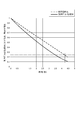
- the value (about 0.24) indicated by the alternate long and short dash line in FIG. 21 indicates a state in which the remaining space is only in the injection nozzle 60. Therefore, it is possible to grasp the ratio of the in-system pressure P to the initial value (fourth pressure value P4) when the remaining space ratio decreases to the level of the one-dot chain line. For this reason, in the case of FIG. 21, if the valve of the injection nozzle 60 is closed before the ratio of the system pressure P to the initial value drops to about 0.13, the urea water 7 reaches the injection nozzle 60. Can be prevented.
- the fifth pressure value P5 is set to a value at which the fifth pressure value P5 / the fourth pressure value P4 is 0.13 or more, so that the urea water 7 reaches the injection nozzle 60 before the urea water 7 reaches the injection nozzle 60.
- the valve can be closed.
- the opening / closing timing and the like of the injection nozzle 60 can be controlled based on the system pressure P measured by the pressure gauge 43. Further, the first pressure value P1 to the fifth pressure value P5 which are threshold values to be compared with the system pressure P can be obtained by the simulation as described above. Accordingly, preparation work is facilitated as compared with the case where the opening / closing timing of the injection nozzle 60 is set by conducting an experiment or the like in advance. In particular, even when the lengths of the hoses constituting the first reducing agent supply passage 71 and the second reducing agent supply passage 72 are different, it is not necessary to conduct an experiment individually, so that the preparation work is facilitated.
- the present invention is not limited to the above-described embodiments, and modifications, improvements, and the like within the scope that can achieve the object of the present invention are included in the present invention.
- sensors that detect the presence or absence of the urea water 7 are provided at a plurality of locations, and the control device 5 determines the injection nozzle 60 and the pump 41 according to the movement position of the urea water 7 detected by the sensor.
- the switching valve 42 may be controlled.
- the first pressure value P1 to the fifth pressure value P5 are calculated and calculated based on simulation, but may be obtained by performing an experiment. Moreover, in each said embodiment, although control was complete
Landscapes
- Engineering & Computer Science (AREA)
- Chemical & Material Sciences (AREA)
- Combustion & Propulsion (AREA)
- Mechanical Engineering (AREA)
- General Engineering & Computer Science (AREA)
- Chemical Kinetics & Catalysis (AREA)
- Health & Medical Sciences (AREA)
- Toxicology (AREA)
- Exhaust Gas After Treatment (AREA)
- Exhaust Gas Treatment By Means Of Catalyst (AREA)
Abstract
Description
この尿素SCRシステムは、還元剤としての尿素水を貯蔵するタンクと、タンク内から汲み上げた還元剤を圧送する圧送ポンプと、圧送される前記還元剤を供給する還元剤供給通路と、前記還元剤を還元剤供給通路から排気管内に供給する還元剤噴射ノズルとを備えて構成される。
ここで、尿素SCRシステムにおいて、尿素水を噴射する装置には、圧縮空気を利用するエアアシスト方式と、圧縮空気を利用しないエアレス方式とがある。エアレス方式は尿素水を昇圧させるため、ノズルの開口を開閉する弁を設けている。このため、弁の開閉時間や回数を制御することで、尿素水の噴射量を高精度に制御できる。
このため、エンジンの停止後に、圧送ポンプが、還元剤供給通路および還元剤噴射ノズルに対して、さらに尿素水溶水を充填した後、吸引して回収することで還元剤噴射ノズルの熱を回収し、噴射ノズル内に残留した尿素水が高温になるのを避けることで尿素水の固化を未然に防止する還元剤供給装置が知られている(例えば、特許文献1参照)。
そして、尿素水が残留した状態で放置すると、前述のとおり、水分が蒸発して尿素が析出し、噴射ノズル内の流路を閉塞したり、弁の動きに支障が生じ、エンジンの運転を再開した時に、尿素水噴射不能状態になるという問題がある。
次に、噴射ノズルを開弁した状態で前記吸い戻し手段を作動して、前記噴射ノズルおよび前記還元剤供給通路内に前記排気管内のガスを導入する。その後、噴射ノズルを閉弁して圧送手段で還元剤供給通路内に還元剤を供給する。このため、還元剤供給通路内に導入された前記ガスは、還元剤供給通路に供給された還元剤と噴射ノズル間に閉じ込められ、還元剤が圧送されるに従って圧縮される。
その後、噴射ノズルを開弁すると、前記圧縮されたガスが噴射ノズルを通して前記排気管に放出される。この圧縮ガスによって噴射ノズルに加わる圧力は、前記吸い戻し手段で噴射ノズル内の還元剤を吸い戻す場合に比べて容易に高くできる。したがって、吸い戻し時に前記噴射ノズル内に還元剤が残留していても、前記圧縮ガスの放出によって残留した還元剤を吹き飛ばして除去することができる。
このため、噴射ノズル内に還元剤が残留することを抑制でき、残留した還元剤が結晶化することも防止できる。したがって、噴射ノズル内の流路を結晶が閉塞したり、結晶によって弁の動きに支障が生じることも防止でき、エンジンの運転を再開した時に、還元剤を排気管内に確実に噴射できる。
さらに、圧縮ガスを放出した後、制御装置は、還元剤供給通路内の還元剤が噴射ノズルに到達する前に噴射ノズルを閉弁しているので、還元剤が再度噴射ノズルに到達することも防止できる。したがって、噴射ノズル内に残留する還元剤が増えることはなく、仮に1回目の圧縮ガス放出処理では残留した還元剤を除去できない場合でも、圧縮ガス放出処理を複数回繰り返すことで、噴射ノズル内の還元剤を確実に除去できる。
本発明においても、前記還元剤供給装置と同じ作用効果を奏することができる。
[第1実施形態]
[排気ガス後処理装置の全体構成]
図1は第1実施形態の還元剤供給装置4を含む排気ガス後処理装置1の全体構成を示す。排気ガス後処理装置1は、ディーゼルエンジン(以下「エンジン」と記す)10の排気管11内を流れる排気ガス中の粒子状物質(Particulate Matter;以下「PM」と記す)や窒素酸化物(NOx)等の残留物質の捕集や還元などの処理を行って排気ガスを浄化する装置であり、ディーゼル・パーティキュレート・フィルタ(Diesel particulate filter;以下「DPF」と記す)装置2と、選択的触媒還元(Selective Catalytic Reduction;以下「SCR」と記す)装置3と、還元剤供給装置4と、制御装置5とを備える。
DPF装置2は、ディーゼル酸化触媒(Diesel Oxidation Catalyst;以下「DOC」と記す)21と、触媒化スートフィルタ(Catalyzed Soot Filter;以下「CSF」と記す)22とを備えている。
DOC21は、排気ガス中に必要に応じて供給されるドージング燃料を酸化、発熱させて、排気ガス温度を所定の高温域まで上昇させる触媒である。この上昇した排気ガスを利用することで、後述するCSF22に堆積したPMを自己燃焼させて焼却除去し、CSF22を再生させる。
ドージング燃料は、内燃機関がディーゼルエンジンの場合では、例えばエンジン燃料と同じ軽油であり、排気管11に設けられたドージング用の燃料噴射装置(図示略)により排気ガス中に供給され、排気ガスと共にDPF装置2内に流入する。また、ドージング用の燃料をエンジンシリンダ内に供給する場合では、エンジンシリンダ内噴射用の燃料噴射装置によりドージング用の燃料を供給することになる。
SCR装置3は、SCR31と、アンモニア酸化触媒32とを備える。
SCR31は、還元剤供給装置4から排気ガス中に噴射される尿素水の分解で得られるアンモニアを還元剤とすることで、排気ガス中の窒素酸化物(NOx)を還元浄化するものである。
SCR31の下流側に配置されるアンモニア酸化触媒32は、SCR31で未使用とされたアンモニアを酸化処理して無害化するものであり、排気ガス中の有害成分をより低減する。
なお、SCR装置3には、SCR装置3の入口温度を測定する温度センサ、出口温度を測定する温度センサ、アンモニア濃度を測定するアンモニアセンサ等の図示略の各種センサが設けられる。
これらの各センサの測定データは、制御装置5に出力され、制御装置5は、前記測定データに基づいて還元剤供給装置4を制御して尿素水の噴出制御などを行う。
還元剤供給装置4は、排気ガス中に還元剤水溶液としての尿素水7を噴出する装置であり、尿素水7を圧送するポンプユニット40と、尿素水7が貯蔵されるタンク50と、尿素水7を排気管11内に噴射する噴射ノズル60と、ポンプユニット40によってタンク50から噴射ノズル60に供給される尿素水7が流れる還元剤供給通路70とを備える。
ポンプユニット40は、尿素水7を圧送するポンプ41と、切換弁42と、圧力計43と、逆止弁44と、オリフィス45とを備える。さらに、ポンプユニット40は,3つのポート451、452、453を備える。
ポート451は、ポンプユニット40の入口ポートであり、ポート451および切換弁42間は第1通路471で接続されている。ポート452は、ポンプユニット40の出口ポートであり、切換弁42およびポート452間は第2通路472で接続されている。ポート453は、尿素水7をタンク50に還流するためのリターンポートであり、ポート453は第2通路472から分岐された第3通路473に接続されている。
ポート451には、ポンプ入口用のスクリーンフィルター461が設けられ、ポンプ41に異物が侵入することを防止している。第2通路472の途中には、フィルター462が設けられ、異物が流出することを防止している。
ポート453には、スクリーンフィルター463と、逆止弁44と、オリフィス45とが設けられている。第3通路473には圧力計43が配置されている。第3通路473は第2通路472に連通しているので、圧力計43は、第2通路472、第2の還元剤供給通路72の系内圧力Pを検出する。
タンク50およびポート451間は、第1の還元剤供給通路71で接続されている。ポート452および噴射ノズル60間は、第2の還元剤供給通路72で接続されている。したがって、第1の還元剤供給通路71および第2の還元剤供給通路72で、タンク50から噴射ノズル60に還元剤である尿素水7を供給する還元剤供給通路70が構成される。
また、ポート453およびタンク50間はバイパス通路73で接続されている。
そして、第1の還元剤供給通路71、第2の還元剤供給通路72、バイパス通路73は、具体的にはホースで構成されている。
バイパス通路73のタンク50側の端部は、タンク50内の尿素水7の液面よりも高い位置に配置されている。
さらに、タンク50には、内部の圧力を大気圧に維持するためのブリーザー等が設けられている。
ポンプ41は、代表的には電動式ポンプが用いられ、制御装置5によって駆動が制御される。このポンプ41の入口側通路411および出口側通路412は、切換弁42に接続されている。
切換弁42は、制御装置5からの制御信号によって、ポンプ41によって圧送される尿素水7が流れる方向を、タンク50から噴射ノズル60に向かう順流方向と、噴射ノズル60からタンク50に向かう逆流方向とに切り換える電磁切換弁である。
切換弁42は、制御装置5から制御信号が出力されておらず、ソレノイドに通電されていない場合は、第1通路471を入口側通路411に連通し、第2通路472を出口側通路412に連通して、尿素水7が流れる方向を順流方向に設定する。この場合、ポンプ41が作動すると、第1の還元剤供給通路71から第1通路471を介して入口側通路411に尿素水7が吸い込まれ、出口側通路412から第2通路472を介して第2の還元剤供給通路72に尿素水7が吐出される。したがって、ポンプ41および順流方向に設定された切換弁42によって、本発明の圧送手段が構成される。
一方、切換弁42は、制御装置5から制御信号が出力されてソレノイドに通電されていると、第1通路471を出口側通路412に連通し、第2通路472を入口側通路411に連通して、尿素水7が流れる方向を逆流方向に切り換える。この場合、ポンプ41が作動すると、第2の還元剤供給通路72から第2通路472を介して入口側通路411に尿素水7が吸い込まれ、出口側通路412から第1通路471および第1の還元剤供給通路71を介してタンク50側に尿素水7が戻される。したがって、ポンプ41および逆流方向に設定された切換弁42によって、本発明の吸い戻し手段が構成される。
なお、尿素水7が流れる方向を切り換える構成としては、本実施形態のような切換弁42を用いるものに限定されない。例えば、2つのポンプを設け、吐出と吸い戻しとを分担させてもよい。この場合、吐出用ポンプを作動し、吸い戻し用ポンプを停止して尿素水7を順流方向に吐出し、吐出用ポンプを停止し、吸い戻し用ポンプを作動して尿素水7を逆流方向に吸い戻せばよい。
噴射ノズル60は、図2に示すように、ケース61内に軸方向に移動可能に配置された針弁62を、噴射孔63に連通する弁座64に対して、電磁石65およびバネ66を用いて進退させて開弁状態および閉弁状態を制御するものである。すなわち、制御装置5から制御信号が出力されて電磁石65に通電されると、電磁石65で発生する磁力によって針弁62が弁座64から離れ、噴射ノズル60は噴射孔63から尿素水7を噴射可能な開弁状態となる。一方、制御装置5から制御信号が出力されずに電磁石65に通電されていない場合は、バネ66および尿素水7の圧力によって針弁62が弁座64に当接し、噴射ノズル60は噴射孔63から尿素水を噴射できない閉弁状態となる。
そして、噴射ノズル60が開弁状態となって噴射孔63から排気管11内に噴射された尿素水7は、排気ガスの熱によって熱分解されてアンモニアとなり、SCR31で窒素酸化物を還元浄化する。
なお、噴射ノズル60と第2の還元剤供給通路72との間には、図1に示すように、スクリーンフィルター67が設けられている。
制御装置5は、マイクロコンピュータで構成され、圧力計43の検出信号が読み込まれる他、DPF装置2やSCR装置3に設けられた各圧力センサや各温度センサのセンサ信号が読み込み可能に構成されている。
さらに、エンジン10の回転数を検出する回転数センサ、車両の車速を検出する車速センサ、アクセルペダルの操作量を検出するアクセルセンサ、ブレーキペダルの操作量を検出するブレーキセンサ等の各種センサ信号も読込み可能に構成されている。
また、制御装置5には、各部での演算結果や検出結果を記憶するための図示しないRAM(Random Access Memory)が備えられている。
さらに、制御装置5には、時間を計測するタイマー6が内蔵されている。
すなわち、制御装置5は、エンジン10の運転中、圧力計43で検出される圧力値に基づいてポンプ41をフィードバック制御することで、第2通路472や第2の還元剤供給通路72内の圧力を所定値に維持する。具体的には、制御装置5は、ポンプ41で尿素水7を圧送している際に圧力計43で検出される圧力値が予め設定した所定値よりも高くなった場合は、ポンプ41の吐出量を減らし、前記圧力値が前記所定値よりも低くなった場合は、ポンプ41の吐出量を増やすことで、第2通路472や第2の還元剤供給通路72の圧力を所定値に維持する。
また、制御装置5は、エンジン10の回転数やSCR31の排気下流側に設けられたNOXセンサのセンサ値等に基づいて、噴射ノズル60の駆動を制御する。
さらに、制御装置5は、エンジン10の停止時に、尿素水7を噴射ノズル60から除去する処理の実行を指示する。この場合、制御装置5は、後述するように、ポンプ41、切換弁42、噴射ノズル60を所定のタイミングで作動して尿素水7を噴射ノズル60から除去する。
次に、制御装置5による還元剤供給装置4の制御方法について、図3~図5のフローチャート、図6~図10の動作説明図に基づいて説明する。
制御装置5は、図3に示すように、エンジン10の動作中は、エンジンスタータキーがオフされたかを判定する(ステップS1)。制御装置5は、ステップS1でNOと判定した場合、エンジン10が動作中であるため、還元剤供給装置4を作動させて排気管11内に尿素水7を噴射する制御を継続する。
すなわち、エンジン10の動作中は、図6にも示すように、制御装置5はポンプユニット40内のポンプ41を圧力計43で検出される圧力値に基づいて制御して、タンク50内の尿素水7を噴射ノズル60側に圧送する。一部の尿素水7はバイパス通路73を介してタンク50内に戻り、第2の還元剤供給通路72内の圧力は所定値に維持される。
また、制御装置5は、SCR装置3に設けられた温度センサやアンモニアセンサなどの測定値に基づいて、噴射ノズル60の開弁時間や回数を制御して排気管11内への尿素水7の噴射を制御する。
なお、エンジン10が停止されるタイミングはオペレータの操作によるため、エンジン10の停止直前に噴射ノズル60が開弁されて尿素水7が噴射されている場合と、噴射ノズル60が閉弁されて尿素水7が噴射されていない場合の両方がある。
次に、制御装置5は、後述する尿素水吸い戻し処理(ステップS3)を実行する。次に、制御装置5は、変数Nが予め設定された設定値N0より大きいかを判定する(ステップS4)。設定値N0は、後述するように、圧縮ガス放出処理S5の実行回数の設定値である。
制御装置5は、ステップS4でNOと判定すると、後述する圧縮ガス放出処理(ステップS5)を実行し、変数Nに「1」を加算する(ステップS6)。
制御装置5は、ステップS4でYESと判定されると、すなわち、圧縮ガス放出処理S5を設定値N0の回数だけ実行すると、エンジン停止時の還元剤供給装置4の制御を終了する。なお、ステップS3~S6を繰り返して制御を終了する際に、尿素水吸い戻し処理S3は、最初と最後に実行されるため、圧縮ガス放出処理S5よりも1回多く実行される。
次に、尿素水吸い戻し処理S3の詳細について、図4のフローチャート、図6~図10の動作説明図、図11の圧力変化を示すグラフに基づいて説明する。
ステップS1でYESと判定されるまでは、前述のとおり、圧力計43で検出される系内圧力Pに基づいて制御装置5がポンプ41を制御することで、圧力計43で検出される第2通路472および第2の還元剤供給通路72の系内圧力Pは所定の正圧(所定値)で維持される。
そして、前述のとおり、尿素水吸い戻し処理S3が実行されると、制御装置5は、噴射ノズル60の弁を閉じる(ステップS31)。
なお、前述したように、エンジンスタータキーのオフ操作タイミングによっては、噴射ノズル60が弁閉状態の場合もあるが、その場合は、弁閉状態を維持する。すなわち、制御装置5は、噴射ノズル60の電磁石65に通電している弁開状態であれば、ステップS31で電磁石65への通電を切断し、弁を閉じる。また、制御装置5は、噴射ノズル60の電磁石65に通電していない弁閉状態であれば、ステップS31でもそのまま電磁石65に通電しない状態つまり弁閉状態を維持する。なお、ステップS31を実行する前に、噴射ノズル60の開閉状態を判定し、噴射ノズル60が開弁状態の場合のみ噴射ノズル60の弁を閉じる処理を実行してもよい。
切換弁42を逆流側に切り換えると、図7に示すように、吸い戻し手段として機能するポンプ41の作動によって、噴射ノズル60および第2の還元剤供給通路72内の尿素水7が、第1の還元剤供給通路71を介してタンク50側に逆流して吸い戻される。このため、図11の時間T0から時間T1の間で示すように、第2の還元剤供給通路72内の系内圧力Pは徐々に低下する。また、尿素水7が逆流している間、バイパス通路73は逆止弁44によって塞がれているので、バイパス通路73における尿素水7の流れは停止する。
この状態でポンプ41の作動を継続すると、ある程度、尿素水7の逆流が継続するが、噴射ノズル60が閉弁状態であるため、ポンプ41の吸込能力限界の負圧になると、第1の還元剤供給通路71、第2の還元剤供給通路72内における尿素水7の逆流も止まる。
ここで、第1設定時間T1は、ステップS33で切換弁42を逆流側に切り替えて第2の還元剤供給通路72内の尿素水7がタンク50側に逆流し始めてから、第2の還元剤供給通路72内の圧力が規定の負圧(第1圧力値P1)になるまでの時間である。この第1設定時間T1は、予め実験することで求めることもできるし、逆流状態で噴射ノズル60からポンプ41まで尿素水7が逆流される第2の還元剤供給通路72、第2通路472、入口側通路411の容積と、ポンプ41の容積とに基づいて設定することもできる。
制御装置5は、前記計測時間tが第1設定時間T1未満の場合(ステップS34でNOの場合)は、噴射ノズル60を閉弁したまま、逆流状態でポンプ41を作動し続けて、尿素水7の吸い戻し動作を継続する。
図11に示すように、第2の還元剤供給通路72内の圧力は所定の負圧P1になっているので、噴射ノズル60の弁を開くと、図8に示すように、第2の還元剤供給通路72内の尿素水7がタンク50側に吸い戻され、排気管11内を流れるガスが噴射ノズル60の噴射孔63から第2の還元剤供給通路72内に流れ込む。このため、図11に示すように、第2の還元剤供給通路72の系内圧力Pは徐々に上昇する。
また、ステップS33、S34で第2の還元剤供給通路72内の圧力を負圧にしてから、ステップS35で噴射ノズル60の弁を開くため、噴射ノズル60の弁を開いた際に第2の還元剤供給通路72内の尿素水7が排気管11に噴射されることを防止でき、排気管11内のガスを噴射ノズル60および第2の還元剤供給通路72に確実に導入できる。
ここで、第2設定時間T2は、図9に示すように、還元剤供給通路70(第1の還元剤供給通路71、第2の還元剤供給通路72)およびポンプユニット40内(第2通路472、第1通路471、入口側通路411、出口側通路412)が、噴射ノズル60から流入したガスで置換されるまでの、時間T0からの経過時間である。
この第2設定時間T2も、予め実験することで求めることもできるし、還元剤供給通路70およびポンプユニット40の各容積に基づいて設定できる。例えば、実験によって求める場合には、還元剤供給通路70の第1の還元剤供給通路71までガスで置換されるとタンク50の尿素水7内にガスによる気泡が発生するため、計測を開始してからガスによる気泡の発生を確認するまでの経過時間tを、第2設定時間T2に設定すればよい。
ここで、様々な建設機械などに設置される還元剤供給装置4では、第1の還元剤供給通路71、第2の還元剤供給通路72として用いるホースの長さも異なる場合がある。この場合、ホースの直径が同じであり、ポンプユニット40も同一であれば、第2設定時間T2は、第1の還元剤供給通路71、第2の還元剤供給通路72のホースの長さに応じて容易に設定できる。すなわち、各還元剤供給通路71、72のホースの長さが長くなれば、第2設定時間T2も長く設定すればよい。
制御装置5は、前記計測時間tが第2設定時間T2未満の場合(ステップS36でNO)は、噴射ノズル60を開弁した状態でポンプ41の吸い込み動作を継続する。
さらに、制御装置5は、切換弁42を順流側に切り替える(ステップS38)。これにより、第2の還元剤供給通路72内の系内圧力Pは、徐々に大気圧に近づく。
制御装置5は、前記経過時間tが、予め設定された第3設定時間T3以上になったか否かを判定する(ステップS39)。
ここで、第3設定時間T3は、ステップS32で時間計測を開始してから第2の還元剤供給通路72の系内圧力Pが第3圧力値P3になるまでの時間である。第3圧力値P3はほぼ大気圧である。
第3設定時間T3も、予め実験することで求めることもできるし、噴射ノズル60の噴射孔の総面積と、還元剤供給通路70(第1の還元剤供給通路71、第2の還元剤供給通路72)およびポンプユニット40の総容積とに基づいて設定できる。
制御装置5は、ステップS39でNOと判定されている間、つまり前記計測時間tが第3設定時間T3未満の場合は、噴射ノズル60を開弁した状態およびポンプ41を停止した状態を継続する。
尿素水吸い戻し処理S3が完了した時点では、図10に示すように、還元剤供給通路70(第1の還元剤供給通路71、第2の還元剤供給通路72)のほぼ全長、ポンプユニット40のほぼ全容積、噴射ノズル60のほぼ全容積がガスで置換されており、バイパス通路73は尿素水でほぼ満たされている。また、噴射ノズル60はステップS40で閉じられた状態に維持されている。
図3に示すように、尿素水吸い戻し処理S3が完了すると、制御装置5は、圧縮ガス放出処理S5の実施回数を示す変数Nが予め設定された設定値N0より大きくなったかを判定する(ステップS4)。制御装置5は、ステップS4でNOと判定すると、圧縮ガス放出処理S5を実施する。一方、制御装置5は、ステップS4でYESと判定すると、図3の制御を終了する。このため、例えば、設定値N0が「2」であれば、制御装置5は、圧縮ガス放出処理S5を2回実施して変数Nが3となった場合に制御を終了する。
ここで、設定値N0は、第2の還元剤供給通路72の容積などによって設定すればよい。すなわち、第2の還元剤供給通路72の容積により、圧縮ガス放出処理S5での一回のガス放出量が相違し、第2の還元剤供給通路72の容積が大きいほどガスの放出量が増大する。
圧縮ガス放出処理S5は、噴射ノズル60内に残留する少量尿素水を噴射ノズル60の外に放出することが目的であるため、ある程度の量のガスの放出が必要となる。このため、第2の還元剤供給通路72の容積が小さく、ガスの放出量が少ない場合には、圧縮ガス放出処理S5を数回繰り返す必要があり、この実行回数を設定値N0で設定している。
図3に示すように、制御装置5は、ステップS4でNOと判定すると、圧縮ガス放出処理S5を実行する。この圧縮ガス放出処理S5の詳細について、図5のフローチャート、図12~図16の動作説明図、図17のグラフを用いて説明する。
圧縮ガス放出処理S5の開始時は、尿素水吸い戻し処理S3が完了した状態であるため、図12に示すように、第1の還元剤供給通路71のタンク50側の端部は、タンク50内の尿素水7内に配置され、第1の還元剤供給通路71の尿素水7の液面は大気圧とバランスする高さ位置とされている。そして、第1の還元剤供給通路71の残りの容積部分と、ポンプユニット40のほぼ全容積、第2の還元剤供給通路72および噴射ノズル60のほぼ全容積が、ガスで置換されている。一方、バイパス通路73は、逆止弁44のシール性能に影響されるが、ほぼ尿素水7で満たされている。
そして、制御装置5は、図5に示すように、前記タイマー6を用いて再度時間計測を開始する(ステップS51)。すなわち、前記計測時間tを0にリセットし、タイマー6による時間計測を再開する。
さらに、ポンプ41の作動が継続すると、図14に示すように、タンク50から第1の還元剤供給通路71に吸い込まれた尿素水7が、バイパス通路73および第2の還元剤供給通路72内に流れ込む。噴射ノズル60は閉弁状態であるため、第2の還元剤供給通路72に尿素水7が流れ込むと、第2の還元剤供給通路72および噴射ノズル60内のガスが圧縮され、系内圧力Pがさらに上昇する。系内圧力Pは、最大で90×104Pa(9bar)程度まで高まり、ガスの体積は約1/9に縮小する。
ここで、第4設定時間T4は、ステップS51で時間計測を開始してから第2の還元剤供給通路72内の系内圧力Pが第4圧力値P4(例えば、90×104Pa)になるまでの時間である。
制御装置5は、ステップS53でNOと判定されている間、つまり前記計測時間tが第4設定時間T4未満の場合は、噴射ノズル60を閉弁した状態でポンプ41の作動を継続する。
ステップS54で噴射ノズル60の弁を開くと、図17に示すように、第2の還元剤供給通路72内の系内圧力Pは低下する。さらに、第2の還元剤供給通路72および噴射ノズル60部分に圧縮されていたガスの一部が、噴射孔63から放出されるため、図16に示すように、第2の還元剤供給通路72内の尿素水は噴射ノズル60側に移動する。
ここで、第5設定時間T5は、ステップS51で計測時間tを0にリセットして計測を開始してからの経過時間であり、ステップS54で噴射ノズル60の弁を開くことで、噴射ノズル60側に移動した第2の還元剤供給通路72内の尿素水7が、噴射ノズル60に到達する時間未満に設定されている。つまり、ステップS51で時間計測を開始してから尿素水7が噴射ノズル60に到達する時間をTmaxとすれば、前記第5設定時間T5はTmax未満である。
この第5設定時間T5は、予め実験することで求めることもできるし、第2の還元剤供給通路72の容積および噴射ノズル60の噴射孔63の総面積に基づいて設定できる。このように、本実施形態では、ステップS34、S36、S39、S53、S55において経過時間tが予め設定した設定時間T1~T5を経過したか否かを判定して制御している。このため、噴射ノズル60の開閉タイミングやポンプ41の停止タイミング等をフィードフォワード制御で設定でき、制御装置5は各種センサなどの検出値に基づいて制御する場合に比べて、センサの種類や数を少なくでき、経過時間tを設定時間T1~T5と比較するだけでよく容易に制御できる。
そして、制御装置5は、計測時間tが第5設定時間T5以上になると、ステップS55でYESと判定する。
制御装置5は、ステップS55でYESと判定すると、噴射ノズル60の弁を閉じる(ステップS56)。すると、図16に示すように、少なくとも噴射ノズル60にはガスが残っているので、第2の還元剤供給通路72内の尿素水7の噴射ノズル60側への移動が停止する。したがって、圧縮ガス放出処理S5において、噴射ノズル60内に再度尿素水7が供給されることはない。以上により、圧縮ガス放出処理S5が終了する。
なお、第5設定時間T5の値をTmax以上と誤って設定していた場合でも、制御装置5は、計測時間tがTmax以上となれば、ステップS57でNOと判定し、ステップS56で噴射ノズル60の弁を閉じて圧縮ガス放出処理S5を終了する。このため、噴射ノズル60内に尿素水7が移動してしまった場合に、噴射ノズル60の開弁状態を継続して、排気管11内に尿素水7を噴射してしまうことを防止できる。
なお、図17のT5~T6の期間、系内圧力Pが上昇しているのは、ステップS56で噴射ノズル60の弁を閉じた後、ステップS33で切換弁42を逆流側に切り換えるまで、噴射ノズル60の弁が閉じられた状態でポンプ41の作動が継続するためである。
制御装置5は、図17のT6で図3に示す圧縮ガス放出処理S5を終了し、尿素水吸い戻し処理S3が開始してステップS32で計測時間tを0にリセットする。このため、制御装置5は、時間T6のタイミングを時間T0として、時間tの計測を再度開始する。
以上の本実施形態によれば、制御装置5は、ポンプ41、切換弁42、噴射ノズル60の駆動を制御することで、圧縮ガス放出処理S5を実行し、第2の還元剤供給通路72および噴射ノズル60に閉じ込めたガスを圧縮して圧力を高め、噴射ノズル60を開いて圧縮ガスを放出することで、噴射ノズル60部分に残留した尿素水7を排気管11内に排出することができる。この圧縮ガスの放出は、尿素水吸い戻し処理S3によって噴射ノズル60内に残留した尿素水7を吸引する場合に比べて、より高い圧力で尿素水7を排出でき、より効果的に尿素水7を噴射ノズル60から除去できる。このため、尿素水7が噴射ノズル60に残留して結晶化することも防止でき、結晶化した尿素によって針弁62が動かなくなったり、噴射孔63が詰まって尿素水7を噴射できなくなることも防止できる。
次に、第2実施形態について説明する。第2実施形態は、第1実施形態における尿素水吸い戻し処理S3の代わりに、図18に示す尿素水吸い戻し処理S3Aを行い、圧縮ガス放出処理S5の代わりに、図19に示す圧縮ガス放出処理S5Aを行うものである。それ以外は、前記第1実施形態と同一であるため、説明を省略する。
尿素水吸い戻し処理S3Aは、図18に示すステップS31A~S40Aを実行する。これらのステップのうち、ステップS33A、S35A、S37A、S38A、S40Aは、前記第1実施形態の尿素水吸い戻し処理S3のステップS33、S35、S37、S38、S40と同じ処理であるため、説明を省略する。また、尿素水吸い戻し処理S3Aでは、時間tを計測しないので、尿素水吸い戻し処理S3のステップS32の時間計測開始処理は実行しない。
圧縮ガス放出処理S5Aは、図19に示すステップS52A~S56Aを実行する。これらのステップのうち、ステップS52A、S54A、S56Aは、前記第1実施形態の圧縮ガス放出処理S5のステップS52、S54、S56と同じ処理であるため、説明を省略する。また、圧縮ガス放出処理S5においても、時間tを計測しないので、圧縮ガス放出処理S5のステップS51の時間計測開始処理は実行しない。
この際、前記第1実施形態の図13,図14と同様に、タンク50から第1の還元剤供給通路71内に尿素水7が流れ込み、第1の還元剤供給通路71およびポンプユニット40内のガスがバイパス通路73、および、第2の還元剤供給通路72、噴射ノズル60に圧送される。
また、ステップS54Aで噴射ノズル60の弁を開くことで、第1実施形態の図17に示すように、系内圧力Pは低下する。さらに、第2の還元剤供給通路72および噴射ノズル60部分に圧縮されていたガスの一部が、噴射孔63から放出されるため、第1実施形態の図16に示すように、第2の還元剤供給通路72内の尿素水7は噴射ノズル60側に移動する。
したがって、制御装置5は、ステップS55AでYESと判定されている間は、噴射ノズル60の弁を開いてガスの放出を継続する。
一方、制御装置5は、ステップS55AでNOと判定すると、噴射ノズル60の弁を閉じる(ステップS56A)。これにより、第1実施形態の図16と同様に、第2の還元剤供給通路72内の尿素水7の噴射ノズル60側への移動が停止する。また、噴射ノズル60の弁が閉じられた状態で、ポンプ41の作動が継続しているので、第1実施形態の図17に示すように、第2の還元剤供給通路72内の系内圧力Pは上昇する。以上により、圧縮ガス放出処理S5Aが終了する。
次に、噴射ノズル60の開閉タイミング等を、圧力計43で測定する系内圧力Pで制御できる理由について、ステップS55Aでの第5圧力値P5の設定方法を例に説明する。
まず、図20に示すように、ポンプ41の時間当たりの吐出量をQP、ポンプ41から吐出される量のうちで第2の還元剤供給通路72に流れ込む量をQINJ、ポンプ41から吐出される量のうちでバイパス通路73に流れ込む量をQBP、ポンプユニット40内の空間体積をVF、噴射ノズル60とポンプ41間の第2の還元剤供給通路72の長さをL、第2の還元剤供給通路72の内径をd、噴射ノズル60の内部空間体積をVINJとする。なお、ポンプユニット40内の空間体積VFは、主にフィルター462の取り付け空間体積である。
このため、第2の還元剤供給通路72および噴射ノズル60において、ガスで占められた空間の体積をVとし、ガスで占められた空間の圧力をPとすると、次の式(1)が成立する。なお、式(1)において、Paは、尿素水吸い戻し処理S3の完了後の第2の還元剤供給通路72内の圧力でほぼ大気圧である。





そして、式(9)を式(8)に代入すると、式(10)が求められる。
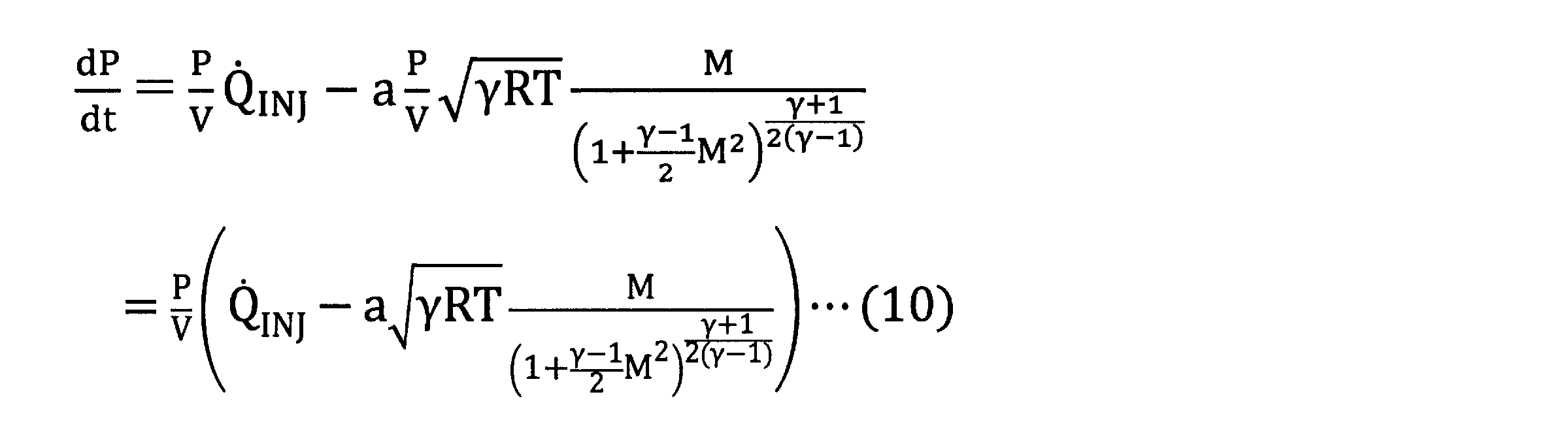
したがって、式(10)の右辺が正になるのは、例えば、噴射孔63の総面積が0.1mm2程度であれば、ポンプ41の吐出量は約78kg/h以上にする必要がある。一方、現存のポンプ41の吐出量は約1/4であるため、QINJはもっと少ないことになり、さらに一部はバイパス通路73にも流れるので、式(10)の右辺は系内圧力が1.9×105Pa=1.9bar程度以上であると、負になる。このため、系内圧力Pは降下し続ける。このことを示すシミュレーション計算結果を図21のグラフに示す。図21の点線は、第2の還元剤供給通路72内の尿素水7が噴射ノズル60側に圧送された際の残存空間を、系内圧力Pが第4圧力値P4となってステップS54Aで噴射ノズル60の弁が開かれる時点での初期空間の大きさで規格化した割合である。また、図21の一点鎖線で示す値(約0.24)は、残存空間が噴射ノズル60内のみになった状態を示す。したがって、残存空間比が一点鎖線のレベルまで低下した際の系内圧力Pの初期値(第4圧力値P4)に対する比を把握できる。このため、図21の場合であれば、系内圧力Pの初期値に対する比率が約0.13程度まで低下する前に噴射ノズル60の弁を閉じれば、尿素水7が噴射ノズル60に到達することを防止できる。したがって、第5圧力値P5を、第5圧力値P5/第4圧力値P4が0.13以上になる値に設定することで、尿素水7が噴射ノズル60に到達するまえに噴射ノズル60の弁を閉じることができる。
なお、ポンプ41の吐出能力が大きい場合は、この行程時にポンプ吐出量を式(10)の右辺が負になる値に固定する制御を行うことで、同じことを実現できる。
噴射ノズル60の開弁後、ポンプ41の圧送により、第2の還元剤供給通路72内の空間が少なくなり、かつ、系内圧力Pが降下する。噴射ノズル60に尿素水7が浸入する直前の系内圧力Pは第2の還元剤供給通路72の長さ(ホース長さ)、内径、ポンプ41のムダ容積、噴射ノズル60の容積、系内温度によって変化するが、ある程度の余裕分を見込んだ閾値圧力として第5圧力値P5を設定することができる。したがって、系内圧力Pを測定し、第5圧力値P5と比較すれば、尿素水7が噴射ノズル60に浸入する前に噴射ノズル60の弁を閉じ、尿素水7の浸入を回避する制御を行うことができる。
このような第2実施形態によれば、圧力計43で測定した系内圧力Pに基づいて、噴射ノズル60の開閉タイミング等を制御できる。また、系内圧力Pと比較する閾値である第1圧力値P1~第5圧力値P5は、前述したようなシミュレーションによって求めることができる。したがって、予め実験等を行って噴射ノズル60の開閉タイミングを設定する場合に比べて、準備作業が容易になる。特に、第1の還元剤供給通路71や第2の還元剤供給通路72を構成するホースの長さが異なる場合でも、個別に実験する必要が無いため、準備作業が容易になる。
例えば、還元剤供給通路70において、複数箇所に尿素水7の有無を検出するセンサを設け、制御装置5は、前記センサによって検出される尿素水7の移動位置に応じて噴射ノズル60やポンプ41、切換弁42の制御を行ってもよい。
また、前記各実施形態では、尿素水吸い戻し処理S3、S3Aを実行してから制御を終了していたが、圧縮ガス放出処理S5、S5Aが完了した時点で制御を終了してもよい。
Claims (6)
- エンジンの排気管内に供給される還元剤を貯蔵するタンクと、
前記タンク内の前記還元剤を圧送する圧送手段と、
圧送される前記還元剤を供給する還元剤供給通路と、
前記還元剤供給通路により供給された前記還元剤を前記排気管内に噴射する噴射ノズルと、
前記還元剤供給通路内の前記還元剤を前記タンク側に吸い戻す吸い戻し手段と、
前記圧送手段、前記噴射ノズルおよび前記吸い戻し手段の動作を制御する制御装置とを備え、
前記制御装置は、前記エンジンの停止後に、還元剤吸い戻し処理と圧縮ガス放出処理とを実行し、
前記還元剤吸い戻し処理では、前記制御装置は、
前記噴射ノズルを閉弁した状態で前記吸い戻し手段を作動して、前記還元剤供給通路内の前記還元剤を前記タンク側に吸い戻し、
前記噴射ノズルを開弁した状態で前記吸い戻し手段を作動して、前記噴射ノズルおよび前記還元剤供給通路内に前記排気管内のガスを導入し、
前記圧縮ガス放出処理では、前記制御装置は、
前記噴射ノズルを閉弁した状態で前記圧送手段を作動して前記還元剤供給通路に前記還元剤を供給し、前記還元剤供給通路内に導入された前記ガスを圧縮し、
前記噴射ノズルを開弁して前記圧縮されたガスを、前記噴射ノズルを通して前記排気管内に放出し、
前記還元剤供給通路内の前記還元剤が前記噴射ノズルに到達する前に前記噴射ノズルを閉弁する
ことを特徴とする還元剤供給装置。 - 請求項1に記載の還元剤供給装置において、
前記還元剤吸い戻し処理では、前記制御装置は、
前記噴射ノズルを閉弁した状態で前記吸い戻し手段を作動して、前記還元剤供給通路内の前記還元剤を前記タンク側に吸い戻し、
前記吸い戻し手段の作動を開始してから予め設定された第1設定時間経過時に、前記噴射ノズルを開弁し、前記噴射ノズルおよび前記還元剤供給通路内に前記排気管内のガスを導入し、
前記吸い戻し手段の作動を開始してから予め設定された第2設定時間経過時に、前記吸い戻し手段を停止し、
前記吸い戻し手段の作動を開始してから予め設定された第3設定時間経過時に、前記噴射ノズルを閉弁し、
前記圧縮ガス放出処理では、前記制御装置は、
前記噴射ノズルを閉弁した状態で前記圧送手段を作動して前記還元剤供給通路に前記還元剤を供給し、前記還元剤供給通路内に導入された前記ガスを圧縮し、
前記圧送手段を作動してから予め設定された第4設定時間経過時に前記噴射ノズルを開弁して前記圧縮されたガスを、前記噴射ノズルを通して前記排気管内に放出し、
前記圧送手段を作動してから予め設定された第5設定時間経過時に前記噴射ノズルを閉弁する
ことを特徴とする還元剤供給装置。 - 請求項1に記載の還元剤供給装置において、
前記還元剤供給通路内の圧力を測定する圧力計を備え、
前記還元剤吸い戻し処理では、前記制御装置は、
前記噴射ノズルを閉弁した状態で前記吸い戻し手段を作動して、前記還元剤供給通路内の前記還元剤を前記タンク側に吸い戻し、
前記吸い戻し手段の作動を開始してから前記圧力計の測定値が予め設定された第1圧力値になると、前記噴射ノズルを開弁し、前記噴射ノズルおよび前記還元剤供給通路内に前記排気管内のガスを導入し、
前記圧力計の測定値が前記第1圧力値よりも高い予め設定された第2圧力値になると、前記吸い戻し手段を停止し、
前記圧力計の測定値が前記第2圧力値よりも高い予め設定された第3圧力値になると、前記噴射ノズルを閉弁し、
前記圧縮ガス放出処理では、前記制御装置は、
前記噴射ノズルを閉弁した状態で前記圧送手段を作動して前記還元剤供給通路に前記還元剤を供給し、前記還元剤供給通路内に導入された前記ガスを圧縮し、
前記圧力計の測定値が前記第3圧力値よりも高い予め設定された第4圧力値になると、前記噴射ノズルを開弁して前記圧縮されたガスを、前記噴射ノズルを通して前記排気管内に放出し、
前記圧力計の測定値が前記前記第3圧力値よりも高くかつ前記第4圧力値よりも低い予め設定された第5圧力値になると、前記噴射ノズルを閉弁する
ことを特徴とする還元剤供給装置。 - 請求項3に記載の還元剤供給装置において、
前記第1圧力値と、前記第2圧力値と、前記第3圧力値と、前記第4圧力値と、前記第5圧力値とは、前記還元剤供給通路の内径および長さと、前記圧送手段および吸い戻し手段の容積と、前記噴射ノズルの容積とに基づいて算出された値である
ことを特徴とする還元剤供給装置。 - 請求項1から請求項4のいずれか一項に記載の還元剤供給装置において、
前記制御装置は、前記エンジンの停止後に、
前記還元剤吸い戻し処理および前記圧縮ガス放出処理を複数回繰り返した後、前記還元剤吸い戻し処理を実行する
ことを特徴とする還元剤供給装置。 - エンジンの排気管内に供給される還元剤を貯蔵するタンクと、
前記タンク内の前記還元剤を圧送する圧送手段と、
圧送される前記還元剤を供給する還元剤供給通路と、
前記還元剤供給通路により供給された前記還元剤を前記排気管内に噴射する噴射ノズルと、
前記還元剤供給通路内の前記還元剤を前記タンク側に吸い戻す吸い戻し手段と、を備えた還元剤供給装置の制御方法であって、
前記エンジンの停止後に、
前記噴射ノズルを閉弁した状態で前記吸い戻し手段を作動して、前記還元剤供給通路内の前記還元剤を前記タンク側に吸い戻し、
前記噴射ノズルを開弁した状態で前記吸い戻し手段を作動して、前記噴射ノズルおよび前記還元剤供給通路内に前記排気管内のガスを導入し、
前記噴射ノズルを閉弁した状態で前記圧送手段を作動して前記還元剤供給通路に前記還元剤を供給し、前記還元剤供給通路内に導入された前記ガスを圧縮し、
前記噴射ノズルを開弁して前記圧縮されたガスを、前記噴射ノズルを通して前記排気管内に放出し、
前記還元剤供給通路内の前記還元剤が前記噴射ノズルに到達する前に前記噴射ノズルを閉弁する
ことを特徴とする還元剤供給装置の制御方法。
Priority Applications (3)
| Application Number | Priority Date | Filing Date | Title |
|---|---|---|---|
| US15/526,562 US10309282B2 (en) | 2014-12-11 | 2014-12-11 | Reducing agent supply device and method for controlling reducing agent supply device |
| PCT/JP2014/082821 WO2016092665A1 (ja) | 2014-12-11 | 2014-12-11 | 還元剤供給装置および還元剤供給装置の制御方法 |
| JP2016563349A JP6564393B2 (ja) | 2014-12-11 | 2014-12-11 | 還元剤供給装置および還元剤供給装置の制御方法 |
Applications Claiming Priority (1)
| Application Number | Priority Date | Filing Date | Title |
|---|---|---|---|
| PCT/JP2014/082821 WO2016092665A1 (ja) | 2014-12-11 | 2014-12-11 | 還元剤供給装置および還元剤供給装置の制御方法 |
Publications (1)
| Publication Number | Publication Date |
|---|---|
| WO2016092665A1 true WO2016092665A1 (ja) | 2016-06-16 |
Family
ID=56106913
Family Applications (1)
| Application Number | Title | Priority Date | Filing Date |
|---|---|---|---|
| PCT/JP2014/082821 Ceased WO2016092665A1 (ja) | 2014-12-11 | 2014-12-11 | 還元剤供給装置および還元剤供給装置の制御方法 |
Country Status (3)
| Country | Link |
|---|---|
| US (1) | US10309282B2 (ja) |
| JP (1) | JP6564393B2 (ja) |
| WO (1) | WO2016092665A1 (ja) |
Cited By (5)
| Publication number | Priority date | Publication date | Assignee | Title |
|---|---|---|---|---|
| JP2018044526A (ja) * | 2016-09-16 | 2018-03-22 | 株式会社豊田自動織機 | 排気処理装置 |
| JP2020165429A (ja) * | 2019-03-28 | 2020-10-08 | マレリ・ヨーロッパ・エッセ・ピ・ア | 内燃エンジン内に水を噴射するための噴射方法およびシステム |
| CN113262376A (zh) * | 2021-04-27 | 2021-08-17 | 中国人民解放军西部战区总医院 | 一种肾移植专用输尿管支架 |
| US12078262B2 (en) | 2022-01-12 | 2024-09-03 | Fumoto Giken Co., Ltd. | Operation valve |
| DE112023001837T5 (de) | 2022-09-05 | 2025-01-23 | Komatsu Ltd. | Reduktionsmittel-Zufuhrvorrichtung, Verfahren zur Steuerung der Reduktionsmittel-Zufuhrvorrichtung und Steuervorrichtung |
Families Citing this family (8)
| Publication number | Priority date | Publication date | Assignee | Title |
|---|---|---|---|---|
| DE102018210622A1 (de) * | 2018-06-28 | 2020-01-02 | Dr Pley Engineering & Consulting (Bucharest) Srl | Reaktor zur thermohydrolyse von harnstoff |
| US11040308B2 (en) * | 2018-07-05 | 2021-06-22 | Cummins Emission Solutions Inc. | Systems and methods for purging reductant from a reductant injector |
| CN117267006A (zh) * | 2019-03-14 | 2023-12-22 | 康明斯有限公司 | 寒冷环境温度条件下使用气缸切断方法的柴油机排气流体剂量器保护 |
| CN111828148B (zh) * | 2019-04-15 | 2021-10-26 | 康明斯排放处理公司 | 用于检测未完成清除事件的系统和方法 |
| JP7383572B2 (ja) * | 2020-06-16 | 2023-11-20 | ボッシュ株式会社 | 還元剤供給装置 |
| CN112594039B (zh) * | 2021-01-14 | 2021-11-30 | 河南柴油机重工有限责任公司 | 一种便于清洗、可旋转且防结晶的scr喷嘴 |
| DE102022213813A1 (de) * | 2022-12-16 | 2024-06-27 | Vitesco Technologies GmbH | Verfahren zur Spülung einer Druckleitung einer Fördervorrichtung |
| CN119778110B (zh) * | 2025-01-13 | 2026-04-24 | 江苏上交碳中和科技有限公司 | 一种氨-柴油燃料发动机防止氨燃料液化装置及控制方法、设备和介质 |
Citations (4)
| Publication number | Priority date | Publication date | Assignee | Title |
|---|---|---|---|---|
| JP2009215891A (ja) * | 2008-03-07 | 2009-09-24 | Bosch Corp | 還元剤供給装置の制御装置及び還元剤の回収方法並びに排気浄化装置 |
| WO2014038084A1 (ja) * | 2012-09-10 | 2014-03-13 | トヨタ自動車 株式会社 | 添加剤供給システムの制御装置 |
| WO2014061377A1 (ja) * | 2012-10-18 | 2014-04-24 | ボッシュ株式会社 | 還元剤回収制御方法及び還元剤供給装置並びに電子制御装置 |
| JP2014218973A (ja) * | 2013-05-10 | 2014-11-20 | 株式会社日本自動車部品総合研究所 | 内燃機関の排気浄化装置 |
Family Cites Families (3)
| Publication number | Priority date | Publication date | Assignee | Title |
|---|---|---|---|---|
| KR100974599B1 (ko) * | 2008-08-07 | 2010-08-06 | 현대자동차주식회사 | 차량의 요소 분사량 제어장치 및 방법 |
| JP5653208B2 (ja) | 2010-12-27 | 2015-01-14 | ボッシュ株式会社 | 還元剤供給装置およびその制御方法 |
| US9397579B2 (en) * | 2011-07-15 | 2016-07-19 | O2Micro Inc | Full-bridge switching DC/DC converters and controllers thereof |
-
2014
- 2014-12-11 US US15/526,562 patent/US10309282B2/en active Active
- 2014-12-11 JP JP2016563349A patent/JP6564393B2/ja active Active
- 2014-12-11 WO PCT/JP2014/082821 patent/WO2016092665A1/ja not_active Ceased
Patent Citations (4)
| Publication number | Priority date | Publication date | Assignee | Title |
|---|---|---|---|---|
| JP2009215891A (ja) * | 2008-03-07 | 2009-09-24 | Bosch Corp | 還元剤供給装置の制御装置及び還元剤の回収方法並びに排気浄化装置 |
| WO2014038084A1 (ja) * | 2012-09-10 | 2014-03-13 | トヨタ自動車 株式会社 | 添加剤供給システムの制御装置 |
| WO2014061377A1 (ja) * | 2012-10-18 | 2014-04-24 | ボッシュ株式会社 | 還元剤回収制御方法及び還元剤供給装置並びに電子制御装置 |
| JP2014218973A (ja) * | 2013-05-10 | 2014-11-20 | 株式会社日本自動車部品総合研究所 | 内燃機関の排気浄化装置 |
Cited By (6)
| Publication number | Priority date | Publication date | Assignee | Title |
|---|---|---|---|---|
| JP2018044526A (ja) * | 2016-09-16 | 2018-03-22 | 株式会社豊田自動織機 | 排気処理装置 |
| JP2020165429A (ja) * | 2019-03-28 | 2020-10-08 | マレリ・ヨーロッパ・エッセ・ピ・ア | 内燃エンジン内に水を噴射するための噴射方法およびシステム |
| JP7477340B2 (ja) | 2019-03-28 | 2024-05-01 | マレリ・ヨーロッパ・エッセ・ピ・ア | 内燃エンジン内に水を噴射するための噴射方法およびシステム |
| CN113262376A (zh) * | 2021-04-27 | 2021-08-17 | 中国人民解放军西部战区总医院 | 一种肾移植专用输尿管支架 |
| US12078262B2 (en) | 2022-01-12 | 2024-09-03 | Fumoto Giken Co., Ltd. | Operation valve |
| DE112023001837T5 (de) | 2022-09-05 | 2025-01-23 | Komatsu Ltd. | Reduktionsmittel-Zufuhrvorrichtung, Verfahren zur Steuerung der Reduktionsmittel-Zufuhrvorrichtung und Steuervorrichtung |
Also Published As
| Publication number | Publication date |
|---|---|
| JP6564393B2 (ja) | 2019-08-21 |
| US10309282B2 (en) | 2019-06-04 |
| JPWO2016092665A1 (ja) | 2017-09-21 |
| US20170328253A1 (en) | 2017-11-16 |
Similar Documents
| Publication | Publication Date | Title |
|---|---|---|
| JP6564393B2 (ja) | 還元剤供給装置および還元剤供給装置の制御方法 | |
| JP5789925B2 (ja) | NOxセンサ診断装置及びSCRシステム | |
| CN101479450B (zh) | 发动机的排气净化装置 | |
| JP5547815B2 (ja) | 還元剤噴射弁の異常判定装置及び還元剤供給装置 | |
| EP2955352B1 (en) | Urea water supply system | |
| US8181448B2 (en) | System for controlling urea injection quantity of vehicle and method thereof | |
| JP4894827B2 (ja) | 還元剤供給システム | |
| JP5676631B2 (ja) | 還元剤供給装置及び還元剤供給装置の制御方法並びに排気浄化装置 | |
| WO2011145567A1 (ja) | Scr解凍制御システム | |
| EP3469197B1 (en) | Method for detecting a leak in a feed line of liquid system in a motor vehicle | |
| CN107427750A (zh) | 粗滤器 | |
| JP2010037979A (ja) | 排気浄化装置 | |
| KR20140035282A (ko) | 유체 분배 시스템 및 그 구성요소들 | |
| JP2014218973A (ja) | 内燃機関の排気浄化装置 | |
| KR101583891B1 (ko) | 디젤차량용 scr 시스템의 우레아 역류 방지 장치 | |
| JP5914004B2 (ja) | 還元剤供給装置 | |
| JP7013820B2 (ja) | 還元剤添加システム | |
| JP5948226B2 (ja) | 還元剤供給装置 | |
| JP2015148182A (ja) | 建設機械 | |
| US20210291085A1 (en) | Method for maintaining a filtration device of a system for extracting a liquid from a tank of a motor vehicle | |
| CN109983206B (zh) | 用于排气后处理系统的设备和控制用于发动机排气后处理系统的设备中的还原剂流动的方法 | |
| KR101800982B1 (ko) | 내연 기관 | |
| JP2024036012A (ja) | 還元剤供給装置、還元剤供給装置の制御方法および制御装置 | |
| WO2019181151A1 (ja) | 排気ガス浄化装置 | |
| JP2016098710A (ja) | 内燃機関の尿素水回収システム、内燃機関及び内燃機関の尿素水回収方法 |
Legal Events
| Date | Code | Title | Description |
|---|---|---|---|
| 121 | Ep: the epo has been informed by wipo that ep was designated in this application |
Ref document number: 14907816 Country of ref document: EP Kind code of ref document: A1 |
|
| ENP | Entry into the national phase |
Ref document number: 2016563349 Country of ref document: JP Kind code of ref document: A |
|
| WWE | Wipo information: entry into national phase |
Ref document number: 15526562 Country of ref document: US |
|
| NENP | Non-entry into the national phase |
Ref country code: DE |
|
| 122 | Ep: pct application non-entry in european phase |
Ref document number: 14907816 Country of ref document: EP Kind code of ref document: A1 |