WO2016084557A1 - Secondary battery with hydroxide-ion-conducting ceramic separator - Google Patents
Secondary battery with hydroxide-ion-conducting ceramic separator Download PDFInfo
- Publication number
- WO2016084557A1 WO2016084557A1 PCT/JP2015/080931 JP2015080931W WO2016084557A1 WO 2016084557 A1 WO2016084557 A1 WO 2016084557A1 JP 2015080931 W JP2015080931 W JP 2015080931W WO 2016084557 A1 WO2016084557 A1 WO 2016084557A1
- Authority
- WO
- WIPO (PCT)
- Prior art keywords
- secondary battery
- negative electrode
- porous substrate
- positive electrode
- separator
- Prior art date
Links
Images


Classifications
-
- H—ELECTRICITY
- H01—ELECTRIC ELEMENTS
- H01M—PROCESSES OR MEANS, e.g. BATTERIES, FOR THE DIRECT CONVERSION OF CHEMICAL ENERGY INTO ELECTRICAL ENERGY
- H01M10/00—Secondary cells; Manufacture thereof
- H01M10/24—Alkaline accumulators
- H01M10/30—Nickel accumulators
-
- H—ELECTRICITY
- H01—ELECTRIC ELEMENTS
- H01M—PROCESSES OR MEANS, e.g. BATTERIES, FOR THE DIRECT CONVERSION OF CHEMICAL ENERGY INTO ELECTRICAL ENERGY
- H01M10/00—Secondary cells; Manufacture thereof
- H01M10/24—Alkaline accumulators
- H01M10/26—Selection of materials as electrolytes
-
- H—ELECTRICITY
- H01—ELECTRIC ELEMENTS
- H01M—PROCESSES OR MEANS, e.g. BATTERIES, FOR THE DIRECT CONVERSION OF CHEMICAL ENERGY INTO ELECTRICAL ENERGY
- H01M10/00—Secondary cells; Manufacture thereof
- H01M10/34—Gastight accumulators
- H01M10/345—Gastight metal hydride accumulators
- H01M10/347—Gastight metal hydride accumulators with solid electrolyte
-
- H—ELECTRICITY
- H01—ELECTRIC ELEMENTS
- H01M—PROCESSES OR MEANS, e.g. BATTERIES, FOR THE DIRECT CONVERSION OF CHEMICAL ENERGY INTO ELECTRICAL ENERGY
- H01M12/00—Hybrid cells; Manufacture thereof
- H01M12/08—Hybrid cells; Manufacture thereof composed of a half-cell of a fuel-cell type and a half-cell of the secondary-cell type
-
- H—ELECTRICITY
- H01—ELECTRIC ELEMENTS
- H01M—PROCESSES OR MEANS, e.g. BATTERIES, FOR THE DIRECT CONVERSION OF CHEMICAL ENERGY INTO ELECTRICAL ENERGY
- H01M4/00—Electrodes
- H01M4/02—Electrodes composed of, or comprising, active material
- H01M4/24—Electrodes for alkaline accumulators
- H01M4/244—Zinc electrodes
-
- H—ELECTRICITY
- H01—ELECTRIC ELEMENTS
- H01M—PROCESSES OR MEANS, e.g. BATTERIES, FOR THE DIRECT CONVERSION OF CHEMICAL ENERGY INTO ELECTRICAL ENERGY
- H01M4/00—Electrodes
- H01M4/02—Electrodes composed of, or comprising, active material
- H01M4/24—Electrodes for alkaline accumulators
- H01M4/32—Nickel oxide or hydroxide electrodes
-
- H—ELECTRICITY
- H01—ELECTRIC ELEMENTS
- H01M—PROCESSES OR MEANS, e.g. BATTERIES, FOR THE DIRECT CONVERSION OF CHEMICAL ENERGY INTO ELECTRICAL ENERGY
- H01M4/00—Electrodes
- H01M4/02—Electrodes composed of, or comprising, active material
- H01M4/36—Selection of substances as active materials, active masses, active liquids
- H01M4/48—Selection of substances as active materials, active masses, active liquids of inorganic oxides or hydroxides
- H01M4/52—Selection of substances as active materials, active masses, active liquids of inorganic oxides or hydroxides of nickel, cobalt or iron
-
- H—ELECTRICITY
- H01—ELECTRIC ELEMENTS
- H01M—PROCESSES OR MEANS, e.g. BATTERIES, FOR THE DIRECT CONVERSION OF CHEMICAL ENERGY INTO ELECTRICAL ENERGY
- H01M50/00—Constructional details or processes of manufacture of the non-active parts of electrochemical cells other than fuel cells, e.g. hybrid cells
- H01M50/40—Separators; Membranes; Diaphragms; Spacing elements inside cells
- H01M50/409—Separators, membranes or diaphragms characterised by the material
- H01M50/431—Inorganic material
- H01M50/434—Ceramics
-
- H—ELECTRICITY
- H01—ELECTRIC ELEMENTS
- H01M—PROCESSES OR MEANS, e.g. BATTERIES, FOR THE DIRECT CONVERSION OF CHEMICAL ENERGY INTO ELECTRICAL ENERGY
- H01M50/00—Constructional details or processes of manufacture of the non-active parts of electrochemical cells other than fuel cells, e.g. hybrid cells
- H01M50/40—Separators; Membranes; Diaphragms; Spacing elements inside cells
- H01M50/409—Separators, membranes or diaphragms characterised by the material
- H01M50/449—Separators, membranes or diaphragms characterised by the material having a layered structure
-
- H—ELECTRICITY
- H01—ELECTRIC ELEMENTS
- H01M—PROCESSES OR MEANS, e.g. BATTERIES, FOR THE DIRECT CONVERSION OF CHEMICAL ENERGY INTO ELECTRICAL ENERGY
- H01M2300/00—Electrolytes
- H01M2300/0017—Non-aqueous electrolytes
- H01M2300/0065—Solid electrolytes
- H01M2300/0068—Solid electrolytes inorganic
- H01M2300/0071—Oxides
-
- H—ELECTRICITY
- H01—ELECTRIC ELEMENTS
- H01M—PROCESSES OR MEANS, e.g. BATTERIES, FOR THE DIRECT CONVERSION OF CHEMICAL ENERGY INTO ELECTRICAL ENERGY
- H01M2300/00—Electrolytes
- H01M2300/0088—Composites
- H01M2300/0094—Composites in the form of layered products, e.g. coatings
-
- Y—GENERAL TAGGING OF NEW TECHNOLOGICAL DEVELOPMENTS; GENERAL TAGGING OF CROSS-SECTIONAL TECHNOLOGIES SPANNING OVER SEVERAL SECTIONS OF THE IPC; TECHNICAL SUBJECTS COVERED BY FORMER USPC CROSS-REFERENCE ART COLLECTIONS [XRACs] AND DIGESTS
- Y02—TECHNOLOGIES OR APPLICATIONS FOR MITIGATION OR ADAPTATION AGAINST CLIMATE CHANGE
- Y02E—REDUCTION OF GREENHOUSE GAS [GHG] EMISSIONS, RELATED TO ENERGY GENERATION, TRANSMISSION OR DISTRIBUTION
- Y02E60/00—Enabling technologies; Technologies with a potential or indirect contribution to GHG emissions mitigation
- Y02E60/10—Energy storage using batteries
Definitions
- the present invention relates to a secondary battery using a hydroxide ion conductive ceramic separator.
- zinc secondary batteries such as nickel zinc secondary batteries and zinc-air secondary batteries have been developed and studied for a long time, they have not yet been put into practical use. This is because the zinc constituting the negative electrode produces dendritic crystals called dendrite during charging, and this dendrite breaks through the separator and causes a short circuit with the positive electrode. Therefore, a technique for preventing a short circuit due to zinc dendrite in a zinc secondary battery such as a nickel zinc secondary battery or a zinc-air secondary battery is strongly desired.
- Patent Document 1 International Publication No. 2013/118561
- a separator made of a hydroxide ion conductive inorganic solid electrolyte is used as a positive electrode in a nickel zinc secondary battery for the purpose of preventing a short circuit due to zinc dendrite.
- an inorganic solid electrolyte body having a general formula: M 2+ 1-x M 3+ x (OH) 2 A n ⁇ x / n ⁇ mH 2 O (wherein M 2+ is at least is at least one divalent cation, M 3+ is at least one or more trivalent cations, a n-is the n-valent anion, n represents an integer of 1 or more, x is 0 It has been proposed to use a layered double hydroxide (LDH) having a basic composition of .1 to 0.4. Further, in Patent Document 2 (International Publication No.
- a separator made of layered double hydroxide (LDH) having the same basic composition as described above is brought into close contact with one side of the air electrode. It has been proposed that both the short circuit between the positive and negative electrodes due to zinc dendrite during charging and the mixing of carbon dioxide into the electrolyte can be prevented.
- LDH layered double hydroxide
- Patent Document 3 International Publication No. 2013/1615166 describes a layered double hydroxide (LDH) having the same basic composition as described above.
- LDH layered double hydroxide
- a lithium-air secondary battery using a constructed inorganic solid electrolyte as an anion exchanger is disclosed, and this anion exchanger can prevent carbon dioxide from being mixed into the battery.
- the present applicant has succeeded in developing a ceramic separator (inorganic solid electrolyte separator) that has hydroxide ion conductivity but is highly densified to such an extent that it does not have water permeability and air permeability. Moreover, it has succeeded also in forming such a ceramic separator on a porous base material (for example, alumina porous base material).
- a separator or a separator with a porous substrate
- a secondary battery such as a zinc-nickel battery or a zinc-air secondary battery
- a short circuit due to zinc dendrite (especially in the case of a metal-air secondary battery) (Problem) carbon dioxide contamination can be prevented.
- the ceramic separator needs a certain strength.
- the hydroxide ion conductive ceramic separator is formed thick to increase the strength, there is a problem that the resistance of the hydroxide ion conductive ceramic separator increases. Therefore, it is desired to provide the ceramic separator with high strength that can withstand practical use while reducing the resistance by forming a thin hydroxide ion conductive ceramic separator.
- forming a ceramic separator on a porous substrate is a promising technique in that a thin ceramic separator can be formed while reducing the concern about strength.
- a porous substrate for example, an alumina porous substrate
- the porous base material into the secondary battery, another concern that the energy density of the battery decreases or the internal resistance of the battery increases may arise. That is, assuming a secondary battery having the same volume, the greater the thickness of the porous substrate, the smaller the amount of electrode active material that can be filled, so the energy density of the secondary battery becomes smaller. Further, the resistance due to the porous base material leads to an increase in the internal resistance of the secondary battery.
- the present inventors provide a porous substrate having a predetermined specification on at least one surface of the ceramic separator. The knowledge that the decrease in energy density and the increase in internal resistance due to the incorporation of the porous base material can be desirably suppressed while realizing the low resistance by reducing the thickness of the ceramic separator without causing the concern of the decrease in strength. Obtained.
- an object of the present invention is a secondary battery using a ceramic separator made of an inorganic solid electrolyte body having hydroxide ion conductivity, and there is a concern that a reduction in resistance due to the thinning of the ceramic separator causes a reduction in strength.
- An object of the present invention is to provide a secondary battery capable of desirably suppressing a decrease in energy density and an increase in internal resistance while realizing the above.
- a secondary battery using a hydroxide ion conductive ceramic separator wherein the secondary battery includes a positive electrode, a negative electrode, an alkaline electrolyte, the positive electrode, and the negative electrode.
- a battery is provided.
- the positive electrode contains nickel hydroxide and / or nickel oxyhydroxide
- the electrolyte is composed of a positive electrode electrolyte in which the positive electrode is immersed and a negative electrode electrolyte in which the negative electrode is immersed
- the container contains the positive electrode, the positive electrode electrolyte, the negative electrode, the negative electrode electrolyte, the ceramic separator, and the porous substrate;
- the ceramic separator is provided in the container so as to partition a positive electrode chamber containing the positive electrode and the positive electrode electrolyte, and a negative electrode chamber containing the negative electrode and the negative electrode electrolyte, whereby the battery is It can be a nickel zinc secondary battery.
- the positive electrode is an air electrode
- the negative electrode is immersed in the electrolyte
- the container has an opening and contains the negative electrode and the electrolyte;
- the ceramic separator closes the opening so as to be in contact with the electrolytic solution to form the container and a negative electrode side sealed space, thereby isolating the air electrode and the electrolytic solution so as to conduct hydroxide ions,
- the battery can be a zinc-air secondary battery.
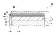
- FIG. 3B is a perspective view of the zinc-air secondary battery shown in FIG. 3A. It is a schematic cross section showing one mode of a separator with a porous substrate. It is a schematic cross section which shows the other one aspect
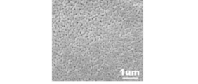
- FIG. 2 is a SEM image of the surface of an alumina porous substrate produced in Example 1.
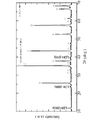
- FIG. 3 is an XRD profile obtained for the crystal phase of the sample in Example 1.
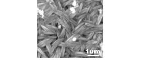
- 2 is an SEM image showing a surface microstructure of a film sample observed in Example 1.
- 2 is an SEM image of a polished cross-sectional microstructure of a composite material sample observed in Example 1.
- FIG. 2 is an exploded perspective view of a denseness discrimination measurement system used in Example 1.
- FIG. 2 is a schematic cross-sectional view of a denseness discrimination measurement system used in Example 1.
- FIG. FIG. 3 is an exploded perspective view of a measurement sealed container used in the denseness determination test II of Example 1.
- FIG. 6 is a graph showing the relationship between the thickness (cm) of a porous substrate and energy density (%) obtained in Example 3.
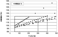
- 6 is a graph showing the relationship between the porosity (%) and internal resistance (%) of a porous substrate obtained in Example 3. Relationship between the value of T ⁇ D / 100 and the internal resistance obtained in Example 3 (where T is the thickness ( ⁇ m) of the porous substrate and the relative density (%) of the porous substrate) It is a graph showing.
- the secondary battery of the present invention uses a hydroxide ion conductive ceramic separator.
- the secondary battery of the present invention includes a nickel zinc secondary battery, a silver zinc oxide secondary battery, a manganese zinc secondary battery, a zinc air secondary battery, various other alkaline zinc secondary batteries, and a lithium air secondary battery. And various secondary batteries to which a hydroxide ion conductive ceramic separator can be applied.
- a nickel zinc secondary battery and a zinc-air secondary battery are preferable, and a nickel zinc secondary battery is most preferable. Therefore, in the following general description, reference may be made to FIGS. 1A and 1B relating to a nickel zinc secondary battery and FIGS. 3A and 3B relating to a zinc-air secondary battery.
- the secondary battery of the present invention may be referred to as a nickel zinc secondary battery.
- the present invention should not be limited to zinc-air secondary batteries, and conceptually includes the various secondary batteries described above that can employ hydroxide ion conductive ceramic separators.
- the secondary battery according to one embodiment of the present invention includes a positive electrode, a negative electrode, an alkaline electrolyte, a ceramic separator, a porous substrate, and a container.
- the ceramic separator is made of an inorganic solid electrolyte body that separates the positive electrode and the negative electrode and has hydroxide ion conductivity, and is in the form of a film or a layer that is so dense that the inorganic solid electrolyte body does not have water permeability.
- a porous substrate (preferably a ceramic porous substrate) is provided on at least one surface of the ceramic separator. The thickness of the porous substrate is 100 to 1800 ⁇ m.
- the positive electrode may be appropriately selected according to the type of secondary battery, and may be an air electrode.
- the negative electrode may be appropriately selected according to the type of secondary battery.
- the container contains at least a negative electrode and an alkaline electrolyte.
- the container 22 can also contain the positive electrode 12 and the positive electrode electrolyte 14, but like the zinc-air secondary battery 30 shown in FIG.
- the air electrode 32 (positive electrode) does not need to be completely accommodated in the container 46, and is simply attached so as to close the opening 46a of the container 46 (for example, in the form of a lid). May be.
- the positive electrode and the alkaline electrolyte need not necessarily be separated, and may be configured as a positive electrode mixture in which the positive electrode and the alkaline electrolyte are mixed. No liquid is required.
- the negative electrode and the alkaline electrolyte need not necessarily be separated, and may be configured as a negative electrode mixture in which the negative electrode and the alkaline electrolyte are mixed.
- a positive electrode current collector may be provided in contact with the positive electrode.
- a negative electrode current collector may be provided in contact with the negative electrode.
- Ceramic separator (hereinafter also simply referred to as “separator”) is provided so as to separate the positive electrode and the negative electrode.
- the separator 20 accommodates the positive electrode chamber 24 containing the positive electrode 12 and the positive electrode electrolyte solution 14, and the negative electrode 16 and the negative electrode electrolyte solution 18 in the container 22.
- the separator 40 may block the opening 46a of the container 46 so as to be in contact with the electrolytic solution 36, as in the zinc-air secondary battery 30 shown in FIG. 3A.
- the container 46 and the negative electrode side sealed space may be formed.
- the separator preferably has hydroxide ion conductivity but does not have water permeability (preferably water permeability and air permeability).
- the separator does not have water permeability and air permeability means that the separator has a high degree of denseness that does not allow water and gas to pass through. It means not a porous material.
- a zinc secondary battery it has a very effective configuration for physically preventing penetration of the separator by zinc dendrite generated during charging and preventing a short circuit between the positive and negative electrodes.
- a metal-air secondary battery a configuration that is extremely effective in preventing the infiltration of carbon dioxide in the air and preventing the precipitation of alkali carbonate (caused by carbon dioxide) in the electrolyte. It has become.
- the ceramic separator has hydroxide ion conductivity, the efficiency of hydroxide ions required between the positive electrode side (for example, alkaline electrolyte or air electrode) and the negative electrode side (for example, alkaline electrolyte). Charge and discharge reactions at the positive electrode and the negative electrode can be realized.
- the positive electrode side for example, alkaline electrolyte or air electrode
- the negative electrode side for example, alkaline electrolyte
- the ceramic separator is made of an inorganic solid electrolyte having hydroxide ion conductivity.
- a hydroxide ion conductive inorganic solid electrolyte as a separator, the electrolyte solution between the positive and negative electrodes is isolated and hydroxide ion conductivity is ensured.
- the inorganic solid electrolyte body is so dense that it does not have water permeability (preferably water permeability and air permeability).
- the inorganic solid electrolyte body preferably has a relative density of 90% or more, more preferably 92% or more, and even more preferably 95% or more, calculated by the Archimedes method, but prevents penetration of zinc dendrite.
- Such a dense and hard inorganic solid electrolyte body can be produced through a hydrothermal treatment. Therefore, a simple green compact that has not been subjected to hydrothermal treatment is not preferable as the inorganic solid electrolyte body of the present invention because it is not dense and is brittle in solution.
- any manufacturing method can be used as long as a dense and hard inorganic solid electrolyte body can be obtained, even if it has not undergone hydrothermal treatment.
- the ceramic separator or the inorganic solid electrolyte body may be a composite of a particle group including an inorganic solid electrolyte having hydroxide ion conductivity and an auxiliary component that assists densification and hardening of the particle group.
- the separator is a composite of an open-pore porous material as a base material and an inorganic solid electrolyte (for example, layered double hydroxide) deposited and grown in the pores so as to fill the pores of the porous material. It may be a body.
- the substance constituting the porous body include ceramics such as alumina and zirconia, and insulating substances such as a porous sheet made of a foamed resin or a fibrous substance.
- the inorganic solid electrolyte has a general formula: M 2+ 1-x M 3+ x (OH) 2 A n ⁇ x / n ⁇ mH 2 O (wherein M 2+ is a divalent cation and M 3+ is 3 the valence of the cation, a n-is the n-valent anion, n is an integer of 1 or more, the layered double hydroxide having a basic composition of x is 0.1 to 0.4)
- it comprises (LDH), more preferably such LDH.
- M 2+ may be any divalent cation, and preferred examples include Mg 2+ , Ca 2+ and Zn 2+ , and more preferably Mg 2+ .
- M 3+ may be any trivalent cation, but preferred examples include Al 3+ or Cr 3+ , and more preferred is Al 3+ .
- a n- can be any anion, but preferred examples include OH - and CO 3 2- . Therefore, in the general formula, M 2+ comprises Mg 2+, M 3+ comprises Al 3+, A n-is OH - and / or CO preferably contains 3 2-.
- n is an integer of 1 or more, preferably 1 or 2.
- x is 0.1 to 0.4, preferably 0.2 to 0.35.
- m is an arbitrary real number.
- the inorganic solid electrolyte body is preferably one that has been densified by hydrothermal treatment (that is, a hydrothermal compound).
- Hydrothermal treatment is extremely effective for the densification of layered double hydroxides, especially Mg—Al type layered double hydroxides.
- Densification by hydrothermal treatment is performed, for example, as described in Patent Document 1 (International Publication No. 2013/118561), in which pure water and a plate-shaped green compact are placed in a pressure vessel, and 120 to 250 ° C., preferably The reaction can be carried out at a temperature of 180 to 250 ° C., 2 to 24 hours, preferably 3 to 10 hours.
- a more preferable production method using hydrothermal treatment will be described later.
- the inorganic solid electrolyte body may be in the form of a film or layer that is so dense that it does not have water permeability, and the film or layer of the inorganic solid electrolyte body is on or in the porous substrate. It is preferably formed.
- the film or layer is thinner than the plate, there is an advantage that the resistance of the separator can be significantly reduced while ensuring the necessary minimum rigidity for preventing the penetration of zinc dendrite.
- the thickness is preferably 100 ⁇ m or less, more preferably 75 ⁇ m or less, still more preferably 50 ⁇ m or less, particularly preferably 25 ⁇ m or less, and most preferably 5 ⁇ m or less.
- the resistance of the separator can be reduced by being thin.
- the lower limit of the thickness is not particularly limited because it varies depending on the application, but in order to ensure a certain degree of rigidity desired as a separator film or layer, the thickness is preferably 1 ⁇ m or more, more preferably 2 ⁇ m or more. is there.
- a porous substrate is provided on at least one surface of the ceramic separator. It goes without saying that the porous substrate 28 has water permeability, and therefore, the alkaline electrolyte can reach the separator. However, the presence of the porous substrate allows hydroxide ions to be more stably formed on the separator. It can also be held. In addition, since the strength can be imparted by the porous base material, the resistance can be reduced by thinning the separator. Also, a dense film or a dense layer of an inorganic solid electrolyte (preferably LDH) can be formed on or in the porous substrate.
- an inorganic solid electrolyte preferably LDH
- a method of preparing a porous substrate and depositing an inorganic solid electrolyte on the porous substrate can be considered (this method will be described later).
- a porous base material on both surfaces of a separator it can be considered that densification is performed by sandwiching a raw material powder of an inorganic solid electrolyte between two porous base materials.
- the porous substrate 28 is provided over the entire surface of one side of the separator 20, but may be provided only on a part of one side of the separator 20 (for example, a region involved in the charge / discharge reaction).
- the porous substrate is provided over the entire surface of one side of the separator derived from the manufacturing method. Is typical.
- a porous base material is retrofitted only on a part of one side of the separator (for example, a region involved in the charge / discharge reaction).
- a porous substrate may be retrofitted over the entire surface of one side.
- the thickness of the porous substrate is 100 to 1800 ⁇ m, preferably 150 to 1500 ⁇ m, more preferably 200 to 900 ⁇ m, still more preferably 250 to 700 ⁇ m, and particularly preferably 250 to 500 ⁇ m.
- the hydroxide ion conductive ceramic separator is formed thick in order to increase the strength, there is a problem that the resistance of the hydroxide ion conductive ceramic separator is increased. Therefore, it is desired to provide the ceramic separator with high strength that can withstand practical use while reducing the resistance by forming a thin hydroxide ion conductive ceramic separator.
- forming a ceramic separator on a porous substrate is a promising technique in that a thin ceramic separator can be formed while reducing the concern about strength.
- a porous substrate for example, an alumina porous substrate
- the porous base material into the secondary battery, another concern that the energy density of the battery decreases or the internal resistance of the battery increases may arise. That is, assuming a secondary battery having the same volume, the greater the thickness of the porous substrate, the smaller the amount of electrode active material that can be filled, so the energy density of the secondary battery becomes smaller. Further, the resistance due to the porous base material leads to an increase in the internal resistance of the secondary battery.
- the thickness of the porous base material within the above range, the energy associated with the incorporation of the porous base material can be achieved while reducing the resistance by thinning the ceramic separator without causing the fear of the strength reduction.
- a decrease in density and an increase in internal resistance can be desirably suppressed.
- it since it will be hard to collapse if it is a porous base material of the thickness within the said range, it is easy to manufacture and handle it.
- the porous substrate preferably has a porosity of 10 to 90%, preferably 15 to 80%, more preferably 20 to 70%, still more preferably 30 to 70%, and particularly preferably 30 to 60%. . It is more desirable that the porosity within these ranges is realized in combination with the above-described thickness. In the porous substrate within these ranges, the desired water permeability can be secured, so that the electrolyte can be desirably reached and contacted with the ceramic separator, and as a result, the function as a battery can be secured. it can. Moreover, if it is the surface of the porous base material of the porosity within the said range, a dense LDH containing separator layer can be formed so that it may not have water permeability. The larger the porosity of the porous substrate, the smaller the internal resistance. However, a porous substrate having a porosity within the above range is less likely to collapse, and is easy to manufacture and handle.
- the porosity of the porous substrate is preferably measured based on the surface of the porous substrate. This is because it is easy to measure the porosity using the image processing described below, and it can be said that the porosity of the surface of the porous substrate generally represents the porosity inside the porous substrate. It is. That is, if the surface of the porous substrate is dense, the inside of the porous substrate can be said to be dense as well.
- the porosity of the surface of the porous substrate can be measured as follows by a technique using image processing.
- T thickness of the porous substrate
- P porosity of the porous substrate
- D relative density of the porous substrate
- T ⁇ D / 100 is preferably 50 to 400, more preferably 50 to 350, still more preferably 50 to 300, particularly preferably 100 to 300, and most preferably 100 to 250.
- the battery performance improves as the thickness is smaller and the porosity is higher. This is because the smaller the thickness, the lower the internal resistance, and the higher the porosity, the easier it is for the electrolyte to reach and contact the ceramic separator, resulting in a lower internal resistance.
- the porous substrate preferably has an average pore diameter of 0.001 to 1.5 ⁇ m, more preferably 0.001 to 1.25 ⁇ m, still more preferably 0.001 to 1.0 ⁇ m, and particularly preferably 0.001. 0.75 ⁇ m, most preferably 0.001 to 0.5 ⁇ m.
- the average pore diameter can be measured by measuring the longest distance of the pores based on an electron microscope (SEM) image of the surface of the porous substrate.
- the magnification of the electron microscope (SEM) image used for this measurement is 20000 times, and all obtained pore diameters are arranged in order of size, and the top 15 points and the bottom 15 points from the average value, with 30 points per field of view in total.
- the average pore diameter can be obtained by calculating an average value for two visual fields.
- a length measurement function of SEM software, image analysis software (for example, Photoshop, manufactured by Adobe) or the like can be used.
- the porous substrate is preferably composed of at least one selected from the group consisting of ceramic materials, metal materials, and polymer materials. More preferably, the porous substrate is made of a ceramic material.
- the ceramic material include alumina, zirconia, titania, magnesia, spinel, calcia, cordierite, zeolite, mullite, ferrite, zinc oxide, silicon carbide, and any combination thereof, and more preferable. Is alumina, zirconia, titania, and any combination thereof, particularly preferably alumina and zirconia, most preferably alumina. When these porous ceramics are used, it is easy to form an LDH-containing separator layer having excellent denseness.
- Preferable examples of the metal material include aluminum and zinc.
- Preferable examples of the polymer material include polystyrene, polyether sulfone, polypropylene, epoxy resin, polyphenylene sulfide, hydrofluorinated fluororesin (tetrafluorinated resin: PTFE, etc.), and any combination thereof. It is more preferable to appropriately select a material excellent in alkali resistance as the resistance to the battery electrolyte from the various preferable materials described above.
- the alkaline electrolyte may be any alkaline electrolyte that can be used in a secondary battery, but is preferably an aqueous solution of an alkali metal hydroxide. As shown in FIG. 1A, when the positive electrode electrolyte 14 and the negative electrode electrolyte 18 are present, an aqueous solution containing an alkali metal hydroxide is preferably used as the positive electrode electrolyte 14 and the negative electrode electrolyte 18.
- the alkali metal hydroxide include potassium hydroxide, sodium hydroxide, lithium hydroxide, ammonium hydroxide and the like, and potassium hydroxide is more preferable.
- a zinc compound such as zinc oxide or zinc hydroxide may be added to the electrolytic solution in order to suppress self-dissolution of the zinc alloy.
- the alkaline electrolyte may be mixed with the positive electrode and / or the negative electrode to be present in the form of a positive electrode mixture and / or a negative electrode mixture.
- the electrolytic solution may be gelled in order to prevent leakage of the electrolytic solution.
- the gelling agent it is desirable to use a polymer that swells by absorbing the solvent of the electrolytic solution, and polymers such as polyethylene oxide, polyvinyl alcohol, and polyacrylamide, and starch are used.
- the container contains at least the negative electrode and the alkaline electrolyte, and is preferably made of resin.
- the container 22 can also contain the positive electrode 12 and the positive electrode electrolyte solution 14 like the nickel zinc secondary battery 10 shown in FIGS. 1A and 1B, but like the zinc-air secondary battery 30 shown in FIG. 3A.
- the positive electrode is configured as the air electrode 32
- the air electrode 32 does not need to be completely accommodated in the container 46, and simply closes the opening 46 a of the container 46 (for example, like a lid). May be attached).
- the container preferably has a structure having liquid tightness and air tightness.
- the resin constituting the container is preferably a resin having resistance to an alkali metal hydroxide such as potassium hydroxide, more preferably a polyolefin resin, an ABS resin, or a modified polyphenylene ether, and further preferably an ABS resin or a modified polyphenylene. Ether.
- a ceramic separator and / or a ceramic porous member is fixed to the container using the adhesive described above.
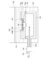
- FIG. 1A schematically shows an example of a nickel zinc secondary battery according to this embodiment.
- the nickel-zinc secondary battery shown in FIG. 1A shows an initial state before charging, and corresponds to an end-of-discharge state.
- the nickel-zinc secondary battery of this embodiment may be configured in a fully charged state.
- the nickel zinc secondary battery 10 according to this embodiment includes a positive electrode 12, a positive electrode electrolyte solution 14, a negative electrode 16, a negative electrode electrolyte solution 18, and a ceramic separator 20 in a container 22.
- the positive electrode 12 includes nickel hydroxide and / or nickel oxyhydroxide.
- the positive electrode electrolyte 14 is an alkaline electrolyte containing an alkali metal hydroxide, and the positive electrode 12 is immersed therein.
- the negative electrode 16 includes zinc and / or zinc oxide.
- the negative electrode electrolyte 18 is an alkaline electrolyte containing an alkali metal hydroxide, and the negative electrode 16 is immersed therein.
- the container 22 accommodates the positive electrode 12, the positive electrode electrolyte 14, the negative electrode 16, the negative electrode electrolyte 18, the ceramic separator 20, and the porous substrate 28.
- the positive electrode 12 and the positive electrode electrolyte solution 14 are not necessarily separated from each other, and may be configured as a positive electrode mixture in which the positive electrode 12 and the positive electrode electrolyte solution 14 are mixed.
- the negative electrode 16 and the negative electrode electrolyte 18 are not necessarily separated from each other, and may be configured as a negative electrode mixture in which the negative electrode 16 and the negative electrode electrolyte 18 are mixed. If desired, a positive electrode current collector 13 is provided in contact with the positive electrode 12. Further, if desired, a negative electrode current collector 17 is provided in contact with the negative electrode 16.
- the separator 20 is provided in the container 22 so as to partition a positive electrode chamber 24 that accommodates the positive electrode 12 and the positive electrode electrolyte solution 14 and a negative electrode chamber 26 that accommodates the negative electrode 16 and the negative electrode electrolyte solution 18.
- a porous substrate 28 is provided on at least one surface of the separator 20 (on the negative electrode 16 side in the illustrated example).
- the separator 20 has hydroxide ion conductivity but does not have water permeability.
- the fact that the separator 20 does not have water permeability means that the separator 20 has a high degree of denseness that does not allow water to pass through, and is not a porous film or other porous material having water permeability. Means.
- the porous substrate 28 may be attached to the separator 20 as shown in FIG. 1A.
- the separator 20 has hydroxide ion conductivity, it is possible to efficiently move the required hydroxide ions between the positive electrode electrolyte 14 and the negative electrode electrolyte 18, and the positive electrode chamber 24 and the negative electrode.
- the charge / discharge reaction in the chamber 26 can be realized.
- the reaction at the time of charging in the positive electrode chamber 24 and the negative electrode chamber 26 is as shown below, and the discharge reaction is reversed.
- the negative electrode reaction is composed of the following two reactions.
- -ZnO dissolution reaction ZnO + H 2 O + 2OH ⁇ ⁇ Zn (OH) 4 2 ⁇ - precipitation reaction of Zn: Zn (OH) 4 2- + 2e - ⁇ Zn + 4OH -
- the nickel-zinc secondary battery 10 has a positive electrode side surplus space 25 having a volume that allows an increase or decrease in the amount of water accompanying the positive electrode reaction during charge / discharge in the positive electrode chamber 24, and the negative electrode reaction during charge / discharge in the negative electrode chamber 26. It is preferable to have the negative electrode-side surplus space 27 having a volume that allows a decrease in the amount of water accompanying the above. This effectively prevents problems associated with the increase or decrease in the amount of water in the positive electrode chamber 24 and the negative electrode chamber 26 (for example, liquid leakage, deformation of the container due to changes in the container internal pressure, etc.), and the reliability of the nickel zinc secondary battery. Can be further improved.
- the positive electrode chamber 24 has a positive electrode-side surplus space 25 having a volume that allows an increase or decrease in the amount of water associated with the positive electrode reaction during charging and discharging, thereby increasing the positive electrolyte 14 during charging as shown in FIG. 1B. It can be made to function as a buffer that can cope with this. That is, as shown in FIG. 1B, the positive electrode side excess space 25 functions as a buffer even after full charge, so that the increased amount of the positive electrode electrolyte solution 14 is reliably held in the positive electrode chamber 24 without overflowing. Can do.
- the negative electrode chamber 26 has a negative electrode-side surplus space 27 having a volume that allows a decrease in the amount of water associated with the negative electrode reaction during charge / discharge, thereby functioning as a buffer that can cope with an increase in the negative electrode electrolyte 18 during discharge. Can be made.
- moisture content in the positive electrode chamber 24 and the negative electrode chamber 26 can be calculated based on the reaction formula mentioned above.
- the amount of H 2 O produced at the positive electrode 12 during charging corresponds to twice the amount of H 2 O consumed at the negative electrode 16. Therefore, the volume of the positive electrode side surplus space 25 may be larger than that of the negative electrode side surplus space 27.
- the volume of the positive-side surplus space 25 can be generated not only from the amount of water increase expected in the positive electrode chamber 24 but also from the positive electrode 12 during overcharge or a gas such as air existing in the positive electrode chamber 24 in advance. It is preferable that the volume has a slight or some margin so that oxygen gas can be accommodated at an appropriate internal pressure.
- the negative-side surplus space 27 has the same volume as that of the positive-side surplus space 25 as shown in FIG. 1A. It is desirable to provide a surplus space that exceeds the amount of water reduction. In any case, the negative electrode side surplus space 27 may be smaller than the positive electrode side surplus space 25 because the amount of water increases or decreases by about half of the amount in the positive electrode chamber 24.
- the positive electrode side surplus space 25 has a volume exceeding the amount of water expected to increase with the positive electrode reaction during charging, and the positive electrode side surplus space
- the space 25 is not filled with the positive electrode electrolyte 14 in advance and the negative electrode side surplus space 27 has a volume exceeding the amount of water expected to decrease with the negative electrode reaction during charging, and the negative electrode side surplus
- the space 27 is preferably filled in advance with an amount of the negative electrode electrolyte 18 that is expected to decrease.
- the positive-side surplus space 25 has a volume exceeding the amount of water expected to decrease with the positive electrode reaction during discharge
- the side surplus space 25 is pre-filled with an amount of the positive electrode electrolyte 14 that is expected to decrease, and the negative side surplus space 27 has a moisture amount that is expected to increase with the negative electrode reaction during discharge.
- the negative electrode side excess space 27 is not filled with the negative electrode electrolyte 18 in advance.
- the positive electrode side surplus space 25 is not filled with the positive electrode 12 and / or the negative electrode side surplus space 27 is not filled with the negative electrode 16, and the positive electrode side surplus space 25 and the negative electrode side surplus space 27 are filled with the positive electrode 12. More preferably, the negative electrode 16 and the negative electrode 16 are not filled. In these surplus spaces, electrolyte can be depleted due to a decrease in the amount of water during charging and discharging. That is, even if these surplus spaces are filled with the positive electrode 12 and the negative electrode 16, they cannot be sufficiently involved in the charge / discharge reaction, which is inefficient. Therefore, the positive electrode 12 and the negative electrode 16 can be more efficiently and stably involved in the battery reaction without waste by not filling the positive electrode 12 and the negative electrode 16 in the positive electrode side excess space 25 and the negative electrode side excess space 27, respectively.
- a second separator made of a water-absorbing resin such as a nonwoven fabric or a liquid-retaining resin is disposed between the positive electrode 12 and the separator 20 and / or between the negative electrode 16 and the separator 20, and the electrolytic solution Even in a case where the amount of the electrolyte decreases, the electrolytic solution may be held in the reaction part of the positive electrode and / or the negative electrode.
- the water absorbent resin or the liquid retaining resin include polyolefin resins.
- the positive electrode 12 includes nickel hydroxide and / or nickel oxyhydroxide.
- nickel hydroxide may be used as the positive electrode 12, and when configured in a fully charged state as shown in FIG. 1B. May use nickel oxyhydroxide as the positive electrode 12.
- Nickel hydroxide and nickel oxyhydroxide are positive electrode active materials generally used in nickel zinc secondary batteries and are typically in the form of particles.
- different elements other than nickel may be dissolved in the crystal lattice, thereby improving the charging efficiency at high temperatures. Examples of such different elements include zinc and cobalt.
- nickel hydroxide or the like may be mixed with a cobalt-based component, and examples of such a cobalt-based component include granular materials of metallic cobalt and cobalt oxide (for example, cobalt monoxide). .
- the surface of particles such as nickel hydroxide (which may contain different elements in solid solution) may be coated with a cobalt compound.
- cobalt compounds include cobalt monoxide, divalent ⁇ -type. Examples include cobalt hydroxide, divalent ⁇ -type cobalt hydroxide, compounds of higher-order cobalt exceeding 2 valences, and any combination thereof.
- the positive electrode 12 may further contain an additional element in addition to the nickel hydroxide compound and the different element that can be dissolved therein.
- additional elements include scandium (Sc), lanthanum (La), cerium (Ce), praseodymium (Pr), neodymium (Nd), promethium (Pm), samarium (Sm), europium (Eu), Gadolinium (Gd), terbium (Tb), dysprosium (Dy), holmium (Ho), elpium (Er), thulium (Tm), lutetium (Lu), hafnium (Hf), tantalum (Ta), tungsten (W), Examples include rhenium (Re), osmium (Os), iridium (Ir), platinum (Pt), gold (Au) and mercury (Hg), and any combination thereof.
- the inclusion form of the additional element is not particularly limited, and may be contained in the form of a simple metal or a metal compound (for example, oxide, hydroxide, halide, and carbonate).
- a simple metal or a metal compound for example, oxide, hydroxide, halide, and carbonate.
- the addition amount is preferably 0.5 to 20 parts by weight, more preferably 2 to 5 parts by weight, per 100 parts by weight of the nickel hydroxide compound. It is.
- the positive electrode 12 may be configured as a positive electrode mixture by further containing an electrolytic solution or the like.
- the positive electrode mixture can include nickel hydroxide compound particles, an electrolytic solution, and optionally a conductive material such as carbon particles, a binder, and the like.
- the positive electrode current collector 13 is provided in contact with the positive electrode 12. As shown in FIG. 1A, the positive electrode current collector 13 may penetrate the container 22 and extend to the outside thereof to constitute the positive electrode terminal itself, or the positive electrode terminal provided in the container 22 Or it is good also as a structure connected outside.
- a preferable example of the positive electrode current collector 13 is a nickel porous substrate such as a foamed nickel plate.
- a positive electrode plate made of positive electrode 12 / positive electrode current collector 13 is preferably prepared by uniformly applying a paste containing an electrode active material such as nickel hydroxide on a nickel porous substrate and drying the paste. Can do. At that time, it is also preferable to press the dried positive electrode plate (that is, positive electrode 12 / positive electrode current collector 13) to prevent the electrode active material from falling off and to improve the electrode density.
- the negative electrode 16 contains zinc and / or zinc oxide.
- Zinc may be contained in any form of zinc metal, zinc compound and zinc alloy as long as it has an electrochemical activity suitable for the negative electrode.
- the negative electrode material include zinc oxide, zinc metal, calcium zincate and the like, and a mixture of zinc metal and zinc oxide is more preferable.
- the negative electrode 16 may be formed in a gel form, or may be mixed with an electrolytic solution to form a negative electrode mixture.
- a gelled negative electrode can be easily obtained by adding an electrolytic solution and a thickener to the negative electrode active material.
- the thickener include polyvinyl alcohol, polyacrylate, CMC, alginic acid and the like. Polyacrylic acid is preferable because it has excellent chemical resistance to strong alkali.
- the zinc alloy it is possible to use a zinc alloy that does not contain mercury and lead, which is known as a non-free zinc alloy.
- a zinc alloy containing 0.01 to 0.06 mass% indium, 0.005 to 0.02 mass% bismuth, and 0.0035 to 0.015 mass% aluminum has an effect of suppressing hydrogen gas generation. Therefore, it is preferable.
- indium and bismuth are advantageous in improving the discharge performance.
- the use of the zinc alloy for the negative electrode can improve the safety by suppressing the generation of hydrogen gas by slowing the self-dissolution rate in the alkaline electrolyte.
- the shape of the negative electrode material is not particularly limited, but it is preferably a powder form, which increases the surface area and makes it possible to cope with a large current discharge.
- the preferable average particle diameter of the negative electrode material is in the range of 90 to 210 ⁇ m. If the average particle diameter is within this range, the surface area is large, so that it is suitable for dealing with a large current discharge. Easy to mix evenly and easy to handle during battery assembly.
- the negative electrode current collector 17 is preferably provided in contact with the negative electrode 16. As shown in FIG. 1A, the negative electrode current collector 17 may penetrate the container 22 and extend to the outside thereof to constitute the negative electrode terminal itself, or the negative electrode terminal provided separately may be provided in the container 22. Or it is good also as a structure connected outside.
- a preferred example of the negative electrode current collector 17 is copper punching metal. In this case, for example, a mixture containing zinc oxide powder and / or zinc powder and, optionally, a binder (for example, polytetrafluoroethylene particles) is applied onto copper punching metal, and the negative electrode 16 / negative electrode current collector 17 is used.
- a negative electrode plate can be preferably produced. At that time, it is also preferable to press the dried negative electrode plate (that is, negative electrode 16 / negative electrode current collector 17) to prevent the electrode active material from falling off and to improve the electrode density.
- the nickel-zinc secondary battery 10 shown in FIGS. 1A and 1B includes a pair of positive electrodes 12 and negative electrodes 16, but may have a configuration in which two or more pairs of positive electrodes 12 and negative electrodes 16 are provided in a sealed container 22. .
- the positive electrode 12 and the negative electrode 16 are alternately arranged in parallel to constitute a parallel laminated nickel zinc secondary battery.
- FIG. 2 the parallel stacked nickel zinc secondary battery 10 ′ includes a first positive electrode chamber 24 a (comprising a positive electrode current collector 13 coated on one side of the positive electrode 12) / separator 20 / first negative electrode chamber 26 a (both negative electrodes 16 on both sides).
- the negative electrode current collector 17 is provided) / the separator 20 / the fourth positive electrode chamber 24d (the positive electrode current collector 13 provided with the positive electrode 12 coated on one side) is arranged in this order.
- a porous substrate 28 is provided on at least one surface (in the illustrated example, the negative electrode 16 side) of each separator 20.
- This parallel stacked nickel-zinc secondary battery 10 'corresponds to a configuration including six pairs of positive electrode / separator / negative electrode.
- the components of the positive electrode chambers 24a, 24b, 24c, and 24d are the same as those of the positive electrode chamber 24 of FIG. These components are the same as the components of the negative electrode chamber 26 in FIG.
- a parallel stacked nickel-zinc secondary battery having a desired number of positive electrodes and negative electrodes can be configured.
- the zinc-air secondary battery 30 includes an air electrode 32, a negative electrode 34, an alkaline electrolyte 36, a ceramic separator 40, a porous substrate 48, a container 46, and, if desired, a first electrode.
- Three electrodes 38 are provided.
- the air electrode 32 functions as a positive electrode.
- the negative electrode 34 includes zinc, a zinc alloy, and / or a zinc compound.
- the electrolytic solution 36 is an aqueous electrolytic solution in which the negative electrode 34 is immersed.
- the container 46 has an opening 46 a and accommodates the negative electrode 34, the electrolytic solution 36, and the third electrode 38.
- the separator 40 closes the opening 46a so as to be in contact with the electrolyte solution 36 to form a container 46 and a negative electrode side sealed space, thereby isolating the air electrode 32 and the electrolyte solution 36 so that hydroxide ions can be conducted.
- a positive electrode current collector 42 may be provided in contact with the air electrode 32.
- the negative electrode current collector 44 may be provided in contact with the negative electrode 34, and in that case, the negative electrode current collector 44 can also be accommodated in the container 46.
- the separator 40 is preferably a member that has hydroxide ion conductivity but does not have water permeability (preferably water permeability and air permeability), and is typically in the form of a film or a layer. .
- the separator 40 closes the opening 46a so as to be in contact with the electrolytic solution 36 to form the container 46 and the negative electrode side sealed space, thereby isolating the air electrode 32 and the electrolytic solution 36 so that hydroxide ions can be conducted.
- a porous substrate 48 is provided on one side or both sides of the separator 40, preferably on one side (electrolyte side).
- the water retention member made of a water absorbent resin such as a nonwoven fabric or a liquid retention resin is disposed between the negative electrode 34 and the separator 40 and the electrolyte solution 36 is reduced, the electrolyte solution 36 is replaced with the negative electrode 34 and the separator 40. It is good also as a structure hold
- This water retaining member may also serve as the water retaining member for the third electrode 38 described above, or a water retaining member for the separator 40 may be used separately.
- a commercially available battery separator can also be used as the water retaining member.
- Preferable examples of the water absorbent resin or the liquid retaining resin include polyolefin resins.
- the air electrode 32 may be a known air electrode used for a metal air battery such as a zinc-air battery, and is not particularly limited.
- the air electrode 32 typically comprises an air electrode catalyst, an electronically conductive material, and optionally a hydroxide ion conductive material.
- the air electrode 32 includes such an electron conductive material / air electrode catalyst, and optionally a hydroxide ion conductive material. It may be a thing.
- the air electrode catalyst is not particularly limited as long as it functions as a positive electrode in a metal-air battery, and various air electrode catalysts that can use oxygen as a positive electrode active material can be used.
- Preferred examples of the air electrode catalyst include carbon-based materials having a redox catalyst function such as graphite, metals having a redox catalyst function such as platinum and nickel, perovskite oxides, manganese dioxide, nickel oxide, cobalt oxide, spinel. Examples thereof include inorganic oxides having a redox catalyst function such as oxides.
- the shape of the air electrode catalyst is not particularly limited, but is preferably a particle shape.
- the content of the air electrode catalyst in the air electrode 12 is not particularly limited, but is preferably 5 to 70% by volume, more preferably 5 to 60% by volume, and still more preferably 5 to 50% by volume with respect to the total amount of the air electrode 12. %.
- the electron conductive material is not particularly limited as long as it has conductivity and enables electron conduction between the air electrode catalyst and the separator 40 (or an intermediate layer to be described later if applicable).
- Preferred examples of the electron conductive material include carbon blacks such as ketjen black, acetylene black, channel black, furnace black, lamp black, and thermal black, natural graphite such as flake graphite, artificial graphite, and expanded graphite.
- Examples thereof include conductive fibers such as graphites, carbon fibers, and metal fibers, metal powders such as copper, silver, nickel, and aluminum, organic electron conductive materials such as polyphenylene derivatives, and any mixture thereof.
- the shape of the electron conductive material may be a particle shape or other shapes, but is used in a form that provides a continuous phase in the thickness direction (that is, an electron conductive phase) in the air electrode 32.
- the electron conductive material may be a porous material.
- the electron conductive material may be in the form of a mixture or complex with an air electrode catalyst (for example, platinum-supported carbon).
- an air electrode catalyst for example, a transition metal
- Perovskite-type compounds may be used in a form that provides a continuous phase in the thickness direction (that is, an electron conductive phase) in the air electrode 32.
- the electron conductive material may be a porous material.
- the electron conductive material may be in the form of a mixture or complex with an air electrode catalyst (for example, platinum-supported carbon).
- an air electrode catalyst for example, a transition metal
- Perovskite-type compounds for example, a transition metal
- the content of the electron conductive material in the air electrode 32 is not particularly limited, but is preferably 10 to 80% by volume, more preferably 15 to 80% by volume, and still more preferably 20 to 80% with respect to the total amount of the air electrode 32. % By volume.
- the air electrode 32 may further contain a hydroxide ion conductive material as an optional component.
- a hydroxide ion conductive material as an optional component.
- the separator 40 is made of a hydroxide ion conductive inorganic solid electrolyte, which is a dense ceramic, on the separator 40 (with an intermediate layer having hydroxide ion conductivity if desired), conventionally.
- the air electrode 32 containing not only the air electrode catalyst and the electron conductive material to be used but also the hydroxide ion conductive material, desired characteristics by the separator 40 made of dense ceramics can be secured. However, it is possible to reduce the reaction resistance of the air electrode in the metal-air battery.
- the air electrode catalyst and the electron conductive material but also the hydroxide ion conductive material is contained in the air electrode 32, so that the electron conductive phase (electron conductive material), the gas phase (air),
- the three-phase interface consisting of is present not only in the interface between the separator 40 (or the intermediate layer, if applicable) and the air electrode 32 but also in the air electrode 32, and exchange of hydroxide ions contributing to the battery reaction.
- the reaction resistance of the air electrode is considered to be reduced in the metal-air battery.
- the hydroxide ion conductive material is not particularly limited as long as it is a material that can transmit hydroxide ions, and various materials and forms of materials can be used regardless of whether the material is an inorganic material or an organic material. It may be a layered double hydroxide having a basic composition.
- the hydroxide ion conductive material is not limited to the particle form, but may be in the form of a coating film that partially or substantially entirely covers the air electrode catalyst and the electron conductive material. However, even in the form of the coating film, the ion conductive material is not dense and has open pores, and the interface from the outer surface of the air electrode 32 to the separator 40 (or an intermediate layer if applicable). It is desirable that O 2 or H 2 O can be diffused in the pores.
- the content of the hydroxide ion conductive material in the air electrode 32 is not particularly limited, but is preferably 0 to 95% by volume, more preferably 5 to 85% by volume, and still more preferably based on the total amount of the air electrode 32. 10 to 80% by volume.
- the formation of the air electrode 32 may be performed by any method and is not particularly limited.
- an air electrode catalyst, an electron conductive material, and optionally a hydroxide ion conductive material are wet-mixed using a solvent such as ethanol, dried and crushed, and then mixed with a binder to obtain a fibril.
- the fibrillar mixture is pressure-bonded to the current collector to form the air electrode 32, and the air electrode 32 side of the air electrode 32 / current collector laminated sheet is pressure-bonded to the separator 40 (or an intermediate layer if applicable). May be.
- an air electrode catalyst, an electron conductive material, and optionally a hydroxide ion conductive material are wet mixed with a solvent such as ethanol to form a slurry, and this slurry is applied to an intermediate layer and dried to form the air electrode 32. It may be formed. Therefore, the air electrode 32 may contain a binder.
- the binder may be a thermoplastic resin or a thermosetting resin and is not particularly limited.
- the air electrode 32 is preferably in the form of a layer having a thickness of 5 to 200 ⁇ m, more preferably 5 to 100 ⁇ m, still more preferably 5 to 50 ⁇ m, and particularly preferably 5 to 30 ⁇ m.
- a hydroxide ion conductive material is included, if the thickness is within the above range, a relatively large area of the three-phase interface can be secured while suppressing an increase in gas diffusion resistance, and the reaction of the air electrode Reduction of resistance can be realized more preferably.
- a positive electrode current collector 42 having air permeability is provided on the opposite side of the air electrode 32 from the separator 40.
- the positive electrode current collector 42 preferably has air permeability so that air is supplied to the air electrode 32.
- the positive electrode current collector 42 include metal plates or metal meshes such as stainless steel, copper and nickel, carbon paper, carbon cloth, and electron conductive oxide. Stainless steel is used in terms of corrosion resistance and air permeability. A wire mesh is particularly preferred.
- An intermediate layer may be provided between the separator 40 and the air electrode 32.
- the intermediate layer is not particularly limited as long as it improves the adhesion between the separator 40 and the air electrode 32 and has hydroxide ion conductivity, regardless of whether it is an organic material or an inorganic material.
- the intermediate layer preferably includes a polymer material and / or a ceramic material. In this case, at least one of the polymer material and the ceramic material included in the intermediate layer may have hydroxide ion conductivity. That's fine.
- a plurality of intermediate layers may be provided, and the plurality of intermediate layers may be the same type and / or different layers. That is, the intermediate layer may have a single layer structure or a structure having two or more layers.
- the intermediate layer preferably has a thickness of 1 to 200 ⁇ m, more preferably 1 to 100 ⁇ m, still more preferably 1 to 50 ⁇ m, and particularly preferably 1 to 30 ⁇ m. With such a thickness, it is easy to improve the adhesion between the separator 40 and the air electrode 32, and the battery resistance (especially the interface resistance between the air electrode and the separator) is more effectively reduced in the zinc-air secondary battery. Can do.
- the negative electrode 34 includes zinc, a zinc alloy and / or a zinc compound that functions as a negative electrode active material.
- the negative electrode 34 may have any shape or form such as a particle shape, a plate shape, or a gel shape, but a particle shape or a gel shape is preferable in terms of reaction rate.
- As the particulate negative electrode those having a particle diameter of 30 to 350 ⁇ m can be preferably used.
- As the gelled negative electrode a gelled negative electrode alloy powder having a particle diameter of 100 to 300 ⁇ m, an alkaline electrolyte, and a thickener (gelling agent) mixed and stirred can be preferably used. .
- the zinc alloy can be a hatched or non-hatched alloy such as magnesium, aluminum, lithium, bismuth, indium, lead, etc., and its content is not particularly limited as long as desired performance can be secured as a negative electrode active material.
- Preferred zinc alloys are anhydrous silver and lead-free zinc-free zinc alloys, more preferably those containing aluminum, bismuth, indium or combinations thereof. More preferably, a zinc-free zinc alloy containing 50 to 1000 ppm of bismuth, 100 to 1000 ppm of indium and 10 to 100 ppm of aluminum and / or calcium, particularly preferably 100 to 500 ppm of bismuth, 300 to 700 ppm of indium, Contains 20 to 50 ppm of aluminum and / or calcium. Examples of preferred zinc compounds include zinc oxide.
- a negative electrode current collector 44 is provided in contact with the negative electrode 34.
- the negative electrode current collector 44 may penetrate the container 46 and extend to the outside thereof to constitute the negative electrode terminal itself, or the negative electrode terminal provided separately may It is good also as a structure connected within 46 or outside.
- the negative electrode current collector include a metal plate or metal mesh such as stainless steel, copper (for example, copper punching metal), nickel, carbon paper, and an oxide conductor.
- a negative electrode plate comprising a negative electrode 34 / a negative electrode current collector 44 by applying a mixture containing zinc oxide powder and / or zinc powder and optionally a binder (for example, polytetrafluoroethylene particles) on copper punching metal. Can be preferably produced.
- the third electrode 38 may be provided so as to be in contact with the electrolytic solution 36 but not to be in contact with the negative electrode 34.
- the third electrode 38 is connected to the air electrode 32 through an external circuit.
- the third electrode 38 is not particularly limited as long as it is an electrode capable of converting hydrogen gas (H 2 ) into water (H 2 O) by the reaction as described above by being connected to the air electrode 32 through an external circuit. However, it is desirable that the oxygen overvoltage is larger than that of the air electrode 32. It is also desirable that the third electrode 38 does not participate in normal charge / discharge reactions.
- the third electrode 38 preferably comprises platinum and / or a carbon material, more preferably a carbon material.
- Preferable examples of the carbon material include natural graphite, artificial graphite, hard carbon, soft carbon, carbon fiber, carbon nanotube, graphene, activated carbon, and any combination thereof.
- the shape of the 3rd electrode 38 is not specifically limited, It is preferable to set it as the shape (for example, mesh shape or particle shape) that a specific surface area becomes large. More preferably, the third electrode 38 (preferably the third electrode having a large specific surface area) is applied and / or disposed on the current collector.
- the current collector for the third electrode 38 may have any shape, but preferred examples include wire (eg, wire), punching metal, mesh, foam metal, and any combination thereof.
- the material of the current collector for the third electrode 38 may be the same material as that of the third electrode 38, or may be a metal (for example, nickel), an alloy, or other conductive material.
- the third electrode 38 is in contact with the electrolytic solution 36, but it is desirable that the third electrode 38 be disposed at a place not directly related to the normal charge / discharge reaction. In this case, even when the electrolyte solution is reduced by disposing a water-holding member made of a water-absorbing resin such as a nonwoven fabric or a liquid-retaining resin so as to be in contact with the third electrode 38 in the negative electrode side sealed space, the electrolytic solution 36 is reduced. Is preferably configured to be held in contact with the third electrode 38 at all times.
- a commercially available battery separator can also be used as the water retaining member.
- Preferable examples of the water absorbent resin or the liquid retaining resin include polyolefin resins.
- the third electrode 38 does not necessarily need to be impregnated with a large amount of electrolytic solution 36, and can exhibit a desired function even when wet with a small amount or a small amount of electrolytic solution 36. As long as the water retaining member has.
- the inorganic solid electrolyte body constituting the separator in the present invention is in the form of a film or a layer.
- a separator with a porous substrate in which a film-like or layered inorganic solid electrolyte is formed on or in the porous substrate.
- a particularly preferred separator with a porous substrate comprises a porous substrate and a separator layer formed on and / or in the porous substrate, and the separator layer is layered as described above. It comprises double hydroxide (LDH).
- the separator layer preferably does not have water permeability and air permeability.
- the porous material can have water permeability and air permeability due to the presence of pores, but the separator layer is preferably densified with LDH to such an extent that it does not have water permeability and air permeability.
- the separator layer is preferably formed on a porous substrate.
- the separator layer 20 is preferably formed as an LDH dense film on the porous substrate 28.
- LDH may also be formed on the surface of the porous substrate 28 and in the pores in the vicinity thereof as shown in FIG. 4 due to the nature of the porous substrate 28.
- FIG. 4 is preferably formed as an LDH dense film on the porous substrate.
- LDH is densely formed in the porous substrate 28 (for example, the surface of the porous substrate 28 and the pores in the vicinity thereof), whereby at least one of the porous substrates 28 is formed.
- the part may constitute separator layer 20 '.
- the embodiment shown in FIG. 5 has a configuration in which the membrane equivalent portion of the separator layer 20 of the embodiment shown in FIG. 4 is removed, but is not limited to this, and is parallel to the surface of the porous substrate 28.
- a separator layer only needs to be present.
- the separator layer is densified with LDH to such an extent that it does not have water permeability and air permeability, it has hydroxide ion conductivity but does not have water permeability and air permeability (ie basically It can have a unique function of passing only hydroxide ions).
- the porous substrate is preferably one that can form an LDH-containing separator layer on and / or in the porous substrate, and the material and porous structure are not particularly limited.
- an LDH-containing separator layer is formed on and / or in a porous substrate, but an LDH-containing separator layer is formed on a non-porous substrate and then non-porous by various known techniques.
- the porous substrate may be made porous.
- the porous base material has a porous structure having water permeability in that the electrolyte solution can reach the separator layer when incorporated into the battery as a battery separator.
- the separator layer is formed on the porous substrate and / or in the porous substrate, preferably on the porous substrate.
- the separator layer 20 is in the form of an LDH dense film, which is typically made from LDH.
- the separator layer 20 ′ is formed in the porous substrate 28 as shown in FIG. 5, the surface of the porous substrate 28 (typically the surface of the porous substrate 28 and the vicinity thereof). Since the LDH is densely formed in the pores), the separator layer 20 ′ is typically composed of at least a part of the porous substrate 28 and LDH.
- the separator layer 20 ′ shown in FIG. 5 can be obtained by removing a portion corresponding to the film in the separator layer 20 shown in FIG. 4 by a known method such as polishing or cutting.
- the separator layer preferably has no water permeability and air permeability.
- the separator layer does not allow permeation of water even if one side of the separator layer is brought into contact with water at 25 ° C. for 1 week, and does not allow permeation of helium gas even if helium gas is pressurized on the one side with a pressure difference of 0.5 atm. . That is, the separator layer is preferably densified with LDH to such an extent that it does not have water permeability and air permeability.
- the surface of the separator layer (typically the LDH dense film) preferably has a porosity of 20% or less, more preferably 15% or less, still more preferably 10% or less, and particularly preferably 7%. It is as follows. It means that the lower the porosity of the surface of the separator layer, the higher the density of the separator layer (typically the LDH dense film), which is preferable.
- the porosity of the surface of the separator layer is adopted because it is easy to measure the porosity using the image processing described below, and the porosity of the surface of the separator layer is determined inside the separator layer. It is because it can be said that the porosity of is generally expressed. That is, if the surface of the separator layer is dense, it can be said that the inside of the separator layer is also dense.
- the porosity of the surface of the separator layer can be measured as follows by a technique using image processing. That is, 1) An electron microscope (SEM) image (10,000 times or more magnification) of the surface of the separator layer is acquired, and 2) a gray-scale SEM image is read using image analysis software such as Photoshop (manufactured by Adobe).
- the layered double hydroxide is composed of an aggregate of a plurality of plate-like particles (that is, LDH plate-like particles), and the plurality of plate-like particles are substantially the same as the surface of the porous substrate (substrate surface). It is preferably oriented in a direction that intersects perpendicularly or diagonally.
- this embodiment is a particularly preferable and feasible embodiment when the separator layer 20 is formed as an LDH dense film on the porous substrate 28.
- LDH is densely formed in the porous substrate 28 (typically in the surface of the porous substrate 28 and in the pores in the vicinity thereof), whereby at least a part of the porous substrate 28 forms the separator layer 20 ′. This can be realized even in the case of configuration.
- the LDH crystal is known to have the form of a plate-like particle having a layered structure as shown in FIG. 6, but the above-mentioned substantially vertical or oblique orientation is obtained by using an LDH-containing separator layer (for example, an LDH dense film).
- an LDH-containing separator layer for example, an LDH dense film
- the hydroxide ion conductivity in the direction in which the LDH plate-like particles are oriented is perpendicular to this. This is because there is a conductivity anisotropy that is much higher than the conductivity in the direction.
- the present applicant has obtained knowledge that the conductivity (S / cm) in the alignment direction is one order of magnitude higher than the conductivity (S / cm) in the direction perpendicular to the alignment direction in the LDH oriented bulk body.
- the substantially vertical or oblique orientation in the LDH-containing separator layer of the present embodiment indicates the conductivity anisotropy that the LDH oriented body can have in the layer thickness direction (that is, the direction perpendicular to the surface of the separator layer or the porous substrate).
- the conductivity in the layer thickness direction can be maximized or significantly increased.
- the LDH-containing separator layer has a layer form, lower resistance can be realized than a bulk form LDH.
- An LDH-containing separator layer having such an orientation is easy to conduct hydroxide ions in the layer thickness direction.
- it since it is densified, it is extremely suitable for a separator that requires high conductivity and denseness in the layer thickness direction.
- the LDH plate-like particles are highly oriented in a substantially vertical direction in the LDH-containing separator layer (typically an LDH dense film).
- LDH-containing separator layer typically an LDH dense film.
- This high degree of orientation is confirmed by the fact that when the surface of the separator layer is measured by an X-ray diffraction method, the peak of the (003) plane is not substantially detected or smaller than the peak of the (012) plane. (However, when a porous substrate in which a diffraction peak is observed at the same position as the peak due to the (012) plane is used, the peak of the (012) plane due to the LDH plate-like particle is used. This is not the case).
- This characteristic peak characteristic indicates that the LDH plate-like particles constituting the separator layer are oriented in a substantially vertical direction (that is, a vertical direction or an oblique direction similar thereto, preferably a vertical direction) with respect to the separator layer. That is, the (003) plane peak is known as the strongest peak observed when X-ray diffraction is performed on non-oriented LDH powder. In the oriented LDH-containing separator layer, the LDH plate-like particles are separated from the separator. By being oriented in a direction substantially perpendicular to the layer, the peak of the (003) plane is not substantially detected or detected smaller than the peak of the (012) plane.
- the c-axis direction (00l) plane (l is 3 and 6) to which the (003) plane belongs is a plane parallel to the layered structure of the LDH plate-like particles.
- the LDH layered structure also faces in a substantially vertical direction.
- the separator layer surface is measured by an X-ray diffraction method, the (00l) plane (l is 3 and 6).
- the peak of) does not appear or becomes difficult to appear.
- the peak of the (003) plane tends to be stronger than the peak of the (006) plane when it is present. I can say that. Therefore, in the oriented LDH-containing separator layer, the (003) plane peak is substantially not detected or smaller than the (012) plane peak, suggesting a high degree of vertical orientation. It can be said that it is preferable.
- the separator layer preferably has a thickness of 100 ⁇ m or less, more preferably 75 ⁇ m or less, still more preferably 50 ⁇ m or less, particularly preferably 25 ⁇ m or less, and most preferably 5 ⁇ m or less.
- the separator layer is preferably formed as an LDH dense film on the porous substrate.
- the thickness of the separator layer corresponds to the thickness of the LDH dense film.
- the thickness of the separator layer corresponds to the thickness of the composite layer composed of at least part of the porous substrate and LDH, and the separator layer is porous.
- the thickness of the LDH alignment film is not particularly limited because it varies depending on the application, but in order to ensure a certain degree of hardness desired as a functional film such as a separator, the thickness is preferably 1 ⁇ m or more. Preferably it is 2 micrometers or more.
- the LDH separator with a porous substrate described above is (1) a porous substrate is prepared, and (2) a total of 0.20 to 0.40 mol / L of magnesium ions (Mg 2+ ) and aluminum ions (Al 3+ ).
- a separator comprising a layered double hydroxide by immersing the porous substrate in a raw material aqueous solution containing urea at a concentration and (3) hydrothermally treating the porous substrate in the raw material aqueous solution It can be produced by forming a layer on and / or in a porous substrate.
- the porous substrate is as described above, and is preferably composed of at least one selected from the group consisting of ceramic materials, metal materials, and polymer materials. More preferably, the porous substrate is made of a ceramic material.
- the ceramic material include alumina, zirconia, titania, magnesia, spinel, calcia, cordierite, zeolite, mullite, ferrite, zinc oxide, silicon carbide, and any combination thereof, and more preferable. Is alumina, zirconia, titania, and any combination thereof, particularly preferably alumina and zirconia, most preferably alumina.
- the density of the LDH-containing separator layer tends to be improved.
- the porous substrate is immersed in the raw material aqueous solution in a desired direction (for example, horizontally or vertically).
- a desired direction for example, horizontally or vertically.
- the porous substrate may be suspended, floated, or disposed so as to be in contact with the bottom of the container.
- the porous substrate is suspended from the bottom of the container in the raw material aqueous solution.
- the material may be fixed.
- a jig that can set the porous substrate vertically on the bottom of the container may be placed.
- LDH is substantially perpendicular to or close to the porous substrate (that is, the LDH plate-like particles have their plate surfaces intersecting the surface (substrate surface) of the porous substrate substantially perpendicularly or obliquely. It is preferable to adopt a configuration or arrangement in which growth is performed in such a direction.
- the raw material aqueous solution contains magnesium ions (Mg 2+ ) and aluminum ions (Al 3+ ) at a predetermined total concentration, and contains urea. By the presence of urea, ammonia is generated in the solution by utilizing hydrolysis of urea, so that the pH value increases, and the coexisting metal ions form hydroxides to obtain LDH.
- the total concentration (Mg 2+ + Al 3+ ) of magnesium ions and aluminum ions contained in the raw material aqueous solution is preferably 0.20 to 0.40 mol / L, more preferably 0.22 to 0.38 mol / L, still more preferably The amount is 0.24 to 0.36 mol / L, particularly preferably 0.26 to 0.34 mol / L.
- concentration is within such a range, nucleation and crystal growth can proceed in a well-balanced manner, and an LDH-containing separator layer that is excellent not only in orientation but also in denseness can be obtained. That is, when the total concentration of magnesium ions and aluminum ions is low, crystal growth becomes dominant compared to nucleation, and the number of particles decreases and particle size increases. It is considered that the generation becomes dominant, the number of particles increases, and the particle size decreases.
- magnesium nitrate and aluminum nitrate are dissolved in the raw material aqueous solution, so that the raw material aqueous solution contains nitrate ions in addition to magnesium ions and aluminum ions.
- the molar ratio of urea to nitrate ions (NO 3 ⁇ ) (urea / NO 3 ⁇ ) in the raw material aqueous solution is preferably 2 to 6, and more preferably 4 to 5.
- the porous substrate is hydrothermally treated in the raw material aqueous solution, and the separator layer containing LDH is placed on the porous substrate and / or in the porous substrate. Let it form.
- This hydrothermal treatment is preferably carried out in a closed container at 60 to 150 ° C., more preferably 65 to 120 ° C., further preferably 65 to 100 ° C., and particularly preferably 70 to 90 ° C.
- the upper limit temperature of the hydrothermal treatment may be selected so that the porous substrate (for example, the polymer substrate) is not deformed by heat.
- the rate of temperature increase during the hydrothermal treatment is not particularly limited, and may be, for example, 10 to 200 ° C./h, preferably 100 to 200 ° C./h, more preferably 100 to 150 ° C./h.
- the hydrothermal treatment time may be appropriately determined according to the target density and thickness of the LDH-containing separator layer.
- the porous substrate After the hydrothermal treatment, it is preferable to take out the porous substrate from the sealed container and wash it with ion-exchanged water.
- the LDH-containing separator layer in the LDH-containing composite material produced as described above is one in which LDH plate-like particles are highly densified and are oriented in a substantially vertical direction advantageous for conduction. Therefore, it can be said that it is extremely suitable for a nickel zinc secondary battery in which the progress of zinc dendrite has become a major barrier to practical use.
- the LDH containing separator layer obtained by the said manufacturing method can be formed in both surfaces of a porous base material. For this reason, in order to make the LDH-containing composite material suitable for use as a separator, the LDH-containing separator layer on one side of the porous substrate is mechanically scraped after film formation, or on one side during film formation. It is desirable to take measures so that the LDH-containing separator layer cannot be formed.
- Example 1 Production and evaluation of LDH separator with porous substrate (1) Production of porous substrate Boehmite (manufactured by Sasol, DISPAL 18N4-80), methylcellulose, and ion-exchanged water (boehmite): (methylcellulose) : (Ion-exchanged water) mass ratio was 10: 1: 5, and then kneaded. The obtained kneaded product was subjected to extrusion molding using a hand press and molded into a plate shape having a size sufficiently exceeding 5 cm ⁇ 8 cm and a thickness of 0.5 cm. The obtained molded body was dried at 80 ° C. for 12 hours and then calcined at 1150 ° C. for 3 hours to obtain an alumina porous substrate. The porous substrate thus obtained was cut into a size of 5 cm ⁇ 8 cm.
- Boehmite manufactured by Sasol, DISPAL 18N4-80
- methylcellulose methylcellulose
- the porosity of the surface of the porous substrate was measured by a technique using image processing, and it was 24.6%.
- the porosity is measured by 1) observing the surface microstructure with an accelerating voltage of 10 to 20 kV using a scanning electron microscope (SEM, JSM-6610LV, manufactured by JEOL Co., Ltd.). SEM) image (magnification of 10,000 times or more) is obtained, 2) a grayscale SEM image is read using image analysis software such as Photoshop (manufactured by Adobe), etc.
- the average pore diameter of the porous substrate was measured, it was about 0.1 ⁇ m.
- the average pore diameter was measured by measuring the longest distance of the pores based on an electron microscope (SEM) image of the surface of the porous substrate.
- the magnification of the electron microscope (SEM) image used for this measurement is 20000 times, and all the obtained pore diameters are arranged in order of size, and the top 15 points and the bottom 15 points from the average value, and 30 points per visual field in total.
- the average value for two visual fields was calculated to obtain the average pore diameter.
- the length measurement function of SEM software was used.
- magnesium nitrate hexahydrate (Mg (NO 3) 2 ⁇ 6H 2 O, manufactured by Kanto Chemical Co., Inc.), aluminum nitrate nonahydrate (Al (NO 3) 3 ⁇ 9H 2 O, manufactured by Kanto Chemical Co., Ltd.) and urea ((NH 2 ) 2 CO, manufactured by Sigma-Aldrich) were prepared.
- Mg (NO 3) 2 ⁇ 6H 2 O manufactured by Kanto Chemical Co., Inc.
- Al (NO 3) 3 ⁇ 9H 2 O manufactured by Kanto Chemical Co., Ltd.
- urea ((NH 2 ) 2 CO, manufactured by Sigma-Aldrich)
- ion exchange water was added to make a total volume of 600 ml.
- the substrate is taken out from the sealed container, washed with ion-exchanged water, dried at 70 ° C. for 10 hours, and a dense layer of layered double hydroxide (hereinafter referred to as LDH) (hereinafter referred to as a membrane sample). ) was obtained on a substrate.
- LDH layered double hydroxide
- the thickness of the obtained film sample was about 1.5 ⁇ m.
- a composite material sample was obtained.
- the LDH film was formed on both surfaces of the porous substrate, the LDH film on one surface of the porous substrate was mechanically scraped to give the composite material a form as a separator.
- FIG. 9 shows an SEM image (secondary electron image) of the surface microstructure of the obtained film sample.
- the cross section of the composite material sample was polished by CP polishing to form a polished cross section, and the microstructure of the polished cross section was observed with a scanning electron microscope (SEM) at an acceleration voltage of 10 to 20 kV.
- SEM scanning electron microscope
- the porosity of the surface of the membrane was measured for the membrane sample by a technique using image processing.
- the porosity is measured by 1) observing the surface microstructure with a scanning electron microscope (SEM, JSM-6610LV, manufactured by JEOL) at an acceleration voltage of 10 to 20 kV, and observing an electron microscope (SEM) on the surface of the film.
- SEM scanning electron microscope
- the porosity of the polished cross section of the film sample was also measured.
- the measurement of the porosity of the polished cross section is the same as that described above except that an electron microscope (SEM) image (magnification of 10,000 times or more) of the cross-section polished surface in the thickness direction of the film was obtained according to the procedure shown in (5b) above. This was performed in the same manner as the porosity of the film surface.
- the measurement of the porosity was performed on the film portion of the alignment film cross section.
- the porosity calculated from the cross-sectional polished surface of the film sample is 3.5% on average (average value of the three cross-sectional polished surfaces), and a very high-density film is formed on the porous substrate. It was confirmed that
- Denseness determination test I In order to confirm that the membrane sample has a denseness that does not have water permeability, a denseness determination test was performed as follows. First, as shown in FIG. 11A, the composite material sample 120 obtained in (1) above (cut to 1 cm ⁇ 1 cm square) has a center of 0.5 cm ⁇ 0.5 cm square on the film sample side. The silicon rubber 122 provided with the opening 122a was adhered, and the obtained laminate was adhered between two acrylic containers 124 and 126. The bottom of the acrylic container 124 disposed on the silicon rubber 122 side is pulled out, whereby the silicon rubber 122 is bonded to the acrylic container 124 with the opening 122a open.
- the acrylic container 126 disposed on the porous substrate side of the composite material sample 120 has a bottom, and ion-exchanged water 128 is contained in the container 126.
- Al and / or Mg may be dissolved in the ion exchange water. That is, by assembling the components upside down after assembly, the constituent members are arranged so that the ion exchange water 128 is in contact with the porous substrate side of the composite material sample 120. After assembling these components, the total weight was measured. Needless to say, the container 126 has a closed vent hole (not shown) and is opened after being turned upside down. The assembly was placed upside down as shown in FIG. 11B and held at 25 ° C. for 1 week, and then the total weight was measured again.
- the membrane sample (that is, the functional membrane) has high density so as not to have water permeability.
- An epoxy adhesive 134 was applied to the depression 132 b of the alumina jig 132, and the film sample 136 b side of the composite material sample 136 was placed in the depression 132 b and adhered to the alumina jig 132 in an air-tight and liquid-tight manner. Then, the alumina jig 132 to which the composite material sample 136 is bonded is adhered to the upper end of the acrylic container 130 in a gas-tight and liquid-tight manner using a silicone adhesive 138 so as to completely close the open portion of the acrylic container 130. A measurement sealed container 140 was obtained.
- the measurement sealed container 140 was placed in a water tank 142, and the gas supply port 130 a of the acrylic container 130 was connected to a pressure gauge 144 and a flow meter 146 so that helium gas could be supplied into the acrylic container 130.
- Water 143 was put into the water tank 142 and the measurement sealed container 140 was completely submerged.
- the inside of the measurement sealed container 140 is sufficiently airtight and liquid tight, and the membrane sample 136b side of the composite material sample 136 is exposed to the internal space of the measurement sealed container 140, while the composite material sample
- the porous substrate 136 a side of 136 is in contact with the water in the water tank 142.
- helium gas was introduced into the measurement sealed container 140 into the acrylic container 130 via the gas supply port 130a.
- the pressure gauge 144 and the flow meter 146 are controlled so that the differential pressure inside and outside the membrane sample 136b becomes 0.5 atm (that is, the pressure applied to the side in contact with the helium gas is 0.5 atm higher than the water pressure applied to the opposite side). Whether or not helium gas bubbles were generated in the water from the composite material sample 136 was observed. As a result, generation of bubbles due to helium gas was not observed. Therefore, it was confirmed that the membrane sample 136b has high density so as not to have air permeability.
- Example 2 Production and Evaluation of Nickel Zinc Secondary Battery (1) Preparation of Separator with Porous Base
- an LDH film on an alumina base size: 5 cm ⁇ 8 cm
- Nickel hydroxide particles to which zinc and cobalt were added so as to form a solid solution were prepared.
- the nickel hydroxide particles were coated with cobalt hydroxide to obtain a positive electrode active material.
- the obtained positive electrode active material was mixed with a 2% aqueous solution of carboxymethyl cellulose to prepare a paste.
- the paste obtained above is uniformly applied to a current collector made of a nickel metal porous substrate having a porosity of about 95% and dried so that the porosity of the positive electrode active material is 50%.
- a positive electrode plate coated over an area of 5 cm ⁇ 5 cm was obtained. At this time, the coating amount was adjusted so that nickel hydroxide particles corresponding to 4 Ah were included in the active material.
- a rectangular parallelepiped case body made of ABS resin with the case top lid removed was prepared.
- a separator with a porous substrate (LDH film on an alumina substrate) is inserted near the center of the case body, and three sides thereof are fixed to the inner wall of the case body using an epoxy resin adhesive (EP008, manufactured by Cemedine). did.
- the positive electrode plate and the negative electrode plate were inserted into the positive electrode chamber and the negative electrode chamber, respectively. At this time, the positive electrode plate and the negative electrode plate were arranged so that the positive electrode current collector and the negative electrode current collector were in contact with the inner wall of the case body.
- a 6 mol / L aqueous KOH solution in an amount that sufficiently hides the positive electrode active material coating portion was injected into the positive electrode chamber as an electrolyte.
- the liquid level in the positive electrode chamber was about 5.2 cm from the case bottom.
- an excessive amount of 6 mol / L KOH aqueous solution was injected as an electrolyte considering the amount of water expected to decrease during charging. .
- the liquid level in the negative electrode chamber was about 6.5 cm from the case bottom.
- the terminal portions of the positive electrode current collector and the negative electrode current collector were connected to external terminals at the top of the case.
- the case upper lid was fixed to the case body by heat sealing, and the battery case container was sealed. In this way, a nickel zinc secondary battery was obtained.
- the size of the separator is 5 cm wide ⁇ 8 cm high, and the size of the active material coated portion of the positive electrode plate and the negative electrode plate is 5 cm wide ⁇ 5 cm high, the positive electrode chamber and the negative electrode The space equivalent to 3 cm above the chamber can be said to be the positive electrode side excess space and the negative electrode side excess space.
- the produced nickel zinc secondary battery was subjected to constant current charging for 10 hours at a current of 0.4 mA corresponding to 0.1 C with a design capacity of 4 Ah. After charging, no deformation of the case or leakage of the electrolyte was observed. When the amount of the electrolyte after charging was observed, the electrolyte level in the positive electrode chamber was about 7.5 cm from the bottom of the case, and the electrolyte level in the negative electrode chamber was about 5.2 cm from the bottom of the case. It was. Although the positive electrode chamber electrolyte increased and the negative electrode chamber electrolyte decreased due to charging, there was sufficient electrolyte in the negative electrode active material coating part, and the applied positive electrode active material and negative electrode active material were charged and discharged. The electrolyte that causes a sufficient charge / discharge reaction could be held in the case. The separator with the porous base material was kept bonded to the cuboid case body made of ABS resin in a good adhesion state.
- Example 3 Evaluation of battery characteristics using porous substrates of various specifications (1) Production of separator with porous substrate Production conditions such as raw material blending ratio, molding pressure, thickness, and firing temperature were appropriately changed Except for the above, a porous substrate made of alumina of various specifications having a size of 2 cm ⁇ 3.2 cm, a thickness of 100 to 2000 ⁇ m, and a porosity of 10 to 90% was prepared by the same procedure as in Example 1 (1). . The porosity of the porous substrate was measured in the same manner as in the method described in Example 1 (1), and for convenience, an approximate value obtained by rounding the obtained value to the first place was used as an evaluation index.
- the paste obtained above is uniformly applied to a current collector having a thickness of 0.5 mm made of a nickel metal porous substrate having a porosity of about 95% so that the porosity of the positive electrode active material is 50%, and then dried.
- a positive electrode plate was obtained in which the active material portion was coated on one side or both sides over a 2 cm ⁇ 2 cm region.
- the thickness of the positive electrode plate coated with the positive electrode active material on both sides of the current collector ie, the thickness of the active material / current collector / active material
- the thickness of the coated positive electrode plate (that is, the current collector / active material thickness) was 0.9 mm.
- the volume energy density and the internal resistance of the parallel laminated nickel-zinc secondary battery provided with the separator with the porous base material of various specifications obtained as described above were evaluated.
- the volume energy density of each secondary battery is the same as above, with the increase / decrease in the thickness of the porous substrate used in each secondary battery being the increase / decrease in the thickness dimension of the battery container, and the battery energy 6.4 Wh is the increase / decrease.
- the volume energy density (Wh / L) was calculated by dividing the battery volume taking into account.
- the volume energy density of each secondary battery is normalized with the battery volume energy density produced using a porous substrate having a thickness of 300 ⁇ m as a reference (100%), and the energy density (% )
- the smallest sample of the thickness of the porous substrate produced as shown in Table 1 and FIG. 13 was 100 ⁇ m (0.01 cm). Fabrication and handling were possible with a 100 ⁇ m porous substrate. Although an attempt was made to produce a porous substrate having a thickness of less than 100 ⁇ m (for example, 80 ⁇ m), it was impossible to evaluate due to cracking during handling (that is, the porous substrate could not be produced substantially). . In particular, in the case of a porous substrate having a thickness of 200 ⁇ m or more, the handling property was better. On the other hand, as the thickness of the porous substrate increases, the energy density decreases as shown in FIG. From FIG.
- the energy density when the thickness of the porous substrate is 1800 ⁇ m or less, the energy density can be increased to 80% or more (relative to the thickness of 0.03 cm as a reference point). In particular, a thickness of 900 ⁇ m or less is preferable because the energy density is as high as 90% or more.
- the porosity of the thickness of the porous substrate that can be employed in the secondary battery of the present invention is set to 10% or more.
- the porosity of the porous substrate is more preferably 20% or more.
- the internal resistance is stabilized at a low value in the range where the porosity is 30% or more, so the porosity of the porous substrate is 30% or more. Is more preferable. That is, even if the thickness of the porous substrate is 100 ⁇ m or 800 ⁇ m, the change in internal resistance tends to be small when the porosity is in the range of 30% or more. However, the larger the porosity, the smaller the internal resistance. In this respect, it is possible to produce a porous substrate with a certain thickness up to a porosity of 90%.
- the porosity of the thickness of the porous substrate that can be employed in the secondary battery of the present invention is preferably 90% or less.
- the porosity is more preferably 70% or less (in Table 2 and FIG. 14, sample data exceeding 50% is not shown) This is because it was difficult to produce a porous substrate.
- T ⁇ D / 100 Value Relationship between T ⁇ D / 100 Value and Internal Resistance
- the thickness of the porous substrate is set to T ( ⁇ m) for porous substrates having various thicknesses and porosity.
- the result shown in FIG. 15 was obtained.
- Example 4 Preparation of zinc-air secondary battery (1) Preparation of separator with porous substrate
- a separator with porous substrate hereinafter simply referred to as a separator
- a separator with porous substrate hereinafter simply referred to as a separator
- the ⁇ -MnO 2 particles and LDH particles obtained above and carbon black (product number VXC72, manufactured by Cabot Co., Ltd.) as an electron conductive material are weighed so as to have a predetermined blending ratio, and in the presence of an ethanol solvent. Wet mixed. The resulting mixture is dried at 70 ° C. and then crushed. The obtained pulverized powder was mixed with a binder (PTFE, manufactured by Electrochem, product number EC-TEF-500ML) and water for fibrillation. At this time, the amount of water added was 1% by mass with respect to the air electrode.
- PTFE manufactured by Electrochem, product number EC-TEF-500ML
- the fibrillar mixture thus obtained was pressure-bonded to a current collector (carbon cloth (manufactured by Electrochem, product number EC-CC1-060T)) so as to have a thickness of 50 ⁇ m, and the air electrode layer / current collector A laminated sheet was obtained.
- the air electrode layer thus obtained has an electron conductive phase (carbon black) of 20% by volume, a catalyst layer ( ⁇ -MnO 2 particles) of 5% by volume, a hydroxide ion conductive phase (LDH particles) of 70% by volume and It contained 5% by volume of a binder phase (PTFE).
- Negative Electrode Plate A mixture of 80 parts by weight of zinc oxide powder, 20 parts by weight of zinc powder and 3 parts by weight of polytetrafluoroethylene particles was applied onto a current collector made of copper punching metal, and the porosity was about A negative electrode plate coated with an active material portion at 50% is obtained.
- a zinc-air secondary battery having a horizontal structure as shown in FIG. 3A is produced by the following procedure. .
- a container without a lid (hereinafter referred to as a resin container) made of ABS resin and having a rectangular parallelepiped shape is prepared.
- the negative electrode plate is placed on the bottom of the resin container so that the side on which the negative electrode active material is coated faces upward.
- the negative electrode current collector is in contact with the bottom of the resin container, and the end of the negative electrode current collector is connected to an external terminal provided through the side surface of the resin container.
- a third electrode is provided at a position higher than the upper surface of the negative electrode plate on the inner wall of the resin container (that is, a position that does not contact the negative electrode plate and does not participate in the charge / discharge reaction), and the nonwoven fabric separator contacts the third electrode.
- the opening of the resin container is closed with an air electrode with a separator so that the air electrode side is on the outside.
- an epoxy resin-based adhesive EP008, manufactured by Cemedine Co., Ltd.
- a 6 mol / L aqueous solution of KOH is injected as an electrolyte into the resin container through a small inlet provided near the upper end of the resin container.
- the separator comes into contact with the electrolyte solution, and the electrolyte solution can always contact the third electrode regardless of the increase or decrease of the electrolyte solution due to the liquid retaining property of the nonwoven fabric separator.
- the amount of electrolyte to be injected is the amount of water expected not only to sufficiently hide the negative electrode active material coating part in the resin container but also to decrease during charging in order to produce a battery in a discharged state. Use an excess amount in consideration. Therefore, the resin container is designed so as to accommodate the excessive amount of the electrolytic solution. Finally, the inlet of the resin container is sealed. Thus, the internal space defined by the resin container and the separator is hermetically and liquid-tightly sealed. Finally, the third electrode and the current collecting layer of the air electrode are connected via an external circuit. Thus, the zinc-air secondary battery of the present invention is obtained.
- the separator since the separator has a high degree of denseness that does not allow water and gas to pass through, the penetration of the separator by the zinc dendrite generated during charging is physically blocked to prevent a short circuit between the positive and negative electrodes, In addition, it is possible to prevent the infiltration of carbon dioxide in the air and to prevent the precipitation of alkali carbonate (caused by carbon dioxide) in the electrolyte.
- hydrogen gas that can be generated by a side reaction from the negative electrode 34 can be brought into contact with the third electrode 38 and returned to water through the above-described reaction. That is, a highly reliable zinc-air secondary battery that can cope with the problem of hydrogen gas generation while having a configuration suitable for preventing both short-circuiting due to zinc dendrite and mixing of carbon dioxide is provided. .
Abstract
The present invention provides a secondary battery with a hydroxide-ion-conducting ceramic separator. This secondary battery comprises a positive electrode, a negative electrode, an alkaline electrolyte, a ceramic separator that separates the positive electrode and the negative electrode and that is made of an inorganic solid electrolytic body having hydroxide-ion conductivity, a porous substrate provided on at least one side of the ceramic separator, and a container for containing at least the negative electrode and the alkaline electrolyte, wherein the inorganic solid electrolytic body is in the form of a film or layer that is densified to a degree such that the inorganic solid electrolytic body does not have water permeability and wherein the thickness of the porous substrate is 100-1800 µm. With the secondary battery according to the present invention, a decrease in the energy density and an increase in the internal resistance can be advantageously inhibited, while realizing a low resistance by way of forming the ceramic separator as a thin film without the risk of a decrease in strength.
Description
本発明は、水酸化物イオン伝導性セラミックスセパレータを用いた二次電池に関する。
The present invention relates to a secondary battery using a hydroxide ion conductive ceramic separator.
ニッケル亜鉛二次電池や亜鉛空気二次電池等の亜鉛二次電池は古くから開発及び検討がなされてきたものの、未だ実用化に至っていない。これは、充電時に負極を構成する亜鉛がデンドライトという樹枝状結晶を生成し、このデンドライトがセパレータを突き破って正極と短絡を引き起こすという問題があるためである。したがって、ニッケル亜鉛二次電池や亜鉛空気二次電池等の亜鉛二次電池において、亜鉛デンドライトによる短絡を防止する技術が強く望まれている。
Although zinc secondary batteries such as nickel zinc secondary batteries and zinc-air secondary batteries have been developed and studied for a long time, they have not yet been put into practical use. This is because the zinc constituting the negative electrode produces dendritic crystals called dendrite during charging, and this dendrite breaks through the separator and causes a short circuit with the positive electrode. Therefore, a technique for preventing a short circuit due to zinc dendrite in a zinc secondary battery such as a nickel zinc secondary battery or a zinc-air secondary battery is strongly desired.
そのような問題ないし要望に対処すべく、水酸化物イオン伝導性セラミックスセパレータを用いた電池が提案されている。例えば、特許文献1(国際公開第2013/118561号)には、ニッケル亜鉛二次電池において、亜鉛デンドライトによる短絡の防止を目的として、水酸化物イオン伝導性の無機固体電解質体からなるセパレータを正極及び負極間に設けることが開示されており、無機固体電解質体として一般式:M2+
1-xM3+
x(OH)2An-
x/n・mH2O(式中、M2+は少なくとも1種以上の2価の陽イオンであり、M3+は少なくとも1種以上の3価の陽イオンであり、An-はn価の陰イオンであり、nは1以上の整数、xは0.1~0.4である)の基本組成を有する層状複水酸化物(LDH)を用いることが提案されている。また、特許文献2(国際公開第2013/073292号)には、亜鉛空気二次電池において、上記同様の基本組成の層状複水酸化物(LDH)からなるセパレータを空気極の一面側に密着させて設けることにより、充電時における亜鉛デンドライトによる正負極間の短絡と、二酸化炭素の電解液への混入との両方を防止できることが提案されている。
In order to deal with such problems and demands, a battery using a hydroxide ion conductive ceramic separator has been proposed. For example, in Patent Document 1 (International Publication No. 2013/118561), a separator made of a hydroxide ion conductive inorganic solid electrolyte is used as a positive electrode in a nickel zinc secondary battery for the purpose of preventing a short circuit due to zinc dendrite. And an inorganic solid electrolyte body having a general formula: M 2+ 1-x M 3+ x (OH) 2 A n− x / n · mH 2 O (wherein M 2+ is at least is at least one divalent cation, M 3+ is at least one or more trivalent cations, a n-is the n-valent anion, n represents an integer of 1 or more, x is 0 It has been proposed to use a layered double hydroxide (LDH) having a basic composition of .1 to 0.4. Further, in Patent Document 2 (International Publication No. 2013/073292), in a zinc-air secondary battery, a separator made of layered double hydroxide (LDH) having the same basic composition as described above is brought into close contact with one side of the air electrode. It has been proposed that both the short circuit between the positive and negative electrodes due to zinc dendrite during charging and the mixing of carbon dioxide into the electrolyte can be prevented.
水酸化物イオン伝導性セラミックスセパレータの亜鉛二次電池以外への適用例として、特許文献3(国際公開第2013/161516号)には、上記同様の基本組成の層状複水酸化物(LDH)で構成される無機固体電解質体を陰イオン交換体として用いたリチウム空気二次電池が開示されており、この陰イオン交換体により二酸化炭素の電池内への混入を防止できるとされている。
As an application example of a hydroxide ion conductive ceramic separator other than a zinc secondary battery, Patent Document 3 (International Publication No. 2013/161516) describes a layered double hydroxide (LDH) having the same basic composition as described above. A lithium-air secondary battery using a constructed inorganic solid electrolyte as an anion exchanger is disclosed, and this anion exchanger can prevent carbon dioxide from being mixed into the battery.
本出願人は、水酸化物イオン伝導性を有するが透水性及び通気性を有しない程に高度に緻密化されたセラミックスセパレータ(無機固体電解質セパレータ)の開発に先だって成功している。また、そのようなセラミックスセパレータを多孔質基材(例えばアルミナ多孔質基材)上に形成することにも成功している。このようなセパレータ(あるいは多孔質基材付きセパレータ)を用いて亜鉛ニッケル電池、亜鉛空気二次電池等の二次電池を構成した場合、亜鉛デンドライトによる短絡や(特に金属空気二次電池の場合に問題となる)二酸化炭素の混入を防止できる。そして、この効果を最大限に発揮させるためには、水酸化物イオン伝導性セラミックスセパレータで電池容器内を正極側と負極側を確実に仕切ることが望まれる。そのためには、セラミックスセパレータにはある程度の強度が必要とされる。しかしながら、強度を高めるべく水酸化物イオン伝導性セラミックスセパレータを厚く構成した場合、水酸化物イオン伝導性セラミックスセパレータの抵抗が高くなるという問題がある。したがって、水酸化物イオン伝導性セラミックスセパレータを薄く形成して低抵抗化を図りつつ、実用に耐えうる高い強度をセラミックスセパレータに付与することが望まれる。その意味で、上述したようにセラミックスセパレータを多孔質基材(例えばアルミナ多孔質基材)上に形成することは、強度の懸念を低減しながら薄いセラミックスセパレータを形成できる点で有望な手法である。しかしながら、多孔質基材を二次電池に組み込むことで、電池のエネルギー密度が低下したり、電池の内部抵抗が上昇したりするといった別の懸念が生じうる。すなわち、同じ体積の二次電池を想定した場合、多孔質基材の厚さが大きい程、充填できる電極活物質の量が相対的に少なくなるため、二次電池のエネルギー密度が小さくなる。また、多孔質基材による抵抗が二次電池の内部抵抗の増大につながる。
The present applicant has succeeded in developing a ceramic separator (inorganic solid electrolyte separator) that has hydroxide ion conductivity but is highly densified to such an extent that it does not have water permeability and air permeability. Moreover, it has succeeded also in forming such a ceramic separator on a porous base material (for example, alumina porous base material). When such a separator (or a separator with a porous substrate) is used to form a secondary battery such as a zinc-nickel battery or a zinc-air secondary battery, a short circuit due to zinc dendrite (especially in the case of a metal-air secondary battery) (Problem) carbon dioxide contamination can be prevented. In order to maximize this effect, it is desired to reliably partition the positive electrode side and the negative electrode side in the battery container with a hydroxide ion conductive ceramic separator. For this purpose, the ceramic separator needs a certain strength. However, when the hydroxide ion conductive ceramic separator is formed thick to increase the strength, there is a problem that the resistance of the hydroxide ion conductive ceramic separator increases. Therefore, it is desired to provide the ceramic separator with high strength that can withstand practical use while reducing the resistance by forming a thin hydroxide ion conductive ceramic separator. In that sense, as described above, forming a ceramic separator on a porous substrate (for example, an alumina porous substrate) is a promising technique in that a thin ceramic separator can be formed while reducing the concern about strength. . However, by incorporating the porous base material into the secondary battery, another concern that the energy density of the battery decreases or the internal resistance of the battery increases may arise. That is, assuming a secondary battery having the same volume, the greater the thickness of the porous substrate, the smaller the amount of electrode active material that can be filled, so the energy density of the secondary battery becomes smaller. Further, the resistance due to the porous base material leads to an increase in the internal resistance of the secondary battery.
本発明者らは、今般、水酸化物イオン伝導性を有する無機固体電解質体からなるセラミックスセパレータを用いた二次電池において、セラミックスセパレータの少なくとも一方の面に所定の仕様の多孔質基材を設けることにより、セラミックスセパレータの薄膜化による低抵抗化を強度低下の懸念を生じることなく実現しながら、多孔質基材の組み込みに伴うエネルギー密度の低下及び内部抵抗の上昇を望ましく抑制できるとの知見を得た。
In the secondary battery using a ceramic separator made of an inorganic solid electrolyte body having hydroxide ion conductivity, the present inventors provide a porous substrate having a predetermined specification on at least one surface of the ceramic separator. The knowledge that the decrease in energy density and the increase in internal resistance due to the incorporation of the porous base material can be desirably suppressed while realizing the low resistance by reducing the thickness of the ceramic separator without causing the concern of the decrease in strength. Obtained.
したがって、本発明の目的は、水酸化物イオン伝導性を有する無機固体電解質体からなるセラミックスセパレータを用いた二次電池であって、セラミックスセパレータの薄膜化による低抵抗化を強度低下の懸念を生じることなく実現しながら、エネルギー密度の低下及び内部抵抗の上昇を望ましく抑制可能な二次電池を提供することにある。
Therefore, an object of the present invention is a secondary battery using a ceramic separator made of an inorganic solid electrolyte body having hydroxide ion conductivity, and there is a concern that a reduction in resistance due to the thinning of the ceramic separator causes a reduction in strength. An object of the present invention is to provide a secondary battery capable of desirably suppressing a decrease in energy density and an increase in internal resistance while realizing the above.
本発明の一態様によれば、水酸化物イオン伝導性セラミックスセパレータを用いた二次電池であって、該二次電池が、正極と、負極と、アルカリ電解液と、前記正極と前記負極を隔離し、水酸化物イオン伝導性を有する無機固体電解質体からなるセラミックスセパレータと、前記セラミックスセパレータの少なくとも一方の面に設けられる多孔質基材と、少なくとも前記負極及び前記アルカリ電解液を収容する容器とを備えてなり、前記無機固体電解質体が透水性を有しない程に緻密化されてなる膜状又は層状の形態であり、前記多孔質基材の厚さが100~1800μmである、二次電池が提供される。
According to one aspect of the present invention, a secondary battery using a hydroxide ion conductive ceramic separator, wherein the secondary battery includes a positive electrode, a negative electrode, an alkaline electrolyte, the positive electrode, and the negative electrode. A container that contains a ceramic separator made of an inorganic solid electrolyte body that is isolated and has hydroxide ion conductivity, a porous substrate provided on at least one surface of the ceramic separator, and at least the negative electrode and the alkaline electrolyte A secondary electrode having a thickness of 100 to 1800 μm, wherein the inorganic solid electrolyte body is in a film-like or layer-like form so dense that it does not have water permeability. A battery is provided.
本発明の好ましい態様によれば、前記正極が水酸化ニッケル及び/又はオキシ水酸化ニッケルを含み、
前記電解液が、前記正極が浸漬される正極電解液と、前記負極が浸漬される負極電解液から構成され、
前記容器が、前記正極、前記正極電解液、前記負極、前記負極電解液、前記セラミックスセパレータ、及び前記多孔質基材を収容し、
前記セラミックスセパレータが、前記容器内に、前記正極及び前記正極電解液を収容する正極室と、前記負極及び前記負極電解液を収容する負極室とを区画するように設けられ、それにより該電池がニッケル亜鉛二次電池とされうる。 According to a preferred embodiment of the present invention, the positive electrode contains nickel hydroxide and / or nickel oxyhydroxide,
The electrolyte is composed of a positive electrode electrolyte in which the positive electrode is immersed and a negative electrode electrolyte in which the negative electrode is immersed,
The container contains the positive electrode, the positive electrode electrolyte, the negative electrode, the negative electrode electrolyte, the ceramic separator, and the porous substrate;
The ceramic separator is provided in the container so as to partition a positive electrode chamber containing the positive electrode and the positive electrode electrolyte, and a negative electrode chamber containing the negative electrode and the negative electrode electrolyte, whereby the battery is It can be a nickel zinc secondary battery.
本発明の好ましい態様によれば、前記正極が空気極であり、
前記負極が前記電解液に浸漬され、
前記容器が開口部を有し、かつ、前記負極及び前記電解液を収容し、
前記セラミックスセパレータが、前記開口部を前記電解液と接触可能に塞いで前記容器と負極側密閉空間を形成し、それにより前記空気極と前記電解液を水酸化物イオン伝導可能に隔離し、それにより該電池が亜鉛空気二次電池とされうる。 According to a preferred aspect of the present invention, the positive electrode is an air electrode,
The negative electrode is immersed in the electrolyte,
The container has an opening and contains the negative electrode and the electrolyte;
The ceramic separator closes the opening so as to be in contact with the electrolytic solution to form the container and a negative electrode side sealed space, thereby isolating the air electrode and the electrolytic solution so as to conduct hydroxide ions, Thus, the battery can be a zinc-air secondary battery.
二次電池
本発明の二次電池は、水酸化物イオン伝導性セラミックスセパレータを用いたものである。本発明の二次電池は、ニッケル亜鉛二次電池、酸化銀亜鉛二次電池、酸化マンガン亜鉛二次電池、亜鉛空気二次電池、及びその他各種のアルカリ亜鉛二次電池、並びにリチウム空気二次電池等、水酸化物イオン伝導性セラミックスセパレータを適用可能な各種二次電池であることができる。特に、ニッケル亜鉛二次電池及び亜鉛空気二次電池が好ましく、最も好ましくはニッケル亜鉛二次電池である。したがって、以下の一般的説明において、ニッケル亜鉛二次電池に関する図1A及び1B並びに亜鉛空気二次電池に関する図3A及び3Bに言及することがあるが、本発明の二次電池はニッケル亜鉛二次電池及び亜鉛空気二次電池に限定されるべきではなく、水酸化物イオン伝導性セラミックスセパレータを採用可能な上述の各種二次電池を概念的に包含するものである。 Secondary battery The secondary battery of the present invention uses a hydroxide ion conductive ceramic separator. The secondary battery of the present invention includes a nickel zinc secondary battery, a silver zinc oxide secondary battery, a manganese zinc secondary battery, a zinc air secondary battery, various other alkaline zinc secondary batteries, and a lithium air secondary battery. And various secondary batteries to which a hydroxide ion conductive ceramic separator can be applied. In particular, a nickel zinc secondary battery and a zinc-air secondary battery are preferable, and a nickel zinc secondary battery is most preferable. Therefore, in the following general description, reference may be made to FIGS. 1A and 1B relating to a nickel zinc secondary battery and FIGS. 3A and 3B relating to a zinc-air secondary battery. The secondary battery of the present invention may be referred to as a nickel zinc secondary battery. The present invention should not be limited to zinc-air secondary batteries, and conceptually includes the various secondary batteries described above that can employ hydroxide ion conductive ceramic separators.
本発明の二次電池は、水酸化物イオン伝導性セラミックスセパレータを用いたものである。本発明の二次電池は、ニッケル亜鉛二次電池、酸化銀亜鉛二次電池、酸化マンガン亜鉛二次電池、亜鉛空気二次電池、及びその他各種のアルカリ亜鉛二次電池、並びにリチウム空気二次電池等、水酸化物イオン伝導性セラミックスセパレータを適用可能な各種二次電池であることができる。特に、ニッケル亜鉛二次電池及び亜鉛空気二次電池が好ましく、最も好ましくはニッケル亜鉛二次電池である。したがって、以下の一般的説明において、ニッケル亜鉛二次電池に関する図1A及び1B並びに亜鉛空気二次電池に関する図3A及び3Bに言及することがあるが、本発明の二次電池はニッケル亜鉛二次電池及び亜鉛空気二次電池に限定されるべきではなく、水酸化物イオン伝導性セラミックスセパレータを採用可能な上述の各種二次電池を概念的に包含するものである。 Secondary battery The secondary battery of the present invention uses a hydroxide ion conductive ceramic separator. The secondary battery of the present invention includes a nickel zinc secondary battery, a silver zinc oxide secondary battery, a manganese zinc secondary battery, a zinc air secondary battery, various other alkaline zinc secondary batteries, and a lithium air secondary battery. And various secondary batteries to which a hydroxide ion conductive ceramic separator can be applied. In particular, a nickel zinc secondary battery and a zinc-air secondary battery are preferable, and a nickel zinc secondary battery is most preferable. Therefore, in the following general description, reference may be made to FIGS. 1A and 1B relating to a nickel zinc secondary battery and FIGS. 3A and 3B relating to a zinc-air secondary battery. The secondary battery of the present invention may be referred to as a nickel zinc secondary battery. The present invention should not be limited to zinc-air secondary batteries, and conceptually includes the various secondary batteries described above that can employ hydroxide ion conductive ceramic separators.
本発明の一態様による二次電池は、正極と、負極と、アルカリ電解液と、セラミックスセパレータと、多孔質基材と、容器とを備えてなる。セラミックスセパレータは正極と負極を隔離し、水酸化物イオン伝導性を有する無機固体電解質体からなり、無機固体電解質体が透水性を有しない程に緻密化されてなる膜状又は層状の形態である。セラミックスセパレータの少なくとも一方の面には多孔質基材(好ましくはセラミックス多孔質基材)が設けられる。多孔質基材の厚さは100~1800μmである。正極は二次電池の種類に応じて適宜選択すればよく、空気極であってもよい。負極も二次電池の種類に応じて適宜選択すればよく、例えば各種亜鉛二次電池の場合、亜鉛、亜鉛合金及び/又は亜鉛化合物を含みうる。容器は、少なくとも負極及びアルカリ電解液を収容する。図1Aに示されるニッケル亜鉛二次電池10のように、容器22は正極12及び正極電解液14も収容しうるが、図3Aに示される亜鉛空気二次電池30のように正極を空気極32として構成する場合には、空気極32(正極)は容器46に完全に収容されている必要はなく、単に容器46の開口部46aを塞ぐような形で(例えば蓋のような形で)取り付けられてよい。なお、正極及びアルカリ電解液は必ずしも分離している必要はなく、正極とアルカリ電解液が混合された正極合材として構成されてもよいし、正極が空気極の場合にはそもそも正極側に電解液は不要である。また、負極及びアルカリ電解液は必ずしも分離している必要はなく、負極とアルカリ電解液が混合された負極合材として構成されてもよい。所望により、正極集電体が正極に接触して設けられてよい。また、所望により、負極集電体が負極に接触して設けられてよい。
The secondary battery according to one embodiment of the present invention includes a positive electrode, a negative electrode, an alkaline electrolyte, a ceramic separator, a porous substrate, and a container. The ceramic separator is made of an inorganic solid electrolyte body that separates the positive electrode and the negative electrode and has hydroxide ion conductivity, and is in the form of a film or a layer that is so dense that the inorganic solid electrolyte body does not have water permeability. . A porous substrate (preferably a ceramic porous substrate) is provided on at least one surface of the ceramic separator. The thickness of the porous substrate is 100 to 1800 μm. The positive electrode may be appropriately selected according to the type of secondary battery, and may be an air electrode. The negative electrode may be appropriately selected according to the type of secondary battery. For example, in the case of various zinc secondary batteries, zinc, a zinc alloy, and / or a zinc compound may be included. The container contains at least a negative electrode and an alkaline electrolyte. Like the nickel-zinc secondary battery 10 shown in FIG. 1A, the container 22 can also contain the positive electrode 12 and the positive electrode electrolyte 14, but like the zinc-air secondary battery 30 shown in FIG. The air electrode 32 (positive electrode) does not need to be completely accommodated in the container 46, and is simply attached so as to close the opening 46a of the container 46 (for example, in the form of a lid). May be. It should be noted that the positive electrode and the alkaline electrolyte need not necessarily be separated, and may be configured as a positive electrode mixture in which the positive electrode and the alkaline electrolyte are mixed. No liquid is required. Moreover, the negative electrode and the alkaline electrolyte need not necessarily be separated, and may be configured as a negative electrode mixture in which the negative electrode and the alkaline electrolyte are mixed. If desired, a positive electrode current collector may be provided in contact with the positive electrode. If desired, a negative electrode current collector may be provided in contact with the negative electrode.
セラミックスセパレータ(以下、単に「セパレータ」ともいう)は正極と負極を隔離するように設けられる。例えば、図1Aに示されるニッケル亜鉛二次電池10のように、セパレータ20が、容器22内に、正極12及び正極電解液14を収容する正極室24と、負極16及び負極電解液18を収容する負極室26とを区画するように設けられてもよいし、図3Aに示される亜鉛空気二次電池30のように、セパレータ40が容器46の開口部46aを電解液36と接触可能に塞いで容器46と負極側密閉空間を形成するように設けられてもよい。セパレータは水酸化物イオン伝導性を有するが透水性(好ましくは透水性及び通気性)を有しないのが好ましい。すなわち、セパレータが透水性及び通気性を有しないということは、セパレータが水及び気体を通さない程の高度な緻密性を有することを意味し、透水性や通気性を有する多孔性フィルムやその他の多孔質材料ではないことを意味する。このため、亜鉛二次電池の場合には、充電時に生成する亜鉛デンドライトによるセパレータの貫通を物理的に阻止して正負極間の短絡を防止するのにのに極めて効果的な構成となっている。また、金属空気二次電池の場合には、空気中の二酸化炭素の侵入を阻止して電解液中での(二酸化炭素に起因する)アルカリ炭酸塩の析出を防止するのに極めて効果的な構成となっている。いずれにしても、セラミックスセパレータは水酸化物イオン伝導性を有するため、正極側(例えばアルカリ電解液又は空気極)と負極側(例えばアルカリ電解液)との間で必要な水酸化物イオンの効率的な移動を可能として正極及び負極における充放電反応を実現することができる。
Ceramic separator (hereinafter also simply referred to as “separator”) is provided so as to separate the positive electrode and the negative electrode. For example, as in the nickel-zinc secondary battery 10 shown in FIG. 1A, the separator 20 accommodates the positive electrode chamber 24 containing the positive electrode 12 and the positive electrode electrolyte solution 14, and the negative electrode 16 and the negative electrode electrolyte solution 18 in the container 22. The separator 40 may block the opening 46a of the container 46 so as to be in contact with the electrolytic solution 36, as in the zinc-air secondary battery 30 shown in FIG. 3A. The container 46 and the negative electrode side sealed space may be formed. The separator preferably has hydroxide ion conductivity but does not have water permeability (preferably water permeability and air permeability). That is, the fact that the separator does not have water permeability and air permeability means that the separator has a high degree of denseness that does not allow water and gas to pass through. It means not a porous material. For this reason, in the case of a zinc secondary battery, it has a very effective configuration for physically preventing penetration of the separator by zinc dendrite generated during charging and preventing a short circuit between the positive and negative electrodes. . Further, in the case of a metal-air secondary battery, a configuration that is extremely effective in preventing the infiltration of carbon dioxide in the air and preventing the precipitation of alkali carbonate (caused by carbon dioxide) in the electrolyte. It has become. In any case, since the ceramic separator has hydroxide ion conductivity, the efficiency of hydroxide ions required between the positive electrode side (for example, alkaline electrolyte or air electrode) and the negative electrode side (for example, alkaline electrolyte). Charge and discharge reactions at the positive electrode and the negative electrode can be realized.
セラミックスセパレータは水酸化物イオン伝導性を有する無機固体電解質体からなる。セパレータとして水酸化物イオン伝導性の無機固体電解質体を用いることで、正負極間の電解液を隔離するとともに水酸化物イオン伝導性を確保する。無機固体電解質体は透水性(好ましくは透水性及び通気性)を有しない程にまで緻密化されていることが望まれる。例えば、無機固体電解質体は、アルキメデス法で算出して、90%以上の相対密度を有するのが好ましく、より好ましくは92%以上、さらに好ましくは95%以上であるが、亜鉛デンドライトの貫通を防止する程度に緻密で硬いものであればこれに限定されない。このような緻密で硬い無機固体電解質体は水熱処理を経て製造することが可能である。したがって、水熱処理を経ていない単なる圧粉体は、緻密でなく、溶液中で脆いことから本発明の無機固体電解質体として好ましくない。もっとも、水熱処理を経たものでなくても、緻密で硬い無機固体電解質体が得られるかぎりにおいて、あらゆる製法が採用可能である。
The ceramic separator is made of an inorganic solid electrolyte having hydroxide ion conductivity. By using a hydroxide ion conductive inorganic solid electrolyte as a separator, the electrolyte solution between the positive and negative electrodes is isolated and hydroxide ion conductivity is ensured. It is desirable that the inorganic solid electrolyte body is so dense that it does not have water permeability (preferably water permeability and air permeability). For example, the inorganic solid electrolyte body preferably has a relative density of 90% or more, more preferably 92% or more, and even more preferably 95% or more, calculated by the Archimedes method, but prevents penetration of zinc dendrite. It is not limited to this as long as it is as dense and hard as possible. Such a dense and hard inorganic solid electrolyte body can be produced through a hydrothermal treatment. Therefore, a simple green compact that has not been subjected to hydrothermal treatment is not preferable as the inorganic solid electrolyte body of the present invention because it is not dense and is brittle in solution. Of course, any manufacturing method can be used as long as a dense and hard inorganic solid electrolyte body can be obtained, even if it has not undergone hydrothermal treatment.
セラミックスセパレータないし無機固体電解質体は、水酸化物イオン伝導性を有する無機固体電解質を含んで構成される粒子群と、これら粒子群の緻密化や硬化を助ける補助成分との複合体であってもよい。あるいは、セパレータは、基材としての開気孔性の多孔質体と、この多孔質体の孔を埋めるように孔中に析出及び成長させた無機固体電解質(例えば層状複水酸化物)との複合体であってもよい。この多孔質体を構成する物質の例としては、アルミナ、ジルコニア等のセラミックスや、発泡樹脂又は繊維状物質からなる多孔性シート等の絶縁性の物質が挙げられる。
The ceramic separator or the inorganic solid electrolyte body may be a composite of a particle group including an inorganic solid electrolyte having hydroxide ion conductivity and an auxiliary component that assists densification and hardening of the particle group. Good. Alternatively, the separator is a composite of an open-pore porous material as a base material and an inorganic solid electrolyte (for example, layered double hydroxide) deposited and grown in the pores so as to fill the pores of the porous material. It may be a body. Examples of the substance constituting the porous body include ceramics such as alumina and zirconia, and insulating substances such as a porous sheet made of a foamed resin or a fibrous substance.
無機固体電解質体は、一般式:M2+
1-xM3+
x(OH)2An-
x/n・mH2O(式中、M2+は2価の陽イオンであり、M3+は3価の陽イオンであり、An-はn価の陰イオンであり、nは1以上の整数であり、xは0.1~0.4である)の基本組成を有する層状複水酸化物(LDH)を含んでなるのが好ましく、より好ましくはそのようなLDHからなる。上記一般式において、M2+は任意の2価の陽イオンでありうるが、好ましい例としてはMg2+、Ca2+及びZn2+が挙げられ、より好ましくはMg2+である。M3+は任意の3価の陽イオンでありうるが、好ましい例としてはAl3+又はCr3+が挙げられ、より好ましくはAl3+である。An-は任意の陰イオンでありうるが、好ましい例としてはOH-及びCO3
2-が挙げられる。したがって、上記一般式において、M2+がMg2+を含み、M3+がAl3+を含み、An-がOH-及び/又はCO3
2-を含むのが好ましい。nは1以上の整数であるが、好ましくは1又は2である。xは0.1~0.4であるが、好ましくは0.2~0.35である。mは任意の実数である。また、上記一般式においてM3+の一部または全部を4価またはそれ以上の価数の陽イオンで置き換えてもよく、その場合は、上記一般式における陰イオンAn-の係数x/nは適宜変更されてよい。
The inorganic solid electrolyte has a general formula: M 2+ 1-x M 3+ x (OH) 2 A n− x / n · mH 2 O (wherein M 2+ is a divalent cation and M 3+ is 3 the valence of the cation, a n-is the n-valent anion, n is an integer of 1 or more, the layered double hydroxide having a basic composition of x is 0.1 to 0.4) Preferably, it comprises (LDH), more preferably such LDH. In the above general formula, M 2+ may be any divalent cation, and preferred examples include Mg 2+ , Ca 2+ and Zn 2+ , and more preferably Mg 2+ . M 3+ may be any trivalent cation, but preferred examples include Al 3+ or Cr 3+ , and more preferred is Al 3+ . A n- can be any anion, but preferred examples include OH - and CO 3 2- . Therefore, in the general formula, M 2+ comprises Mg 2+, M 3+ comprises Al 3+, A n-is OH - and / or CO preferably contains 3 2-. n is an integer of 1 or more, preferably 1 or 2. x is 0.1 to 0.4, preferably 0.2 to 0.35. m is an arbitrary real number. It is also possible to replace the part or all of the M 3+ in the general formula tetravalent or higher valency cation, in which case, the anion A n- coefficients x / n of the above general formula It may be changed as appropriate.
無機固体電解質体は水熱処理によって緻密化されたもの(すなわち水熱合成物)であるのが好ましい。水熱処理は、層状複水酸化物、とりわけMg-Al型層状複水酸化物の一体緻密化に極めて有効である。水熱処理による緻密化は、例えば、特許文献1(国際公開第2013/118561号)に記載されるように、耐圧容器に純水と板状の圧粉体を入れ、120~250℃、好ましくは180~250℃の温度、2~24時間、好ましくは3~10時間で行うことができる。もっとも、水熱処理を用いたより好ましい製造方法については後述するものとする。
The inorganic solid electrolyte body is preferably one that has been densified by hydrothermal treatment (that is, a hydrothermal compound). Hydrothermal treatment is extremely effective for the densification of layered double hydroxides, especially Mg—Al type layered double hydroxides. Densification by hydrothermal treatment is performed, for example, as described in Patent Document 1 (International Publication No. 2013/118561), in which pure water and a plate-shaped green compact are placed in a pressure vessel, and 120 to 250 ° C., preferably The reaction can be carried out at a temperature of 180 to 250 ° C., 2 to 24 hours, preferably 3 to 10 hours. However, a more preferable production method using hydrothermal treatment will be described later.
無機固体電解質体は、透水性を有しない程に緻密化された膜状又は層状のいずれの形態であってもよく、膜状又は層状の無機固体電解質体が多孔質基材上又はその中に形成されたものであるのが好ましい。板状よりも厚さが薄い膜状又は層状の形態であると亜鉛デンドライトの貫通を阻止するための必要最低限の堅さを確保しながらセパレータの抵抗を有意に低減できるとの利点がある。膜状又は層状の形態の場合には、厚さが100μm以下であるのが好ましく、より好ましくは75μm以下、さらに好ましくは50μm以下、特に好ましくは25μm以下、最も好ましくは5μm以下である。このように薄いことでセパレータの低抵抗化を実現できる。厚さの下限値は用途に応じて異なるため特に限定されないが、セパレータ膜ないし層として望まれるある程度の堅さを確保するためには厚さ1μm以上であるのが好ましく、より好ましくは2μm以上である。
The inorganic solid electrolyte body may be in the form of a film or layer that is so dense that it does not have water permeability, and the film or layer of the inorganic solid electrolyte body is on or in the porous substrate. It is preferably formed. When the film or layer is thinner than the plate, there is an advantage that the resistance of the separator can be significantly reduced while ensuring the necessary minimum rigidity for preventing the penetration of zinc dendrite. In the case of a film-like or layered form, the thickness is preferably 100 μm or less, more preferably 75 μm or less, still more preferably 50 μm or less, particularly preferably 25 μm or less, and most preferably 5 μm or less. Thus, the resistance of the separator can be reduced by being thin. The lower limit of the thickness is not particularly limited because it varies depending on the application, but in order to ensure a certain degree of rigidity desired as a separator film or layer, the thickness is preferably 1 μm or more, more preferably 2 μm or more. is there.
セラミックスセパレータの少なくとも一方の面には多孔質基材を設けられる。多孔質基材28は透水性を有し、それ故アルカリ電解液がセパレータに到達可能であることはいうまでもないが、多孔質基材があることでセパレータ上により安定に水酸化物イオンを保持することも可能となる。また、多孔質基材により強度を付与できるため、セパレータを薄くして低抵抗化を図ることもできる。また、多孔質基材上又はその中に無機固体電解質体(好ましくはLDH)の緻密膜ないし緻密層を形成することもできる。セパレータの片面に多孔質基材を設ける場合には、多孔質基材を用意して、この多孔質基材に無機固体電解質を成膜する手法が考えられる(この手法については後述する)。一方、セパレータの両面に多孔質基材を設ける場合には、2枚の多孔質基材の間に無機固体電解質の原料粉末を挟んで緻密化を行うことが考えられる。例えば、図1Aにおいて多孔質基材28はセパレータ20の片面の全面にわたって設けられているが、セパレータ20の片面の一部(例えば充放電反応に関与する領域)にのみ設ける構成としてもよい。例えば、多孔質基材上又はその中に無機固体電解質体を膜状又は層状に形成した場合、その製法に由来して、セパレータの片面の全面にわたって多孔質基材が設けられた構成になるのが典型的である。一方、無機固体電解質体を(基材を必要としない)自立した板状に形成した場合には、セパレータの片面の一部(例えば充放電反応に関与する領域)にのみ多孔質基材を後付けしてもよいし、片面の全面にわたって多孔質基材を後付けしてもよい。
A porous substrate is provided on at least one surface of the ceramic separator. It goes without saying that the porous substrate 28 has water permeability, and therefore, the alkaline electrolyte can reach the separator. However, the presence of the porous substrate allows hydroxide ions to be more stably formed on the separator. It can also be held. In addition, since the strength can be imparted by the porous base material, the resistance can be reduced by thinning the separator. Also, a dense film or a dense layer of an inorganic solid electrolyte (preferably LDH) can be formed on or in the porous substrate. When providing a porous substrate on one side of the separator, a method of preparing a porous substrate and depositing an inorganic solid electrolyte on the porous substrate can be considered (this method will be described later). On the other hand, when providing a porous base material on both surfaces of a separator, it can be considered that densification is performed by sandwiching a raw material powder of an inorganic solid electrolyte between two porous base materials. For example, in FIG. 1A, the porous substrate 28 is provided over the entire surface of one side of the separator 20, but may be provided only on a part of one side of the separator 20 (for example, a region involved in the charge / discharge reaction). For example, when an inorganic solid electrolyte body is formed in a film or layer on or in a porous substrate, the porous substrate is provided over the entire surface of one side of the separator derived from the manufacturing method. Is typical. On the other hand, when the inorganic solid electrolyte body is formed in a self-supporting plate shape (which does not require a base material), a porous base material is retrofitted only on a part of one side of the separator (for example, a region involved in the charge / discharge reaction). Alternatively, a porous substrate may be retrofitted over the entire surface of one side.
多孔質基材の厚さは100~1800μmであり、好ましくは150~1500μm、より好ましくは200~900μm、さらに好ましくは250~700μm、特に好ましくは250~500μmである。前述のとおり、強度を高めるべく水酸化物イオン伝導性セラミックスセパレータを厚く構成した場合、水酸化物イオン伝導性セラミックスセパレータの抵抗が高くなるという問題がある。したがって、水酸化物イオン伝導性セラミックスセパレータを薄く形成して低抵抗化を図りつつ、実用に耐えうる高い強度をセラミックスセパレータに付与することが望まれる。その意味で、上述したようにセラミックスセパレータを多孔質基材(例えばアルミナ多孔質基材)上に形成することは、強度の懸念を低減しながら薄いセラミックスセパレータを形成できる点で有望な手法である。しかしながら、多孔質基材を二次電池に組み込むことで、電池のエネルギー密度が低下したり、電池の内部抵抗が上昇したりするといった別の懸念が生じうる。すなわち、同じ体積の二次電池を想定した場合、多孔質基材の厚さが大きい程、充填できる電極活物質の量が相対的に少なくなるため、二次電池のエネルギー密度が小さくなる。また、多孔質基材による抵抗が二次電池の内部抵抗の増大につながる。この点、多孔質基材の厚さを上記範囲内とすることにより、セラミックスセパレータの薄膜化による低抵抗化を強度低下の懸念を生じることなく実現しながら、多孔質基材の組み込みに伴うエネルギー密度の低下及び内部抵抗の上昇を望ましく抑制することができる。また、上記範囲内の厚さの多孔質基材であれば、崩れにくいため、製造及びハンドリングもしやすい。
The thickness of the porous substrate is 100 to 1800 μm, preferably 150 to 1500 μm, more preferably 200 to 900 μm, still more preferably 250 to 700 μm, and particularly preferably 250 to 500 μm. As described above, when the hydroxide ion conductive ceramic separator is formed thick in order to increase the strength, there is a problem that the resistance of the hydroxide ion conductive ceramic separator is increased. Therefore, it is desired to provide the ceramic separator with high strength that can withstand practical use while reducing the resistance by forming a thin hydroxide ion conductive ceramic separator. In that sense, as described above, forming a ceramic separator on a porous substrate (for example, an alumina porous substrate) is a promising technique in that a thin ceramic separator can be formed while reducing the concern about strength. . However, by incorporating the porous base material into the secondary battery, another concern that the energy density of the battery decreases or the internal resistance of the battery increases may arise. That is, assuming a secondary battery having the same volume, the greater the thickness of the porous substrate, the smaller the amount of electrode active material that can be filled, so the energy density of the secondary battery becomes smaller. Further, the resistance due to the porous base material leads to an increase in the internal resistance of the secondary battery. In this regard, by making the thickness of the porous base material within the above range, the energy associated with the incorporation of the porous base material can be achieved while reducing the resistance by thinning the ceramic separator without causing the fear of the strength reduction. A decrease in density and an increase in internal resistance can be desirably suppressed. Moreover, since it will be hard to collapse if it is a porous base material of the thickness within the said range, it is easy to manufacture and handle it.
多孔質基材は10~90%の気孔率を有するのが好ましく、好ましくは15~80%、より好ましくは20~70%、さらに好ましくは30~70%、特に好ましくは30~60%である。これらの範囲内の気孔率は上述した厚さとの組合せにより実現されるのがより望ましい。これらの範囲内の多孔質基材にあっては、所望の透水性を確保できるので、セラミックスセパレータに電解液を望ましく到達及び接触させることができ、その結果、電池としての機能を確保することができる。また、上記範囲内の気孔率の多孔質基材の表面であれば、透水性を有しない程に緻密なLDH含有セパレータ層を形成することができる。多孔質基材の気孔率が大きければ大きいほど内部抵抗は小さくなるが、上記範囲内の気孔率の多孔質基材であれば、崩れにくいため、製造及びハンドリングもしやすい。
The porous substrate preferably has a porosity of 10 to 90%, preferably 15 to 80%, more preferably 20 to 70%, still more preferably 30 to 70%, and particularly preferably 30 to 60%. . It is more desirable that the porosity within these ranges is realized in combination with the above-described thickness. In the porous substrate within these ranges, the desired water permeability can be secured, so that the electrolyte can be desirably reached and contacted with the ceramic separator, and as a result, the function as a battery can be secured. it can. Moreover, if it is the surface of the porous base material of the porosity within the said range, a dense LDH containing separator layer can be formed so that it may not have water permeability. The larger the porosity of the porous substrate, the smaller the internal resistance. However, a porous substrate having a porosity within the above range is less likely to collapse, and is easy to manufacture and handle.
ここで、多孔質基材の気孔率は、多孔質基材の表面に基づいて測定されるのが好ましい。これは、以下に述べる画像処理を用いた気孔率の測定がしやすいことによるものであり、多孔質基材の表面の気孔率は多孔質基材内部の気孔率を概ね表しているといえるからである。すなわち、多孔質基材の表面が緻密であれば多孔質基材の内部もまた同様に緻密であるといえる。本発明において、多孔質基材の表面の気孔率は画像処理を用いた手法により以下のようにして測定することができる。すなわち、1)多孔質基材の表面の電子顕微鏡(SEM)画像(倍率10000倍以上)を取得し、2)Photoshop(Adobe社製)等の画像解析ソフトを用いてグレースケールのSEM画像を読み込み、3)[イメージ]→[色調補正]→[2階調化]の手順で白黒の2値画像を作成し、4)黒い部分が占めるピクセル数を画像の全ピクセル数で割った値を気孔率(%)とする。なお、この画像処理による気孔率の測定は多孔質基材表面の6μm×6μmの領域について行われるのが好ましく、より客観的な指標とするためには、任意に選択された3箇所の領域について得られた気孔率の平均値を採用するのがより好ましい。
Here, the porosity of the porous substrate is preferably measured based on the surface of the porous substrate. This is because it is easy to measure the porosity using the image processing described below, and it can be said that the porosity of the surface of the porous substrate generally represents the porosity inside the porous substrate. It is. That is, if the surface of the porous substrate is dense, the inside of the porous substrate can be said to be dense as well. In the present invention, the porosity of the surface of the porous substrate can be measured as follows by a technique using image processing. That is, 1) An electron microscope (SEM) image of the surface of the porous substrate (acquisition of 10,000 times or more) is obtained, and 2) a grayscale SEM image is read using image analysis software such as Photoshop (manufactured by Adobe). 3) Create a black-and-white binary image by the procedure of [Image] → [Tonal Correction] → [Turn Tone], and 4) The value obtained by dividing the number of pixels occupied by the black part by the total number of pixels in the image Rate (%). The porosity measurement by this image processing is preferably performed for a 6 μm × 6 μm region on the surface of the porous substrate. In order to obtain a more objective index, three arbitrarily selected regions are used. It is more preferable to employ the average value of the obtained porosity.
多孔質基材の厚さをT(μm)、多孔質基材の気孔率をP(%)とし、多孔質基材の相対密度DをD=(100-P)(%)として定義したとき、T×D/100の値が50~400であるのが好ましく、より好ましくは50~350、さらに好ましくは50~300、特に好ましくは100~300、最も好ましくは100~250である。多孔質基材は、強度を気にしないのであれば、厚さが小さく、かつ、気孔率が高い方が電池性能は向上する。これは、厚さが小さいほど内部抵抗の低下に寄与し、気孔率が高いほどセラミックスセパレータに電解液が到達及び接触しやすくなり内部抵抗が低下するからである。しかしながら、そのように厚みが小さく且つ気孔率が高い多孔質部材は、強度低下によりハンドリングしにくく、工業的な電池の生産には不向きとなりうる。一方、多孔質基材の厚さを大きくすれば強度は向上するものの、電池のエネルギー密度はそれだけ低いものとなる。そこで、T×D/100の値を上記範囲内とすることで、厚さTが小さい場合には気孔率Pを低め(すなわち相対密度Dを高め)に制御する一方、厚さTが大きい場合には気孔率Pを高め(すなわち相対密度Dを低め)に制御しながら、強度低下をできるだけ抑制するような形で、高いエネルギー密度と低い内部抵抗の両立を望ましく実現することができる。
When the thickness of the porous substrate is defined as T (μm), the porosity of the porous substrate is defined as P (%), and the relative density D of the porous substrate is defined as D = (100−P) (%) The value of T × D / 100 is preferably 50 to 400, more preferably 50 to 350, still more preferably 50 to 300, particularly preferably 100 to 300, and most preferably 100 to 250. As long as the strength of the porous substrate is not concerned, the battery performance improves as the thickness is smaller and the porosity is higher. This is because the smaller the thickness, the lower the internal resistance, and the higher the porosity, the easier it is for the electrolyte to reach and contact the ceramic separator, resulting in a lower internal resistance. However, such a porous member having a small thickness and a high porosity is difficult to handle due to a decrease in strength, and may be unsuitable for industrial battery production. On the other hand, if the thickness of the porous substrate is increased, the strength is improved, but the energy density of the battery is lowered accordingly. Therefore, by setting the value of T × D / 100 within the above range, when the thickness T is small, the porosity P is controlled to be low (that is, the relative density D is increased), while the thickness T is large. Therefore, it is possible to desirably realize both high energy density and low internal resistance in such a manner as to suppress the decrease in strength as much as possible while controlling the porosity P to be high (that is, to lower the relative density D).
多孔質基材は0.001~1.5μmの平均気孔径を有するのが好ましく、より好ましくは0.001~1.25μm、さらに好ましくは0.001~1.0μm、特に好ましくは0.001~0.75μm、最も好ましくは0.001~0.5μmである。これらの範囲内とすることで多孔質基材に所望の透水性を確保しながら、透水性を有しない程に緻密なLDH含有セパレータ層を形成することができる。本発明において、平均気孔径の測定は多孔質基材の表面の電子顕微鏡(SEM)画像をもとに気孔の最長距離を測長することにより行うことができる。この測定に用いる電子顕微鏡(SEM)画像の倍率は20000倍であり、得られた全ての気孔径をサイズ順に並べて、その平均値から上位15点及び下位15点、合わせて1視野あたり30点で2視野分の平均値を算出して、平均気孔径を得ることができる。測長には、SEMのソフトウェアの測長機能や画像解析ソフト(例えば、Photoshop、Adobe社製)等を用いることができる。
The porous substrate preferably has an average pore diameter of 0.001 to 1.5 μm, more preferably 0.001 to 1.25 μm, still more preferably 0.001 to 1.0 μm, and particularly preferably 0.001. 0.75 μm, most preferably 0.001 to 0.5 μm. By setting it within these ranges, it is possible to form an LDH-containing separator layer that is so dense that it does not have water permeability while ensuring desired water permeability in the porous substrate. In the present invention, the average pore diameter can be measured by measuring the longest distance of the pores based on an electron microscope (SEM) image of the surface of the porous substrate. The magnification of the electron microscope (SEM) image used for this measurement is 20000 times, and all obtained pore diameters are arranged in order of size, and the top 15 points and the bottom 15 points from the average value, with 30 points per field of view in total. The average pore diameter can be obtained by calculating an average value for two visual fields. For the length measurement, a length measurement function of SEM software, image analysis software (for example, Photoshop, manufactured by Adobe) or the like can be used.
多孔質基材は、セラミックス材料、金属材料、及び高分子材料からなる群から選択される少なくとも1種で構成されるのが好ましい。多孔質基材は、セラミックス材料で構成されるのがより好ましい。この場合、セラミックス材料の好ましい例としては、アルミナ、ジルコニア、チタニア、マグネシア、スピネル、カルシア、コージライト、ゼオライト、ムライト、フェライト、酸化亜鉛、炭化ケイ素、及びそれらの任意の組合せが挙げられ、より好ましくは、アルミナ、ジルコニア、チタニア、及びそれらの任意の組合せであり、特に好ましくはアルミナ及びジルコニアであり、最も好ましくはアルミナである。これらの多孔質セラミックスを用いると緻密性に優れたLDH含有セパレータ層を形成しやすい。金属材料の好ましい例としては、アルミニウム及び亜鉛が挙げられる。高分子材料の好ましい例としては、ポリスチレン、ポリエーテルサルフォン、ポリプロピレン、エポキシ樹脂、ポリフェニレンサルファイド、親水化したフッ素樹脂(四フッ素化樹脂:PTFE等)、及びそれらの任意の組合せが挙げられる。上述した各種の好ましい材料から電池の電解液に対する耐性として耐アルカリ性に優れたものを適宜選択するのが更に好ましい。
The porous substrate is preferably composed of at least one selected from the group consisting of ceramic materials, metal materials, and polymer materials. More preferably, the porous substrate is made of a ceramic material. In this case, preferable examples of the ceramic material include alumina, zirconia, titania, magnesia, spinel, calcia, cordierite, zeolite, mullite, ferrite, zinc oxide, silicon carbide, and any combination thereof, and more preferable. Is alumina, zirconia, titania, and any combination thereof, particularly preferably alumina and zirconia, most preferably alumina. When these porous ceramics are used, it is easy to form an LDH-containing separator layer having excellent denseness. Preferable examples of the metal material include aluminum and zinc. Preferable examples of the polymer material include polystyrene, polyether sulfone, polypropylene, epoxy resin, polyphenylene sulfide, hydrofluorinated fluororesin (tetrafluorinated resin: PTFE, etc.), and any combination thereof. It is more preferable to appropriately select a material excellent in alkali resistance as the resistance to the battery electrolyte from the various preferable materials described above.
アルカリ電解液は、二次電池に採用可能ないかなるアルカリ電解液であってもよいが、アルカリ金属水酸化物の水溶液であるのが好ましい。図1Aに示されるように正極電解液14及び負極電解液18が存在する場合には、アルカリ金属水酸化物を含む水溶液が正極電解液14及び負極電解液18として用いられるのが好ましい。アルカリ金属水酸化物の例としては、水酸化カリウム、水酸化ナトリウム、水酸化リチウム、水酸化アンモニウム等が挙げられるが、水酸化カリウムがより好ましい。亜鉛二次電池の場合、亜鉛合金の自己溶解を抑制するために、電解液中に酸化亜鉛、水酸化亜鉛等の亜鉛化合物を添加してもよい。前述のとおり、アルカリ電解液は正極及び/又は負極と混合させて正極合材及び/又は負極合材の形態で存在させてもよい。また、電解液の漏洩を防止するために電解液をゲル化してもよい。ゲル化剤としては電解液の溶媒を吸収して膨潤するようなポリマーを用いるのが望ましく、ポリエチレンオキサイド,ポリビニルアルコール,ポリアクリルアミドなどのポリマーやデンプンが用いられる。
The alkaline electrolyte may be any alkaline electrolyte that can be used in a secondary battery, but is preferably an aqueous solution of an alkali metal hydroxide. As shown in FIG. 1A, when the positive electrode electrolyte 14 and the negative electrode electrolyte 18 are present, an aqueous solution containing an alkali metal hydroxide is preferably used as the positive electrode electrolyte 14 and the negative electrode electrolyte 18. Examples of the alkali metal hydroxide include potassium hydroxide, sodium hydroxide, lithium hydroxide, ammonium hydroxide and the like, and potassium hydroxide is more preferable. In the case of a zinc secondary battery, a zinc compound such as zinc oxide or zinc hydroxide may be added to the electrolytic solution in order to suppress self-dissolution of the zinc alloy. As described above, the alkaline electrolyte may be mixed with the positive electrode and / or the negative electrode to be present in the form of a positive electrode mixture and / or a negative electrode mixture. Further, the electrolytic solution may be gelled in order to prevent leakage of the electrolytic solution. As the gelling agent, it is desirable to use a polymer that swells by absorbing the solvent of the electrolytic solution, and polymers such as polyethylene oxide, polyvinyl alcohol, and polyacrylamide, and starch are used.
容器は、少なくとも負極及びアルカリ電解液を収容するものであり、好ましくは樹脂製である。前述のとおり、図1A及び1Bに示されるニッケル亜鉛二次電池10のように容器22は正極12及び正極電解液14も収容しうるが、図3Aに示される亜鉛空気二次電池30のように正極を空気極32として構成する場合には空気極32(正極)は容器46に完全に収容されている必要はなく、単に容器46の開口部46aを塞ぐような形で(例えば蓋のような形で)取り付けられてよい。いずれにしても、容器は液密性及び気密性を有する構造を有するのが好ましい。容器を構成する樹脂は水酸化カリウム等のアルカリ金属水酸化物に対する耐性を有する樹脂であるのが好ましく、より好ましくはポリオレフィン樹脂、ABS樹脂、変性ポリフェニレンエーテルであり、さらに好ましくはABS樹脂もしくは変性ポリフェニレンエーテルである。容器にはセラミックスセパレータ及び/又はセラミックス多孔質部材が上述した接着剤を用いて固定される。
The container contains at least the negative electrode and the alkaline electrolyte, and is preferably made of resin. As described above, the container 22 can also contain the positive electrode 12 and the positive electrode electrolyte solution 14 like the nickel zinc secondary battery 10 shown in FIGS. 1A and 1B, but like the zinc-air secondary battery 30 shown in FIG. 3A. When the positive electrode is configured as the air electrode 32, the air electrode 32 (positive electrode) does not need to be completely accommodated in the container 46, and simply closes the opening 46 a of the container 46 (for example, like a lid). May be attached). In any case, the container preferably has a structure having liquid tightness and air tightness. The resin constituting the container is preferably a resin having resistance to an alkali metal hydroxide such as potassium hydroxide, more preferably a polyolefin resin, an ABS resin, or a modified polyphenylene ether, and further preferably an ABS resin or a modified polyphenylene. Ether. A ceramic separator and / or a ceramic porous member is fixed to the container using the adhesive described above.
ニッケル亜鉛二次電池
本発明の好ましい態様によれば、ニッケル亜鉛二次電池が提供される。図1Aに、本態様によるニッケル亜鉛二次電池の一例を模式的に示す。図1Aに示されるニッケル亜鉛二次電池は充電が行われる前の初期状態を示しており、放電末状態に相当する。もっとも、本態様のニッケル亜鉛二次電池は満充電状態で構成されてもよいのはいうまでもない。図1Aに示されるように、本態様によるニッケル亜鉛二次電池10は、正極12、正極電解液14、負極16、負極電解液18、及びセラミックスセパレータ20を容器22内に備えてなる。正極12は、水酸化ニッケル及び/又はオキシ水酸化ニッケルを含んでなる。正極電解液14はアルカリ金属水酸化物を含んでなるアルカリ電解液であり、正極12が浸漬される。負極16は亜鉛及び/又は酸化亜鉛を含んでなる。負極電解液18はアルカリ金属水酸化物を含んでなるアルカリ電解液であり、負極16が浸漬される。容器22は、正極12、正極電解液14、負極16、負極電解液18、セラミックスセパレータ20、及び多孔質基材28を収容する。正極12及び正極電解液14は必ずしも分離している必要はなく、正極12と正極電解液14が混合された正極合材として構成されてもよい。同様に、負極16及び負極電解液18は必ずしも分離している必要はなく、負極16と負極電解液18が混合された負極合材として構成されてもよい。所望により、正極集電体13が正極12に接触して設けられる。また、所望により、負極集電体17が負極16に接触して設けられる。 Nickel-zinc secondary battery According to a preferred embodiment of the present invention, a nickel-zinc secondary battery is provided. FIG. 1A schematically shows an example of a nickel zinc secondary battery according to this embodiment. The nickel-zinc secondary battery shown in FIG. 1A shows an initial state before charging, and corresponds to an end-of-discharge state. However, it goes without saying that the nickel-zinc secondary battery of this embodiment may be configured in a fully charged state. As shown in FIG. 1A, the nickel zincsecondary battery 10 according to this embodiment includes a positive electrode 12, a positive electrode electrolyte solution 14, a negative electrode 16, a negative electrode electrolyte solution 18, and a ceramic separator 20 in a container 22. The positive electrode 12 includes nickel hydroxide and / or nickel oxyhydroxide. The positive electrode electrolyte 14 is an alkaline electrolyte containing an alkali metal hydroxide, and the positive electrode 12 is immersed therein. The negative electrode 16 includes zinc and / or zinc oxide. The negative electrode electrolyte 18 is an alkaline electrolyte containing an alkali metal hydroxide, and the negative electrode 16 is immersed therein. The container 22 accommodates the positive electrode 12, the positive electrode electrolyte 14, the negative electrode 16, the negative electrode electrolyte 18, the ceramic separator 20, and the porous substrate 28. The positive electrode 12 and the positive electrode electrolyte solution 14 are not necessarily separated from each other, and may be configured as a positive electrode mixture in which the positive electrode 12 and the positive electrode electrolyte solution 14 are mixed. Similarly, the negative electrode 16 and the negative electrode electrolyte 18 are not necessarily separated from each other, and may be configured as a negative electrode mixture in which the negative electrode 16 and the negative electrode electrolyte 18 are mixed. If desired, a positive electrode current collector 13 is provided in contact with the positive electrode 12. Further, if desired, a negative electrode current collector 17 is provided in contact with the negative electrode 16.
本発明の好ましい態様によれば、ニッケル亜鉛二次電池が提供される。図1Aに、本態様によるニッケル亜鉛二次電池の一例を模式的に示す。図1Aに示されるニッケル亜鉛二次電池は充電が行われる前の初期状態を示しており、放電末状態に相当する。もっとも、本態様のニッケル亜鉛二次電池は満充電状態で構成されてもよいのはいうまでもない。図1Aに示されるように、本態様によるニッケル亜鉛二次電池10は、正極12、正極電解液14、負極16、負極電解液18、及びセラミックスセパレータ20を容器22内に備えてなる。正極12は、水酸化ニッケル及び/又はオキシ水酸化ニッケルを含んでなる。正極電解液14はアルカリ金属水酸化物を含んでなるアルカリ電解液であり、正極12が浸漬される。負極16は亜鉛及び/又は酸化亜鉛を含んでなる。負極電解液18はアルカリ金属水酸化物を含んでなるアルカリ電解液であり、負極16が浸漬される。容器22は、正極12、正極電解液14、負極16、負極電解液18、セラミックスセパレータ20、及び多孔質基材28を収容する。正極12及び正極電解液14は必ずしも分離している必要はなく、正極12と正極電解液14が混合された正極合材として構成されてもよい。同様に、負極16及び負極電解液18は必ずしも分離している必要はなく、負極16と負極電解液18が混合された負極合材として構成されてもよい。所望により、正極集電体13が正極12に接触して設けられる。また、所望により、負極集電体17が負極16に接触して設けられる。 Nickel-zinc secondary battery According to a preferred embodiment of the present invention, a nickel-zinc secondary battery is provided. FIG. 1A schematically shows an example of a nickel zinc secondary battery according to this embodiment. The nickel-zinc secondary battery shown in FIG. 1A shows an initial state before charging, and corresponds to an end-of-discharge state. However, it goes without saying that the nickel-zinc secondary battery of this embodiment may be configured in a fully charged state. As shown in FIG. 1A, the nickel zinc
セパレータ20は、容器22内に、正極12及び正極電解液14を収容する正極室24と、負極16及び負極電解液18を収容する負極室26とを区画するように設けられる。セパレータ20の少なくとも一方の面(図示例では負極16側)には多孔質基材28が設けられる。セパレータ20は前述のとおり水酸化物イオン伝導性を有するが透水性を有しない。すなわち、セパレータ20が透水性を有しないということは、セパレータ20が水を通さない程の高度な緻密性を有することを意味し、透水性を有する多孔性フィルムやその他の多孔質材料ではないことを意味する。このため、充電時に生成する亜鉛デンドライトによるセパレータの貫通を物理的に阻止して正負極間の短絡を防止するのに極めて効果的な構成となっている。もっとも、図1Aに示されるようにセパレータ20に多孔質基材28が付設されてよいのはいうまでもない。いずれにしても、セパレータ20は水酸化物イオン伝導性を有するため、正極電解液14と負極電解液18との間で必要な水酸化物イオンの効率的な移動を可能として正極室24及び負極室26における充放電反応を実現することができる。正極室24及び負極室26における充電時における反応は以下に示されるとおりであり、放電反応はその逆となる。
‐ 正極: Ni(OH)2+OH-→NiOOH+H2O+e-
‐ 負極: ZnO+H2O+2e-→Zn+2OH- Theseparator 20 is provided in the container 22 so as to partition a positive electrode chamber 24 that accommodates the positive electrode 12 and the positive electrode electrolyte solution 14 and a negative electrode chamber 26 that accommodates the negative electrode 16 and the negative electrode electrolyte solution 18. A porous substrate 28 is provided on at least one surface of the separator 20 (on the negative electrode 16 side in the illustrated example). As described above, the separator 20 has hydroxide ion conductivity but does not have water permeability. In other words, the fact that the separator 20 does not have water permeability means that the separator 20 has a high degree of denseness that does not allow water to pass through, and is not a porous film or other porous material having water permeability. Means. For this reason, it has a very effective configuration for physically preventing penetration of the separator by zinc dendrite generated during charging and preventing a short circuit between the positive and negative electrodes. However, it goes without saying that the porous substrate 28 may be attached to the separator 20 as shown in FIG. 1A. In any case, since the separator 20 has hydroxide ion conductivity, it is possible to efficiently move the required hydroxide ions between the positive electrode electrolyte 14 and the negative electrode electrolyte 18, and the positive electrode chamber 24 and the negative electrode. The charge / discharge reaction in the chamber 26 can be realized. The reaction at the time of charging in the positive electrode chamber 24 and the negative electrode chamber 26 is as shown below, and the discharge reaction is reversed.
-Positive electrode: Ni (OH) 2 + OH − → NiOOH + H 2 O + e −
-Negative electrode: ZnO + H 2 O + 2e − → Zn + 2OH −
‐ 正極: Ni(OH)2+OH-→NiOOH+H2O+e-
‐ 負極: ZnO+H2O+2e-→Zn+2OH- The
-Positive electrode: Ni (OH) 2 + OH − → NiOOH + H 2 O + e −
-Negative electrode: ZnO + H 2 O + 2e − → Zn + 2OH −
ただし、上記負極反応は以下の2つの反応で構成されるものである。
‐ ZnOの溶解反応: ZnO+H2O+2OH-→Zn(OH)4 2-
‐ Znの析出反応: Zn(OH)4 2-+2e-→Zn+4OH- However, the negative electrode reaction is composed of the following two reactions.
-ZnO dissolution reaction: ZnO + H 2 O + 2OH − → Zn (OH) 4 2−
- precipitation reaction of Zn: Zn (OH) 4 2- + 2e - → Zn + 4OH -
‐ ZnOの溶解反応: ZnO+H2O+2OH-→Zn(OH)4 2-
‐ Znの析出反応: Zn(OH)4 2-+2e-→Zn+4OH- However, the negative electrode reaction is composed of the following two reactions.
-ZnO dissolution reaction: ZnO + H 2 O + 2OH − → Zn (OH) 4 2−
- precipitation reaction of Zn: Zn (OH) 4 2- + 2e - → Zn + 4OH -
ニッケル亜鉛二次電池10は、正極室24に充放電時の正極反応に伴う水分量の増減を許容する容積の正極側余剰空間25を有し、かつ、負極室26に充放電時の負極反応に伴う水分量の減増を許容する容積の負極側余剰空間27を有するのが好ましい。これにより正極室24及び負極室26における水分量の増減に伴う不具合(例えば、液漏れ、容器内圧の変化に伴う容器の変形等)を効果的に防止して、ニッケル亜鉛二次電池の信頼性を更に向上することができる。すなわち、上記反応式から分かるように、充電時には正極室24で水が増加する一方、負極室26で水が減少する。一方、放電時には正極室24で水が減少する一方、負極室26で水が増加する。この点、従来の殆どのセパレータは、透水性を有するものであるため、セパレータを介して水が自由に行き来できる。しかしながら、本態様に用いるセパレータ20は透水性を有しないという緻密性の高い構造を有するため、セパレータ20を介して水が自由に行き来できず、充放電に伴い正極室24内及び/又は負極室26内において電解液量が一方的に増大して液漏れ等の不具合を引き起こしうる。そこで、正極室24に充放電時の正極反応に伴う水分量の増減を許容する容積の正極側余剰空間25を有することで、図1Bに示されるように、充電時において正極電解液14の増加に対処可能なバッファとして機能させることができる。すなわち、図1Bに示されるように、満充電後においても正極側余剰空間25がバッファとして機能することで、増量した正極電解液14を溢れ出させることなく確実に正極室24内に保持することができる。同様に、負極室26に充放電時の負極反応に伴う水分量の減増を許容する容積の負極側余剰空間27を有することで、放電時に負極電解液18の増加に対処可能なバッファとして機能させることができる。
The nickel-zinc secondary battery 10 has a positive electrode side surplus space 25 having a volume that allows an increase or decrease in the amount of water accompanying the positive electrode reaction during charge / discharge in the positive electrode chamber 24, and the negative electrode reaction during charge / discharge in the negative electrode chamber 26. It is preferable to have the negative electrode-side surplus space 27 having a volume that allows a decrease in the amount of water accompanying the above. This effectively prevents problems associated with the increase or decrease in the amount of water in the positive electrode chamber 24 and the negative electrode chamber 26 (for example, liquid leakage, deformation of the container due to changes in the container internal pressure, etc.), and the reliability of the nickel zinc secondary battery. Can be further improved. That is, as can be seen from the above reaction formula, during charging, water increases in the positive electrode chamber 24 while water decreases in the negative electrode chamber 26. On the other hand, during discharge, water decreases in the positive electrode chamber 24 while water increases in the negative electrode chamber 26. In this respect, since most conventional separators have water permeability, water can freely pass through the separators. However, since the separator 20 used in this embodiment has a highly dense structure that does not have water permeability, water cannot freely pass through the separator 20, and the inside of the positive electrode chamber 24 and / or the negative electrode chamber accompanies charging / discharging. 26, the amount of the electrolyte may increase unilaterally and cause problems such as liquid leakage. Therefore, the positive electrode chamber 24 has a positive electrode-side surplus space 25 having a volume that allows an increase or decrease in the amount of water associated with the positive electrode reaction during charging and discharging, thereby increasing the positive electrolyte 14 during charging as shown in FIG. 1B. It can be made to function as a buffer that can cope with this. That is, as shown in FIG. 1B, the positive electrode side excess space 25 functions as a buffer even after full charge, so that the increased amount of the positive electrode electrolyte solution 14 is reliably held in the positive electrode chamber 24 without overflowing. Can do. Similarly, the negative electrode chamber 26 has a negative electrode-side surplus space 27 having a volume that allows a decrease in the amount of water associated with the negative electrode reaction during charge / discharge, thereby functioning as a buffer that can cope with an increase in the negative electrode electrolyte 18 during discharge. Can be made.
正極室24及び負極室26における水分の増減量は、前述した反応式に基づいて算出することができる。前述した反応式から分かるように、充電時における正極12でのH2Oの生成量は、負極16におけるH2Oの消費量の2倍に相当する。したがって、正極側余剰空間25の容積を負極側余剰空間27よりも大きくしてもよい。いずれにしても、正極側余剰空間25の容積は、正極室24において見込まれる水分増加量のみならず、正極室24に予め存在している空気等のガスや過充電時に正極12より発生しうる酸素ガスをも適切な内圧で収容できるように若干ないしある程度余裕を持たせた容積とするのが好ましい。この点、負極側余剰空間27は、図1Aのように正極側余剰空間25と同程度の容積とすれば十分であるとはいえるが、放電末状態で電池を構成する際には充電に伴う水の減少量を超える余剰空間を設けておくことが望まれる。いずれにしても、負極側余剰空間27は正極室24内の半分程度の量しか水の増減がないため正極側余剰空間25よりも小さくしてもよい。
The increase / decrease amount of the water | moisture content in the positive electrode chamber 24 and the negative electrode chamber 26 can be calculated based on the reaction formula mentioned above. As can be seen from the reaction formula described above, the amount of H 2 O produced at the positive electrode 12 during charging corresponds to twice the amount of H 2 O consumed at the negative electrode 16. Therefore, the volume of the positive electrode side surplus space 25 may be larger than that of the negative electrode side surplus space 27. In any case, the volume of the positive-side surplus space 25 can be generated not only from the amount of water increase expected in the positive electrode chamber 24 but also from the positive electrode 12 during overcharge or a gas such as air existing in the positive electrode chamber 24 in advance. It is preferable that the volume has a slight or some margin so that oxygen gas can be accommodated at an appropriate internal pressure. In this regard, it can be said that it is sufficient that the negative-side surplus space 27 has the same volume as that of the positive-side surplus space 25 as shown in FIG. 1A. It is desirable to provide a surplus space that exceeds the amount of water reduction. In any case, the negative electrode side surplus space 27 may be smaller than the positive electrode side surplus space 25 because the amount of water increases or decreases by about half of the amount in the positive electrode chamber 24.
ニッケル亜鉛二次電池10が放電末状態で構築される場合には、正極側余剰空間25が、充電時の正極反応に伴い増加することが見込まれる水分量を超える容積を有し、正極側余剰空間25には正極電解液14が予め充填されておらず、かつ、負極側余剰空間27が、充電時の負極反応に伴い減少することが見込まれる水分量を超える容積を有し、負極側余剰空間27には減少することが見込まれる量の負極電解液18が予め充填されているのが好ましい。一方、ニッケル亜鉛二次電池10が満充電状態で構築される場合には、正極側余剰空間25が、放電時の正極反応に伴い減少することが見込まれる水分量を超える容積を有し、正極側余剰空間25には減少することが見込まれる量の正極電解液14が予め充填されており、かつ、負極側余剰空間27が、放電時の負極反応に伴い増加することが見込まれる水分量を超える容積を有し、負極側余剰空間27には負極電解液18が予め充填されていないのが好ましい。
When the nickel zinc secondary battery 10 is constructed in a discharged state, the positive electrode side surplus space 25 has a volume exceeding the amount of water expected to increase with the positive electrode reaction during charging, and the positive electrode side surplus space The space 25 is not filled with the positive electrode electrolyte 14 in advance and the negative electrode side surplus space 27 has a volume exceeding the amount of water expected to decrease with the negative electrode reaction during charging, and the negative electrode side surplus The space 27 is preferably filled in advance with an amount of the negative electrode electrolyte 18 that is expected to decrease. On the other hand, when the nickel zinc secondary battery 10 is constructed in a fully charged state, the positive-side surplus space 25 has a volume exceeding the amount of water expected to decrease with the positive electrode reaction during discharge, The side surplus space 25 is pre-filled with an amount of the positive electrode electrolyte 14 that is expected to decrease, and the negative side surplus space 27 has a moisture amount that is expected to increase with the negative electrode reaction during discharge. Preferably, the negative electrode side excess space 27 is not filled with the negative electrode electrolyte 18 in advance.
正極側余剰空間25には正極12が充填されておらず且つ/又は負極側余剰空間27には負極16が充填されていないのが好ましく、正極側余剰空間25及び負極側余剰空間27に正極12及び負極16がそれぞれ充填されていないのがより好ましい。これらの余剰空間においては充放電時に水分量の減少による電解液の枯渇が起こりうる。すなわち、これらの余剰空間に正極12や負極16が充填されていても充放電反応に十分に関与させることができないため、非効率となる。したがって、正極側余剰空間25及び負極側余剰空間27に正極12及び負極16をそれぞれ充填させないことで、正極12及び負極16を無駄無くより効率的且つ安定的に電池反応に関与させることができる。
It is preferable that the positive electrode side surplus space 25 is not filled with the positive electrode 12 and / or the negative electrode side surplus space 27 is not filled with the negative electrode 16, and the positive electrode side surplus space 25 and the negative electrode side surplus space 27 are filled with the positive electrode 12. More preferably, the negative electrode 16 and the negative electrode 16 are not filled. In these surplus spaces, electrolyte can be depleted due to a decrease in the amount of water during charging and discharging. That is, even if these surplus spaces are filled with the positive electrode 12 and the negative electrode 16, they cannot be sufficiently involved in the charge / discharge reaction, which is inefficient. Therefore, the positive electrode 12 and the negative electrode 16 can be more efficiently and stably involved in the battery reaction without waste by not filling the positive electrode 12 and the negative electrode 16 in the positive electrode side excess space 25 and the negative electrode side excess space 27, respectively.
前述のとおり、正極12とセパレータ20の間及び/又は負極16とセパレータ20の間に不織布等の吸水性樹脂又は保液性樹脂製の第2のセパレータ(樹脂セパレータ)を配置して、電解液が減少した場合であっても電解液を正極及び/又は負極の反応部分に電解液を保持可能とする構成としてもよい。吸水性樹脂又は保液性樹脂の好ましい例としては、ポリオレフィン系樹脂が挙げられる。
As described above, a second separator (resin separator) made of a water-absorbing resin such as a nonwoven fabric or a liquid-retaining resin is disposed between the positive electrode 12 and the separator 20 and / or between the negative electrode 16 and the separator 20, and the electrolytic solution Even in a case where the amount of the electrolyte decreases, the electrolytic solution may be held in the reaction part of the positive electrode and / or the negative electrode. Preferable examples of the water absorbent resin or the liquid retaining resin include polyolefin resins.
正極12は水酸化ニッケル及び/又はオキシ水酸化ニッケルを含んでなる。例えば、ニッケル亜鉛二次電池を図1Aに示されるような放電末状態で構成する場合には正極12として水酸化ニッケルを用いればよく、図1Bに示されるような満充電状態で構成する場合には正極12としてオキシ水酸化ニッケルを用いればよい。水酸化ニッケル及びオキシ水酸化ニッケル(以下、水酸化ニッケル等という)は、ニッケル亜鉛二次電池に一般的に用いられている正極活物質であり、典型的には粒子形態である。水酸化ニッケル等には、その結晶格子中にニッケル以外の異種元素が固溶されていてもよく、それにより高温下での充電効率の向上が図れる。このような異種元素の例としては、亜鉛及びコバルトが挙げられる。また、水酸化ニッケル等はコバルト系成分と混合されたものであってもよく、そのようなコバルト系成分の例としては、金属コバルトやコバルト酸化物(例えば一酸化コバルト)の粒状物が挙げられる。さらに、水酸化ニッケル等の粒子(異種元素が固溶されていてよい)の表面をコバルト化合物で被覆してもよく、そのようなコバルト化合物の例としては、一酸化コバルト、2価のα型水酸化コバルト、2価のβ型水酸化コバルト、2価を超える高次コバルトの化合物、及びそれらの任意の組合せが挙げられる。
The positive electrode 12 includes nickel hydroxide and / or nickel oxyhydroxide. For example, when a nickel zinc secondary battery is configured in the end-of-discharge state as shown in FIG. 1A, nickel hydroxide may be used as the positive electrode 12, and when configured in a fully charged state as shown in FIG. 1B. May use nickel oxyhydroxide as the positive electrode 12. Nickel hydroxide and nickel oxyhydroxide (hereinafter referred to as nickel hydroxide or the like) are positive electrode active materials generally used in nickel zinc secondary batteries and are typically in the form of particles. In nickel hydroxide or the like, different elements other than nickel may be dissolved in the crystal lattice, thereby improving the charging efficiency at high temperatures. Examples of such different elements include zinc and cobalt. In addition, nickel hydroxide or the like may be mixed with a cobalt-based component, and examples of such a cobalt-based component include granular materials of metallic cobalt and cobalt oxide (for example, cobalt monoxide). . Furthermore, the surface of particles such as nickel hydroxide (which may contain different elements in solid solution) may be coated with a cobalt compound. Examples of such cobalt compounds include cobalt monoxide, divalent α-type. Examples include cobalt hydroxide, divalent β-type cobalt hydroxide, compounds of higher-order cobalt exceeding 2 valences, and any combination thereof.
正極12は、水酸化ニッケル系化合物及びそれに固溶されうる異種元素以外にも、追加元素をさらに含んでいてもよい。そのような追加元素の例としては、スカンジウム(Sc)、ランタン(La)、セリウム(Ce)、プラセオジム(Pr)、ネオジム(Nd)、プロメチウム(Pm)、サマリウム(Sm)、ユウロピウム(Eu)、ガドリニウム(Gd)、テルビウム(Tb)、ジスプロシウム(Dy)、ホルミウム(Ho)、エルピウム(Er)、ツリウム(Tm)、ルテチウム(Lu)、ハフニウム(Hf)、タンタル(Ta)、タングステン(W)、レニウム(Re)、オスミウム(Os)、イリジウム(Ir)、白金(Pt)、金(Au)および水銀(Hg)、及びそれらの任意の組合せが挙げられる。追加元素の含有形態は特に限定されず、金属単体又は金属化合物(例えば、酸化物、水酸化物、ハロゲン化物及び炭酸化物)の形態で含まれていてよい。追加元素を含む金属単体又は金属化合物を添加する場合、その添加量は、水酸化ニッケル系化合物100重量部に対し、好ましくは0.5~20重量部であり、より好ましくは2~5重量部である。
The positive electrode 12 may further contain an additional element in addition to the nickel hydroxide compound and the different element that can be dissolved therein. Examples of such additional elements include scandium (Sc), lanthanum (La), cerium (Ce), praseodymium (Pr), neodymium (Nd), promethium (Pm), samarium (Sm), europium (Eu), Gadolinium (Gd), terbium (Tb), dysprosium (Dy), holmium (Ho), elpium (Er), thulium (Tm), lutetium (Lu), hafnium (Hf), tantalum (Ta), tungsten (W), Examples include rhenium (Re), osmium (Os), iridium (Ir), platinum (Pt), gold (Au) and mercury (Hg), and any combination thereof. The inclusion form of the additional element is not particularly limited, and may be contained in the form of a simple metal or a metal compound (for example, oxide, hydroxide, halide, and carbonate). When adding a simple metal or a metal compound containing an additional element, the addition amount is preferably 0.5 to 20 parts by weight, more preferably 2 to 5 parts by weight, per 100 parts by weight of the nickel hydroxide compound. It is.
正極12は電解液等をさらに含むことにより正極合材として構成されてもよい。正極合剤は、水酸化ニッケル系化合物粒子、電解液、並びに所望により炭素粒子等の導電材やバインダー等を含んでなることができる。
The positive electrode 12 may be configured as a positive electrode mixture by further containing an electrolytic solution or the like. The positive electrode mixture can include nickel hydroxide compound particles, an electrolytic solution, and optionally a conductive material such as carbon particles, a binder, and the like.
正極12に接触して正極集電体13が設けられるのが好ましい。正極集電体13は図1Aに示されるように容器22を貫通してその外側にまで延在して正極端子をそれ自体で構成してもよいし、別途設けられた正極端子に容器22内又は外で接続される構成としてもよい。正極集電体13の好ましい例としては、発泡ニッケル板等のニッケル製多孔質基板が挙げられる。この場合、例えば、ニッケル製多孔質基板上に水酸化ニッケル等の電極活物質を含むペーストを均一に塗布して乾燥させることにより正極12/正極集電体13からなる正極板を好ましく作製することができる。その際、乾燥後の正極板(すなわち正極12/正極集電体13)にプレス処理を施して、電極活物質の脱落防止や電極密度の向上を図ることも好ましい。
It is preferable that the positive electrode current collector 13 is provided in contact with the positive electrode 12. As shown in FIG. 1A, the positive electrode current collector 13 may penetrate the container 22 and extend to the outside thereof to constitute the positive electrode terminal itself, or the positive electrode terminal provided in the container 22 Or it is good also as a structure connected outside. A preferable example of the positive electrode current collector 13 is a nickel porous substrate such as a foamed nickel plate. In this case, for example, a positive electrode plate made of positive electrode 12 / positive electrode current collector 13 is preferably prepared by uniformly applying a paste containing an electrode active material such as nickel hydroxide on a nickel porous substrate and drying the paste. Can do. At that time, it is also preferable to press the dried positive electrode plate (that is, positive electrode 12 / positive electrode current collector 13) to prevent the electrode active material from falling off and to improve the electrode density.
負極16は亜鉛及び/又は酸化亜鉛を含んでなる。亜鉛は、負極に適した電気化学的活性を有するものであれば、亜鉛金属、亜鉛化合物及び亜鉛合金のいずれの形態で含まれていてもよい。負極材料の好ましい例としては、酸化亜鉛、亜鉛金属、亜鉛酸カルシウム等が挙げられるが、亜鉛金属及び酸化亜鉛の混合物がより好ましい。負極16はゲル状に構成してもよいし、電解液と混合して負極合材としてもよい。例えば、負極活物質に電解液及び増粘剤を添加することにより容易にゲル化した負極を得ることができる。増粘剤の例としては、ポリビニルアルコール、ポリアクリル酸塩、CMC、アルギン酸等が挙げられるが、ポリアクリル酸が強アルカリに対する耐薬品性に優れているため好ましい。
The negative electrode 16 contains zinc and / or zinc oxide. Zinc may be contained in any form of zinc metal, zinc compound and zinc alloy as long as it has an electrochemical activity suitable for the negative electrode. Preferable examples of the negative electrode material include zinc oxide, zinc metal, calcium zincate and the like, and a mixture of zinc metal and zinc oxide is more preferable. The negative electrode 16 may be formed in a gel form, or may be mixed with an electrolytic solution to form a negative electrode mixture. For example, a gelled negative electrode can be easily obtained by adding an electrolytic solution and a thickener to the negative electrode active material. Examples of the thickener include polyvinyl alcohol, polyacrylate, CMC, alginic acid and the like. Polyacrylic acid is preferable because it has excellent chemical resistance to strong alkali.
亜鉛合金として、無汞化亜鉛合金として知られている水銀及び鉛を含まない亜鉛合金を用いることができる。例えば、インジウムを0.01~0.06質量%、ビスマスを0.005~0.02質量%、アルミニウムを0.0035~0.015質量%を含む亜鉛合金が水素ガス発生の抑制効果があるので好ましい。とりわけ、インジウムやビスマスは放電性能を向上させる点で有利である。亜鉛合金の負極への使用は、アルカリ性電解液中での自己溶解速度を遅くすることで、水素ガス発生を抑制して安全性を向上できる。
As the zinc alloy, it is possible to use a zinc alloy that does not contain mercury and lead, which is known as a non-free zinc alloy. For example, a zinc alloy containing 0.01 to 0.06 mass% indium, 0.005 to 0.02 mass% bismuth, and 0.0035 to 0.015 mass% aluminum has an effect of suppressing hydrogen gas generation. Therefore, it is preferable. In particular, indium and bismuth are advantageous in improving the discharge performance. The use of the zinc alloy for the negative electrode can improve the safety by suppressing the generation of hydrogen gas by slowing the self-dissolution rate in the alkaline electrolyte.
負極材料の形状は特に限定されないが、粉末状とすることが好ましく、それにより表面積が増大して大電流放電に対応可能となる。好ましい負極材料の平均粒径は、亜鉛合金の場合、90~210μmの範囲であり、この範囲内であると表面積が大きいことから大電流放電への対応に適するとともに、電解液及びゲル化剤と均一に混合しやすく、電池組み立て時の取り扱い性も良い。
The shape of the negative electrode material is not particularly limited, but it is preferably a powder form, which increases the surface area and makes it possible to cope with a large current discharge. In the case of a zinc alloy, the preferable average particle diameter of the negative electrode material is in the range of 90 to 210 μm. If the average particle diameter is within this range, the surface area is large, so that it is suitable for dealing with a large current discharge. Easy to mix evenly and easy to handle during battery assembly.
負極16に接触して負極集電体17が設けられるのが好ましい。負極集電体17は図1Aに示されるように容器22を貫通してその外側にまで延在して負極端子をそれ自体で構成してもよいし、別途設けられた負極端子に容器22内又は外で接続される構成としてもよい。負極集電体17の好ましい例としては、銅パンチングメタルが挙げられる。この場合、例えば、銅パンチングメタル上に、酸化亜鉛粉末及び/又は亜鉛粉末、並びに所望によりバインダー(例えばポリテトラフルオロエチレン粒子)を含んでなる混合物を塗布して負極16/負極集電体17からなる負極板を好ましく作製することができる。その際、乾燥後の負極板(すなわち負極16/負極集電体17)にプレス処理を施して、電極活物質の脱落防止や電極密度の向上を図ることも好ましい。
The negative electrode current collector 17 is preferably provided in contact with the negative electrode 16. As shown in FIG. 1A, the negative electrode current collector 17 may penetrate the container 22 and extend to the outside thereof to constitute the negative electrode terminal itself, or the negative electrode terminal provided separately may be provided in the container 22. Or it is good also as a structure connected outside. A preferred example of the negative electrode current collector 17 is copper punching metal. In this case, for example, a mixture containing zinc oxide powder and / or zinc powder and, optionally, a binder (for example, polytetrafluoroethylene particles) is applied onto copper punching metal, and the negative electrode 16 / negative electrode current collector 17 is used. A negative electrode plate can be preferably produced. At that time, it is also preferable to press the dried negative electrode plate (that is, negative electrode 16 / negative electrode current collector 17) to prevent the electrode active material from falling off and to improve the electrode density.
図1A及び1Bに示されるニッケル亜鉛二次電池10は1対の正極12及び負極16を備えたものであるが、密閉容器22内に正極12及び負極16を2対以上備えた構成としてもよい。この場合、正極12及び負極16を交互に並置して並列積層型のニッケル亜鉛二次電池に構成するのが好ましい。そのような並列積層型ニッケル亜鉛二次電池の一例が図2に示される。図2に並列積層型ニッケル亜鉛二次電池10’は、第1正極室24a(正極12を片面塗工した正極集電体13を備える)/セパレータ20/第1負極室26a(負極16を両面塗工した負極集電体17を備える)/セパレータ20/第2正極室24b(正極12を両面塗工した正極集電体13を備える)/セパレータ20/第2負極室26b(負極16を両面塗工した負極集電体17を備える)/セパレータ20/第3正極室24c(正極12を両面塗工した正極集電体13を備える)/セパレータ20/第3負極室26c(負極16を両面塗工した負極集電体17を備える)/セパレータ20/第4正極室24d(正極12を片面塗工した正極集電体13を備える)が順に並んだ構成を有している。なお、各々のセパレータ20の少なくとも一方の面(図示例では負極16側)には多孔質基材28が設けられている。この並列積層型ニッケル亜鉛二次電池10’は正極/セパレータ/負極を6対備えた構成に相当する。なお、図2において、正極室24a,24b,24c,24dの構成要素は図1の正極室24の構成要素と同様のため図1Aと同じ符号を付してあり、負極室26a,26b,26cの構成要素は図1Aの負極室26の構成要素と同様のため図1Aと同じ符号を付してある。このように、正極室、セパレータ及び負極室をこの順に所望の回数繰り返して適宜配置することで、所望の数の正極及び負極を備えた並列積層型ニッケル亜鉛二次電池を構成することができる。
The nickel-zinc secondary battery 10 shown in FIGS. 1A and 1B includes a pair of positive electrodes 12 and negative electrodes 16, but may have a configuration in which two or more pairs of positive electrodes 12 and negative electrodes 16 are provided in a sealed container 22. . In this case, it is preferable that the positive electrode 12 and the negative electrode 16 are alternately arranged in parallel to constitute a parallel laminated nickel zinc secondary battery. An example of such a parallel laminated nickel zinc secondary battery is shown in FIG. In FIG. 2, the parallel stacked nickel zinc secondary battery 10 ′ includes a first positive electrode chamber 24 a (comprising a positive electrode current collector 13 coated on one side of the positive electrode 12) / separator 20 / first negative electrode chamber 26 a (both negative electrodes 16 on both sides). Coated negative electrode current collector 17) / separator 20 / second positive electrode chamber 24b (comprising positive electrode current collector 13 coated on both sides of positive electrode 12) / separator 20 / second negative electrode chamber 26b (negative electrode 16 on both surfaces) Coated negative electrode current collector 17) / separator 20 / third positive electrode chamber 24c (equipped with positive electrode current collector 13 coated on both sides of positive electrode 12) / separator 20 / third negative electrode chamber 26c (negative electrode 16 on both surfaces) The negative electrode current collector 17 is provided) / the separator 20 / the fourth positive electrode chamber 24d (the positive electrode current collector 13 provided with the positive electrode 12 coated on one side) is arranged in this order. A porous substrate 28 is provided on at least one surface (in the illustrated example, the negative electrode 16 side) of each separator 20. This parallel stacked nickel-zinc secondary battery 10 'corresponds to a configuration including six pairs of positive electrode / separator / negative electrode. In FIG. 2, the components of the positive electrode chambers 24a, 24b, 24c, and 24d are the same as those of the positive electrode chamber 24 of FIG. These components are the same as the components of the negative electrode chamber 26 in FIG. As described above, by arranging the positive electrode chamber, the separator, and the negative electrode chamber in a desired number of times in this order and arranging them appropriately, a parallel stacked nickel-zinc secondary battery having a desired number of positive electrodes and negative electrodes can be configured.
亜鉛空気二次電池
本発明の別の好ましい態様によれば、亜鉛空気二次電池が提供される。図3A及び3Bに、本態様による亜鉛空気二次電池の一例を模式的に示す。図3A及び3Bに示されるように、本態様による亜鉛空気二次電池30は、空気極32、負極34、アルカリ電解液36、セラミックスセパレータ40、多孔質基材48、容器46、及び所望により第三電極38を備えてなる。空気極32は正極として機能する。負極34は亜鉛、亜鉛合金及び/又は亜鉛化合物を含んでなる。電解液36は、負極34が浸漬される水系電解液である。容器46は、開口部46aを有し、負極34、電解液36及び第三電極38を収容する。セパレータ40は開口部46aを電解液36と接触可能に塞いで容器46と負極側密閉空間を形成し、それにより空気極32と電解液36を水酸化物イオン伝導可能に隔離する。所望により、正極集電体42が空気極32に接触して設けられてよい。また、所望により、負極集電体44が負極34に接触して設けられてよく、その場合、負極集電体44も容器46内に収容されうる。 Zinc Air Secondary Battery According to another preferred embodiment of the present invention, a zinc air secondary battery is provided. 3A and 3B schematically show an example of the zinc-air secondary battery according to this embodiment. As shown in FIGS. 3A and 3B, the zinc-airsecondary battery 30 according to this embodiment includes an air electrode 32, a negative electrode 34, an alkaline electrolyte 36, a ceramic separator 40, a porous substrate 48, a container 46, and, if desired, a first electrode. Three electrodes 38 are provided. The air electrode 32 functions as a positive electrode. The negative electrode 34 includes zinc, a zinc alloy, and / or a zinc compound. The electrolytic solution 36 is an aqueous electrolytic solution in which the negative electrode 34 is immersed. The container 46 has an opening 46 a and accommodates the negative electrode 34, the electrolytic solution 36, and the third electrode 38. The separator 40 closes the opening 46a so as to be in contact with the electrolyte solution 36 to form a container 46 and a negative electrode side sealed space, thereby isolating the air electrode 32 and the electrolyte solution 36 so that hydroxide ions can be conducted. If desired, a positive electrode current collector 42 may be provided in contact with the air electrode 32. Further, if desired, the negative electrode current collector 44 may be provided in contact with the negative electrode 34, and in that case, the negative electrode current collector 44 can also be accommodated in the container 46.
本発明の別の好ましい態様によれば、亜鉛空気二次電池が提供される。図3A及び3Bに、本態様による亜鉛空気二次電池の一例を模式的に示す。図3A及び3Bに示されるように、本態様による亜鉛空気二次電池30は、空気極32、負極34、アルカリ電解液36、セラミックスセパレータ40、多孔質基材48、容器46、及び所望により第三電極38を備えてなる。空気極32は正極として機能する。負極34は亜鉛、亜鉛合金及び/又は亜鉛化合物を含んでなる。電解液36は、負極34が浸漬される水系電解液である。容器46は、開口部46aを有し、負極34、電解液36及び第三電極38を収容する。セパレータ40は開口部46aを電解液36と接触可能に塞いで容器46と負極側密閉空間を形成し、それにより空気極32と電解液36を水酸化物イオン伝導可能に隔離する。所望により、正極集電体42が空気極32に接触して設けられてよい。また、所望により、負極集電体44が負極34に接触して設けられてよく、その場合、負極集電体44も容器46内に収容されうる。 Zinc Air Secondary Battery According to another preferred embodiment of the present invention, a zinc air secondary battery is provided. 3A and 3B schematically show an example of the zinc-air secondary battery according to this embodiment. As shown in FIGS. 3A and 3B, the zinc-air
セパレータ40は、前述したとおり、水酸化物イオン伝導性を有するが透水性(好ましくは透水性及び通気性)を有しない部材であるのが好ましく、典型的には膜状又は層状の形態である。セパレータ40が開口部46aを電解液36と接触可能に塞いで容器46と負極側密閉空間を形成することで、空気極32と電解液36を水酸化物イオン伝導可能に隔離する。セパレータ40の片面又は両面、好ましくは片面(電解液側)に多孔質基材48が設けられる。また、負極34とセパレータ40の間に不織布等の吸水性樹脂又は保液性樹脂製の保水部材を配置して、電解液36が減少した場合であっても電解液36を負極34及びセパレータ40に常時接触可能に保持する構成としてもよい。この保水部材は前述した第三電極38用の保水部材を兼ねたものであってもよいし、セパレータ40用の保水部材を別途用いてもよい。保水部材として市販の電池用セパレータも使用可能である。吸水性樹脂又は保液性樹脂の好ましい例としては、ポリオレフィン系樹脂が挙げられる。
As described above, the separator 40 is preferably a member that has hydroxide ion conductivity but does not have water permeability (preferably water permeability and air permeability), and is typically in the form of a film or a layer. . The separator 40 closes the opening 46a so as to be in contact with the electrolytic solution 36 to form the container 46 and the negative electrode side sealed space, thereby isolating the air electrode 32 and the electrolytic solution 36 so that hydroxide ions can be conducted. A porous substrate 48 is provided on one side or both sides of the separator 40, preferably on one side (electrolyte side). Further, even when the water retention member made of a water absorbent resin such as a nonwoven fabric or a liquid retention resin is disposed between the negative electrode 34 and the separator 40 and the electrolyte solution 36 is reduced, the electrolyte solution 36 is replaced with the negative electrode 34 and the separator 40. It is good also as a structure hold | maintained so that contact is always possible. This water retaining member may also serve as the water retaining member for the third electrode 38 described above, or a water retaining member for the separator 40 may be used separately. A commercially available battery separator can also be used as the water retaining member. Preferable examples of the water absorbent resin or the liquid retaining resin include polyolefin resins.
空気極32は、亜鉛空気電池等の金属空気電池に使用される公知の空気極であってよく特に限定されない。空気極32は、空気極触媒、電子伝導性材料、及び所望により水酸化物イオン伝導性材料を含んでなるのが典型的である。もっとも、電子伝導性材料としても機能する空気極触媒を用いる場合には、空気極32は、そのような電子伝導性材料兼空気極触媒、及び所望により水酸化物イオン伝導性材料を含んでなるものであってもよい。
The air electrode 32 may be a known air electrode used for a metal air battery such as a zinc-air battery, and is not particularly limited. The air electrode 32 typically comprises an air electrode catalyst, an electronically conductive material, and optionally a hydroxide ion conductive material. However, when an air electrode catalyst that also functions as an electron conductive material is used, the air electrode 32 includes such an electron conductive material / air electrode catalyst, and optionally a hydroxide ion conductive material. It may be a thing.
空気極触媒は、金属空気電池における正極として機能するものであれば特に限定されず、酸素を正極活物質として利用可能な種々の空気極触媒が使用可能である。空気極触媒の好ましい例としては、黒鉛等の酸化還元触媒機能を有するカーボン系材料、白金、ニッケル等の酸化還元触媒機能を有する金属、ペロブスカイト型酸化物、二酸化マンガン、酸化ニッケル、酸化コバルト、スピネル酸化物等の酸化還元触媒機能を有する無機酸化物が挙げられる。空気極触媒の形状は特に限定されないが、粒子形状であるのが好ましい。空気極12における空気極触媒の含有量は特に限定されないが、空気極12の合計量に対して、5~70体積%が好ましく、より好ましくは5~60体積%、さらに好ましくは5~50体積%である。
The air electrode catalyst is not particularly limited as long as it functions as a positive electrode in a metal-air battery, and various air electrode catalysts that can use oxygen as a positive electrode active material can be used. Preferred examples of the air electrode catalyst include carbon-based materials having a redox catalyst function such as graphite, metals having a redox catalyst function such as platinum and nickel, perovskite oxides, manganese dioxide, nickel oxide, cobalt oxide, spinel. Examples thereof include inorganic oxides having a redox catalyst function such as oxides. The shape of the air electrode catalyst is not particularly limited, but is preferably a particle shape. The content of the air electrode catalyst in the air electrode 12 is not particularly limited, but is preferably 5 to 70% by volume, more preferably 5 to 60% by volume, and still more preferably 5 to 50% by volume with respect to the total amount of the air electrode 12. %.
電子伝導性材料は、導電性を有し、空気極触媒とセパレータ40(又は該当する場合には後述する中間層)との間で電子伝導を可能とするものであれば特に限定されない。電子伝導性材料の好ましい例としては、ケッチェンブラック、アセチレンブラック、チャンネルブラック、ファーネスブラック、ランプブラック、サーマルブラック等のカーボンブラック類、鱗片状黒鉛のような天然黒鉛、人造黒鉛、膨張黒鉛等のグラファイト類、炭素繊維、金属繊維等の導電性繊維類、銅、銀、ニッケル、アルミニウム等の金属粉末類、ポリフェニレン誘導体等の有機電子伝導性材料、及びこれらの任意の混合物が挙げられる。電子伝導性材料の形状は、粒子形状であってもよいし、その他の形状であってもよいが、空気極32において厚さ方向に連続した相(即ち電子伝導相)をもたらす形態で用いられるのが好ましい。例えば、電子伝導性材料は、多孔質材料であってもよい。また、電子伝導性材料は空気極触媒との混合物ないし複合体の形態(例えば白金担持カーボン)であってもよく、前述したように電子伝導性材料としても機能する空気極触媒(例えば遷移金属を含有するペロブスカイト型化合物)であってもよい。空気極32における電子伝導性材料の含有量は特に限定されないが、空気極32の合計量に対して、10~80体積%が好ましく、より好ましくは15~80体積%、さらに好ましくは20~80体積%である。
The electron conductive material is not particularly limited as long as it has conductivity and enables electron conduction between the air electrode catalyst and the separator 40 (or an intermediate layer to be described later if applicable). Preferred examples of the electron conductive material include carbon blacks such as ketjen black, acetylene black, channel black, furnace black, lamp black, and thermal black, natural graphite such as flake graphite, artificial graphite, and expanded graphite. Examples thereof include conductive fibers such as graphites, carbon fibers, and metal fibers, metal powders such as copper, silver, nickel, and aluminum, organic electron conductive materials such as polyphenylene derivatives, and any mixture thereof. The shape of the electron conductive material may be a particle shape or other shapes, but is used in a form that provides a continuous phase in the thickness direction (that is, an electron conductive phase) in the air electrode 32. Is preferred. For example, the electron conductive material may be a porous material. The electron conductive material may be in the form of a mixture or complex with an air electrode catalyst (for example, platinum-supported carbon). As described above, an air electrode catalyst (for example, a transition metal) that also functions as an electron conductive material. Perovskite-type compounds). The content of the electron conductive material in the air electrode 32 is not particularly limited, but is preferably 10 to 80% by volume, more preferably 15 to 80% by volume, and still more preferably 20 to 80% with respect to the total amount of the air electrode 32. % By volume.
空気極32は、水酸化物イオン伝導性材料を任意成分としてさらに含んでいてもよい。特にセパレータ40が緻密質セラミックスである水酸化物イオン伝導性無機固体電解質からなる場合、そのようなセパレータ40上に(所望により水酸化物イオン伝導性を有する中間層を介在させて)、従来から使用される空気極触媒及び電子伝導性材料のみならず、水酸化物イオン伝導性材料をも含有させた空気極32を形成することで、緻密質セラミックス製のセパレータ40による所望の特性を確保しながら、金属空気電池において空気極の反応抵抗を低減することが可能となる。すなわち、空気極触媒及び電子伝導性材料のみならず、水酸化物イオン伝導性材料をも空気極32中に含有させることで、電子伝導相(電子伝導性材料)と、気相(空気)とからなる三相界面がセパレータ40(又は該当する場合には中間層)と空気極32の界面のみならず空気極32中にも存在することになり、電池反応に寄与する水酸化物イオンの授受がより広い表面積で効果的に行われることになる結果、金属空気電池において空気極の反応抵抗が低減されるものと考えられる。水酸化物イオン伝導性材料は、水酸化物イオンを透過可能な材料であれば特に限定されず、無機材料及び有機材料を問わず、各種の材質及び形態の材料が使用可能であり、前述した基本組成の層状複水酸化物であってもよい。水酸化物イオン伝導性材料は、粒子形態に限らず、空気極触媒及び電子伝導性材料を部分的に又は概ね全体的に被覆するような塗布膜の形態であってもよい。もっとも、この塗布膜の形態においても、イオン伝導性材料は緻密質ではなく、開気孔を有しており、空気極32の外側表面からセパレータ40(又は該当する場合には中間層)との界面に向かって、O2やH2Oが気孔中を拡散できるように構成されるのが望ましい。空気極32における水酸化物イオン伝導性材料の含有量は特に限定されないが、空気極32の合計量に対して、0~95体積%が好ましく、より好ましくは5~85体積%、さらに好ましくは10~80体積%である。
The air electrode 32 may further contain a hydroxide ion conductive material as an optional component. In particular, when the separator 40 is made of a hydroxide ion conductive inorganic solid electrolyte, which is a dense ceramic, on the separator 40 (with an intermediate layer having hydroxide ion conductivity if desired), conventionally. By forming the air electrode 32 containing not only the air electrode catalyst and the electron conductive material to be used but also the hydroxide ion conductive material, desired characteristics by the separator 40 made of dense ceramics can be secured. However, it is possible to reduce the reaction resistance of the air electrode in the metal-air battery. That is, not only the air electrode catalyst and the electron conductive material but also the hydroxide ion conductive material is contained in the air electrode 32, so that the electron conductive phase (electron conductive material), the gas phase (air), The three-phase interface consisting of is present not only in the interface between the separator 40 (or the intermediate layer, if applicable) and the air electrode 32 but also in the air electrode 32, and exchange of hydroxide ions contributing to the battery reaction. As a result, the reaction resistance of the air electrode is considered to be reduced in the metal-air battery. The hydroxide ion conductive material is not particularly limited as long as it is a material that can transmit hydroxide ions, and various materials and forms of materials can be used regardless of whether the material is an inorganic material or an organic material. It may be a layered double hydroxide having a basic composition. The hydroxide ion conductive material is not limited to the particle form, but may be in the form of a coating film that partially or substantially entirely covers the air electrode catalyst and the electron conductive material. However, even in the form of the coating film, the ion conductive material is not dense and has open pores, and the interface from the outer surface of the air electrode 32 to the separator 40 (or an intermediate layer if applicable). It is desirable that O 2 or H 2 O can be diffused in the pores. The content of the hydroxide ion conductive material in the air electrode 32 is not particularly limited, but is preferably 0 to 95% by volume, more preferably 5 to 85% by volume, and still more preferably based on the total amount of the air electrode 32. 10 to 80% by volume.
空気極32の形成はあらゆる手法で行われてよく、特に限定されない。例えば、空気極触媒、電子伝導性材料、及び所望により水酸化物イオン伝導性材料をエタノール等の溶媒を用いて湿式混合して乾燥及び解砕した後、バインダーと混合してフィブリル化し、得られたフィブリル状混合物を集電体に圧着して空気極32を形成し、この空気極32/集電体の積層シートの空気極32側をセパレータ40(又は該当する場合には中間層)に圧着してもよい。あるいは、空気極触媒、電子伝導性材料、及び所望により水酸化物イオン伝導性材料をエタノール等の溶媒と共に湿式混合してスラリー化し、このスラリーを中間層に塗布して乾燥させて空気極32を形成してもよい。したがって、空気極32はバインダーを含んでいてもよい。バインダーは、熱可塑性樹脂や熱硬化性樹脂であってよく特に限定されない。
The formation of the air electrode 32 may be performed by any method and is not particularly limited. For example, an air electrode catalyst, an electron conductive material, and optionally a hydroxide ion conductive material are wet-mixed using a solvent such as ethanol, dried and crushed, and then mixed with a binder to obtain a fibril. The fibrillar mixture is pressure-bonded to the current collector to form the air electrode 32, and the air electrode 32 side of the air electrode 32 / current collector laminated sheet is pressure-bonded to the separator 40 (or an intermediate layer if applicable). May be. Alternatively, an air electrode catalyst, an electron conductive material, and optionally a hydroxide ion conductive material are wet mixed with a solvent such as ethanol to form a slurry, and this slurry is applied to an intermediate layer and dried to form the air electrode 32. It may be formed. Therefore, the air electrode 32 may contain a binder. The binder may be a thermoplastic resin or a thermosetting resin and is not particularly limited.
空気極32は5~200μmの厚さを有する層状の形態であるのが好ましく、より好ましくは5~100μmであり、さらに好ましくは5~50μm、特に好ましくは5~30μmである。例えば、水酸化物イオン伝導性材料を含む場合、上記範囲内の厚さであると、ガス拡散抵抗の増大を抑えながら三相界面の面積を比較的大きく確保することができ、空気極の反応抵抗の低減をより好ましく実現することができる。
The air electrode 32 is preferably in the form of a layer having a thickness of 5 to 200 μm, more preferably 5 to 100 μm, still more preferably 5 to 50 μm, and particularly preferably 5 to 30 μm. For example, when a hydroxide ion conductive material is included, if the thickness is within the above range, a relatively large area of the three-phase interface can be secured while suppressing an increase in gas diffusion resistance, and the reaction of the air electrode Reduction of resistance can be realized more preferably.
空気極32のセパレータ40と反対側に、通気性を有する正極集電体42が設けられるのが好ましい。この場合、正極集電体42は空気極32に空気が供給されるように通気性を有するのが好ましい。正極集電体42の好ましい例としては、ステンレス鋼、銅、ニッケル等の金属板若しくは金属メッシュ、カーボンペーパー、カーボンクロス、及び電子伝導性酸化物等が挙げられ、耐食性及び通気性の点でステンレス金網が特に好ましい。
It is preferable that a positive electrode current collector 42 having air permeability is provided on the opposite side of the air electrode 32 from the separator 40. In this case, the positive electrode current collector 42 preferably has air permeability so that air is supplied to the air electrode 32. Preferable examples of the positive electrode current collector 42 include metal plates or metal meshes such as stainless steel, copper and nickel, carbon paper, carbon cloth, and electron conductive oxide. Stainless steel is used in terms of corrosion resistance and air permeability. A wire mesh is particularly preferred.
セパレータ40及び空気極32の間には中間層が設けられてもよい。中間層はセパレータ40と空気極32の密着性を向上し、かつ、水酸化物イオン伝導性を有するものであれば特に限定されず、有機材料及び無機材料を問わず、公知各種の組成及び構成の層であることができる。中間層は高分子材料及び/又はセラミックス材料を含んでなるのが好ましく、この場合、中間層に含まれる高分子材料及びセラミックス材料の少なくともいずれか一方が水酸化物イオン伝導性を有していればよい。中間層は複数設けられてもよく、これら複数の中間層は互いに同種の及び/又は異なる層であってよい。すなわち、中間層は単層構成であってもよいし、2層以上の構成であってもよい。中間層は1~200μmの厚さを有するのが好ましく、より好ましくは1~100μmであり、さらに好ましくは1~50μm、特に好ましくは1~30μmである。このような厚さであると、セパレータ40と空気極32の密着性を向上しやすく、亜鉛空気二次電池において電池抵抗(特に空気極及びセパレータ間の界面抵抗)をより効果的に低減することができる。
An intermediate layer may be provided between the separator 40 and the air electrode 32. The intermediate layer is not particularly limited as long as it improves the adhesion between the separator 40 and the air electrode 32 and has hydroxide ion conductivity, regardless of whether it is an organic material or an inorganic material. Layer. The intermediate layer preferably includes a polymer material and / or a ceramic material. In this case, at least one of the polymer material and the ceramic material included in the intermediate layer may have hydroxide ion conductivity. That's fine. A plurality of intermediate layers may be provided, and the plurality of intermediate layers may be the same type and / or different layers. That is, the intermediate layer may have a single layer structure or a structure having two or more layers. The intermediate layer preferably has a thickness of 1 to 200 μm, more preferably 1 to 100 μm, still more preferably 1 to 50 μm, and particularly preferably 1 to 30 μm. With such a thickness, it is easy to improve the adhesion between the separator 40 and the air electrode 32, and the battery resistance (especially the interface resistance between the air electrode and the separator) is more effectively reduced in the zinc-air secondary battery. Can do.
負極34は、負極活物質として機能する亜鉛、亜鉛合金及び/又は亜鉛化合物を含んでなる。負極34は、粒子状、板状、ゲル状等のいかなる形状又は形態であってもよいが、粒子状またはゲル状とするのが反応速度の点で好ましい。粒子状の負極としては、30~350μmの粒径のものを好ましく用いることができる。ゲル状の負極としては、100~300μmの粒径の無汞化亜鉛合金粉、アルカリ電解液及び増粘剤(ゲル化剤)を混合攪拌してゲル状に形成したものを好ましく用いることができる。亜鉛合金は、マグネシウム、アルミニウム、リチウム、ビスマス、インジウム、鉛等の汞化又は無汞化の合金であることができ、負極活物質として所望の性能を確保できる限り、その含有量は特に限定されない。好ましい亜鉛合金は、無水銀かつ鉛無添加の無汞化亜鉛合金であり、アルミニウム、ビスマス、インジウム又はこれらの組合せを含むものがより好ましい。さらに好ましくは、ビスマスを50~1000ppm、インジウムを100~1000ppmで、アルミニウム及び/又はカルシウムを10~100ppm含む無汞化亜鉛合金であり、特に好ましくはビスマスを100~500ppm、インジウムを300~700ppm、アルミニウム及び/又はカルシウムを20~50ppm含む。好ましい亜鉛化合物の例としては酸化亜鉛が挙げられる。
The negative electrode 34 includes zinc, a zinc alloy and / or a zinc compound that functions as a negative electrode active material. The negative electrode 34 may have any shape or form such as a particle shape, a plate shape, or a gel shape, but a particle shape or a gel shape is preferable in terms of reaction rate. As the particulate negative electrode, those having a particle diameter of 30 to 350 μm can be preferably used. As the gelled negative electrode, a gelled negative electrode alloy powder having a particle diameter of 100 to 300 μm, an alkaline electrolyte, and a thickener (gelling agent) mixed and stirred can be preferably used. . The zinc alloy can be a hatched or non-hatched alloy such as magnesium, aluminum, lithium, bismuth, indium, lead, etc., and its content is not particularly limited as long as desired performance can be secured as a negative electrode active material. . Preferred zinc alloys are anhydrous silver and lead-free zinc-free zinc alloys, more preferably those containing aluminum, bismuth, indium or combinations thereof. More preferably, a zinc-free zinc alloy containing 50 to 1000 ppm of bismuth, 100 to 1000 ppm of indium and 10 to 100 ppm of aluminum and / or calcium, particularly preferably 100 to 500 ppm of bismuth, 300 to 700 ppm of indium, Contains 20 to 50 ppm of aluminum and / or calcium. Examples of preferred zinc compounds include zinc oxide.
負極34に接触して負極集電体44が設けられるのが好ましい。負極集電体44は図3A及び3Bに示されるように容器46を貫通してその外側にまで延在して負極端子をそれ自体で構成してもよいし、別途設けられた負極端子に容器46内又は外で接続される構成としてもよい。負極集電体の好ましい例としては、ステンレス鋼、銅(例えば銅パンチングメタル)、ニッケル等の金属板若しくは金属メッシュ、カーボンペーパー、及び酸化物導電体等が挙げられる。例えば、銅パンチングメタル上に、酸化亜鉛粉末及び/又は亜鉛粉末、並びに所望によりバインダー(例えばポリテトラフルオロエチレン粒子)を含んでなる混合物を塗布して負極34/負極集電体44からなる負極板を好ましく作製することができる。その際、乾燥後の負極板(すなわち負極34/負極集電体44)にプレス処理を施して、電極活物質の脱落防止や電極密度の向上を図ることも好ましい。
It is preferable that a negative electrode current collector 44 is provided in contact with the negative electrode 34. As shown in FIGS. 3A and 3B, the negative electrode current collector 44 may penetrate the container 46 and extend to the outside thereof to constitute the negative electrode terminal itself, or the negative electrode terminal provided separately may It is good also as a structure connected within 46 or outside. Preferable examples of the negative electrode current collector include a metal plate or metal mesh such as stainless steel, copper (for example, copper punching metal), nickel, carbon paper, and an oxide conductor. For example, a negative electrode plate comprising a negative electrode 34 / a negative electrode current collector 44 by applying a mixture containing zinc oxide powder and / or zinc powder and optionally a binder (for example, polytetrafluoroethylene particles) on copper punching metal. Can be preferably produced. At that time, it is also preferable to press the dried negative electrode plate (that is, the negative electrode 34 / negative electrode current collector 44) to prevent the electrode active material from falling off and to improve the electrode density.
所望により、第三電極38が、電解液36と接触するが負極34と接触しないように設けられてもよく、この場合、外部回路を経て空気極32と接続される。かかる構成とすることで、負極34から副反応により発生しうる水素ガスを第三電極38に接触させて以下の反応:
第三電極: H2+2OH-→2H2O+2e-
正極放電: O2+2H2O+4e-→4OH-
により水に戻すことができる。別の表現をすれば、負極34で発生した水素ガスが第三電極38で吸収され自己放電をすることになる。これにより、水素ガスの発生による負極側密閉空間における内圧の上昇及びそれに伴う不具合を抑制又は回避できるとともに、(放電反応に伴い上記反応式に従い減少することになる)水を発生させて負極側密閉空間内での水不足を抑制又は回避することができる。すなわち、負極から発生した水素ガスを負極側密閉空間内で水に戻して再利用することができる。その結果、亜鉛デンドライトによる短絡及び二酸化炭素の混入の両方を防止するのに極めて効果的な構成を有しながら、水素ガス発生の問題にも対処可能な、信頼性の高い亜鉛空気二次電池を提供することができる。 If desired, thethird electrode 38 may be provided so as to be in contact with the electrolytic solution 36 but not to be in contact with the negative electrode 34. In this case, the third electrode 38 is connected to the air electrode 32 through an external circuit. With this configuration, hydrogen gas that can be generated from the negative electrode 34 by a side reaction is brought into contact with the third electrode 38, and the following reaction is performed:
Third electrode: H 2 + 2OH − → 2H 2 O + 2e −
Positive electrode discharge: O 2 + 2H 2 O + 4e − → 4OH −
Can be returned to the water. In other words, the hydrogen gas generated at thenegative electrode 34 is absorbed by the third electrode 38 and self-discharge occurs. As a result, an increase in internal pressure in the negative electrode-side sealed space due to the generation of hydrogen gas and the accompanying problems can be suppressed or avoided, and water (which will be reduced according to the above reaction formula along with the discharge reaction) is generated and the negative electrode-side sealed Water shortage in the space can be suppressed or avoided. That is, the hydrogen gas generated from the negative electrode can be recycled by returning it to water in the negative electrode-side sealed space. As a result, a highly reliable zinc-air secondary battery that can cope with the problem of hydrogen gas generation while having a configuration that is extremely effective in preventing both short-circuiting due to zinc dendrite and carbon dioxide contamination. Can be provided.
第三電極: H2+2OH-→2H2O+2e-
正極放電: O2+2H2O+4e-→4OH-
により水に戻すことができる。別の表現をすれば、負極34で発生した水素ガスが第三電極38で吸収され自己放電をすることになる。これにより、水素ガスの発生による負極側密閉空間における内圧の上昇及びそれに伴う不具合を抑制又は回避できるとともに、(放電反応に伴い上記反応式に従い減少することになる)水を発生させて負極側密閉空間内での水不足を抑制又は回避することができる。すなわち、負極から発生した水素ガスを負極側密閉空間内で水に戻して再利用することができる。その結果、亜鉛デンドライトによる短絡及び二酸化炭素の混入の両方を防止するのに極めて効果的な構成を有しながら、水素ガス発生の問題にも対処可能な、信頼性の高い亜鉛空気二次電池を提供することができる。 If desired, the
Third electrode: H 2 + 2OH − → 2H 2 O + 2e −
Positive electrode discharge: O 2 + 2H 2 O + 4e − → 4OH −
Can be returned to the water. In other words, the hydrogen gas generated at the
第三電極38は、外部回路を経て空気極32と接続されることで、上述したような反応により水素ガス(H2)を水(H2O)に変換可能な電極であれば特に限定されないが、空気極32よりも酸素過電圧が大きいことが望まれる。また、第三電極38は通常の充放電反応に関与しないことも望まれる。第三電極38は、白金及び/又は炭素材料を含んでなるのが好ましく、より好ましくは炭素材料を含んでなる。炭素材料の好ましい例としては、天然黒鉛、人造黒鉛、ハードカーボン、ソフトカーボン、炭素繊維、カーボンナノチューブ、グラフェン、活性炭、及びそれらの任意の組合せが挙げられる。第三電極38の形状は特に限定されないが、比表面積が大きくなるような形状(例えばメッシュ状や粒子状)とするのが好ましい。第三電極38(好ましくは比表面積の大きい形状の第三電極)は集電体上に塗工及び/又は配置されるのがより好ましい。第三電極38用の集電体はいかなる形状であってもよいが、好ましい例としては、線材(例えばワイヤ)、パンチングメタル、メッシュ、発泡金属、及びそれらの任意の組合せが挙げられる。第三電極38用集電体の材質としては第三電極38の材質と同様の材質であってもよいし、金属(例えばニッケル)、合金又はその他の導電性材料であってもよい。
The third electrode 38 is not particularly limited as long as it is an electrode capable of converting hydrogen gas (H 2 ) into water (H 2 O) by the reaction as described above by being connected to the air electrode 32 through an external circuit. However, it is desirable that the oxygen overvoltage is larger than that of the air electrode 32. It is also desirable that the third electrode 38 does not participate in normal charge / discharge reactions. The third electrode 38 preferably comprises platinum and / or a carbon material, more preferably a carbon material. Preferable examples of the carbon material include natural graphite, artificial graphite, hard carbon, soft carbon, carbon fiber, carbon nanotube, graphene, activated carbon, and any combination thereof. Although the shape of the 3rd electrode 38 is not specifically limited, It is preferable to set it as the shape (for example, mesh shape or particle shape) that a specific surface area becomes large. More preferably, the third electrode 38 (preferably the third electrode having a large specific surface area) is applied and / or disposed on the current collector. The current collector for the third electrode 38 may have any shape, but preferred examples include wire (eg, wire), punching metal, mesh, foam metal, and any combination thereof. The material of the current collector for the third electrode 38 may be the same material as that of the third electrode 38, or may be a metal (for example, nickel), an alloy, or other conductive material.
第三電極38は電解液36と接触するが、通常の充放電反応と直接関係の無い場所に配置されることが望ましい。この場合、負極側密閉空間内に第三電極38と接触可能に不織布等の吸水性樹脂又は保液性樹脂製の保水部材を配置して、電解液が減少した場合であっても電解液36を第三電極38と常時接触可能に保持する構成とするのが好ましい。保水部材として市販の電池用セパレータも使用可能である。吸水性樹脂又は保液性樹脂の好ましい例としては、ポリオレフィン系樹脂が挙げられる。第三電極38は、必ずしも多量の電解液36で含浸されている必要はなく、少量ないし微量の電解液36で湿っている程度でも所望の機能を発揮することができるので、その程度の保水性能を保水部材が有していればよい。
The third electrode 38 is in contact with the electrolytic solution 36, but it is desirable that the third electrode 38 be disposed at a place not directly related to the normal charge / discharge reaction. In this case, even when the electrolyte solution is reduced by disposing a water-holding member made of a water-absorbing resin such as a nonwoven fabric or a liquid-retaining resin so as to be in contact with the third electrode 38 in the negative electrode side sealed space, the electrolytic solution 36 is reduced. Is preferably configured to be held in contact with the third electrode 38 at all times. A commercially available battery separator can also be used as the water retaining member. Preferable examples of the water absorbent resin or the liquid retaining resin include polyolefin resins. The third electrode 38 does not necessarily need to be impregnated with a large amount of electrolytic solution 36, and can exhibit a desired function even when wet with a small amount or a small amount of electrolytic solution 36. As long as the water retaining member has.
多孔質基材付きLDHセパレータ
前述のとおり、本発明においてセパレータを構成する無機固体電解質体は膜状又は層状の形態である。この場合、膜状又は層状の無機固体電解質体が多孔質基材上又はその中に形成されてなる、多孔質基材付きセパレータとするのが好ましい。特に好ましい多孔質基材付きセパレータは、多孔質基材と、この多孔質基材上及び/又は多孔質基材中に形成されるセパレータ層とを備えてなり、セパレータ層が前述したような層状複水酸化物(LDH)を含んでなるものである。セパレータ層は透水性及び通気性を有しないのが好ましい。すなわち、多孔質材料は孔の存在により透水性及び通気性を有しうるが、セパレータ層は透水性及び通気性を有しない程にまでLDHで緻密化されているのが好ましい。セパレータ層は多孔質基材上に形成されるのが好ましい。例えば、図4に示されるように、多孔質基材28上にセパレータ層20がLDH緻密膜として形成されるのが好ましい。この場合、多孔質基材28の性質上、図4に示されるように多孔質基材28の表面及びその近傍の孔内にもLDHが形成されてよいのはいうまでもない。あるいは、図5に示されるように、多孔質基材28中(例えば多孔質基材28の表面及びその近傍の孔内)にLDHが緻密に形成され、それにより多孔質基材28の少なくとも一部がセパレータ層20’を構成するものであってもよい。この点、図5に示される態様は図4に示される態様のセパレータ層20における膜相当部分を除去した構成となっているが、これに限定されず、多孔質基材28の表面と平行にセパレータ層が存在していればよい。いずれにしても、セパレータ層は透水性及び通気性を有しない程にまでLDHで緻密化されているため、水酸化物イオン伝導性を有するが透水性及び通気性を有しない(すなわち基本的に水酸化物イオンのみを通す)という特有の機能を有することができる。 LDH separator with porous substrate As described above, the inorganic solid electrolyte body constituting the separator in the present invention is in the form of a film or a layer. In this case, it is preferable to use a separator with a porous substrate, in which a film-like or layered inorganic solid electrolyte is formed on or in the porous substrate. A particularly preferred separator with a porous substrate comprises a porous substrate and a separator layer formed on and / or in the porous substrate, and the separator layer is layered as described above. It comprises double hydroxide (LDH). The separator layer preferably does not have water permeability and air permeability. That is, the porous material can have water permeability and air permeability due to the presence of pores, but the separator layer is preferably densified with LDH to such an extent that it does not have water permeability and air permeability. The separator layer is preferably formed on a porous substrate. For example, as shown in FIG. 4, theseparator layer 20 is preferably formed as an LDH dense film on the porous substrate 28. In this case, needless to say, LDH may also be formed on the surface of the porous substrate 28 and in the pores in the vicinity thereof as shown in FIG. 4 due to the nature of the porous substrate 28. Alternatively, as shown in FIG. 5, LDH is densely formed in the porous substrate 28 (for example, the surface of the porous substrate 28 and the pores in the vicinity thereof), whereby at least one of the porous substrates 28 is formed. The part may constitute separator layer 20 '. In this regard, the embodiment shown in FIG. 5 has a configuration in which the membrane equivalent portion of the separator layer 20 of the embodiment shown in FIG. 4 is removed, but is not limited to this, and is parallel to the surface of the porous substrate 28. A separator layer only needs to be present. In any case, since the separator layer is densified with LDH to such an extent that it does not have water permeability and air permeability, it has hydroxide ion conductivity but does not have water permeability and air permeability (ie basically It can have a unique function of passing only hydroxide ions).
前述のとおり、本発明においてセパレータを構成する無機固体電解質体は膜状又は層状の形態である。この場合、膜状又は層状の無機固体電解質体が多孔質基材上又はその中に形成されてなる、多孔質基材付きセパレータとするのが好ましい。特に好ましい多孔質基材付きセパレータは、多孔質基材と、この多孔質基材上及び/又は多孔質基材中に形成されるセパレータ層とを備えてなり、セパレータ層が前述したような層状複水酸化物(LDH)を含んでなるものである。セパレータ層は透水性及び通気性を有しないのが好ましい。すなわち、多孔質材料は孔の存在により透水性及び通気性を有しうるが、セパレータ層は透水性及び通気性を有しない程にまでLDHで緻密化されているのが好ましい。セパレータ層は多孔質基材上に形成されるのが好ましい。例えば、図4に示されるように、多孔質基材28上にセパレータ層20がLDH緻密膜として形成されるのが好ましい。この場合、多孔質基材28の性質上、図4に示されるように多孔質基材28の表面及びその近傍の孔内にもLDHが形成されてよいのはいうまでもない。あるいは、図5に示されるように、多孔質基材28中(例えば多孔質基材28の表面及びその近傍の孔内)にLDHが緻密に形成され、それにより多孔質基材28の少なくとも一部がセパレータ層20’を構成するものであってもよい。この点、図5に示される態様は図4に示される態様のセパレータ層20における膜相当部分を除去した構成となっているが、これに限定されず、多孔質基材28の表面と平行にセパレータ層が存在していればよい。いずれにしても、セパレータ層は透水性及び通気性を有しない程にまでLDHで緻密化されているため、水酸化物イオン伝導性を有するが透水性及び通気性を有しない(すなわち基本的に水酸化物イオンのみを通す)という特有の機能を有することができる。 LDH separator with porous substrate As described above, the inorganic solid electrolyte body constituting the separator in the present invention is in the form of a film or a layer. In this case, it is preferable to use a separator with a porous substrate, in which a film-like or layered inorganic solid electrolyte is formed on or in the porous substrate. A particularly preferred separator with a porous substrate comprises a porous substrate and a separator layer formed on and / or in the porous substrate, and the separator layer is layered as described above. It comprises double hydroxide (LDH). The separator layer preferably does not have water permeability and air permeability. That is, the porous material can have water permeability and air permeability due to the presence of pores, but the separator layer is preferably densified with LDH to such an extent that it does not have water permeability and air permeability. The separator layer is preferably formed on a porous substrate. For example, as shown in FIG. 4, the
多孔質基材は、その上及び/又は中にLDH含有セパレータ層を形成できるものが好ましく、その材質や多孔構造は特に限定されない。多孔質基材上及び/又は中にLDH含有セパレータ層を形成するのが典型的ではあるが、無孔質基材上にLDH含有セパレータ層を成膜し、その後公知の種々の手法により無孔質基材を多孔化してもよい。いずれにしても、多孔質基材は透水性を有する多孔構造を有するのが、電池用セパレータとして電池に組み込まれた場合に電解液をセパレータ層に到達可能に構成できる点で好ましい。
The porous substrate is preferably one that can form an LDH-containing separator layer on and / or in the porous substrate, and the material and porous structure are not particularly limited. Typically, an LDH-containing separator layer is formed on and / or in a porous substrate, but an LDH-containing separator layer is formed on a non-porous substrate and then non-porous by various known techniques. The porous substrate may be made porous. In any case, it is preferable that the porous base material has a porous structure having water permeability in that the electrolyte solution can reach the separator layer when incorporated into the battery as a battery separator.
セパレータ層は、多孔質基材上及び/又は多孔質基材中、好ましくは多孔質基材上に形成される。例えば、図4に示されるようにセパレータ層20が多孔質基材28上に形成される場合には、セパレータ層20はLDH緻密膜の形態であり、このLDH緻密膜は典型的にはLDHからなる。また、図5に示されるようにセパレータ層20’が多孔質基材28中に形成される場合には、多孔質基材28中(典型的には多孔質基材28の表面及びその近傍の孔内)にLDHが緻密に形成されることから、セパレータ層20’は典型的には多孔質基材28の少なくとも一部及びLDHからなる。図5に示されるセパレータ層20’は、図4に示されるセパレータ層20における膜相当部分を研磨、切削等の公知の手法により除去することにより得ることができる。
The separator layer is formed on the porous substrate and / or in the porous substrate, preferably on the porous substrate. For example, when the separator layer 20 is formed on the porous substrate 28 as shown in FIG. 4, the separator layer 20 is in the form of an LDH dense film, which is typically made from LDH. Become. Further, when the separator layer 20 ′ is formed in the porous substrate 28 as shown in FIG. 5, the surface of the porous substrate 28 (typically the surface of the porous substrate 28 and the vicinity thereof). Since the LDH is densely formed in the pores), the separator layer 20 ′ is typically composed of at least a part of the porous substrate 28 and LDH. The separator layer 20 ′ shown in FIG. 5 can be obtained by removing a portion corresponding to the film in the separator layer 20 shown in FIG. 4 by a known method such as polishing or cutting.
セパレータ層は透水性及び通気性を有しないのが好ましい。例えば、セパレータ層はその片面を25℃で1週間水と接触させても水を透過させず、また、その片面に0.5atmの内外差圧でヘリウムガスを加圧してもヘリウムガスを透過させない。すなわち、セパレータ層は透水性及び通気性を有しない程にまでLDHで緻密化されているのが好ましい。もっとも、局所的且つ/又は偶発的に透水性を有する欠陥が機能膜に存在する場合には、当該欠陥を適当な補修剤(例えばエポキシ樹脂等)で埋めて補修することで水不透性及び気体不透過性を確保してもよく、そのような補修剤は必ずしも水酸化物イオン伝導性を有する必要はない。いずれにしても、セパレータ層(典型的にはLDH緻密膜)の表面が20%以下の気孔率を有するのが好ましく、より好ましくは15%以下、さらに好ましくは10%以下、特に好ましくは7%以下である。セパレータ層の表面の気孔率が低ければ低いほど、セパレータ層(典型的にはLDH緻密膜)の緻密性が高いことを意味し、好ましいといえる。ここで、セパレータ層の表面の気孔率を採用しているのは、以下に述べる画像処理を用いた気孔率の測定がしやすいことによるものであり、セパレータ層の表面の気孔率はセパレータ層内部の気孔率を概ね表しているといえるからである。すなわち、セパレータ層の表面が緻密であればセパレータ層の内部もまた同様に緻密であるといえる。本発明において、セパレータ層の表面の気孔率は画像処理を用いた手法により以下のようにして測定することができる。すなわち、1)セパレータ層の表面の電子顕微鏡(SEM)画像(倍率10000倍以上)を取得し、2)Photoshop(Adobe社製)等の画像解析ソフトを用いてグレースケールのSEM画像を読み込み、3)[イメージ]→[色調補正]→[2階調化]の手順で白黒の2値画像を作成し、4)黒い部分が占めるピクセル数を画像の全ピクセル数で割った値を気孔率(%)とする。なお、この画像処理による気孔率の測定はセパレータ層表面の6μm×6μmの領域について行われるのが好ましく、より客観的な指標とするためには、任意に選択された3箇所の領域について得られた気孔率の平均値を採用するのがより好ましい。
The separator layer preferably has no water permeability and air permeability. For example, the separator layer does not allow permeation of water even if one side of the separator layer is brought into contact with water at 25 ° C. for 1 week, and does not allow permeation of helium gas even if helium gas is pressurized on the one side with a pressure difference of 0.5 atm. . That is, the separator layer is preferably densified with LDH to such an extent that it does not have water permeability and air permeability. However, when a defect having water permeability locally and / or accidentally exists in the functional film, the defect is filled with an appropriate repair agent (for example, epoxy resin) to repair the water impermeability and Gas impermeability may be ensured and such repair agents need not necessarily have hydroxide ion conductivity. In any case, the surface of the separator layer (typically the LDH dense film) preferably has a porosity of 20% or less, more preferably 15% or less, still more preferably 10% or less, and particularly preferably 7%. It is as follows. It means that the lower the porosity of the surface of the separator layer, the higher the density of the separator layer (typically the LDH dense film), which is preferable. Here, the porosity of the surface of the separator layer is adopted because it is easy to measure the porosity using the image processing described below, and the porosity of the surface of the separator layer is determined inside the separator layer. It is because it can be said that the porosity of is generally expressed. That is, if the surface of the separator layer is dense, it can be said that the inside of the separator layer is also dense. In the present invention, the porosity of the surface of the separator layer can be measured as follows by a technique using image processing. That is, 1) An electron microscope (SEM) image (10,000 times or more magnification) of the surface of the separator layer is acquired, and 2) a gray-scale SEM image is read using image analysis software such as Photoshop (manufactured by Adobe). ) Create a black-and-white binary image by the procedure of [Image] → [Tone Correction] → [2 Gradation], and 4) Porosity (the value obtained by dividing the number of pixels occupied by the black part by the total number of pixels in the image) %). The porosity measurement by this image processing is preferably performed for a 6 μm × 6 μm region on the surface of the separator layer. In order to obtain a more objective index, it is obtained for three arbitrarily selected regions. It is more preferable to adopt the average value of the porosity.
層状複水酸化物は複数の板状粒子(すなわちLDH板状粒子)の集合体で構成され、当該複数の板状粒子がそれらの板面が多孔質基材の表面(基材面)と略垂直に又は斜めに交差するような向きに配向してなるのが好ましい。この態様は、図4に示されるように、多孔質基材28上にセパレータ層20がLDH緻密膜として形成される場合に特に好ましく実現可能な態様であるが、図5に示されるように、多孔質基材28中(典型的には多孔質基材28の表面及びその近傍の孔内)にLDHが緻密に形成され、それにより多孔質基材28の少なくとも一部がセパレータ層20’を構成する場合においても実現可能である。
The layered double hydroxide is composed of an aggregate of a plurality of plate-like particles (that is, LDH plate-like particles), and the plurality of plate-like particles are substantially the same as the surface of the porous substrate (substrate surface). It is preferably oriented in a direction that intersects perpendicularly or diagonally. As shown in FIG. 4, this embodiment is a particularly preferable and feasible embodiment when the separator layer 20 is formed as an LDH dense film on the porous substrate 28. As shown in FIG. LDH is densely formed in the porous substrate 28 (typically in the surface of the porous substrate 28 and in the pores in the vicinity thereof), whereby at least a part of the porous substrate 28 forms the separator layer 20 ′. This can be realized even in the case of configuration.
すなわち、LDH結晶は図6に示されるような層状構造を持った板状粒子の形態を有することが知られているが、上記略垂直又は斜めの配向は、LDH含有セパレータ層(例えばLDH緻密膜)にとって極めて有利な特性である。というのも、配向されたLDH含有セパレータ層(例えば配向LDH緻密膜)には、LDH板状粒子が配向する方向(即ちLDHの層と平行方向)の水酸化物イオン伝導度が、これと垂直方向の伝導度よりも格段に高いという伝導度異方性があるためである。実際、本出願人は、LDHの配向バルク体において、配向方向における伝導度(S/cm)が配向方向と垂直な方向の伝導度(S/cm)と比べて1桁高いとの知見を得ている。すなわち、本態様のLDH含有セパレータ層における上記略垂直又は斜めの配向は、LDH配向体が持ちうる伝導度異方性を層厚方向(すなわちセパレータ層又は多孔質基材の表面に対して垂直方向)に最大限または有意に引き出すものであり、その結果、層厚方向への伝導度を最大限又は有意に高めることができる。その上、LDH含有セパレータ層は層形態を有するため、バルク形態のLDHよりも低抵抗を実現することができる。このような配向性を備えたLDH含有セパレータ層は、層厚方向に水酸化物イオンを伝導させやすくなる。その上、緻密化されているため、層厚方向への高い伝導度及び緻密性が望まれるセパレータに極めて適する。
That is, the LDH crystal is known to have the form of a plate-like particle having a layered structure as shown in FIG. 6, but the above-mentioned substantially vertical or oblique orientation is obtained by using an LDH-containing separator layer (for example, an LDH dense film). This is a very advantageous property. This is because, in an oriented LDH-containing separator layer (for example, an oriented LDH dense film), the hydroxide ion conductivity in the direction in which the LDH plate-like particles are oriented (that is, the direction parallel to the LDH layer) is perpendicular to this. This is because there is a conductivity anisotropy that is much higher than the conductivity in the direction. In fact, the present applicant has obtained knowledge that the conductivity (S / cm) in the alignment direction is one order of magnitude higher than the conductivity (S / cm) in the direction perpendicular to the alignment direction in the LDH oriented bulk body. ing. That is, the substantially vertical or oblique orientation in the LDH-containing separator layer of the present embodiment indicates the conductivity anisotropy that the LDH oriented body can have in the layer thickness direction (that is, the direction perpendicular to the surface of the separator layer or the porous substrate). As a result, the conductivity in the layer thickness direction can be maximized or significantly increased. In addition, since the LDH-containing separator layer has a layer form, lower resistance can be realized than a bulk form LDH. An LDH-containing separator layer having such an orientation is easy to conduct hydroxide ions in the layer thickness direction. In addition, since it is densified, it is extremely suitable for a separator that requires high conductivity and denseness in the layer thickness direction.
特に好ましくは、LDH含有セパレータ層(典型的にはLDH緻密膜)においてLDH板状粒子が略垂直方向に高度に配向してなる。この高度な配向は、セパレータ層の表面をX線回折法により測定した場合に、(003)面のピークが実質的に検出されないか又は(012)面のピークよりも小さく検出されることで確認可能なものである(但し、(012)面に起因するピークと同位置に回折ピークが観察される多孔質基材を用いた場合には、LDH板状粒子に起因する(012)面のピークを特定できないことから、この限りでない)。この特徴的なピーク特性は、セパレータ層を構成するLDH板状粒子がセパレータ層に対して略垂直方向(すなわち垂直方向又はそれに類する斜め方向、好ましくは垂直方向)に配向していることを示す。すなわち、(003)面のピークは無配向のLDH粉末をX線回折した場合に観察される最も強いピークとして知られているが、配向LDH含有セパレータ層にあっては、LDH板状粒子がセパレータ層に対して略垂直方向に配向していることで(003)面のピークが実質的に検出されないか又は(012)面のピークよりも小さく検出される。これは、(003)面が属するc軸方向(00l)面(lは3及び6である)がLDH板状粒子の層状構造と平行な面であるため、このLDH板状粒子がセパレータ層に対して略垂直方向に配向しているとLDH層状構造も略垂直方向を向くこととなる結果、セパレータ層表面をX線回折法により測定した場合に(00l)面(lは3及び6である)のピークが現れないか又は現れにくくなるからである。特に(003)面のピークは、それが存在する場合、(006)面のピークよりも強く出る傾向があるから、(006)面のピークよりも略垂直方向の配向の有無を評価しやすいといえる。したがって、配向LDH含有セパレータ層は、(003)面のピークが実質的に検出されないか又は(012)面のピークよりも小さく検出されるのが、垂直方向への高度な配向を示唆することから好ましいといえる。
Particularly preferably, the LDH plate-like particles are highly oriented in a substantially vertical direction in the LDH-containing separator layer (typically an LDH dense film). This high degree of orientation is confirmed by the fact that when the surface of the separator layer is measured by an X-ray diffraction method, the peak of the (003) plane is not substantially detected or smaller than the peak of the (012) plane. (However, when a porous substrate in which a diffraction peak is observed at the same position as the peak due to the (012) plane is used, the peak of the (012) plane due to the LDH plate-like particle is used. This is not the case). This characteristic peak characteristic indicates that the LDH plate-like particles constituting the separator layer are oriented in a substantially vertical direction (that is, a vertical direction or an oblique direction similar thereto, preferably a vertical direction) with respect to the separator layer. That is, the (003) plane peak is known as the strongest peak observed when X-ray diffraction is performed on non-oriented LDH powder. In the oriented LDH-containing separator layer, the LDH plate-like particles are separated from the separator. By being oriented in a direction substantially perpendicular to the layer, the peak of the (003) plane is not substantially detected or detected smaller than the peak of the (012) plane. This is because the c-axis direction (00l) plane (l is 3 and 6) to which the (003) plane belongs is a plane parallel to the layered structure of the LDH plate-like particles. On the other hand, when oriented in a substantially vertical direction, the LDH layered structure also faces in a substantially vertical direction. As a result, when the separator layer surface is measured by an X-ray diffraction method, the (00l) plane (l is 3 and 6). This is because the peak of) does not appear or becomes difficult to appear. In particular, the peak of the (003) plane tends to be stronger than the peak of the (006) plane when it is present. I can say that. Therefore, in the oriented LDH-containing separator layer, the (003) plane peak is substantially not detected or smaller than the (012) plane peak, suggesting a high degree of vertical orientation. It can be said that it is preferable.
セパレータ層は100μm以下の厚さを有するのが好ましく、より好ましくは75μm以下、さらに好ましくは50μm以下、特に好ましくは25μm以下、最も好ましくは5μm以下である。このように薄いことでセパレータの低抵抗化を実現できる。セパレータ層が多孔質基材上にLDH緻密膜として形成されるのが好ましく、この場合、セパレータ層の厚さはLDH緻密膜の厚さに相当する。また、セパレータ層が多孔質基材中に形成される場合には、セパレータ層の厚さは多孔質基材の少なくとも一部及びLDHからなる複合層の厚さに相当し、セパレータ層が多孔質基材上及び中にまたがって形成される場合にはLDH緻密膜と上記複合層の合計厚さに相当する。いずれにしても、上記のような厚さであると、電池用途等への実用化に適した所望の低抵抗を実現することができる。LDH配向膜の厚さの下限値は用途に応じて異なるため特に限定されないが、セパレータ等の機能膜として望まれるある程度の堅さを確保するためには厚さ1μm以上であるのが好ましく、より好ましくは2μm以上である。
The separator layer preferably has a thickness of 100 μm or less, more preferably 75 μm or less, still more preferably 50 μm or less, particularly preferably 25 μm or less, and most preferably 5 μm or less. Thus, the resistance of the separator can be reduced by being thin. The separator layer is preferably formed as an LDH dense film on the porous substrate. In this case, the thickness of the separator layer corresponds to the thickness of the LDH dense film. When the separator layer is formed in the porous substrate, the thickness of the separator layer corresponds to the thickness of the composite layer composed of at least part of the porous substrate and LDH, and the separator layer is porous. When formed over and in the substrate, this corresponds to the total thickness of the LDH dense film and the composite layer. In any case, when the thickness is as described above, a desired low resistance suitable for practical use in battery applications and the like can be realized. The lower limit of the thickness of the LDH alignment film is not particularly limited because it varies depending on the application, but in order to ensure a certain degree of hardness desired as a functional film such as a separator, the thickness is preferably 1 μm or more. Preferably it is 2 micrometers or more.
上述した多孔質基材付きLDHセパレータは、(1)多孔質基材を用意し、(2)マグネシウムイオン(Mg2+)及びアルミニウムイオン(Al3+)を0.20~0.40mol/Lの合計濃度で含み、かつ、尿素を含んでなる原料水溶液に、多孔質基材を浸漬させ、(3)原料水溶液中で多孔質基材を水熱処理して、層状複水酸化物を含んでなるセパレータ層を多孔質基材上及び/又は多孔質基材中に形成させることにより製造することができる。
The LDH separator with a porous substrate described above is (1) a porous substrate is prepared, and (2) a total of 0.20 to 0.40 mol / L of magnesium ions (Mg 2+ ) and aluminum ions (Al 3+ ). A separator comprising a layered double hydroxide by immersing the porous substrate in a raw material aqueous solution containing urea at a concentration and (3) hydrothermally treating the porous substrate in the raw material aqueous solution It can be produced by forming a layer on and / or in a porous substrate.
(1)多孔質基材の用意
多孔質基材は、前述したとおりであり、セラミックス材料、金属材料、及び高分子材料からなる群から選択される少なくとも1種で構成されるのが好ましい。多孔質基材は、セラミックス材料で構成されるのがより好ましい。この場合、セラミックス材料の好ましい例としては、アルミナ、ジルコニア、チタニア、マグネシア、スピネル、カルシア、コージライト、ゼオライト、ムライト、フェライト、酸化亜鉛、炭化ケイ素、及びそれらの任意の組合せが挙げられ、より好ましくは、アルミナ、ジルコニア、チタニア、及びそれらの任意の組合せであり、特に好ましくはアルミナ及びジルコニアであり、最も好ましくはアルミナである。これらの多孔質セラミックスを用いるとLDH含有セパレータ層の緻密性を向上しやすい傾向がある。セラミックス材料製の多孔質基材を用いる場合、超音波洗浄、イオン交換水での洗浄等を多孔質基材に施すのが好ましい。 (1) Preparation of porous substrate The porous substrate is as described above, and is preferably composed of at least one selected from the group consisting of ceramic materials, metal materials, and polymer materials. More preferably, the porous substrate is made of a ceramic material. In this case, preferable examples of the ceramic material include alumina, zirconia, titania, magnesia, spinel, calcia, cordierite, zeolite, mullite, ferrite, zinc oxide, silicon carbide, and any combination thereof, and more preferable. Is alumina, zirconia, titania, and any combination thereof, particularly preferably alumina and zirconia, most preferably alumina. When these porous ceramics are used, the density of the LDH-containing separator layer tends to be improved. When using a porous substrate made of a ceramic material, it is preferable to subject the porous substrate to ultrasonic cleaning, cleaning with ion exchange water, and the like.
多孔質基材は、前述したとおりであり、セラミックス材料、金属材料、及び高分子材料からなる群から選択される少なくとも1種で構成されるのが好ましい。多孔質基材は、セラミックス材料で構成されるのがより好ましい。この場合、セラミックス材料の好ましい例としては、アルミナ、ジルコニア、チタニア、マグネシア、スピネル、カルシア、コージライト、ゼオライト、ムライト、フェライト、酸化亜鉛、炭化ケイ素、及びそれらの任意の組合せが挙げられ、より好ましくは、アルミナ、ジルコニア、チタニア、及びそれらの任意の組合せであり、特に好ましくはアルミナ及びジルコニアであり、最も好ましくはアルミナである。これらの多孔質セラミックスを用いるとLDH含有セパレータ層の緻密性を向上しやすい傾向がある。セラミックス材料製の多孔質基材を用いる場合、超音波洗浄、イオン交換水での洗浄等を多孔質基材に施すのが好ましい。 (1) Preparation of porous substrate The porous substrate is as described above, and is preferably composed of at least one selected from the group consisting of ceramic materials, metal materials, and polymer materials. More preferably, the porous substrate is made of a ceramic material. In this case, preferable examples of the ceramic material include alumina, zirconia, titania, magnesia, spinel, calcia, cordierite, zeolite, mullite, ferrite, zinc oxide, silicon carbide, and any combination thereof, and more preferable. Is alumina, zirconia, titania, and any combination thereof, particularly preferably alumina and zirconia, most preferably alumina. When these porous ceramics are used, the density of the LDH-containing separator layer tends to be improved. When using a porous substrate made of a ceramic material, it is preferable to subject the porous substrate to ultrasonic cleaning, cleaning with ion exchange water, and the like.
(2)原料水溶液への浸漬
次に、多孔質基材を原料水溶液に所望の向きで(例えば水平又は垂直に)浸漬させる。多孔質基材を水平に保持する場合は、吊るす、浮かせる、容器の底に接するように多孔質基材を配置すればよく、例えば、容器の底から原料水溶液中に浮かせた状態で多孔質基材を固定としてもよい。多孔質基材を垂直に保持する場合は、容器の底に多孔質基材を垂直に設置できるような冶具を置けばよい。いずれにしても、多孔質基材にLDHを略垂直方向又はそれに近い方向(すなわちLDH板状粒子がそれらの板面が多孔質基材の表面(基材面)と略垂直に又は斜めに交差するような向きに)に成長させる構成ないし配置とするのが好ましい。原料水溶液は、マグネシウムイオン(Mg2+)及びアルミニウムイオン(Al3+)を所定の合計濃度で含み、かつ、尿素を含んでなる。尿素が存在することで尿素の加水分解を利用してアンモニアが溶液中に発生することによりpH値が上昇し、共存する金属イオンが水酸化物を形成することによりLDHを得ることができる。また、加水分解に二酸化炭素の発生を伴うため、陰イオンが炭酸イオン型のLDHを得ることができる。原料水溶液に含まれるマグネシウムイオン及びアルミニウムイオンの合計濃度(Mg2++Al3+)は0.20~0.40mol/Lが好ましく、より好ましくは0.22~0.38mol/Lであり、さらに好ましくは0.24~0.36mol/L、特に好ましくは0.26~0.34mol/Lである。このような範囲内の濃度であると核生成と結晶成長をバランスよく進行させることができ、配向性のみならず緻密性にも優れたLDH含有セパレータ層を得ることが可能となる。すなわち、マグネシウムイオン及びアルミニウムイオンの合計濃度が低いと核生成に比べて結晶成長が支配的となり、粒子数が減少して粒子サイズが増大する一方、この合計濃度が高いと結晶成長に比べて核生成が支配的となり、粒子数が増大して粒子サイズが減少するものと考えられる。 (2) Immersion in raw material aqueous solution Next, the porous substrate is immersed in the raw material aqueous solution in a desired direction (for example, horizontally or vertically). When the porous substrate is held horizontally, the porous substrate may be suspended, floated, or disposed so as to be in contact with the bottom of the container. For example, the porous substrate is suspended from the bottom of the container in the raw material aqueous solution. The material may be fixed. When the porous substrate is held vertically, a jig that can set the porous substrate vertically on the bottom of the container may be placed. In any case, LDH is substantially perpendicular to or close to the porous substrate (that is, the LDH plate-like particles have their plate surfaces intersecting the surface (substrate surface) of the porous substrate substantially perpendicularly or obliquely. It is preferable to adopt a configuration or arrangement in which growth is performed in such a direction. The raw material aqueous solution contains magnesium ions (Mg 2+ ) and aluminum ions (Al 3+ ) at a predetermined total concentration, and contains urea. By the presence of urea, ammonia is generated in the solution by utilizing hydrolysis of urea, so that the pH value increases, and the coexisting metal ions form hydroxides to obtain LDH. Further, since carbon dioxide is generated in the hydrolysis, LDH in which the anion is carbonate ion type can be obtained. The total concentration (Mg 2+ + Al 3+ ) of magnesium ions and aluminum ions contained in the raw material aqueous solution is preferably 0.20 to 0.40 mol / L, more preferably 0.22 to 0.38 mol / L, still more preferably The amount is 0.24 to 0.36 mol / L, particularly preferably 0.26 to 0.34 mol / L. When the concentration is within such a range, nucleation and crystal growth can proceed in a well-balanced manner, and an LDH-containing separator layer that is excellent not only in orientation but also in denseness can be obtained. That is, when the total concentration of magnesium ions and aluminum ions is low, crystal growth becomes dominant compared to nucleation, and the number of particles decreases and particle size increases. It is considered that the generation becomes dominant, the number of particles increases, and the particle size decreases.
次に、多孔質基材を原料水溶液に所望の向きで(例えば水平又は垂直に)浸漬させる。多孔質基材を水平に保持する場合は、吊るす、浮かせる、容器の底に接するように多孔質基材を配置すればよく、例えば、容器の底から原料水溶液中に浮かせた状態で多孔質基材を固定としてもよい。多孔質基材を垂直に保持する場合は、容器の底に多孔質基材を垂直に設置できるような冶具を置けばよい。いずれにしても、多孔質基材にLDHを略垂直方向又はそれに近い方向(すなわちLDH板状粒子がそれらの板面が多孔質基材の表面(基材面)と略垂直に又は斜めに交差するような向きに)に成長させる構成ないし配置とするのが好ましい。原料水溶液は、マグネシウムイオン(Mg2+)及びアルミニウムイオン(Al3+)を所定の合計濃度で含み、かつ、尿素を含んでなる。尿素が存在することで尿素の加水分解を利用してアンモニアが溶液中に発生することによりpH値が上昇し、共存する金属イオンが水酸化物を形成することによりLDHを得ることができる。また、加水分解に二酸化炭素の発生を伴うため、陰イオンが炭酸イオン型のLDHを得ることができる。原料水溶液に含まれるマグネシウムイオン及びアルミニウムイオンの合計濃度(Mg2++Al3+)は0.20~0.40mol/Lが好ましく、より好ましくは0.22~0.38mol/Lであり、さらに好ましくは0.24~0.36mol/L、特に好ましくは0.26~0.34mol/Lである。このような範囲内の濃度であると核生成と結晶成長をバランスよく進行させることができ、配向性のみならず緻密性にも優れたLDH含有セパレータ層を得ることが可能となる。すなわち、マグネシウムイオン及びアルミニウムイオンの合計濃度が低いと核生成に比べて結晶成長が支配的となり、粒子数が減少して粒子サイズが増大する一方、この合計濃度が高いと結晶成長に比べて核生成が支配的となり、粒子数が増大して粒子サイズが減少するものと考えられる。 (2) Immersion in raw material aqueous solution Next, the porous substrate is immersed in the raw material aqueous solution in a desired direction (for example, horizontally or vertically). When the porous substrate is held horizontally, the porous substrate may be suspended, floated, or disposed so as to be in contact with the bottom of the container. For example, the porous substrate is suspended from the bottom of the container in the raw material aqueous solution. The material may be fixed. When the porous substrate is held vertically, a jig that can set the porous substrate vertically on the bottom of the container may be placed. In any case, LDH is substantially perpendicular to or close to the porous substrate (that is, the LDH plate-like particles have their plate surfaces intersecting the surface (substrate surface) of the porous substrate substantially perpendicularly or obliquely. It is preferable to adopt a configuration or arrangement in which growth is performed in such a direction. The raw material aqueous solution contains magnesium ions (Mg 2+ ) and aluminum ions (Al 3+ ) at a predetermined total concentration, and contains urea. By the presence of urea, ammonia is generated in the solution by utilizing hydrolysis of urea, so that the pH value increases, and the coexisting metal ions form hydroxides to obtain LDH. Further, since carbon dioxide is generated in the hydrolysis, LDH in which the anion is carbonate ion type can be obtained. The total concentration (Mg 2+ + Al 3+ ) of magnesium ions and aluminum ions contained in the raw material aqueous solution is preferably 0.20 to 0.40 mol / L, more preferably 0.22 to 0.38 mol / L, still more preferably The amount is 0.24 to 0.36 mol / L, particularly preferably 0.26 to 0.34 mol / L. When the concentration is within such a range, nucleation and crystal growth can proceed in a well-balanced manner, and an LDH-containing separator layer that is excellent not only in orientation but also in denseness can be obtained. That is, when the total concentration of magnesium ions and aluminum ions is low, crystal growth becomes dominant compared to nucleation, and the number of particles decreases and particle size increases. It is considered that the generation becomes dominant, the number of particles increases, and the particle size decreases.
好ましくは、原料水溶液に硝酸マグネシウム及び硝酸アルミニウムが溶解されており、それにより原料水溶液がマグネシウムイオン及びアルミニウムイオンに加えて硝酸イオンを含んでなる。そして、この場合、原料水溶液における、尿素の硝酸イオン(NO3
-)に対するモル比(尿素/NO3
-)が、2~6が好ましく、より好ましくは4~5である。
Preferably, magnesium nitrate and aluminum nitrate are dissolved in the raw material aqueous solution, so that the raw material aqueous solution contains nitrate ions in addition to magnesium ions and aluminum ions. In this case, the molar ratio of urea to nitrate ions (NO 3 − ) (urea / NO 3 − ) in the raw material aqueous solution is preferably 2 to 6, and more preferably 4 to 5.
(3)水熱処理によるLDH含有セパレータ層の形成
そして、原料水溶液中で多孔質基材を水熱処理して、LDHを含んでなるセパレータ層を多孔質基材上及び/又は多孔質基材中に形成させる。この水熱処理は密閉容器中、60~150℃で行われるのが好ましく、より好ましくは65~120℃であり、さらに好ましくは65~100℃であり、特に好ましくは70~90℃である。水熱処理の上限温度は多孔質基材(例えば高分子基材)が熱で変形しない程度の温度を選択すればよい。水熱処理時の昇温速度は特に限定されず、例えば10~200℃/hであってよいが、好ましくは100~200℃/hである、より好ましくは100~150℃/hである。水熱処理の時間はLDH含有セパレータ層の目的とする密度と厚さに応じて適宜決定すればよい。 (3) Formation of LDH-containing separator layer by hydrothermal treatment Then, the porous substrate is hydrothermally treated in the raw material aqueous solution, and the separator layer containing LDH is placed on the porous substrate and / or in the porous substrate. Let it form. This hydrothermal treatment is preferably carried out in a closed container at 60 to 150 ° C., more preferably 65 to 120 ° C., further preferably 65 to 100 ° C., and particularly preferably 70 to 90 ° C. The upper limit temperature of the hydrothermal treatment may be selected so that the porous substrate (for example, the polymer substrate) is not deformed by heat. The rate of temperature increase during the hydrothermal treatment is not particularly limited, and may be, for example, 10 to 200 ° C./h, preferably 100 to 200 ° C./h, more preferably 100 to 150 ° C./h. The hydrothermal treatment time may be appropriately determined according to the target density and thickness of the LDH-containing separator layer.
そして、原料水溶液中で多孔質基材を水熱処理して、LDHを含んでなるセパレータ層を多孔質基材上及び/又は多孔質基材中に形成させる。この水熱処理は密閉容器中、60~150℃で行われるのが好ましく、より好ましくは65~120℃であり、さらに好ましくは65~100℃であり、特に好ましくは70~90℃である。水熱処理の上限温度は多孔質基材(例えば高分子基材)が熱で変形しない程度の温度を選択すればよい。水熱処理時の昇温速度は特に限定されず、例えば10~200℃/hであってよいが、好ましくは100~200℃/hである、より好ましくは100~150℃/hである。水熱処理の時間はLDH含有セパレータ層の目的とする密度と厚さに応じて適宜決定すればよい。 (3) Formation of LDH-containing separator layer by hydrothermal treatment Then, the porous substrate is hydrothermally treated in the raw material aqueous solution, and the separator layer containing LDH is placed on the porous substrate and / or in the porous substrate. Let it form. This hydrothermal treatment is preferably carried out in a closed container at 60 to 150 ° C., more preferably 65 to 120 ° C., further preferably 65 to 100 ° C., and particularly preferably 70 to 90 ° C. The upper limit temperature of the hydrothermal treatment may be selected so that the porous substrate (for example, the polymer substrate) is not deformed by heat. The rate of temperature increase during the hydrothermal treatment is not particularly limited, and may be, for example, 10 to 200 ° C./h, preferably 100 to 200 ° C./h, more preferably 100 to 150 ° C./h. The hydrothermal treatment time may be appropriately determined according to the target density and thickness of the LDH-containing separator layer.
水熱処理後、密閉容器から多孔質基材を取り出し、イオン交換水で洗浄するのが好ましい。
After the hydrothermal treatment, it is preferable to take out the porous substrate from the sealed container and wash it with ion-exchanged water.
上記のようにして製造されたLDH含有複合材料におけるLDH含有セパレータ層は、LDH板状粒子が高度に緻密化したものであり、しかも伝導に有利な略垂直方向に配向したものである。したがって、亜鉛デンドライト進展が実用化の大きな障壁となっているニッケル亜鉛二次電池に極めて好適といえる。
The LDH-containing separator layer in the LDH-containing composite material produced as described above is one in which LDH plate-like particles are highly densified and are oriented in a substantially vertical direction advantageous for conduction. Therefore, it can be said that it is extremely suitable for a nickel zinc secondary battery in which the progress of zinc dendrite has become a major barrier to practical use.
ところで、上記製造方法により得られるLDH含有セパレータ層は多孔質基材の両面に形成されうる。このため、LDH含有複合材料をセパレータとして好適に使用可能な形態とするためには、成膜後に多孔質基材の片面のLDH含有セパレータ層を機械的に削るか、あるいは成膜時に片面にはLDH含有セパレータ層が成膜できないような措置を講ずるのが望ましい。
By the way, the LDH containing separator layer obtained by the said manufacturing method can be formed in both surfaces of a porous base material. For this reason, in order to make the LDH-containing composite material suitable for use as a separator, the LDH-containing separator layer on one side of the porous substrate is mechanically scraped after film formation, or on one side during film formation. It is desirable to take measures so that the LDH-containing separator layer cannot be formed.
本発明を以下の例によってさらに具体的に説明する。
The present invention will be described more specifically by the following examples.
例1:多孔質基材付きLDHセパレータの作製及び評価
(1)多孔質基材の作製
ベーマイト(サソール社製、DISPAL 18N4-80)、メチルセルロース、及びイオン交換水を、(ベーマイト):(メチルセルロース):(イオン交換水)の質量比が10:1:5となるように秤量した後、混練した。得られた混練物を、ハンドプレスを用いた押出成形に付し、5cm×8cmを十分に超える大きさで且つ厚さ0.5cmの板状に成形した。得られた成形体を80℃で12時間乾燥した後、1150℃で3時間焼成して、アルミナ製多孔質基材を得た。こうして得られた多孔質基材を5cm×8cmの大きさに切断加工した。 Example 1 : Production and evaluation of LDH separator with porous substrate (1) Production of porous substrate Boehmite (manufactured by Sasol, DISPAL 18N4-80), methylcellulose, and ion-exchanged water (boehmite): (methylcellulose) : (Ion-exchanged water) mass ratio was 10: 1: 5, and then kneaded. The obtained kneaded product was subjected to extrusion molding using a hand press and molded into a plate shape having a size sufficiently exceeding 5 cm × 8 cm and a thickness of 0.5 cm. The obtained molded body was dried at 80 ° C. for 12 hours and then calcined at 1150 ° C. for 3 hours to obtain an alumina porous substrate. The porous substrate thus obtained was cut into a size of 5 cm × 8 cm.
得られた多孔質基材について、画像処理を用いた手法により、多孔質基材表面の気孔率を測定したところ、24.6%であった。この気孔率の測定は、1)表面微構造を走査型電子顕微鏡(SEM、JSM-6610LV、JEOL社製)を用いて10~20kVの加速電圧で観察して多孔質基材表面の電子顕微鏡(SEM)画像(倍率10000倍以上)を取得し、2)Photoshop(Adobe社製)等の画像解析ソフトを用いてグレースケールのSEM画像を読み込み、3)[イメージ]→[色調補正]→[2階調化]の手順で白黒の2値画像を作成し、4)黒い部分が占めるピクセル数を画像の全ピクセル数で割った値を気孔率(%)とすることにより行った。この気孔率の測定は多孔質基材表面の6μm×6μmの領域について行われた。なお、図7に多孔質基材表面のSEM画像を示す。
For the obtained porous substrate, the porosity of the surface of the porous substrate was measured by a technique using image processing, and it was 24.6%. The porosity is measured by 1) observing the surface microstructure with an accelerating voltage of 10 to 20 kV using a scanning electron microscope (SEM, JSM-6610LV, manufactured by JEOL Co., Ltd.). SEM) image (magnification of 10,000 times or more) is obtained, 2) a grayscale SEM image is read using image analysis software such as Photoshop (manufactured by Adobe), etc. 3) [Image] → [Tone Correction] → [2 A monochrome binary image was created by the procedure of [gradation], and 4) the porosity (%) was obtained by dividing the number of pixels occupied by the black portion by the total number of pixels in the image. This porosity measurement was performed on a 6 μm × 6 μm region on the surface of the porous substrate. FIG. 7 shows an SEM image of the porous substrate surface.
また、多孔質基材の平均気孔径を測定したところ約0.1μmであった。本発明において、平均気孔径の測定は多孔質基材の表面の電子顕微鏡(SEM)画像をもとに気孔の最長距離を測長することにより行った。この測定に用いた電子顕微鏡(SEM)画像の倍率は20000倍であり、得られた全ての気孔径をサイズ順に並べて、その平均値から上位15点及び下位15点、合わせて1視野あたり30点で2視野分の平均値を算出して、平均気孔径を得た。測長には、SEMのソフトウェアの測長機能を用いた。
Further, when the average pore diameter of the porous substrate was measured, it was about 0.1 μm. In the present invention, the average pore diameter was measured by measuring the longest distance of the pores based on an electron microscope (SEM) image of the surface of the porous substrate. The magnification of the electron microscope (SEM) image used for this measurement is 20000 times, and all the obtained pore diameters are arranged in order of size, and the top 15 points and the bottom 15 points from the average value, and 30 points per visual field in total. The average value for two visual fields was calculated to obtain the average pore diameter. For length measurement, the length measurement function of SEM software was used.
(2)多孔質基材の洗浄
得られた多孔質基材をアセトン中で5分間超音波洗浄し、エタノール中で2分間超音波洗浄、その後、イオン交換水中で1分間超音波洗浄した。 (2) Cleaning of porous substrate The obtained porous substrate was ultrasonically cleaned in acetone for 5 minutes, ultrasonically cleaned in ethanol for 2 minutes, and then ultrasonically cleaned in ion-exchanged water for 1 minute.
得られた多孔質基材をアセトン中で5分間超音波洗浄し、エタノール中で2分間超音波洗浄、その後、イオン交換水中で1分間超音波洗浄した。 (2) Cleaning of porous substrate The obtained porous substrate was ultrasonically cleaned in acetone for 5 minutes, ultrasonically cleaned in ethanol for 2 minutes, and then ultrasonically cleaned in ion-exchanged water for 1 minute.
(3)原料水溶液の作製
原料として、硝酸マグネシウム六水和物(Mg(NO3)2・6H2O、関東化学株式会社製)、硝酸アルミニウム九水和物(Al(NO3)3・9H2O、関東化学株式会社製)、及び尿素((NH2)2CO、シグマアルドリッチ製)を用意した。カチオン比(Mg2+/Al3+)が2となり且つ全金属イオンモル濃度(Mg2++Al3+)が0.320mol/Lとなるように、硝酸マグネシウム六水和物と硝酸アルミニウム九水和物を秤量してビーカーに入れ、そこにイオン交換水を加えて全量を600mlとした。得られた溶液を攪拌した後、溶液中に尿素/NO3 -=4の割合で秤量した尿素を加え、更に攪拌して原料水溶液を得た。 (3) As the manufacturing raw material of the raw aqueous solution, magnesium nitrate hexahydrate (Mg (NO 3) 2 · 6H 2 O, manufactured by Kanto Chemical Co., Inc.), aluminum nitrate nonahydrate (Al (NO 3) 3 · 9H 2 O, manufactured by Kanto Chemical Co., Ltd.) and urea ((NH 2 ) 2 CO, manufactured by Sigma-Aldrich) were prepared. Weigh magnesium nitrate hexahydrate and aluminum nitrate nonahydrate so that the cation ratio (Mg 2+ / Al 3+ ) is 2 and the total metal ion molar concentration (Mg 2+ + Al 3+ ) is 0.320 mol / L. In a beaker, ion exchange water was added to make a total volume of 600 ml. After stirring the obtained solution, urea weighed at a ratio of urea / NO 3 − = 4 was added to the solution, and further stirred to obtain an aqueous raw material solution.
原料として、硝酸マグネシウム六水和物(Mg(NO3)2・6H2O、関東化学株式会社製)、硝酸アルミニウム九水和物(Al(NO3)3・9H2O、関東化学株式会社製)、及び尿素((NH2)2CO、シグマアルドリッチ製)を用意した。カチオン比(Mg2+/Al3+)が2となり且つ全金属イオンモル濃度(Mg2++Al3+)が0.320mol/Lとなるように、硝酸マグネシウム六水和物と硝酸アルミニウム九水和物を秤量してビーカーに入れ、そこにイオン交換水を加えて全量を600mlとした。得られた溶液を攪拌した後、溶液中に尿素/NO3 -=4の割合で秤量した尿素を加え、更に攪拌して原料水溶液を得た。 (3) As the manufacturing raw material of the raw aqueous solution, magnesium nitrate hexahydrate (Mg (NO 3) 2 · 6H 2 O, manufactured by Kanto Chemical Co., Inc.), aluminum nitrate nonahydrate (Al (NO 3) 3 · 9H 2 O, manufactured by Kanto Chemical Co., Ltd.) and urea ((NH 2 ) 2 CO, manufactured by Sigma-Aldrich) were prepared. Weigh magnesium nitrate hexahydrate and aluminum nitrate nonahydrate so that the cation ratio (Mg 2+ / Al 3+ ) is 2 and the total metal ion molar concentration (Mg 2+ + Al 3+ ) is 0.320 mol / L. In a beaker, ion exchange water was added to make a total volume of 600 ml. After stirring the obtained solution, urea weighed at a ratio of urea / NO 3 − = 4 was added to the solution, and further stirred to obtain an aqueous raw material solution.
(4)水熱処理による成膜
テフロン(登録商標)製密閉容器(内容量800ml、外側がステンレス製ジャケット)に上記(3)で作製した原料水溶液と上記(2)で洗浄した多孔質基材を共に封入した。このとき、基材はテフロン(登録商標)製密閉容器の底から浮かせて固定し、基材両面に溶液が接するように水平に設置した。その後、水熱温度70℃で168時間(7日間)水熱処理を施すことにより基材表面に層状複水酸化物配向膜(セパレータ層)の形成を行った。所定時間の経過後、基材を密閉容器から取り出し、イオン交換水で洗浄し、70℃で10時間乾燥させて、層状複水酸化物(以下、LDHという)の緻密膜(以下、膜試料という)を基材上に得た。得られた膜試料の厚さは約1.5μmであった。こうして、層状複水酸化物含有複合材料試料(以下、複合材料試料という)を得た。なお、LDH膜は多孔質基材の両面に形成されていたが、セパレータとして形態を複合材料に付与するため、多孔質基材の片面のLDH膜を機械的に削り取った。 (4) Film formation by hydrothermal treatment The Teflon (registered trademark) sealed container (with an internal volume of 800 ml, the outside is a stainless steel jacket), the raw material aqueous solution prepared in (3) above and the porous substrate washed in (2) above Both were enclosed. At this time, the base material was fixed by being floated from the bottom of a Teflon (registered trademark) sealed container, and placed horizontally so that the solution was in contact with both surfaces of the base material. Thereafter, hydrothermal treatment was performed at a hydrothermal temperature of 70 ° C. for 168 hours (7 days) to form a layered double hydroxide alignment film (separator layer) on the substrate surface. After the elapse of a predetermined time, the substrate is taken out from the sealed container, washed with ion-exchanged water, dried at 70 ° C. for 10 hours, and a dense layer of layered double hydroxide (hereinafter referred to as LDH) (hereinafter referred to as a membrane sample). ) Was obtained on a substrate. The thickness of the obtained film sample was about 1.5 μm. Thus, a layered double hydroxide-containing composite material sample (hereinafter referred to as a composite material sample) was obtained. Although the LDH film was formed on both surfaces of the porous substrate, the LDH film on one surface of the porous substrate was mechanically scraped to give the composite material a form as a separator.
テフロン(登録商標)製密閉容器(内容量800ml、外側がステンレス製ジャケット)に上記(3)で作製した原料水溶液と上記(2)で洗浄した多孔質基材を共に封入した。このとき、基材はテフロン(登録商標)製密閉容器の底から浮かせて固定し、基材両面に溶液が接するように水平に設置した。その後、水熱温度70℃で168時間(7日間)水熱処理を施すことにより基材表面に層状複水酸化物配向膜(セパレータ層)の形成を行った。所定時間の経過後、基材を密閉容器から取り出し、イオン交換水で洗浄し、70℃で10時間乾燥させて、層状複水酸化物(以下、LDHという)の緻密膜(以下、膜試料という)を基材上に得た。得られた膜試料の厚さは約1.5μmであった。こうして、層状複水酸化物含有複合材料試料(以下、複合材料試料という)を得た。なお、LDH膜は多孔質基材の両面に形成されていたが、セパレータとして形態を複合材料に付与するため、多孔質基材の片面のLDH膜を機械的に削り取った。 (4) Film formation by hydrothermal treatment The Teflon (registered trademark) sealed container (with an internal volume of 800 ml, the outside is a stainless steel jacket), the raw material aqueous solution prepared in (3) above and the porous substrate washed in (2) above Both were enclosed. At this time, the base material was fixed by being floated from the bottom of a Teflon (registered trademark) sealed container, and placed horizontally so that the solution was in contact with both surfaces of the base material. Thereafter, hydrothermal treatment was performed at a hydrothermal temperature of 70 ° C. for 168 hours (7 days) to form a layered double hydroxide alignment film (separator layer) on the substrate surface. After the elapse of a predetermined time, the substrate is taken out from the sealed container, washed with ion-exchanged water, dried at 70 ° C. for 10 hours, and a dense layer of layered double hydroxide (hereinafter referred to as LDH) (hereinafter referred to as a membrane sample). ) Was obtained on a substrate. The thickness of the obtained film sample was about 1.5 μm. Thus, a layered double hydroxide-containing composite material sample (hereinafter referred to as a composite material sample) was obtained. Although the LDH film was formed on both surfaces of the porous substrate, the LDH film on one surface of the porous substrate was mechanically scraped to give the composite material a form as a separator.
(5)各種評価
(5a)膜試料の同定
X線回折装置(リガク社製 RINT TTR III)にて、電圧:50kV、電流値:300mA、測定範囲:10~70°の測定条件で、膜試料の結晶相を測定したところ、図8に示されるXRDプロファイルが得られた。得られたXRDプロファイルについて、JCPDSカードNO.35-0964に記載される層状複水酸化物(ハイドロタルサイト類化合物)の回折ピークを用いて同定した。その結果、膜試料は層状複水酸化物(LDH、ハイドロタルサイト類化合物)であることが確認された。なお、図8に示されるXRDプロファイルにおいては、膜試料が形成されている多孔質基材を構成するアルミナに起因するピーク(図中で○印が付されたピーク)も併せて観察されている。 (5) Various evaluations (5a) Identification of film sample Film sample with X-ray diffractometer (RINT TTR III manufactured by Rigaku Corporation) under voltage: 50 kV, current value: 300 mA, measurement range: 10-70 ° As a result, the XRD profile shown in FIG. 8 was obtained. About the obtained XRD profile, JCPDS card NO. It was identified using the diffraction peak of the layered double hydroxide (hydrotalcite compound) described in 35-0964. As a result, it was confirmed that the film sample was a layered double hydroxide (LDH, hydrotalcite compound). In addition, in the XRD profile shown in FIG. 8, a peak (a peak marked with a circle in the figure) due to alumina constituting the porous substrate on which the film sample is formed is also observed. .
(5b)微構造の観察
膜試料の表面微構造を走査型電子顕微鏡(SEM、JSM-6610LV、JEOL社製)を用いて10~20kVの加速電圧で観察した。得られた膜試料の表面微構造のSEM画像(二次電子像)を図9に示す。 (5b) Observation of microstructure The surface microstructure of the film sample was observed with a scanning electron microscope (SEM, JSM-6610LV, manufactured by JEOL) at an acceleration voltage of 10 to 20 kV. FIG. 9 shows an SEM image (secondary electron image) of the surface microstructure of the obtained film sample.
膜試料の表面微構造を走査型電子顕微鏡(SEM、JSM-6610LV、JEOL社製)を用いて10~20kVの加速電圧で観察した。得られた膜試料の表面微構造のSEM画像(二次電子像)を図9に示す。 (5b) Observation of microstructure The surface microstructure of the film sample was observed with a scanning electron microscope (SEM, JSM-6610LV, manufactured by JEOL) at an acceleration voltage of 10 to 20 kV. FIG. 9 shows an SEM image (secondary electron image) of the surface microstructure of the obtained film sample.
また、複合材料試料の断面をCP研磨によって研磨して研磨断面を形成し、この研磨断面の微構造を走査型電子顕微鏡(SEM)を用いて10~20kVの加速電圧で観察した。こうして得られた複合材料試料の研磨断面微構造のSEM画像を図10に示す。
Also, the cross section of the composite material sample was polished by CP polishing to form a polished cross section, and the microstructure of the polished cross section was observed with a scanning electron microscope (SEM) at an acceleration voltage of 10 to 20 kV. An SEM image of the polished cross-sectional microstructure of the composite material sample thus obtained is shown in FIG.
(5c)気孔率の測定
膜試料について、画像処理を用いた手法により、膜の表面の気孔率を測定した。この気孔率の測定は、1)表面微構造を走査型電子顕微鏡(SEM、JSM-6610LV、JEOL社製)を用いて10~20kVの加速電圧で観察して膜の表面の電子顕微鏡(SEM)画像(倍率10000倍以上)を取得し、2)Photoshop(Adobe社製)等の画像解析ソフトを用いてグレースケールのSEM画像を読み込み、3)[イメージ]→[色調補正]→[2階調化]の手順で白黒の2値画像を作成し、4)黒い部分が占めるピクセル数を画像の全ピクセル数で割った値を気孔率(%)とすることにより行った。この気孔率の測定は配向膜表面の6μm×6μmの領域について行われた。その結果、膜の表面の気孔率は19.0%であった。また、この膜表面の気孔率を用いて、膜表面から見たときの密度D(以下、表面膜密度という)をD=100%-(膜表面の気孔率)により算出したところ、81.0%であった。 (5c) Measurement of porosity The porosity of the surface of the membrane was measured for the membrane sample by a technique using image processing. The porosity is measured by 1) observing the surface microstructure with a scanning electron microscope (SEM, JSM-6610LV, manufactured by JEOL) at an acceleration voltage of 10 to 20 kV, and observing an electron microscope (SEM) on the surface of the film. An image (magnification of 10,000 times or more) is acquired, 2) a grayscale SEM image is read using image analysis software such as Photoshop (manufactured by Adobe), and 3) [image] → [tone correction] → [2 gradations] A black and white binary image was created by the procedure of 4), and 4) the value obtained by dividing the number of pixels occupied by the black portion by the total number of pixels of the image was taken as the porosity (%). This porosity measurement was performed on a 6 μm × 6 μm region of the alignment film surface. As a result, the porosity of the film surface was 19.0%. Further, using the porosity of the film surface, the density D when viewed from the film surface (hereinafter referred to as the surface film density) was calculated by D = 100% − (porosity of the film surface). %Met.
膜試料について、画像処理を用いた手法により、膜の表面の気孔率を測定した。この気孔率の測定は、1)表面微構造を走査型電子顕微鏡(SEM、JSM-6610LV、JEOL社製)を用いて10~20kVの加速電圧で観察して膜の表面の電子顕微鏡(SEM)画像(倍率10000倍以上)を取得し、2)Photoshop(Adobe社製)等の画像解析ソフトを用いてグレースケールのSEM画像を読み込み、3)[イメージ]→[色調補正]→[2階調化]の手順で白黒の2値画像を作成し、4)黒い部分が占めるピクセル数を画像の全ピクセル数で割った値を気孔率(%)とすることにより行った。この気孔率の測定は配向膜表面の6μm×6μmの領域について行われた。その結果、膜の表面の気孔率は19.0%であった。また、この膜表面の気孔率を用いて、膜表面から見たときの密度D(以下、表面膜密度という)をD=100%-(膜表面の気孔率)により算出したところ、81.0%であった。 (5c) Measurement of porosity The porosity of the surface of the membrane was measured for the membrane sample by a technique using image processing. The porosity is measured by 1) observing the surface microstructure with a scanning electron microscope (SEM, JSM-6610LV, manufactured by JEOL) at an acceleration voltage of 10 to 20 kV, and observing an electron microscope (SEM) on the surface of the film. An image (magnification of 10,000 times or more) is acquired, 2) a grayscale SEM image is read using image analysis software such as Photoshop (manufactured by Adobe), and 3) [image] → [tone correction] → [2 gradations] A black and white binary image was created by the procedure of 4), and 4) the value obtained by dividing the number of pixels occupied by the black portion by the total number of pixels of the image was taken as the porosity (%). This porosity measurement was performed on a 6 μm × 6 μm region of the alignment film surface. As a result, the porosity of the film surface was 19.0%. Further, using the porosity of the film surface, the density D when viewed from the film surface (hereinafter referred to as the surface film density) was calculated by D = 100% − (porosity of the film surface). %Met.
また、膜試料について、研磨断面の気孔率についても測定した。この研磨断面の気孔率についても測定は、上記(5b)に示される手順に従い膜の厚さ方向における断面研磨面の電子顕微鏡(SEM)画像(倍率10000倍以上)を取得したこと以外は、上述の膜表面の気孔率と同様にして行った。この気孔率の測定は配向膜断面の膜部分について行われた。こうして膜試料の断面研磨面から算出した気孔率は平均で3.5%(3箇所の断面研磨面の平均値)であり、多孔質基材上でありながら非常に高密度な膜が形成されていることが確認された。
In addition, the porosity of the polished cross section of the film sample was also measured. The measurement of the porosity of the polished cross section is the same as that described above except that an electron microscope (SEM) image (magnification of 10,000 times or more) of the cross-section polished surface in the thickness direction of the film was obtained according to the procedure shown in (5b) above. This was performed in the same manner as the porosity of the film surface. The measurement of the porosity was performed on the film portion of the alignment film cross section. Thus, the porosity calculated from the cross-sectional polished surface of the film sample is 3.5% on average (average value of the three cross-sectional polished surfaces), and a very high-density film is formed on the porous substrate. It was confirmed that
(5d)緻密性判定試験I
膜試料が透水性を有しない程の緻密性を有することを確認すべく、緻密性判定試験を以下のとおり行った。まず、図11Aに示されるように、上記(1)において得られた複合材料試料120(1cm×1cm平方に切り出されたもの)の膜試料側に、中央に0.5cm×0.5cm平方の開口部122aを備えたシリコンゴム122を接着し、得られた積層物を2つのアクリル製容器124,126で挟んで接着した。シリコンゴム122側に配置されるアクリル製容器124は底が抜けており、それによりシリコンゴム122はその開口部122aが開放された状態でアクリル製容器124と接着される。一方、複合材料試料120の多孔質基材側に配置されるアクリル製容器126は底を有しており、その容器126内にはイオン交換水128が入っている。この時、イオン交換水にAl及び/又はMgを溶解させておいてもよい。すなわち、組み立て後に上下逆さにすることで、複合材料試料120の多孔質基材側にイオン交換水128が接するように各構成部材が配置されてなる。これらの構成部材等を組み立て後、総重量を測定した。なお、容器126には閉栓された通気穴(図示せず)が形成されており、上下逆さにした後に開栓されることはいうまでもない。図11Bに示されるように組み立て体を上下逆さに配置して25℃で1週間保持した後、総重量を再度測定した。このとき、アクリル製容器124の内側側面に水滴が付着している場合には、その水滴を拭き取った。そして、試験前後の総重量の差を算出することにより緻密度を判定した。その結果、25℃で1週間保持した後においても、イオン交換水の重量に変化は見られなかった。このことから、膜試料(すなわち機能膜)は透水性を有しない程に高い緻密性を有することが確認された。 (5d) Denseness determination test I
In order to confirm that the membrane sample has a denseness that does not have water permeability, a denseness determination test was performed as follows. First, as shown in FIG. 11A, thecomposite material sample 120 obtained in (1) above (cut to 1 cm × 1 cm square) has a center of 0.5 cm × 0.5 cm square on the film sample side. The silicon rubber 122 provided with the opening 122a was adhered, and the obtained laminate was adhered between two acrylic containers 124 and 126. The bottom of the acrylic container 124 disposed on the silicon rubber 122 side is pulled out, whereby the silicon rubber 122 is bonded to the acrylic container 124 with the opening 122a open. On the other hand, the acrylic container 126 disposed on the porous substrate side of the composite material sample 120 has a bottom, and ion-exchanged water 128 is contained in the container 126. At this time, Al and / or Mg may be dissolved in the ion exchange water. That is, by assembling the components upside down after assembly, the constituent members are arranged so that the ion exchange water 128 is in contact with the porous substrate side of the composite material sample 120. After assembling these components, the total weight was measured. Needless to say, the container 126 has a closed vent hole (not shown) and is opened after being turned upside down. The assembly was placed upside down as shown in FIG. 11B and held at 25 ° C. for 1 week, and then the total weight was measured again. At this time, when water droplets were attached to the inner side surface of the acrylic container 124, the water droplets were wiped off. Then, the density was determined by calculating the difference in the total weight before and after the test. As a result, no change was observed in the weight of ion-exchanged water even after holding at 25 ° C. for 1 week. From this, it was confirmed that the membrane sample (that is, the functional membrane) has high density so as not to have water permeability.
膜試料が透水性を有しない程の緻密性を有することを確認すべく、緻密性判定試験を以下のとおり行った。まず、図11Aに示されるように、上記(1)において得られた複合材料試料120(1cm×1cm平方に切り出されたもの)の膜試料側に、中央に0.5cm×0.5cm平方の開口部122aを備えたシリコンゴム122を接着し、得られた積層物を2つのアクリル製容器124,126で挟んで接着した。シリコンゴム122側に配置されるアクリル製容器124は底が抜けており、それによりシリコンゴム122はその開口部122aが開放された状態でアクリル製容器124と接着される。一方、複合材料試料120の多孔質基材側に配置されるアクリル製容器126は底を有しており、その容器126内にはイオン交換水128が入っている。この時、イオン交換水にAl及び/又はMgを溶解させておいてもよい。すなわち、組み立て後に上下逆さにすることで、複合材料試料120の多孔質基材側にイオン交換水128が接するように各構成部材が配置されてなる。これらの構成部材等を組み立て後、総重量を測定した。なお、容器126には閉栓された通気穴(図示せず)が形成されており、上下逆さにした後に開栓されることはいうまでもない。図11Bに示されるように組み立て体を上下逆さに配置して25℃で1週間保持した後、総重量を再度測定した。このとき、アクリル製容器124の内側側面に水滴が付着している場合には、その水滴を拭き取った。そして、試験前後の総重量の差を算出することにより緻密度を判定した。その結果、25℃で1週間保持した後においても、イオン交換水の重量に変化は見られなかった。このことから、膜試料(すなわち機能膜)は透水性を有しない程に高い緻密性を有することが確認された。 (5d) Denseness determination test I
In order to confirm that the membrane sample has a denseness that does not have water permeability, a denseness determination test was performed as follows. First, as shown in FIG. 11A, the
(5e)緻密性判定試験II
膜試料が通気性を有しない程の緻密性を有することを確認すべく、緻密性判定試験を以下のとおり行った。まず、図12A及び12Bに示されるように、蓋の無いアクリル容器130と、このアクリル容器130の蓋として機能しうる形状及びサイズのアルミナ治具132とを用意した。アクリル容器130にはその中にガスを供給するためのガス供給口130aが形成されている。また、アルミナ治具132には直径5mmの開口部132aが形成されており、この開口部132aの外周に沿って膜試料載置用の窪み132bが形成されてなる。アルミナ治具132の窪み132bにエポキシ接着剤134を塗布し、この窪み132bに複合材料試料136の膜試料136b側を載置してアルミナ治具132に気密かつ液密に接着させた。そして、複合材料試料136が接合されたアルミナ治具132を、アクリル容器130の開放部を完全に塞ぐようにシリコーン接着剤138を用いて気密かつ液密にアクリル容器130の上端に接着させて、測定用密閉容器140を得た。この測定用密閉容器140を水槽142に入れ、アクリル容器130のガス供給口130aを圧力計144及び流量計146に接続して、ヘリウムガスをアクリル容器130内に供給可能に構成した。水槽142に水143を入れて測定用密閉容器140を完全に水没させた。このとき、測定用密閉容器140の内部は気密性及び液密性が十分に確保されており、複合材料試料136の膜試料136b側が測定用密閉容器140の内部空間に露出する一方、複合材料試料136の多孔質基材136a側が水槽142内の水に接触している。この状態で、アクリル容器130内にガス供給口130aを介してヘリウムガスを測定用密閉容器140内に導入した。圧力計144及び流量計146を制御して膜試料136b内外の差圧が0.5atmとなる(すなわちヘリウムガスに接する側に加わる圧力が反対側に加わる水圧よりも0.5atm高くなる)ようにして、複合材料試料136から水中にヘリウムガスの泡が発生するか否かを観察した。その結果、ヘリウムガスに起因する泡の発生は観察されなかった。よって、膜試料136bは通気性を有しない程に高い緻密性を有することが確認された。 (5e) Denseness determination test II
In order to confirm that the film sample has a denseness that does not have air permeability, a denseness determination test was performed as follows. First, as shown in FIGS. 12A and 12B, anacrylic container 130 without a lid and an alumina jig 132 having a shape and size that can function as a lid for the acrylic container 130 were prepared. The acrylic container 130 is formed with a gas supply port 130a for supplying gas therein. The alumina jig 132 is formed with an opening 132a having a diameter of 5 mm, and a depression 132b for placing a film sample is formed along the outer periphery of the opening 132a. An epoxy adhesive 134 was applied to the depression 132 b of the alumina jig 132, and the film sample 136 b side of the composite material sample 136 was placed in the depression 132 b and adhered to the alumina jig 132 in an air-tight and liquid-tight manner. Then, the alumina jig 132 to which the composite material sample 136 is bonded is adhered to the upper end of the acrylic container 130 in a gas-tight and liquid-tight manner using a silicone adhesive 138 so as to completely close the open portion of the acrylic container 130. A measurement sealed container 140 was obtained. The measurement sealed container 140 was placed in a water tank 142, and the gas supply port 130 a of the acrylic container 130 was connected to a pressure gauge 144 and a flow meter 146 so that helium gas could be supplied into the acrylic container 130. Water 143 was put into the water tank 142 and the measurement sealed container 140 was completely submerged. At this time, the inside of the measurement sealed container 140 is sufficiently airtight and liquid tight, and the membrane sample 136b side of the composite material sample 136 is exposed to the internal space of the measurement sealed container 140, while the composite material sample The porous substrate 136 a side of 136 is in contact with the water in the water tank 142. In this state, helium gas was introduced into the measurement sealed container 140 into the acrylic container 130 via the gas supply port 130a. The pressure gauge 144 and the flow meter 146 are controlled so that the differential pressure inside and outside the membrane sample 136b becomes 0.5 atm (that is, the pressure applied to the side in contact with the helium gas is 0.5 atm higher than the water pressure applied to the opposite side). Whether or not helium gas bubbles were generated in the water from the composite material sample 136 was observed. As a result, generation of bubbles due to helium gas was not observed. Therefore, it was confirmed that the membrane sample 136b has high density so as not to have air permeability.
膜試料が通気性を有しない程の緻密性を有することを確認すべく、緻密性判定試験を以下のとおり行った。まず、図12A及び12Bに示されるように、蓋の無いアクリル容器130と、このアクリル容器130の蓋として機能しうる形状及びサイズのアルミナ治具132とを用意した。アクリル容器130にはその中にガスを供給するためのガス供給口130aが形成されている。また、アルミナ治具132には直径5mmの開口部132aが形成されており、この開口部132aの外周に沿って膜試料載置用の窪み132bが形成されてなる。アルミナ治具132の窪み132bにエポキシ接着剤134を塗布し、この窪み132bに複合材料試料136の膜試料136b側を載置してアルミナ治具132に気密かつ液密に接着させた。そして、複合材料試料136が接合されたアルミナ治具132を、アクリル容器130の開放部を完全に塞ぐようにシリコーン接着剤138を用いて気密かつ液密にアクリル容器130の上端に接着させて、測定用密閉容器140を得た。この測定用密閉容器140を水槽142に入れ、アクリル容器130のガス供給口130aを圧力計144及び流量計146に接続して、ヘリウムガスをアクリル容器130内に供給可能に構成した。水槽142に水143を入れて測定用密閉容器140を完全に水没させた。このとき、測定用密閉容器140の内部は気密性及び液密性が十分に確保されており、複合材料試料136の膜試料136b側が測定用密閉容器140の内部空間に露出する一方、複合材料試料136の多孔質基材136a側が水槽142内の水に接触している。この状態で、アクリル容器130内にガス供給口130aを介してヘリウムガスを測定用密閉容器140内に導入した。圧力計144及び流量計146を制御して膜試料136b内外の差圧が0.5atmとなる(すなわちヘリウムガスに接する側に加わる圧力が反対側に加わる水圧よりも0.5atm高くなる)ようにして、複合材料試料136から水中にヘリウムガスの泡が発生するか否かを観察した。その結果、ヘリウムガスに起因する泡の発生は観察されなかった。よって、膜試料136bは通気性を有しない程に高い緻密性を有することが確認された。 (5e) Denseness determination test II
In order to confirm that the film sample has a denseness that does not have air permeability, a denseness determination test was performed as follows. First, as shown in FIGS. 12A and 12B, an
例2:ニッケル亜鉛二次電池の作製及び評価
(1)多孔質基材付きセパレータの用意
例1と同様の手順により、多孔質基材付きセパレータとして、アルミナ基材上LDH膜(サイズ:5cm×8cm)を用意した。 Example 2 Production and Evaluation of Nickel Zinc Secondary Battery (1) Preparation of Separator with Porous Base By the same procedure as in Example 1, an LDH film on an alumina base (size: 5 cm × 8 cm) was prepared.
(1)多孔質基材付きセパレータの用意
例1と同様の手順により、多孔質基材付きセパレータとして、アルミナ基材上LDH膜(サイズ:5cm×8cm)を用意した。 Example 2 Production and Evaluation of Nickel Zinc Secondary Battery (1) Preparation of Separator with Porous Base By the same procedure as in Example 1, an LDH film on an alumina base (size: 5 cm × 8 cm) was prepared.
(2)正極板の作製
亜鉛及びコバルトを固溶体となるように添加した水酸化ニッケル粒子を用意した。この水酸化ニッケル粒子を水酸化コバルトで被覆して正極活物質を得た。得られた正極活物質と、カルボキシメチルセルロースの2%水溶液とを混合してペーストを調製した。正極活物質の多孔度が50%となるように、多孔度が約95%のニッケル金属多孔質基板からなる集電体に上記得られたペーストを均一に塗布して乾燥し、活物質部分が5cm×5cmの領域にわたって塗工された正極板を得た。このとき、4Ah相当の水酸化ニッケル粒子が活物質中に含まれるように塗工量を調整した。 (2) Preparation of positive electrode plate Nickel hydroxide particles to which zinc and cobalt were added so as to form a solid solution were prepared. The nickel hydroxide particles were coated with cobalt hydroxide to obtain a positive electrode active material. The obtained positive electrode active material was mixed with a 2% aqueous solution of carboxymethyl cellulose to prepare a paste. The paste obtained above is uniformly applied to a current collector made of a nickel metal porous substrate having a porosity of about 95% and dried so that the porosity of the positive electrode active material is 50%. A positive electrode plate coated over an area of 5 cm × 5 cm was obtained. At this time, the coating amount was adjusted so that nickel hydroxide particles corresponding to 4 Ah were included in the active material.
亜鉛及びコバルトを固溶体となるように添加した水酸化ニッケル粒子を用意した。この水酸化ニッケル粒子を水酸化コバルトで被覆して正極活物質を得た。得られた正極活物質と、カルボキシメチルセルロースの2%水溶液とを混合してペーストを調製した。正極活物質の多孔度が50%となるように、多孔度が約95%のニッケル金属多孔質基板からなる集電体に上記得られたペーストを均一に塗布して乾燥し、活物質部分が5cm×5cmの領域にわたって塗工された正極板を得た。このとき、4Ah相当の水酸化ニッケル粒子が活物質中に含まれるように塗工量を調整した。 (2) Preparation of positive electrode plate Nickel hydroxide particles to which zinc and cobalt were added so as to form a solid solution were prepared. The nickel hydroxide particles were coated with cobalt hydroxide to obtain a positive electrode active material. The obtained positive electrode active material was mixed with a 2% aqueous solution of carboxymethyl cellulose to prepare a paste. The paste obtained above is uniformly applied to a current collector made of a nickel metal porous substrate having a porosity of about 95% and dried so that the porosity of the positive electrode active material is 50%. A positive electrode plate coated over an area of 5 cm × 5 cm was obtained. At this time, the coating amount was adjusted so that nickel hydroxide particles corresponding to 4 Ah were included in the active material.
(3)負極板の作製
銅パンチングメタルからなる集電体上に、酸化亜鉛粉末80重量部、亜鉛粉末20重量部及びポリテトラフルオロエチレン粒子3重量部からなる混合物を塗布して、多孔度約50%で、活物質部分が5cm×5cmの領域にわたって塗工された負極板を得た。このとき、正極板容量の4Ah相当の酸化亜鉛粉末が活物質中に含まれるように塗工量を調整した。 (3) Production of negative electrode plate A mixture of 80 parts by weight of zinc oxide powder, 20 parts by weight of zinc powder and 3 parts by weight of polytetrafluoroethylene particles was applied on a current collector made of copper punching metal, and the porosity was about A negative electrode plate was obtained in which the active material portion was coated over an area of 5 cm × 5 cm at 50%. At this time, the coating amount was adjusted so that the zinc oxide powder corresponding to the positive electrode plate capacity of 4 Ah was included in the active material.
銅パンチングメタルからなる集電体上に、酸化亜鉛粉末80重量部、亜鉛粉末20重量部及びポリテトラフルオロエチレン粒子3重量部からなる混合物を塗布して、多孔度約50%で、活物質部分が5cm×5cmの領域にわたって塗工された負極板を得た。このとき、正極板容量の4Ah相当の酸化亜鉛粉末が活物質中に含まれるように塗工量を調整した。 (3) Production of negative electrode plate A mixture of 80 parts by weight of zinc oxide powder, 20 parts by weight of zinc powder and 3 parts by weight of polytetrafluoroethylene particles was applied on a current collector made of copper punching metal, and the porosity was about A negative electrode plate was obtained in which the active material portion was coated over an area of 5 cm × 5 cm at 50%. At this time, the coating amount was adjusted so that the zinc oxide powder corresponding to the positive electrode plate capacity of 4 Ah was included in the active material.
(4)電池の組み立て
上記得られた正極板、負極板、及び多孔質基材付きセパレータを用いて、図1Aに示されるようなニッケル亜鉛二次電池を以下のような手順で組み立てた。 (4) Battery assembly Using the positive electrode plate, the negative electrode plate, and the separator with the porous substrate obtained above, a nickel zinc secondary battery as shown in FIG. 1A was assembled in the following procedure.
上記得られた正極板、負極板、及び多孔質基材付きセパレータを用いて、図1Aに示されるようなニッケル亜鉛二次電池を以下のような手順で組み立てた。 (4) Battery assembly Using the positive electrode plate, the negative electrode plate, and the separator with the porous substrate obtained above, a nickel zinc secondary battery as shown in FIG. 1A was assembled in the following procedure.
まず、ケース上蓋が外されたABS樹脂製の直方体ケース本体を用意した。このケース本体の中央付近に多孔質基材付きセパレータ(アルミナ基材上LDH膜)を挿入し、その3辺をエポキシ樹脂系接着剤(セメダイン社製、EP008)を用いてケース本体の内壁に固定した。正極板及び負極板を正極室及び負極室にそれぞれ挿入した。このとき、正極集電体及び負極集電体がケース本体内壁に接するような向きで正極板及び負極板を配置した。正極室に、正極活物質塗工部分が十分に隠れる量の6mol/LのKOH水溶液を電解液として注液した。正極室の液面高さはケース底より約5.2cmであった。一方、負極室には、負極活物質塗工部分が十分に隠れるだけでなく、充電時に減少することが見込まれる水分量を考慮した過剰量の6mol/LのKOH水溶液を電解液として注液した。負極室における液面高さはケース底より約6.5cmであった。正極集電体及び負極集電体の端子部をそれぞれケース上部の外部端子と接続した。ケース上蓋を熱融着でケース本体に固定して、電池ケース容器を密閉化した。こうしてニッケル亜鉛二次電池を得た。なお、この電池においては、セパレータのサイズが幅5cm×高さ8cmであり、かつ、正極板及び負極板の活物質塗工部分のサイズが幅5cm×高さ5cmであるため、正極室及び負極室の上部3cm相当の空間が正極側余剰空間及び負極側余剰空間といえる。
First, a rectangular parallelepiped case body made of ABS resin with the case top lid removed was prepared. A separator with a porous substrate (LDH film on an alumina substrate) is inserted near the center of the case body, and three sides thereof are fixed to the inner wall of the case body using an epoxy resin adhesive (EP008, manufactured by Cemedine). did. The positive electrode plate and the negative electrode plate were inserted into the positive electrode chamber and the negative electrode chamber, respectively. At this time, the positive electrode plate and the negative electrode plate were arranged so that the positive electrode current collector and the negative electrode current collector were in contact with the inner wall of the case body. A 6 mol / L aqueous KOH solution in an amount that sufficiently hides the positive electrode active material coating portion was injected into the positive electrode chamber as an electrolyte. The liquid level in the positive electrode chamber was about 5.2 cm from the case bottom. On the other hand, in the negative electrode chamber, not only the negative electrode active material coating part was sufficiently hidden, but also an excessive amount of 6 mol / L KOH aqueous solution was injected as an electrolyte considering the amount of water expected to decrease during charging. . The liquid level in the negative electrode chamber was about 6.5 cm from the case bottom. The terminal portions of the positive electrode current collector and the negative electrode current collector were connected to external terminals at the top of the case. The case upper lid was fixed to the case body by heat sealing, and the battery case container was sealed. In this way, a nickel zinc secondary battery was obtained. In this battery, since the size of the separator is 5 cm wide × 8 cm high, and the size of the active material coated portion of the positive electrode plate and the negative electrode plate is 5 cm wide × 5 cm high, the positive electrode chamber and the negative electrode The space equivalent to 3 cm above the chamber can be said to be the positive electrode side excess space and the negative electrode side excess space.
(5)評価
作製したニッケル亜鉛二次電池に対して、設計容量4Ahの0.1C相当の0.4mAの電流で10時間定電流充電を実施した。充電後、ケースの変形や電解液の漏れは観察されなかった。充電後の電解液量を観察したところ、正極室の電解液の液面高さはケース底より約7.5cm、負極室の電解液の液面高さはケース底より約5.2cmであった。充電により、正極室電解液が増加し、負極室電解液が減少したものの、負極活物質塗工部分には十分な電解液があり、充放電を通して、塗工した正極活物質及び負極活物質が、十分な充放電反応を起こす電解液をケース内に保持できていた。多孔質基材付きセパレータはABS樹脂製の直方体ケース本体に良好な接着状態で接合が保持されていた。 (5) Evaluation The produced nickel zinc secondary battery was subjected to constant current charging for 10 hours at a current of 0.4 mA corresponding to 0.1 C with a design capacity of 4 Ah. After charging, no deformation of the case or leakage of the electrolyte was observed. When the amount of the electrolyte after charging was observed, the electrolyte level in the positive electrode chamber was about 7.5 cm from the bottom of the case, and the electrolyte level in the negative electrode chamber was about 5.2 cm from the bottom of the case. It was. Although the positive electrode chamber electrolyte increased and the negative electrode chamber electrolyte decreased due to charging, there was sufficient electrolyte in the negative electrode active material coating part, and the applied positive electrode active material and negative electrode active material were charged and discharged. The electrolyte that causes a sufficient charge / discharge reaction could be held in the case. The separator with the porous base material was kept bonded to the cuboid case body made of ABS resin in a good adhesion state.
作製したニッケル亜鉛二次電池に対して、設計容量4Ahの0.1C相当の0.4mAの電流で10時間定電流充電を実施した。充電後、ケースの変形や電解液の漏れは観察されなかった。充電後の電解液量を観察したところ、正極室の電解液の液面高さはケース底より約7.5cm、負極室の電解液の液面高さはケース底より約5.2cmであった。充電により、正極室電解液が増加し、負極室電解液が減少したものの、負極活物質塗工部分には十分な電解液があり、充放電を通して、塗工した正極活物質及び負極活物質が、十分な充放電反応を起こす電解液をケース内に保持できていた。多孔質基材付きセパレータはABS樹脂製の直方体ケース本体に良好な接着状態で接合が保持されていた。 (5) Evaluation The produced nickel zinc secondary battery was subjected to constant current charging for 10 hours at a current of 0.4 mA corresponding to 0.1 C with a design capacity of 4 Ah. After charging, no deformation of the case or leakage of the electrolyte was observed. When the amount of the electrolyte after charging was observed, the electrolyte level in the positive electrode chamber was about 7.5 cm from the bottom of the case, and the electrolyte level in the negative electrode chamber was about 5.2 cm from the bottom of the case. It was. Although the positive electrode chamber electrolyte increased and the negative electrode chamber electrolyte decreased due to charging, there was sufficient electrolyte in the negative electrode active material coating part, and the applied positive electrode active material and negative electrode active material were charged and discharged. The electrolyte that causes a sufficient charge / discharge reaction could be held in the case. The separator with the porous base material was kept bonded to the cuboid case body made of ABS resin in a good adhesion state.
例3:各種仕様の多孔質基材を用いた電池特性等の評価
(1)多孔質基材付きセパレータの作製
原料配合比、成形圧、厚さ、焼成温度等の製造条件を適宜変更したこと以外は例1(1)と同様の手順により、2cm×3.2cmのサイズで、厚さ100~2000μm、気孔率10~90%の範囲内の各種仕様のアルミナ製多孔質基材を作製した。なお、多孔質基材の気孔率は例1(1)に記載される手法と同様にして測定し、便宜上、得られた値を1の位で四捨五入した概算値を評価指標として用いた。 Example 3 : Evaluation of battery characteristics using porous substrates of various specifications (1) Production of separator with porous substrate Production conditions such as raw material blending ratio, molding pressure, thickness, and firing temperature were appropriately changed Except for the above, a porous substrate made of alumina of various specifications having a size of 2 cm × 3.2 cm, a thickness of 100 to 2000 μm, and a porosity of 10 to 90% was prepared by the same procedure as in Example 1 (1). . The porosity of the porous substrate was measured in the same manner as in the method described in Example 1 (1), and for convenience, an approximate value obtained by rounding the obtained value to the first place was used as an evaluation index.
続いて、製造条件を適宜変更したこと以外は例2(2)~(4)と同様の手順により、多孔質基材の洗浄、原料水溶液の作製、及び水熱処理による成膜を行い、多孔質基材付きLDHセパレータ(サイズ:2cm×3.2cm)を作製した。
Subsequently, the porous substrate was washed, the raw material aqueous solution was prepared, and the film was formed by hydrothermal treatment, in the same manner as in Examples 2 (2) to (4) except that the production conditions were changed as appropriate. An LDH separator with a substrate (size: 2 cm × 3.2 cm) was produced.
(2)正極板の作製
集電体の両面に正極活物質を塗工した正極板を2枚(正極塗工面が計2面)と、集電体の片面に正極活物質を塗工した正極板を2枚(正極塗工面が計4面)とを以下のようにして作製した。まず、亜鉛及びコバルトを固溶体となるように添加した水酸化ニッケル粒子を用意した。この水酸化ニッケル粒子を水酸化コバルトで被覆して正極活物質を得た。得られた正極活物質と、カルボキシメチルセルロースの2%水溶液とを混合してペーストを調製した。正極活物質の多孔度が50%となるように、多孔度が約95%のニッケル金属多孔質基板からなる厚さ0.5mmの集電体に上記得られたペーストを均一に塗布して乾燥し、活物質部分が2cm×2cmの領域にわたって片面又は両面に塗工された正極板を得た。集電体の両面に正極活物質を塗工した正極板の厚さ(すなわち活物質/集電体/活物質の厚さ)は1.8mmであり、集電体の片面に正極活物質を塗工した正極板の厚さ(すなわち集電体/活物質の厚さ)は0.9mmであった。 (2) Production of positive electrode plate Two positive electrode plates coated with a positive electrode active material on both sides of the current collector (a total of two positive electrode coated surfaces), and a positive electrode coated with a positive electrode active material on one side of the current collector Two plates (a total of four positive electrode coating surfaces) were produced as follows. First, nickel hydroxide particles to which zinc and cobalt were added so as to form a solid solution were prepared. The nickel hydroxide particles were coated with cobalt hydroxide to obtain a positive electrode active material. The obtained positive electrode active material was mixed with a 2% aqueous solution of carboxymethyl cellulose to prepare a paste. The paste obtained above is uniformly applied to a current collector having a thickness of 0.5 mm made of a nickel metal porous substrate having a porosity of about 95% so that the porosity of the positive electrode active material is 50%, and then dried. Thus, a positive electrode plate was obtained in which the active material portion was coated on one side or both sides over a 2 cm × 2 cm region. The thickness of the positive electrode plate coated with the positive electrode active material on both sides of the current collector (ie, the thickness of the active material / current collector / active material) is 1.8 mm, and the positive electrode active material is applied to one side of the current collector. The thickness of the coated positive electrode plate (that is, the current collector / active material thickness) was 0.9 mm.
集電体の両面に正極活物質を塗工した正極板を2枚(正極塗工面が計2面)と、集電体の片面に正極活物質を塗工した正極板を2枚(正極塗工面が計4面)とを以下のようにして作製した。まず、亜鉛及びコバルトを固溶体となるように添加した水酸化ニッケル粒子を用意した。この水酸化ニッケル粒子を水酸化コバルトで被覆して正極活物質を得た。得られた正極活物質と、カルボキシメチルセルロースの2%水溶液とを混合してペーストを調製した。正極活物質の多孔度が50%となるように、多孔度が約95%のニッケル金属多孔質基板からなる厚さ0.5mmの集電体に上記得られたペーストを均一に塗布して乾燥し、活物質部分が2cm×2cmの領域にわたって片面又は両面に塗工された正極板を得た。集電体の両面に正極活物質を塗工した正極板の厚さ(すなわち活物質/集電体/活物質の厚さ)は1.8mmであり、集電体の片面に正極活物質を塗工した正極板の厚さ(すなわち集電体/活物質の厚さ)は0.9mmであった。 (2) Production of positive electrode plate Two positive electrode plates coated with a positive electrode active material on both sides of the current collector (a total of two positive electrode coated surfaces), and a positive electrode coated with a positive electrode active material on one side of the current collector Two plates (a total of four positive electrode coating surfaces) were produced as follows. First, nickel hydroxide particles to which zinc and cobalt were added so as to form a solid solution were prepared. The nickel hydroxide particles were coated with cobalt hydroxide to obtain a positive electrode active material. The obtained positive electrode active material was mixed with a 2% aqueous solution of carboxymethyl cellulose to prepare a paste. The paste obtained above is uniformly applied to a current collector having a thickness of 0.5 mm made of a nickel metal porous substrate having a porosity of about 95% so that the porosity of the positive electrode active material is 50%, and then dried. Thus, a positive electrode plate was obtained in which the active material portion was coated on one side or both sides over a 2 cm × 2 cm region. The thickness of the positive electrode plate coated with the positive electrode active material on both sides of the current collector (ie, the thickness of the active material / current collector / active material) is 1.8 mm, and the positive electrode active material is applied to one side of the current collector. The thickness of the coated positive electrode plate (that is, the current collector / active material thickness) was 0.9 mm.
(3)負極板の作製
集電体の両面に負極活物質を塗工した負極板3枚(負極塗工面が計6面)を以下のようにして作製した。銅パンチングメタルからなる厚さ0.2mmの集電体上に、酸化亜鉛粉末80重量部、亜鉛粉末20重量部及びポリテトラフルオロエチレン粒子3重量部からなる混合物を塗布して、多孔度約50%で、活物質部分が2cm×2cmの領域にわたって塗工された負極板を得た。このとき、正極板容量の4Ah相当の酸化亜鉛粉末が活物質中に含まれるように塗工量を調整した。集電体の両面に負極活物質を塗工した負極板の厚さ(すなわち活物質/集電体/活物質の厚さ)は0.6mmであった。 (3) Production of negative electrode plate Three negative electrode plates (6 negative electrode coating surfaces in total) in which the negative electrode active material was coated on both sides of the current collector were produced as follows. A mixture of 80 parts by weight of zinc oxide powder, 20 parts by weight of zinc powder and 3 parts by weight of polytetrafluoroethylene particles was applied onto a current collector made of copper punching metal having a thickness of 0.2 mm, and the porosity was about 50. %, And a negative electrode plate in which the active material portion was coated over a region of 2 cm × 2 cm was obtained. At this time, the coating amount was adjusted so that the zinc oxide powder corresponding to the positive electrode plate capacity of 4 Ah was included in the active material. The thickness of the negative electrode plate in which the negative electrode active material was coated on both sides of the current collector (that is, the thickness of the active material / current collector / active material) was 0.6 mm.
集電体の両面に負極活物質を塗工した負極板3枚(負極塗工面が計6面)を以下のようにして作製した。銅パンチングメタルからなる厚さ0.2mmの集電体上に、酸化亜鉛粉末80重量部、亜鉛粉末20重量部及びポリテトラフルオロエチレン粒子3重量部からなる混合物を塗布して、多孔度約50%で、活物質部分が2cm×2cmの領域にわたって塗工された負極板を得た。このとき、正極板容量の4Ah相当の酸化亜鉛粉末が活物質中に含まれるように塗工量を調整した。集電体の両面に負極活物質を塗工した負極板の厚さ(すなわち活物質/集電体/活物質の厚さ)は0.6mmであった。 (3) Production of negative electrode plate Three negative electrode plates (6 negative electrode coating surfaces in total) in which the negative electrode active material was coated on both sides of the current collector were produced as follows. A mixture of 80 parts by weight of zinc oxide powder, 20 parts by weight of zinc powder and 3 parts by weight of polytetrafluoroethylene particles was applied onto a current collector made of copper punching metal having a thickness of 0.2 mm, and the porosity was about 50. %, And a negative electrode plate in which the active material portion was coated over a region of 2 cm × 2 cm was obtained. At this time, the coating amount was adjusted so that the zinc oxide powder corresponding to the positive electrode plate capacity of 4 Ah was included in the active material. The thickness of the negative electrode plate in which the negative electrode active material was coated on both sides of the current collector (that is, the thickness of the active material / current collector / active material) was 0.6 mm.
(4)電池の組み立て
正極板、負極板、及び多孔質基材付きセパレータを用いて、図2に示されるような6対相当の電極対を備えた並列積層型ニッケル亜鉛二次電池を例2に準じた手順で組み立てた。 (4) Battery assembly Example 2 of a parallel stacked nickel-zinc secondary battery provided with six pairs of electrode pairs as shown in FIG. 2 using a positive electrode plate, a negative electrode plate, and a separator with a porous substrate. It assembled in the procedure according to.
正極板、負極板、及び多孔質基材付きセパレータを用いて、図2に示されるような6対相当の電極対を備えた並列積層型ニッケル亜鉛二次電池を例2に準じた手順で組み立てた。 (4) Battery assembly Example 2 of a parallel stacked nickel-zinc secondary battery provided with six pairs of electrode pairs as shown in FIG. 2 using a positive electrode plate, a negative electrode plate, and a separator with a porous substrate. It assembled in the procedure according to.
(5)各種評価
上記のようにして得られる各種仕様の多孔質基材付きセパレータを備えた並列積層型ニッケル亜鉛二次電池について、体積エネルギー密度及び内部抵抗の評価を行った。評価方法は以下のとおりとした。
<体積エネルギー密度>
厚さ300μmの多孔質基材を用いて作製した電池の、電池容器の寸法から電池容積を算出し、電池のエネルギー6.4Wh(=4Ah×1.6V)を上記電池容積で除することにより基準となる体積エネルギー密度(Wh/L)を算出した。各二次電池の体積エネルギー密度は、各二次電池に使用した多孔質基材の厚みの増減分を、電池容器の厚み寸法の増減分として、上記同様電池のエネルギー6.4Whを上記増減分を考慮した電池容積を除することにより体積エネルギー密度(Wh/L)を算出した。各二次電池の体積エネルギー密度は、厚さ300μmの多孔質基材を用いて作製した電池体積エネルギー密度を基準(100%)として規格化(normalization)して、相対値としてのエネルギー密度(%)を得た。 (5) Various evaluations The volume energy density and the internal resistance of the parallel laminated nickel-zinc secondary battery provided with the separator with the porous base material of various specifications obtained as described above were evaluated. The evaluation method was as follows.
<Volume energy density>
By calculating the battery volume from the dimensions of the battery container of the battery produced using a porous substrate having a thickness of 300 μm, and dividing the battery energy 6.4 Wh (= 4 Ah × 1.6 V) by the battery volume. The reference volume energy density (Wh / L) was calculated. The volume energy density of each secondary battery is the same as above, with the increase / decrease in the thickness of the porous substrate used in each secondary battery being the increase / decrease in the thickness dimension of the battery container, and the battery energy 6.4 Wh is the increase / decrease. The volume energy density (Wh / L) was calculated by dividing the battery volume taking into account. The volume energy density of each secondary battery is normalized with the battery volume energy density produced using a porous substrate having a thickness of 300 μm as a reference (100%), and the energy density (% )
<内部抵抗>
電池を一定の電流値で放電し、放電開始から2秒後の閉回路電圧(CCV)を充放電装置により測定した。放電前の開回路電圧(OCV)と、放電開始から2秒後の閉回路電圧(CCV)とを用いて、上記OCVから上記CCVを減じた値を上記電流値で除することにより電池の内部抵抗(Ω)を算出した。各二次電池の内部抵抗は、上記エネルギー密度(%)と同様に、厚さ300μmの多孔質基材を用いて作製した電池の内部抵抗を基準(100%)として規格化(normalization)して、相対値としての内部抵抗(%)を得た。 <Internal resistance>
The battery was discharged at a constant current value, and the closed circuit voltage (CCV) after 2 seconds from the start of discharge was measured with a charge / discharge device. By using the open circuit voltage (OCV) before discharge and the closed circuit voltage (CCV) after 2 seconds from the start of discharge, the value obtained by subtracting the CCV from the OCV is divided by the current value. Resistance (Ω) was calculated. The internal resistance of each secondary battery is normalized by using the internal resistance of a battery manufactured using a porous substrate having a thickness of 300 μm as a reference (100%), similarly to the energy density (%). The internal resistance (%) was obtained as a relative value.
(5a)多孔質基材の厚さとエネルギー密度の関係
気孔率50%(すなわち相対密度50%)として多孔質基材の厚さのみを変化させた場合における、多孔質基材の厚さ(cm)とエネルギー密度(%)の関係を調べたところ、表1に示される結果が得られた。また、図13に、表2に示される多孔質基材の厚さ(cm)とエネルギー密度(%)との関係をプロットしたグラフが示される。

(5a) Relationship between the thickness of the porous substrate and the energy density The thickness (cm) of the porous substrate when only the thickness of the porous substrate is changed as the porosity is 50% (that is, the relative density is 50%). ) And energy density (%) were examined, and the results shown in Table 1 were obtained. FIG. 13 shows a graph plotting the relationship between the thickness (cm) of the porous substrate shown in Table 2 and the energy density (%).
気孔率50%(すなわち相対密度50%)として多孔質基材の厚さのみを変化させた場合における、多孔質基材の厚さ(cm)とエネルギー密度(%)の関係を調べたところ、表1に示される結果が得られた。また、図13に、表2に示される多孔質基材の厚さ(cm)とエネルギー密度(%)との関係をプロットしたグラフが示される。
表1及び図13に示されるように作製した多孔質基材の厚さで最も小さいサンプルは100μm(0.01cm)であった。100μmの多孔質基材であれば作製及びハンドリングが可能であった。100μm未満の厚さ(例えば80μm)の多孔質基材の作製も試みたが、ハンドリング時に割れたりして評価不能であった(すなわち、実質的に多孔質基材は作製不能であったといえる)。特に、厚さ200μm以上の多孔質基材にあってはハンドリング性がより良好であった。一方、多孔質基材の厚さが大きくなるにつれて、図13に示されるようにエネルギー密度が低くなる。図13から、多孔質基材の厚さが1800μm以下であるとエネルギー密度が80%以上(基準点である厚さ0.03cmに対して)と高くすることができる。特に、厚さが900μm以下であると、エネルギー密度が90%以上と高くなるので好ましい。
The smallest sample of the thickness of the porous substrate produced as shown in Table 1 and FIG. 13 was 100 μm (0.01 cm). Fabrication and handling were possible with a 100 μm porous substrate. Although an attempt was made to produce a porous substrate having a thickness of less than 100 μm (for example, 80 μm), it was impossible to evaluate due to cracking during handling (that is, the porous substrate could not be produced substantially). . In particular, in the case of a porous substrate having a thickness of 200 μm or more, the handling property was better. On the other hand, as the thickness of the porous substrate increases, the energy density decreases as shown in FIG. From FIG. 13, when the thickness of the porous substrate is 1800 μm or less, the energy density can be increased to 80% or more (relative to the thickness of 0.03 cm as a reference point). In particular, a thickness of 900 μm or less is preferable because the energy density is as high as 90% or more.
(5b)多孔質基材の気孔率と内部抵抗との関係
多孔質基材の厚さを0.01cm(100μm)又は0.08cm(800μm)として気孔率のみを変動させた場合における、多孔質基材の気孔率(%)と内部抵抗(%及びΩ・cm2)の関係を調べたところ、表2及び3に示される結果が得られた。また、図14に、表2及び3に示される多孔質基材の気孔率(%)と内部抵抗(%)との関係をプロットしたグラフが示される。なお、多孔質基材の厚さが0.01cmの場合、60%以上の気孔率については、多孔質基材の作製又はハンドリングが困難であったため、評価を行わなかった。


(5b) Relationship between porosity and internal resistance of porous substrate Porous material when the thickness of the porous substrate is 0.01 cm (100 μm) or 0.08 cm (800 μm) and only the porosity is changed. When the relationship between the porosity (%) of the substrate and the internal resistance (% and Ω · cm 2 ) was examined, the results shown in Tables 2 and 3 were obtained. FIG. 14 is a graph plotting the relationship between the porosity (%) and the internal resistance (%) of the porous substrate shown in Tables 2 and 3. When the thickness of the porous substrate was 0.01 cm, the porosity of 60% or more was not evaluated because it was difficult to produce or handle the porous substrate.
多孔質基材の厚さを0.01cm(100μm)又は0.08cm(800μm)として気孔率のみを変動させた場合における、多孔質基材の気孔率(%)と内部抵抗(%及びΩ・cm2)の関係を調べたところ、表2及び3に示される結果が得られた。また、図14に、表2及び3に示される多孔質基材の気孔率(%)と内部抵抗(%)との関係をプロットしたグラフが示される。なお、多孔質基材の厚さが0.01cmの場合、60%以上の気孔率については、多孔質基材の作製又はハンドリングが困難であったため、評価を行わなかった。
表2及び3に示されるように、気孔率が少なくとも10%の多孔質基材を用いることで、内部抵抗の測定が可能であった(すなわち電池として作動した)。この点、気孔率が5%となると、電流値が小さく、内部抵抗の測定が不能であった(すなわち電池として実質作動しなかった)。よって、本発明の二次電池に採用可能な多孔質基材の厚さの気孔率は10%以上とした。そして、図14から分かるように、多孔質基材の厚さに関わらず、気孔率を20%以上にすると抵抗値が急激に低下した。よって、多孔質基材の気孔率は20%以上であるのがより好ましい。特に、多孔質基材の作製が容易になる200μm以上の厚さになると、気孔率が30%以上の範囲において内部抵抗が低い値で安定するので、多孔質基材の気孔率は30%以上がさらに好ましい。すなわち、多孔質基材の厚さが100μm及び800μmのいずれであっても気孔率が30%以上の範囲であると内部抵抗の変化が小さくなる傾向がある。もっとも、気孔率が大きければ大きいほど内部抵抗は小さくなる。この点、気孔率90%まではある程度厚さで多孔質基材を作製可能であるが、気孔率が90%を超えるとハンドリングの際に崩れてしまって多孔質基材を実際上作製できない。よって、本発明の二次電池に採用可能な多孔質基材の厚さの気孔率は90%以下とするのが好ましい。
As shown in Tables 2 and 3, by using a porous substrate having a porosity of at least 10%, the internal resistance could be measured (that is, the battery operated). In this respect, when the porosity was 5%, the current value was small, and the internal resistance could not be measured (that is, the battery did not substantially operate). Therefore, the porosity of the thickness of the porous substrate that can be employed in the secondary battery of the present invention is set to 10% or more. As can be seen from FIG. 14, regardless of the thickness of the porous substrate, when the porosity was 20% or more, the resistance value decreased rapidly. Therefore, the porosity of the porous substrate is more preferably 20% or more. In particular, when the thickness becomes 200 μm or more, which facilitates the production of the porous substrate, the internal resistance is stabilized at a low value in the range where the porosity is 30% or more, so the porosity of the porous substrate is 30% or more. Is more preferable. That is, even if the thickness of the porous substrate is 100 μm or 800 μm, the change in internal resistance tends to be small when the porosity is in the range of 30% or more. However, the larger the porosity, the smaller the internal resistance. In this respect, it is possible to produce a porous substrate with a certain thickness up to a porosity of 90%. However, if the porosity exceeds 90%, the porous substrate is collapsed during handling, and a porous substrate cannot actually be produced. Therefore, the porosity of the thickness of the porous substrate that can be employed in the secondary battery of the present invention is preferably 90% or less.
なお、多孔質基材の厚さが薄い場合、70%を超える気孔率であると上述のようにハンドリングが困難となる。また、気孔率70%を超えても、内部抵抗の低減効果は殆ど無いので、気孔率は70%以下がより好ましい(表2及び図14において50%を超えるサンプルデータが示されていないのは多孔質基材の作製が困難であったことによるものである)。
In addition, when the thickness of the porous substrate is thin, handling becomes difficult as described above when the porosity exceeds 70%. Further, even if the porosity exceeds 70%, there is almost no effect of reducing the internal resistance, so the porosity is more preferably 70% or less (in Table 2 and FIG. 14, sample data exceeding 50% is not shown) This is because it was difficult to produce a porous substrate.
(5c)T×D/100の値と内部抵抗との関係
表4A~4Dに示されるように様々な厚さ及び気孔率の多孔質基材について、多孔質基材の厚さをT(μm)、多孔質基材の気孔率をP(%)とし、多孔質基材の相対密度DをD=(100-P)(%)として定義したときにおける、T×D/100の値を算出した。そして、この値と内部抵抗(%)との関係を調べたところ、図15に示される結果が得られた。 (5c) Relationship between T × D / 100 Value and Internal Resistance As shown in Tables 4A to 4D, the thickness of the porous substrate is set to T (μm) for porous substrates having various thicknesses and porosity. ), The value of T × D / 100 is calculated when the porosity of the porous substrate is defined as P (%) and the relative density D of the porous substrate is defined as D = (100−P) (%) did. When the relationship between this value and the internal resistance (%) was examined, the result shown in FIG. 15 was obtained.
表4A~4Dに示されるように様々な厚さ及び気孔率の多孔質基材について、多孔質基材の厚さをT(μm)、多孔質基材の気孔率をP(%)とし、多孔質基材の相対密度DをD=(100-P)(%)として定義したときにおける、T×D/100の値を算出した。そして、この値と内部抵抗(%)との関係を調べたところ、図15に示される結果が得られた。 (5c) Relationship between T × D / 100 Value and Internal Resistance As shown in Tables 4A to 4D, the thickness of the porous substrate is set to T (μm) for porous substrates having various thicknesses and porosity. ), The value of T × D / 100 is calculated when the porosity of the porous substrate is defined as P (%) and the relative density D of the porous substrate is defined as D = (100−P) (%) did. When the relationship between this value and the internal resistance (%) was examined, the result shown in FIG. 15 was obtained.
図15に示されるように、T×D/100の値が50~400の範囲であれば、抵抗値130%以下の低い内部抵抗を実現しやすい。図15においてT×D/100の値が400を超えても内部抵抗が低いサンプルが存在するが、これらは厚さが大きく且つ相対密度が小さい(すなわち気孔率が大きい)サンプルであり、エネルギー密度的に損となる上、サンプルの作製も面倒となる。なお、T×D/100の値が50~400の範囲内であっても、130%以上といった内部抵抗が大きくサンプルも僅かに存在するが、これらは厚さが小さく且つ相対密度が高い場合(主として相対密度が90%のもの)に相当し、多孔質基材としての使い勝手には比較的劣るものである。特に、T×D/100の値が50~300の範囲であるのが、抵抗値120%以下とより低くなるため、より好ましい。
As shown in FIG. 15, when the value of T × D / 100 is in the range of 50 to 400, it is easy to realize a low internal resistance with a resistance value of 130% or less. In FIG. 15, there are samples having low internal resistance even when the value of T × D / 100 exceeds 400, but these are samples having a large thickness and a small relative density (ie, a high porosity), and an energy density. In addition, the production of the sample becomes troublesome. Even if the value of T × D / 100 is in the range of 50 to 400, the internal resistance is 130% or more and there are a few samples, but these have a small thickness and a high relative density ( The relative density is mainly 90%), and is relatively inferior in usability as a porous substrate. In particular, it is more preferable that the value of T × D / 100 is in the range of 50 to 300 because the resistance value is lower than 120%.


例4:亜鉛空気二次電池の作製
(1)多孔質基材付きセパレータの用意
例1と同様の手順により、多孔質基材付きセパレータ(以下、単にセパレータという)として、アルミナ基材上LDH膜を用意した。 Example 4 : Preparation of zinc-air secondary battery (1) Preparation of separator with porous substrate By a procedure similar to that of Example 1, a separator with porous substrate (hereinafter simply referred to as a separator) was used as an LDH film on an alumina substrate. Prepared.
(2)空気極層の作製
空気極触媒としてのα-MnO2粒子を次のようにして作製した。まず、Mn(SO4)・5H2O及びKMnO4を5:13のモル比で脱イオン水に溶かして混合した。得られた混合液をテフロン(登録商標)が内貼りされたステンレス製密閉容器に入れ、140℃で水熱合成を2時間行う。水熱合成により得られた沈殿物をろ過し、蒸留水で洗浄した後、80℃で6時間乾燥した。こうしてα-MnO2の粉末を得た。 (2) Preparation of air electrode layer α-MnO 2 particles as an air electrode catalyst were prepared as follows. First, Mn (SO 4 ) · 5H 2 O and KMnO 4 were dissolved in deionized water at a molar ratio of 5:13 and mixed. The obtained mixed liquid is put into a stainless steel sealed container with Teflon (registered trademark) attached thereto, and hydrothermal synthesis is performed at 140 ° C. for 2 hours. The precipitate obtained by hydrothermal synthesis was filtered, washed with distilled water, and dried at 80 ° C. for 6 hours. Thus, α-MnO 2 powder was obtained.
空気極触媒としてのα-MnO2粒子を次のようにして作製した。まず、Mn(SO4)・5H2O及びKMnO4を5:13のモル比で脱イオン水に溶かして混合した。得られた混合液をテフロン(登録商標)が内貼りされたステンレス製密閉容器に入れ、140℃で水熱合成を2時間行う。水熱合成により得られた沈殿物をろ過し、蒸留水で洗浄した後、80℃で6時間乾燥した。こうしてα-MnO2の粉末を得た。 (2) Preparation of air electrode layer α-MnO 2 particles as an air electrode catalyst were prepared as follows. First, Mn (SO 4 ) · 5H 2 O and KMnO 4 were dissolved in deionized water at a molar ratio of 5:13 and mixed. The obtained mixed liquid is put into a stainless steel sealed container with Teflon (registered trademark) attached thereto, and hydrothermal synthesis is performed at 140 ° C. for 2 hours. The precipitate obtained by hydrothermal synthesis was filtered, washed with distilled water, and dried at 80 ° C. for 6 hours. Thus, α-MnO 2 powder was obtained.
水酸化物イオン伝導性材料としての層状複水酸化物粒子(以下、LDH粒子という)を次のようにして作製した。まず、Ni(NO3)2・6H2O及びFe(NO3)3・9H2Oを脱イオン水にNi:Fe=3:1のモル比になるように溶かして混合した。得られた混合液を70℃で0.3MのNa2CO3溶液に撹拌しながら滴下した。この際、2MのNaOH溶液を加えながら混合液のpHを10に調整して、70℃で24時間保持する。混合液中に生成した沈殿物をろ過し、蒸留水で洗浄後、80℃で乾燥してLDHの粉末を得た。
Layered double hydroxide particles (hereinafter referred to as LDH particles) as hydroxide ion conductive materials were produced as follows. First, Ni (NO 3 ) 2 · 6H 2 O and Fe (NO 3 ) 3 · 9H 2 O were dissolved and mixed in deionized water to a molar ratio of Ni: Fe = 3: 1. The resulting mixture was added dropwise to a 0.3 M Na 2 CO 3 solution at 70 ° C. with stirring. At this time, the pH of the mixed solution is adjusted to 10 while adding a 2M NaOH solution and maintained at 70 ° C. for 24 hours. The precipitate formed in the mixed solution was filtered, washed with distilled water, and then dried at 80 ° C. to obtain LDH powder.
先に得られたα-MnO2粒子及びLDH粒子、並びに電子伝導性材料としてのカーボンブラック(Cabot社製、品番VXC72)を所定の配合比となるように秤量して、エタノール溶媒の共存下で湿式混合した。得られた混合物を70℃で乾燥した後、解砕する。得られた解砕粉をバインダー(PTFE、エレクトロケム社製、品番EC-TEF-500ML)及び水と混合してフィブリル化した。このとき、水の添加量は空気極に対して1質量%とした。こうして得られたフィブリル状混合物を厚さ50μmとなるように集電体(カーボンクロス(エレクトロケム社製、品番EC-CC1-060T))にシート状に圧着して空気極層/集電体の積層シートを得た。こうして得られた空気極層は、電子伝導相(カーボンブラック)を20体積%、触媒層(α-MnO2粒子)を5体積%、水酸化物イオン伝導相(LDH粒子)を70体積%及びバインダー相(PTFE)を5体積%含むものであった。
The α-MnO 2 particles and LDH particles obtained above and carbon black (product number VXC72, manufactured by Cabot Co., Ltd.) as an electron conductive material are weighed so as to have a predetermined blending ratio, and in the presence of an ethanol solvent. Wet mixed. The resulting mixture is dried at 70 ° C. and then crushed. The obtained pulverized powder was mixed with a binder (PTFE, manufactured by Electrochem, product number EC-TEF-500ML) and water for fibrillation. At this time, the amount of water added was 1% by mass with respect to the air electrode. The fibrillar mixture thus obtained was pressure-bonded to a current collector (carbon cloth (manufactured by Electrochem, product number EC-CC1-060T)) so as to have a thickness of 50 μm, and the air electrode layer / current collector A laminated sheet was obtained. The air electrode layer thus obtained has an electron conductive phase (carbon black) of 20% by volume, a catalyst layer (α-MnO 2 particles) of 5% by volume, a hydroxide ion conductive phase (LDH particles) of 70% by volume and It contained 5% by volume of a binder phase (PTFE).
(3)セパレータ付き空気極の作製
アニオン交換膜(アストム社、ネオセプタAHA)を1MのNaOH水溶液に一晩浸漬させた。このアニオン交換膜をセパレータのLDH膜上に中間層として積層して、セパレータ/中間層積層体を得る。中間層の厚さは30μmである。得られたセパレータ/中間層積層体に、先に作製した空気極層/集電体の積層シートを、空気極層側が中間層と接するように圧着して、セパレータ付き空気極試料を得る。 (3) Production of air electrode with separator An anion exchange membrane (Astom Corp., Neocepta AHA) was immersed in 1M NaOH aqueous solution overnight. This anion exchange membrane is laminated as an intermediate layer on the LDH membrane of the separator to obtain a separator / intermediate layer laminate. The thickness of the intermediate layer is 30 μm. The separator / intermediate layer laminate thus obtained is pressure-bonded with the air electrode layer / current collector laminated sheet prepared previously so that the air electrode layer side is in contact with the intermediate layer, thereby obtaining an air electrode sample with a separator.
アニオン交換膜(アストム社、ネオセプタAHA)を1MのNaOH水溶液に一晩浸漬させた。このアニオン交換膜をセパレータのLDH膜上に中間層として積層して、セパレータ/中間層積層体を得る。中間層の厚さは30μmである。得られたセパレータ/中間層積層体に、先に作製した空気極層/集電体の積層シートを、空気極層側が中間層と接するように圧着して、セパレータ付き空気極試料を得る。 (3) Production of air electrode with separator An anion exchange membrane (Astom Corp., Neocepta AHA) was immersed in 1M NaOH aqueous solution overnight. This anion exchange membrane is laminated as an intermediate layer on the LDH membrane of the separator to obtain a separator / intermediate layer laminate. The thickness of the intermediate layer is 30 μm. The separator / intermediate layer laminate thus obtained is pressure-bonded with the air electrode layer / current collector laminated sheet prepared previously so that the air electrode layer side is in contact with the intermediate layer, thereby obtaining an air electrode sample with a separator.
(4)負極板の作製
銅パンチングメタルからなる集電体上に、酸化亜鉛粉末80重量部、亜鉛粉末20重量部及びポリテトラフルオロエチレン粒子3重量部からなる混合物を塗布して、多孔度約50%で活物質部分が塗工された負極板を得る。 (4) Production of Negative Electrode Plate A mixture of 80 parts by weight of zinc oxide powder, 20 parts by weight of zinc powder and 3 parts by weight of polytetrafluoroethylene particles was applied onto a current collector made of copper punching metal, and the porosity was about A negative electrode plate coated with an active material portion at 50% is obtained.
銅パンチングメタルからなる集電体上に、酸化亜鉛粉末80重量部、亜鉛粉末20重量部及びポリテトラフルオロエチレン粒子3重量部からなる混合物を塗布して、多孔度約50%で活物質部分が塗工された負極板を得る。 (4) Production of Negative Electrode Plate A mixture of 80 parts by weight of zinc oxide powder, 20 parts by weight of zinc powder and 3 parts by weight of polytetrafluoroethylene particles was applied onto a current collector made of copper punching metal, and the porosity was about A negative electrode plate coated with an active material portion at 50% is obtained.
(5)第三電極の作製
ニッケルメッシュからなる集電体上に白金ペーストを塗布して、第三電極を得る。 (5) Production of third electrode A platinum paste is applied on a current collector made of nickel mesh to obtain a third electrode.
ニッケルメッシュからなる集電体上に白金ペーストを塗布して、第三電極を得る。 (5) Production of third electrode A platinum paste is applied on a current collector made of nickel mesh to obtain a third electrode.
(6)電池の組み立て
上記得られたセパレータ付き空気極、負極板、及び第三電極を用いて、図3Aに示されるような横型構造の亜鉛空気二次電池を以下のような手順で作製する。まず、ABS樹脂製で直方体形状を有する蓋の無い容器(以下、樹脂容器という)を用意する。この樹脂容器の底に負極板を、負極活物質が塗工された側が上を向くように載置する。このとき、負極集電体が樹脂容器の底部に接しており、負極集電体の端部が樹脂容器側面に貫通して設けられる外部端子と接続する。次に、樹脂容器内壁の負極板の上面よりも高い位置に(すなわち負極板と接触せず充放電反応に関与しない位置)に第三電極を設け、不織布セパレータを第三電極と接触するように配置する。樹脂容器の開口部をセパレータ付き空気極で空気極側が外側になるように塞ぎ、その際、開口部の外周部分にエポキシ樹脂系接着剤(セメダイン社製、EP008)を塗工して気密性及び液密性を与えるように封止して接着する。樹脂容器の上端近傍に設けられた小さな注入口を介して樹脂容器内に6mol/LのKOH水溶液を電解液として注入する。こうして、セパレータが電解液と接触するとともに、不織布セパレータの保液性により電解液の増減に関わらず電解液が第三電極に常時接触可能な状態とされる。このとき、注入する電解液の量は、放電末状態で電池を作製すべく、樹脂容器内で負極活物質塗工部分が十分に隠れるだけでなく、充電時に減少することが見込まれる水分量を考慮した過剰量とする。したがって、樹脂容器は上記過剰量の電解液を収容できるように設計されている。最後に、樹脂容器の注入口を封止する。こうして樹脂容器及びセパレータで区画された内部空間は気密且つ液密に密閉されている。最後に第三電極と空気極の集電層とを外部回路を介して接続する。こうして本発明の亜鉛空気二次電池を得る。 (6) Assembling the battery Using the obtained air electrode with separator, negative electrode plate, and third electrode, a zinc-air secondary battery having a horizontal structure as shown in FIG. 3A is produced by the following procedure. . First, a container without a lid (hereinafter referred to as a resin container) made of ABS resin and having a rectangular parallelepiped shape is prepared. The negative electrode plate is placed on the bottom of the resin container so that the side on which the negative electrode active material is coated faces upward. At this time, the negative electrode current collector is in contact with the bottom of the resin container, and the end of the negative electrode current collector is connected to an external terminal provided through the side surface of the resin container. Next, a third electrode is provided at a position higher than the upper surface of the negative electrode plate on the inner wall of the resin container (that is, a position that does not contact the negative electrode plate and does not participate in the charge / discharge reaction), and the nonwoven fabric separator contacts the third electrode. Deploy. The opening of the resin container is closed with an air electrode with a separator so that the air electrode side is on the outside. At that time, an epoxy resin-based adhesive (EP008, manufactured by Cemedine Co., Ltd.) is applied to the outer peripheral portion of the opening to Seal and bond to give liquid tightness. A 6 mol / L aqueous solution of KOH is injected as an electrolyte into the resin container through a small inlet provided near the upper end of the resin container. In this way, the separator comes into contact with the electrolyte solution, and the electrolyte solution can always contact the third electrode regardless of the increase or decrease of the electrolyte solution due to the liquid retaining property of the nonwoven fabric separator. At this time, the amount of electrolyte to be injected is the amount of water expected not only to sufficiently hide the negative electrode active material coating part in the resin container but also to decrease during charging in order to produce a battery in a discharged state. Use an excess amount in consideration. Therefore, the resin container is designed so as to accommodate the excessive amount of the electrolytic solution. Finally, the inlet of the resin container is sealed. Thus, the internal space defined by the resin container and the separator is hermetically and liquid-tightly sealed. Finally, the third electrode and the current collecting layer of the air electrode are connected via an external circuit. Thus, the zinc-air secondary battery of the present invention is obtained.
上記得られたセパレータ付き空気極、負極板、及び第三電極を用いて、図3Aに示されるような横型構造の亜鉛空気二次電池を以下のような手順で作製する。まず、ABS樹脂製で直方体形状を有する蓋の無い容器(以下、樹脂容器という)を用意する。この樹脂容器の底に負極板を、負極活物質が塗工された側が上を向くように載置する。このとき、負極集電体が樹脂容器の底部に接しており、負極集電体の端部が樹脂容器側面に貫通して設けられる外部端子と接続する。次に、樹脂容器内壁の負極板の上面よりも高い位置に(すなわち負極板と接触せず充放電反応に関与しない位置)に第三電極を設け、不織布セパレータを第三電極と接触するように配置する。樹脂容器の開口部をセパレータ付き空気極で空気極側が外側になるように塞ぎ、その際、開口部の外周部分にエポキシ樹脂系接着剤(セメダイン社製、EP008)を塗工して気密性及び液密性を与えるように封止して接着する。樹脂容器の上端近傍に設けられた小さな注入口を介して樹脂容器内に6mol/LのKOH水溶液を電解液として注入する。こうして、セパレータが電解液と接触するとともに、不織布セパレータの保液性により電解液の増減に関わらず電解液が第三電極に常時接触可能な状態とされる。このとき、注入する電解液の量は、放電末状態で電池を作製すべく、樹脂容器内で負極活物質塗工部分が十分に隠れるだけでなく、充電時に減少することが見込まれる水分量を考慮した過剰量とする。したがって、樹脂容器は上記過剰量の電解液を収容できるように設計されている。最後に、樹脂容器の注入口を封止する。こうして樹脂容器及びセパレータで区画された内部空間は気密且つ液密に密閉されている。最後に第三電極と空気極の集電層とを外部回路を介して接続する。こうして本発明の亜鉛空気二次電池を得る。 (6) Assembling the battery Using the obtained air electrode with separator, negative electrode plate, and third electrode, a zinc-air secondary battery having a horizontal structure as shown in FIG. 3A is produced by the following procedure. . First, a container without a lid (hereinafter referred to as a resin container) made of ABS resin and having a rectangular parallelepiped shape is prepared. The negative electrode plate is placed on the bottom of the resin container so that the side on which the negative electrode active material is coated faces upward. At this time, the negative electrode current collector is in contact with the bottom of the resin container, and the end of the negative electrode current collector is connected to an external terminal provided through the side surface of the resin container. Next, a third electrode is provided at a position higher than the upper surface of the negative electrode plate on the inner wall of the resin container (that is, a position that does not contact the negative electrode plate and does not participate in the charge / discharge reaction), and the nonwoven fabric separator contacts the third electrode. Deploy. The opening of the resin container is closed with an air electrode with a separator so that the air electrode side is on the outside. At that time, an epoxy resin-based adhesive (EP008, manufactured by Cemedine Co., Ltd.) is applied to the outer peripheral portion of the opening to Seal and bond to give liquid tightness. A 6 mol / L aqueous solution of KOH is injected as an electrolyte into the resin container through a small inlet provided near the upper end of the resin container. In this way, the separator comes into contact with the electrolyte solution, and the electrolyte solution can always contact the third electrode regardless of the increase or decrease of the electrolyte solution due to the liquid retaining property of the nonwoven fabric separator. At this time, the amount of electrolyte to be injected is the amount of water expected not only to sufficiently hide the negative electrode active material coating part in the resin container but also to decrease during charging in order to produce a battery in a discharged state. Use an excess amount in consideration. Therefore, the resin container is designed so as to accommodate the excessive amount of the electrolytic solution. Finally, the inlet of the resin container is sealed. Thus, the internal space defined by the resin container and the separator is hermetically and liquid-tightly sealed. Finally, the third electrode and the current collecting layer of the air electrode are connected via an external circuit. Thus, the zinc-air secondary battery of the present invention is obtained.
かかる構成によれば、セパレータが水及び気体を通さない程の高度な緻密性を有するため、充電時に生成する亜鉛デンドライトによるセパレータの貫通を物理的に阻止して正負極間の短絡を防止し、かつ、空気中の二酸化炭素の侵入を阻止して電解液中での(二酸化炭素に起因する)アルカリ炭酸塩の析出を防止することができる。その上、負極34から副反応により発生しうる水素ガスを第三電極38に接触させて前述した反応を経て水に戻すことができる。すなわち、亜鉛デンドライトによる短絡及び二酸化炭素の混入の両方を防止するのに好適な構成を有しながら、水素ガス発生の問題にも対処可能な、信頼性の高い亜鉛空気二次電池が提供される。
According to such a configuration, since the separator has a high degree of denseness that does not allow water and gas to pass through, the penetration of the separator by the zinc dendrite generated during charging is physically blocked to prevent a short circuit between the positive and negative electrodes, In addition, it is possible to prevent the infiltration of carbon dioxide in the air and to prevent the precipitation of alkali carbonate (caused by carbon dioxide) in the electrolyte. In addition, hydrogen gas that can be generated by a side reaction from thenegative electrode 34 can be brought into contact with the third electrode 38 and returned to water through the above-described reaction. That is, a highly reliable zinc-air secondary battery that can cope with the problem of hydrogen gas generation while having a configuration suitable for preventing both short-circuiting due to zinc dendrite and mixing of carbon dioxide is provided. .
According to such a configuration, since the separator has a high degree of denseness that does not allow water and gas to pass through, the penetration of the separator by the zinc dendrite generated during charging is physically blocked to prevent a short circuit between the positive and negative electrodes, In addition, it is possible to prevent the infiltration of carbon dioxide in the air and to prevent the precipitation of alkali carbonate (caused by carbon dioxide) in the electrolyte. In addition, hydrogen gas that can be generated by a side reaction from the
Claims (16)
- 水酸化物イオン伝導性セラミックスセパレータを用いた二次電池であって、該二次電池が、正極と、負極と、アルカリ電解液と、前記正極と前記負極を隔離し、水酸化物イオン伝導性を有する無機固体電解質体からなるセラミックスセパレータと、前記セラミックスセパレータの少なくとも一方の面に設けられる多孔質基材と、少なくとも前記負極及び前記アルカリ電解液を収容する容器とを備えてなり、前記無機固体電解質体が透水性を有しない程に緻密化されてなる膜状又は層状の形態であり、前記多孔質基材の厚さが100~1800μmである、二次電池。 A secondary battery using a hydroxide ion conductive ceramic separator, wherein the secondary battery isolates the positive electrode, the negative electrode, the alkaline electrolyte, the positive electrode and the negative electrode, and the hydroxide ion conductivity A ceramic separator made of an inorganic solid electrolyte body, a porous substrate provided on at least one surface of the ceramic separator, and a container containing at least the negative electrode and the alkaline electrolyte. A secondary battery in which the electrolyte body is in the form of a film or a layer formed so as not to have water permeability, and the thickness of the porous substrate is 100 to 1800 μm.
- 多孔質基材の厚さが200~900μmである、請求項1に記載の二次電池。 The secondary battery according to claim 1, wherein the porous substrate has a thickness of 200 to 900 µm.
- 多孔質基材が10~90%の気孔率を有する、請求項1又は2に記載の二次電池。 The secondary battery according to claim 1 or 2, wherein the porous substrate has a porosity of 10 to 90%.
- 前記気孔率が20~70%である、請求項3に記載の二次電池。 The secondary battery according to claim 3, wherein the porosity is 20 to 70%.
- 前記気孔率が30~70%である、請求項3に記載の二次電池。 The secondary battery according to claim 3, wherein the porosity is 30 to 70%.
- 前記多孔質基材の厚さをT(μm)、前記多孔質基材の気孔率をP(%)とし、前記多孔質基材の相対密度DをD=(100-P)(%)として定義したとき、T×D/100の値が50~400である、請求項3~5のいずれか一項に記載の二次電池。 The thickness of the porous substrate is T (μm), the porosity of the porous substrate is P (%), and the relative density D of the porous substrate is D = (100−P) (%). The secondary battery according to any one of claims 3 to 5, wherein, when defined, the value of T × D / 100 is 50 to 400.
- 前記T×D/100の値が50~300である、請求項6に記載の二次電池。 The secondary battery according to claim 6, wherein the value of T × D / 100 is 50 to 300.
- 前記多孔質基材がセラミックス材料、金属材料、及び高分子材料からなる群から選択される少なくとも1種で構成される、請求項1~7のいずれか一項に記載の二次電池。 The secondary battery according to any one of claims 1 to 7, wherein the porous substrate is composed of at least one selected from the group consisting of a ceramic material, a metal material, and a polymer material.
- 前記多孔質基材がセラミックス材料で構成され、該セラミックス材料が、アルミナ、ジルコニア、チタニア、マグネシア、スピネル、カルシア、コージライト、ゼオライト、ムライト、フェライト、酸化亜鉛、及び炭化ケイ素からなる群から選択される少なくとも1種である、請求項8に記載の二次電池。 The porous substrate is made of a ceramic material, and the ceramic material is selected from the group consisting of alumina, zirconia, titania, magnesia, spinel, calcia, cordierite, zeolite, mullite, ferrite, zinc oxide, and silicon carbide. The secondary battery according to claim 8, wherein the secondary battery is at least one kind.
- 前記無機固体電解質体が、M2+ 1-xM3+ x(OH)2An- x/n・mH2O(式中、M2+は2価の陽イオンであり、M3+は3価の陽イオンであり、An-はn価の陰イオンであり、nは1以上の整数であり、xは0.1~0.4である)の基本組成を有する層状複水酸化物からなる、請求項1~9のいずれか一項に記載の二次電池。 The inorganic solid electrolyte is M 2+ 1-x M 3+ x (OH) 2 A n− x / n · mH 2 O (wherein M 2+ is a divalent cation and M 3+ is a trivalent cation). A cation, A n− is an n-valent anion, n is an integer of 1 or more, and x is 0.1 to 0.4). The secondary battery according to any one of claims 1 to 9.
- 前記一般式において、M2+がMg2+を含み、M3+がAl3+を含み、An-がOH-及び/又はCO3 2-を含む、請求項10に記載の二次電池。 In the general formula, M 2+ comprises Mg 2+, M 3+ comprises Al 3+, A n-is OH - containing and / or CO 3 2- and secondary battery according to claim 10.
- 前記層状複水酸化物が複数の板状粒子の集合体で構成され、該複数の板状粒子がそれらの板面が前記多孔質基材の表面と略垂直に又は斜めに交差するような向きに配向してなる、請求項10又は11のいずれか一項に記載の二次電池。 The layered double hydroxide is composed of an aggregate of a plurality of plate-like particles, and the plurality of plate-like particles are oriented such that their plate surfaces intersect the surface of the porous substrate substantially perpendicularly or obliquely. The secondary battery according to any one of claims 10 and 11, wherein the secondary battery is oriented in the direction.
- 前記無機固体電解質体が水熱処理によって緻密化されたものである、請求項1~12のいずれか一項に記載の二次電池。 The secondary battery according to any one of claims 1 to 12, wherein the inorganic solid electrolyte body is densified by hydrothermal treatment.
- 前記負極が亜鉛、亜鉛合金及び/又は亜鉛化合物を含んでなる、請求項1~13のいずれか一項に記載の二次電池。 The secondary battery according to any one of claims 1 to 13, wherein the negative electrode comprises zinc, a zinc alloy, and / or a zinc compound.
- 前記正極が水酸化ニッケル及び/又はオキシ水酸化ニッケルを含み、
前記電解液が、前記正極が浸漬される正極電解液と、前記負極が浸漬される負極電解液から構成され、
前記容器が、前記正極、前記正極電解液、前記負極、前記負極電解液、前記セラミックスセパレータ、及び前記多孔質基材を収容し、
前記セラミックスセパレータが、前記容器内に、前記正極及び前記正極電解液を収容する正極室と、前記負極及び前記負極電解液を収容する負極室とを区画するように設けられ、それにより該電池がニッケル亜鉛二次電池とされてなる、請求項1~14のいずれか一項に記載の二次電池。 The positive electrode comprises nickel hydroxide and / or nickel oxyhydroxide,
The electrolyte is composed of a positive electrode electrolyte in which the positive electrode is immersed and a negative electrode electrolyte in which the negative electrode is immersed,
The container contains the positive electrode, the positive electrode electrolyte, the negative electrode, the negative electrode electrolyte, the ceramic separator, and the porous substrate;
The ceramic separator is provided in the container so as to partition a positive electrode chamber containing the positive electrode and the positive electrode electrolyte, and a negative electrode chamber containing the negative electrode and the negative electrode electrolyte, whereby the battery is The secondary battery according to any one of claims 1 to 14, wherein the secondary battery is a nickel zinc secondary battery. - 前記正極が空気極であり、
前記負極が前記電解液に浸漬され、
前記容器が開口部を有し、かつ、前記負極及び前記電解液を収容し、
前記セラミックスセパレータが、前記開口部を前記電解液と接触可能に塞いで前記容器と負極側密閉空間を形成し、それにより前記空気極と前記電解液を水酸化物イオン伝導可能に隔離し、それにより該電池が亜鉛空気二次電池とされてなる、請求項1~14のいずれか一項に記載の二次電池。
The positive electrode is an air electrode;
The negative electrode is immersed in the electrolyte,
The container has an opening and contains the negative electrode and the electrolyte;
The ceramic separator closes the opening so as to be in contact with the electrolytic solution to form the container and a negative electrode side sealed space, thereby isolating the air electrode and the electrolytic solution so as to conduct hydroxide ions, The secondary battery according to any one of claims 1 to 14, wherein the battery is a zinc-air secondary battery.
Priority Applications (4)
| Application Number | Priority Date | Filing Date | Title |
|---|---|---|---|
| EP15863659.7A EP3226324A4 (en) | 2014-11-25 | 2015-11-02 | Secondary battery with hydroxide-ion-conducting ceramic separator |
| JP2016510546A JP5940237B1 (en) | 2014-11-25 | 2015-11-02 | Secondary battery using hydroxide ion conductive ceramic separator |
| CN201580058434.XA CN107078258B (en) | 2014-11-25 | 2015-11-02 | Secondary battery using hydroxide ion conductive ceramic separator |
| US15/493,599 US10483596B2 (en) | 2014-11-25 | 2017-04-21 | Secondary battery with hydroxide-ion-conducting ceramic separator |
Applications Claiming Priority (2)
| Application Number | Priority Date | Filing Date | Title |
|---|---|---|---|
| JP2014-238270 | 2014-11-25 | ||
| JP2014238270 | 2014-11-25 |
Related Child Applications (1)
| Application Number | Title | Priority Date | Filing Date |
|---|---|---|---|
| US15/493,599 Continuation US10483596B2 (en) | 2014-11-25 | 2017-04-21 | Secondary battery with hydroxide-ion-conducting ceramic separator |
Publications (1)
| Publication Number | Publication Date |
|---|---|
| WO2016084557A1 true WO2016084557A1 (en) | 2016-06-02 |
Family
ID=56074130
Family Applications (1)
| Application Number | Title | Priority Date | Filing Date |
|---|---|---|---|
| PCT/JP2015/080931 WO2016084557A1 (en) | 2014-11-25 | 2015-11-02 | Secondary battery with hydroxide-ion-conducting ceramic separator |
Country Status (5)
| Country | Link |
|---|---|
| US (1) | US10483596B2 (en) |
| EP (1) | EP3226324A4 (en) |
| JP (1) | JP5940237B1 (en) |
| CN (1) | CN107078258B (en) |
| WO (1) | WO2016084557A1 (en) |
Cited By (2)
| Publication number | Priority date | Publication date | Assignee | Title |
|---|---|---|---|---|
| WO2020049901A1 (en) * | 2018-09-03 | 2020-03-12 | 日本碍子株式会社 | Zinc secondary battery |
| WO2020246178A1 (en) * | 2019-06-05 | 2020-12-10 | 日本碍子株式会社 | Air electrode/separator assembly and metal-air secondary battery |
Families Citing this family (8)
| Publication number | Priority date | Publication date | Assignee | Title |
|---|---|---|---|---|
| AU2015301401B2 (en) | 2014-08-15 | 2020-01-16 | Axonics Modulation Technologies, Inc. | Electromyographic lead positioning and stimulation titration in a nerve stimulation system for treatment of overactive bladder |
| US9855423B2 (en) | 2014-08-15 | 2018-01-02 | Axonics Modulation Technologies, Inc. | Systems and methods for neurostimulation electrode configurations based on neural localization |
| US10092762B2 (en) | 2014-08-15 | 2018-10-09 | Axonics Modulation Technologies, Inc. | Integrated electromyographic clinician programmer for use with an implantable neurostimulator |
| JP6966640B2 (en) * | 2018-05-17 | 2021-11-17 | 日本碍子株式会社 | Lithium secondary battery |
| JP7203331B2 (en) * | 2018-08-30 | 2023-01-13 | パナソニックIpマネジメント株式会社 | Positive electrode for secondary battery and secondary battery |
| JP6873963B2 (en) * | 2018-11-09 | 2021-05-19 | 株式会社豊田中央研究所 | Method for manufacturing lithium battery and composite structure |
| US11848090B2 (en) | 2019-05-24 | 2023-12-19 | Axonics, Inc. | Trainer for a neurostimulator programmer and associated methods of use with a neurostimulation system |
| CN114497711A (en) * | 2022-01-26 | 2022-05-13 | 合肥国轩高科动力能源有限公司 | Composite solid electrolyte and preparation method thereof |
Citations (8)
| Publication number | Priority date | Publication date | Assignee | Title |
|---|---|---|---|---|
| JPH06196199A (en) * | 1992-12-24 | 1994-07-15 | Canon Inc | Secondary battery |
| JP2001500661A (en) * | 1996-03-08 | 2001-01-16 | ラボラトワール ソラペク | Alkaline storage battery using zinc for negative electrode |
| JP2003510791A (en) * | 1999-09-30 | 2003-03-18 | ソラペック | Improved rechargeable Ni-Zn battery |
| JP2007516567A (en) * | 2003-07-03 | 2007-06-21 | ザ ジレット カンパニー | Zinc / air battery with improved negative electrode |
| JP2012054039A (en) * | 2010-08-31 | 2012-03-15 | Toyota Motor Corp | Power generation element for metal-air battery, manufacturing method thereof, and metal-air battery |
| WO2012036025A1 (en) * | 2010-09-16 | 2012-03-22 | 株式会社クラレ | Alkaline battery separator and alkaline battery using separator |
| WO2013118561A1 (en) * | 2012-02-06 | 2013-08-15 | 日本碍子株式会社 | Zinc secondary cell |
| JP2014194897A (en) * | 2013-03-29 | 2014-10-09 | Hitachi Zosen Corp | Separator, secondary battery and method of manufacturing separator |
Family Cites Families (6)
| Publication number | Priority date | Publication date | Assignee | Title |
|---|---|---|---|---|
| CA2110097C (en) | 1992-11-30 | 2002-07-09 | Soichiro Kawakami | Secondary battery |
| US5707756A (en) * | 1994-11-29 | 1998-01-13 | Fuji Photo Film Co., Ltd. | Non-aqueous secondary battery |
| CN101867068B (en) * | 2010-05-11 | 2012-02-08 | 刘建政 | High-performance zinc-nickel storage battery |
| JP5574516B2 (en) | 2011-11-16 | 2014-08-20 | 日本碍子株式会社 | Zinc-air secondary battery |
| JP5953575B2 (en) * | 2012-03-15 | 2016-07-20 | 国立大学法人北海道大学 | Electrolyte membrane for all solid alkaline fuel cells |
| JP6206971B2 (en) | 2012-04-26 | 2017-10-04 | 日本碍子株式会社 | Lithium air secondary battery |
-
2015
- 2015-11-02 EP EP15863659.7A patent/EP3226324A4/en not_active Withdrawn
- 2015-11-02 JP JP2016510546A patent/JP5940237B1/en active Active
- 2015-11-02 CN CN201580058434.XA patent/CN107078258B/en not_active Expired - Fee Related
- 2015-11-02 WO PCT/JP2015/080931 patent/WO2016084557A1/en active Application Filing
-
2017
- 2017-04-21 US US15/493,599 patent/US10483596B2/en not_active Expired - Fee Related
Patent Citations (8)
| Publication number | Priority date | Publication date | Assignee | Title |
|---|---|---|---|---|
| JPH06196199A (en) * | 1992-12-24 | 1994-07-15 | Canon Inc | Secondary battery |
| JP2001500661A (en) * | 1996-03-08 | 2001-01-16 | ラボラトワール ソラペク | Alkaline storage battery using zinc for negative electrode |
| JP2003510791A (en) * | 1999-09-30 | 2003-03-18 | ソラペック | Improved rechargeable Ni-Zn battery |
| JP2007516567A (en) * | 2003-07-03 | 2007-06-21 | ザ ジレット カンパニー | Zinc / air battery with improved negative electrode |
| JP2012054039A (en) * | 2010-08-31 | 2012-03-15 | Toyota Motor Corp | Power generation element for metal-air battery, manufacturing method thereof, and metal-air battery |
| WO2012036025A1 (en) * | 2010-09-16 | 2012-03-22 | 株式会社クラレ | Alkaline battery separator and alkaline battery using separator |
| WO2013118561A1 (en) * | 2012-02-06 | 2013-08-15 | 日本碍子株式会社 | Zinc secondary cell |
| JP2014194897A (en) * | 2013-03-29 | 2014-10-09 | Hitachi Zosen Corp | Separator, secondary battery and method of manufacturing separator |
Non-Patent Citations (1)
| Title |
|---|
| See also references of EP3226324A4 * |
Cited By (4)
| Publication number | Priority date | Publication date | Assignee | Title |
|---|---|---|---|---|
| WO2020049901A1 (en) * | 2018-09-03 | 2020-03-12 | 日本碍子株式会社 | Zinc secondary battery |
| WO2020246178A1 (en) * | 2019-06-05 | 2020-12-10 | 日本碍子株式会社 | Air electrode/separator assembly and metal-air secondary battery |
| JPWO2020246178A1 (en) * | 2019-06-05 | 2020-12-10 | ||
| JP7195425B2 (en) | 2019-06-05 | 2022-12-23 | 日本碍子株式会社 | Air electrode/separator assembly and metal-air secondary battery |
Also Published As
| Publication number | Publication date |
|---|---|
| EP3226324A1 (en) | 2017-10-04 |
| CN107078258A (en) | 2017-08-18 |
| JP5940237B1 (en) | 2016-06-29 |
| JPWO2016084557A1 (en) | 2017-04-27 |
| US20170222271A1 (en) | 2017-08-03 |
| EP3226324A4 (en) | 2018-06-06 |
| US10483596B2 (en) | 2019-11-19 |
| CN107078258B (en) | 2020-01-10 |
Similar Documents
| Publication | Publication Date | Title |
|---|---|---|
| JP6001198B2 (en) | Batteries using layered double hydroxides | |
| JP5940237B1 (en) | Secondary battery using hydroxide ion conductive ceramic separator | |
| JP5986697B2 (en) | Secondary battery using hydroxide ion conductive ceramic separator | |
| JP6030780B2 (en) | Secondary battery using hydroxide ion conductive ceramic separator | |
| JP6067925B2 (en) | Zinc-air secondary battery | |
| JP6189469B2 (en) | Nickel zinc battery | |
| JP6598290B2 (en) | Secondary battery using hydroxide ion conductive ceramic separator | |
| JP5936789B1 (en) | Nickel zinc battery | |
| JP5936788B1 (en) | Nickel zinc battery | |
| JP6429378B2 (en) | Secondary battery using hydroxide ion conductive ceramic separator | |
| JP6408878B2 (en) | Secondary battery using hydroxide ion conductive ceramic separator | |
| JP6580379B2 (en) | Nickel zinc battery | |
| JP5936787B1 (en) | Nickel zinc battery | |
| JP6313156B2 (en) | Zinc-air secondary battery | |
| JP2017016901A (en) | Zinc air cell |
Legal Events
| Date | Code | Title | Description |
|---|---|---|---|
| ENP | Entry into the national phase |
Ref document number: 2016510546 Country of ref document: JP Kind code of ref document: A |
|
| 121 | Ep: the epo has been informed by wipo that ep was designated in this application |
Ref document number: 15863659 Country of ref document: EP Kind code of ref document: A1 |
|
| REEP | Request for entry into the european phase |
Ref document number: 2015863659 Country of ref document: EP |
|
| NENP | Non-entry into the national phase |
Ref country code: DE |