WO2016080359A1 - Check valve - Google Patents
Check valve Download PDFInfo
- Publication number
- WO2016080359A1 WO2016080359A1 PCT/JP2015/082146 JP2015082146W WO2016080359A1 WO 2016080359 A1 WO2016080359 A1 WO 2016080359A1 JP 2015082146 W JP2015082146 W JP 2015082146W WO 2016080359 A1 WO2016080359 A1 WO 2016080359A1
- Authority
- WO
- WIPO (PCT)
- Prior art keywords
- valve body
- valve
- valve seat
- seat member
- spring
- Prior art date
Links
Images

Classifications
-
- F—MECHANICAL ENGINEERING; LIGHTING; HEATING; WEAPONS; BLASTING
- F16—ENGINEERING ELEMENTS AND UNITS; GENERAL MEASURES FOR PRODUCING AND MAINTAINING EFFECTIVE FUNCTIONING OF MACHINES OR INSTALLATIONS; THERMAL INSULATION IN GENERAL
- F16K—VALVES; TAPS; COCKS; ACTUATING-FLOATS; DEVICES FOR VENTING OR AERATING
- F16K15/00—Check valves
- F16K15/02—Check valves with guided rigid valve members
-
- E—FIXED CONSTRUCTIONS
- E03—WATER SUPPLY; SEWERAGE
- E03F—SEWERS; CESSPOOLS
- E03F5/00—Sewerage structures
- E03F5/04—Gullies inlets, road sinks, floor drains with or without odour seals or sediment traps
- E03F5/042—Arrangements of means against overflow of water, backing-up from the drain
-
- F—MECHANICAL ENGINEERING; LIGHTING; HEATING; WEAPONS; BLASTING
- F16—ENGINEERING ELEMENTS AND UNITS; GENERAL MEASURES FOR PRODUCING AND MAINTAINING EFFECTIVE FUNCTIONING OF MACHINES OR INSTALLATIONS; THERMAL INSULATION IN GENERAL
- F16K—VALVES; TAPS; COCKS; ACTUATING-FLOATS; DEVICES FOR VENTING OR AERATING
- F16K15/00—Check valves
- F16K15/02—Check valves with guided rigid valve members
- F16K15/025—Check valves with guided rigid valve members the valve being loaded by a spring
- F16K15/026—Check valves with guided rigid valve members the valve being loaded by a spring the valve member being a movable body around which the medium flows when the valve is open
- F16K15/028—Check valves with guided rigid valve members the valve being loaded by a spring the valve member being a movable body around which the medium flows when the valve is open the valve member consisting only of a predominantly disc-shaped flat element
-
- E—FIXED CONSTRUCTIONS
- E03—WATER SUPPLY; SEWERAGE
- E03C—DOMESTIC PLUMBING INSTALLATIONS FOR FRESH WATER OR WASTE WATER; SINKS
- E03C1/00—Domestic plumbing installations for fresh water or waste water; Sinks
- E03C1/12—Plumbing installations for waste water; Basins or fountains connected thereto; Sinks
- E03C1/28—Odour seals
- E03C1/284—Odour seals having U-shaped trap
- E03C1/288—Odour seals having U-shaped trap having non-return valves against return of waste water
-
- E—FIXED CONSTRUCTIONS
- E03—WATER SUPPLY; SEWERAGE
- E03C—DOMESTIC PLUMBING INSTALLATIONS FOR FRESH WATER OR WASTE WATER; SINKS
- E03C1/00—Domestic plumbing installations for fresh water or waste water; Sinks
- E03C1/12—Plumbing installations for waste water; Basins or fountains connected thereto; Sinks
- E03C1/28—Odour seals
- E03C1/298—Odour seals consisting only of non-return valve
-
- F—MECHANICAL ENGINEERING; LIGHTING; HEATING; WEAPONS; BLASTING
- F04—POSITIVE - DISPLACEMENT MACHINES FOR LIQUIDS; PUMPS FOR LIQUIDS OR ELASTIC FLUIDS
- F04B—POSITIVE-DISPLACEMENT MACHINES FOR LIQUIDS; PUMPS
- F04B39/00—Component parts, details, or accessories, of pumps or pumping systems specially adapted for elastic fluids, not otherwise provided for in, or of interest apart from, groups F04B25/00 - F04B37/00
- F04B39/10—Adaptations or arrangements of distribution members
-
- F—MECHANICAL ENGINEERING; LIGHTING; HEATING; WEAPONS; BLASTING
- F16—ENGINEERING ELEMENTS AND UNITS; GENERAL MEASURES FOR PRODUCING AND MAINTAINING EFFECTIVE FUNCTIONING OF MACHINES OR INSTALLATIONS; THERMAL INSULATION IN GENERAL
- F16K—VALVES; TAPS; COCKS; ACTUATING-FLOATS; DEVICES FOR VENTING OR AERATING
- F16K15/00—Check valves
- F16K15/02—Check valves with guided rigid valve members
- F16K15/06—Check valves with guided rigid valve members with guided stems
-
- F—MECHANICAL ENGINEERING; LIGHTING; HEATING; WEAPONS; BLASTING
- F16—ENGINEERING ELEMENTS AND UNITS; GENERAL MEASURES FOR PRODUCING AND MAINTAINING EFFECTIVE FUNCTIONING OF MACHINES OR INSTALLATIONS; THERMAL INSULATION IN GENERAL
- F16K—VALVES; TAPS; COCKS; ACTUATING-FLOATS; DEVICES FOR VENTING OR AERATING
- F16K15/00—Check valves
- F16K15/14—Check valves with flexible valve members
- F16K15/16—Check valves with flexible valve members with tongue-shaped laminae
-
- F—MECHANICAL ENGINEERING; LIGHTING; HEATING; WEAPONS; BLASTING
- F16—ENGINEERING ELEMENTS AND UNITS; GENERAL MEASURES FOR PRODUCING AND MAINTAINING EFFECTIVE FUNCTIONING OF MACHINES OR INSTALLATIONS; THERMAL INSULATION IN GENERAL
- F16K—VALVES; TAPS; COCKS; ACTUATING-FLOATS; DEVICES FOR VENTING OR AERATING
- F16K15/00—Check valves
- F16K15/18—Check valves with actuating mechanism; Combined check valves and actuated valves
Definitions
- This application relates to a check valve provided in a drain funnel such as a floor.
- a check valve provided in a drain funnel floor drain funnel
- the drain funnel is provided on the floor of a factory or the like, and discharges fluid such as contaminated water that has spilled or discharged to the floor.
- the drain funnel has a storage tank (concave portion) embedded in the floor and a discharge pipe (drainage pipe) provided at the bottom of the storage tank.
- a check valve is provided in the discharge pipe.
- the check valve includes an annular valve seat member, a spherical float, a plurality of guide rods (support bolts), and a support member.
- the plurality of guide bars are arranged around the float and guide the vertical movement of the float.
- the support member is provided at the lower end of each guide bar and regulates the lower position of the float.
- the float rises (floats) by the fluid and is seated on the valve seat member. Thereby, the backflow of the fluid is prevented.
- the float is separated from the valve seat member and supported by the support member. Thereby, the fluid discharged to the floor surface flows into the storage tank and is discharged from the discharge pipe.
- the technology disclosed in the present application has been made in view of such circumstances, and an object thereof is to provide a check valve capable of earning a sufficient discharge amount in the drain funnel.
- the technology disclosed in the present application relates to a check valve including a valve seat member, a valve body, a spring, a spring receiving member, and a plurality of guide rods.
- the valve seat member has a fluid circulation port.
- the said valve body is a plate-shaped thing provided in the downstream of the said valve seat member, and opening and closing the said circulation port.
- the spring is provided on the downstream side of the valve body, and biases the valve body toward the flow port.
- the spring receiving member is a spring receiving member of the spring provided on the downstream side of the spring.
- the plurality of guide rods are provided around the valve body and are formed to extend in the upstream / downstream direction, and the spring receiving member is attached to the downstream end portion and guides the valve body in the upstream / downstream direction. It is.
- the flow port is opened compared to the case of opening and closing with a conventional spherical float (valve body).
- a conventional spherical float valve body
- the size of the circulation port is larger than the size of the float from the viewpoint of preventing the float from entering and entering the circulation port. It needs to be quite small. Therefore, for example, when a check valve is provided in the pipe, the size of the flow port is considerably smaller than the pipe diameter.
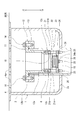
- FIG. 1 is a cross-sectional view illustrating a schematic configuration of a check valve according to the first embodiment.
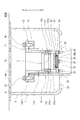
- FIG. 2 is a view corresponding to FIG. 1 illustrating an open state of the check valve according to the first embodiment.
- FIG. 3 is a perspective view showing the spring receiving member of the check valve according to Embodiment 1 as viewed from below.
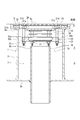
- FIG. 4 is a cross-sectional view illustrating a schematic configuration of a check valve according to the second embodiment.
- Embodiment 1 of the present application will be described with reference to FIGS.
- the check valve 10 of this embodiment is used for the drain funnel 1 provided on the floor of a factory or the like.
- the drain funnel 1 is for discharging fluid such as contaminated water that has been spilled or discharged to the floor.
- the drain funnel 1 includes a storage tank 2 and a discharge pipe 6.
- the storage tank 2 is a container having an upper opening, and is embedded in the floor with the upper opening end being flush with the floor surface.
- the upper opening of the storage tank 2 is closed by a lid 4, and a number of through holes 4 a are formed in the lid 4.
- the storage tank 2 has, for example, a circular shape or a rectangular shape in plan view.
- the discharge pipe 6 extends through the bottom wall 2a of the storage tank 2 so as to extend in the vertical direction. That is, the discharge pipe 6 is provided with the upper end protruding from the bottom wall 2 a of the storage tank 2.
- the fluid discharged to the floor surface flows into the storage tank 2 from the through hole 4 a of the lid 4 and is stored, and the stored fluid is discharged from the discharge pipe 6 to the outside.
- the check valve 10 of the present embodiment is provided in the discharge pipe 6.
- the check valve 10 includes a mounting member 11, a valve seat member 21, a valve body 22, a coil spring 23 (spring), a spring receiving member 24, and a plurality (four in this embodiment) of guide rods 25. It has.
- the attachment member 11 is for attaching the valve seat member 21, the valve body 22 and the like to the discharge pipe 6.
- the attachment member 11 has an insertion member 12 and a screwing member 13.
- the screw member 13 is an annular member having a male screw portion formed on the inner peripheral surface, and is screwed onto the outer periphery of the upper portion of the discharge pipe 6.
- the insertion member 12 has a cylindrical portion 12a extending in the vertical direction and a flange 12b provided at the upper end of the cylindrical portion 12a.
- the cylindrical portion 12 a is formed in a cylindrical shape having a slightly smaller diameter than the inner diameter of the discharge pipe 6, and is inserted into the discharge pipe 6 from above.
- the cylinder portion 12a and the discharge pipe 6 are arranged coaxially.
- the flange 12 b is fixed by the screwing member 13 and the bolt 14 in a state where the cylindrical portion 12 a is inserted into the discharge pipe 6.
- the outer diameter of the flange 12b and the outer diameter of the screwing member 13 are substantially the same.
- the valve seat member 21 is an annular plate member, and is fixed to the lower end surface of the insertion member 12 by a guide rod 25. In the insertion member 12, the lower end portion is thicker than the other portions.
- the outer diameter and inner diameter of the valve seat member 21 are substantially the same as the outer diameter and inner diameter at the lower end of the insertion member 12.
- the opening of the valve seat member 21 and the opening of the cylindrical portion 12a of the insertion member 12 constitute a fluid discharge port 15 (a flow port according to the claims of the present application).
- the valve seat member 21 is an annular valve seat 21a whose inner edge portion slightly protrudes downward (downstream side).
- the valve element 22 is formed in a disc shape.
- the valve body 22 is provided below (downstream side) the valve seat member 21 and opens and closes the discharge port 15 (opening of the valve seat member 21). That is, the valve body 22 closes the discharge port 15 by sitting on the valve seat 21a of the valve seat member 21 (the state shown in FIG. 1), and opens the discharge port 15 by separating from the valve seat 21a (FIG. 2). State shown in).
- the coil spring 23 is provided below (downstream side) the valve body 22 and biases the valve body 22 toward the opening of the valve seat member 21.
- One end of the coil spring 23 is in contact with the lower surface of the valve body 22, and the other end is supported by a spring receiving member 24. That is, the spring receiving member 24 is provided below (on the downstream side) of the coil spring 23, and the other end of the coil spring 23 is inserted into a recess 24a formed in the center.
- the four guide bars 25 are circular bar members.
- the four guide rods 25 are provided so as to extend in the vertical direction (upstream / downstream direction).
- the four guide rods 25 are provided around the valve body 22. Specifically, the four guide rods 25 are arranged at equal intervals (90 ° intervals) in the circumferential direction of the valve body 22.
- the guide rod 25 is inserted into an insertion hole 21 b (around the opening) formed in the valve seat member 21 and then fastened and attached to a screw hole 12 c formed in the insertion member 12.
- Each guide rod 25 attached in this manner is in contact with the outer peripheral surface of the valve body 22 and is configured to guide the valve body 22 in the vertical direction (up-downstream direction). That is, the guide rod 25 restricts the horizontal movement of the valve body 22 and allows only the vertical movement (movement in the vertical direction) of the valve body 22.
- a spring receiving member 24 is attached to the lower end portion (downstream end portion) of the guide rod 25.
- the spring receiving member 24 is formed in a substantially disc shape.
- a male screw portion is formed at the lower end portion of the guide rod 25, and the lower end portion of each guide rod 25 is inserted into the spring receiving member 24 and fixed with a nut 26.
- a plurality of (four in the present embodiment) openings 24c are formed in the bottom wall 24b of the recess 24a receiving the other end of the coil spring 23.
- four cut portions 24d are formed by cutting the outer edge portion between the guide rod 25 and the guide rod 25.
- the opening 24c and the cut portion 24d serve as a fluid flow path.
- the fluid discharged to the floor surface flows into the storage tank 2 from the through hole 4a and is stored.
- the storage surface in the storage tank 2 rises to the upper surface of the insertion member 12, the fluid flows into the insertion member 12.
- the valve body 22 is displaced downward (downstream) and is separated, and the discharge port 15 (valve seat member) 21 opening) opens.
- the fluid of the storage tank 2 is discharged
- the valve body 22 is displaced and seated upward (upstream side), so that the discharge port 15 is closed. Therefore, the back flow of the fluid is prevented.
- the valve body 22 that opens and closes the opening (flow port) of the valve seat member 21 is formed in a plate shape, it is opened and closed with a conventional spherical float (valve body). Compared to the case, the opening of the valve seat member 21 can be enlarged.
- the size of the opening is set to be larger than the size of the float from the viewpoint of preventing the float from entering the opening and being lost. It needs to be quite small.
- the size of the opening of the valve seat member is considerably smaller than the inner diameter of the discharge pipe, and it becomes impossible to earn a discharge amount that matches the inner diameter of the discharge pipe.
- the opening of the valve seat member 21 is closed by the plate-like valve body 22, so that the size of the opening only needs to be slightly smaller than the valve body 22. Thereby, it is possible to earn a sufficient discharge amount that matches the inner diameter of the discharge pipe 6.
- a plurality of guide rods 25 are inserted around the opening of the valve seat member 21 and attached. That is, in the above embodiment, the valve seat member 21 and the guide rod 25 are assembled together. Therefore, the axial center of the opening (flow port) of the valve seat member 21 and the centers of the four guide rods 25 can be accurately aligned. Thereby, the axial center of the opening of the valve seat member 21 and the axial center of the valve body 22 can be accurately aligned. Therefore, the opening of the valve seat member 21 can be reliably closed by the valve body 22. That is, the opening / closing accuracy of the valve body 22 can be increased.
- the axial centers of the valve seat member 21 and the valve body 22 can be accurately aligned. In other words, the axial centers of the valve seat member 21 and the valve body 22 do not shift, so that the opening of the valve seat member 21 (circulation) The size of the mouth) can be made closer to the size of the valve body 22. As a result, the opening of the valve seat member 21 can be made larger, and the amount of fluid discharged can be increased.
- the cutout portion 24d is formed by cutting out the outer edge portion of the spring receiving member 24, the flow area of the fluid can be increased. Thereby, the discharge amount of the fluid can be further earned.
- the position of the spring receiving member 24 (the position in the vertical direction) is adopted. ) Can be adjusted. Thereby, the urging
- the position of the spring receiving member 24 is raised, the urging force by the coil spring 23 is increased, and when the position of the spring receiving member 24 is lowered, the urging force by the coil spring 23 is reduced.
- Embodiment 2 of the present application will be described with reference to FIG.
- the check valve 10 of the present embodiment is configured to be attached to the storage tank 3 in place of the embodiment 1 attached to the discharge pipe 6.
- the drain funnel 1 includes a storage tank 3 and a discharge pipe 7.
- the storage tank 3 is a container having an upper opening, and is embedded in the floor with the upper opening end being flush with the floor surface.
- the upper opening of the storage tank 3 is closed by a lid 5, and a number of through holes 5 a are formed in the lid 5.
- the discharge pipe 7 extends through the bottom wall 3a of the storage tank 3 so as to extend in the vertical direction. That is, as in the first embodiment, the discharge pipe 7 is provided with the upper end protruding from the bottom wall 3 a of the storage tank 3.
- the check valve 10 of this embodiment is attached to the upper opening of the storage tank 3.
- the check valve 10 includes a valve seat member 31, a valve body 33, a coil spring 34 (spring), a spring receiving member 35, and a plurality (six in this embodiment) of guide rods 36. That is, in the present embodiment, unlike the first embodiment, the attachment member is omitted.
- the valve seat member 31 is an annular plate member, and has an inner peripheral base portion 31a and an outer peripheral thin portion 31b. The thin portion 31b is thinner than the base portion 31a.
- the valve seat member 31 has a thin portion 31 b sandwiched between the flange 3 b of the storage tank 3 and the lid 5 and fixed by a flat head screw 32.
- the opening of the valve seat member 31 constitutes an inflow port 30 (a flow port according to the claims of the present application).
- the valve seat member 31 is an annular valve seat 31c whose inner edge portion slightly protrudes downward (downstream).
- the valve element 33 is formed in a disc shape.
- the valve body 33 is provided below (downstream side) the valve seat member 31 and opens and closes the inlet 30 (opening of the valve seat member 31). That is, the valve body 33 closes the inlet 30 by sitting on the valve seat 31c of the valve seat member 31 (the state shown in FIG. 4), and opens the inlet 30 by separating from the valve seat 31c (not shown). ).
- the coil spring 34 is provided below (downstream side) the valve body 33 and biases the valve body 33 toward the inlet 30 (opening of the valve seat member 31).
- One end of the coil spring 34 is in contact with the lower surface of the valve element 33, and the other end is supported by a spring receiving member 35. That is, the spring receiving member 35 is provided below (on the downstream side) of the coil spring 34, and the other end of the coil spring 34 is inserted into a recess 35a formed in the center.
- the six guide rods 36 are circular rod members.
- the six guide rods 36 are provided so as to extend in the vertical direction (upstream / downstream direction).
- Six guide rods 36 are provided around the valve body 33. Specifically, the six guide rods 36 are arranged at equal intervals (60 ° intervals) from each other in the circumferential direction of the valve body 33.
- the guide rod 36 is fastened (inserted) and attached to a screw hole 31 d (around the opening) formed in the valve seat member 31.
- Each guide rod 36 attached in this manner is in contact with the outer peripheral surface of the valve body 33 and is configured to guide the valve body 33 in the vertical direction (up-downstream direction). That is, the guide rod 36 restricts the horizontal movement of the valve element 33 and allows only the vertical movement (movement in the vertical direction) of the valve element 33.
- a spring receiving member 35 is attached to the lower end portion (downstream end portion) of the guide rod 36.
- the spring receiving member 35 is formed in a substantially disk shape.
- a male thread portion is formed at the lower end portion of the guide rod 36, and the spring receiving member 35 is fixed with a nut 37 by inserting the lower end portion of each guide rod 36 into the insertion hole 35 b.
- a plurality of openings are formed in the bottom wall of the recess 35a, and a plurality of outer edges between the guide rod 36 and the guide rod 36 are cut away. An excision is formed. In the spring receiving member 35, these openings and cut portions serve as fluid flow paths.
- the valve element 33 is displaced downward (downstream) and is separated, and the inflow port 30 is opened. .
- the fluid accumulated on the floor flows into the storage tank 3 through the through hole 5 a and the inlet 30.
- a part of the fluid that has flowed into the storage tank 3 is stored in the storage tank 3, and the rest is directly discharged from the discharge pipe 7 to the outside.
- the liquid level of the fluid stored in the storage tank 3 reaches the upper end of the discharge pipe 7, the fluid is discharged from the discharge pipe 7.
- the valve body 33 is displaced and seated upward (upstream side), so the inlet 30 is closed. Therefore, the back flow of the fluid is prevented.
- the same operational effects as those of the first embodiment can be achieved.
- the quantity of the guide rods 25 and 36 is not restricted to what was mentioned above.
- the technology disclosed in the present application is useful for a check valve used in a drain funnel.
Abstract
A check valve (10) is provided with: a plate-shaped valve seat member (21) having a fluid exhaust port (15); a plate-shaped valve body (22) for opening and closing the exhaust port (15), the valve body (22) being provided downstream of the valve seat member (21); a coil spring (23) for urging the valve body (22) toward the exhaust port (15), the coil spring being provided downstream of the valve body (22); a spring-receiving member (24) for receiving the coil spring (23), the spring-receiving member (24) being provided downstream of the coil spring (23) for the coil spring (23); and a plurality of guide rods (25) for guiding the valve body (22) in the upstream/downstream direction, the guide rods (25) being provided around the valve body (22) and being formed so as to extend in the upstream/downstream direction, the downstream-side end parts of the guide rods (25) being attached to the spring-receiving member (24) .
Description
本願は、床等のドレンファンネルに設けられる逆止弁に関する。
This application relates to a check valve provided in a drain funnel such as a floor.
例えば特許文献1に開示されているように、ドレンファンネル(床ドレンファンネル)に設けられる逆止弁が知られている。ドレンファンネルは、工場等の床に設けられ、床面に零れたり排出された汚染水等の流体を外部に排出するためのものである。ドレンファンネルは、床面に埋設される貯留槽(凹部)と、貯留槽の底部に設けられる排出管(排水管)とを有している。そして、排出管に逆止弁が設けられている。逆止弁は、環状の弁座部材と、球状のフロートと、複数のガイド棒(支持ボルト)と、支持部材とを有している。複数のガイド棒は、フロートの周囲に配置され、フロートの上下動をガイドする。支持部材は、各ガイド棒の下端部に設けられ、フロートの下方位置を規制する。この逆止弁では、排出管を流体が逆流する場合、その流体によってフロートが上昇(浮上)して弁座部材に着座する。これにより、流体の逆流が防止される。この逆流時以外の通常時は、フロートは弁座部材から離座して支持部材に支持されている。これにより、床面に排出等された流体が貯留槽に流入して排出管から排出される。
For example, as disclosed in Patent Document 1, a check valve provided in a drain funnel (floor drain funnel) is known. The drain funnel is provided on the floor of a factory or the like, and discharges fluid such as contaminated water that has spilled or discharged to the floor. The drain funnel has a storage tank (concave portion) embedded in the floor and a discharge pipe (drainage pipe) provided at the bottom of the storage tank. A check valve is provided in the discharge pipe. The check valve includes an annular valve seat member, a spherical float, a plurality of guide rods (support bolts), and a support member. The plurality of guide bars are arranged around the float and guide the vertical movement of the float. The support member is provided at the lower end of each guide bar and regulates the lower position of the float. In this check valve, when the fluid flows back through the discharge pipe, the float rises (floats) by the fluid and is seated on the valve seat member. Thereby, the backflow of the fluid is prevented. In normal times other than the reverse flow, the float is separated from the valve seat member and supported by the support member. Thereby, the fluid discharged to the floor surface flows into the storage tank and is discharged from the discharge pipe.
ところで、特許文献1のような逆止弁では、流体の排出量が比較的少なく、十分な排出量を稼ぎたいという要望があった。
By the way, in the check valve as in Patent Document 1, there is a demand for a sufficient amount of fluid discharge and a sufficient amount of fluid discharge.
本願に開示の技術は、かかる事情に鑑みてなされたものであり、その目的は、ドレンファンネルにおいて十分な排出量を稼ぐことができる逆止弁を提供することにある。
The technology disclosed in the present application has been made in view of such circumstances, and an object thereof is to provide a check valve capable of earning a sufficient discharge amount in the drain funnel.
本願に開示の技術は、弁座部材と、弁体と、バネと、バネ受け部材と、複数のガイド棒とを備えている逆止弁に係るものである。上記弁座部材は、流体の流通口を有するものである。上記弁体は、上記弁座部材の下流側に設けられ、上記流通口を開閉する板状のものである。上記バネは、上記弁体の下流側に設けられ、上記弁体を上記流通口へ付勢するものである。上記バネ受け部材は、上記バネの下流側に設けられる該バネのバネ受け部材である。上記複数のガイド棒は、上記弁体の周囲に設けられ且つ上下流方向に延びて形成され、下流側端部に上記バネ受け部材が取り付けられると共に、上記弁体を上下流方向にガイドするものである。
The technology disclosed in the present application relates to a check valve including a valve seat member, a valve body, a spring, a spring receiving member, and a plurality of guide rods. The valve seat member has a fluid circulation port. The said valve body is a plate-shaped thing provided in the downstream of the said valve seat member, and opening and closing the said circulation port. The spring is provided on the downstream side of the valve body, and biases the valve body toward the flow port. The spring receiving member is a spring receiving member of the spring provided on the downstream side of the spring. The plurality of guide rods are provided around the valve body and are formed to extend in the upstream / downstream direction, and the spring receiving member is attached to the downstream end portion and guides the valve body in the upstream / downstream direction. It is.
本願の逆止弁によれば、弁座部材の流通口を開閉する弁体を板状に形成しているため、従来の球状のフロート(弁体)で開閉する場合に比べて、流通口を大きくすることができる。球状のフロートで流通口を開閉する形態(即ち、球面で流通口を閉じる形態)では、フロートが流通口に入り込んで抜けなくなるのを防止する観点から、流通口の大きさはフロートの大きさよりもかなり小さくする必要がある。そのため、例えば配管に逆止弁を設ける場合、配管径に対して流通口の大きさがかなり小さなものとなってしまう。したがって、配管径に合った排出量を稼ぐことができなくなる。この点、本願の逆止弁では、板状の弁体で流通口を閉じるため、流通口の大きさは弁体よりも若干小さくすれば足りる。そのため、配管径に合った十分な排出量を稼ぐことができる。
According to the check valve of the present application, since the valve body that opens and closes the flow port of the valve seat member is formed in a plate shape, the flow port is opened compared to the case of opening and closing with a conventional spherical float (valve body). Can be bigger. In the form in which the circulation port is opened and closed with a spherical float (that is, the form in which the circulation port is closed with a spherical surface), the size of the circulation port is larger than the size of the float from the viewpoint of preventing the float from entering and entering the circulation port. It needs to be quite small. Therefore, for example, when a check valve is provided in the pipe, the size of the flow port is considerably smaller than the pipe diameter. Therefore, it becomes impossible to earn a discharge amount that matches the pipe diameter. In this regard, in the check valve of the present application, since the flow port is closed with a plate-shaped valve body, it is sufficient that the size of the flow port is slightly smaller than that of the valve body. Therefore, it is possible to earn a sufficient discharge amount that matches the pipe diameter.
以下、本願の実施形態について図面を参照しながら説明する。なお、以下の実施形態は、本質的に好ましい例示であって、本願に開示の技術、その適用物、あるいはその用途の範囲を制限することを意図するものではない。
Hereinafter, embodiments of the present application will be described with reference to the drawings. Note that the following embodiments are essentially preferable examples, and are not intended to limit the scope of the technology disclosed in the present application, applications thereof, or uses thereof.
(実施形態1)
本願の実施形態1について図1~図3を参照しながら説明する。本実施形態の逆止弁10は、工場等の床に設けられるドレンファンネル1に用いられるものである。ドレンファンネル1は、床面に零れたり排出された汚染水等の流体を外部に排出するためのものである。 (Embodiment 1)
Embodiment 1 of the present application will be described with reference to FIGS. The check valve 10 of this embodiment is used for the drain funnel 1 provided on the floor of a factory or the like. The drain funnel 1 is for discharging fluid such as contaminated water that has been spilled or discharged to the floor.
本願の実施形態1について図1~図3を参照しながら説明する。本実施形態の逆止弁10は、工場等の床に設けられるドレンファンネル1に用いられるものである。ドレンファンネル1は、床面に零れたり排出された汚染水等の流体を外部に排出するためのものである。 (Embodiment 1)
図1に示すように、ドレンファンネル1は貯留槽2と排出管6を備えている。貯留槽2は、上部が開口した容器であり、上部の開口端が床面と面一となる状態で床に埋設されている。貯留槽2の上部開口は蓋4によって閉じられており、その蓋4には多数の貫通孔4aが形成されている。貯留槽2は、平面視形状が例えば円形や四角形である。排出管6は、上下方向に延びる状態で貯留槽2の底壁2aを貫通して設けられている。つまり、排出管6は上端が貯留槽2の底壁2aから突出した状態で設けられている。ドレンファンネル1では、床面に排出等された流体が蓋4の貫通孔4aから貯留槽2に流入して貯留され、その貯留された流体は排出管6から外部に排出される。
As shown in FIG. 1, the drain funnel 1 includes a storage tank 2 and a discharge pipe 6. The storage tank 2 is a container having an upper opening, and is embedded in the floor with the upper opening end being flush with the floor surface. The upper opening of the storage tank 2 is closed by a lid 4, and a number of through holes 4 a are formed in the lid 4. The storage tank 2 has, for example, a circular shape or a rectangular shape in plan view. The discharge pipe 6 extends through the bottom wall 2a of the storage tank 2 so as to extend in the vertical direction. That is, the discharge pipe 6 is provided with the upper end protruding from the bottom wall 2 a of the storage tank 2. In the drain funnel 1, the fluid discharged to the floor surface flows into the storage tank 2 from the through hole 4 a of the lid 4 and is stored, and the stored fluid is discharged from the discharge pipe 6 to the outside.
図1および図2に示すように、本実施形態の逆止弁10は、排出管6に設けられている。逆止弁10は、取付部材11と、弁座部材21と、弁体22と、コイルバネ23(バネ)と、バネ受け部材24と、複数(本実施形態では、4本)のガイド棒25とを備えている。
1 and 2, the check valve 10 of the present embodiment is provided in the discharge pipe 6. The check valve 10 includes a mounting member 11, a valve seat member 21, a valve body 22, a coil spring 23 (spring), a spring receiving member 24, and a plurality (four in this embodiment) of guide rods 25. It has.
取付部材11は、弁座部材21や弁体22等を排出管6に取り付けるためのものである。取付部材11は、挿入部材12と螺合部材13を有している。螺合部材13は、内周面に雄ねじ部が形成された環状部材であり、排出管6の上部の外周に螺合して取り付けられている。挿入部材12は、上下方向に延びる筒部12aと、筒部12aの上端に設けられたフランジ12bとを有している。筒部12aは、排出管6の内径よりもやや小径の円筒状に形成されており、排出管6に上方から挿入されている。筒部12aと排出管6とは同軸に配置されている。挿入部材12は、筒部12aが排出管6に挿入された状態で、フランジ12bが螺合部材13とボルト14によって固定される。なお、フランジ12bの外径と螺合部材13の外径は略同一である。
The attachment member 11 is for attaching the valve seat member 21, the valve body 22 and the like to the discharge pipe 6. The attachment member 11 has an insertion member 12 and a screwing member 13. The screw member 13 is an annular member having a male screw portion formed on the inner peripheral surface, and is screwed onto the outer periphery of the upper portion of the discharge pipe 6. The insertion member 12 has a cylindrical portion 12a extending in the vertical direction and a flange 12b provided at the upper end of the cylindrical portion 12a. The cylindrical portion 12 a is formed in a cylindrical shape having a slightly smaller diameter than the inner diameter of the discharge pipe 6, and is inserted into the discharge pipe 6 from above. The cylinder portion 12a and the discharge pipe 6 are arranged coaxially. In the insertion member 12, the flange 12 b is fixed by the screwing member 13 and the bolt 14 in a state where the cylindrical portion 12 a is inserted into the discharge pipe 6. In addition, the outer diameter of the flange 12b and the outer diameter of the screwing member 13 are substantially the same.
弁座部材21は、円環状の板部材であり、挿入部材12の下端面にガイド棒25によって固定されている。挿入部材12では、下端部が他の部分よりも肉厚が厚くなっている。弁座部材21の外径および内径は、挿入部材12の下端部における外径および内径と略同一である。弁座部材21の開口は、挿入部材12の筒部12aの開口と共に流体の排出口15(本願の請求項に係る流通口)を構成している。弁座部材21では、内縁部が下方(下流側)に若干突出した円環状の弁座21aとなっている。
The valve seat member 21 is an annular plate member, and is fixed to the lower end surface of the insertion member 12 by a guide rod 25. In the insertion member 12, the lower end portion is thicker than the other portions. The outer diameter and inner diameter of the valve seat member 21 are substantially the same as the outer diameter and inner diameter at the lower end of the insertion member 12. The opening of the valve seat member 21 and the opening of the cylindrical portion 12a of the insertion member 12 constitute a fluid discharge port 15 (a flow port according to the claims of the present application). The valve seat member 21 is an annular valve seat 21a whose inner edge portion slightly protrudes downward (downstream side).
弁体22は、円板状に形成されている。弁体22は、弁座部材21の下方(下流側)に設けられて、排出口15(弁座部材21の開口)を開閉するものである。つまり、弁体22は、弁座部材21の弁座21aに着座することで排出口15を閉じ(図1に示す状態)、弁座21aから離座することで排出口15を開く(図2に示す状態)。
The valve element 22 is formed in a disc shape. The valve body 22 is provided below (downstream side) the valve seat member 21 and opens and closes the discharge port 15 (opening of the valve seat member 21). That is, the valve body 22 closes the discharge port 15 by sitting on the valve seat 21a of the valve seat member 21 (the state shown in FIG. 1), and opens the discharge port 15 by separating from the valve seat 21a (FIG. 2). State shown in).
コイルバネ23は、弁体22の下方(下流側)に設けられ、弁体22を弁座部材21の開口へ付勢するものである。コイルバネ23は、一端が弁体22の下面に接し、他端がバネ受け部材24によって支持されている。つまり、バネ受け部材24は、コイルバネ23の下方(下流側)に設けられており、中央に形成された凹部24aにコイルバネ23の他端が挿入されている。
The coil spring 23 is provided below (downstream side) the valve body 22 and biases the valve body 22 toward the opening of the valve seat member 21. One end of the coil spring 23 is in contact with the lower surface of the valve body 22, and the other end is supported by a spring receiving member 24. That is, the spring receiving member 24 is provided below (on the downstream side) of the coil spring 23, and the other end of the coil spring 23 is inserted into a recess 24a formed in the center.
4つのガイド棒25は、円形の棒部材である。4つのガイド棒25は、上下方向(上下流方向)に延びる状態で設けられている。4つのガイド棒25は、弁体22の周囲に設けられている。具体的に、4つのガイド棒25は弁体22の周方向において互いに等間隔(90°間隔)で配置されている。ガイド棒25は、弁座部材21に形成された挿通孔21b(開口の周囲)に挿入された後、挿入部材12に形成されたネジ孔12cに締結されて取り付けられている。こうして取り付けられた各ガイド棒25は、弁体22の外周面と接しており、弁体22を上下方向(上下流方向)にガイドするように構成されている。つまり、ガイド棒25は、弁体22の水平方向の動作を規制し、弁体22の上下動(上下方向の移動)のみを許容している。
The four guide bars 25 are circular bar members. The four guide rods 25 are provided so as to extend in the vertical direction (upstream / downstream direction). The four guide rods 25 are provided around the valve body 22. Specifically, the four guide rods 25 are arranged at equal intervals (90 ° intervals) in the circumferential direction of the valve body 22. The guide rod 25 is inserted into an insertion hole 21 b (around the opening) formed in the valve seat member 21 and then fastened and attached to a screw hole 12 c formed in the insertion member 12. Each guide rod 25 attached in this manner is in contact with the outer peripheral surface of the valve body 22 and is configured to guide the valve body 22 in the vertical direction (up-downstream direction). That is, the guide rod 25 restricts the horizontal movement of the valve body 22 and allows only the vertical movement (movement in the vertical direction) of the valve body 22.
また、ガイド棒25の下端部(下流側端部)には、バネ受け部材24が取り付けられている。バネ受け部材24は、略円板状に形成されている。図3にも示すように、ガイド棒25の下端部には雄ねじ部が形成されており、バネ受け部材24は各ガイド棒25の下端部が挿入されてナット26で固定されている。バネ受け部材24では、コイルバネ23の他端を受けている凹部24aの底壁24bに複数(本実施形態では、4つ)の開口24cが形成されている。また、バネ受け部材24では、ガイド棒25とガイド棒25との間の外縁部が切除されてなる4つの切除部24dが形成されている。バネ受け部材24では、これら開口24cおよび切除部24dが流体の流通路となっている。
Further, a spring receiving member 24 is attached to the lower end portion (downstream end portion) of the guide rod 25. The spring receiving member 24 is formed in a substantially disc shape. As shown in FIG. 3, a male screw portion is formed at the lower end portion of the guide rod 25, and the lower end portion of each guide rod 25 is inserted into the spring receiving member 24 and fixed with a nut 26. In the spring receiving member 24, a plurality of (four in the present embodiment) openings 24c are formed in the bottom wall 24b of the recess 24a receiving the other end of the coil spring 23. In the spring receiving member 24, four cut portions 24d are formed by cutting the outer edge portion between the guide rod 25 and the guide rod 25. In the spring receiving member 24, the opening 24c and the cut portion 24d serve as a fluid flow path.
上述したドレンファンネル1では、床面に排出等された流体は貫通孔4aから貯留槽2に流入して貯留される。貯留槽2内の貯留面が挿入部材12の上面まで上昇すると、流体が挿入部材12内に流入する。そして、挿入部材12内において液面が所定高さ(例えば、挿入部材12の上面)まで上昇すると、弁体22が下方(下流側)へ変位して離座し、排出口15(弁座部材21の開口)が開く。これにより、貯留槽2の流体が排出管6から外部に排出される。また、排出管6において流体が逆流する場合、弁体22は上方(上流側)へ変位して着座するため、排出口15は閉じている。したがって、流体の逆流が防止される。
In the drain funnel 1 described above, the fluid discharged to the floor surface flows into the storage tank 2 from the through hole 4a and is stored. When the storage surface in the storage tank 2 rises to the upper surface of the insertion member 12, the fluid flows into the insertion member 12. Then, when the liquid level rises to a predetermined height (for example, the upper surface of the insertion member 12) in the insertion member 12, the valve body 22 is displaced downward (downstream) and is separated, and the discharge port 15 (valve seat member) 21 opening) opens. Thereby, the fluid of the storage tank 2 is discharged | emitted from the discharge pipe 6 outside. Further, when the fluid flows backward in the discharge pipe 6, the valve body 22 is displaced and seated upward (upstream side), so that the discharge port 15 is closed. Therefore, the back flow of the fluid is prevented.
上記実施形態の逆止弁10によれば、弁座部材21の開口(流通口)を開閉する弁体22を板状に形成しているため、従来の球状のフロート(弁体)で開閉する場合に比べて、弁座部材21の開口を大きくすることができる。球状のフロートで弁座部材の開口を開閉する形態(即ち、球面で開口を閉じる形態)では、フロートが開口に入り込んで抜けなくなるのを防止する観点から、開口の大きさをフロートの大きさよりもかなり小さくする必要がある。そのため、排出管の内径に対して弁座部材の開口の大きさがかなり小さなものとなってしまい、排出管の内径に合った排出量を稼ぐことができなくなる。これに対し、上記実施形態の逆止弁10では、板状の弁体22で弁座部材21の開口を閉じるため、その開口の大きさは弁体22よりも若干小さくすれば足りる。これによって、排出管6の内径に合った十分な排出量を稼ぐことができる。
According to the check valve 10 of the above embodiment, since the valve body 22 that opens and closes the opening (flow port) of the valve seat member 21 is formed in a plate shape, it is opened and closed with a conventional spherical float (valve body). Compared to the case, the opening of the valve seat member 21 can be enlarged. In the form in which the opening of the valve seat member is opened and closed with a spherical float (that is, the form in which the opening is closed with a spherical surface), the size of the opening is set to be larger than the size of the float from the viewpoint of preventing the float from entering the opening and being lost. It needs to be quite small. Therefore, the size of the opening of the valve seat member is considerably smaller than the inner diameter of the discharge pipe, and it becomes impossible to earn a discharge amount that matches the inner diameter of the discharge pipe. On the other hand, in the check valve 10 of the above-described embodiment, the opening of the valve seat member 21 is closed by the plate-like valve body 22, so that the size of the opening only needs to be slightly smaller than the valve body 22. Thereby, it is possible to earn a sufficient discharge amount that matches the inner diameter of the discharge pipe 6.
また、上記実施形態の逆止弁10によれば、複数のガイド棒25を弁座部材21の開口の周囲に挿入して取り付けるようにした。つまり、上記実施形態では、弁座部材21とガイド棒25とを一体に組み付けるようにした。そのため、弁座部材21の開口(流通口)の軸心と4つのガイド棒25の中心とを正確に合わせることができる。これにより、弁座部材21の開口の軸心と弁体22の軸心とを正確に合わせることができる。したがって、確実に弁座部材21の開口を弁体22で閉じることができる。つまり、弁体22の開閉精度を高めることができる。
Further, according to the check valve 10 of the above-described embodiment, a plurality of guide rods 25 are inserted around the opening of the valve seat member 21 and attached. That is, in the above embodiment, the valve seat member 21 and the guide rod 25 are assembled together. Therefore, the axial center of the opening (flow port) of the valve seat member 21 and the centers of the four guide rods 25 can be accurately aligned. Thereby, the axial center of the opening of the valve seat member 21 and the axial center of the valve body 22 can be accurately aligned. Therefore, the opening of the valve seat member 21 can be reliably closed by the valve body 22. That is, the opening / closing accuracy of the valve body 22 can be increased.
また、弁座部材21と弁体22との軸心を正確に合わせることができる、言い換えれば、弁座部材21と弁体22との軸心がずれないため、弁座部材21の開口(流通口)の大きさを弁体22の大きさにより近づけることが可能になる。これによって、弁座部材21の開口をより大きくすることができ、流体の排出量を増大させることができる。
Further, the axial centers of the valve seat member 21 and the valve body 22 can be accurately aligned. In other words, the axial centers of the valve seat member 21 and the valve body 22 do not shift, so that the opening of the valve seat member 21 (circulation) The size of the mouth) can be made closer to the size of the valve body 22. As a result, the opening of the valve seat member 21 can be made larger, and the amount of fluid discharged can be increased.
また、上記実施形態の逆止弁10では、バネ受け部材24において外縁部を切除してなる切除部24dを形成しているため、流体の流通面積を稼ぐことができる。これにより、流体の排出量をより稼ぐことができる。
Further, in the check valve 10 of the above embodiment, since the cutout portion 24d is formed by cutting out the outer edge portion of the spring receiving member 24, the flow area of the fluid can be increased. Thereby, the discharge amount of the fluid can be further earned.
また、上記実施形態の逆止弁10では、バネ受け部材24をガイド棒25の下端部に挿入してナット26で固定する構成を採っているため、バネ受け部材24の位置(上下方向における位置)を調整することが可能である。これにより、コイルバネ23による弁体22への付勢力を容易に調整することができる。バネ受け部材24の位置を上げるとコイルバネ23による付勢力は大きくなり、バネ受け部材24の位置を下げるとコイルバネ23による付勢力は小さくなる。
In the check valve 10 of the above embodiment, since the spring receiving member 24 is inserted into the lower end portion of the guide rod 25 and fixed with the nut 26, the position of the spring receiving member 24 (the position in the vertical direction) is adopted. ) Can be adjusted. Thereby, the urging | biasing force to the valve body 22 by the coil spring 23 can be adjusted easily. When the position of the spring receiving member 24 is raised, the urging force by the coil spring 23 is increased, and when the position of the spring receiving member 24 is lowered, the urging force by the coil spring 23 is reduced.
(実施形態2)
本願の実施形態2について図4を参照しながら説明する。本実施形態の逆止弁10は、上記実施形態1が排出管6に取り付けるようにしたのに代えて、貯留槽3に取り付けるようにしたものである。 (Embodiment 2)
Embodiment 2 of the present application will be described with reference to FIG. The check valve 10 of the present embodiment is configured to be attached to the storage tank 3 in place of the embodiment 1 attached to the discharge pipe 6.
本願の実施形態2について図4を参照しながら説明する。本実施形態の逆止弁10は、上記実施形態1が排出管6に取り付けるようにしたのに代えて、貯留槽3に取り付けるようにしたものである。 (Embodiment 2)
図4に示すように、本実施形態においても、ドレンファンネル1は貯留槽3と排出管7を備えている。貯留槽3は、上部が開口した容器であり、上部の開口端が床面と面一となる状態で床に埋設されている。貯留槽3の上部開口は蓋5によって閉じられており、その蓋5には多数の貫通孔5aが形成されている。排出管7は、上下方向に延びる状態で貯留槽3の底壁3aを貫通して設けられている。つまり、上記実施形態1と同様、排出管7は上端が貯留槽3の底壁3aから突出した状態で設けられている。
As shown in FIG. 4, also in this embodiment, the drain funnel 1 includes a storage tank 3 and a discharge pipe 7. The storage tank 3 is a container having an upper opening, and is embedded in the floor with the upper opening end being flush with the floor surface. The upper opening of the storage tank 3 is closed by a lid 5, and a number of through holes 5 a are formed in the lid 5. The discharge pipe 7 extends through the bottom wall 3a of the storage tank 3 so as to extend in the vertical direction. That is, as in the first embodiment, the discharge pipe 7 is provided with the upper end protruding from the bottom wall 3 a of the storage tank 3.
本実施形態の逆止弁10は、貯留槽3の上部開口に取り付けられている。逆止弁10は、弁座部材31と、弁体33と、コイルバネ34(バネ)と、バネ受け部材35と、複数(本実施形態では、6本)のガイド棒36とを備えている。つまり、本実施形態では、上記実施形態1と異なり、取付部材が省略されている。
The check valve 10 of this embodiment is attached to the upper opening of the storage tank 3. The check valve 10 includes a valve seat member 31, a valve body 33, a coil spring 34 (spring), a spring receiving member 35, and a plurality (six in this embodiment) of guide rods 36. That is, in the present embodiment, unlike the first embodiment, the attachment member is omitted.
弁座部材31は、円環状の板部材であり、内周側の基部31aと外周側の薄肉部31bとを有している。薄肉部31bは、基部31aよりも肉厚が薄くなっている。弁座部材31は、薄肉部31bが貯留槽3のフランジ3bと蓋5とに挟まれて皿ネジ32で固定されている。弁座部材31の開口は、流入口30(本願の請求項に係る流通口)を構成している。弁座部材31では、内縁部が下方(下流側)に若干突出した円環状の弁座31cとなっている。
The valve seat member 31 is an annular plate member, and has an inner peripheral base portion 31a and an outer peripheral thin portion 31b. The thin portion 31b is thinner than the base portion 31a. The valve seat member 31 has a thin portion 31 b sandwiched between the flange 3 b of the storage tank 3 and the lid 5 and fixed by a flat head screw 32. The opening of the valve seat member 31 constitutes an inflow port 30 (a flow port according to the claims of the present application). The valve seat member 31 is an annular valve seat 31c whose inner edge portion slightly protrudes downward (downstream).
弁体33は、円板状に形成されている。弁体33は、弁座部材31の下方(下流側)に設けられて、流入口30(弁座部材31の開口)を開閉するものである。つまり、弁体33は、弁座部材31の弁座31cに着座することで流入口30を閉じ(図4に示す状態)、弁座31cから離座することで流入口30を開く(図示省略)。
The valve element 33 is formed in a disc shape. The valve body 33 is provided below (downstream side) the valve seat member 31 and opens and closes the inlet 30 (opening of the valve seat member 31). That is, the valve body 33 closes the inlet 30 by sitting on the valve seat 31c of the valve seat member 31 (the state shown in FIG. 4), and opens the inlet 30 by separating from the valve seat 31c (not shown). ).
コイルバネ34は、弁体33の下方(下流側)に設けられ、弁体33を流入口30(弁座部材31の開口)へ付勢するものである。コイルバネ34は、一端が弁体33の下面に接し、他端がバネ受け部材35によって支持されている。つまり、バネ受け部材35は、コイルバネ34の下方(下流側)に設けられており、中央に形成された凹部35aにコイルバネ34の他端が挿入されている。
The coil spring 34 is provided below (downstream side) the valve body 33 and biases the valve body 33 toward the inlet 30 (opening of the valve seat member 31). One end of the coil spring 34 is in contact with the lower surface of the valve element 33, and the other end is supported by a spring receiving member 35. That is, the spring receiving member 35 is provided below (on the downstream side) of the coil spring 34, and the other end of the coil spring 34 is inserted into a recess 35a formed in the center.
6つのガイド棒36は、円形の棒部材である。6つのガイド棒36は、上下方向(上下流方向)に延びる状態で設けられている。6つのガイド棒36は、弁体33の周囲に設けられている。具体的に、6つのガイド棒36は弁体33の周方向において互いに等間隔(60°間隔)で配置されている。ガイド棒36は、弁座部材31に形成されたネジ孔31d(開口の周囲)に締結されて(挿入されて)取り付けられている。こうして取り付けられた各ガイド棒36は、弁体33の外周面と接しており、弁体33を上下方向(上下流方向)にガイドするように構成されている。つまり、ガイド棒36は、弁体33の水平方向の動作を規制し、弁体33の上下動(上下方向の移動)のみを許容している。
The six guide rods 36 are circular rod members. The six guide rods 36 are provided so as to extend in the vertical direction (upstream / downstream direction). Six guide rods 36 are provided around the valve body 33. Specifically, the six guide rods 36 are arranged at equal intervals (60 ° intervals) from each other in the circumferential direction of the valve body 33. The guide rod 36 is fastened (inserted) and attached to a screw hole 31 d (around the opening) formed in the valve seat member 31. Each guide rod 36 attached in this manner is in contact with the outer peripheral surface of the valve body 33 and is configured to guide the valve body 33 in the vertical direction (up-downstream direction). That is, the guide rod 36 restricts the horizontal movement of the valve element 33 and allows only the vertical movement (movement in the vertical direction) of the valve element 33.
また、上記実施形態1と同様、ガイド棒36の下端部(下流側端部)には、バネ受け部材35が取り付けられている。バネ受け部材35は、略円板状に形成されている。ガイド棒36の下端部には雄ねじ部が形成されており、バネ受け部材35はその挿通孔35bに各ガイド棒36の下端部が挿入されてナット37で固定されている。また、図示しないが、本実施形態のバネ受け部材35においても、凹部35aの底壁に複数の開口が形成され、ガイド棒36とガイド棒36との間の外縁部が切除されてなる複数の切除部が形成されている。バネ受け部材35では、これら開口および切除部が流体の流通路となっている。
Further, as in the first embodiment, a spring receiving member 35 is attached to the lower end portion (downstream end portion) of the guide rod 36. The spring receiving member 35 is formed in a substantially disk shape. A male thread portion is formed at the lower end portion of the guide rod 36, and the spring receiving member 35 is fixed with a nut 37 by inserting the lower end portion of each guide rod 36 into the insertion hole 35 b. Although not shown, in the spring receiving member 35 of the present embodiment, a plurality of openings are formed in the bottom wall of the recess 35a, and a plurality of outer edges between the guide rod 36 and the guide rod 36 are cut away. An excision is formed. In the spring receiving member 35, these openings and cut portions serve as fluid flow paths.
本実施形態のドレンファンネル1では、床面に排出等された流体の液面が所定高さに達すると、弁体33が下方(下流側)へ変位して離座し、流入口30が開く。これにより、床面に溜まっている流体は貫通孔5aおよび流入口30を介して貯留槽3に流入する。貯留槽3に流入した流体の一部は貯留槽3内に貯留され、残りはそのまま排出管7から外部に排出される。貯留槽3内に貯留された流体の液面が排出管7の上端まで達すると、流体は排出管7から排出される。また、排出管7において流体が逆流する場合、弁体33は上方(上流側)へ変位して着座するため、流入口30は閉じている。したがって、流体の逆流が防止される。本実施形態の逆止弁10においても、上記実施形態1と同様の作用効果を奏することができる。
In the drain funnel 1 of the present embodiment, when the level of the fluid discharged to the floor surface reaches a predetermined height, the valve element 33 is displaced downward (downstream) and is separated, and the inflow port 30 is opened. . Thereby, the fluid accumulated on the floor flows into the storage tank 3 through the through hole 5 a and the inlet 30. A part of the fluid that has flowed into the storage tank 3 is stored in the storage tank 3, and the rest is directly discharged from the discharge pipe 7 to the outside. When the liquid level of the fluid stored in the storage tank 3 reaches the upper end of the discharge pipe 7, the fluid is discharged from the discharge pipe 7. When the fluid flows backward in the discharge pipe 7, the valve body 33 is displaced and seated upward (upstream side), so the inlet 30 is closed. Therefore, the back flow of the fluid is prevented. Also in the check valve 10 of the present embodiment, the same operational effects as those of the first embodiment can be achieved.
なお、上述した各実施形態において、ガイド棒25,36の数量は上述したものに限らない。
In addition, in each embodiment mentioned above, the quantity of the guide rods 25 and 36 is not restricted to what was mentioned above.
本願に開示の技術は、ドレンファンネルに用いられる逆止弁について有用である。
The technology disclosed in the present application is useful for a check valve used in a drain funnel.
10 逆止弁
15 排出口(流通口、開口)
30 流入口(流通口、開口)
21,31 弁座部材
22,33 弁体
23,34 コイルバネ
24,35 バネ受け部材
25,36 ガイド棒
10Check valve 15 Discharge port (distribution port, opening)
30 Inlet (distribution port, opening)
21 and 31 Valve seat members 22 and 33 Valve bodies 23 and 34 Coil springs 24 and 35 Spring receiving members 25 and 36 Guide rods
15 排出口(流通口、開口)
30 流入口(流通口、開口)
21,31 弁座部材
22,33 弁体
23,34 コイルバネ
24,35 バネ受け部材
25,36 ガイド棒
10
30 Inlet (distribution port, opening)
21 and 31
Claims (2)
- 流体の流通口を有する弁座部材と、
上記弁座部材の下流側に設けられ、上記流通口を開閉する板状の弁体と、
上記弁体の下流側に設けられ、上記弁体を上記流通口へ付勢するバネと、
上記バネの下流側に設けられる該バネのバネ受け部材と、
上記弁体の周囲に設けられ且つ上下流方向に延びて形成され、下流側端部に上記バネ受け部材が取り付けられると共に、上記弁体を上下流方向にガイドする複数のガイド棒とを備えている
ことを特徴とする逆止弁。 A valve seat member having a fluid circulation port;
A plate-like valve body that is provided on the downstream side of the valve seat member and opens and closes the flow port;
A spring provided on the downstream side of the valve body, and biasing the valve body toward the flow port;
A spring receiving member of the spring provided on the downstream side of the spring;
A plurality of guide rods provided around the valve body and extending in the upstream / downstream direction, the spring receiving member being attached to the downstream end portion, and guiding the valve body in the upstream / downstream direction. A check valve characterized by - 請求項1に記載の逆止弁において、
上記複数のガイド棒は、上流側端部が上記弁座部材の流通口の周囲に挿入されている
ことを特徴とする逆止弁。
The check valve according to claim 1,
The check valve, wherein the plurality of guide rods have upstream end portions inserted around a circulation port of the valve seat member.
Priority Applications (3)
| Application Number | Priority Date | Filing Date | Title |
|---|---|---|---|
| JP2016560218A JP6585619B2 (en) | 2014-11-17 | 2015-11-16 | Check valve |
| EP15860418.1A EP3222894B1 (en) | 2014-11-17 | 2015-11-16 | Check valve |
| US15/595,046 US10436334B2 (en) | 2014-11-17 | 2017-05-15 | Check valve |
Applications Claiming Priority (2)
| Application Number | Priority Date | Filing Date | Title |
|---|---|---|---|
| JP2014232685 | 2014-11-17 | ||
| JP2014-232685 | 2014-11-17 |
Related Child Applications (1)
| Application Number | Title | Priority Date | Filing Date |
|---|---|---|---|
| US15/595,046 Continuation US10436334B2 (en) | 2014-11-17 | 2017-05-15 | Check valve |
Publications (1)
| Publication Number | Publication Date |
|---|---|
| WO2016080359A1 true WO2016080359A1 (en) | 2016-05-26 |
Family
ID=56013896
Family Applications (1)
| Application Number | Title | Priority Date | Filing Date |
|---|---|---|---|
| PCT/JP2015/082146 WO2016080359A1 (en) | 2014-11-17 | 2015-11-16 | Check valve |
Country Status (4)
| Country | Link |
|---|---|
| US (1) | US10436334B2 (en) |
| EP (1) | EP3222894B1 (en) |
| JP (1) | JP6585619B2 (en) |
| WO (1) | WO2016080359A1 (en) |
Families Citing this family (2)
| Publication number | Priority date | Publication date | Assignee | Title |
|---|---|---|---|---|
| MX2019006590A (en) | 2018-06-07 | 2019-12-09 | The Bentley Group Ltd | Flow control valve. |
| AU2020206188A1 (en) * | 2019-01-09 | 2021-08-26 | Physiclean Ltd. | Drain pipe connector system |
Citations (3)
| Publication number | Priority date | Publication date | Assignee | Title |
|---|---|---|---|---|
| JPS6078987U (en) * | 1983-11-07 | 1985-06-01 | ダイキン工業株式会社 | Check valve for compressor |
| JP2003301954A (en) * | 2002-04-11 | 2003-10-24 | Ishizaki Seisakusho:Kk | Check valve and manufacturing method thereof |
| JP2005054954A (en) * | 2003-08-07 | 2005-03-03 | Tokyo Keiso Co Ltd | Control valve |
Family Cites Families (25)
| Publication number | Priority date | Publication date | Assignee | Title |
|---|---|---|---|---|
| US2254209A (en) * | 1941-09-02 | Valve | ||
| US886045A (en) * | 1906-03-06 | 1908-04-28 | Herman J Ehrlich | Valve. |
| US2649277A (en) * | 1949-11-25 | 1953-08-18 | Durabla Mfg Co | Check valve |
| US2694411A (en) * | 1950-07-01 | 1954-11-16 | Neyrpic Ets | Self-centering valve with spring of slight lateral stability |
| US2710023A (en) * | 1951-08-22 | 1955-06-07 | Durabla Mfg Company | Check-unit or valve |
| US2965126A (en) * | 1958-08-04 | 1960-12-20 | Holly Mfg Inc | Automatic floor drain shut-off valves |
| US3084709A (en) * | 1960-05-19 | 1963-04-09 | Flick Reedy Corp | Removable check unit |
| AT239426B (en) * | 1963-07-04 | 1965-04-12 | Enfo Grundlagen Forschungs Ag | Automatic valve, especially for reciprocating compressors |
| US3461905A (en) * | 1968-07-03 | 1969-08-19 | Daniel U Mccabe | Lifetime check valve for gasoline dispensing equipment |
| US3913615A (en) * | 1973-10-18 | 1975-10-21 | Pall Corp | Flat-lapped valve cartridge assembly with caged poppet |
| US4140148A (en) * | 1976-11-18 | 1979-02-20 | The Coca-Cola Company | Pressure relief valve for product containers |
| JPS55166952U (en) * | 1979-05-18 | 1980-12-01 | ||
| US5010916A (en) * | 1990-03-23 | 1991-04-30 | Albrecht David E | Check valve |
| US5193579A (en) * | 1990-06-23 | 1993-03-16 | Filterwerk Mann & Hummel Gmbh | Internal combustion engine lubricating oil filter valve |
| US5546981A (en) * | 1995-01-12 | 1996-08-20 | Gilbarco, Inc. | Check valve |
| SE507492C2 (en) * | 1996-10-30 | 1998-06-15 | Split Vision Dev Ab | Floor well with duct means for ventilation |
| DE19823310A1 (en) * | 1998-05-26 | 1999-12-02 | Karl Adolf Zenner Wasserzaehle | Compound water meter |
| JP2000346241A (en) * | 1999-06-07 | 2000-12-15 | Toyota Autom Loom Works Ltd | Check valve |
| DE102004033022A1 (en) * | 2004-07-08 | 2006-02-02 | Ina-Schaeffler Kg | check valve |
| DE102006016317A1 (en) * | 2006-04-06 | 2007-10-11 | Knorr-Bremse Systeme für Schienenfahrzeuge GmbH | Compressor arrangement with a valve unit in the intake area |
| DE102007039025A1 (en) * | 2007-08-17 | 2009-02-19 | Ritag Ritterhuder Armaturen Gmbh & Co. Armaturenwerk Kg | Device for blocking the flow of fluid media in pipes, hoses or the like, in particular check valve |
| JP2013185386A (en) * | 2012-03-09 | 2013-09-19 | Tokyo Energy & Systems Inc | Floor drain funnel |
| US9278641B2 (en) * | 2013-01-18 | 2016-03-08 | Hai Van Do Van | Valve for rapid inflation and deflation |
| CN203082279U (en) * | 2013-01-29 | 2013-07-24 | 四川港通医疗设备集团股份有限公司 | Vacuum check valve |
| US9242078B2 (en) * | 2013-04-22 | 2016-01-26 | King Abdulaziz University | CSF shunt valve |
-
2015
- 2015-11-16 EP EP15860418.1A patent/EP3222894B1/en active Active
- 2015-11-16 WO PCT/JP2015/082146 patent/WO2016080359A1/en active Application Filing
- 2015-11-16 JP JP2016560218A patent/JP6585619B2/en active Active
-
2017
- 2017-05-15 US US15/595,046 patent/US10436334B2/en active Active
Patent Citations (3)
| Publication number | Priority date | Publication date | Assignee | Title |
|---|---|---|---|---|
| JPS6078987U (en) * | 1983-11-07 | 1985-06-01 | ダイキン工業株式会社 | Check valve for compressor |
| JP2003301954A (en) * | 2002-04-11 | 2003-10-24 | Ishizaki Seisakusho:Kk | Check valve and manufacturing method thereof |
| JP2005054954A (en) * | 2003-08-07 | 2005-03-03 | Tokyo Keiso Co Ltd | Control valve |
Also Published As
| Publication number | Publication date |
|---|---|
| EP3222894A1 (en) | 2017-09-27 |
| EP3222894B1 (en) | 2020-08-26 |
| US20170248242A1 (en) | 2017-08-31 |
| US10436334B2 (en) | 2019-10-08 |
| JPWO2016080359A1 (en) | 2017-08-31 |
| JP6585619B2 (en) | 2019-10-02 |
| EP3222894A4 (en) | 2018-07-11 |
Similar Documents
| Publication | Publication Date | Title |
|---|---|---|
| JP5048482B2 (en) | Drain trap | |
| US7614420B2 (en) | Autofeed mechanism for heated humidifier chamber | |
| US20060201557A1 (en) | Ball check valve | |
| JP6640009B2 (en) | Backflow prevention device | |
| US20180283685A1 (en) | Non-Return Valve for Flue Gas Venting and Damper Assembly for Use Therein | |
| JP6295905B2 (en) | Fuel shut-off valve | |
| US20110079291A1 (en) | Valve | |
| CN106715177B (en) | Exacerbation baffle and spline orifice plate for exhaust valve | |
| JP6585619B2 (en) | Check valve | |
| US8490642B2 (en) | Fuel-outflow check valve | |
| US8776823B2 (en) | Fuel shut-off valves | |
| JP2006290085A (en) | Seal structure of float valve | |
| JP6040201B2 (en) | Floor drain funnel | |
| JP2012125708A (en) | Oil-water separator | |
| JP5416463B2 (en) | Exhaust valve | |
| JP6726952B2 (en) | Check valve | |
| KR20220091482A (en) | valve device | |
| JP7092640B2 (en) | Float check valve | |
| JP7152253B2 (en) | Float check valve | |
| JP2020112165A (en) | Float-type check valve | |
| US20220194216A1 (en) | Over-fueling prevention valve | |
| WO2020213231A1 (en) | Float check valve | |
| JP6737980B1 (en) | Float check valve | |
| KR200484932Y1 (en) | Back draft valve apparatus for washing suplier of Toilet Bowl | |
| US573005A (en) | Self-watering trough |
Legal Events
| Date | Code | Title | Description |
|---|---|---|---|
| 121 | Ep: the epo has been informed by wipo that ep was designated in this application |
Ref document number: 15860418 Country of ref document: EP Kind code of ref document: A1 |
|
| ENP | Entry into the national phase |
Ref document number: 2016560218 Country of ref document: JP Kind code of ref document: A |
|
| REEP | Request for entry into the european phase |
Ref document number: 2015860418 Country of ref document: EP |
|
| NENP | Non-entry into the national phase |
Ref country code: DE |