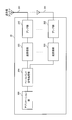
図1は、非ライセンスバンドでLTEを運用する無線通信システム(LTE-U)の運用形態の一例を示している。図1に示すように、LTEを非ライセンスバンドで用いるシナリオとして、キャリアアグリゲーション(CA:Carrier Aggregation)、デュアルコネクティビティ(DC:Dual Connectivity)又はスタンドアローン(SA:Stand Alone)などの複数のシナリオが想定される。
FIG. 1 shows an example of an operation mode of a radio communication system (LTE-U) that operates LTE in a non-licensed band. As shown in Fig. 1, multiple scenarios such as Carrier Aggregation (CA), Dual Connectivity (DC) or Stand Alone (SA) are assumed as scenarios in which LTE is used in a non-licensed band. Is done.
図1Aは、ライセンスバンド及び非ライセンスバンドを用いて、キャリアアグリゲーション(CA)を適用するシナリオを示している。CAは、複数の周波数ブロック(コンポーネントキャリア(CC:Component Carrier)、セルとも呼ぶ)を利用して広帯域化する技術である。
FIG. 1A shows a scenario in which carrier aggregation (CA) is applied using a licensed band and a non-licensed band. CA is a technology that uses a plurality of frequency blocks (also referred to as a component carrier (CC) or a cell) to increase the bandwidth.
図1Aに示す例では、ライセンスバンドを利用するマクロセル及び/又はスモールセルと、非ライセンスバンドを利用するスモールセルとがCAを適用する場合を示している。CAが適用される場合、1つの無線基地局のスケジューラが複数のCCのスケジューリングを制御する。このことから、CAは基地局内CA(intra-eNB CA)と呼ばれてもよい。
The example shown in FIG. 1A shows a case where a macro cell and / or a small cell that uses a license band and a small cell that uses a non-licensed band apply CA. When CA is applied, a scheduler of one radio base station controls scheduling of a plurality of CCs. From this, CA may be called CA in a base station (intra-eNB CA).
この場合、非ライセンスバンドを利用するスモールセルは、DL伝送専用に用いるキャリアを用いてもよいし(シナリオ1A)、UL伝送及びDL伝送を行うTDDを用いてもよい(シナリオ1B)。なお、ライセンスバンドでは、FDD及び/又はTDDを利用することができる。
In this case, a small cell using a non-licensed band may use a carrier dedicated to DL transmission (scenario 1A), or may use TDD that performs UL transmission and DL transmission (scenario 1B). In the license band, FDD and / or TDD can be used.
また、ライセンスバンドと非ライセンスバンドを一つの送受信ポイント(例えば、無線基地局)から送受信する構成(Co-located)とすることができる。この場合、当該送受信ポイントは、ライセンスバンド及び非ライセンスバンドの両方を利用してユーザ端末と通信することができる。あるいは、ライセンスバンドと非ライセンスバンドを異なる送受信ポイント(例えば、一方を無線基地局、他方を無線基地局に接続されるRRH(Remote Radio Head))からそれぞれ送受信する構成(non-co-located)とすることも可能である。
Also, a configuration (Co-located) in which a license band and a non-license band are transmitted and received from one transmission / reception point (for example, a radio base station) can be adopted. In this case, the transmission / reception point can communicate with the user terminal using both the license band and the non-license band. Alternatively, a configuration (non-co-located) for transmitting and receiving a license band and a non-licensed band from different transmission / reception points (for example, one radio base station and the other is connected to the radio base station) It is also possible to do.
図1Bは、ライセンスバンド及び非ライセンスバンドを用いて、デュアルコネクティビティ(DC)を適用するシナリオを示している。DCは、複数のCC(又はセル)を統合して広帯域化する点はCAと同様である。CAでは、CC(又はセル)間がIdeal backhaulで接続され、遅延時間の非常に小さい協調制御が可能であることを前提している。これに対し、DCでは、セル間が遅延時間の無視できないNon-ideal backhaulで接続されるケースを想定している。
FIG. 1B shows a scenario in which dual connectivity (DC) is applied using a licensed band and a non-licensed band. DC is the same as CA in that a plurality of CCs (or cells) are integrated to widen the bandwidth. In CA, it is assumed that CCs (or cells) are connected with an ideal backhaul and that cooperative control with a very small delay time is possible. On the other hand, in DC, it is assumed that the cells are connected by a non-ideal backhaul whose delay time cannot be ignored.
したがって、デュアルコネクティビティでは、セル間が別々の基地局で運用され、ユーザ端末は異なる基地局で運用される異なる周波数のセル(又はCC)に接続して通信を行う。このため、デュアルコネクティビティが適用される場合、複数のスケジューラが独立して設けられ、当該複数のスケジューラがそれぞれの管轄する1つ以上のセル(CC)のスケジューリングを制御する。このことから、デュアルコネクティビティは基地局間CA(inter-eNB CA)と呼ばれてもよい。なお、デュアルコネクティビティにおいて、独立して設けられるスケジューラ(すなわち基地局)ごとにキャリアアグリゲーション(Intra-eNB CA)を適用してもよい。
Therefore, in dual connectivity, cells are operated by different base stations, and user terminals communicate by connecting to cells (or CCs) of different frequencies operated by different base stations. For this reason, when dual connectivity is applied, a plurality of schedulers are provided independently, and the plurality of schedulers control the scheduling of one or more cells (CC) under their jurisdiction. For this reason, dual connectivity may be referred to as inter-base station CA (inter-eNB CA). Note that, in dual connectivity, carrier aggregation (Intra-eNB CA) may be applied to each independently provided scheduler (ie, base station).
図1Bに示す例では、ライセンスバンドを利用するマクロセルと、非ライセンスバンドを利用するスモールセルとがDCを適用する場合を示している。この場合、非ライセンスバンドを利用するスモールセルは、DL伝送専用に用いるキャリアを用いることができる(シナリオ2A)。あるいは、UL伝送及びDL伝送を行うTDDを用いてもよい(シナリオ2B)。なお、ライセンスバンドを利用するマクロセルでは、FDD及び/又はTDDを利用することができる。
The example shown in FIG. 1B shows a case where a macro cell using a license band and a small cell using a non-licensed band apply DC. In this case, a small cell using a non-licensed band can use a carrier used exclusively for DL transmission (scenario 2A). Alternatively, TDD that performs UL transmission and DL transmission may be used (scenario 2B). In a macro cell using a license band, FDD and / or TDD can be used.
図1Cに示す例では、非ライセンスバンドを用いてLTEを運用するセルが単体で動作するスタンドアローンを適用する場合を示している(シナリオ3)。スタンドアローンとは、CAやDCの適用無しで、端末との通信を実現できることを意味している。シナリオ3では、非ライセンスバンドはTDDバンドで運用することができる。
The example shown in FIG. 1C shows a case where a standalone cell in which a cell operating LTE using a non-licensed band operates alone (scenario 3). Stand-alone means that communication with a terminal can be realized without applying CA or DC. In scenario 3, the unlicensed band can operate in the TDD band.
また、上記図1A、図1Bに示すCA/DCの運用形態では、例えば、ライセンスバンドCCをプライマリセル(PCell)、アンライセンスバンドCCをセカンダリセル(SCell)として利用することができる。プライマリセル(PCell)とは、CA/DCを行う場合にRRC接続やハンドオーバを管理するセルであり、端末からのデータやフィードバック信号を受信するためにUL伝送も必要となるセルである。プライマリセルは、上下リンクともに常に設定される。セカンダリセル(SCell)とは、CA/DCを適用する際にプライマリセルに加えて設定する他のセルである。セカンダリセルは、下りリンクだけ設定することもできるし、上下リンクを同時に設定することもできる。
1A and 1B, for example, the license band CC can be used as a primary cell (PCell) and the unlicensed band CC can be used as a secondary cell (SCell). A primary cell (PCell) is a cell that manages RRC connection and handover when performing CA / DC, and is a cell that also requires UL transmission to receive data and feedback signals from a terminal. The primary cell is always set for both the upper and lower links. The secondary cell (SCell) is another cell that is set in addition to the primary cell when applying CA / DC. A secondary cell can set only a downlink, and can also set up-and-down link simultaneously.
なお、上記図1A(CA)や図1B(DC)に示すように、LTE-Uの運用においてライセンスバンドのLTE(Licensed LTE)があることを前提とした形態を、LAA(Licensed-Assisted Access)又はLAA-LTEとも呼ぶ。LAAでは、ライセンスバンドLTE及びアンライセンスバンドLTEが連携してユーザ端末と通信する。LAAにおいて、ライセンスバンドを利用する送信ポイント(例えば、無線基地局eNB)とアンライセンスバンドを利用する送信ポイントが離れている場合には、バックホールリンク(例えば、光ファイバやX2インタフェース等)で接続することができる。
As shown in FIG. 1A (CA) and FIG. 1B (DC), a form based on the assumption that there is a licensed band LTE (Licensed LTE) in the operation of LTE-U is an LAA (Licensed-Assisted Access). Also called LAA-LTE. In LAA, the license band LTE and the unlicensed band LTE cooperate to communicate with the user terminal. In LAA, when a transmission point using a license band (for example, a radio base station eNB) and a transmission point using an unlicensed band are separated, they are connected by a backhaul link (for example, an optical fiber or an X2 interface). can do.
ところで、既存のLTEでは、ライセンスバンドでの運用が前提となっているため、各オペレータに対して異なる周波数帯域が割当てられている。しかし、アンライセンスバンドは、ライセンスバンドと異なり特定の事業者のみの使用に限られない。アンライセンスバンドでLTEを運用する場合、異なるオペレータや非オペレータ間において、同期、協調及び/又は連携などがなされずに運用されることも想定される。この場合、アンライセンスバンドにおいて、複数のオペレータやシステムが同一周波数を共有して利用することとなるため、相互干渉が生じるおそれがある。
By the way, since existing LTE is premised on operation in a license band, different frequency bands are assigned to each operator. However, unlike the license band, the unlicensed band is not limited to use by a specific business operator. When operating LTE in an unlicensed band, it is also assumed that different operators and non-operators operate without synchronization, cooperation, and / or cooperation. In this case, in the unlicensed band, a plurality of operators and systems share and use the same frequency, which may cause mutual interference.
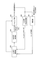
このため、非ライセンスバンドにおいて運用されるWi-Fiシステムでは、LBT(Listen Before Talk)メカニズムに基づくキャリア検知多重アクセス/衝突回避(CSMA/CA:Carrier Sense Multiple Access/Collision Avoidance)が採用されている。具体的には、各送信ポイント(TP:Transmission Point)、アクセスポイント(AP:Access Point)、Wi-Fi端末(STA:Station)等が、送信を行う前にリスニング(CCA:Clear Channel Assessment)を実行し、所定レベルを超える信号が存在しない場合にのみ送信を行う方法等が用いられている。所定レベルを超える信号が存在する場合には、ランダムに与えられる待ち時間(バックオフ時間)を設け、その後再びリスニングを行う(図2参照)。
For this reason, Wi-Fi systems operated in non-licensed bands employ Carrier Sense Multiple Access / Collision Avoidance (CSMA / CA) based on the LBT (Listen Before Talk) mechanism. . Specifically, each transmission point (TP: Transmission Point), access point (AP: Access Point), Wi-Fi terminal (STA: Station), etc. listens (CCA: Clear Channel Assessment) before transmitting. For example, a method is used in which transmission is performed only when there is no signal exceeding a predetermined level. When a signal exceeding a predetermined level exists, a waiting time (back-off time) given at random is provided, and then listening is performed again (see FIG. 2).
そこで、非ライセンスバンドで運用するLTE/LTE-Aシステム(例えば、LAA)においても、リスニング結果に基づいた送信制御を行うことが検討されている。なお、本明細書において、リスニングとは、無線基地局及び/又はユーザ端末が信号の送信を行う前に、他の送信ポイントから所定レベル(例えば、所定電力)を超える信号が送信されているか否かを検出/測定する動作を指す。また、無線基地局及び/又はユーザ端末が行うリスニングは、LBT(Listen Before Talk)、CCA(Clear Channel Assessment)等とも呼ばれることがある。以下の説明では、ユーザ端末が行うリスニングを単にLBTとも記載する。
Therefore, it has been studied to perform transmission control based on the listening result even in an LTE / LTE-A system (for example, LAA) operated in a non-licensed band. In this specification, listening means whether a signal exceeding a predetermined level (for example, predetermined power) is transmitted from another transmission point before the radio base station and / or the user terminal transmits the signal. This refers to the operation of detecting / measuring. The listening performed by the radio base station and / or the user terminal may be referred to as LBT (Listen Before Talk), CCA (Clear Channel Assessment), or the like. In the following description, the listening performed by the user terminal is also simply referred to as LBT.
例えば、無線基地局及び/又はユーザ端末は、非ライセンスバンドセルにおいて信号を送信する前にリスニング(LBT)を行い、他システム(たとえば、Wi-Fi)や他オペレータが通信を行っているか確認する。リスニングの結果、他システムや別のLAAの送信ポイントからの受信信号強度が所定値以下である場合、無線基地局及び/又はユーザ端末は、チャネルがアイドル状態(LBT_idle)であるとみなし、信号の送信を行う。一方で、リスニングの結果、他システムや他のLAAの送信ポイントからの受信信号強度が所定値より大きい場合、チャネルがビジー状態(LBT_busy)であるとみなし、信号の送信を制限する。なお、信号送信の制限としては、DFS(Dynamic Frequency Selection)により別キャリアに遷移する、送信電力制御(TPC)を行う、又は、信号送信を待機(停止)することができる。以下の説明では、信号送信の制限として信号送信を待機(停止)する場合を例に挙げて説明する。
For example, a radio base station and / or a user terminal performs listening (LBT) before transmitting a signal in an unlicensed band cell, and checks whether another system (for example, Wi-Fi) or another operator is communicating. . As a result of listening, when the received signal strength from the transmission point of another system or another LAA is below a predetermined value, the radio base station and / or the user terminal considers that the channel is in an idle state (LBT_idle) Send. On the other hand, if the received signal strength from the transmission point of another system or another LAA is larger than a predetermined value as a result of listening, the channel is regarded as being in a busy state (LBT_busy) and signal transmission is restricted. In addition, as a restriction | limiting of signal transmission, it can change to another carrier by DFS (Dynamic Frequency Selection), can perform transmission power control (TPC), or can wait (stop) signal transmission. In the following description, a case of waiting (stopping) signal transmission as an example of signal transmission restriction will be described as an example.
このように、非ライセンスバンドで運用するLTE/LTE-Aシステムの通信においてLBTを適用することにより、他のシステムとの干渉等を低減することが可能となる。
Thus, by applying LBT in the communication of the LTE / LTE-A system operating in the non-licensed band, it becomes possible to reduce interference with other systems.
しかし、LTE/LTE-Aにおいてユーザ端末がLBT結果に基づいてUL送信を制御する場合、LBT動作(例えば、LBTタイミング等)をどのように制御するかが問題となる。
However, when the user terminal controls the UL transmission based on the LBT result in LTE / LTE-A, how to control the LBT operation (for example, LBT timing) becomes a problem.
LTE/LTE-Aシステム(例えば、ライセンスバンド)において、ユーザ端末は制御信号(例えば、PUCCH)とデータ信号(例えば、PUSCH)に加えて上り参照信号を送信する。上り参照信号として、ユーザ端末は、チャネル品質測定用の参照信号(SRS:Sounding Reference Signal)を送信することができる。無線基地局は、ユーザ端末から送信されるSRSに基づいてULの品質を測定し、ULの品質に基づいてULスケジューリング等の制御を行うことができる。
In an LTE / LTE-A system (for example, license band), a user terminal transmits an uplink reference signal in addition to a control signal (for example, PUCCH) and a data signal (for example, PUSCH). As an uplink reference signal, the user terminal can transmit a channel quality measurement reference signal (SRS: Sounding Reference Signal). The radio base station can measure the UL quality based on the SRS transmitted from the user terminal, and can perform control such as UL scheduling based on the UL quality.
ユーザ端末が送信するSRSとして、周期的に送信する周期的SRS(Periodic SRS)と、無線基地局からのトリガにより非周期的に送信する非周期的SRS(Aperiodic SRS)がサポートされている。ユーザ端末は、上位レイヤで設定された所定周期に基づいて周期的SRS(P-SRS)の送信を制御する。また、ユーザ端末は、上位レイヤで設定されたSRSパラメータ(例えば、周期等)と、下り制御信号(DCI)で指示されるトリガに基づいて非周期的SRS(A-SRS)の送信を制御する。
As the SRS transmitted by the user terminal, a periodic SRS (Periodic SRS) to be transmitted periodically and an aperiodic SRS (Aperiodic SRS) to be transmitted aperiodically by a trigger from a radio base station are supported. The user terminal controls transmission of periodic SRS (P-SRS) based on a predetermined period set in an upper layer. Further, the user terminal controls transmission of the aperiodic SRS (A-SRS) based on an SRS parameter (for example, period) set in the higher layer and a trigger indicated by a downlink control signal (DCI). .
リスニング結果に基づいてPUSCH、PUCCH及びSRS等のUL信号の送信を制御する場合、どのようにリスニング動作を制御するかが問題となる。例えば、PUSCH及び/又はPUCCHの送信前に加えて、各SRSの送信前にリスニングを実施するように制御することが考えられる。しかし、周期的SRS(P-SRS)が短周期(例えば、2ms)に設定される場合、ユーザ端末はPUSCHやPUCCHの送信を行わなくても短周期でリスニングとSRS送信を繰り返すこととなる。その結果、ユーザ端末における消費電力が増大するおそれがある。
When controlling the transmission of UL signals such as PUSCH, PUCCH, and SRS based on the listening result, how to control the listening operation becomes a problem. For example, it is conceivable to perform control so that listening is performed before transmission of each SRS in addition to transmission of PUSCH and / or PUCCH. However, when the periodic SRS (P-SRS) is set to a short cycle (for example, 2 ms), the user terminal repeats listening and SRS transmission in a short cycle without performing PUSCH or PUCCH transmission. As a result, power consumption in the user terminal may increase.
一方、無線基地局側でULにおけるLBT結果を把握することが出来ない場合、無線基地局は、設定したSRSがユーザ端末から正しく送信されているか判断することが困難となる。特に、LBT結果がビジー状態(LBT_busy)となる確率は通信環境によって異なるため、無線基地局側でどの程度SRSが正しく送信されるか把握することが困難となる。このようにSRSが所定タイミングで正しく送信されない場合、無線基地局はUL品質測定を適切に行うことが出来なくなるおそれがある。
On the other hand, when the wireless base station cannot grasp the LBT result in the UL, it is difficult for the wireless base station to determine whether the set SRS is correctly transmitted from the user terminal. In particular, since the probability that the LBT result is in a busy state (LBT_busy) varies depending on the communication environment, it is difficult to grasp how much SRS is correctly transmitted on the radio base station side. As described above, when the SRS is not correctly transmitted at a predetermined timing, the radio base station may not be able to appropriately perform UL quality measurement.
そこで、本発明者等は、ユーザ端末が他の送信ポイントから送信される信号の検出/測定結果に基づいてUL送信を制御する場合に、リスニング動作(例えば、タイミング)及び/又はUL参照信号の送信動作を制御することを着想した。例えば、ユーザ端末は、上りデータ(PUSCH)及び/又は上り制御信号(PUCCH)の送信有無に応じて、上り参照信号(例えば、SRS)のリスニング動作及び/又は送信動作を制御する。
Therefore, the present inventors, etc., when the user terminal controls UL transmission based on detection / measurement results of signals transmitted from other transmission points, the listening operation (for example, timing) and / or UL reference signal Inspired to control the transmission operation. For example, the user terminal controls a listening operation and / or a transmission operation of an uplink reference signal (for example, SRS) according to whether or not uplink data (PUSCH) and / or uplink control signal (PUCCH) is transmitted.
本実施の形態の一態様として、PUSCH及び/又はPUCCH(以下、「PUSCH/PUCCH」とも記す)を送信する前、又はSRSを送信する前にLBTタイミングを設ける。また、SRSを送信するサブフレームにおいてPUSCH/PUCCHが送信されない場合、SRS送信用にLBTを行う。さらに、SRSを送信するサブフレームにおいてPUSCH/PUCCHが送信される場合、PUSCH/PUCCH送信用のLBTとSRS送信用のLBTを共有する。なお、PUSCH/PUCCH送信用のLBTタイミングとSRS用のLBTタイミングは、各サブフレームの同じ期間に設定してもよいし、異なる期間に設定してもよい。
As an aspect of the present embodiment, LBT timing is provided before transmitting PUSCH and / or PUCCH (hereinafter also referred to as “PUSCH / PUCCH”) or before transmitting SRS. Moreover, when PUSCH / PUCCH is not transmitted in the sub-frame which transmits SRS, LBT is performed for SRS transmission. Furthermore, when PUSCH / PUCCH is transmitted in a subframe in which SRS is transmitted, an LBT for PUSCH / PUCCH transmission and an LBT for SRS transmission are shared. Note that the PUSCH / PUCCH transmission LBT timing and the SRS LBT timing may be set in the same period of each subframe or in different periods.
他の態様として、ユーザ端末は、SRSを送信するサブフレームにおいてPUSCH/PUCCHが送信される場合にSRSの送信を行い、PUSCH及びPUCCHが送信されないサブフレームにおいてSRSの送信を制限することができる。
As another aspect, the user terminal can transmit SRS when PUSCH / PUCCH is transmitted in a subframe in which SRS is transmitted, and can limit SRS transmission in a subframe in which PUSCH and PUCCH are not transmitted.
また、SRSを送信するサブフレーム(n)においてPUSCH及びPUCCHが送信されない場合であっても、次サブフレーム(n+1)においてPUSCH/PUCCHが送信される場合はSRSを送信するように制御することができる。この場合、次サブフレーム(n+1)で送信されるPUSCH/PUCCHの送信前に行うLBTと、サブフレーム(n)の最終シンボルに多重されるSRSのLBTを共有して行うことができる。
Further, even when PUSCH and PUCCH are not transmitted in subframe (n) for transmitting SRS, control is performed so as to transmit SRS when PUSCH / PUCCH is transmitted in the next subframe (n + 1). it can. In this case, the LBT performed before transmission of the PUSCH / PUCCH transmitted in the next subframe (n + 1) and the SBT LBT multiplexed in the last symbol of the subframe (n) can be shared.
以下に本実施の形態について図面を参照して詳細に説明する。なお、以下の説明では上り参照信号としてSRSを例に挙げて説明するが、本実施の形態はこれに限られない。また、以下の説明では、ライセンスバンドはLBTが設定されないキャリア、非ライセンスバンドはLBTが設定されるキャリアとして説明するが、本実施の形態はこれに限られない。例えば、ライセンスバンドをLBTが設定されるキャリアとしてもよい。つまり、本実施の形態は、LBTが設定されるキャリアであれば、ライセンスバンド又は非ライセンスバンドに関わらず適用することができる。
Hereinafter, the present embodiment will be described in detail with reference to the drawings. In the following description, SRS is exemplified as an uplink reference signal, but the present embodiment is not limited to this. In the following description, the license band is described as a carrier in which LBT is not set, and the non-licensed band is described as a carrier in which LBT is set. However, the present embodiment is not limited to this. For example, the license band may be a carrier in which LBT is set. That is, the present embodiment can be applied to any carrier for which LBT is set regardless of the license band or the non-license band.
(第1の態様)
第1の態様では、ULにおけるリスニング(LBT)タイミングをPUSCH/PUCCH送信と、SRS送信を考慮して制御する場合について説明する。
(First aspect)
A 1st aspect demonstrates the case where the listening (LBT) timing in UL is controlled in consideration of PUSCH / PUCCH transmission and SRS transmission.
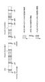
図3に第1の態様におけるLBTのタイミングの一例を示す。図3では、PUSCH/PUCCH送信の直前、又はSRS送信の直前でLBTを行う場合を示している。なお、ここでPUSCH/PUCCH送信の直前とは、PUSCH/PUCCHが割当てられる領域より前の領域(シンボル)を指す。例えば、PUSCH/PUCCHが割当てられるシンボルの一つ前のシンボルを少なくとも含む領域とすることができる。PUSCH/PUCCHが割当てられる領域より前の領域(シンボル)はPUSCH/PUCCHが割当てられるサブフレームと同じであってもよいし、一つ前のサブフレームであってもよい。SRS送信の直前も同様である。
FIG. 3 shows an example of LBT timing in the first mode. FIG. 3 shows a case where LBT is performed immediately before PUSCH / PUCCH transmission or immediately before SRS transmission. Here, “immediately before PUSCH / PUCCH transmission” refers to a region (symbol) before a region to which PUSCH / PUCCH is allocated. For example, it may be a region including at least a symbol preceding the symbol to which PUSCH / PUCCH is assigned. The region (symbol) before the region to which PUSCH / PUCCH is allocated may be the same as the subframe to which PUSCH / PUCCH is allocated, or may be the previous subframe. The same applies to immediately before SRS transmission.
例えば、PUSCH/PUCCHを送信しSRSは送信しない場合、当該PUSCH/PUCCH送信を行う前(第1のタイミング)にLBTを実施する。この場合、PUSCH/PUCCHを送信するサブフレームの先頭領域(例えば、先頭シンボルを少なくとも含む領域)を用いてLBTを実施することができる。あるいは、PUSCH/PUCCHを送信するサブフレームより一つ前のサブフレームの末端領域(例えば、最終シンボルを少なくとも含む領域)を用いてLBTを実施してもよい。リスニングの結果、他の送信ポイントからの信号が検出されない場合(例えば、受信電力が所定値以下の場合)、ユーザ端末はPUSCH/PUCCHを送信する。
For example, when PUSCH / PUCCH is transmitted and SRS is not transmitted, LBT is performed before performing the PUSCH / PUCCH transmission (first timing). In this case, LBT can be implemented using the head region (for example, the region including at least the head symbol) of the subframe in which PUSCH / PUCCH is transmitted. Or you may implement LBT using the terminal area | region (for example, area | region including the last symbol at least) of the sub-frame immediately before the sub-frame which transmits PUSCH / PUCCH. As a result of listening, when a signal from another transmission point is not detected (for example, when reception power is a predetermined value or less), the user terminal transmits PUSCH / PUCCH.
また、PUSCH及びPUCCHの送信を行わず、SRSのみを送信するサブフレームでは、SRSの送信を行う前(第2のタイミング)にLBTを実施する。この場合、SRSが割当てられるシンボルの直前シンボルを含む領域を用いてLBTを実施することができる。リスニングの結果、他の送信ポイントからの信号が検出されない場合、ユーザ端末はSRSを送信する。
Also, in a subframe in which only the SRS is transmitted without transmitting the PUSCH and the PUCCH, the LBT is performed before the SRS is transmitted (second timing). In this case, LBT can be performed using a region including a symbol immediately before a symbol to which SRS is assigned. If a signal from another transmission point is not detected as a result of listening, the user terminal transmits an SRS.
また、PUSCH/PUCCHと、SRSとを送信するサブフレームでは、当該PUSCH/PUCCHの送信を行う前(第1のタイミング)にLBTを実施する。この場合、LBTのタイミングは、PUSCH/PUCCHを送信しSRSは送信しない場合と同一とすることができる。つまり、PUSCH/PUCCH送信用のLBTとSRS送信用のLBTを共有して(1回で)行うことが出来るため、LBT回数を低減することができる。
Also, in a subframe in which PUSCH / PUCCH and SRS are transmitted, LBT is performed before transmission of the PUSCH / PUCCH (first timing). In this case, the timing of the LBT can be the same as when PUSCH / PUCCH is transmitted and SRS is not transmitted. That is, since the PUSCH / PUCCH transmission LBT and the SRS transmission LBT can be shared (in one time), the number of LBT can be reduced.
このように、SRSが送信されるサブフレームにおいてPUSCH/PUCCHの送信を考慮してLBT動作(LBTタイミング等)を制御することにより、ULにおけるLBT回数を抑制することができる。これによりユーザ端末が受信(LBT)と送信を繰り返す回数または頻度を減らし、ユーザ端末のバッテリー消費や、LBT_busyを検出して通信に遅延が生じる確率を低減することができる。
Thus, by controlling the LBT operation (such as LBT timing) in consideration of PUSCH / PUCCH transmission in the subframe in which the SRS is transmitted, the number of LBTs in the UL can be suppressed. Thereby, the frequency | count or frequency which a user terminal repeats reception (LBT) and transmission can be reduced, and the probability that the delay of communication will occur by detecting the battery consumption of the user terminal and LBT_busy can be reduced.
なお、複数のサブフレームにわたってUL信号を連続して送信する場合、当該連続送信の前(例えば、連続送信を行う直前)にLBTを1回行う構成としてもよい。例えば、PUSCH/PUCCHを送信するサブフレームより一つ前のサブフレームにおいて、SRSのみ送信する場合、当該SRSの送信を行う前(第2のタイミング)にLBTを実施することができる。この場合もPUSCH/PUCCH送信用のLBTとSRS送信用のLBTを共有して(1回で)行うことが出来るため、LBT回数を低減することができる。
In addition, when transmitting UL signal continuously over several sub-frames, it is good also as a structure which performs LBT once before the said continuous transmission (for example, just before performing continuous transmission). For example, when only SRS is transmitted in a subframe immediately before a subframe in which PUSCH / PUCCH is transmitted, LBT can be performed before transmission of the SRS (second timing). Also in this case, since the PUSCH / PUCCH transmission LBT and the SRS transmission LBT can be shared (in one time), the number of LBT can be reduced.
(第2の態様)
第1の態様では、PUSCH及びPUCCHを送信せずにSRSを送信するサブフレームにおいてSRSの送信前(第2のタイミング)でLBTを行う場合を示した。第2の態様では、LBTを行うサブフレームにおいて、PUSCH/PUCCH送信用のLBTタイミング(第1のタイミング)と、SRS送信用のLBTタイミング(第2のタイミング)とを同一に設定する場合について説明する。
(Second aspect)
In the 1st mode, the case where LBT was performed before the transmission of SRS (2nd timing) in the subframe which transmits SRS, without transmitting PUSCH and PUCCH was shown. In the second mode, the case where the LBT timing for PUSCH / PUCCH transmission (first timing) and the LBT timing for SRS transmission (second timing) are set to be the same in a subframe in which LBT is performed is described. To do.
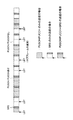
図4に第2の態様におけるLBTのタイミングの一例を示す。図4では、PUSCH/PUCCHを送信しSRSを送信しない場合、SRSを送信しPUSCH及びPUCCHを送信しない場合、及び、PUSCH/PUCCHとSRSを送信する場合において、同じタイミングでLBTを実施する場合を示している。同じタイミングとは、同一の周期・時間オフセットで特定される領域を用いてLBTを行うことを指す。
FIG. 4 shows an example of LBT timing in the second mode. In FIG. 4, when PUSCH / PUCCH is transmitted and SRS is not transmitted, when SRS is transmitted and PUSCH and PUCCH are not transmitted, and when PUSCH / PUCCH and SRS are transmitted, LBT is performed at the same timing. Show. The same timing indicates that LBT is performed using regions specified by the same period / time offset.
例えば、SRSのみを送信する場合も、PUSCH/PUCCHを送信する場合に実施するLBTタイミング(例えば、割当てられるサブフレームの直前)と同一とする。この場合、UL信号の送信種別に関わらず、サブフレームにおけるLBTタイミングを一つに設定することができる。これにより、ユーザ端末がLBTを行う場合に、当該LBT処理を簡略化することが可能となる。なお、図4では、あるサブフレームにおいてPUSCH及びPUCCHを送信せずにSRSのみ送信する場合には、LBTからSRS送信までの間にUL送信を行わない期間が生じる。
For example, even when only SRS is transmitted, it is the same as the LBT timing (for example, immediately before the assigned subframe) that is performed when PUSCH / PUCCH is transmitted. In this case, the LBT timing in the subframe can be set to one regardless of the UL signal transmission type. Thereby, when a user terminal performs LBT, it becomes possible to simplify the said LBT process. In FIG. 4, when only SRS is transmitted without transmitting PUSCH and PUCCH in a certain subframe, there is a period during which UL transmission is not performed between LBT and SRS transmission.
また、複数のサブフレームに渡ってUL信号を連続して送信する場合、当該連続送信の前(例えば、連続送信を行う直前サブフレームの所定領域)に複数サブフレームのUL信号送信用のLBTを共有して行うことができる。
In addition, when continuously transmitting UL signals over a plurality of subframes, an LBT for transmitting UL signals of a plurality of subframes is transmitted before the continuous transmission (for example, a predetermined area of a subframe immediately before performing continuous transmission). Can be shared.
このように、SRSが送信されるサブフレームにおいてPUSCH/PUCCHの送信を考慮してLBT動作を制御すると共に、サブフレームにおけるLBTタイミングを同一とすることにより、LBT回数を抑制すると共にLBT動作を簡略化することができる。
As described above, the LBT operation is controlled in consideration of the transmission of PUSCH / PUCCH in the subframe in which the SRS is transmitted, and the LBT timing in the subframe is made the same, thereby suppressing the number of LBT and simplifying the LBT operation. Can be
(第3の態様)
第3の態様では、リスニング結果に基づいてUL送信を制御する場合に、UL参照信号(例えば、SRS)の送信を所定サブフレームに制限する場合について説明する。
(Third aspect)
In the third aspect, a case where transmission of a UL reference signal (for example, SRS) is limited to a predetermined subframe when UL transmission is controlled based on a listening result will be described.
第3の態様におけるUL参照信号の送信制御方法の一例を図5A示す。ユーザ端末は、上り参照信号(例えば、SRS)の送信を、PUSCH/PUCCHが送信されるサブフレームと同一サブフレームに制限する。つまり、ユーザ端末は、PUSCH/PUCCHが送信されるサブフレームにおいてのみSRSの送信を行う。
FIG. 5A shows an example of a UL reference signal transmission control method in the third mode. The user terminal restricts transmission of an uplink reference signal (for example, SRS) to the same subframe as the subframe in which PUSCH / PUCCH is transmitted. That is, a user terminal transmits SRS only in a subframe in which PUSCH / PUCCH is transmitted.
この場合、ユーザ端末は、PUSCH/PUCCHが送信される前にLBTを行い、当該LBTの結果に基づいてPUSCH、PUCCH及びSRSの送信を制御する。つまり、同一サブフレームで送信するPUSCH、PUCCH及びSRS用のLBTを共用して(1回で)行うことができる。また、SRSの送信をPUSCH/PUCCH送信に応じて制御することにより、SRS送信用のみのLBTを省略することができる。
In this case, the user terminal performs LBT before PUSCH / PUCCH is transmitted, and controls transmission of PUSCH, PUCCH, and SRS based on the result of the LBT. That is, PUSCH, PUCCH, and LBT for SRS transmitted in the same subframe can be shared (performed). Moreover, LBT only for SRS transmission is omissible by controlling transmission of SRS according to PUSCH / PUCCH transmission.
なお、LBTのタイミングは、PUSCH/PUCCHの送信に基づいて行うことができる。具体的には、上記第1の態様におけるPUSCH/PUCCH送信用のLBTタイミング(第1のタイミング)、上記第2の態様におけるLBTタイミングを適用することができる。
Note that the LBT timing can be performed based on PUSCH / PUCCH transmission. Specifically, the PUBT / PUCCH transmission LBT timing in the first aspect (first timing) and the LBT timing in the second aspect can be applied.
また、無線基地局は、ULにおけるSRS送信を既存のLTE/LTE-A(例えば、ライセンスバンド)と同様に設定・トリガ(Configure/Trigger)することができる。但し、ユーザ端末は、SRSが設定されている場合であっても、所定条件に基づいてSRSの送信又は非送信(Drop)を制御する。例えば、ULにおけるリスニング結果がLBT_idle、UL送信を行うサブフレームにPUSCH/PUCCH送信が存在し、且つ当該サブフレームでSRSの送信がある(トリガされている)場合に、ユーザ端末はSRSの送信を行うことができる。
Also, the radio base station can configure / trigger SRS transmission in the UL in the same manner as existing LTE / LTE-A (for example, license band). However, the user terminal controls transmission or non-transmission (Drop) of SRS based on a predetermined condition even when SRS is set. For example, when the listening result in UL is LBT_idle, PUSCH / PUCCH transmission exists in a subframe in which UL transmission is performed, and when there is SRS transmission (triggered) in the subframe, the user terminal transmits SRS transmission. It can be carried out.
また、複数のサブフレームに渡ってPUSCH/PUCCHを連続して送信する場合、当該連続送信の前(例えば、連続送信を行う直前)にLBTを1回行う構成としてもよい。なお、図5Aでは、各UL送信(連続する場合には先頭のUL送信)の前にLBTを行う場合を示しているが、本実施の形態はこれに限られない。ULにおけるLBTの結果がLBT_idleである場合、所定期間(バースト期間とも呼ぶ)に渡ってUL信号の送信を許容してもよい。この場合、バースト期間であればPUSCH及び/又はPUCCHが送信されないサブフレームにおいてSRSのみ送信する構成としてもよい。
Further, when PUSCH / PUCCH is continuously transmitted over a plurality of subframes, LBT may be performed once before the continuous transmission (for example, immediately before continuous transmission). Although FIG. 5A shows a case where LBT is performed before each UL transmission (first UL transmission in the case of continuous transmission), the present embodiment is not limited to this. When the result of LBT in the UL is LBT_idle, transmission of the UL signal may be permitted over a predetermined period (also referred to as a burst period). In this case, only the SRS may be transmitted in a subframe in which PUSCH and / or PUCCH is not transmitted during the burst period.
このように、PUSCH/PUCCHの送信有無に基づいてSRSの送信を限定/制限することにより、ULにおけるLBT回数を抑制すると共にLBT動作を簡略化することができる。
Thus, by limiting / restricting the transmission of SRS based on the presence / absence of PUSCH / PUCCH transmission, the number of LBT in the UL can be suppressed and the LBT operation can be simplified.
また、PUSHC/PUCCH送信とSRS送信用のLBTタイミングを同一とする場合に、PUSCH/PUCCHの送信有無に基づいてSRSの送信を限定/制限することにより、LBTからSRS送信までの空白期間が生じることを抑制できる。これにより、LBTからSRS送信までの空白期間に他の送信ポイント(例えば、Wi-Fi等)で発生した信号と衝突すること(図5B参照)を抑制することができる。
In addition, when the PBTHC / PUCCH transmission and the LBT timing for SRS transmission are made the same, by limiting / restricting SRS transmission based on the presence / absence of PUSCH / PUCCH transmission, a blank period from LBT to SRS transmission occurs. This can be suppressed. Thereby, it is possible to suppress collision (see FIG. 5B) with a signal generated at another transmission point (for example, Wi-Fi or the like) during the blank period from LBT to SRS transmission.
また、無線基地局は、PUSCH/PUCCHの検出結果に基づいて、ユーザ端末から送信されるSRSがドロップされたか、あるいは正しく送信されたかを判断することができる。また、第3の態様を適用することにより、トラフィックが多いセル程適切にSRSを送信することが可能となり、より正確なリンクアダプテーション(Link adaptation)を行うことができる。
Also, the radio base station can determine whether the SRS transmitted from the user terminal has been dropped or transmitted correctly based on the detection result of PUSCH / PUCCH. Also, by applying the third mode, it becomes possible to appropriately transmit SRS as the cell has more traffic, and more accurate link adaptation can be performed.
<変形例>
なお、図5Aでは、SRSの送信を同一セル・サブフレームでPUSCH/PUCCHが存在する場合に制限する例を示したが、これに限られない。例えば、PUSCH/PUCCHが送信されるサブフレーム(n)の一つ前のサブフレーム(n-1)のサブフレームでSRSが設定される場合に当該SRSを送信可能としてもよい。つまり、PUSCH/PUCCHが送信されないサブフレームであっても、次サブフレームでPUSCH/PUCCHが送信される場合には、SRSのみ送信することも可能である(図6参照)。
<Modification>
Although FIG. 5A shows an example in which the transmission of SRS is limited to the case where PUSCH / PUCCH exists in the same cell / subframe, the present invention is not limited to this. For example, when the SRS is set in the subframe (n−1) immediately before the subframe (n) in which PUSCH / PUCCH is transmitted, the SRS may be transmitted. That is, even if the PUSCH / PUCCH is not transmitted, if the PUSCH / PUCCH is transmitted in the next subframe, only the SRS can be transmitted (see FIG. 6).
例えば、ULにおけるリスニング結果がLBT_idle、LBTタイミングでSRSの送信があり(トリガされており)、且つ直後のサブフレームにPUSCH/PUCCH送信がある場合、ユーザ端末はSRSの送信を行う。この場合、ユーザ端末は、サブフレーム(n-1)で送信するSRSと、次サブフレーム(n)で送信するPUSCH/PUCCHに対してLBTを共有して(1回で)行うことができる。
For example, when the listening result in UL is LBT_idle, SRS transmission is triggered at LBT timing (triggered), and there is PUSCH / PUCCH transmission in the immediately following subframe, the user terminal transmits SRS. In this case, the user terminal can share the LBT for the SRS transmitted in the subframe (n−1) and the PUSCH / PUCCH transmitted in the next subframe (n) (in one time).
<動作手順>
第3の態様における動作手順の一例を説明する。
<Operation procedure>
An example of the operation procedure in the third aspect will be described.
無線基地局は、ULでリスニング動作を行うユーザ端末(例えば、非ライセンスバンドに接続するユーザ端末)に対して、周期的SRS及び/又は非周期的SRSを設定する。つまり、LAAシステムを利用するユーザ端末は、非ライセンスバンドにおいても既存LTE/LTE-A(例えば、ライセンスバンド)と同様に周期的SRS及び/又は非周期的SRSが設定される。なお、無線基地局は、周期的SRS及び/又は非周期的SRSの設定を非ライセンスバンドに限られず、ライセンスバンドを利用して設定してもよい。
The radio base station sets a periodic SRS and / or an aperiodic SRS for a user terminal (for example, a user terminal connected to a non-licensed band) that performs a listening operation in the UL. That is, the user terminal that uses the LAA system is set to the periodic SRS and / or the aperiodic SRS in the non-licensed band as well as the existing LTE / LTE-A (for example, license band). Note that the radio base station is not limited to setting the periodic SRS and / or the aperiodic SRS to a non-licensed band, and may use a license band.
ユーザ端末は、LBT動作が要求されるCC(又は非ライセンスバンドCC)において、LBTの結果に基づいてUL送信を制御する。具体的には、LBT結果がLBT_idleである場合に、ユーザ端末はPUSCH及び/又はPUCCHを送信する。
The user terminal controls UL transmission based on the result of the LBT in the CC (or non-licensed band CC) in which the LBT operation is required. Specifically, when the LBT result is LBT_idle, the user terminal transmits PUSCH and / or PUCCH.
また、ユーザ端末は、LBT結果がLBT_idleであった時のPUSCH及び/PUCCHの送信タイミング(例えば、送信サブフレーム)においてSRSが設定されている場合に、当該SRSの送信を行う。
Also, the user terminal transmits the SRS when the SRS is set in the PUSCH and / PUCCH transmission timing (for example, transmission subframe) when the LBT result is LBT_idle.
それ以外の場合(例えば、LBT結果がLBT_busyである場合、PUSCH及び/又はPUCCHの送信がない場合)、ユーザ端末はSRSの送信を行わない(ドロップする)ように制御する。これにより、PUSCH及び/又はPUCCH送信とSRS送信用に行うLBTを1回とすることが出来ると共に、無線基地局は、PUSCH及び/又はPUCCHの検出結果に基づいて、ユーザ端末から送信されるSRSがドロップされたか、あるいは正しく送信されたかを判断することができる。
In other cases (for example, when the LBT result is LBT_busy, when there is no PUSCH and / or PUCCH transmission), the user terminal performs control so as not to transmit (drop) the SRS. Accordingly, PUSCH and / or PUCCH transmission and LBT performed for SRS transmission can be performed once, and the radio base station can transmit SRS transmitted from the user terminal based on the detection result of PUSCH and / or PUCCH. It can be determined whether has been dropped or transmitted correctly.
なお、ユーザ端末は、LBT結果がLBT_idleであった時のPUSCH及び/PUCCHの送信タイミング(例えば、送信サブフレーム)の直前のサブフレームにおいてSRSが設定されている場合に、当該SRSの送信を行ってもよい。
Note that the user terminal transmits the SRS when the SRS is set in the subframe immediately before the PUSCH and / PUCCH transmission timing (for example, the transmission subframe) when the LBT result is LBT_idle. May be.
(第4の態様)
第4の態様では、SRSをLBTが不要(LBT-exempt)となる長周期で送信する場合について説明する。
(Fourth aspect)
In the fourth aspect, a case will be described in which SRS is transmitted in a long cycle in which LBT is unnecessary (LBT-exempt).
LBTが要求されるシステムでは、送信周期が所定以下の信号に対してLBT結果に基づく送信制御が要求される。その一方で、送信周期が長周期(例えば、20ms以上)の信号に対してはLBTを不要(LBT-exempt)として制御することも想定される。
In a system where LBT is required, transmission control based on the LBT result is required for a signal whose transmission cycle is a predetermined value or less. On the other hand, it is assumed that the LBT is controlled as unnecessary (LBT-exempt) for a signal having a long transmission period (for example, 20 ms or more).
したがって、第4の態様では、SRSの送信をLBTが不要となる長周期(例えば、20ms周期)で制御する(図7参照)。これにより、SRS送信のDuty cycleを下げて、SRSをLBT非適用送信とすることができる。この場合、無線基地局及び/又はユーザ端末は、LBT動作が要求されるCC(又は非ライセンスバンドCC)において、SRSの送信を長周期(例えば、20ms以上の周期)に設定して制御することができる。
Therefore, in the fourth aspect, SRS transmission is controlled in a long cycle (for example, 20 ms cycle) in which LBT is unnecessary (see FIG. 7). Thereby, the duty cycle of SRS transmission can be lowered, and SRS can be set to LBT non-application transmission. In this case, the radio base station and / or the user terminal controls the transmission of SRS in a long cycle (for example, a cycle of 20 ms or more) in a CC (or non-licensed band CC) in which an LBT operation is required Can do.
なお、第4の態様を他の態様(第1~第3の態様)と組み合わせて適用してもよい。この場合、LBT非適用となる長周期のSRSと、LBTを適用する周期的SRS及び/又は非周期的SRSとを組み合わせて利用することができる。
It should be noted that the fourth aspect may be applied in combination with other aspects (first to third aspects). In this case, a long-period SRS to which LBT is not applied can be used in combination with a periodic SRS and / or an aperiodic SRS to which LBT is applied.
(無線通信システムの構成)
以下、本実施の形態に係る無線通信システムの構成について説明する。この無線通信システムでは、上記第1の態様~第4の態様に係る無線通信方法が適用される。なお、上記第1の態様~第4の態様に係る構成は、それぞれ単独で適用してもよいし、組み合わせて適用してもよい。
(Configuration of wireless communication system)
Hereinafter, the configuration of the wireless communication system according to the present embodiment will be described. In this radio communication system, the radio communication methods according to the first to fourth aspects are applied. Note that the configurations according to the first to fourth aspects may be applied alone or in combination.
図8は、本実施の形態に係る無線通信システムの概略構成図である。なお、図8に示す無線通信システムは、例えば、LTEシステム或いは、SUPER 3Gが包含されるシステムである。この無線通信システムでは、LTEシステムのシステム帯域幅を1単位とする複数の基本周波数ブロック(コンポーネントキャリア)を一体としたキャリアアグリゲーション(CA)及び/又はデュアルコネクティビティ(DC)を適用することができる。また、図8に示す無線通信システムは、ライセンスバンドと非ライセンスバンド(LTE-U基地局)を有している。なお、この無線通信システムは、IMT-Advancedと呼ばれても良いし、4G、5G、FRA(Future Radio Access)と呼ばれても良い。
FIG. 8 is a schematic configuration diagram of the radio communication system according to the present embodiment. Note that the radio communication system shown in FIG. 8 is a system including, for example, an LTE system or SUPER 3G. In this wireless communication system, carrier aggregation (CA) and / or dual connectivity (DC) in which a plurality of basic frequency blocks (component carriers) having the system bandwidth of the LTE system as one unit can be applied. 8 has a license band and a non-license band (LTE-U base station). This wireless communication system may be referred to as IMT-Advanced, or may be referred to as 4G, 5G, FRA (Future Radio Access).
図8に示す無線通信システム1は、マクロセルC1を形成する無線基地局11と、マクロセルC1内に配置され、マクロセルC1よりも狭いスモールセルC2を形成する無線基地局12a~12cとを備えている。また、マクロセルC1及び各スモールセルC2には、ユーザ端末20が配置されている。例えば、マクロセルC1をライセンスバンドで利用し、スモールセルC2の少なくとも一つを非ライセンスバンド(LTE-U)で利用する形態が考えられる。また、マクロセルに加えてスモールセルC2の一部をライセンスバンドで利用し、他のスモールセルC2を非ライセンスバンドで利用する形態も考えられる。
The radio communication system 1 shown in FIG. 8 includes a radio base station 11 that forms a macro cell C1, and radio base stations 12a to 12c that are arranged in the macro cell C1 and form a small cell C2 that is narrower than the macro cell C1. . Moreover, the user terminal 20 is arrange | positioned at the macrocell C1 and each small cell C2. For example, a mode in which the macro cell C1 is used in a license band and at least one of the small cells C2 is used in an unlicensed band (LTE-U) is conceivable. In addition to the macro cell, a mode in which a part of the small cell C2 is used in the license band and another small cell C2 is used in the non-licensed band is also conceivable.
ユーザ端末20は、無線基地局11及び無線基地局12の双方に接続することができる。ユーザ端末20は、異なる周波数を用いるマクロセルC1とスモールセルC2を、CA又はDCにより同時に使用することができる。この場合、ライセンスバンドを利用する無線基地局11からユーザ端末20に対して、非ライセンスバンドを利用する無線基地局12に関する情報(アシスト情報)を送信することができる。また、ライセンスバンドと非ライセンスバンドでCAを行う場合、一つの無線基地局(例えば、無線基地局11)がライセンスバンドセル及び非ライセンスバンドセルのスケジューリングを制御する構成とすることも可能である。
The user terminal 20 can be connected to both the radio base station 11 and the radio base station 12. The user terminal 20 can simultaneously use the macro cell C1 and the small cell C2 that use different frequencies by CA or DC. In this case, information (assist information) related to the radio base station 12 using the non-licensed band can be transmitted from the radio base station 11 using the license band to the user terminal 20. Further, when CA is performed in the license band and the non-license band, a configuration in which one radio base station (for example, the radio base station 11) controls the scheduling of the license band cell and the non-license band cell may be adopted.
ユーザ端末20と無線基地局11との間は、相対的に低い周波数帯域(例えば、2GHz)で帯域幅が狭いキャリア(既存キャリア、Legacy carrier等と呼ばれる)を用いて通信を行うことができる。一方、ユーザ端末20と無線基地局12との間は、相対的に高い周波数帯域(例えば、3.5GHz、5GHz等)で帯域幅が広いキャリアが用いられてもよいし、無線基地局11との間と同じキャリアが用いられてもよい。無線基地局11と無線基地局12(又は、無線基地局12間)間は、有線接続(Optical fiber、X2インタフェース等)又は無線接続した構成とすることができる。
Communication between the user terminal 20 and the radio base station 11 can be performed using a carrier having a relatively low frequency band (for example, 2 GHz) and a narrow bandwidth (referred to as an existing carrier or a legacy carrier). On the other hand, a carrier having a relatively high frequency band (for example, 3.5 GHz, 5 GHz, etc.) and a wide bandwidth may be used between the user terminal 20 and the radio base station 12. The same carrier may be used. The wireless base station 11 and the wireless base station 12 (or between the wireless base stations 12) can be configured to have a wired connection (Optical fiber, X2 interface, etc.) or a wireless connection.
無線基地局11及び各無線基地局12は、それぞれ上位局装置30に接続され、上位局装置30を介してコアネットワーク40に接続される。なお、上位局装置30には、例えば、アクセスゲートウェイ装置、無線ネットワークコントローラ(RNC)、モビリティマネジメントエンティティ(MME)等が含まれるが、これに限定されるものではない。また、各無線基地局12は、無線基地局11を介して上位局装置30に接続されてもよい。
The radio base station 11 and each radio base station 12 are connected to the higher station apparatus 30 and connected to the core network 40 via the higher station apparatus 30. The upper station device 30 includes, for example, an access gateway device, a radio network controller (RNC), a mobility management entity (MME), and the like, but is not limited thereto. Each radio base station 12 may be connected to the higher station apparatus 30 via the radio base station 11.
なお、無線基地局11は、相対的に広いカバレッジを有する無線基地局であり、eNodeB、マクロ基地局、送受信ポイントなどと呼ばれてもよい。また、無線基地局12は、局所的なカバレッジを有する無線基地局であり、スモール基地局、ピコ基地局、フェムト基地局、Home eNodeB、RRH(Remote Radio Head)、マイクロ基地局、送受信ポイントなどと呼ばれてもよい。以下、無線基地局11及び12を区別しない場合は、無線基地局10と総称する。各ユーザ端末20は、LTE、LTE-Aなどの各種通信方式に対応した端末であり、移動通信端末だけでなく固定通信端末を含んでよい。
Note that the radio base station 11 is a radio base station having a relatively wide coverage, and may be referred to as an eNodeB, a macro base station, a transmission / reception point, or the like. The radio base station 12 is a radio base station having local coverage, such as a small base station, a pico base station, a femto base station, a Home eNodeB, an RRH (Remote Radio Head), a micro base station, and a transmission / reception point. May be called. Hereinafter, when the radio base stations 11 and 12 are not distinguished, they are collectively referred to as a radio base station 10. Each user terminal 20 is a terminal that supports various communication schemes such as LTE and LTE-A, and may include not only a mobile communication terminal but also a fixed communication terminal.
無線通信システムにおいては、無線アクセス方式として、下りリンクについてはOFDMA(直交周波数分割多元接続)が適用され、上りリンクについてはSC-FDMA(シングルキャリア-周波数分割多元接続)が適用される。OFDMAは、周波数帯域を複数の狭い周波数帯域(サブキャリア)に分割し、各サブキャリアにデータをマッピングして通信を行うマルチキャリア伝送方式である。SC-FDMAは、システム帯域幅を端末毎に1つ又は連続したリソースブロックからなる帯域に分割し、複数の端末が互いに異なる帯域を用いることで、端末間の干渉を低減するシングルキャリア伝送方式である。
In a wireless communication system, OFDMA (Orthogonal Frequency Division Multiple Access) is applied to the downlink and SC-FDMA (Single Carrier Frequency Division Multiple Access) is applied to the uplink as the radio access scheme. OFDMA is a multi-carrier transmission scheme that performs communication by dividing a frequency band into a plurality of narrow frequency bands (subcarriers) and mapping data to each subcarrier. SC-FDMA is a single-carrier transmission scheme that reduces interference between terminals by dividing the system bandwidth into bands consisting of one or continuous resource blocks for each terminal and using a plurality of terminals with mutually different bands. is there.
ここで、図8に示す無線通信システムで用いられる通信チャネルについて説明する。下りリンクの通信チャネルは、各ユーザ端末20で共有されるPDSCH(Physical Downlink Shared Channel)と、下りL1/L2制御チャネル(PCFICH、PHICH、PDCCH、拡張PDCCH)とを有する。PDSCHにより、ユーザデータ及び上位制御情報が伝送される。PDCCH(Physical Downlink Control Channel)により、PDSCHおよびPUSCHのスケジューリング情報等が伝送される。PCFICH(Physical Control Format Indicator Channel)により、PDCCHに用いるOFDMシンボル数が伝送される。PHICH(Physical Hybrid-ARQ Indicator Channel)により、PUSCHに対するHARQのACK/NACKが伝送される。また、拡張PDCCH(EPDCCH)により、PDSCH及びPUSCHのスケジューリング情報等が伝送されてもよい。このEPDCCHは、PDSCH(下り共有データチャネル)と周波数分割多重される。
Here, communication channels used in the wireless communication system shown in FIG. 8 will be described. The downlink communication channel includes a PDSCH (Physical Downlink Shared Channel) shared by each user terminal 20 and a downlink L1 / L2 control channel (PCFICH, PHICH, PDCCH, extended PDCCH). User data and higher control information are transmitted by the PDSCH. PDSCH and PUSCH scheduling information and the like are transmitted by PDCCH (Physical Downlink Control Channel). The number of OFDM symbols used for PDCCH is transmitted by PCFICH (Physical Control Format Indicator Channel). The HARQ ACK / NACK for PUSCH is transmitted by PHICH (Physical Hybrid-ARQ Indicator Channel). Moreover, scheduling information of PDSCH and PUSCH may be transmitted by the extended PDCCH (EPDCCH). This EPDCCH is frequency division multiplexed with PDSCH (downlink shared data channel).
上りリンクの通信チャネルは、各ユーザ端末20で共有される上りデータチャネルとしてのPUSCH(Physical Uplink Shared Channel)と、上りリンクの制御チャネルであるPUCCH(Physical Uplink Control Channel)とを有する。このPUSCHにより、ユーザデータや上位制御情報が伝送される。また、PUCCHにより、下りリンクのチャネル状態情報(CSI)、送達確認信号(HARQ-ACK、A/N、又はACK/NACKとも呼ぶ)、スケジューリング要求(SR)等が伝送される。なお、チャネル状態情報には、無線品質情報(CQI)、プリコーディングマトリクス指標(PMI)、ランク指標(RI)等が含まれる。
The uplink communication channel includes a PUSCH (Physical Uplink Shared Channel) as an uplink data channel shared by each user terminal 20 and a PUCCH (Physical Uplink Control Channel) as an uplink control channel. User data and higher control information are transmitted by this PUSCH. Also, downlink channel state information (CSI), an acknowledgment signal (also referred to as HARQ-ACK, A / N, or ACK / NACK), a scheduling request (SR), and the like are transmitted by PUCCH. The channel state information includes radio quality information (CQI), precoding matrix index (PMI), rank index (RI), and the like.
図9は、本実施の形態に係る無線基地局10(無線基地局11及び12を含む)の全体構成図である。無線基地局10は、MIMO伝送のための複数の送受信アンテナ101と、アンプ部102と、送受信部103(送信部/受信部)と、ベースバンド信号処理部104と、呼処理部105と、伝送路インタフェース106とを備えている。
FIG. 9 is an overall configuration diagram of the radio base station 10 (including the radio base stations 11 and 12) according to the present embodiment. The radio base station 10 includes a plurality of transmission / reception antennas 101 for MIMO transmission, an amplifier unit 102, a transmission / reception unit 103 (transmission unit / reception unit), a baseband signal processing unit 104, a call processing unit 105, a transmission And a road interface 106.
下りリンクにより無線基地局10からユーザ端末20に送信されるユーザデータは、上位局装置30から伝送路インタフェース106を介してベースバンド信号処理部104に入力される。
User data transmitted from the radio base station 10 to the user terminal 20 via the downlink is input from the higher station apparatus 30 to the baseband signal processing unit 104 via the transmission path interface 106.
ベースバンド信号処理部104では、PDCPレイヤの処理、ユーザデータの分割・結合、RLC(Radio Link Control)再送制御の送信処理などのRLCレイヤの送信処理、MAC(Medium Access Control)再送制御、例えば、HARQの送信処理、スケジューリング、伝送フォーマット選択、チャネル符号化、逆高速フーリエ変換(IFFT:Inverse Fast Fourier Transform)処理、プリコーディング処理が行われて各送受信部103に転送される。また、下りリンクの制御チャネルの信号に関しても、チャネル符号化や逆高速フーリエ変換等の送信処理が行われて、各送受信部103に転送される。
The baseband signal processing unit 104 performs PDCP layer processing, user data division / combination, RLC layer transmission processing such as RLC (Radio Link Control) retransmission control transmission processing, MAC (Medium Access Control) retransmission control, for example, HARQ transmission processing, scheduling, transmission format selection, channel coding, Inverse Fast Fourier Transform (IFFT) processing, and precoding processing are performed and transferred to each transceiver 103. The downlink control channel signal is also subjected to transmission processing such as channel coding and inverse fast Fourier transform, and is transferred to each transceiver 103.
また、ベースバンド信号処理部104は、上位レイヤシグナリング(例えば、RRCシグナリング、報知情報等)により、ユーザ端末20に対して、当該セルにおける通信のための制御情報(システム情報)を通知する。当該セルにおける通信のための情報には、例えば、上りリンク又は下りリンクにおけるシステム帯域幅等が含まれる。また、ユーザ端末に対して、周期的SRSのパラメータ及び/又は非周期的SRSのパラメータに関する情報を上位レイヤシグナリングで通知してもよい。
Further, the baseband signal processing unit 104 notifies the user terminal 20 of control information (system information) for communication in the cell by higher layer signaling (for example, RRC signaling, broadcast information, etc.). The information for communication in the cell includes, for example, the system bandwidth in the uplink or the downlink. Moreover, you may notify the information regarding the parameter of periodic SRS and / or the parameter of aperiodic SRS with a higher layer signaling with respect to a user terminal.
また、無線基地局10の送受信部103からユーザ端末に対して、リスニング(LBT)に関する情報(例えば、LBTサブフレーム、LBTシンボル、LBT周期のうちの一部又は全部)を送信することができる。また、TDDにおいてLBTを適用する場合、無線基地局10は、LBTに関する情報に加えて、UL/DL構成(又はHARQ-ACKタイミングを定めるUL/DL構成(DL-reference UL/DL configuration))に関する情報をユーザ端末に送信する。例えば、無線基地局10は、これらの情報を、ライセンスバンド及び/又は非ライセンスバンドを介してユーザ端末に通知する。また、無線基地局10は、LBT結果がLBT_idleである場合に、LBT_idleを通知する参照信号(DL-BRS)を送信してもよい。
Also, information (for example, part or all of LBT subframes, LBT symbols, and LBT cycles) related to listening (LBT) can be transmitted from the transceiver unit 103 of the radio base station 10 to the user terminal. In addition, when applying LBT in TDD, the radio base station 10 relates to UL / DL configuration (or UL / DL configuration (DL-reference UL / DL configuration) that defines HARQ-ACK timing) in addition to information related to LBT. Send information to the user terminal. For example, the radio base station 10 notifies the user terminal of such information via a license band and / or a non-license band. Further, when the LBT result is LBT_idle, the radio base station 10 may transmit a reference signal (DL-BRS) for notifying LBT_idle.
各送受信部103は、ベースバンド信号処理部104からアンテナ毎にプリコーディングして出力されたベースバンド信号を無線周波数帯に変換する。アンプ部102は、周波数変換された無線周波数信号を増幅して送受信アンテナ101により送信する。なお、送受信部(送信部/受信部)103は、本発明に係る技術分野で用いられるトランスミッター/レシーバー、送受信回路(送信回路/受信回路)又は送受信装置(送信装置/受信装置)とすることができる。
Each transmission / reception unit 103 converts the baseband signal output by precoding from the baseband signal processing unit 104 for each antenna to a radio frequency band. The amplifier unit 102 amplifies the frequency-converted radio frequency signal and transmits the amplified signal using the transmission / reception antenna 101. The transmission / reception unit (transmission unit / reception unit) 103 is a transmitter / receiver, a transmission / reception circuit (transmission circuit / reception circuit) or a transmission / reception device (transmission device / reception device) used in the technical field according to the present invention. it can.
一方、上りリンクによりユーザ端末20から無線基地局10に送信されるデータについては、各送受信アンテナ101で受信された無線周波数信号がそれぞれアンプ部102で増幅され、各送受信部103で周波数変換されてベースバンド信号に変換され、ベースバンド信号処理部104に入力される。
On the other hand, for data transmitted from the user terminal 20 to the radio base station 10 via the uplink, radio frequency signals received by the respective transmission / reception antennas 101 are amplified by the amplifier units 102 and frequency-converted by the respective transmission / reception units 103. It is converted into a baseband signal and input to the baseband signal processing unit 104.
ベースバンド信号処理部104では、入力されたベースバンド信号に含まれるユーザデータに対して、FFT処理、IDFT処理、誤り訂正復号、MAC再送制御の受信処理、RLCレイヤ、PDCPレイヤの受信処理がなされ、伝送路インタフェース106を介して上位局装置30に転送される。呼処理部105は、通信チャネルの設定や解放等の呼処理や、無線基地局10の状態管理や、無線リソースの管理を行う。
The baseband signal processing unit 104 performs FFT processing, IDFT processing, error correction decoding, MAC retransmission control reception processing, RLC layer, and PDCP layer reception processing on user data included in the input baseband signal. The data is transferred to the higher station apparatus 30 via the transmission path interface 106. The call processing unit 105 performs call processing such as communication channel setting and release, status management of the radio base station 10, and radio resource management.
図10は、本実施の形態に係る無線基地局10が有するベースバンド信号処理部104の主な機能構成図である。なお、図10では、本実施の形態における特徴部分の機能ブロックを主に示しており、無線基地局10は、無線通信に必要な他の機能ブロックも有しているものとする。
FIG. 10 is a main functional configuration diagram of the baseband signal processing unit 104 included in the radio base station 10 according to the present embodiment. Note that FIG. 10 mainly shows functional blocks of characteristic portions in the present embodiment, and the wireless base station 10 also has other functional blocks necessary for wireless communication.
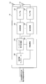
図10に示すように、無線基地局10は、測定部301と、UL信号受信処理部302と、制御部(スケジューラ)303と、DL信号生成部304と、マッピング部(割当て制御部)305と、を有している。
As shown in FIG. 10, the radio base station 10 includes a measurement unit 301, a UL signal reception processing unit 302, a control unit (scheduler) 303, a DL signal generation unit 304, a mapping unit (assignment control unit) 305, ,have.
測定部301(検出部)は、非ライセンスバンドにおいて他の送信ポイント(AP/TP)から送信される信号の検出/測定(LBT)を行う。具体的に、測定部301は、DL信号を送信する前等の所定タイミングで他の送信ポイントから送信される信号の検出/測定を行い、当該検出/測定の結果(LBT結果)を制御部303に出力する。例えば、測定部301は、検出した信号の電力レベルが所定の閾値以上であるか否かを判断して、当該判断結果(LBT結果)を制御部303に通知する。
The measurement unit 301 (detection unit) performs detection / measurement (LBT) of signals transmitted from other transmission points (AP / TP) in the non-licensed band. Specifically, the measurement unit 301 detects / measures a signal transmitted from another transmission point at a predetermined timing such as before transmitting the DL signal, and the control unit 303 indicates the detection / measurement result (LBT result). Output to. For example, the measurement unit 301 determines whether or not the power level of the detected signal is equal to or higher than a predetermined threshold, and notifies the control unit 303 of the determination result (LBT result).
また、測定部301は、DLにおけるリスニングだけでなく、ULにおけるリスニングを行うことも可能である。ユーザ端末側でULにおけるリスニングを行う場合には、測定部301はDLにおけるリスニングのみ行えばよい。なお、測定部301は、本発明に係る技術分野で用いられる測定器又は測定回路とすることができる。
In addition, the measurement unit 301 can perform not only listening in DL but also listening in UL. When performing UL listening on the user terminal side, the measurement unit 301 only needs to perform DL listening. The measuring unit 301 can be a measuring instrument or a measuring circuit used in the technical field according to the present invention.
UL信号受信処理部302は、ユーザ端末から送信されるUL信号(PUCCH、PUSCH、参照信号(SRS)等)に対して受信処理(例えば、複合処理や復調処理等)を行う。UL信号受信処理部302で取得した情報(例えば、上りリンクにおけるチャネル品質等)は制御部303に出力される。なお、UL信号受信処理部302は、本発明に係る技術分野で用いられる信号処理器又は信号処理回路とすることができる。
The UL signal reception processing unit 302 performs reception processing (for example, composite processing and demodulation processing) on UL signals (PUCCH, PUSCH, reference signal (SRS), etc.) transmitted from the user terminal. Information acquired by the UL signal reception processing unit 302 (for example, channel quality in the uplink) is output to the control unit 303. The UL signal reception processing unit 302 can be a signal processor or a signal processing circuit used in the technical field according to the present invention.
制御部(スケジューラ)303は、PDSCHで送信される下りデータ信号、PDCCH及び/又は拡張PDCCH(EPDCCH)で伝送される下り制御信号(UL grant/DL assignment)の無線リソースへの割当て(送信タイミング)を制御する。また、制御部303は、システム情報(PBCH)、同期信号(PSS/SSS)、下り参照信号(CRS、CSI-RS等)の割当て(送信タイミング)の制御も行う。なお、制御部303は、本発明に係る技術分野で用いられるコントローラ、スケジューラ、制御回路又は制御装置とすることができる。
The control unit (scheduler) 303 assigns downlink data signals transmitted on PDSCH, downlink control signals (UL grant / DL assignment) transmitted on PDCCH and / or enhanced PDCCH (EPDCCH) to radio resources (transmission timing) To control. The control unit 303 also controls allocation (transmission timing) of system information (PBCH), synchronization signals (PSS / SSS), and downlink reference signals (CRS, CSI-RS, etc.). The controller 303 can be a controller, scheduler, control circuit, or control device used in the technical field according to the present invention.
制御部303は、測定部301から出力されるLBT結果に基づいて、非ライセンスバンドにおけるDL信号の送信を制御する。また、制御部303は、ユーザ端末から送信される上り品質測定用の参照信号(SRS)に基づいてULのスケジューリングを制御する。また、制御部303は、ユーザ端末から送信される参照信号に基づいて、PDCCHの割当てにおいて各端末に割り当てるCCE/ECCE数(アグリゲーションレベル)や符号化率等を決定することができる。
The control unit 303 controls transmission of the DL signal in the non-licensed band based on the LBT result output from the measurement unit 301. Further, the control unit 303 controls UL scheduling based on a reference signal (SRS) for uplink quality measurement transmitted from the user terminal. Further, the control unit 303 can determine the number of CCE / ECCE (aggregation level) and coding rate assigned to each terminal in PDCCH assignment based on the reference signal transmitted from the user terminal.
ユーザ端末からフィードバックされる上り参照信号(SRS)は、ULにおけるLBT結果等に基づいて送信が制御されている。例えば、PUSCH/PUCCH送信の直前、又はSRS送信の直前にリスニングを行うことができる(図3参照)。また、PUSCH/PUCCH送信の直前、又はSRS送信に対して1つの周期・時間オフセットを用いてリスニングを行うことができる(図4参照)。
The transmission of the uplink reference signal (SRS) fed back from the user terminal is controlled based on the LBT result in the UL. For example, listening can be performed immediately before PUSCH / PUCCH transmission or immediately before SRS transmission (see FIG. 3). Also, listening can be performed immediately before PUSCH / PUCCH transmission or using one period / time offset for SRS transmission (see FIG. 4).
また、SRSが同一セル・サブフレームでPUSCH/PUCCHの送信がある場合のみ、ユーザ端末からSRSが送信されると仮定して制御することができる(図5A参照)。あるいは、SRSが送信されるサブフレームの次サブフレームでPUSCH/PUCCHの送信がある場合にユーザ端末からSRSが送信されると仮定して制御することができる(図6参照)。あるいは、LBTが不要となる長周期においてユーザ端末からSRSが送信されると仮定して制御することができる(図7参照)。
Also, control can be performed on the assumption that the SRS is transmitted from the user terminal only when the PURS / PUCCH is transmitted in the same cell subframe in the SRS (see FIG. 5A). Alternatively, the control can be performed on the assumption that the SRS is transmitted from the user terminal when PUSCH / PUCCH is transmitted in the next subframe of the subframe in which the SRS is transmitted (see FIG. 6). Alternatively, the control can be performed on the assumption that the SRS is transmitted from the user terminal in a long period in which the LBT is unnecessary (see FIG. 7).
DL信号生成部304は、制御部303からの指示に基づいてDL信号を生成する。DL信号としては、DL制御信号(PDCCH信号、EPDCCH信号、PSS/SSS信号、PBCH信号等)、下りデータ信号(PDSCH信号)、下り参照信号(CRS、CSI-RS、DM-RS等)等が挙げられる。また、DL信号生成部304は、DL-LBT結果がLBT_idleである場合にDL-BRSを生成してもよい。なお、DL信号生成部304は、本発明に係る技術分野で用いられる信号生成器又は信号生成回路とすることができる。
The DL signal generation unit 304 generates a DL signal based on an instruction from the control unit 303. DL signals include DL control signals (PDCCH signals, EPDCCH signals, PSS / SSS signals, PBCH signals, etc.), downlink data signals (PDSCH signals), downlink reference signals (CRS, CSI-RS, DM-RS, etc.), etc. Can be mentioned. Further, the DL signal generation unit 304 may generate a DL-BRS when the DL-LBT result is LBT_idle. The DL signal generation unit 304 can be a signal generator or a signal generation circuit used in the technical field according to the present invention.
また、マッピング部(割当て制御部)305は、制御部303からの指示に基づいて、DL信号のマッピング(割当て)を制御する。具体的に、マッピング部305は、測定部301から出力されるLBT結果によりDL信号が送信可能であると判断された場合、DL信号の割当てを行う。なお、マッピング部305は、本発明に係る技術分野で用いられるマッピング回路又はマッパーとすることができる。
The mapping unit (allocation control unit) 305 controls DL signal mapping (allocation) based on an instruction from the control unit 303. Specifically, the mapping unit 305 assigns a DL signal when it is determined that the DL signal can be transmitted based on the LBT result output from the measurement unit 301. The mapping unit 305 can be a mapping circuit or mapper used in the technical field according to the present invention.
図11は、本実施の形態に係るユーザ端末20の全体構成図である。ユーザ端末20は、MIMO伝送のための複数の送受信アンテナ201と、アンプ部202と、送受信部203(送信部/受信部)と、ベースバンド信号処理部204と、アプリケーション部205とを備えている。
FIG. 11 is an overall configuration diagram of the user terminal 20 according to the present embodiment. The user terminal 20 includes a plurality of transmission / reception antennas 201 for MIMO transmission, an amplifier unit 202, a transmission / reception unit 203 (transmission unit / reception unit), a baseband signal processing unit 204, and an application unit 205. .
下りリンクのデータについては、複数の送受信アンテナ201で受信された無線周波数信号がそれぞれアンプ部202で増幅され、送受信部203で周波数変換されてベースバンド信号に変換される。このベースバンド信号は、ベースバンド信号処理部204でFFT処理や、誤り訂正復号、再送制御(Hybrid ARQ)の受信処理等がなされる。この下りリンクのデータの内、下りリンクのユーザデータは、アプリケーション部205に転送される。アプリケーション部205は、物理レイヤやMACレイヤより上位のレイヤに関する処理等を行う。また、下りリンクのデータの内、報知情報もアプリケーション部205に転送される。
For downlink data, radio frequency signals received by a plurality of transmission / reception antennas 201 are each amplified by an amplifier unit 202, converted in frequency by a transmission / reception unit 203, and converted into a baseband signal. The baseband signal is subjected to FFT processing, error correction decoding, retransmission control (Hybrid ARQ) reception processing, and the like by the baseband signal processing unit 204. Among the downlink data, downlink user data is transferred to the application unit 205. The application unit 205 performs processing related to layers higher than the physical layer and the MAC layer. Also, broadcast information in the downlink data is also transferred to the application unit 205.
一方、上りリンクのユーザデータについては、アプリケーション部205からベースバンド信号処理部204に入力される。ベースバンド信号処理部204では、再送制御(Hybrid ARQ)の送信処理や、チャネル符号化、プリコーディング、DFT処理、IFFT処理等が行われて各送受信部203に転送される。
On the other hand, uplink user data is input from the application unit 205 to the baseband signal processing unit 204. The baseband signal processing unit 204 performs retransmission control (Hybrid ARQ) transmission processing, channel coding, precoding, DFT processing, IFFT processing, and the like, and forwards them to each transmission / reception unit 203.
送受信部203は、ベースバンド信号処理部204から出力されたベースバンド信号を無線周波数帯に変換する。その後、アンプ部202は、周波数変換された無線周波数信号を増幅して送受信アンテナ201により送信する。また、UL-LBT結果がLBT_idleである場合、送受信部203はUL-BRSを送信することも可能である。なお、送受信部(送信部/受信部)203は、本発明に係る技術分野で用いられるトランスミッター/レシーバー、送受信回路(送信回路/受信回路)又は送受信装置(送信装置/受信装置)とすることができる。
The transmission / reception unit 203 converts the baseband signal output from the baseband signal processing unit 204 into a radio frequency band. Thereafter, the amplifier unit 202 amplifies the frequency-converted radio frequency signal and transmits the amplified signal using the transmission / reception antenna 201. Further, when the UL-LBT result is LBT_idle, the transmission / reception unit 203 can also transmit UL-BRS. The transmission / reception unit (transmission unit / reception unit) 203 is a transmitter / receiver, a transmission / reception circuit (transmission circuit / reception circuit) or a transmission / reception device (transmission device / reception device) used in the technical field according to the present invention. it can.
図12は、ユーザ端末20が有するベースバンド信号処理部204の主な機能構成図である。なお、図12においては、本実施の形態における特徴部分の機能ブロックを主に示しており、ユーザ端末20は、無線通信に必要な他の機能ブロックも有しているものとする。
FIG. 12 is a main functional configuration diagram of the baseband signal processing unit 204 included in the user terminal 20. Note that FIG. 12 mainly shows functional blocks of characteristic portions in the present embodiment, and the user terminal 20 also has other functional blocks necessary for wireless communication.
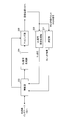
図12に示すように、ユーザ端末20は、測定部401(検出部)と、DL信号受信処理部402と、UL送信制御部403(制御部)と、UL信号生成部404と、マッピング部405と、を有している。なお、UL伝送におけるLBTを無線基地局側で行う場合には、測定部401を省略することができる。
As illustrated in FIG. 12, the user terminal 20 includes a measurement unit 401 (detection unit), a DL signal reception processing unit 402, a UL transmission control unit 403 (control unit), a UL signal generation unit 404, and a mapping unit 405. And have. In addition, when LBT in UL transmission is performed on the radio base station side, the measurement unit 401 can be omitted.
測定部401は、ULにおいて他の送信ポイント(AP/TP)から送信される信号の検出/測定(LBT)を行う。具体的に、測定部401は、UL信号を送信する直前等の所定タイミングで他の送信ポイントからの信号の検出/測定を行い、当該検出/測定結果(LBT結果)をUL送信制御部403に出力する。例えば、測定部401は、検出した信号の受信電力レベルが所定の閾値より大きいか否かを判断して、当該判断結果(LBT結果)をUL送信制御部403に通知する。なお、測定部401は、本発明に係る技術分野で用いられる測定器又は測定回路とすることができる。
The measurement unit 401 performs detection / measurement (LBT) of a signal transmitted from another transmission point (AP / TP) in the UL. Specifically, the measurement unit 401 detects / measures a signal from another transmission point at a predetermined timing such as immediately before transmitting a UL signal, and sends the detection / measurement result (LBT result) to the UL transmission control unit 403. Output. For example, the measurement unit 401 determines whether or not the received power level of the detected signal is greater than a predetermined threshold value, and notifies the UL transmission control unit 403 of the determination result (LBT result). The measuring unit 401 can be a measuring instrument or a measuring circuit used in the technical field according to the present invention.
例えば、測定部401は、PUSCH/PUCCH送信の直前、又はSRS送信の直前にリスニングを行うことができる(図3参照)。また、測定部401は、PUSCH/PUCCH送信の直前、又はSRS送信に対して1つの周期・時間オフセットを用いてリスニングを行うことができる(図4参照)。
For example, the measurement unit 401 can perform listening immediately before PUSCH / PUCCH transmission or immediately before SRS transmission (see FIG. 3). Moreover, the measurement part 401 can listen using one period and time offset immediately before PUSCH / PUCCH transmission, or SRS transmission (refer FIG. 4).
具体的には、測定部401は、PUSCH/PUCCHの送信を行わないサブフレームでSRSの送信が設定される場合、当該SRS送信前の所定タイミングでリスニングを実施する。所定タイミングとしては、SRSが配置される直前のタイミング(SRSが配置されるシンボルの一つ前のシンボルを含むタイミング)、又はPUSCH/PUCCHの送信を行う場合に実施するリスニングタイミングと同じタイミングとすることができる。
Specifically, when SRS transmission is set in a subframe in which PUSCH / PUCCH transmission is not performed, measurement unit 401 performs listening at a predetermined timing before the SRS transmission. As the predetermined timing, the timing immediately before the SRS is arranged (the timing including the symbol immediately before the symbol where the SRS is arranged), or the same timing as the listening timing to be performed when PUSCH / PUCCH is transmitted. be able to.
DL信号受信処理部402は、ライセンスバンド又は非ライセンスバンドで送信されるDL信号に対する受信処理(例えば、復号処理や復調処理等)を行う。例えば、DL信号受信処理部402は、下り制御信号(例えば、DCIフォーマット0、4)に含まれるULグラントを取得してUL送信制御部403に出力する。
The DL signal reception processing unit 402 performs reception processing (for example, decoding processing or demodulation processing) on the DL signal transmitted in the license band or the non-license band. For example, the DL signal reception processing unit 402 acquires the UL grant included in the downlink control signal (for example, DCI formats 0 and 4) and outputs the UL grant to the UL transmission control unit 403.
また、DL信号受信処理部402は、下り制御信号に含まれる非周期的SRS(A-SRS)のトリガ情報を検出した場合、UL送信制御部403に出力する。なお、DL信号受信処理部402は、本発明に係る技術分野で用いられる信号処理器又は信号処理回路とすることができる。
Also, when the DL signal reception processing unit 402 detects trigger information of an aperiodic SRS (A-SRS) included in the downlink control signal, the DL signal reception processing unit 402 outputs the trigger information to the UL transmission control unit 403. The DL signal reception processing unit 402 can be a signal processor or a signal processing circuit used in the technical field according to the present invention.
UL送信制御部403は、ライセンスバンドと非ライセンスバンド(又は、LBT設定キャリアとLBT非設定キャリア)において、無線基地局に対するUL信号(ULデータ、UL制御信号、参照信号等)の送信を制御する。また、UL送信制御部403は、測定部401からの検出/測定結果(LBT結果)に基づいて、非ライセンスバンドにおける送信を制御することができる。つまり、UL送信制御部403は、無線基地局から送信されるUL送信指示(ULグラント)と、測定部401からの検出結果(LBT結果)を考慮して、非ライセンスバンドにおけるUL信号の送信を制御する。
The UL transmission control unit 403 controls transmission of UL signals (UL data, UL control signals, reference signals, etc.) to the radio base station in the license band and non-license band (or LBT setting carrier and LBT non-setting carrier). . Further, the UL transmission control unit 403 can control transmission in the non-licensed band based on the detection / measurement result (LBT result) from the measurement unit 401. That is, the UL transmission control unit 403 considers the UL transmission instruction (UL grant) transmitted from the radio base station and the detection result (LBT result) from the measurement unit 401, and transmits the UL signal in the unlicensed band. Control.
また、PUSCH/PUCCHの送信を行わないサブフレームでSRSの送信が設定される場合、UL送信制御部403は、当該サブフレームにおけるSRSの送信を行わないように制御することができる。また、UL送信制御部403は、リスニング結果に基づいてPUSCH/PUCCHを送信するサブフレームにおいてSRSが設定されている場合に当該SRSを送信するよう制御することができる(図5A参照)。
In addition, when SRS transmission is set in a subframe that does not transmit PUSCH / PUCCH, the UL transmission control unit 403 can perform control so as not to transmit SRS in the subframe. Moreover, UL transmission control part 403 can be controlled to transmit the said SRS, when SRS is set in the sub-frame which transmits PUSCH / PUCCH based on the listening result (refer FIG. 5A).
また、PUSCH/PUCCHの送信を行わないサブフレームでSRSの送信が設定され、且つ当該サブフレームの次サブフレームでPUSCH/PUCCHの送信を行う場合、UL送信制御部403は、LBT結果に基づいてSRSの送信を制御することができる(図6参照)。また、SRSを所定周期(例えば、20ms)以上の長周期で送信する場合、UL送信制御部403は、リスニング結果に関わらずSRSを送信するように制御することができる(図7参照)。
Also, when SRS transmission is set in a subframe in which PUSCH / PUCCH transmission is not performed and PUSCH / PUCCH transmission is performed in the next subframe of the subframe, the UL transmission control section 403 is based on the LBT result. SRS transmission can be controlled (see FIG. 6). Moreover, when transmitting SRS with a long period more than a predetermined period (for example, 20 ms), UL transmission control part 403 can be controlled to transmit SRS irrespective of a listening result (refer FIG. 7).
UL信号生成部404は、UL送信制御部403からの指示に基づいてUL信号を生成する。UL信号としては、UL制御信号(PUCCH信号、PRACH信号等)、ULデータ信号(PUSCH信号)、参照信号(SRS、DM-RS等)等が挙げられる。また、UL-LBT結果がLBT_idleである場合、UL信号生成部404はUL-BRSを生成してもよい。なお、UL信号生成部404は、本発明に係る技術分野で用いられる信号生成器又は信号生成回路とすることができる。
The UL signal generation unit 404 generates a UL signal based on an instruction from the UL transmission control unit 403. Examples of UL signals include UL control signals (PUCCH signals, PRACH signals, etc.), UL data signals (PUSCH signals), reference signals (SRS, DM-RS, etc.), and the like. When the UL-LBT result is LBT_idle, the UL signal generation unit 404 may generate UL-BRS. The UL signal generation unit 404 can be a signal generator or a signal generation circuit used in the technical field according to the present invention.
また、マッピング部(割当て制御部)405は、UL送信制御部403からの指示に基づいて、UL信号のマッピング(割当て)を制御する。具体的に、マッピング部405は、測定部401から出力されるLBT結果によりUL信号が送信可能であると判断された場合、UL信号の割当てを行う。なお、マッピング部405は、本発明に係る技術分野で用いられるマッピング回路又はマッパーとすることができる。
The mapping unit (allocation control unit) 405 controls UL signal mapping (allocation) based on an instruction from the UL transmission control unit 403. Specifically, the mapping unit 405 assigns the UL signal when it is determined that the UL signal can be transmitted based on the LBT result output from the measurement unit 401. The mapping unit 405 can be a mapping circuit or mapper used in the technical field according to the present invention.
なお、上述した説明では、非ライセンスバンドセルがLBTの結果に応じてDL信号の送信可否を制御する場合を主に示したが本実施の形態はこれに限られない。例えば、LBTの結果に応じて、DFS(Dynamic Frequency Selection)により別キャリアに遷移する、又は送信電力制御(TPC)を行う場合であっても適用することができる。
In the above description, the case where the non-licensed band cell controls whether or not to transmit the DL signal according to the result of the LBT is mainly shown, but the present embodiment is not limited to this. For example, according to the result of LBT, it can be applied even when transitioning to another carrier by DFS (Dynamic Frequency Selection) or performing transmission power control (TPC).
以上、上述の実施形態を用いて本発明について詳細に説明したが、当業者にとっては、本発明が本明細書中に説明した実施形態に限定されるものではないということは明らかである。本発明は、特許請求の範囲の記載により定まる本発明の趣旨及び範囲を逸脱することなく修正及び変更態様として実施することができる。例えば、上述した複数の態様を適宜組み合わせて適用することができる。従って、本明細書の記載は、例示説明を目的とするものであり、本発明に対して何ら制限的な意味を有するものではない。
As described above, the present invention has been described in detail using the above-described embodiments. However, it is obvious for those skilled in the art that the present invention is not limited to the embodiments described in the present specification. The present invention can be implemented as modified and changed modes without departing from the spirit and scope of the present invention defined by the description of the scope of claims. For example, the above-described plurality of aspects can be applied in appropriate combination. Therefore, the description of the present specification is for illustrative purposes and does not have any limiting meaning to the present invention.
本出願は、2014年11月6日出願の特願2014-225677に基づく。この内容は、全てここに含めておく。
This application is based on Japanese Patent Application No. 2014-225677 filed on November 6, 2014. All this content is included here.