WO2016072067A1 - Cover for medical monitor - Google Patents
Cover for medical monitor Download PDFInfo
- Publication number
- WO2016072067A1 WO2016072067A1 PCT/JP2015/005426 JP2015005426W WO2016072067A1 WO 2016072067 A1 WO2016072067 A1 WO 2016072067A1 JP 2015005426 W JP2015005426 W JP 2015005426W WO 2016072067 A1 WO2016072067 A1 WO 2016072067A1
- Authority
- WO
- WIPO (PCT)
- Prior art keywords
- medical monitor
- protection member
- attaching member
- medical
- attaching
- Prior art date
- Legal status (The legal status is an assumption and is not a legal conclusion. Google has not performed a legal analysis and makes no representation as to the accuracy of the status listed.)
- Ceased
Links
Images






Classifications
-
- A—HUMAN NECESSITIES
- A61—MEDICAL OR VETERINARY SCIENCE; HYGIENE
- A61B—DIAGNOSIS; SURGERY; IDENTIFICATION
- A61B46/00—Surgical drapes
- A61B46/10—Surgical drapes specially adapted for instruments, e.g. microscopes
-
- G—PHYSICS
- G06—COMPUTING OR CALCULATING; COUNTING
- G06F—ELECTRIC DIGITAL DATA PROCESSING
- G06F1/00—Details not covered by groups G06F3/00 - G06F13/00 and G06F21/00
- G06F1/16—Constructional details or arrangements
- G06F1/1601—Constructional details related to the housing of computer displays, e.g. of CRT monitors, of flat displays
- G06F1/1607—Arrangements to support accessories mechanically attached to the display housing
-
- G—PHYSICS
- G06—COMPUTING OR CALCULATING; COUNTING
- G06F—ELECTRIC DIGITAL DATA PROCESSING
- G06F2200/00—Indexing scheme relating to G06F1/04 - G06F1/32
- G06F2200/16—Indexing scheme relating to G06F1/16 - G06F1/18
- G06F2200/161—Indexing scheme relating to constructional details of the monitor
- G06F2200/1612—Flat panel monitor
Definitions
- the protection member has a portion that is convex in the direction away from the medical monitor. On the convex portion, medicines and the like cannot be placed. Therefore, a cause of contamination or the like can be eliminated. Further, by attaching the cover to a medical monitor, the medical monitor can be protected from contamination and external damages.
- the cover 20 representing an animal or the like is attached to the medical monitor 10 as shown in Fig. 2. This can relieve inherent stress that an infant, a child, or their families may feel from an atmosphere of a hospital. Moreover, a pediatric ward, an obstetrics and gynecology ward, an NICU, or the like where this medical monitor 10 is used can be made to have a positive atmosphere.
- the guide rail 211 has one or more convex portions 212.
- the convex portions 212 are provided to extend in the longitudinal direction (X-axis direction) of the display screen 11 of the medical monitor 10.
- the convex portions 212 are provided to correspond to concave portions 223 of the protection member 22.
- Fig. 6A shows a configuration in which protection members 22 representing ears of a cat are connected to the upper side of the medical monitor 10, and another protection member 22 representing a tail of a cat is connected to a lateral side of the medical monitor 10. Therefore, when viewed from the front, the medical monitor 10 looks like a cat as shown in Fig. 6A.
- the protection member 22 representing a tail is formed by a material having a rigidity with which the protection member 22 can withstand a load of about several hundreds of grams.
- the protection member 22 provided on the lateral side of the medical monitor 10 is preferably made of a material having higher rigidity than the protection members 22 placed on the upper side of the medical monitor 10.
- Fig. 7 shows a configuration in which a protection member 22 representing the entire body of a dog is connected to the upper side of the medical monitor 10.
- the medical monitor 10 looks like as if a dog is mounted on the medical monitor 10 as shown in Fig. 7.
- portions corresponding to the front and rear legs of a dog are configured as clamping portions 227 (227-1, 227-3).
- the clamping portion 227-1 corresponding to the left front leg, and a clamping portion 227-2 (not shown) corresponding to the right front leg are paired.
- the pair of clamping portion 227 are configured to be openable and closable.
- the clamping portion 227-1 is urged so as to close from the -Z direction to the +Z direction.
- the clamping portion 227-2 which is not shown is urged so as to close from the +Z direction to the -Z direction. Therefore, a configuration may be employed where an elastic member or the like that imparts elasticity in a direction along which the medical monitor 10 is clamped is formed in the protection member 22.
- clamping portion 227-3 corresponding to the left rear leg, and a clamping portion 227-4 (not shown) corresponding to the right rear leg are paired.
- the clamping portion 227-3 is urged so as to close from the -Z direction to the +Z direction.
- the clamping portion 227-4 which is not shown is urged so as to close from the +Z direction to the -Z direction.
- the protection member 22 may be configured so as to have the pair of clamping portions 227.
- the clamping portions 227 have the configuration where the protection member 22 is fixed to the medical monitor 10 by clamping the medical monitor 10 from the both sides (in the example of Fig. 7, in the +Z and -Z directions). That is, the protection member 22 has the configuration where the member is supported by the attaching member 21, and also by the clamping portions 227. According to the configuration, the protection member 22 can be fixed more firmly to the medical monitor 10.
Landscapes
- Engineering & Computer Science (AREA)
- Health & Medical Sciences (AREA)
- Theoretical Computer Science (AREA)
- General Engineering & Computer Science (AREA)
- Life Sciences & Earth Sciences (AREA)
- Surgery (AREA)
- Biomedical Technology (AREA)
- Molecular Biology (AREA)
- Physics & Mathematics (AREA)
- Human Computer Interaction (AREA)
- Computer Hardware Design (AREA)
- Heart & Thoracic Surgery (AREA)
- Medical Informatics (AREA)
- General Physics & Mathematics (AREA)
- Animal Behavior & Ethology (AREA)
- General Health & Medical Sciences (AREA)
- Public Health (AREA)
- Veterinary Medicine (AREA)
- Measuring And Recording Apparatus For Diagnosis (AREA)
- Devices For Indicating Variable Information By Combining Individual Elements (AREA)
Abstract
A cover for a medical monitor is provided. The cover includes at least one attaching member configured to be fixed to the medical monitor such that the at least one attaching member is tightly attached to the medical monitor, and a protection member. The attaching member has a connecting portion. The protection member is configured to be attached to the connecting portion of the attaching member. The protection member has a portion that is convex in a direction away from the medical monitor.
Description
The present invention relates to a cover for a medical monitor.
Medical monitors for monitoring blood pressure, body temperature and the like have a rigid housing to prevent internal damage and internal failure. For example, EP2180773A1 discloses a device having a sterilizable housing. However, a usage state of medical monitors varies depending on hospitals and patients, and sometimes, a scratch, a crack, a dent or the like is formed on a housing of a medical monitor.
Restoring a damaged portion of a housing of a medical monitor is difficult, and imposes a great financial burden on a user who requests the restoration.
Medical monitors are used at medical sites such as hospitals, where hygienic considerations (i.e., cleanliness) are required with respect to devices used therein. Depending on the usage state, however, there are situations where a surface of a medical monitor is contaminated by bodily fluid, blood or the like of a patient, in which case a medical personnel has to adequately clean the medical monitor.
As such, there are increasing needs for protecting a housing of a medical monitor from external damages (such as a scratch, a dent, and a crack) and contamination.
Illustrative aspects of the present invention provide a cover for a medical monitor configured to protect a housing from external damages (such as a scratch, a dent, and a crack) and contamination.
According to an illustrative aspect of the present invention, a cover for a medical monitor is provided. The cover includes at least one attaching member configured to be fixed to the medical monitor such that the at least one attaching member is tightly attached to the medical monitor, and a protection member. The attaching member has a connecting portion. The protection member is configured to be attached to the connecting portion of the attaching member. The protection member has a portion that is convex in a direction away from the medical monitor.
As described above, the protection member has a portion that is convex in the direction away from the medical monitor. On the convex portion, medicines and the like cannot be placed. Therefore, a cause of contamination or the like can be eliminated. Further, by attaching the cover to a medical monitor, the medical monitor can be protected from contamination and external damages.
Hereinafter, an exemplary embodiment of the invention will be described with reference to the drawings. Fig. 1 is an external view of a medical monitor 10 to which a cover 20 according to one or more exemplary embodiments of the present invention is to be attached. The medical monitor 10 has a liquid crystal display panel to display various waveforms (a respiratory waveform, a blood pressure waveform and the like) and measurement values (SpO2 value, body temperature and the like). The medical monitor 10 is connected to a subject (patient) through various cables to obtain values of parameters.
The medical monitor 10 has a display screen 11 on which various waveforms and measurement values are displayed, and a housing frame 12 provided around the display screen 11. In the following description, an X-axis is an axis parallel to the long-side direction of the liquid crystal display panel, a Y-axis is an axis parallel to the short-side direction of the liquid crystal display panel, and a Z-axis is an axis parallel to the thickness direction the liquid crystal display panel. The use of the medical monitor 10 is not particularly limited. According to one or more exemplary embodiments described below, the medical monitor 10 may be use, for example, in a pediatrics department, an obstetrics and gynecology department, or a neonatal intensive care unit (NICU).
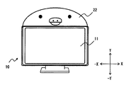
Fig. 2 is a view illustrating a cover 20 attached to the medical monitor 10. The cover 20 includes an attaching member 21 and protection members 22. The attaching member 21 is fixed the medical monitor 10, more specifically, to the housing frame 12 of the medical monitor 10 so as to cover a portion of the housing frame 12. The attaching member 21 has a portion that is tightly attached to the medical monitor 10. The attaching member 21 is made of soft and elastic material, such as synthetic rubber, soft vinyl chloride, or an elastomer. Alternatively, the attaching member 21 may be configured such that the soft and elastic material (synthetic rubber, soft vinyl chloride, an elastomer, or the like) is covered with a member having a cushioning property.
When attaching the attaching member 21 to the housing frame 12, a medical personnel stretches the attaching member 21 by, for example, pulling the attaching member 21 by hands, and causes the attaching member 21 to be tightly attached to the housing frame 12 by releasing the attaching member 21 from hands.
The attaching member 21 may be made of a material other than the materials described above in so far as the material can be tightly attached to the housing frame 12 of the medical monitor 10. For example, the material of the attaching member 21 may be silicone or the like.
The protection members 22 are configured to be attachable to the attaching member 21. Each of the protection members 22 has a portion that is convex in a direction away from the medical monitor 10. The method of fixing together the attaching member 21 and the protection member 22 will be described later with reference to Figs. 3 to 4B.
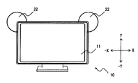
In the example of Fig. 2, each protection member 22 has a shape representing ears of a mouse, and is configured to be convex in the +Y direction and the +X and -X directions. The protection member 22 may have a different shape representing a portion (or an entirety) of an animal or animation character that may generally give a favorable impression to an infant or the like.
The protection member 22 has a metal rod, wire or the like extending inside to maintain its shape (e.g., the shape representing ears of a mouse) also after being attached to the attaching member 21. It is preferable that the metal rod be made of a material that can be bent when a force is applied thereto, so that it does not harm an infant or a child even the a hand or a body of the infant or the child hits the protection member 22. The protection member 22 is configured such that the metal rod is covered with a bag body (e.g., a bag body 222 which will be described later) stuffed with cushioning material (e.g., natural feathers or low-repulsive polyurethane foam tips). The bag body stuffed with the cushioning material may be colored or provided by stitching together a plurality of colored fabric pieces to provide an appearance resembling an animal, an animation character, or the like.
The cover 20 representing an animal or the like is attached to the medical monitor 10 as shown in Fig. 2. This can relieve inherent stress that an infant, a child, or their families may feel from an atmosphere of a hospital. Moreover, a pediatric ward, an obstetrics and gynecology ward, an NICU, or the like where this medical monitor 10 is used can be made to have a positive atmosphere.
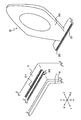
Next, an example of a connection between the attaching member 21 and the protection member 22 will be described with reference to Fig. 3. Fig. 3 is an enlarged view of an area of an upper right corner (one of the four corners in the +X and +Y directions) of the medical monitor 10. An upper portion of the attaching member 21 has a guide rail 211 extending in the X-axis direction. The guide rail 211 is an example of the connecting portion to which the protection member 22 is connected.
The guide rail 211 has one or more convex portions 212. The convex portions 212 are provided to extend in the longitudinal direction (X-axis direction) of the display screen 11 of the medical monitor 10. The convex portions 212 are provided to correspond to concave portions 223 of the protection member 22.
The protection member 22 has a slider portion 221 configured to be fitted to the guide rail 211 of the attaching member 21, and the bag body 222 provided on the slider portion 221. The slider portion 221 has the concave portions 223 having a shape corresponding to the convex portions 212 on the guide rail 211. In the example of Fig. 3, three convex portions 212 are provided on the guide rail 211, and therefore three concave portions 223 (partially not shown) are provided on the slider portion 221. A medical personnel slides the protection member 22 in the X-axis direction in a state in which the concave portions 223 and the convex portions 212 are engaged with each other, to attach or detach the protection member 22 with respect to the attaching member 21.
While the convex portions 212 are provided on the guide rail 211 in the example of Fig. 3, the present invention is not limited to this example. For example, the guide rail 211 may have one or more concave portions, and one or more convex portions may be provided on the slider portion 221. Alternatively, concave and convex portions may be provided on the guide rail 211, and the slider portion 221 may have convex and concave portions corresponding to the guide rail 211. That is, the guide rail 211 has a concave and convex structure extending in the X-axis direction, and the slider portion 221 has an elongated concave and convex structure corresponding to the elongated concave and convex structure of the guide rail 211.
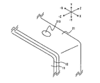
Next, another example of a connection between the attaching member 21 and the protection member 22 will be described with reference to Figs. 4A and 4B. Fig. 4A is an enlarged view of an area of the upper right corner (one of the four corners in the +X and +Y directions) of the medical monitor 10. An engagement hole 213 is provided in the attaching member 21. The engagement hole 213 is another example of the connecting portion for fixing the protection member 22 to the attaching member 21.
The attaching member 21 has the engagement hole 213 on its surface. The distal end of the protection member 22 is inserted into the engagement hole 213. The engagement hole 213 is a non-through hole (a hole with a bottom). An example of the engagement hole 213 will be described with reference to Fig. 4B.
Fig. 4B is a view showing a Y-(-Y) section in a state in which the protection member 22 is inserted into the attaching member 21. The engagement hole 213 has an opening portion 2131 and a cavity portion 2132. The opening portion 2131 has a width (length in the X-axis direction) that is narrower than the width (length in the X-axis direction) of the cavity portion 2132. A pair of convex portions 2133 are provided to reduce the width of the opening portion 2131. A distal end portion 224 of the protection member 22 is inserted and fitted into the cavity portion 2132. The protection member 22 is supported by the convex portions 2133 forming the opening portion 2131 of the engagement hole 213. The protection member 22 has an arm 225 having a smaller diameter than the distal end portion 224. The pair of convex portions 2133 forming the opening portion 2131 support the arm 225 from the both sides, and therefore the protection member 22 is fixed upright in the direction (in the example, +Y direction) opposite to the direction (in the example, -Y direction) in which the cavity portion 2132 is formed. In order to more firmly fix the arm 225 to the opening portion 2131, preferably, the arm 225 is configured by a robust material (e.g., a rigid metal, synthetic rubber having a Young's modulus of a constant value or larger, or the like).
In the above, the cavity portion 2132 has been described to have a substantially square sectional shape. The present invention is not limited to this. The cavity portion 2132 may have a substantially circular sectional shape, or the like.
In Fig. 4A, which is an enlarged view, only one engagement hole 213 is shown. However, a plurality of engagement holes 213 may be provided in the attaching member 21. In accordance with the shape (e.g., the kind of an animal) of the protection member 22 to be attached, a medical personnel may determine an engagement hole 213 into which the protection member 22 is to be attached.
The connection between the attaching member 21 and the protection member 22 is not limited to the examples shown in Figs. 3 to 4B. Other examples of the connection include a hook and loop fastener, a button and the like. That is, any type of connection may be provided in far as the protection member 22 can be fixed to the medical monitor 10 by connecting the attaching member 21 to the protection member 22 through the connecting portion on the attaching member 21.
While Fig. 3 illustrates an example in which the protection member 22 having the bag body 222 representing an ear of a rabbit is fixed (connected) to the attaching member 21, the protection member 22 having the bag body 222 of a different shape (e.g., a shape of an ear of a cat) may be fixed (connected) to the attaching member 21. Considering the sex, age, preference, and the like of a patient for whom the medical monitor 10 is to be used, a medical personnel may connect the protection member 22 having the bag body 222 having the most preferred shape, to the attaching member 21.
Variations of the protection member 22 will be described. Figs. 5A to 7 are views illustrating variations of the protection member 22. Fig. 5A illustrates a configuration in which protection members 22 representing ears of a rabbit are connected to the upper side of the medical monitor 10. The display screen 11 of the medical monitor 10 has a substantially laterally long rectangular shape. Therefore, when viewed from the front, the medical monitor 10 looks like a face of a rabbit as shown in Fig. 5A.
Similarly, Fig. 5B shows a configuration in which protection members 22 representing ears of a mouse are connected to the upper side of the medical monitor 10. When viewed from the front, the medical monitor 10 looks like a face of a mouse as shown in Fig. 5B. Additionally, a screen saver conforming to the shape of the protection member 22 may operate in accordance with the setting of the medical monitor 10. For example, the medical personnel may set a screen saver conforming to the shape of the protection member 22 so that, when the medical monitor 10 is in a sleep mode, the screen saver conforming to the shape of the protection member 22 appears. In the case where the protection members 22 have a shape representing ears of a mouse, for example, a face of a mouse may be displayed as the screen saver.
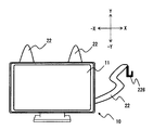
Fig. 6A shows a configuration in which protection members 22 representing ears of a cat are connected to the upper side of the medical monitor 10, and another protection member 22 representing a tail of a cat is connected to a lateral side of the medical monitor 10. Therefore, when viewed from the front, the medical monitor 10 looks like a cat as shown in Fig. 6A. Preferably, the protection member 22 representing a tail is formed by a material having a rigidity with which the protection member 22 can withstand a load of about several hundreds of grams. In other words, the protection member 22 provided on the lateral side of the medical monitor 10 is preferably made of a material having higher rigidity than the protection members 22 placed on the upper side of the medical monitor 10. The medical personnel may hang a light medical device such as a stethoscope or a cord of the medical monitor 10 on the protection member 22 (tail) to keep it in place. Alternatively, a hook 226 may be provided on the protection member 22 representing a tail. The hook 226 may be configured such that a light medical device such as a stethoscope or a cord of the medical monitor 10 may be hanged thereon to keep it in place.
Fig. 6B shows a configuration in which a protection member 22 representing a head of a chick is connected to the upper side of the medical monitor 10. When viewed from the front, the medical monitor 10 looks like a chick as shown in Fig. 6B.
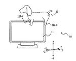
Fig. 7 shows a configuration in which a protection member 22 representing the entire body of a dog is connected to the upper side of the medical monitor 10. When viewed from the front, the medical monitor 10 looks like as if a dog is mounted on the medical monitor 10 as shown in Fig. 7.
Preferably, portions corresponding to the front and rear legs of a dog are configured as clamping portions 227 (227-1, 227-3). In the clamping portions 227, the clamping portion 227-1 corresponding to the left front leg, and a clamping portion 227-2 (not shown) corresponding to the right front leg are paired. The pair of clamping portion 227 are configured to be openable and closable. The clamping portion 227-1 is urged so as to close from the -Z direction to the +Z direction. The clamping portion 227-2 which is not shown is urged so as to close from the +Z direction to the -Z direction. Therefore, a configuration may be employed where an elastic member or the like that imparts elasticity in a direction along which the medical monitor 10 is clamped is formed in the protection member 22.
Similarly, the clamping portion 227-3 corresponding to the left rear leg, and a clamping portion 227-4 (not shown) corresponding to the right rear leg are paired. The clamping portion 227-3 is urged so as to close from the -Z direction to the +Z direction. The clamping portion 227-4 which is not shown is urged so as to close from the +Z direction to the -Z direction.
As described above, the protection member 22 is fixed to the medical monitor 10 so that the clamping portions 227 clamp the medical monitor 10 in the -Z and +Z directions. Therefore, the protection member 22 is fixed to the medical monitor 10 by the clamping portions 227 in addition to the connecting portion of the attaching member 21. Consequently, the protection member 22 can be fixed more firmly to the medical monitor 10.
Another example of the attaching member 21 will be described with reference to Fig. 8. The attaching member 21 is configure to be fitted to the four corners of the medical monitor 10. As illustrated, the attaching member 21 has four members 21-1, 21-2, 21-3, 21-4. For example, each of the attaching members 21-1, 21-2, 21-3, 21-4 has a groove portion (not shown) on a side contacting the medical monitor 10, and the width of the groove portion substantially corresponds to the width in the Z-axis direction of the medical monitor 10. The attaching members 21-1, 21-2, 21-3, 21-4 are fixed to the medical monitor 10 by fitting the respective groove portions to the four corners of the housing frame 12 of the medical monitor 10. Protection members 22 may be fixed to the attaching members 21-1, 21-2 in a similar manner as those described above (e.g., as illustrated in Figs. 3 to 4B).
Advantages of the medical monitor cover 20 of the exemplary embodiment will be described. The medical monitor cover 20 has the attaching member 21 configured to be attached and fixed to the medical monitor 10, and the protection member 22 configured to be connected to the attaching member 21 and having a portion that is convex in the direction away from the medical monitor 10. In the examples of Figs. 5A to 7, the protection members 22 have the portions (e.g., tip end portions of ears of a rabbit or a mouse) that are convex in the upward direction (the +Y direction) from the upper side of the medical monitor 10, respectively. Medicines, materials, or the like which are used in a medical site cannot be placed on the convex portions, and therefore a cause of contamination or the like can be eliminated. In each of the protection members 22, moreover, the surface is configured by the bag body 222. Therefore, water can be absorbed, and the medical monitor 10 can be protected from a scratch, contamination, and the like.
Particularly, the protection member 22 shown in Fig. 6B is configured to cover the entire upper side of the medical monitor 10, and is convex in the upward direction (the +Y direction). According to this configuration, the protection member 22 can exhaustively protect the upper portion of the medical monitor 10 (avoidance from, for example, contamination, a scratch, water, and placement of medicines or the like).
The attaching member 21 and the protection member 22 are detachably attached together. Therefore, in a case where the protection member 22 is contaminated, they can be easily detached and washed/cleaned. Consequently, the medical monitor 10 can be kept clean. Moreover, the protection member 22 has a shape representing the ear or the like of an animal. Therefore, the protection member 22 can be replaced with another one in accordance with the preference of the infant or the like for whom the medical monitor 10 is to be used. Consequently, it is possible to reduce the stress which may be felt from the atmosphere of the hospital by the infant or the like.
As shown in Fig. 7, the protection member 22 may be configured so as to have the pair of clamping portions 227. The clamping portions 227 have the configuration where the protection member 22 is fixed to the medical monitor 10 by clamping the medical monitor 10 from the both sides (in the example of Fig. 7, in the +Z and -Z directions). That is, the protection member 22 has the configuration where the member is supported by the attaching member 21, and also by the clamping portions 227. According to the configuration, the protection member 22 can be fixed more firmly to the medical monitor 10.
As shown in Fig. 3, the connecting portion (the place to be connected to the protection member 22) of the attaching member 21 is preferably configured by the guide rail 211. The guide rail 211 and the slider portion 221 have the corresponding convex and concave shapes, respectively, and therefore the protection member 22 can be correctly fixed to the attaching member 21 (therefore, the medical monitor 10). In other words, even when a pressure in the Z-axis direction is applied to the protection member 22, it is possible to prevent the protection member 22 from being detached from the medical monitor 10. The attachment and detachment of the protection member 22 can be realized only by parallel movement (in the example of Fig. 3, movement in the X-axis direction). Therefore, the trouble of attachment and detachment can be largely reduced.
While the present invention has been described with reference to certain exemplary embodiments thereof, the scope of the present invention is not limited to the exemplary embodiments described above, and it will be understood by those skilled in the art that various changes and modifications may be made therein without departing from the scope of the present invention as defined by the appended claims.
Although the effect that the kind of the animal or the like can be easily changed is lost, also a configuration where the attaching member 21 and the protection member 22 are connected to each other by stitching may be employed. That is, even in a configuration where the attaching member 21 and the protection member 22 are integrated with each other, it is possible to protect the medical monitor 10 from external damages and contamination.
Although, in the above, the medical monitor 10 which is used mainly in a stationary manner in a ward or the like has been described, the invention is not limited to this. For example, the medical monitor 10 may be a medical transmitter having a wireless function. Fig. 9 is a view schematically showing a case where a medical monitor cover 20 is attached to a medical monitor 10 of the transmitter type. As illustrated, the attaching member 21 is tightly attached to an outer frame of the portable medical monitor 10. The protection member 22 representing the ears and head of a sheep is attached to the medical monitor 10 (transmitter). According to the configuration, it is possible to prevent medical solution or the like from adhering to the body of the medical monitor 10. The medical monitor has a cute appearance. This causes an infant or the like to carefully handle the medical monitor 10, and therefore the normal operation and long-life period of the medical monitor 10 are attained.
While hatching is partially omitted in the drawings discussed above, this is to further clarify the appearances of the medical monitor 10 and the medical monitor cover 20. Therefore, existence/non-existence of hatching does not affect the scope of the claims.
This application is based on Japanese Patent Application No. 2014-226639 filed on November 7, 2014, the entire content of which is incorporated herein by reference.
Claims (7)
- A cover for a medical monitor, the cover comprising:
at least one attaching member configured to be fixed to the medical monitor such that the at least one attaching member is tightly attached to the medical monitor, the attaching member comprising a connecting portion; and
a protection member configured to be attached to the connecting portion of the attaching member, the protection member comprising a portion that is convex in a direction away from the medical monitor. - The cover according to claim 1, wherein the attaching member and the protection member are configured to be detachably attached together.
- The cover according to claim 1 or 2, wherein the connecting portion comprises a guide rail having an elongated concave and convex structure, and
the protection member comprises a slider portion having a shape corresponding to the concave and convex structure of the guide rail. - The cover according to any one of claims 1 to 3, wherein the protection member is configured to cover an entire upper side of the medical monitor.
- The cover according to any one of claims 1 to 4, wherein the protection member has a pair of clamping portions configured to clamp the medical monitor from both sides.
- The cover according to any one of claims 1 to 5, wherein the attaching member is fixed to the medical monitor such that the attaching member is fitted to four corners of the medical monitor.
- The cover according to any one of claims 1 to 6, wherein the protection member has a shape representing an ear or a whole body of an animal.
Applications Claiming Priority (2)
| Application Number | Priority Date | Filing Date | Title |
|---|---|---|---|
| JP2014-226639 | 2014-11-07 | ||
| JP2014226639A JP2016092659A (en) | 2014-11-07 | 2014-11-07 | Medical monitor cover |
Publications (1)
| Publication Number | Publication Date |
|---|---|
| WO2016072067A1 true WO2016072067A1 (en) | 2016-05-12 |
Family
ID=54542483
Family Applications (1)
| Application Number | Title | Priority Date | Filing Date |
|---|---|---|---|
| PCT/JP2015/005426 Ceased WO2016072067A1 (en) | 2014-11-07 | 2015-10-28 | Cover for medical monitor |
Country Status (2)
| Country | Link |
|---|---|
| JP (1) | JP2016092659A (en) |
| WO (1) | WO2016072067A1 (en) |
Citations (6)
| Publication number | Priority date | Publication date | Assignee | Title |
|---|---|---|---|---|
| US5464214A (en) * | 1994-05-06 | 1995-11-07 | Griffin; Tom | Device for enhancing the appeal of a video terminal |
| US6845775B1 (en) * | 1999-09-20 | 2005-01-25 | Michel Barthes | Surgical viewing device with display screen capable of being sterilized |
| US20080103637A1 (en) * | 2006-10-30 | 2008-05-01 | Bliven Robert P | Method and structures for attaching accessories to an electronic device |
| EP2180773A1 (en) | 2008-10-22 | 2010-04-28 | Arthrex, Inc. | Portable electronic device assembly having sterilizable housing |
| GB2490046A (en) * | 2008-02-22 | 2012-10-17 | Hewlett Packard Development Co | Peripheral device with data connection foot for mounting said device to display unit housing |
| US20130148270A1 (en) * | 2011-12-12 | 2013-06-13 | Robb Fujioka | Electronic device case with removable attachments |
Family Cites Families (2)
| Publication number | Priority date | Publication date | Assignee | Title |
|---|---|---|---|---|
| JP2003135405A (en) * | 2001-11-07 | 2003-05-13 | Omron Corp | Health equipment |
| JP2003209766A (en) * | 2002-01-15 | 2003-07-25 | Yuukashiya:Kk | Stereoscopic decorative applique fused to display housing |
-
2014
- 2014-11-07 JP JP2014226639A patent/JP2016092659A/en active Pending
-
2015
- 2015-10-28 WO PCT/JP2015/005426 patent/WO2016072067A1/en not_active Ceased
Patent Citations (6)
| Publication number | Priority date | Publication date | Assignee | Title |
|---|---|---|---|---|
| US5464214A (en) * | 1994-05-06 | 1995-11-07 | Griffin; Tom | Device for enhancing the appeal of a video terminal |
| US6845775B1 (en) * | 1999-09-20 | 2005-01-25 | Michel Barthes | Surgical viewing device with display screen capable of being sterilized |
| US20080103637A1 (en) * | 2006-10-30 | 2008-05-01 | Bliven Robert P | Method and structures for attaching accessories to an electronic device |
| GB2490046A (en) * | 2008-02-22 | 2012-10-17 | Hewlett Packard Development Co | Peripheral device with data connection foot for mounting said device to display unit housing |
| EP2180773A1 (en) | 2008-10-22 | 2010-04-28 | Arthrex, Inc. | Portable electronic device assembly having sterilizable housing |
| US20130148270A1 (en) * | 2011-12-12 | 2013-06-13 | Robb Fujioka | Electronic device case with removable attachments |
Also Published As
| Publication number | Publication date |
|---|---|
| JP2016092659A (en) | 2016-05-23 |
Similar Documents
| Publication | Publication Date | Title |
|---|---|---|
| US20130096405A1 (en) | Fingertip pulse oximeter | |
| JP6577753B2 (en) | EEG measurement device | |
| US8386003B2 (en) | Portable medical device | |
| CN110536633B (en) | ECG sensor | |
| EP3097949B1 (en) | Case for medical equipment | |
| US20190274626A1 (en) | Harness mounted patient monitoring system and method | |
| WO2016072067A1 (en) | Cover for medical monitor | |
| EP3634221B1 (en) | Pulse meter for newborn | |
| JP5148370B2 (en) | Stethoscope holder | |
| CN211796557U (en) | Stethoscope for cardiovascular medicine | |
| CN211023382U (en) | Restraint gloves with temper function | |
| CN115736947A (en) | Wireless brain electricity monitoring pillow | |
| CN213129475U (en) | Fixing device and oxyhemoglobin saturation monitoring equipment | |
| CN206167418U (en) | Pacificating nipple | |
| CN203196096U (en) | Infant infusion fixator | |
| CN206183464U (en) | Restraint assemblage zone | |
| CN216455049U (en) | Head fixing device for enhanced CT patient | |
| CN223126727U (en) | Novel restraint tool | |
| CN218501086U (en) | Indwelling needle protection glove assembly for infants and young children | |
| CN223601788U (en) | Child hand remaining needle protection device | |
| KR200482583Y1 (en) | Cushion for hair washing bowl | |
| CN211326374U (en) | A neonatal incubator | |
| CN205548916U (en) | Lateral position bolster is used in operation | |
| CN220631781U (en) | Neonate positive side position fixing pillow | |
| CN223910348U (en) | Newborn weight weighing auxiliary air cushion |
Legal Events
| Date | Code | Title | Description |
|---|---|---|---|
| 121 | Ep: the epo has been informed by wipo that ep was designated in this application |
Ref document number: 15794657 Country of ref document: EP Kind code of ref document: A1 |
|
| NENP | Non-entry into the national phase |
Ref country code: DE |
|
| 122 | Ep: pct application non-entry in european phase |
Ref document number: 15794657 Country of ref document: EP Kind code of ref document: A1 |