WO2016060101A1 - Dispositif d'émission, procédé d'émission, dispositif de réception et procédé de réception - Google Patents
Dispositif d'émission, procédé d'émission, dispositif de réception et procédé de réception Download PDFInfo
- Publication number
- WO2016060101A1 WO2016060101A1 PCT/JP2015/078875 JP2015078875W WO2016060101A1 WO 2016060101 A1 WO2016060101 A1 WO 2016060101A1 JP 2015078875 W JP2015078875 W JP 2015078875W WO 2016060101 A1 WO2016060101 A1 WO 2016060101A1
- Authority
- WO
- WIPO (PCT)
- Prior art keywords
- encoded data
- audio
- stream
- predetermined number
- data
- Prior art date
Links
- 230000005540 biological transmission Effects 0.000 title claims abstract description 60
- 238000000034 method Methods 0.000 title claims description 53
- 238000012545 processing Methods 0.000 claims description 39
- 238000003780 insertion Methods 0.000 claims description 15
- 230000037431 insertion Effects 0.000 claims description 15
- 239000000284 extract Substances 0.000 claims description 10
- 238000004458 analytical method Methods 0.000 description 18
- 238000005516 engineering process Methods 0.000 description 14
- 239000000872 buffer Substances 0.000 description 13
- 238000009877 rendering Methods 0.000 description 13
- 101150109471 PID2 gene Proteins 0.000 description 9
- 238000013507 mapping Methods 0.000 description 7
- 101100190466 Caenorhabditis elegans pid-3 gene Proteins 0.000 description 6
- 238000005070 sampling Methods 0.000 description 6
- 101000609957 Homo sapiens PTB-containing, cubilin and LRP1-interacting protein Proteins 0.000 description 4
- 102100039157 PTB-containing, cubilin and LRP1-interacting protein Human genes 0.000 description 4
- 238000004364 calculation method Methods 0.000 description 4
- 238000010586 diagram Methods 0.000 description 4
- 238000004519 manufacturing process Methods 0.000 description 3
- 230000003321 amplification Effects 0.000 description 2
- 238000006243 chemical reaction Methods 0.000 description 2
- 238000003199 nucleic acid amplification method Methods 0.000 description 2
- 101100041819 Arabidopsis thaliana SCE1 gene Proteins 0.000 description 1
- 101100041822 Schizosaccharomyces pombe (strain 972 / ATCC 24843) sce3 gene Proteins 0.000 description 1
- 230000002730 additional effect Effects 0.000 description 1
- 230000001174 ascending effect Effects 0.000 description 1
- 229920006235 chlorinated polyethylene elastomer Polymers 0.000 description 1
- 238000000136 cloud-point extraction Methods 0.000 description 1
- 230000000694 effects Effects 0.000 description 1
- 238000005401 electroluminescence Methods 0.000 description 1
- 239000004973 liquid crystal related substance Substances 0.000 description 1
- 239000000203 mixture Substances 0.000 description 1
- 238000012986 modification Methods 0.000 description 1
- 230000004048 modification Effects 0.000 description 1
- 230000011218 segmentation Effects 0.000 description 1
Images


Classifications
-
- G—PHYSICS
- G10—MUSICAL INSTRUMENTS; ACOUSTICS
- G10L—SPEECH ANALYSIS TECHNIQUES OR SPEECH SYNTHESIS; SPEECH RECOGNITION; SPEECH OR VOICE PROCESSING TECHNIQUES; SPEECH OR AUDIO CODING OR DECODING
- G10L19/00—Speech or audio signals analysis-synthesis techniques for redundancy reduction, e.g. in vocoders; Coding or decoding of speech or audio signals, using source filter models or psychoacoustic analysis
- G10L19/008—Multichannel audio signal coding or decoding using interchannel correlation to reduce redundancy, e.g. joint-stereo, intensity-coding or matrixing
-
- G—PHYSICS
- G10—MUSICAL INSTRUMENTS; ACOUSTICS
- G10L—SPEECH ANALYSIS TECHNIQUES OR SPEECH SYNTHESIS; SPEECH RECOGNITION; SPEECH OR VOICE PROCESSING TECHNIQUES; SPEECH OR AUDIO CODING OR DECODING
- G10L19/00—Speech or audio signals analysis-synthesis techniques for redundancy reduction, e.g. in vocoders; Coding or decoding of speech or audio signals, using source filter models or psychoacoustic analysis
- G10L19/02—Speech or audio signals analysis-synthesis techniques for redundancy reduction, e.g. in vocoders; Coding or decoding of speech or audio signals, using source filter models or psychoacoustic analysis using spectral analysis, e.g. transform vocoders or subband vocoders
-
- G—PHYSICS
- G10—MUSICAL INSTRUMENTS; ACOUSTICS
- G10L—SPEECH ANALYSIS TECHNIQUES OR SPEECH SYNTHESIS; SPEECH RECOGNITION; SPEECH OR VOICE PROCESSING TECHNIQUES; SPEECH OR AUDIO CODING OR DECODING
- G10L19/00—Speech or audio signals analysis-synthesis techniques for redundancy reduction, e.g. in vocoders; Coding or decoding of speech or audio signals, using source filter models or psychoacoustic analysis
- G10L19/04—Speech or audio signals analysis-synthesis techniques for redundancy reduction, e.g. in vocoders; Coding or decoding of speech or audio signals, using source filter models or psychoacoustic analysis using predictive techniques
- G10L19/16—Vocoder architecture
- G10L19/167—Audio streaming, i.e. formatting and decoding of an encoded audio signal representation into a data stream for transmission or storage purposes
-
- H—ELECTRICITY
- H04—ELECTRIC COMMUNICATION TECHNIQUE
- H04R—LOUDSPEAKERS, MICROPHONES, GRAMOPHONE PICK-UPS OR LIKE ACOUSTIC ELECTROMECHANICAL TRANSDUCERS; DEAF-AID SETS; PUBLIC ADDRESS SYSTEMS
- H04R5/00—Stereophonic arrangements
- H04R5/02—Spatial or constructional arrangements of loudspeakers
-
- H—ELECTRICITY
- H04—ELECTRIC COMMUNICATION TECHNIQUE
- H04R—LOUDSPEAKERS, MICROPHONES, GRAMOPHONE PICK-UPS OR LIKE ACOUSTIC ELECTROMECHANICAL TRANSDUCERS; DEAF-AID SETS; PUBLIC ADDRESS SYSTEMS
- H04R5/00—Stereophonic arrangements
- H04R5/04—Circuit arrangements, e.g. for selective connection of amplifier inputs/outputs to loudspeakers, for loudspeaker detection, or for adaptation of settings to personal preferences or hearing impairments
-
- H—ELECTRICITY
- H04—ELECTRIC COMMUNICATION TECHNIQUE
- H04S—STEREOPHONIC SYSTEMS
- H04S3/00—Systems employing more than two channels, e.g. quadraphonic
- H04S3/008—Systems employing more than two channels, e.g. quadraphonic in which the audio signals are in digital form, i.e. employing more than two discrete digital channels
-
- H—ELECTRICITY
- H04—ELECTRIC COMMUNICATION TECHNIQUE
- H04S—STEREOPHONIC SYSTEMS
- H04S7/00—Indicating arrangements; Control arrangements, e.g. balance control
- H04S7/30—Control circuits for electronic adaptation of the sound field
- H04S7/301—Automatic calibration of stereophonic sound system, e.g. with test microphone
-
- G—PHYSICS
- G10—MUSICAL INSTRUMENTS; ACOUSTICS
- G10L—SPEECH ANALYSIS TECHNIQUES OR SPEECH SYNTHESIS; SPEECH RECOGNITION; SPEECH OR VOICE PROCESSING TECHNIQUES; SPEECH OR AUDIO CODING OR DECODING
- G10L19/00—Speech or audio signals analysis-synthesis techniques for redundancy reduction, e.g. in vocoders; Coding or decoding of speech or audio signals, using source filter models or psychoacoustic analysis
- G10L19/04—Speech or audio signals analysis-synthesis techniques for redundancy reduction, e.g. in vocoders; Coding or decoding of speech or audio signals, using source filter models or psychoacoustic analysis using predictive techniques
- G10L19/16—Vocoder architecture
- G10L19/18—Vocoders using multiple modes
- G10L19/20—Vocoders using multiple modes using sound class specific coding, hybrid encoders or object based coding
-
- H—ELECTRICITY
- H04—ELECTRIC COMMUNICATION TECHNIQUE
- H04S—STEREOPHONIC SYSTEMS
- H04S2400/00—Details of stereophonic systems covered by H04S but not provided for in its groups
- H04S2400/03—Aspects of down-mixing multi-channel audio to configurations with lower numbers of playback channels, e.g. 7.1 -> 5.1
-
- H—ELECTRICITY
- H04—ELECTRIC COMMUNICATION TECHNIQUE
- H04S—STEREOPHONIC SYSTEMS
- H04S2420/00—Techniques used stereophonic systems covered by H04S but not provided for in its groups
- H04S2420/03—Application of parametric coding in stereophonic audio systems
Definitions
- the present technology relates to a transmission device, a transmission method, a reception device, and a reception method, and particularly to a transmission device that transmits a plurality of types of audio data.
- object data composed of encoded sample data and metadata is transmitted together with channel data such as 5.1 channel and 7.1 channel so that sound reproduction with enhanced realism can be performed on the receiving side.
- channel data such as 5.1 channel and 7.1 channel
- 3D audio MPEG-H 3D Audio
- the purpose of this technology is to be able to provide a new service with compatibility with a conventional audio receiver without impairing the effective use of the transmission band.
- An encoding unit that generates a predetermined number of audio streams having first encoded data and second encoded data related to the first encoded data;
- a transmission unit configured to transmit a container of a predetermined format including the generated predetermined number of audio streams;
- the encoding unit is in a transmission device that generates the predetermined number of audio streams so that the second encoded data is discarded by a receiver that does not support the second encoded data.
- the encoding unit generates a predetermined number of audio streams having first encoded data and second encoded data related to the first encoded data.
- a predetermined number of audio streams are generated such that the second encoded data is discarded by a receiver that does not correspond to the second encoded data.
- the encoding method of the first encoded data may be different from the encoding method of the second encoded data.
- the first encoded data may be channel encoded data
- the second encoded data may be object encoded data.
- the encoding method of the first encoded data may be MPEG4 AAC
- the encoding method of the second encoded data may be MPEG-H 3D Audio.
- the transmission unit transmits a container of a predetermined format including a predetermined number of generated audio streams.
- the container may be a transport stream (MPEG-2 TS) adopted in the digital broadcasting standard.
- MPEG-2 TS transport stream
- the container may be MP4 used for Internet distribution or the like, or a container of other formats.
- a predetermined number of audio streams having the first encoded data and the second encoded data related to the first encoded data are transmitted, and the predetermined number of audio streams are The encoded data of 2 is generated so as to be discarded in a receiver that does not correspond to the second encoded data. Therefore, it is possible to provide a new service with compatibility with a conventional audio receiver without impairing the effective use of the transmission band.
- the encoding unit may generate an audio stream having the first encoded data and embed the second encoded data in a user data area of the audio stream.
- the second encoded data embedded in the user data area is discarded.
- the second encoded data related to the first encoded data is embedded in the user data area of the audio stream having the first encoded data included in the container in the container layer. It may be configured to further include an information insertion unit that inserts identification information for identifying something. As a result, the reception side can easily grasp that the second encoded data is embedded in the user data area of the audio stream before decoding the audio stream.
- the first encoded data is channel encoded data
- the second encoded data is object encoded data
- a predetermined number of groups of objects are included in the user data area of the audio stream.
- the encoded data may be embedded, and an information insertion unit that inserts attribute information indicating attributes of a predetermined number of groups of object encoded data may be further provided in the container layer.
- the receiving side can easily recognize each attribute of the object encoded data of a predetermined number of groups before decoding the object encoded data, and selectively decode only the necessary group of object encoded data. It is possible to reduce the processing load.
- the encoding unit generates a first audio stream including the first encoded data, and generates a predetermined number of second audio streams including the second encoded data. May be done.
- the conventional audio receiver excludes a predetermined number of second audio streams from the decoding target.
- the first encoded data of 5.1 channel is encoded by the AAC method, and the 2-channel data obtained from the 5.1 channel data and the encoding of the object data are used as the second encoded data. It is also possible with this method to encode with the -H method. In this case, a receiver that does not support the second encoding scheme decodes only the first encoded data.
- the predetermined number of second audio streams include a predetermined number of groups of object encoded data
- the container layer has attributes indicating the attributes of the predetermined number of groups of object encoded data.
- An information insertion unit for inserting information may be further provided.
- the information insertion unit may include a second audio stream in which a predetermined number of groups of object encoded data, or a predetermined number of groups of channel encoded data and object encoded data are respectively stored in the container layer.
- the stream correspondence relationship information indicating whether or not the stream is included may be further inserted.
- the stream correspondence information is information indicating a correspondence relationship between a group identifier that identifies each of encoded data of a plurality of groups and a stream identifier that identifies each of a predetermined number of audio streams. May be.
- the information insertion unit may further insert stream identifier information indicating each stream identifier of a predetermined number of audio streams into the container layer.
- a receiving unit for receiving a container of a predetermined format including a predetermined number of audio streams having first encoded data and second encoded data related to the first encoded data;
- the predetermined number of audio streams are generated such that the second encoded data is discarded by a receiver that does not correspond to the second encoded data;
- the receiving apparatus further includes a processing unit that extracts and processes the first encoded data and the second encoded data from the predetermined number of audio streams included in the container.
- a container having a predetermined format including a predetermined number of audio streams having first encoded data and second encoded data related to the first encoded data is received by the receiving unit.
- the predetermined number of audio streams are generated such that the second encoded data is discarded by a receiver that does not support the second encoded data.
- the first encoded data and the second encoded data are extracted from the predetermined number of audio streams and processed by the processing unit.
- the encoding method of the first encoded data may be different from the encoding method of the second encoded data.
- the first encoded data may be channel encoded data
- the second encoded data may be object encoded data.
- the container may include the first encoded data and an audio stream in which the second encoded data is embedded in the user data area. Further, for example, the container may include a first audio stream including the first encoded data and a predetermined number of second audio streams including the second encoded data. .
- the first encoded data and the second encoded data are extracted from a predetermined number of audio streams and processed. For this reason, high-quality sound reproduction by a new service using the second encoded data in addition to the first encoded data can be performed.
- a new service can be provided with compatibility with a conventional audio receiver without impairing the effective use of the transmission band.
- the effects described in the present specification are merely examples and are not limited, and may have additional effects.
- DSE data
- metadata in which metadata is inserted. It is a figure which shows the content of the structure and its structure main information of "metadata () ()". It is a figure which shows the structure of the audio frame of MPEG-H 3D Audio. It is a figure which shows the packet structural example of object encoding data. It is a figure which shows the structural example of an ancillary data descriptor. It is a figure which shows the correspondence of the present bit and data type in the 8-bit field of "ancillary_data_identifier”. It is a figure which shows the structural example of 3D audio stream config descriptor.
- the content of the main information in the structural example of 3D audio stream config descriptor is shown. It is a figure which shows the kind of content defined by "contentKind". It is a figure which shows the structural example of a transport stream in case the structure of a transmission audio stream is a stream structure (1). It is a block diagram which shows the structural example of the stream production
- FIG. 1 It is a figure which shows the structural example of 3D audio stream ID descriptor. It is a figure which shows the structural example of a transport stream in case the structure of a transmission audio stream is a stream structure (2). It is a block diagram which shows the structural example of a service receiver. It is a figure for demonstrating the structure (stream structure (1), stream structure (2)) of a received audio stream. It is a figure which shows roughly the decoding process in case the structure of a received audio stream is a stream structure (1). It is a figure which shows roughly the decoding process in case the structure of a received audio stream is a stream structure (2). It is a figure which shows the structure of the frame (AC3
- AC3 Synchronization
- auxiliary data (Auxiliary
- FIG. 1 shows a configuration example of a transmission / reception system 10 as an embodiment.
- the transmission / reception system 10 includes a service transmitter 100 and a service receiver 200.
- the service transmitter 100 transmits the transport stream TS on a broadcast wave or a net packet.
- the transport stream TS has a video stream and a predetermined number, that is, one or a plurality of audio streams.
- the predetermined number of audio streams include channel encoded data and a predetermined number of groups of object encoded data.
- the predetermined number of audio streams are generated such that object encoded data is discarded by a receiver that does not support the object encoded data.
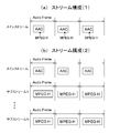
- an audio stream (main stream) including channel encoded data encoded by MPEG4 AAC is generated, and this audio stream is also generated.
- a predetermined number of groups of object encoded data encoded with MPEG-H 3D Audio is embedded in the user data area.
- an audio stream (main stream) including channel encoded data encoded by MPEG4 AAC is generated, and MPEG-H A predetermined number of audio streams (substreams 1 to N) including a predetermined number of groups of object encoded data encoded by 3D Audio are generated.
- the service receiver 200 receives the transport stream TS transmitted from the service transmitter 100 on broadcast waves or net packets.
- the transport stream TS includes a predetermined number of audio streams including channel encoded data and a predetermined number of groups of object encoded data in addition to the video stream.
- the service receiver 200 decodes the video stream to obtain a video output.
- the service receiver 200 If the service receiver 200 supports object encoded data, the service receiver 200 extracts channel encoded data and object encoded data from a predetermined number of audio streams, performs decoding processing, and supports video output. Audio output. On the other hand, if the service receiver 200 does not support the object encoded data, the service receiver 200 extracts only the channel encoded data from the predetermined number of audio streams, performs the decoding process, and outputs the audio output corresponding to the video output. obtain.
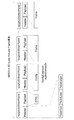
- FIG. 3 shows a configuration example of the stream generation unit 110A included in the service transmitter 100 in that case.
- the stream generation unit 110 includes a video encoder 112, an audio channel encoder 113, an audio object encoder 114, and a TS formatter 115.
- the video encoder 112 receives the video data SV, encodes the video data SV, and generates a video stream.
- the audio object encoder 114 receives the object data constituting the audio data SA, performs MPEG-H 3D Audio encoding on the object data, and generates an audio stream (object encoded data).
- the audio channel encoder 113 inputs channel data constituting the audio data SA, performs MPEG4 AAC encoding on the channel data, generates an audio stream, and generates an audio stream in the user data area by the audio object encoder 114 Embedded audio stream.
- FIG. 4 shows a configuration example of the object encoded data.
- it consists of two encoded object data.
- the two encoded object data are encoded data of an immersive audio object (IAO: Immersive ⁇ ⁇ ⁇ ⁇ ⁇ audio object) and a speech dialog object (SDO: Speech Dialog object).
- IAO Immersive ⁇ ⁇ ⁇ ⁇ ⁇ ⁇ audio object
- SDO Speech Dialog object
- the immersive audio object encoded data is object encoded data for immersive sound.
- Speech dialog object encoded data is object encoded data for speech language.
- the speech dialog object encoded data corresponding to the first language includes encoded sample data SCE2 and metadata EXE_El (Object metadata) 2 for mapping the sampled data to a speaker existing at an arbitrary position and rendering it.
- the speech dialog object encoded data corresponding to the second language includes encoded sample data SCE3, metadata EXE_El (Object metadata) 3 for mapping the sampled data to a speaker located at an arbitrary position, and rendering. It is made up of.
- Object encoded data is distinguished by the concept of group according to type.
- the immersive audio object encoded data is group 1
- the speech dialog object encoded data related to the first language is group 2
- the speech dialog object encoded data related to the second language is group 3. It is said that.
- group 1 and group 2 are bundled into preset group 1
- group 1 and group 3 are bundled into preset group 2.
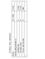
- Fig. 5 shows the correspondence between groups and attributes.
- the group ID (group ID) is an identifier for identifying a group.
- An attribute indicates an attribute of encoded data of each group.
- the switch group ID (switch Group ID) is an identifier for identifying a switching group.
- the reset group ID (preset Group ID) is an identifier for identifying a preset group.
- the stream ID (sub Stream ID) is an identifier for identifying a stream.
- Kind indicates the content type of each group.
- the encoded data belonging to group 1 is object encoded data (immersive audio object encoded data) for immersive sound, and constitutes a switch group and includes channel encoded data. It is embedded in the user data area of the audio stream.
- the encoded data belonging to group 2 is object encoded data (speech dialog object encoded data) for the speech language of the first language, and constitutes switch group 1. It is embedded in the user data area of the audio stream including the channel encoded data.
- the encoded data belonging to group 3 is object encoded data (speech dialog object encoded data) for the speech language of the second language, and constitutes switch group 1. It is embedded in the user data area of the audio stream including the channel encoded data.
- the correspondence shown in the figure indicates that preset group 1 includes group 1 and group 2. Furthermore, the illustrated correspondence relationship shows that the preset group 2 includes a group 1 and a group 3.
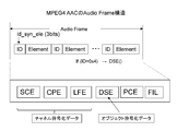
- FIG. 6 shows the structure of an MPEG4 AAC audio frame.
- This audio frame is composed of a plurality of elements.
- At the head of each element (element) is a 3-bit identifier (ID) of “id_syn_ele”, and the element contents can be identified.
- ID 3-bit identifier
- This audio frame includes elements such as SCE (Single Channel Element), CPE (Channel Pair Element), LFE (Low Frequency Element), DSE (Data Stream Element), PCE (Program Config Element), and FIL (Fill Element). included.
- SCE Single Channel Element
- CPE Choannel Pair Element
- LFE Low Frequency Element
- DSE Data Stream Element
- PCE Program Config Element
- FIL Fill Element
- the PCE element is an element including the number of channel elements and a downmix (down_mix) coefficient.
- the FIL element is an element used for defining extension information.
- the element of DSE is an element in which user data can be placed, and “id_syn_ele” of this element is “0x4”. Object encoded data is embedded in this DSE element.
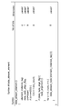
- FIG. 7 shows the configuration (Syntax) of DSE (Data Stream Element ()).
- the 4-bit field of “element_instance_tag” indicates the data type in the DSE, but this value may be set to “0” when the DSE is used as unified user data.
- Data_byte_align_flag is set to “1” so that the entire DSE is byte-aligned.
- the value of “count” or “esc_count” indicating the number of additional bytes is appropriately determined depending on the size of the user data. A maximum of 510 bytes can be counted by “count” and “esc_count”. That is, the data that can be arranged in one DSE element is up to 510 bytes.
- “Metadata ()” is inserted in the field of “data_stream_byte”.
- FIG. 8A shows the structure (Syntax) of “metadata ()”
- FIG. 8B shows the contents (semantics) of main information in the structure.
- the 8-bit field of “metadata_type” indicates the type of metadata. For example, “0x10” indicates object code data in the MPEG-H format (MPEG-H 3D Audio).
- the 8-bit field of “count” indicates the count number in ascending order of metadata in time series.
- the data that can be arranged in one DSE element is up to 510 bytes, but the size of the object encoded data may be larger than 510 bytes.
- a plurality of DSE elements are used, and the count number indicated by “count” indicates the connection relationship of the plurality of DSE elements.
- Object encoded data is arranged in the area of “data_byte”.
- FIG. 9 shows the structure of an audio frame of MPEG-H 3D Audio.
- This audio frame is composed of a plurality of MPEG audio stream packets (mpeg
- Each MPEG audio stream packet is composed of a header and a payload.
- the header has information such as packet type (Packet type), packet label (Packet type Label), and packet length (Packet type Length).
- Information defined by the packet type of the header is arranged in the payload.
- the payload information includes “SYNC” corresponding to the synchronization start code, “Frame” that is actual data, and “Config” indicating the configuration of this “Frame”.
- “Frame” includes object encoded data constituting 3D audio transmission data.
- the channel coded data constituting the 3D audio transmission data is included in the MPEG4 AAC audio frame.
- the object encoded data is composed of encoded sample data of SCE (Single Channel Element) and metadata for rendering it by mapping it to a speaker existing at an arbitrary position (see FIG. 4). This metadata is included as an extension element (Ext_element).
- FIG. 10A shows a packet configuration example of object encoded data.
- one group of object encoded data is included.
- “GroupID [0] 1” information registered in “AudioSceneInfo ()” included in “Config” indicates that “Frame” having the encoded data of group 1 is arranged. . Note that the value of the packet label (PL) is the same for “Config” and each “Frame” corresponding thereto.
- “Frame” having the encoded data of group 1 includes “Frame” including metadata as extension elements (Ext_element) and “Frame” including encoded sample data of SCE (Single Channel Element). It has become.
- FIG. 10B shows another packet configuration example of the object encoded data.
- two groups of object encoded data are included.
- “Frame” having the encoded data of group 2 includes “Frame” including metadata as extension elements (Ext_element) and “Frame” including encoded sample data of SCE (Single Channel Element). It has become.
- “Frame” having group 3 encoded data includes “Frame” including metadata as an extension element (Ext_element) and “Frame” including encoded sample data of SCE (Single Channel Element). It has become.
- the TS formatter 115 converts the video stream output from the video encoder 112 and the audio stream output from the audio channel encoder 113 into PES packets, further transport-packets, and multiplexes them as a multiplexed stream. Transport stream TS is obtained.
- the TS formatter 115 also encodes object coding related to channel coding data included in the audio stream in the user data area of the audio stream under the container layer, in this embodiment, the program map table (PMT). Insert identification information that identifies the presence of data embedding. The TS formatter 115 inserts this identification information into the audio elementary stream loop corresponding to the audio stream using an existing ancillary data descriptor (Ancillary_data_descriptor).
- PMT program map table
- FIG. 11 shows a structural example (Syntax) of an ancillary data descriptor.
- An 8-bit field of “descriptor_tag” indicates a descriptor type.
- an ancillary data descriptor is indicated.
- the 8-bit field of “descriptor_length” indicates the length (size) of the descriptor, and indicates the number of subsequent bytes as the length of the descriptor.
- the 8-bit field of “ancillary_data_identifier” indicates what kind of data is embedded in the user data area of the audio stream. In this case, setting “1” for each bit indicates that the type of data corresponding to that bit is embedded.
- FIG. 12 shows the correspondence between bits and data types in the current state.
- object encoded data (Object data) is newly defined as a data type in bit 7, and by setting “1” in bit 7, object encoded data is stored in the user data area of the audio stream. To identify that there is an embedding.
- the TS formatter 115 inserts attribute information or the like indicating the attributes of a predetermined number of groups of object encoded data under the container layer, in this embodiment, the program map table (PMT).
- the TS formatter 115 inserts this attribute information or the like into the audio elementary stream loop corresponding to the audio stream using a 3D audio stream configuration descriptor (3Daudio_stream_config_descriptor).
- FIG. 13 shows a structural example (Syntax) of the 3D audio stream configuration descriptor.
- FIG. 14 shows the contents (Semantics) of main information in the structural example.
- An 8-bit field of “descriptor_tag” indicates a descriptor type.
- a 3D audio stream config descriptor is indicated.
- the 8-bit field of “descriptor_length” indicates the length (size) of the descriptor, and indicates the number of subsequent bytes as the length of the descriptor.
- the 8-bit field “NumOfGroups, N” indicates the number of groups.
- An 8-bit field of “NumOfPresetGroups, P” indicates the number of preset groups. As many as the number of groups, an 8-bit field of “groupID”, an 8-bit field of “attribute_of_groupID”, an 8-bit field of “SwitchGroupID”, and an 8-bit field of “audio_streamID” are repeated.
- the “groupID” field indicates a group identifier.
- the field of “attribute_of_groupID” indicates an attribute of the object encoded data of the corresponding group.
- the field of “SwitchGroupID” is an identifier indicating which switch group the corresponding group belongs to. “0” indicates that it does not belong to any switch group. Items other than “0” indicate the switch group to which the group belongs.
- the 8-bit field of “contentKind” indicates the content type of the group.
- “Audio_streamID” is an identifier indicating an audio stream including the group.
- FIG. 15 shows content types defined in “contentKind”.
- the 8-bit field of “presetGroupID” and the 8-bit field of “NumOfGroups_in_preset, ⁇ R ” are repeated by the number of preset groups.
- a field of “presetGroupID” is an identifier indicating a bundle in which a group is preset.
- a field of “NumOfGroups_in_preset, R” indicates the number of groups belonging to the preset group. Then, for each preset group, the 8-bit field of “groupID” is repeated for the number of groups belonging to the preset group to indicate the group belonging to the preset group.
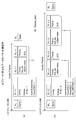
- FIG. 16 shows a configuration example of the transport stream TS.
- PES packet “video PES” of the video stream identified by PID1.
- PES packet “audio ⁇ PES ”of the audio stream identified by PID2.
- the PES packet includes a PES header (PES_header) and a PES payload (PES_payload).
- the PES packet “audio PES” of the audio stream includes MPEG4 AAC channel encoded data, and MPEG-H 3D Audio object encoded data is embedded in the user data area.
- the transport stream TS includes a PMT (Program Map Table) as PSI (Program Specific Information).
- PSI is information describing to which program each elementary stream included in the transport stream belongs.
- the PMT has a program loop (Program ⁇ ⁇ ⁇ loop) that describes information related to the entire program.
- an elementary stream loop having information related to each elementary stream exists in the PMT.
- a video elementary stream loop (video (ES loop) corresponding to the video stream exists
- an audio elementary stream loop (audio ES loop) corresponding to the audio stream exists.
- video elementary stream loop information such as a stream type and PID (packet identifier) is arranged corresponding to the video stream, and a descriptor describing information related to the video stream is also arranged. Is done.
- the value of “Stream_type” of this video stream is set to “0x24”, and the PID information indicates PID1 given to the PES packet “video PES” of the video stream as described above.
- HEVCV descriptor is arranged.
- audio elementary stream loop In the audio elementary stream loop (audio ES loop), information such as a stream type and PID (packet identifier) is arranged corresponding to the audio stream, and a descriptor describing information related to the audio stream is also arranged. Is done. The value of “Stream_type” of this audio stream is set to “0x11”, and the PID information indicates PID2 given to the PES packet “audio PES” of the audio stream as described above.
- ancillary data descriptor and 3D audio stream configuration descriptor are arranged.
- the video data SV is supplied to the video encoder 112.
- the video data SV is encoded, and a video stream including the encoded video data is generated.
- This video stream is supplied to the TS formatter 115.
- the object data constituting the audio data SA is supplied to the audio object encoder 114.
- MPEG-H 3D Audio encoding is performed on the object data to generate an audio stream (object encoded data). This audio stream is supplied to the audio channel encoder 113.
- the channel data constituting the audio data SA is supplied to the audio channel encoder 113.
- the audio channel encoder 113 performs MPEG4 AAC encoding on the channel data to generate an audio stream (channel encoded data).
- the audio channel encoder 113 embeds the audio stream (object encoded data) generated by the audio object encoder 114 in the user data area.
- the video stream generated by the video encoder 112 is supplied to the TS formatter 115.
- the audio stream generated by the audio channel encoder 113 is supplied to the TS formatter 115.
- a stream supplied from each encoder is converted into a PES packet, further converted into a transport packet, and multiplexed to obtain a transport stream TS as a multiplexed stream.
- an ancillary data descriptor is inserted in the audio elementary stream loop. This descriptor includes identification information for identifying that object encoded data is embedded in the user data area of the audio stream.
- a 3D audio stream configuration descriptor is inserted in the audio elementary stream loop.
- This descriptor includes attribute information indicating the attributes of a predetermined number of groups of object encoded data.
- FIG. 17 illustrates a configuration example of the stream generation unit 110B included in the service transmitter 100 in that case.
- the stream generation unit 110B includes a video encoder 122, an audio channel encoder 123, audio object encoders 124-1 to 124-N, and a TS formatter 125.
- the video encoder 122 receives the video data SV, encodes the video data SV, and generates a video stream.
- the audio channel encoder 123 inputs channel data constituting the audio data SA, performs MPEG4 AAC encoding on the channel data, and generates an audio stream (channel encoded data) as a main stream.
- Each of the audio object encoders 124-1 to 124-N inputs object data constituting the audio data SA, performs MPEG-H 3D Audio encoding on the object data, and outputs an audio stream as a substream ( Object encoded data).
- the substream 1 includes an immersive audio object (IAO)
- the substream 2 includes The encoded data of a speech dialog object (SDO: Speech Dialog object) is included.
- IAO immersive audio object
- SDO Speech Dialog object
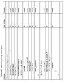
- FIG. 19 shows the correspondence between groups and attributes.
- the group ID (group ID) is an identifier for identifying a group.
- An attribute indicates an attribute of encoded data of each group.
- the switch group ID (switch Group ID) is an identifier for identifying groups that can be switched to each other.
- the preset group ID (preset Group ID) is an identifier for identifying a preset group.
- the stream ID (Stream ID) is an identifier for identifying a stream.
- Kind indicates the content type of each group.
- the encoded data belonging to group 1 is object encoded data for immersive sound (immersive audio object encoded data), and does not constitute a switch group and is included in substream 1. It shows that it is.
- the encoded data belonging to group 2 is object encoded data (speech dialog object encoded data) for the speech language of the first language, and constitutes switch group 1. In other words, it is included in the substream 2.
- the encoded data belonging to group 3 is object encoded data (speech dialog object encoded data) for the speech language of the second language, and constitutes switch group 1. In other words, it is included in the substream 2.
- the correspondence shown in the figure indicates that preset group 1 includes group 1 and group 2. Furthermore, the illustrated correspondence relationship shows that the preset group 2 includes a group 1 and a group 3.
- the TS formatter 125 outputs a video stream output from the video encoder 112, an audio stream output from the audio channel encoder 123, and an audio stream output from the audio object encoders 124-1 to 124-N. Are converted into PES packets, further converted into transport packets, and multiplexed to obtain a transport stream TS as a multiplexed stream.
- the TS formatter 125 includes, under the container layer, in this embodiment, a program map table (PMT), attribute information indicating each attribute of object encoded data of a predetermined number of groups, and a predetermined number of groups of groups. Stream correspondence information indicating which substream each object encoded data is included in is inserted.
- the TS formatter 125 transmits these pieces of information in a 3D audio stream configuration descriptor (3Daudio_stream_config_descriptor) (FIG. 13) in an audio elementary stream loop corresponding to at least one substream of a predetermined number of substreams. To insert.
- a program map table PMT
- attribute information indicating each attribute of object encoded data of a predetermined number of groups
- Stream correspondence information indicating which substream each object encoded data is included in is inserted.
- the TS formatter 125 transmits these pieces of information in a 3D audio stream configuration descriptor (3Daudio_stream_config_descriptor) (FIG. 13) in an audio elementary stream loop
- the TS formatter 125 inserts stream identifier information indicating each stream identifier of a predetermined number of substreams under a container layer, in this embodiment, a program map table (PMT).
- PMT program map table
- the TS formatter 125 inserts this information into an audio elementary stream loop corresponding to each of a predetermined number of substreams using a 3D audio stream ID descriptor (3Daudio_substreamID_descriptor).
- FIG. 20A shows a structural example (Syntax) of a 3D audio stream ID descriptor.
- FIG. 20B shows the contents (Semantics) of main information in the structural example.
- the 8-bit field of “descriptor_tag” indicates the descriptor type. Here, it indicates a 3D audio stream ID descriptor.
- the 8-bit field of “descriptor_length” indicates the length (size) of the descriptor, and indicates the number of subsequent bytes as the length of the descriptor.
- An 8-bit field of “audio_streamID” indicates a substream identifier.
- FIG. 21 shows a configuration example of the transport stream TS.
- PES packet “video PES” of the video stream identified by PID1.
- audio ⁇ PES audio ⁇ PES
- PES_payload PES payload
- DTS and PTS time stamps are inserted in the PES header.
- the PES packet “audio PES” of the audio stream (main stream) identified by PID2 includes MPEG4 AAC channel encoded data.
- the PES packet “audio PES” of the audio stream (substream) identified by PID3 includes MPEG-H 3D Audio object encoded data.
- the transport stream TS includes a PMT (Program Map Table) as PSI (Program Specific Information).
- PSI is information describing to which program each elementary stream included in the transport stream belongs.
- the PMT has a program loop (Program ⁇ ⁇ ⁇ loop) that describes information related to the entire program.
- an elementary stream loop having information related to each elementary stream exists in the PMT.
- video ES loop video elementary stream loop
- audio ES loop audio elementary stream loop
- video elementary stream loop information such as a stream type and PID (packet identifier) is arranged corresponding to the video stream, and a descriptor describing information related to the video stream is also arranged. Is done.
- the value of “Stream_type” of this video stream is set to “0x24”, and the PID information indicates PID1 given to the PES packet “video PES” of the video stream as described above.
- an HEVC descriptor is also arranged.
- audio elementary stream loop (audio
- information such as a stream type and PID (packet identifier)
- PID packet identifier
- a descriptor describing the relevant information is also arranged.
- the value of “Stream_type” of this audio stream is set to “0x11”, and the PID information indicates PID2 assigned to the PES packet “audio PES” of the audio stream (main stream) as described above.
- audio elementary stream loop (audio ES loop) corresponding to the audio stream (substream)
- information such as the stream type and PID (packet identifier) is arranged corresponding to the audio stream, and the audio A descriptor that describes information related to the stream is also arranged.
- the value of “Stream_type” of this audio stream is set to “0x2D”, and the PID information indicates PID3 given to the PES packet “audio PES” of the audio stream (main stream) as described above.
- the descriptor the above-described 3D audio stream configuration descriptor and 3D audio stream ID descriptor are also arranged.
- the video data SV is supplied to the video encoder 122.
- the video data SV is encoded, and a video stream including the encoded video data is generated.
- the channel data constituting the audio data SA is supplied to the audio channel encoder 123.
- MPEG4 AAC encoding is performed on the channel data to generate an audio stream (channel encoded data) as a main stream.
- object data constituting the audio data SA is supplied to the audio object encoders 124-1 to 124-N.
- Each of the audio object encoders 124-1 to 124-N performs MPEG-H 3D Audio encoding on the object data to generate an audio stream (object encoded data) as a substream.
- the video stream generated by the video encoder 122 is supplied to the TS formatter 125.
- the audio stream (main stream) generated by the audio channel encoder 113 is supplied to the TS formatter 125. Further, the audio stream (substream) generated by the audio object encoders 124-1 to 124-N is supplied to the TS formatter 125.
- a stream supplied from each encoder is converted into a PES packet, further converted into a transport packet, and multiplexed to obtain a transport stream TS as a multiplexed stream.
- a 3D audio stream configuration descriptor is inserted in an audio elementary stream loop corresponding to at least one substream of a predetermined number of substreams.
- the 3D audio stream config descriptor indicates attribute information indicating the attributes of a predetermined number of groups of object encoded data and which substream includes the predetermined number of groups of object encoded data. Includes stream correspondence information.
- the 3D audio stream ID descriptor is inserted in the audio elementary stream loop corresponding to each of a predetermined number of substreams in the audio elementary stream loop corresponding to the substream.
- This descriptor includes stream identifier information indicating each stream identifier of a predetermined number of audio streams.
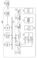
- FIG. 22 shows a configuration example of the service receiver 200.
- the service receiver 200 includes a reception unit 201, a TS analysis unit 202, a video decoder 203, a video processing circuit 204, a panel drive circuit 205, and a display panel 206.
- the service receiver 200 includes multiplexing buffers 211-1 to 211 -M, a combiner 212, a 3D audio decoder 213, an audio output processing circuit 214, and a speaker system 215.
- the service receiver 200 includes a CPU 221, a flash ROM 222, a DRAM 223, an internal bus 224, a remote control receiver 225, and a remote control transmitter 226.
- the CPU 221 controls the operation of each unit of service receiver 200.
- the flash ROM 222 stores control software and data.
- the DRAM 223 constitutes a work area for the CPU 221.
- the CPU 221 develops software and data read from the flash ROM 222 on the DRAM 223 to activate the software, and controls each unit of the service receiver 200.
- the remote control receiving unit 225 receives the remote control signal (remote control code) transmitted from the remote control transmitter 226 and supplies it to the CPU 221.
- the CPU 221 controls each part of the service receiver 200 based on this remote control code.
- the CPU 221, flash ROM 222, and DRAM 223 are connected to the internal bus 224.
- the receiving unit 201 receives the transport stream TS transmitted from the service transmitter 100 on broadcast waves or net packets.
- the transport stream TS has a predetermined number of audio streams in addition to the video stream.
- FIG. 23 shows an example of the received audio stream.
- FIG. 23A shows an example of the stream configuration (1).
- the main stream is identified by PID2.
- FIG. 23B shows an example of the stream configuration (2).
- a main stream including channel encoded data encoded with MPEG4 AAC, and a predetermined number of substreams including a predetermined number of groups of object encoded data encoded with MPEG-H 3D Audio.
- the main stream is identified by PID2, and the substream is identified by PID3.
- the main can be PID3 and the sub can be PID2.
- the TS analyzer 202 extracts a video stream packet from the transport stream TS and sends it to the video decoder 203.
- the video decoder 203 reconstructs a video stream from the video packets extracted by the TS analysis unit 202 and performs a decoding process to obtain uncompressed image data.
- the video processing circuit 204 performs scaling processing, image quality adjustment processing, and the like on the video data obtained by the video decoder 203 to obtain video data for display.
- the panel drive circuit 205 drives the display panel 206 based on the display image data obtained by the video processing circuit 204.
- the display panel 206 includes, for example, an LCD (Liquid Crystal Display), an organic EL display (organic electroluminescence display), and the like.
- the TS analysis unit 202 extracts various information such as descriptor information from the transport stream TS, and sends it to the CPU 221.
- the various information includes information on the ancillary data descriptor (Ancillary_data_descriptor) and 3D audio stream configuration descriptor (3Daudio_stream_config_descriptor) (see FIG. 16). From these descriptor information, the CPU 221 can recognize that the object encoded data is embedded in the user data area of the main stream including the channel encoded data, and recognize the attribute of the object encoded data of each group. To do.
- the various information includes information on the 3D audio stream config descriptor (3Daudio_stream_config_descriptor) and the 3D audio stream ID descriptor (3Daudio_substreamID_descriptor) (see FIG. 21). From these descriptor information, the CPU 221 recognizes the attribute of each group of object encoded data, which substream contains the object encoded data of each group, and the like.
- the TS analysis unit 202 selectively extracts a predetermined number of audio streams included in the transport stream TS with a PID filter under the control of the CPU 221. That is, in the stream configuration (1), the main stream is taken out. On the other hand, in the stream configuration (2), the main stream is extracted and a predetermined number of substreams are extracted.
- Each of the multiplexing buffers 211-1 to 211 -M takes in the audio stream (only the main stream, or the main stream and substream) extracted by the TS analysis unit 202.
- the number M of the multiplexing buffers 211-1 to 211 -M is a necessary and sufficient number, but in actual operation, only the number of audio streams extracted by the TS analysis unit 202 is used.
- the combiner 212 reads out the audio stream for each audio frame from the multiplexing buffer in which the audio streams extracted by the TS analysis unit 202 of the multiplexing buffers 211-1 to 211 -M are captured, and the 3D audio decoder 213. Send to.
- the 3D audio decoder 213 takes out channel encoded data and object encoded data under the control of the CPU 221, performs decoding processing, and obtains audio data for driving each speaker of the speaker system 215.
- channel encoded data is extracted from the main stream
- object encoded data is extracted from the user data area.
- the channel encoded data is extracted from the main stream and the object encoded data is extracted from the substream.
- the 3D audio decoder 213 When the 3D audio decoder 213 decodes the channel encoded data, the 3D audio decoder 213 performs downmix and upmix processing on the speaker configuration of the speaker system 215 as necessary, and obtains audio data for driving each speaker. . Further, when decoding the object encoded data, the 3D audio decoder 213 calculates speaker rendering (mixing ratio to each speaker) based on the object information (metadata), and depending on the calculation result, the audio of the object is calculated. The data is mixed into audio data for driving each speaker.
- the audio output processing circuit 214 performs necessary processing such as D / A conversion and amplification on the audio data for driving each speaker obtained by the 3D audio decoder 213, and supplies it to the speaker system 215.
- the speaker system 215 includes a plurality of speakers such as a plurality of channels, for example, two channels, 5.1 channels, 7.1 channels, 22.2 channels, and the like.
- the receiving unit 201 receives the transport stream TS transmitted from the service transmitter 100 on broadcast waves or net packets.
- the transport stream TS has a predetermined number of audio streams in addition to the video stream.
- a predetermined number of groups of objects encoded with MPEG-H 3D Audio are included in the user data area of the audio stream, which includes channel encoded data encoded with MPEG4 AAC. There is only a main stream in which encoded data is embedded.
- the stream configuration (2) there is a main stream including channel encoded data encoded by MPEG4 AAC as an audio stream, and a predetermined number of groups encoded by MPEG-H 3D Audio. There are a predetermined number of substreams including the object encoded data.
- the TS analysis unit 202 extracts a video stream packet from the transport stream TS and supplies it to the video decoder 203.
- the video decoder 203 a video stream is reconstructed from the video packets extracted by the TS analysis unit 202, decoding processing is performed, and uncompressed video data is obtained. This video data is supplied to the video processing circuit 204.
- the video processing circuit 204 performs scaling processing, image quality adjustment processing, and the like on the video data obtained by the video decoder 203 to obtain video data for display.
- This display video data is supplied to the panel drive circuit 205.
- the panel drive circuit 205 drives the display panel 206 based on the display video data. As a result, an image corresponding to the video data for display is displayed on the display panel 206.
- various information such as descriptor information is extracted from the transport stream TS and sent to the CPU 221.
- the various information includes information on the ancillary data descriptor and the 3D audio stream configuration descriptor (see FIG. 16). From the descriptor information, the CPU 221 recognizes that the object encoded data is embedded in the user data area of the main stream including the channel encoded data, and recognizes the attribute of the object encoded data of each group. Is done.
- the various information includes information on the 3D audio stream configuration descriptor and the 3D audio stream ID descriptor (see FIG. 21). From these descriptor information, the CPU 221 recognizes the attribute of the object encoded data of each group, which substream contains the object encoded data of each group, and the like.
- a predetermined number of audio streams included in the transport stream TS are selectively extracted by the PID filter under the control of the CPU 221. That is, in the case of the stream configuration (1), the main stream is extracted. On the other hand, in the stream configuration (2), the main stream is extracted and a predetermined number of substreams are extracted.
- the audio stream (only the main stream, or the main stream and substream) extracted by the TS analysis unit 202 is acquired.
- the audio stream is read for each audio frame from each multiplexing buffer in which the audio stream has been captured, and is supplied to the 3D audio decoder 213.
- the channel encoded data and the object encoded data are extracted under the control of the CPU 221, subjected to decoding processing, and audio data for driving each speaker of the speaker system 215 is obtained.
- the stream configuration (1) channel encoded data is extracted from the main stream, and object encoded data is extracted from the user data area.
- the stream configuration (2) channel encoded data is extracted from the main stream and object encoded data is extracted from the substream.
- the audio data for driving each speaker obtained by the 3D audio decoder 213 is supplied to the audio output processing circuit 214.
- the audio output processing circuit 214 performs necessary processing such as D / A conversion and amplification on the audio data for driving each speaker.
- the processed audio data is supplied to the speaker system 215. As a result, a sound output corresponding to the display image on the display panel 206 is obtained from the speaker system 215.
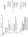
- FIG. 24 schematically shows an audio decoding process in the case of the stream configuration (1).
- a transport stream TS which is a multiplexed stream, is input to the TS analysis unit 202.
- the TS analysis unit 202 analyzes the system layer and supplies descriptor information (ancillary data descriptor and 3D audio stream configuration descriptor information) to the CPU 221.
- the CPU 221 Based on the descriptor information, the CPU 221 recognizes that the object encoded data is embedded in the user data area of the main stream including the channel encoded data, and the attribute of the object encoded data of each group is determined. Be recognized.
- the main stream packet is selectively extracted by the PID filter and is captured by the multiplexing buffer 211 (211-1 to 211-M).
- the audio channel decoder of the 3D audio decoder 213 processing on the main stream taken into the multiplexing buffer 211 is performed. That is, in the audio channel decoder, the DSE in which the object encoded data is arranged is extracted from the main stream and sent to the CPU 221. In the audio channel decoder of the conventional receiver, since this DSE is discarded, compatibility is ensured.
- channel encoded data is taken out from the main stream and subjected to decoding processing to obtain audio data for driving each speaker.
- information on the number of channels is transmitted and received between the audio channel decoder and the CPU 221, and downmix and upmix processing to the speaker configuration of the speaker system 215 is performed as necessary.
- the CPU 221 analyzes the DSE, and sends the object encoded data arranged therein to the audio object decoder of the 3D audio decoder 213.
- object encoded data is decoded, and object metadata and audio data are obtained.
- Audio data for driving each speaker obtained by the audio channel encoder is supplied to the mixing / rendering unit.
- the object metadata and audio data obtained by the audio object decoder are also supplied to the mixing / rendering unit.
- the mixing / rendering unit calculates the mapping of the audio data of the object to the audio output target with respect to the speaker output target based on the metadata of the object, and adds the result of the calculation to the channel data to produce a decoded output.
- FIG. 25 schematically shows an audio decoding process in the case of the stream configuration (2).
- a transport stream TS which is a multiplexed stream, is input to the TS analysis unit 202.
- the TS analysis unit 202 analyzes the system layer, and supplies descriptor information (3D audio stream configuration descriptor and 3D audio stream ID descriptor information) to the CPU 221.
- the CPU 221 Based on the descriptor information, the CPU 221 recognizes the attribute of the object encoded data of each group, the substream in which the object encoded data of each group is included, and the like from the descriptor information.
- the main stream and a predetermined number of substream packets are selectively extracted by the PID filter and are captured by the multiplexing buffer 211 (211-1 to 211-M).
- the substream packet is not extracted by the PID filter, and only the main stream is extracted, so that compatibility is ensured.
- channel encoded data is taken out from the main stream taken into the multiplexing buffer 211 and subjected to decoding processing, thereby obtaining audio data for driving each speaker.
- information on the number of channels is transmitted and received between the audio channel decoder and the CPU 221, and downmix and upmix processing to the speaker configuration of the speaker system 215 is performed as necessary.
- the audio object decoder of the 3D audio decoder 213 extracts a predetermined number of groups of object encoded data required based on user selection or the like from a predetermined number of substreams captured in the multiplexing buffer 211. Then, the decoding process is performed, and the metadata and audio data of the object are obtained.
- Audio data for driving each speaker obtained by the audio channel encoder is supplied to the mixing / rendering unit.
- the object metadata and audio data obtained by the audio object decoder are also supplied to the mixing / rendering unit.
- the mixing / rendering unit calculates the mapping of the audio data of the object to the audio output target with respect to the speaker output target based on the metadata of the object, and adds the result of the calculation to the channel data to produce a decoded output.
- the service transmitter 100 transmits a predetermined number of audio streams having channel encoded data and object encoded data constituting 3D audio transmission data, and this predetermined number
- the audio stream is generated so that the object encoded data is discarded by a receiver that does not support the object encoded data. Therefore, it is possible to provide a new 3D audio service while maintaining compatibility with a conventional audio receiver without impairing the effective use of the transmission band.
- FIG. 26 shows the structure of an AC3 frame (AC3 Synchronization Frame).
- the channel data is encoded so that the total size of “mantissa data” of “Audblock 5”, “AUX”, and “CRC” does not exceed 3/8 of the whole.
- metadata MD is inserted in the area “AUX”.
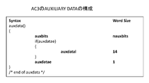
- FIG. 27 shows the structure of AC3 auxiliary data (Auxiliary Data).
- auxdatae When “auxdatae” is “1”, “aux data” is enabled, and data of a size indicated by 14 bits (bit units) of “auxdatal” is defined in “auxbits”. The size of “auxbits” at that time is described in “nauxbits”.
- “metadata ()” shown in FIG. 8A is inserted in the “auxbits” field, and the object encoded data is arranged in the “data_byte” field. .
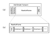
- FIG. 28 (a) shows the structure of the AC4 simple transport layer.
- AC4 is one of the next-generation audio encoding formats of AC3.
- the “RawAc4Frame” field as shown in FIG. 28 (b), there is a TOC (Table Of Content) field at the head, and a predetermined number of substream (Substream) fields thereafter.
- TOC Table Of Content
- a metadata area exists in the substream (ac4_substream_data ()), and a field “umd_payloads_substream ()” is provided therein.
- object encoded data is arranged in the field of “umd_payloads_substream ()”.
- the TOC (ac4_toc ()) includes a field “ac4_presentation_info ()”, and further includes a field “umd_info ()”. Indicates that metadata is inserted in the field of “umd_payloads_substream ()” described above.
- FIG. 30 shows a configuration (syntax) of “umd_info ()”.
- the “umd_version” field indicates the version number of the umd syntax.
- K_id indicates that arbitrary information is containered as “0x6”.
- the combination of the version number and the value of “k_id” is defined as indicating that metadata is inserted in the payload of “umd_payloads_substream ()”.
- FIG. 31 shows a configuration (syntax) of “umd_payloads_substream ()”.
- the 5-bit field of “umd_payload_id” is an ID value indicating that “object_data_byte” is containered, and is a value other than “0”.
- a 16-bit field of “umd_payload_size” indicates the number of bytes after the field.
- An 8-bit field of “userdata_synccode” is a metadata start code and indicates the content of the metadata. For example, “0x10” indicates object code data in the MPEG-H format (MPEG-H 3D Audio). Object encoded data is arranged in the area of “object_data_byte”.
- the encoding method of channel encoded data is MPEG4 AAC
- the encoding method of object encoded data is MPEG-H 3D Audio
- channel encoded data and object encoded data are encoded.
- An example in which the encoding method is different is shown.
- the encoding methods of these two encoded data are the same.
- the encoding method of channel encoded data is AC4, and the encoding method of object encoded data is also AC4.
- the first encoded data is channel encoded data
- the second encoded data related to the first encoded data is object encoded data.
- the combination of the first encoded data and the second encoded data is not limited to this.
- the present technology can be similarly applied to various scalable extensions such as channel number extension and sampling rate extension.
- Example of channel expansion The conventional 5.1 channel encoded data is transmitted as the first encoded data, and the encoded data for the additional channel is transmitted as the second encoded data.
- the conventional decoder decodes only the elements of 5.1 channel, and the decoder corresponding to the additional channel decodes all.
- Extended sampling rate The encoded data of the audio sample data at the conventional audio sampling rate is transmitted as the first encoded data, and the encoded data of the audio sample data having a higher sampling rate is transmitted as the second encoded data.
- the conventional decoder decodes only the conventional sampling rate data, and the decoder corresponding to the high sampling rate decodes all.
- the container is a transport stream (MPEG-2 TS)
- MPEG-2 TS transport stream
- the present technology can be similarly applied to a system distributed in a container of MP4 or other formats.
- MMT MPEG-Media-Transport
- the first encoded data is channel encoded data and the second encoded data is object encoded data has been described.
- the second encoded data may be other channel encoded data, or object encoded data and channel encoded data.
- this technique can also take the following structures.
- an encoding unit that generates a predetermined number of audio streams having first encoded data and second encoded data related to the first encoded data;
- a transmission unit configured to transmit a container of a predetermined format including the generated predetermined number of audio streams;
- the encoding unit generates the predetermined number of audio streams such that the second encoded data is discarded by a receiver that does not correspond to the second encoded data.
- the transmission apparatus according to (3), wherein the encoding method of the first encoded data is MPEG4 AAC, and the encoding method of the second encoded data is MPEG-H 3D Audio.
- the encoding unit The transmission device according to any one of (1) to (4), wherein an audio stream having the first encoded data is generated and the second encoded data is embedded in a user data area of the audio stream. (6) Embedding of the second encoded data related to the first encoded data in the user data area of the audio stream having the first encoded data included in the container in the container layer.
- the transmission device according to (5), further including an information insertion unit that inserts identification information for identifying the presence.
- the first encoded data is channel encoded data
- the second encoded data is object encoded data
- a predetermined number of groups of object encoded data are embedded in the user data area of the audio stream
- the transmission device according to (5) or (6), further including an information insertion unit that inserts attribute information indicating each attribute of the object encoded data of the predetermined number of groups in the layer of the container.
- the encoding unit The first audio stream including the first encoded data is generated, and a predetermined number of second audio streams including the second encoded data are generated. Any one of (1) to (4) The transmitting device according to 1.
- the predetermined number of second audio streams includes a predetermined number of groups of object encoded data
- the transmission device according to (8) further including an information insertion unit that inserts attribute information indicating attributes of the predetermined number of groups of object encoded data in the layer of the container.
- the information insertion unit The transmission apparatus according to (9), further including stream correspondence relationship information indicating which second audio stream each of the predetermined number of groups of object encoded data is included in the container layer.
- the stream correspondence information is The information indicating a correspondence relationship between a group identifier for identifying each of the predetermined number of groups of object encoded data and a stream identifier for identifying each of the predetermined number of second audio streams. Transmitter device.
- the information insertion unit The transmission apparatus according to (11), wherein stream identifier information indicating stream identifiers of the predetermined number of second audio streams is further inserted into the container layer.
- the predetermined number of audio streams are generated so that the second encoded data is discarded by a receiver that does not support the second encoded data.
- a reception unit that receives a container of a predetermined format including a predetermined number of audio streams having first encoded data and second encoded data related to the first encoded data, The predetermined number of audio streams are generated such that the second encoded data is discarded by a receiver that does not correspond to the second encoded data;
- a receiving apparatus further comprising: a processing unit that extracts and processes the first encoded data and the second encoded data from the predetermined number of audio streams included in the container.
- the first encoded data encoding method is different from the second encoded data encoding method.
- the reception apparatus according to (14) or (15), wherein the first encoded data is channel encoded data, and the second encoded data is object encoded data.
- the container includes the audio data in which the first encoded data is included and the second encoded data is embedded in a user data area. (14) to (16) The receiving apparatus in any one. (18) The container includes a first audio stream including the first encoded data and a predetermined number of second audio streams including the second encoded data. The receiving device according to any one of (16). (19) The reception unit includes a reception step of receiving a container of a predetermined format including a predetermined number of audio streams having the first encoded data and the second encoded data related to the first encoded data.
- a receiving method comprising: processing steps of extracting and processing the first encoded data and the second encoded data from the predetermined number of audio streams included in the container.
- the main feature of the present technology is that an audio stream including channel encoded data and having object encoded data embedded in the user data area is transmitted, or object encoded data together with an audio stream including channel encoded data.
Landscapes
- Engineering & Computer Science (AREA)
- Physics & Mathematics (AREA)
- Acoustics & Sound (AREA)
- Signal Processing (AREA)
- Multimedia (AREA)
- Audiology, Speech & Language Pathology (AREA)
- Computational Linguistics (AREA)
- Human Computer Interaction (AREA)
- Health & Medical Sciences (AREA)
- Mathematical Physics (AREA)
- Spectroscopy & Molecular Physics (AREA)
- Two-Way Televisions, Distribution Of Moving Picture Or The Like (AREA)
- Time-Division Multiplex Systems (AREA)
- Reduction Or Emphasis Of Bandwidth Of Signals (AREA)
- Stereo-Broadcasting Methods (AREA)
- Compression, Expansion, Code Conversion, And Decoders (AREA)
- Compression Or Coding Systems Of Tv Signals (AREA)
- Television Systems (AREA)
Abstract
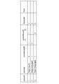
Priority Applications (8)
| Application Number | Priority Date | Filing Date | Title |
|---|---|---|---|
| RU2017111691A RU2700405C2 (ru) | 2014-10-16 | 2015-10-13 | Устройство передачи данных, способ передачи данных, приёмное устройство и способ приёма |
| EP15850900.0A EP3208801A4 (fr) | 2014-10-16 | 2015-10-13 | Dispositif d'émission, procédé d'émission, dispositif de réception et procédé de réception |
| JP2016554075A JP6729382B2 (ja) | 2014-10-16 | 2015-10-13 | 送信装置、送信方法、受信装置および受信方法 |
| CN201580054678.0A CN106796797B (zh) | 2014-10-16 | 2015-10-13 | 发送设备、发送方法、接收设备和接收方法 |
| KR1020177006867A KR20170070004A (ko) | 2014-10-16 | 2015-10-13 | 송신 장치, 송신 방법, 수신 장치 및 수신 방법 |
| MX2017004602A MX368685B (es) | 2014-10-16 | 2015-10-13 | Dispositivo de transmisión, método de transmisión, dispositivo de recepción, y método de recepción. |
| CA2963771A CA2963771A1 (fr) | 2014-10-16 | 2015-10-13 | Dispositif d'emission, methode d'emission, dispositif de reception et methode de reception |
| US15/505,622 US10142757B2 (en) | 2014-10-16 | 2015-10-13 | Transmission device, transmission method, reception device, and reception method |
Applications Claiming Priority (2)
| Application Number | Priority Date | Filing Date | Title |
|---|---|---|---|
| JP2014212116 | 2014-10-16 | ||
| JP2014-212116 | 2014-10-16 |
Publications (1)
| Publication Number | Publication Date |
|---|---|
| WO2016060101A1 true WO2016060101A1 (fr) | 2016-04-21 |
Family
ID=55746647
Family Applications (1)
| Application Number | Title | Priority Date | Filing Date |
|---|---|---|---|
| PCT/JP2015/078875 WO2016060101A1 (fr) | 2014-10-16 | 2015-10-13 | Dispositif d'émission, procédé d'émission, dispositif de réception et procédé de réception |
Country Status (9)
| Country | Link |
|---|---|
| US (1) | US10142757B2 (fr) |
| EP (1) | EP3208801A4 (fr) |
| JP (1) | JP6729382B2 (fr) |
| KR (1) | KR20170070004A (fr) |
| CN (1) | CN106796797B (fr) |
| CA (1) | CA2963771A1 (fr) |
| MX (1) | MX368685B (fr) |
| RU (1) | RU2700405C2 (fr) |
| WO (1) | WO2016060101A1 (fr) |
Cited By (6)
| Publication number | Priority date | Publication date | Assignee | Title |
|---|---|---|---|---|
| WO2019069710A1 (fr) * | 2017-10-05 | 2019-04-11 | ソニー株式会社 | Dispositif et procédé de codage, dispositif et procédé de décodage et programme |
| JP2019533404A (ja) * | 2016-09-23 | 2019-11-14 | ガウディオ・ラボ・インコーポレイテッド | バイノーラルオーディオ信号処理方法及び装置 |
| JP2020502832A (ja) * | 2016-08-01 | 2020-01-23 | ソニー・インタラクティブエンタテインメント エルエルシー | データストリーミングの前方誤り訂正 |
| JP2021515448A (ja) * | 2018-02-22 | 2021-06-17 | ドルビー・インターナショナル・アーベー | パケット化メディアストリームのサイドロード処理のための方法、機器、およびシステム |
| JP2022546923A (ja) * | 2019-08-15 | 2022-11-10 | ドルビー・インターナショナル・アーベー | 変更オーディオビットストリームの生成及び処理のための方法及び装置 |
| JP2023516303A (ja) * | 2020-02-28 | 2023-04-19 | ノキア テクノロジーズ オサケユイチア | オーディオ表現および関連するレンダリング |
Families Citing this family (7)
| Publication number | Priority date | Publication date | Assignee | Title |
|---|---|---|---|---|
| RU2701060C2 (ru) | 2014-09-30 | 2019-09-24 | Сони Корпорейшн | Передающее устройство, способ передачи, приемное устройство и способ приема |
| EP3258467B1 (fr) * | 2015-02-10 | 2019-09-18 | Sony Corporation | Transmission et réception de flux audio |
| US10341036B2 (en) * | 2015-02-10 | 2019-07-02 | Lg Electronics Inc. | Broadcast signal transmission apparatus, broadcast signal reception apparatus, broadcast signal transmission method, and broadcast signal reception method |
| US10719100B2 (en) | 2017-11-21 | 2020-07-21 | Western Digital Technologies, Inc. | System and method for time stamp synchronization |
| US10727965B2 (en) * | 2017-11-21 | 2020-07-28 | Western Digital Technologies, Inc. | System and method for time stamp synchronization |
| KR20200141438A (ko) | 2018-04-11 | 2020-12-18 | 돌비 인터네셔널 에이비 | 6DoF 오디오 렌더링을 위한 방법, 장치 및 시스템, 및 6DoF 오디오 렌더링을 위한 데이터 표현 및 비트스트림 구조 |
| CN108986829B (zh) * | 2018-09-04 | 2020-12-15 | 北京猿力未来科技有限公司 | 数据发送方法、装置、设备及存储介质 |
Citations (3)
| Publication number | Priority date | Publication date | Assignee | Title |
|---|---|---|---|---|
| JP2006139827A (ja) * | 2004-11-10 | 2006-06-01 | Victor Co Of Japan Ltd | 3次元音場情報記録装置及びプログラム |
| JP2011528446A (ja) * | 2008-07-15 | 2011-11-17 | エルジー エレクトロニクス インコーポレイティド | オーディオ信号の処理方法及び装置 |
| JP2012033243A (ja) * | 2010-08-02 | 2012-02-16 | Sony Corp | データ生成装置およびデータ生成方法、データ処理装置およびデータ処理方法 |
Family Cites Families (9)
| Publication number | Priority date | Publication date | Assignee | Title |
|---|---|---|---|---|
| JP4286410B2 (ja) * | 1999-11-18 | 2009-07-01 | パナソニック株式会社 | 記録再生装置 |
| EP2146342A1 (fr) * | 2008-07-15 | 2010-01-20 | LG Electronics Inc. | Procédé et appareil de traitement de signal audio |
| EP2154911A1 (fr) * | 2008-08-13 | 2010-02-17 | Fraunhofer-Gesellschaft zur Förderung der angewandten Forschung e.V. | Appareil pour déterminer un signal audio multi-canal de sortie spatiale |
| JP5771002B2 (ja) * | 2010-12-22 | 2015-08-26 | 株式会社東芝 | 音声認識装置、音声認識方法および音声認識装置を搭載したテレビ受像機 |
| EP3913931B1 (fr) | 2011-07-01 | 2022-09-21 | Dolby Laboratories Licensing Corp. | Appareil de restitution audio, procede et moyens de stockage associes. |
| KR102172279B1 (ko) * | 2011-11-14 | 2020-10-30 | 한국전자통신연구원 | 스케일러블 다채널 오디오 신호를 지원하는 부호화 장치 및 복호화 장치, 상기 장치가 수행하는 방법 |
| US9473870B2 (en) * | 2012-07-16 | 2016-10-18 | Qualcomm Incorporated | Loudspeaker position compensation with 3D-audio hierarchical coding |
| WO2014187990A1 (fr) * | 2013-05-24 | 2014-11-27 | Dolby International Ab | Codage efficace de scènes audio comprenant des objets audio |
| WO2015150384A1 (fr) * | 2014-04-01 | 2015-10-08 | Dolby International Ab | Codage efficace de scènes audio comprenant des objets audio |
-
2015
- 2015-10-13 JP JP2016554075A patent/JP6729382B2/ja active Active
- 2015-10-13 WO PCT/JP2015/078875 patent/WO2016060101A1/fr active Application Filing
- 2015-10-13 US US15/505,622 patent/US10142757B2/en active Active
- 2015-10-13 RU RU2017111691A patent/RU2700405C2/ru active
- 2015-10-13 CA CA2963771A patent/CA2963771A1/fr not_active Abandoned
- 2015-10-13 EP EP15850900.0A patent/EP3208801A4/fr not_active Ceased
- 2015-10-13 MX MX2017004602A patent/MX368685B/es active IP Right Grant
- 2015-10-13 CN CN201580054678.0A patent/CN106796797B/zh active Active
- 2015-10-13 KR KR1020177006867A patent/KR20170070004A/ko not_active Application Discontinuation
Patent Citations (3)
| Publication number | Priority date | Publication date | Assignee | Title |
|---|---|---|---|---|
| JP2006139827A (ja) * | 2004-11-10 | 2006-06-01 | Victor Co Of Japan Ltd | 3次元音場情報記録装置及びプログラム |
| JP2011528446A (ja) * | 2008-07-15 | 2011-11-17 | エルジー エレクトロニクス インコーポレイティド | オーディオ信号の処理方法及び装置 |
| JP2012033243A (ja) * | 2010-08-02 | 2012-02-16 | Sony Corp | データ生成装置およびデータ生成方法、データ処理装置およびデータ処理方法 |
Non-Patent Citations (2)
| Title |
|---|
| JURGEN HERRE ET AL.: "MPEG Spatial Audio Object Coding - The ISO/MPEG Standard for Efficient Coding of Interactive Audio Scenes", JOURNAL OF THE AUDIO ENGINEERING SOCIETY, vol. 60, no. 9, pages 655 - 673, XP009502122 * |
| See also references of EP3208801A4 * |
Cited By (15)
| Publication number | Priority date | Publication date | Assignee | Title |
|---|---|---|---|---|
| US10979175B2 (en) | 2016-08-01 | 2021-04-13 | Sony Interactive Entertainment LLC | Forward error correction for streaming data |
| JP2020502832A (ja) * | 2016-08-01 | 2020-01-23 | ソニー・インタラクティブエンタテインメント エルエルシー | データストリーミングの前方誤り訂正 |
| US11489621B2 (en) | 2016-08-01 | 2022-11-01 | Sony Interactive Entertainment LLC | Forward error correction for streaming data |
| JP2019533404A (ja) * | 2016-09-23 | 2019-11-14 | ガウディオ・ラボ・インコーポレイテッド | バイノーラルオーディオ信号処理方法及び装置 |
| JPWO2019069710A1 (ja) * | 2017-10-05 | 2020-11-05 | ソニー株式会社 | 符号化装置および方法、復号装置および方法、並びにプログラム |
| WO2019069710A1 (fr) * | 2017-10-05 | 2019-04-11 | ソニー株式会社 | Dispositif et procédé de codage, dispositif et procédé de décodage et programme |
| US11595056B2 (en) | 2017-10-05 | 2023-02-28 | Sony Corporation | Encoding device and method, decoding device and method, and program |
| JP7358986B2 (ja) | 2017-10-05 | 2023-10-11 | ソニーグループ株式会社 | 復号装置および方法、並びにプログラム |
| JP2021515448A (ja) * | 2018-02-22 | 2021-06-17 | ドルビー・インターナショナル・アーベー | パケット化メディアストリームのサイドロード処理のための方法、機器、およびシステム |
| JP7274492B2 (ja) | 2018-02-22 | 2023-05-16 | ドルビー・インターナショナル・アーベー | パケット化メディアストリームのサイドロード処理のための方法、機器、およびシステム |
| JP7553188B2 (ja) | 2018-02-22 | 2024-09-18 | ドルビー・インターナショナル・アーベー | パケット化メディアストリームのサイドロード処理のための方法、機器、およびシステム |
| JP2022546923A (ja) * | 2019-08-15 | 2022-11-10 | ドルビー・インターナショナル・アーベー | 変更オーディオビットストリームの生成及び処理のための方法及び装置 |
| JP7314398B2 (ja) | 2019-08-15 | 2023-07-25 | ドルビー・インターナショナル・アーベー | 変更オーディオビットストリームの生成及び処理のための方法及び装置 |
| US11967330B2 (en) | 2019-08-15 | 2024-04-23 | Dolby International Ab | Methods and devices for generation and processing of modified audio bitstreams |
| JP2023516303A (ja) * | 2020-02-28 | 2023-04-19 | ノキア テクノロジーズ オサケユイチア | オーディオ表現および関連するレンダリング |
Also Published As
| Publication number | Publication date |
|---|---|
| KR20170070004A (ko) | 2017-06-21 |
| US10142757B2 (en) | 2018-11-27 |
| MX368685B (es) | 2019-10-11 |
| CN106796797A (zh) | 2017-05-31 |
| RU2017111691A (ru) | 2018-10-08 |
| CN106796797B (zh) | 2021-04-16 |
| JPWO2016060101A1 (ja) | 2017-07-27 |
| MX2017004602A (es) | 2017-07-10 |
| JP6729382B2 (ja) | 2020-07-22 |
| CA2963771A1 (fr) | 2016-04-21 |
| RU2700405C2 (ru) | 2019-09-16 |
| EP3208801A1 (fr) | 2017-08-23 |
| RU2017111691A3 (fr) | 2019-04-18 |
| US20170289720A1 (en) | 2017-10-05 |
| EP3208801A4 (fr) | 2018-03-28 |
Similar Documents
| Publication | Publication Date | Title |
|---|---|---|
| WO2016060101A1 (fr) | Dispositif d'émission, procédé d'émission, dispositif de réception et procédé de réception | |
| JP7529013B2 (ja) | 送信装置および送信方法 | |
| JP7238925B2 (ja) | 送信装置、送信方法、受信装置および受信方法 | |
| JP7310849B2 (ja) | 受信装置および受信方法 | |
| JP7218772B2 (ja) | 受信装置および受信方法 |
Legal Events
| Date | Code | Title | Description |
|---|---|---|---|
| 121 | Ep: the epo has been informed by wipo that ep was designated in this application |
Ref document number: 15850900 Country of ref document: EP Kind code of ref document: A1 |
|
| ENP | Entry into the national phase |
Ref document number: 2016554075 Country of ref document: JP Kind code of ref document: A |
|
| WWE | Wipo information: entry into national phase |
Ref document number: 15505622 Country of ref document: US |
|
| ENP | Entry into the national phase |
Ref document number: 20177006867 Country of ref document: KR Kind code of ref document: A |
|
| ENP | Entry into the national phase |
Ref document number: 2963771 Country of ref document: CA |
|
| REEP | Request for entry into the european phase |
Ref document number: 2015850900 Country of ref document: EP |
|
| WWE | Wipo information: entry into national phase |
Ref document number: 2015850900 Country of ref document: EP |
|
| ENP | Entry into the national phase |
Ref document number: 2017111691 Country of ref document: RU Kind code of ref document: A |
|
| WWE | Wipo information: entry into national phase |
Ref document number: MX/A/2017/004602 Country of ref document: MX |
|
| NENP | Non-entry into the national phase |
Ref country code: DE |