WO2016052885A1 - Humidificateur à stérilisation utilisant des rayons ultraviolets - Google Patents
Humidificateur à stérilisation utilisant des rayons ultraviolets Download PDFInfo
- Publication number
- WO2016052885A1 WO2016052885A1 PCT/KR2015/009668 KR2015009668W WO2016052885A1 WO 2016052885 A1 WO2016052885 A1 WO 2016052885A1 KR 2015009668 W KR2015009668 W KR 2015009668W WO 2016052885 A1 WO2016052885 A1 WO 2016052885A1
- Authority
- WO
- WIPO (PCT)
- Prior art keywords
- unit
- liquid
- storage
- coupled
- sterilizing humidifier
- Prior art date
Links
Images


Classifications
-
- F—MECHANICAL ENGINEERING; LIGHTING; HEATING; WEAPONS; BLASTING
- F24—HEATING; RANGES; VENTILATING
- F24F—AIR-CONDITIONING; AIR-HUMIDIFICATION; VENTILATION; USE OF AIR CURRENTS FOR SCREENING
- F24F8/00—Treatment, e.g. purification, of air supplied to human living or working spaces otherwise than by heating, cooling, humidifying or drying
- F24F8/20—Treatment, e.g. purification, of air supplied to human living or working spaces otherwise than by heating, cooling, humidifying or drying by sterilisation
- F24F8/22—Treatment, e.g. purification, of air supplied to human living or working spaces otherwise than by heating, cooling, humidifying or drying by sterilisation using UV light
-
- F—MECHANICAL ENGINEERING; LIGHTING; HEATING; WEAPONS; BLASTING
- F24—HEATING; RANGES; VENTILATING
- F24F—AIR-CONDITIONING; AIR-HUMIDIFICATION; VENTILATION; USE OF AIR CURRENTS FOR SCREENING
- F24F6/00—Air-humidification, e.g. cooling by humidification
-
- F—MECHANICAL ENGINEERING; LIGHTING; HEATING; WEAPONS; BLASTING
- F24—HEATING; RANGES; VENTILATING
- F24F—AIR-CONDITIONING; AIR-HUMIDIFICATION; VENTILATION; USE OF AIR CURRENTS FOR SCREENING
- F24F13/00—Details common to, or for air-conditioning, air-humidification, ventilation or use of air currents for screening
- F24F13/20—Casings or covers
-
- F—MECHANICAL ENGINEERING; LIGHTING; HEATING; WEAPONS; BLASTING
- F24—HEATING; RANGES; VENTILATING
- F24F—AIR-CONDITIONING; AIR-HUMIDIFICATION; VENTILATION; USE OF AIR CURRENTS FOR SCREENING
- F24F13/00—Details common to, or for air-conditioning, air-humidification, ventilation or use of air currents for screening
- F24F13/28—Arrangement or mounting of filters
-
- F—MECHANICAL ENGINEERING; LIGHTING; HEATING; WEAPONS; BLASTING
- F24—HEATING; RANGES; VENTILATING
- F24F—AIR-CONDITIONING; AIR-HUMIDIFICATION; VENTILATION; USE OF AIR CURRENTS FOR SCREENING
- F24F8/00—Treatment, e.g. purification, of air supplied to human living or working spaces otherwise than by heating, cooling, humidifying or drying
- F24F8/10—Treatment, e.g. purification, of air supplied to human living or working spaces otherwise than by heating, cooling, humidifying or drying by separation, e.g. by filtering
- F24F8/15—Treatment, e.g. purification, of air supplied to human living or working spaces otherwise than by heating, cooling, humidifying or drying by separation, e.g. by filtering by chemical means
- F24F8/167—Treatment, e.g. purification, of air supplied to human living or working spaces otherwise than by heating, cooling, humidifying or drying by separation, e.g. by filtering by chemical means using catalytic reactions
-
- F—MECHANICAL ENGINEERING; LIGHTING; HEATING; WEAPONS; BLASTING
- F24—HEATING; RANGES; VENTILATING
- F24F—AIR-CONDITIONING; AIR-HUMIDIFICATION; VENTILATION; USE OF AIR CURRENTS FOR SCREENING
- F24F6/00—Air-humidification, e.g. cooling by humidification
- F24F2006/006—Air-humidification, e.g. cooling by humidification with water treatment
-
- F—MECHANICAL ENGINEERING; LIGHTING; HEATING; WEAPONS; BLASTING
- F24—HEATING; RANGES; VENTILATING
- F24F—AIR-CONDITIONING; AIR-HUMIDIFICATION; VENTILATION; USE OF AIR CURRENTS FOR SCREENING
- F24F6/00—Air-humidification, e.g. cooling by humidification
- F24F2006/008—Air-humidifier with water reservoir
Definitions
- Exemplary embodiments of the present disclosure relate to a sterilizing humidifier using ultraviolet rays, and more particularly, to a sterilizing humidifier using ultraviolet rays which can perform humidification using liquid sterilized by ultraviolet rays and air from which contaminants and malodorous substances are removed.
- a humidifier is a device which atomizes water and discharges it out of the device in a form of fine water particles to control the humidity in a room.
- a dry season such as late autumn, the winter or early spring which is dry due to a small amount of rainfall, it is easy to catch viral diseases, e.g., cold or influenza, because of low humidity.
- viral diseases e.g., cold or influenza
- Humidifiers are classified according to the kind thereof into a heating humidifier, which heats water and thus generates vapor and mixes it with the air, and an ultrasonic humidifier, which vibrates water using ultrasonic waves to create water particles of a molecular state and discharges the water particles into the air.
- Heating humidifiers heat water contained in a humidification water tank to generate vapor and then spray generated vapor.
- a heater or electrode rod is used to heat water contained in the humidification water tank and generate vapor.
- the heating humidifiers humidify the air using vapor generated in the above-mentioned manner. Therefore, in such heating humidifiers, the humidification rate is comparatively low. Even though water contained in the humidification water tank is heated, the sterilization effect is unsatisfactory because the temperature to which the water is heated is lower than a temperature required to sterilize the water.
- Ultrasonic humidifiers vibrate water using a vibrator to create water particles of a molecular state and then discharge, for humidification, the water particles along with air which is drawn into a humidifier and discharged out of it by a blower fan.
- Ultrasonic humidifiers can humidify a room without heating water.
- the ambient temperature is reduced by the heat of vaporization.
- bacteria contained in water are discharged along with water into the room without sterilization, whereby viral diseases may be caused.
- An embodiment of the present disclosure relates to a sterilizing humidifier using ultraviolet rays which sterilizes water using ultraviolet rays, thus preventing the human body from being damaged by bacteria, and which removes contaminants from the air, thus providing pleasure humidification environment.
- a sterilizing humidifier using ultraviolet rays including: a cover unit in which an air inlet hole and an air outlet hole are formed; a fan unit disposed between the air inlet hole and the air outlet hole and moving air from the air inlet hole toward the air outlet hole; a storage unit coupled to the cover unit and containing liquid therein; a light emitting diode unit installed in the storage unit and radiating ultraviolet rays onto the liquid; and a liquid moving unit for moving the liquid contained in the storage unit to a space between the air outlet hole and the fan unit.
- the present disclosure sterilizes, using ultraviolet rays, liquid such as water contained in a storage unit and uses the sterilized liquid for humidification, thus preventing bacterial infection.
- a functional filter such as a photocatalytic filter, a carbon filter or the like is used to remove contaminants and odor, thus reducing pollution of indoor air.
- FIG. 1 is a schematic perspective view illustrating a sterilizing humidifier using ultraviolet rays in accordance with a first embodiment of the present disclosure.
- FIG. 2 is a view illustrating the configuration of the sterilizing humidifier using ultraviolet rays in accordance with the first embodiment of the present disclosure.
- FIG. 3 is a perspective sectional view of the sterilizing humidifier using ultraviolet rays in accordance with the first embodiment of the present disclosure.
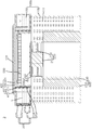
- FIG. 4 is a sectional view of the sterilizing humidifier using ultraviolet rays in accordance with the first embodiment of the present disclosure.
- FIG. 5 is a schematic perspective view illustrating a sterilizing humidifier using ultraviolet rays in accordance with a second embodiment of the present disclosure.
- FIG. 6 is a view illustrating the configuration of the sterilizing humidifier using ultraviolet rays in accordance with the second embodiment of the present disclosure.
- FIG. 7 is a perspective sectional view of the sterilizing humidifier using ultraviolet rays in accordance with the second embodiment of the present disclosure.
- FIG. 8 is a sectional view of the sterilizing humidifier using ultraviolet rays in accordance with the second embodiment of the present disclosure.
- FIG. 9 is a schematic perspective view illustrating a sterilizing humidifier using ultraviolet rays in accordance with a third embodiment of the present disclosure.
- FIG. 10 is a view illustrating the configuration of the sterilizing humidifier using ultraviolet rays in accordance with the third embodiment of the present disclosure.
- FIG. 11 is a perspective sectional view of the sterilizing humidifier using ultraviolet rays in accordance with the third embodiment of the present disclosure.
- FIG. 12 is a sectional view of the sterilizing humidifier using ultraviolet rays in accordance with the third embodiment of the present disclosure.
- an element when referred to as being 'over' or 'under' another element, it may indicate that the former element is directly positioned 'over' or 'under' the latter element or an additional element is interposed therebetween.
- the terms such as 'upper' and 'lower' are the relative concept set from the viewpoint of an observer. Thus, when the viewpoint of the observer is changed, 'upper' may indicate 'lower, and 'lower' may indicate 'upper'.
- FIG. 1 is a schematic perspective view illustrating a sterilizing humidifier using ultraviolet rays in accordance with a first embodiment of the present disclosure.
- FIG. 2 is a view illustrating the configuration of the sterilizing humidifier using ultraviolet rays in accordance with the first embodiment of the present disclosure.
- FIG. 3 is a perspective sectional view of the sterilizing humidifier using ultraviolet rays in accordance with the first embodiment of the present disclosure.
- the sterilizing humidifier 1 using ultraviolet rays in accordance with the first embodiment includes a cover unit 100, a fan unit 200, a storage unit 300 and a liquid moving unit 400.
- the cover unit 100 includes a lower cover 110 and an upper cover 130 which respectively have the air inlet hole 111 and the air outlet hole 131 so as to enable air to flow into and out of the cover unit 100.
- the lower cover 110 is coupled to a lower side of the storage unit 300 and has the air inlet hole 111 therein.
- the lower cover 110 is coupled to the storage unit 300 by a method such as force fitting, bolting or the like.
- a plurality of air inlet holes 111 are formed in the lower cover 110 to allow inflow of air and prevent inflow of coarse dust and so forth.
- the diameter, shape and number of air inlet holes 111 may be changed depending on installation environment of the humidifier, specifications of the fan unit and so forth.
- the upper cover 130 is disposed at a position spaced apart from the lower cover 110 and has the air outlet hole 131 therein.
- the upper cover 130 is coupled to an upper side of the storage unit 300 by a method such as force fitting, bolting or the like.
- a plurality of air outlet holes 131 are formed in the upper cover 130 so that air drawn into the sterilizing humidifier 1 can be discharged to the outside through the air outlet holes 131.
- the upper cover 130 is illustrated as having an approximately circular plate shape and covering the storage unit 300 in the present disclosure, the shape of the upper cover 130 may be changed depending on the shape, etc. of the storage unit 300.
- the fan unit 200 is disposed between the air inlet holes 111 and the air outlet holes 131 and moves air from the air inlet holes 111 to the air outlet holes 131.
- the fan unit 200 includes a rotating motor 210 which is operated by power applied from the outside so as to generate rotational force, and a rotating fan 230 which is rotated by the rotational force of the rotating motor 210 to move air from the air inlet holes 111 to the air outlet holes 131.
- the storage unit 300 is coupled to the cover unit 100.
- Liquid L e.g., water
- a light emitting diode unit 330 may be installed in the storage unit 300.
- the light emitting diode unit 330 radiates ultraviolet rays onto the liquid L to sterilize it.
- Ultraviolet rays are classified into UV-A, UV-B and UV-C rays according to a wavelength.
- Ultraviolet rays radiated from the light emitting diode 333 onto the liquid L refers to UV-C rays for sterilizing the liquid L.
- the storage unit 300 includes a storage member 310 and a light emitting diode unit 330.
- Liquid L is contained in the storage member 310.
- the light emitting diode 333 is removably coupled to the storage member 310.
- the storage member 310 includes an outer storage wall 311, an inner storage wall 315 and a storage bottom 319.
- the outer storage wall 311 forms the appearance of the storage member 310.
- the light emitting diode unit 330 is removably coupled to the outer storage wall 311.
- the outer storage wall 311 includes an outer wall body 312 and a diode mounting part 314.
- the outer wall body 312 is connected at a lower end thereof to the storage bottom 319 and disposed at a position spaced apart from the inner storage wall 315.
- the outer wall body 312 has a cylindrical shape and is made of material including synthetic resin.
- the diode mounting part 314 is coupled to an inner side of the outer wall body 312.
- the light emitting diode 333 is removably coupled to the diode mounting part 314.
- the diode mounting part 314 comprises a plurality of diode mounting parts 314 arranged in a circumferential direction on the outer wall body 312. Each diode mounting part 314 has a recessed shape so that the light emitting diode 333 can be inserted downward into the diode mounting part 314.
- the inner storage wall 315 is spaced apart from the outer storage wall 311 and disposed inside the outer storage wall 311.
- the liquid moving unit 400 is coupled to the inner storage wall 315.
- the inner storage wall 315 has an approximately cylindrical shape.
- the fan unit 200 is disposed inside the inner storage wall 315.
- a liquid moving body 411 is disposed on an outer side of the inner storage wall 315.
- the storage bottom 319 connects a lower end of the outer storage wall 311 and a lower end of the inner storage wall 315 to each other so that space in which liquid L can be stored is defined between the outer storage wall 311 and the inner storage wall 315.
- the storage bottom 319 is integrally formed with the outer storage wall 311 and the inner storage wall 315.
- the light emitting diode unit 330 is coupled to the storage member 310 and radiates ultraviolet rays onto the liquid L contained in the storage member 310.
- the light emitting diode unit 330 includes a light-emitting-diode support plate 331 which is configured to be inserted into the corresponding diode mounting part 314, and the light emitting diode 333 which is mounted to the light-emitting-diode support plate 331 and emits UV-C rays.
- the liquid moving unit 400 moves liquid L contained in the storage unit 300 to a space between the air outlet holes 131 and the fan unit 200 so that moved liquid L along with air that is moved by the fan unit 200 can be discharged to the outside through the air outlet holes 131.
- the liquid moving unit 400 includes a liquid moving body member 410 and a liquid absorber 430.
- the liquid moving body member 410 is coupled to an inner side of the storage member 310 and supports the liquid absorber 430.
- the liquid moving body member 410 includes the liquid moving body 411 and a liquid inflow hole portion 413.
- the liquid moving body 411 is formed in a form in which it encloses the inner storage wall 315.
- the liquid moving body 411 has an approximately cylindrical shape in which it encloses the inner storage wall 315.
- a lower end of the liquid moving body 411 is seated on the inner storage wall 315 or the storage bottom 319.
- the liquid inflow hole portion 413 is formed in the liquid moving body 411.
- the liquid absorber 430 is coupled to the liquid inflow hole portion 413, and liquid L is drawn from the storage member 310 into the liquid inflow hole portion 413.
- the liquid inflow hole portion 413 comprises a plurality of liquid inflow hole portions 413 which are arranged in a circumferential direction of the liquid moving body 411. Each liquid inflow hole portion 413 has a hole shape that is open in the vertical direction. Liquid L is drawn from the storage member 310 into the liquid inflow hole portions 413, and an end of the liquid absorber 430 is inserted into the corresponding liquid inflow hole portion 413.
- the liquid absorber 430 is disposed between the fan unit 200 and the air outlet holes 131 and coupled to the liquid moving body member 410. One end or both ends of the liquid absorber 430 is connected to the liquid L contained in the storage member 310 so that liquid L can be moved to space between the fan unit 200 and the air outlet holes 131 by the liquid absorber 430.
- the liquid absorber 430 is made of material including water absorption material, for example, fabric material, so that liquid L can be moved to the space between the fan unit 200 and the air outlet holes 131 through the liquid absorber 430.
- a plurality of absorption holes 431 are formed in the liquid absorber 430, thus allowing the movement of air by means of the fan unit 200, and promoting evaporation or movement of liquid L.
- FIG. 4 is a sectional view of the sterilizing humidifier using ultraviolet rays in accordance with the first embodiment of the present disclosure. The operation and effect of the sterilizing humidifier 1 in accordance with the first embodiment will be described below with reference to FIG. 4.
- Liquid L contained in the storage member 310 is sterilized by UV-C rays emitted from the light emitting diode 333.
- the sterilization using UV-C rays may be implemented before or while the fan unit 200 is operated after a user has turned on the sterilizing humidifier 1 in accordance with the first embodiment.
- Liquid L that has been sterilized by UV-C rays in the storage member 310 is absorbed to the liquid absorber 430 made of material including water absorption material and thus moved to the space between the fan unit 200 and the upper cover 130.
- the absorption holes 431 are formed in the liquid absorber 430, evaporation of liquid L can be accelerated, and air can be smoothly moved through the liquid absorber 430.
- the sterilizing humidifier 1 using ultraviolet rays in accordance with the first embodiment uses sterilized liquid L to humidify the air and thus can markedly reduce indoor pollution, occurrence of infection and so forth.
- FIG. 5 is a schematic perspective view illustrating a sterilizing humidifier using ultraviolet rays in accordance with a second embodiment of the present disclosure.
- FIG. 6 is a view illustrating the configuration of the sterilizing humidifier using ultraviolet rays in accordance with the second embodiment of the present disclosure.
- FIG. 7 is a perspective sectional view of the sterilizing humidifier using ultraviolet rays in accordance with the second embodiment of the present disclosure.
- the sterilizing humidifier 2 in accordance with the second embodiment further includes a photocatalytic filter unit 500 and a photocatalytic light-emitting-diode unit 550 which are provided between a liquid moving unit 400 and a fan unit 200.
- the shape of a lower cover 110a differs from that of the lower cover 110 of the first embodiment.
- the sterilizing humidifier 2 in accordance with the second embodiment includes the photocatalytic filter unit 500 and the photocatalytic light-emitting-diode unit 550.
- the photocatalytic filter unit 500 is coupled to an inner storage wall 315 by a method such as force fitting, bolting or the like and disposed between the fan unit 200 and the liquid moving unit 400.
- the photocatalytic filter unit 500 may include material which is a photocatalytic medium to provide photocatalytic reaction.
- the photocatalytic medium may include titanium oxide (TiO 2 ), silicon oxide (SiO 2 ), tungsten oxide (WO3) or zirconium oxide (ZnO).
- the photocatalytic filter unit 500 may be formed to have a layered structure including titanium oxide (TiO 2 ).
- the photocatalytic filter unit 500 may be manufactured as a layer applied to a material such as metal foam or porous metal which allows the flow of air therethrough.
- the photocatalytic filter unit 500 can photocatalytically react with ultraviolet rays of 300 nm to 400 nm that are emitted from a photocatalytic light-emitting-diode 553.
- ultraviolet rays When ultraviolet rays are absorbed in a photocatalytic medium, electrons (e - ) and holes (+) are formed. The electrons react with oxygen that is on the surface of the photocatalytic medium, thus generating superoxide radical anions (O 2- ).
- the sterilizing humidifier 2 in accordance with the second embodiment can decompose contaminants or malodorous substances in air drawn into the sterilizing humidifier 2 and convert them into water and carbon dioxide.
- the photocatalytic filter unit 500 in cooperation with the photocatalytic light-emitting-diode 553 can perform deodorization for air drawn into the sterilizing humidifier 2.
- the photocatalytic light-emitting-diode unit 550 is disposed between the photocatalytic filter unit 500 and the fan unit 200 and operates with the photocatalytic filter unit 500.
- the photocatalytic light-emitting-diode unit 550 includes a photocatalytic diode frame 551 and the photocatalytic light-emitting-diode 553.
- the photocatalytic diode frame 551 is coupled to the fan unit 200 by a method such as bolting, bonding, or the like.
- the photocatalytic light-emitting-diode 553 is coupled to an upper surface of the photocatalytic diode frame 551.
- the photocatalytic light-emitting-diode 553 is coupled to the photocatalytic diode frame 551 and operates with the photocatalytic filter unit 500.
- photocatalytic diode frame 551 and photocatalytic light-emitting-diode 553 may be changed depending on the shapes, etc. of the fan unit 200 and the liquid moving unit 400.
- the lower cover 110a includes a lower inlet plate 112 in which air inlet holes 111 are formed, and a support plate 114 which extends from the lower inlet plate 112 to be placed on the ground and supports the fan unit 200, the storage unit 300 and so forth.
- the support plate 114 is integrally formed with the lower inlet plate 112 and extends from an outer edge of the lower inlet plate 112, thus increasing the diameter of the lower cover 110a.
- FIG. 8 is a sectional view of the sterilizing humidifier using ultraviolet rays in accordance with the second embodiment of the present disclosure. The operation and effect of the sterilizing humidifier 2 in accordance with the second embodiment will be described below with reference to FIG. 8.
- the operation in which liquid L contained in the storage member 310 is sterilized by UV-C rays and then moved to space between the fan unit 200 and the air outlet holes 131 is the same as that of the sterilizing humidifier 1 in accordance with the first embodiment.
- the sterilizing humidifier 2 in accordance with the second embodiment not only sterilizes liquid L in the storage member 310 but can also decompose contaminants and malodorous substances in air using the photocatalytic filter unit 500 and so forth before discharging the air for humidification. Therefore, the humidification can be conducted without causing bacterial infection or generation of bad odor.
- the fan unit 200, the storage unit 300 and so forth can be stably supported by the support plate 114.
- FIG. 9 is a schematic perspective view illustrating a sterilizing humidifier using ultraviolet rays in accordance with a third embodiment of the present disclosure.
- FIG. 10 is a view illustrating the configuration of the sterilizing humidifier using ultraviolet rays in accordance with the third embodiment of the present disclosure.
- FIG. 11 is a perspective sectional view of the sterilizing humidifier using ultraviolet rays in accordance with the third embodiment of the present disclosure.
- the sterilizing humidifier 3 in accordance with the third embodiment further includes a photocatalytic filter unit 500 and a photocatalytic light-emitting-diode unit 550. Furthermore, compared to the sterilizing humidifiers 1 and 2 in accordance with the first and second embodiments, the sterilizing humidifier 3 in accordance with the third embodiment further includes a lower filter unit 600. In addition, the shape of a lower cover 110b differs from those of the first and second embodiments.
- the lower filter unit 600 is disposed between the fan unit 200 and the air inlet holes.
- the lower filter unit 600 further includes at least one of a carbon filter 610 which has a deodorization function and a cabin filter 630 which filters out harmful gas.
- the lower cover 110b has a cylindrical shape in which it encloses the lower filter unit 600 in such a way that the lower filter unit 600 is disposed between the lower cover 110b and the fan unit 200.
- the carbon filter 610 is disposed between the air inlet holes 111 and the fan unit 220 and has a deodorization function.
- the carbon filter 610 includes activated carbon and catalyst. Organic chemicals can be filtered out from the air while passing through the carbon filter 610.
- the carbon filter 610 has a cylindrical shape, and the cabin filter 630 is disposed inside the carbon filter 610.
- the cabin filter 630 is disposed between the carbon filter 610 and the fan unit 200 and filters out harmful gas such as cigarette smoke or various VOCs.
- FIG. 12 is a sectional view of the sterilizing humidifier using ultraviolet rays in accordance with the third embodiment of the present disclosure. The operation and effect of the sterilizing humidifier 3 in accordance with the third embodiment will be described below with reference to FIG. 12.
- the operation in which liquid L contained in the storage member 310 is sterilized by UV-C rays and then moved to space between the fan unit 200 and the air outlet holes 131 is the same as that of the sterilizing humidifier 1 or 2 in accordance with the first or second embodiment.
- the sterilizing humidifier 3 in accordance with the third embodiment not only sterilizes liquid L in the storage member 310 but can also decompose contaminants and malodorous substances in air using the photocatalytic filter unit 500 and so forth before discharging the air for humidification. Therefore, the humidification can be conducted without bacterial infection or generation of bad odor.
Abstract
La présente invention concerne, dans un mode de réalisation, un humidificateur à stérilisation utilisant des rayons ultraviolets, comprenant : une unité de couvercle dans laquelle sont formés un orifice d'entrée d'air et un orifice de sortie d'air; une unité de ventilateur disposée entre l'orifice d'entrée d'air et l'orifice de sortie d'air et déplaçant l'air de l'orifice d'entrée d'air vers l'orifice de sortie d'air; une unité de stockage couplée à l'unité de couvercle et renfermant un liquide; une unité de diode électroluminescente installée dans l'unité de stockage et rayonnant des rayons ultraviolets sur le liquide; et une unité de déplacement de liquide destinée à déplacer le liquide contenu dans l'unité de stockage vers un espace entre l'orifice de sortie d'air et l'unité de ventilateur.
Applications Claiming Priority (2)
| Application Number | Priority Date | Filing Date | Title |
|---|---|---|---|
| KR10-2014-0132032 | 2014-09-30 | ||
| KR1020140132032A KR20160038653A (ko) | 2014-09-30 | 2014-09-30 | 자외선을 이용한 살균 가습기 |
Publications (1)
| Publication Number | Publication Date |
|---|---|
| WO2016052885A1 true WO2016052885A1 (fr) | 2016-04-07 |
Family
ID=55630865
Family Applications (1)
| Application Number | Title | Priority Date | Filing Date |
|---|---|---|---|
| PCT/KR2015/009668 WO2016052885A1 (fr) | 2014-09-30 | 2015-09-15 | Humidificateur à stérilisation utilisant des rayons ultraviolets |
Country Status (2)
| Country | Link |
|---|---|
| KR (1) | KR20160038653A (fr) |
| WO (1) | WO2016052885A1 (fr) |
Cited By (5)
| Publication number | Priority date | Publication date | Assignee | Title |
|---|---|---|---|---|
| CN106196451A (zh) * | 2016-07-14 | 2016-12-07 | 佛山市聚成生化技术研发有限公司 | 一种加湿器的控制系统 |
| CN106403122A (zh) * | 2016-08-31 | 2017-02-15 | 圆融健康科技(深圳)有限公司 | 健康振子、超声波加湿器和超声波清洗杀菌装置 |
| US10180248B2 (en) | 2015-09-02 | 2019-01-15 | ProPhotonix Limited | LED lamp with sensing capabilities |
| WO2019072668A1 (fr) * | 2017-10-13 | 2019-04-18 | Koninklijke Philips N.V. | Humidificateur avec unité de désinfection |
| EP3574926A1 (fr) * | 2018-05-29 | 2019-12-04 | Koninklijke Philips N.V. | Humidificateur avec unité de désinfection |
Citations (5)
| Publication number | Priority date | Publication date | Assignee | Title |
|---|---|---|---|---|
| KR19990030943U (ko) * | 1997-12-30 | 1999-07-26 | 전주범 | 가습기의 살균장치 |
| KR20050102317A (ko) * | 2004-04-21 | 2005-10-26 | 서울반도체 주식회사 | 살균 발광다이오드가 장착된 가습기 |
| JP2006170573A (ja) * | 2004-12-17 | 2006-06-29 | Takao Yoshida | 加湿器 |
| KR101189477B1 (ko) * | 2010-07-22 | 2012-10-15 | 전자부품연구원 | 자외선 발광 다이오드를 이용한 살균 기능을 가지는 공기청정기 |
| WO2013141563A1 (fr) * | 2012-03-21 | 2013-09-26 | 서울옵토디바이스주식회사 | Humidificateur avec fonction de stérilisation utilisant des diodes électroluminescentes (del) ultraviolettes |
-
2014
- 2014-09-30 KR KR1020140132032A patent/KR20160038653A/ko not_active Application Discontinuation
-
2015
- 2015-09-15 WO PCT/KR2015/009668 patent/WO2016052885A1/fr active Application Filing
Patent Citations (5)
| Publication number | Priority date | Publication date | Assignee | Title |
|---|---|---|---|---|
| KR19990030943U (ko) * | 1997-12-30 | 1999-07-26 | 전주범 | 가습기의 살균장치 |
| KR20050102317A (ko) * | 2004-04-21 | 2005-10-26 | 서울반도체 주식회사 | 살균 발광다이오드가 장착된 가습기 |
| JP2006170573A (ja) * | 2004-12-17 | 2006-06-29 | Takao Yoshida | 加湿器 |
| KR101189477B1 (ko) * | 2010-07-22 | 2012-10-15 | 전자부품연구원 | 자외선 발광 다이오드를 이용한 살균 기능을 가지는 공기청정기 |
| WO2013141563A1 (fr) * | 2012-03-21 | 2013-09-26 | 서울옵토디바이스주식회사 | Humidificateur avec fonction de stérilisation utilisant des diodes électroluminescentes (del) ultraviolettes |
Cited By (8)
| Publication number | Priority date | Publication date | Assignee | Title |
|---|---|---|---|---|
| US10180248B2 (en) | 2015-09-02 | 2019-01-15 | ProPhotonix Limited | LED lamp with sensing capabilities |
| CN106196451A (zh) * | 2016-07-14 | 2016-12-07 | 佛山市聚成生化技术研发有限公司 | 一种加湿器的控制系统 |
| CN106403122A (zh) * | 2016-08-31 | 2017-02-15 | 圆融健康科技(深圳)有限公司 | 健康振子、超声波加湿器和超声波清洗杀菌装置 |
| CN106403122B (zh) * | 2016-08-31 | 2019-04-16 | 圆融健康科技(深圳)有限公司 | 健康振子、超声波加湿器和超声波清洗杀菌装置 |
| WO2019072668A1 (fr) * | 2017-10-13 | 2019-04-18 | Koninklijke Philips N.V. | Humidificateur avec unité de désinfection |
| CN111212665A (zh) * | 2017-10-13 | 2020-05-29 | 皇家飞利浦有限公司 | 具有消毒单元的加湿器 |
| US11235082B2 (en) | 2017-10-13 | 2022-02-01 | Koninklijke Philips N.V. | Humidifier with disinfection unit |
| EP3574926A1 (fr) * | 2018-05-29 | 2019-12-04 | Koninklijke Philips N.V. | Humidificateur avec unité de désinfection |
Also Published As
| Publication number | Publication date |
|---|---|
| KR20160038653A (ko) | 2016-04-07 |
Similar Documents
| Publication | Publication Date | Title |
|---|---|---|
| KR102050278B1 (ko) | 살균기능을 갖는 공기청정기 | |
| WO2016052885A1 (fr) | Humidificateur à stérilisation utilisant des rayons ultraviolets | |
| CN100350193C (zh) | 通风和空气净化装置 | |
| KR102148432B1 (ko) | 살균필터 및 살균장치 | |
| US7338358B2 (en) | Apparatus for air purifying and ventilating | |
| CN102481384B (zh) | 消毒和除臭卫生间系统的方法和装置 | |
| KR101691786B1 (ko) | 방향제 분산 장치 | |
| CN111237690A (zh) | 一种杀菌灭蚊空气净化led灯及控制方法 | |
| WO2020116729A1 (fr) | Purificateur d'air de véhicule ayant des fonctions d'émission d'anions, de stérilisation et de volatilisation d'arôme | |
| JP2011202815A (ja) | 空気清浄装置および加湿機能付き空気清浄装置 | |
| CN112556071B (zh) | 空气净化设备及其净化组件 | |
| KR20180104841A (ko) | 고온 광열을 이용하는 광적외선 공기청정기 | |
| KR20170036434A (ko) | 가습 기능을 갖는 차량용 공기 청정기 | |
| JP2018031560A (ja) | 空気式誘引放射ユニット | |
| KR20110052006A (ko) | 살균용 에어커튼 | |
| KR200384758Y1 (ko) | 실내 공기오염을 방지하기 위하여 살균자외선 램프와 광촉매 타공판을 장착한 공기 디퓨져 | |
| KR20160001543A (ko) | 공기 청정기 | |
| KR20090035990A (ko) | 천장형 공기청정기 | |
| KR100690048B1 (ko) | 공기 정화기 | |
| CN212774812U (zh) | 自消毒风机及具有消毒功能的风扇 | |
| KR20190051577A (ko) | 공기청정기 | |
| CN211952401U (zh) | 一种杀菌灭蚊空气净化led灯 | |
| KR20230114761A (ko) | 자외선 공기살균기 | |
| CN109114704B (zh) | 室内空气净化装置 | |
| CN205411749U (zh) | 可移动附挂式的密闭空间除臭器 |
Legal Events
| Date | Code | Title | Description |
|---|---|---|---|
| 121 | Ep: the epo has been informed by wipo that ep was designated in this application |
Ref document number: 15845646 Country of ref document: EP Kind code of ref document: A1 |
|
| NENP | Non-entry into the national phase |
Ref country code: DE |
|
| 122 | Ep: pct application non-entry in european phase |
Ref document number: 15845646 Country of ref document: EP Kind code of ref document: A1 |