WO2016052209A1 - Work vehicle hydraulic drive system - Google Patents
Work vehicle hydraulic drive system Download PDFInfo
- Publication number
- WO2016052209A1 WO2016052209A1 PCT/JP2015/076349 JP2015076349W WO2016052209A1 WO 2016052209 A1 WO2016052209 A1 WO 2016052209A1 JP 2015076349 W JP2015076349 W JP 2015076349W WO 2016052209 A1 WO2016052209 A1 WO 2016052209A1
- Authority
- WO
- WIPO (PCT)
- Prior art keywords
- flow rate
- hydraulic
- pressure
- differential pressure
- regeneration
- Prior art date
Links
Images


Classifications
-
- E—FIXED CONSTRUCTIONS
- E02—HYDRAULIC ENGINEERING; FOUNDATIONS; SOIL SHIFTING
- E02F—DREDGING; SOIL-SHIFTING
- E02F9/00—Component parts of dredgers or soil-shifting machines, not restricted to one of the kinds covered by groups E02F3/00 - E02F7/00
- E02F9/20—Drives; Control devices
- E02F9/22—Hydraulic or pneumatic drives
- E02F9/2217—Hydraulic or pneumatic drives with energy recovery arrangements, e.g. using accumulators, flywheels
-
- E—FIXED CONSTRUCTIONS
- E02—HYDRAULIC ENGINEERING; FOUNDATIONS; SOIL SHIFTING
- E02F—DREDGING; SOIL-SHIFTING
- E02F9/00—Component parts of dredgers or soil-shifting machines, not restricted to one of the kinds covered by groups E02F3/00 - E02F7/00
- E02F9/20—Drives; Control devices
- E02F9/22—Hydraulic or pneumatic drives
- E02F9/2264—Arrangements or adaptations of elements for hydraulic drives
-
- E—FIXED CONSTRUCTIONS
- E02—HYDRAULIC ENGINEERING; FOUNDATIONS; SOIL SHIFTING
- E02F—DREDGING; SOIL-SHIFTING
- E02F9/00—Component parts of dredgers or soil-shifting machines, not restricted to one of the kinds covered by groups E02F3/00 - E02F7/00
- E02F9/20—Drives; Control devices
- E02F9/22—Hydraulic or pneumatic drives
- E02F9/2221—Control of flow rate; Load sensing arrangements
- E02F9/2232—Control of flow rate; Load sensing arrangements using one or more variable displacement pumps
- E02F9/2235—Control of flow rate; Load sensing arrangements using one or more variable displacement pumps including an electronic controller
-
- E—FIXED CONSTRUCTIONS
- E02—HYDRAULIC ENGINEERING; FOUNDATIONS; SOIL SHIFTING
- E02F—DREDGING; SOIL-SHIFTING
- E02F9/00—Component parts of dredgers or soil-shifting machines, not restricted to one of the kinds covered by groups E02F3/00 - E02F7/00
- E02F9/20—Drives; Control devices
- E02F9/22—Hydraulic or pneumatic drives
- E02F9/2264—Arrangements or adaptations of elements for hydraulic drives
- E02F9/2271—Actuators and supports therefor and protection therefor
-
- E—FIXED CONSTRUCTIONS
- E02—HYDRAULIC ENGINEERING; FOUNDATIONS; SOIL SHIFTING
- E02F—DREDGING; SOIL-SHIFTING
- E02F9/00—Component parts of dredgers or soil-shifting machines, not restricted to one of the kinds covered by groups E02F3/00 - E02F7/00
- E02F9/20—Drives; Control devices
- E02F9/22—Hydraulic or pneumatic drives
- E02F9/2278—Hydraulic circuits
- E02F9/2285—Pilot-operated systems
-
- E—FIXED CONSTRUCTIONS
- E02—HYDRAULIC ENGINEERING; FOUNDATIONS; SOIL SHIFTING
- E02F—DREDGING; SOIL-SHIFTING
- E02F9/00—Component parts of dredgers or soil-shifting machines, not restricted to one of the kinds covered by groups E02F3/00 - E02F7/00
- E02F9/20—Drives; Control devices
- E02F9/22—Hydraulic or pneumatic drives
- E02F9/2278—Hydraulic circuits
- E02F9/2296—Systems with a variable displacement pump
-
- F—MECHANICAL ENGINEERING; LIGHTING; HEATING; WEAPONS; BLASTING
- F15—FLUID-PRESSURE ACTUATORS; HYDRAULICS OR PNEUMATICS IN GENERAL
- F15B—SYSTEMS ACTING BY MEANS OF FLUIDS IN GENERAL; FLUID-PRESSURE ACTUATORS, e.g. SERVOMOTORS; DETAILS OF FLUID-PRESSURE SYSTEMS, NOT OTHERWISE PROVIDED FOR
- F15B1/00—Installations or systems with accumulators; Supply reservoir or sump assemblies
- F15B1/26—Supply reservoir or sump assemblies
-
- F—MECHANICAL ENGINEERING; LIGHTING; HEATING; WEAPONS; BLASTING
- F15—FLUID-PRESSURE ACTUATORS; HYDRAULICS OR PNEUMATICS IN GENERAL
- F15B—SYSTEMS ACTING BY MEANS OF FLUIDS IN GENERAL; FLUID-PRESSURE ACTUATORS, e.g. SERVOMOTORS; DETAILS OF FLUID-PRESSURE SYSTEMS, NOT OTHERWISE PROVIDED FOR
- F15B11/00—Servomotor systems without provision for follow-up action; Circuits therefor
- F15B11/02—Systems essentially incorporating special features for controlling the speed or actuating force of an output member
- F15B11/024—Systems essentially incorporating special features for controlling the speed or actuating force of an output member by means of differential connection of the servomotor lines, e.g. regenerative circuits
-
- F—MECHANICAL ENGINEERING; LIGHTING; HEATING; WEAPONS; BLASTING
- F15—FLUID-PRESSURE ACTUATORS; HYDRAULICS OR PNEUMATICS IN GENERAL
- F15B—SYSTEMS ACTING BY MEANS OF FLUIDS IN GENERAL; FLUID-PRESSURE ACTUATORS, e.g. SERVOMOTORS; DETAILS OF FLUID-PRESSURE SYSTEMS, NOT OTHERWISE PROVIDED FOR
- F15B11/00—Servomotor systems without provision for follow-up action; Circuits therefor
- F15B11/16—Servomotor systems without provision for follow-up action; Circuits therefor with two or more servomotors
-
- E—FIXED CONSTRUCTIONS
- E02—HYDRAULIC ENGINEERING; FOUNDATIONS; SOIL SHIFTING
- E02F—DREDGING; SOIL-SHIFTING
- E02F3/00—Dredgers; Soil-shifting machines
- E02F3/04—Dredgers; Soil-shifting machines mechanically-driven
- E02F3/28—Dredgers; Soil-shifting machines mechanically-driven with digging tools mounted on a dipper- or bucket-arm, i.e. there is either one arm or a pair of arms, e.g. dippers, buckets
- E02F3/30—Dredgers; Soil-shifting machines mechanically-driven with digging tools mounted on a dipper- or bucket-arm, i.e. there is either one arm or a pair of arms, e.g. dippers, buckets with a dipper-arm pivoted on a cantilever beam, i.e. boom
- E02F3/32—Dredgers; Soil-shifting machines mechanically-driven with digging tools mounted on a dipper- or bucket-arm, i.e. there is either one arm or a pair of arms, e.g. dippers, buckets with a dipper-arm pivoted on a cantilever beam, i.e. boom working downwardly and towards the machine, e.g. with backhoes
-
- E—FIXED CONSTRUCTIONS
- E02—HYDRAULIC ENGINEERING; FOUNDATIONS; SOIL SHIFTING
- E02F—DREDGING; SOIL-SHIFTING
- E02F3/00—Dredgers; Soil-shifting machines
- E02F3/04—Dredgers; Soil-shifting machines mechanically-driven
- E02F3/28—Dredgers; Soil-shifting machines mechanically-driven with digging tools mounted on a dipper- or bucket-arm, i.e. there is either one arm or a pair of arms, e.g. dippers, buckets
- E02F3/36—Component parts
- E02F3/42—Drives for dippers, buckets, dipper-arms or bucket-arms
- E02F3/425—Drive systems for dipper-arms, backhoes or the like
-
- E—FIXED CONSTRUCTIONS
- E02—HYDRAULIC ENGINEERING; FOUNDATIONS; SOIL SHIFTING
- E02F—DREDGING; SOIL-SHIFTING
- E02F3/00—Dredgers; Soil-shifting machines
- E02F3/04—Dredgers; Soil-shifting machines mechanically-driven
- E02F3/28—Dredgers; Soil-shifting machines mechanically-driven with digging tools mounted on a dipper- or bucket-arm, i.e. there is either one arm or a pair of arms, e.g. dippers, buckets
- E02F3/36—Component parts
- E02F3/42—Drives for dippers, buckets, dipper-arms or bucket-arms
- E02F3/43—Control of dipper or bucket position; Control of sequence of drive operations
- E02F3/435—Control of dipper or bucket position; Control of sequence of drive operations for dipper-arms, backhoes or the like
-
- E—FIXED CONSTRUCTIONS
- E02—HYDRAULIC ENGINEERING; FOUNDATIONS; SOIL SHIFTING
- E02F—DREDGING; SOIL-SHIFTING
- E02F9/00—Component parts of dredgers or soil-shifting machines, not restricted to one of the kinds covered by groups E02F3/00 - E02F7/00
- E02F9/20—Drives; Control devices
- E02F9/22—Hydraulic or pneumatic drives
- E02F9/2203—Arrangements for controlling the attitude of actuators, e.g. speed, floating function
-
- E—FIXED CONSTRUCTIONS
- E02—HYDRAULIC ENGINEERING; FOUNDATIONS; SOIL SHIFTING
- E02F—DREDGING; SOIL-SHIFTING
- E02F9/00—Component parts of dredgers or soil-shifting machines, not restricted to one of the kinds covered by groups E02F3/00 - E02F7/00
- E02F9/20—Drives; Control devices
- E02F9/22—Hydraulic or pneumatic drives
- E02F9/2278—Hydraulic circuits
- E02F9/2292—Systems with two or more pumps
-
- F—MECHANICAL ENGINEERING; LIGHTING; HEATING; WEAPONS; BLASTING
- F15—FLUID-PRESSURE ACTUATORS; HYDRAULICS OR PNEUMATICS IN GENERAL
- F15B—SYSTEMS ACTING BY MEANS OF FLUIDS IN GENERAL; FLUID-PRESSURE ACTUATORS, e.g. SERVOMOTORS; DETAILS OF FLUID-PRESSURE SYSTEMS, NOT OTHERWISE PROVIDED FOR
- F15B11/00—Servomotor systems without provision for follow-up action; Circuits therefor
- F15B11/02—Systems essentially incorporating special features for controlling the speed or actuating force of an output member
- F15B11/024—Systems essentially incorporating special features for controlling the speed or actuating force of an output member by means of differential connection of the servomotor lines, e.g. regenerative circuits
- F15B2011/0246—Systems essentially incorporating special features for controlling the speed or actuating force of an output member by means of differential connection of the servomotor lines, e.g. regenerative circuits with variable regeneration flow
-
- F—MECHANICAL ENGINEERING; LIGHTING; HEATING; WEAPONS; BLASTING
- F15—FLUID-PRESSURE ACTUATORS; HYDRAULICS OR PNEUMATICS IN GENERAL
- F15B—SYSTEMS ACTING BY MEANS OF FLUIDS IN GENERAL; FLUID-PRESSURE ACTUATORS, e.g. SERVOMOTORS; DETAILS OF FLUID-PRESSURE SYSTEMS, NOT OTHERWISE PROVIDED FOR
- F15B21/00—Common features of fluid actuator systems; Fluid-pressure actuator systems or details thereof, not covered by any other group of this subclass
- F15B21/14—Energy-recuperation means
-
- F—MECHANICAL ENGINEERING; LIGHTING; HEATING; WEAPONS; BLASTING
- F15—FLUID-PRESSURE ACTUATORS; HYDRAULICS OR PNEUMATICS IN GENERAL
- F15B—SYSTEMS ACTING BY MEANS OF FLUIDS IN GENERAL; FLUID-PRESSURE ACTUATORS, e.g. SERVOMOTORS; DETAILS OF FLUID-PRESSURE SYSTEMS, NOT OTHERWISE PROVIDED FOR
- F15B2211/00—Circuits for servomotor systems
- F15B2211/20—Fluid pressure source, e.g. accumulator or variable axial piston pump
- F15B2211/205—Systems with pumps
- F15B2211/2053—Type of pump
- F15B2211/20546—Type of pump variable capacity
-
- F—MECHANICAL ENGINEERING; LIGHTING; HEATING; WEAPONS; BLASTING
- F15—FLUID-PRESSURE ACTUATORS; HYDRAULICS OR PNEUMATICS IN GENERAL
- F15B—SYSTEMS ACTING BY MEANS OF FLUIDS IN GENERAL; FLUID-PRESSURE ACTUATORS, e.g. SERVOMOTORS; DETAILS OF FLUID-PRESSURE SYSTEMS, NOT OTHERWISE PROVIDED FOR
- F15B2211/00—Circuits for servomotor systems
- F15B2211/20—Fluid pressure source, e.g. accumulator or variable axial piston pump
- F15B2211/255—Flow control functions
-
- F—MECHANICAL ENGINEERING; LIGHTING; HEATING; WEAPONS; BLASTING
- F15—FLUID-PRESSURE ACTUATORS; HYDRAULICS OR PNEUMATICS IN GENERAL
- F15B—SYSTEMS ACTING BY MEANS OF FLUIDS IN GENERAL; FLUID-PRESSURE ACTUATORS, e.g. SERVOMOTORS; DETAILS OF FLUID-PRESSURE SYSTEMS, NOT OTHERWISE PROVIDED FOR
- F15B2211/00—Circuits for servomotor systems
- F15B2211/30—Directional control
- F15B2211/305—Directional control characterised by the type of valves
- F15B2211/3056—Assemblies of multiple valves
- F15B2211/3059—Assemblies of multiple valves having multiple valves for multiple output members
- F15B2211/30595—Assemblies of multiple valves having multiple valves for multiple output members with additional valves between the groups of valves for multiple output members
-
- F—MECHANICAL ENGINEERING; LIGHTING; HEATING; WEAPONS; BLASTING
- F15—FLUID-PRESSURE ACTUATORS; HYDRAULICS OR PNEUMATICS IN GENERAL
- F15B—SYSTEMS ACTING BY MEANS OF FLUIDS IN GENERAL; FLUID-PRESSURE ACTUATORS, e.g. SERVOMOTORS; DETAILS OF FLUID-PRESSURE SYSTEMS, NOT OTHERWISE PROVIDED FOR
- F15B2211/00—Circuits for servomotor systems
- F15B2211/40—Flow control
- F15B2211/41—Flow control characterised by the positions of the valve element
- F15B2211/413—Flow control characterised by the positions of the valve element the positions being continuously variable, e.g. as realised by proportional valves
-
- F—MECHANICAL ENGINEERING; LIGHTING; HEATING; WEAPONS; BLASTING
- F15—FLUID-PRESSURE ACTUATORS; HYDRAULICS OR PNEUMATICS IN GENERAL
- F15B—SYSTEMS ACTING BY MEANS OF FLUIDS IN GENERAL; FLUID-PRESSURE ACTUATORS, e.g. SERVOMOTORS; DETAILS OF FLUID-PRESSURE SYSTEMS, NOT OTHERWISE PROVIDED FOR
- F15B2211/00—Circuits for servomotor systems
- F15B2211/40—Flow control
- F15B2211/415—Flow control characterised by the connections of the flow control means in the circuit
- F15B2211/41527—Flow control characterised by the connections of the flow control means in the circuit being connected to an output member and a directional control valve
- F15B2211/41545—Flow control characterised by the connections of the flow control means in the circuit being connected to an output member and a directional control valve being connected to multiple output members
-
- F—MECHANICAL ENGINEERING; LIGHTING; HEATING; WEAPONS; BLASTING
- F15—FLUID-PRESSURE ACTUATORS; HYDRAULICS OR PNEUMATICS IN GENERAL
- F15B—SYSTEMS ACTING BY MEANS OF FLUIDS IN GENERAL; FLUID-PRESSURE ACTUATORS, e.g. SERVOMOTORS; DETAILS OF FLUID-PRESSURE SYSTEMS, NOT OTHERWISE PROVIDED FOR
- F15B2211/00—Circuits for servomotor systems
- F15B2211/40—Flow control
- F15B2211/42—Flow control characterised by the type of actuation
- F15B2211/426—Flow control characterised by the type of actuation electrically or electronically
-
- F—MECHANICAL ENGINEERING; LIGHTING; HEATING; WEAPONS; BLASTING
- F15—FLUID-PRESSURE ACTUATORS; HYDRAULICS OR PNEUMATICS IN GENERAL
- F15B—SYSTEMS ACTING BY MEANS OF FLUIDS IN GENERAL; FLUID-PRESSURE ACTUATORS, e.g. SERVOMOTORS; DETAILS OF FLUID-PRESSURE SYSTEMS, NOT OTHERWISE PROVIDED FOR
- F15B2211/00—Circuits for servomotor systems
- F15B2211/40—Flow control
- F15B2211/455—Control of flow in the feed line, i.e. meter-in control
-
- F—MECHANICAL ENGINEERING; LIGHTING; HEATING; WEAPONS; BLASTING
- F15—FLUID-PRESSURE ACTUATORS; HYDRAULICS OR PNEUMATICS IN GENERAL
- F15B—SYSTEMS ACTING BY MEANS OF FLUIDS IN GENERAL; FLUID-PRESSURE ACTUATORS, e.g. SERVOMOTORS; DETAILS OF FLUID-PRESSURE SYSTEMS, NOT OTHERWISE PROVIDED FOR
- F15B2211/00—Circuits for servomotor systems
- F15B2211/60—Circuit components or control therefor
- F15B2211/63—Electronic controllers
- F15B2211/6303—Electronic controllers using input signals
- F15B2211/6306—Electronic controllers using input signals representing a pressure
- F15B2211/6309—Electronic controllers using input signals representing a pressure the pressure being a pressure source supply pressure
-
- F—MECHANICAL ENGINEERING; LIGHTING; HEATING; WEAPONS; BLASTING
- F15—FLUID-PRESSURE ACTUATORS; HYDRAULICS OR PNEUMATICS IN GENERAL
- F15B—SYSTEMS ACTING BY MEANS OF FLUIDS IN GENERAL; FLUID-PRESSURE ACTUATORS, e.g. SERVOMOTORS; DETAILS OF FLUID-PRESSURE SYSTEMS, NOT OTHERWISE PROVIDED FOR
- F15B2211/00—Circuits for servomotor systems
- F15B2211/60—Circuit components or control therefor
- F15B2211/63—Electronic controllers
- F15B2211/6303—Electronic controllers using input signals
- F15B2211/6306—Electronic controllers using input signals representing a pressure
- F15B2211/6313—Electronic controllers using input signals representing a pressure the pressure being a load pressure
-
- F—MECHANICAL ENGINEERING; LIGHTING; HEATING; WEAPONS; BLASTING
- F15—FLUID-PRESSURE ACTUATORS; HYDRAULICS OR PNEUMATICS IN GENERAL
- F15B—SYSTEMS ACTING BY MEANS OF FLUIDS IN GENERAL; FLUID-PRESSURE ACTUATORS, e.g. SERVOMOTORS; DETAILS OF FLUID-PRESSURE SYSTEMS, NOT OTHERWISE PROVIDED FOR
- F15B2211/00—Circuits for servomotor systems
- F15B2211/60—Circuit components or control therefor
- F15B2211/63—Electronic controllers
- F15B2211/6303—Electronic controllers using input signals
- F15B2211/6306—Electronic controllers using input signals representing a pressure
- F15B2211/6316—Electronic controllers using input signals representing a pressure the pressure being a pilot pressure
-
- F—MECHANICAL ENGINEERING; LIGHTING; HEATING; WEAPONS; BLASTING
- F15—FLUID-PRESSURE ACTUATORS; HYDRAULICS OR PNEUMATICS IN GENERAL
- F15B—SYSTEMS ACTING BY MEANS OF FLUIDS IN GENERAL; FLUID-PRESSURE ACTUATORS, e.g. SERVOMOTORS; DETAILS OF FLUID-PRESSURE SYSTEMS, NOT OTHERWISE PROVIDED FOR
- F15B2211/00—Circuits for servomotor systems
- F15B2211/60—Circuit components or control therefor
- F15B2211/63—Electronic controllers
- F15B2211/6303—Electronic controllers using input signals
- F15B2211/6346—Electronic controllers using input signals representing a state of input means, e.g. joystick position
-
- F—MECHANICAL ENGINEERING; LIGHTING; HEATING; WEAPONS; BLASTING
- F15—FLUID-PRESSURE ACTUATORS; HYDRAULICS OR PNEUMATICS IN GENERAL
- F15B—SYSTEMS ACTING BY MEANS OF FLUIDS IN GENERAL; FLUID-PRESSURE ACTUATORS, e.g. SERVOMOTORS; DETAILS OF FLUID-PRESSURE SYSTEMS, NOT OTHERWISE PROVIDED FOR
- F15B2211/00—Circuits for servomotor systems
- F15B2211/60—Circuit components or control therefor
- F15B2211/665—Methods of control using electronic components
- F15B2211/6652—Control of the pressure source, e.g. control of the swash plate angle
-
- F—MECHANICAL ENGINEERING; LIGHTING; HEATING; WEAPONS; BLASTING
- F15—FLUID-PRESSURE ACTUATORS; HYDRAULICS OR PNEUMATICS IN GENERAL
- F15B—SYSTEMS ACTING BY MEANS OF FLUIDS IN GENERAL; FLUID-PRESSURE ACTUATORS, e.g. SERVOMOTORS; DETAILS OF FLUID-PRESSURE SYSTEMS, NOT OTHERWISE PROVIDED FOR
- F15B2211/00—Circuits for servomotor systems
- F15B2211/60—Circuit components or control therefor
- F15B2211/665—Methods of control using electronic components
- F15B2211/6654—Flow rate control
-
- F—MECHANICAL ENGINEERING; LIGHTING; HEATING; WEAPONS; BLASTING
- F15—FLUID-PRESSURE ACTUATORS; HYDRAULICS OR PNEUMATICS IN GENERAL
- F15B—SYSTEMS ACTING BY MEANS OF FLUIDS IN GENERAL; FLUID-PRESSURE ACTUATORS, e.g. SERVOMOTORS; DETAILS OF FLUID-PRESSURE SYSTEMS, NOT OTHERWISE PROVIDED FOR
- F15B2211/00—Circuits for servomotor systems
- F15B2211/70—Output members, e.g. hydraulic motors or cylinders or control therefor
- F15B2211/705—Output members, e.g. hydraulic motors or cylinders or control therefor characterised by the type of output members or actuators
- F15B2211/7051—Linear output members
- F15B2211/7053—Double-acting output members
-
- F—MECHANICAL ENGINEERING; LIGHTING; HEATING; WEAPONS; BLASTING
- F15—FLUID-PRESSURE ACTUATORS; HYDRAULICS OR PNEUMATICS IN GENERAL
- F15B—SYSTEMS ACTING BY MEANS OF FLUIDS IN GENERAL; FLUID-PRESSURE ACTUATORS, e.g. SERVOMOTORS; DETAILS OF FLUID-PRESSURE SYSTEMS, NOT OTHERWISE PROVIDED FOR
- F15B2211/00—Circuits for servomotor systems
- F15B2211/70—Output members, e.g. hydraulic motors or cylinders or control therefor
- F15B2211/71—Multiple output members, e.g. multiple hydraulic motors or cylinders
-
- F—MECHANICAL ENGINEERING; LIGHTING; HEATING; WEAPONS; BLASTING
- F15—FLUID-PRESSURE ACTUATORS; HYDRAULICS OR PNEUMATICS IN GENERAL
- F15B—SYSTEMS ACTING BY MEANS OF FLUIDS IN GENERAL; FLUID-PRESSURE ACTUATORS, e.g. SERVOMOTORS; DETAILS OF FLUID-PRESSURE SYSTEMS, NOT OTHERWISE PROVIDED FOR
- F15B2211/00—Circuits for servomotor systems
- F15B2211/70—Output members, e.g. hydraulic motors or cylinders or control therefor
- F15B2211/76—Control of force or torque of the output member
- F15B2211/761—Control of a negative load, i.e. of a load generating hydraulic energy
-
- F—MECHANICAL ENGINEERING; LIGHTING; HEATING; WEAPONS; BLASTING
- F15—FLUID-PRESSURE ACTUATORS; HYDRAULICS OR PNEUMATICS IN GENERAL
- F15B—SYSTEMS ACTING BY MEANS OF FLUIDS IN GENERAL; FLUID-PRESSURE ACTUATORS, e.g. SERVOMOTORS; DETAILS OF FLUID-PRESSURE SYSTEMS, NOT OTHERWISE PROVIDED FOR
- F15B2211/00—Circuits for servomotor systems
- F15B2211/70—Output members, e.g. hydraulic motors or cylinders or control therefor
- F15B2211/78—Control of multiple output members
-
- F—MECHANICAL ENGINEERING; LIGHTING; HEATING; WEAPONS; BLASTING
- F15—FLUID-PRESSURE ACTUATORS; HYDRAULICS OR PNEUMATICS IN GENERAL
- F15B—SYSTEMS ACTING BY MEANS OF FLUIDS IN GENERAL; FLUID-PRESSURE ACTUATORS, e.g. SERVOMOTORS; DETAILS OF FLUID-PRESSURE SYSTEMS, NOT OTHERWISE PROVIDED FOR
- F15B2211/00—Circuits for servomotor systems
- F15B2211/80—Other types of control related to particular problems or conditions
- F15B2211/88—Control measures for saving energy
Definitions
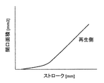
- FIG. 3 is a characteristic diagram showing an opening area characteristic of the regeneration control valve constituting the first embodiment of the hydraulic drive system for the working machine of the present invention.
- the horizontal axis in FIG. 3 indicates the spool stroke of the regeneration control valve 17, and the vertical axis indicates the opening area.
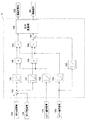
- the operated pilot pressure Pbd is input to the operation portion 5 b of the control valve 5 and the operation portion 16 a of the communication control valve 16.
- the control valve 5 is switched to the position on the left side of the figure, and the bottom pipe line 15 communicates with the tank pipe line 7b, whereby the pressure oil is discharged from the bottom side oil chamber of the boom cylinder 4 to the tank.
- the piston rod performs a reduction operation (boom lowering operation).
- the multiplier 138 inputs the pump reduced flow rate calculated by the function generator 133 and the value calculated by the function generator 134, and outputs the multiplied value as the pump reduced flow rate.
- the function generator 134 outputs a small value from the range of 0 or more and 1 or less, and outputs the pump reduction flow rate calculated by the function generator 133 as a smaller value.
- the function generator 135 calculates a coefficient used in the multiplier in accordance with the lever operation signal 124 of the second operating device 10, and outputs a minimum value 0 when the lever operation signal 124 is 0. The output is increased as 124 increases, and 1 is output as the maximum value.
- the lever operation signal 124 is input to the function generator 139, and the function generator 139 calculates a pump request flow rate corresponding to the lever operation amount and outputs it to the adder 144.
- the calculated pump request flow rate and pump reduction flow rate are input to the adder 144, and the target pump flow rate is calculated by subtracting the pump reduction flow rate, that is, the regeneration flow rate, from the pump request flow rate and output to the output conversion unit 146.
- the regeneration control valve 17 gradually increases the opening area of the regeneration side passage in accordance with the pressure difference between the pressure in the bottom side oil chamber of the boom cylinder 4 and the discharge pressure of the hydraulic pump 1. Switching shock is suppressed, and good operability can be realized.
- the differential pressure, the operation amount of the first operating device 6 and the operation amount of the second operating device 10 are all small, the opening area of the regeneration side passage of the regeneration control valve 17 is set small, and the tank Since the opening area of the side passage is set large, the tank side flow rate increases even if the regeneration flow rate is small. As a result, the piston rod speed of the boom cylinder desired by the operator can be secured.
- the function generator 132 calculates an opening area to be throttled in the tank side passage by the tank side control valve 41 according to the differential pressure signal obtained by the adder 130.
- the opening area characteristic of the tank side control valve 41 shown in FIG. 6 when the spool stroke is minimum, the opening area is maximized, and the opening area decreases by gradually increasing the stroke. It has become.
- the opening area characteristic of the regeneration side control valve 40 is that the opening area is minimized when the spool stroke is minimum, and the opening area is increased by gradually increasing the stroke. It is a characteristic to
- the output conversion unit 146A converts the corrected opening area of the regeneration-side passage into an electromagnetic valve command 222 and outputs it to the electromagnetic proportional valve 22.
- the stroke of the regeneration side control valve 40 is controlled.
- the regeneration side control valve 40 is set to an opening area corresponding to the pressure difference between the pressure in the bottom side oil chamber of the boom cylinder 4 and the discharge pressure of the hydraulic pump 1, and is discharged from the bottom side oil chamber of the boom cylinder 4. Oil is regenerated to the arm cylinder 8.
Abstract
Description
図1において、第1操作装置6の操作レバー6aがブーム下げ方向BDに操作された場合、第1操作装置6のパイロット弁6bから発生した操作パイロット圧Pbdは制御弁5の操作部5bと連通制御弁16の操作部16aに入力される。それにより制御弁5は図示左側の位置に切換られ、ボトム管路15がタンク管路7bと連通することにより、ブームシリンダ4のボトム側油室から圧油がタンクに排出され、ブームシリンダ4のピストンロッドが縮小動作(ブーム下げ動作)を行う。 Next, an outline of the operation when only boom lowering is performed will be described.
In FIG. 1, when the operating
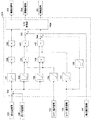
図8は、第2の実施の形態におけるコントローラ27Aの制御ロジックを示すブロック図である。なお、図4と同様の制御要素については説明を割愛する。 Further, the hydraulic drive system of the present embodiment includes a
FIG. 8 is a block diagram showing the control logic of the
Claims (9)
- 油圧ポンプ装置と、前記油圧ポンプ装置から圧油が供給され第1被駆動体を駆動する第1油圧アクチュエータと、前記油圧ポンプ装置から圧油が供給され第2被駆動体を駆動する第2油圧アクチュエータと、前記油圧ポンプ装置から前記第1油圧アクチュエータに供給される圧油の流れを制御する第1流量調整装置と、前記油圧ポンプ装置から前記第2油圧アクチュエータに供給される圧油の流れを制御する第2流量調整装置と、前記第1被駆動体の動作を指令する操作信号を出力し前記第1流量調整装置を切り換える第1操作装置と、前記第2被駆動体の動作を指令する操作信号を出力し前記第2流量調整装置を切り換える第2操作装置とを備え、
前記第1油圧アクチュエータは、前記第1操作装置が前記第1被駆動体の自重落下方向に操作されたときに、前記第1被駆動体の自重落下によりボトム側油室から圧油を排出しロッド側油室から圧油を吸入する油圧シリンダである作業機械の油圧駆動システムにおいて、
前記油圧シリンダのボトム側油室を前記油圧ポンプ装置と前記第2油圧アクチュエータとの間に接続する再生通路と、前記油圧シリンダのボトム側油室から排出される圧油の少なくとも一部を前記再生通路を介して前記油圧ポンプ装置と前記第2油圧アクチュエータの間に供給する再生流量調整装置と、
前記油圧シリンダのボトム側油室の圧力を検出する第1圧力検出器が検出した前記油圧シリンダのボトム側油室の圧力、および前記油圧ポンプ装置と前記第2油圧アクチュエータの間の圧力を検出する第2圧力検出器が検出した前記油圧ポンプ装置と前記第2油圧アクチュエータの間の圧力とを読み込み、差圧を算出する差圧算出部、又は前記油圧シリンダのボトム側油室の圧力と,前記油圧ポンプ装置と前記第2油圧アクチュエータの間の圧力との差圧を検出する差圧検出器と、
前記差圧算出部が算出した差圧、又は前記差圧検出器が検出した差圧の増加に応じて前記再生通路を流れる圧油の流量を徐々に増加させるように前記再生流量調整装置を制御する制御装置を備えた
ことを特徴とする作業機械の油圧駆動システム。 A hydraulic pump device, a first hydraulic actuator supplied with pressure oil from the hydraulic pump device to drive a first driven body, and a second hydraulic pressure supplied with pressure oil from the hydraulic pump device to drive a second driven body. An actuator, a first flow rate adjusting device that controls a flow of pressure oil supplied from the hydraulic pump device to the first hydraulic actuator, and a flow of pressure oil supplied from the hydraulic pump device to the second hydraulic actuator. A second flow control device to be controlled, a first operation device that outputs an operation signal for instructing an operation of the first driven body to switch the first flow adjustment device, and an instruction for the operation of the second driven body. A second operating device that outputs an operation signal and switches the second flow rate adjusting device;
The first hydraulic actuator discharges pressure oil from the bottom side oil chamber when the first operating device is operated in the direction in which the first driven body is dropped by its own weight. In a hydraulic drive system of a work machine that is a hydraulic cylinder that sucks pressure oil from a rod side oil chamber,
A regeneration passage connecting the bottom side oil chamber of the hydraulic cylinder between the hydraulic pump device and the second hydraulic actuator, and at least part of the pressure oil discharged from the bottom side oil chamber of the hydraulic cylinder is regenerated. A regenerative flow rate adjusting device for supplying between the hydraulic pump device and the second hydraulic actuator via a passage;
The pressure of the bottom side oil chamber of the hydraulic cylinder detected by the first pressure detector that detects the pressure of the bottom side oil chamber of the hydraulic cylinder and the pressure between the hydraulic pump device and the second hydraulic actuator are detected. The pressure between the hydraulic pump device and the second hydraulic actuator detected by the second pressure detector is read to calculate a differential pressure, or the pressure in the bottom oil chamber of the hydraulic cylinder, A differential pressure detector for detecting a differential pressure between a hydraulic pump device and a pressure between the second hydraulic actuator;
The regeneration flow rate adjusting device is controlled so as to gradually increase the flow rate of the pressure oil flowing through the regeneration passage according to an increase in the differential pressure calculated by the differential pressure calculation unit or the differential pressure detected by the differential pressure detector. A hydraulic drive system for a work machine, characterized in that a control device is provided. - 請求項1に記載の作業機械の油圧駆動システムにおいて、
前記油圧ポンプ装置は少なくとも1つの可変容量型の油圧ポンプを含み、
前記可変容量型の油圧ポンプは、吐出流量を調整可能とする吐出流量調整装置を備え、
前記制御装置は前記差圧算出部が算出した差圧、又は前記差圧検出器が検出した差圧に応じて、前記油圧ポンプ装置の吐出流量を制御するために、前記吐出流量調整装置を制御する
ことを特徴とする作業機械の油圧駆動システム。 The hydraulic drive system for a work machine according to claim 1,
The hydraulic pump device includes at least one variable displacement hydraulic pump;
The variable displacement hydraulic pump includes a discharge flow rate adjustment device that enables adjustment of the discharge flow rate,
The control device controls the discharge flow rate adjusting device to control the discharge flow rate of the hydraulic pump device according to the differential pressure calculated by the differential pressure calculation unit or the differential pressure detected by the differential pressure detector. A hydraulic drive system for a work machine. - 請求項1に記載の作業機械の油圧駆動システムにおいて、
前記油圧シリンダのボトム側油室から排出される圧油の少なくとも一部をタンクに排出する排出流量調整装置をさらに備え、
前記制御装置は前記差圧算出部が算出した差圧、又は前記差圧検出器が検出した差圧に応じて、前記タンクに排出する圧油の排出流量を制御するために、前記排出流量調整装置を制御する
ことを特徴とする作業機械の油圧駆動システム。 The hydraulic drive system for a work machine according to claim 1,
A discharge flow rate adjusting device for discharging at least part of the pressure oil discharged from the bottom side oil chamber of the hydraulic cylinder to the tank;
The control device adjusts the discharge flow rate in order to control the discharge flow rate of the pressure oil discharged to the tank according to the differential pressure calculated by the differential pressure calculation unit or the differential pressure detected by the differential pressure detector. A hydraulic drive system for a work machine characterized by controlling the device. - 請求項2に記載の作業機械の油圧駆動システムにおいて、
前記油圧シリンダのボトム側油室から排出される圧油の少なくとも一部をタンクに排出する排出流量調整装置をさらに備え、
前記制御装置は前記差圧算出部が算出した差圧、又は前記差圧検出器が検出した差圧に応じて、前記タンクに排出する圧油の排出流量を制御するために、前記排出流量調整装置を制御する
ことを特徴とする作業機械の油圧駆動システム。 The hydraulic drive system for a work machine according to claim 2,
A discharge flow rate adjusting device for discharging at least part of the pressure oil discharged from the bottom side oil chamber of the hydraulic cylinder to the tank;
The control device adjusts the discharge flow rate in order to control the discharge flow rate of the pressure oil discharged to the tank according to the differential pressure calculated by the differential pressure calculation unit or the differential pressure detected by the differential pressure detector. A hydraulic drive system for a work machine characterized by controlling the device. - 請求項4に記載の作業機械の油圧駆動システムにおいて、
前記第1操作装置の操作量を検出する第1操作量検出器と、前記第2操作装置の操作量を検出する第2操作量検出器とをさらに備え、
前記制御装置は、前記第1操作量検出器が検出した前記第1操作装置の操作量と前記第2操作量検出器が検出した前記第2操作装置の操作量とを読み込み、前記第1操作装置、または前記第2操作装置の少なくとも一方の操作量に応じて、前記再生流量調整装置、前記排出流量調整装置、または前記吐出流量調整装置の少なくともいずれか一つを制御する
ことを特徴とする作業機械の油圧駆動システム。 The hydraulic drive system for a work machine according to claim 4,
A first operation amount detector that detects an operation amount of the first operation device; and a second operation amount detector that detects an operation amount of the second operation device;
The control device reads the operation amount of the first operation device detected by the first operation amount detector and the operation amount of the second operation device detected by the second operation amount detector, and performs the first operation. The at least one of the regeneration flow rate adjusting device, the discharge flow rate adjusting device, and the discharge flow rate adjusting device is controlled in accordance with an operation amount of at least one of the device and the second operating device. Hydraulic drive system for work machines. - 請求項5に記載の作業機械の油圧駆動システムにおいて、
前記制御装置は、前記第1操作装置、または前記第2操作装置の少なくとも一方の操作量が一定量のときは、前記差圧算出部が算出した差圧、又は前記差圧検出器が検出した差圧の増加に応じて前記再生通路を流れる圧油の流量を増加させるように前記再生流量調整装置を制御する
ことを特徴とする作業機械の油圧駆動システム。 The hydraulic drive system for a work machine according to claim 5,
When the operation amount of at least one of the first operation device or the second operation device is a constant amount, the control device detects the differential pressure calculated by the differential pressure calculation unit or the differential pressure detector. A hydraulic drive system for a work machine, wherein the regeneration flow rate adjusting device is controlled so as to increase a flow rate of pressure oil flowing through the regeneration passage according to an increase in differential pressure. - 請求項5に記載の作業機械の油圧駆動システムにおいて、
前記制御装置は、前記差圧算出部が算出した差圧、又は前記差圧検出器が検出した差圧が一定量のときは、前記第1操作装置の操作量の増加または前記第2操作装置の操作量の増加に応じて、前記再生通路を流れる圧油の流量を増加させるように前記再生流量調整装置を制御する
ことを特徴とする作業機械の油圧駆動システム。 The hydraulic drive system for a work machine according to claim 5,
When the differential pressure calculated by the differential pressure calculation unit or the differential pressure detected by the differential pressure detector is a constant amount, the control device increases the operation amount of the first operation device or the second operation device. A hydraulic drive system for a working machine, wherein the regeneration flow rate adjusting device is controlled to increase the flow rate of the pressure oil flowing through the regeneration passage according to an increase in the operation amount. - 請求項4に記載の作業機械の油圧駆動システムにおいて、
前記再生流量調整装置と前記排出流量調整装置は、再生側絞りと排出側絞りを有する1つの再生制御弁である
ことを特徴とする作業機械の油圧駆動システム。 The hydraulic drive system for a work machine according to claim 4,
The hydraulic drive system for a work machine, wherein the regeneration flow rate adjusting device and the discharge flow rate adjusting device are one regeneration control valve having a regeneration side throttle and a discharge side throttle. - 請求項4に記載の作業機械の油圧駆動システムにおいて、
前記再生流量調整装置は再生流量を調整する再生弁であり、前記排出流量調整装置は排出流量を調整する排出弁である
ことを特徴とする作業機械の油圧駆動システム。 The hydraulic drive system for a work machine according to claim 4,
The hydraulic drive system for a work machine, wherein the regeneration flow rate adjusting device is a regeneration valve that adjusts the regeneration flow rate, and the exhaust flow rate adjusting device is a discharge valve that adjusts the discharge flow rate.
Priority Applications (4)
| Application Number | Priority Date | Filing Date | Title |
|---|---|---|---|
| US15/501,927 US10227997B2 (en) | 2014-10-02 | 2015-09-16 | Hydraulic drive system for work machine |
| CN201580043504.4A CN106662131B (en) | 2014-10-02 | 2015-09-16 | The fluid power system of Work machine |
| KR1020177003467A KR101973872B1 (en) | 2014-10-02 | 2015-09-16 | Hydraulic drive system for work machine |
| EP15847051.8A EP3203089B1 (en) | 2014-10-02 | 2015-09-16 | Workmachine comprising a hydraulic drive system |
Applications Claiming Priority (2)
| Application Number | Priority Date | Filing Date | Title |
|---|---|---|---|
| JP2014-204348 | 2014-10-02 | ||
| JP2014204348A JP6317656B2 (en) | 2014-10-02 | 2014-10-02 | Hydraulic drive system for work machines |
Publications (1)
| Publication Number | Publication Date |
|---|---|
| WO2016052209A1 true WO2016052209A1 (en) | 2016-04-07 |
Family
ID=55630251
Family Applications (1)
| Application Number | Title | Priority Date | Filing Date |
|---|---|---|---|
| PCT/JP2015/076349 WO2016052209A1 (en) | 2014-10-02 | 2015-09-16 | Work vehicle hydraulic drive system |
Country Status (6)
| Country | Link |
|---|---|
| US (1) | US10227997B2 (en) |
| EP (1) | EP3203089B1 (en) |
| JP (1) | JP6317656B2 (en) |
| KR (1) | KR101973872B1 (en) |
| CN (1) | CN106662131B (en) |
| WO (1) | WO2016052209A1 (en) |
Families Citing this family (14)
| Publication number | Priority date | Publication date | Assignee | Title |
|---|---|---|---|---|
| JP6316776B2 (en) * | 2015-06-09 | 2018-04-25 | 日立建機株式会社 | Hydraulic drive system for work machines |
| EP3517789B1 (en) * | 2016-09-23 | 2023-09-13 | Hitachi Construction Machinery Co., Ltd. | Hydraulic energy recovery device for work machine |
| JP6879632B2 (en) * | 2017-07-18 | 2021-06-02 | キャタピラー エス エー アール エル | Work machine control device |
| CN107724455B (en) * | 2017-11-22 | 2023-07-07 | 江苏恒立液压科技有限公司 | Hydraulic circuit of engineering machine, engineering machine with hydraulic circuit and control method |
| US11346081B2 (en) * | 2018-03-15 | 2022-05-31 | Hitachi Construction Machinery Co., Ltd. | Construction machine |
| CN110486341B (en) * | 2018-05-14 | 2023-03-21 | 博世力士乐(北京)液压有限公司 | Hydraulic control system and mobile working equipment |
| JP7065736B2 (en) * | 2018-09-11 | 2022-05-12 | 日立建機株式会社 | Construction machinery and control systems for construction machinery |
| US11655130B2 (en) | 2019-05-22 | 2023-05-23 | Cascade Corporation | Synchronized hybrid clamp force controller for lift truck attachment |
| US11220417B2 (en) | 2019-05-22 | 2022-01-11 | Cascade Corporation | Hybrid clamp force control for lift truck attachment |
| CN114207296A (en) * | 2019-07-08 | 2022-03-18 | 丹佛斯动力系统Ii技术有限公司 | Hydraulic system architecture and two-way proportional valve usable in the system architecture |
| JP7338292B2 (en) * | 2019-07-19 | 2023-09-05 | コベルコ建機株式会社 | Hydraulic controller for construction machinery |
| US11447930B2 (en) | 2019-09-24 | 2022-09-20 | Clark Equipment Company | System and methods for cycle time management |
| CN112555207A (en) * | 2020-12-01 | 2021-03-26 | 上海华兴数字科技有限公司 | Hydraulic control system and mechanical equipment |
| CN115234543A (en) * | 2022-07-15 | 2022-10-25 | 烟台杰瑞石油装备技术有限公司 | Hydraulic monitoring system |
Citations (3)
| Publication number | Priority date | Publication date | Assignee | Title |
|---|---|---|---|---|
| JPS60179504A (en) * | 1984-02-28 | 1985-09-13 | Mitsubishi Heavy Ind Ltd | Energy recycle circuit |
| JP2013053498A (en) * | 2011-09-06 | 2013-03-21 | Sumitomo (Shi) Construction Machinery Co Ltd | Construction machine |
| JP2013204223A (en) * | 2012-03-27 | 2013-10-07 | Kobelco Contstruction Machinery Ltd | Control device and construction machine with the same |
Family Cites Families (6)
| Publication number | Priority date | Publication date | Assignee | Title |
|---|---|---|---|---|
| CN1753831A (en) | 2003-02-27 | 2006-03-29 | 日立建机株式会社 | Hydraulic control device of hydraulic working machine |
| JP5354650B2 (en) | 2008-10-22 | 2013-11-27 | キャタピラー エス エー アール エル | Hydraulic control system for work machines |
| JP5461234B2 (en) | 2010-02-26 | 2014-04-02 | カヤバ工業株式会社 | Construction machine control equipment |
| US9284718B2 (en) | 2011-06-15 | 2016-03-15 | Hitachi Construction Machinery Co., Ltd. | Power regeneration device for operating machine |
| EP2730704B1 (en) * | 2011-07-06 | 2017-08-30 | Sumitomo Heavy Industries, Ltd. | Regenerative hydraulic circuit for a shovel and method for controlling a shovel |
| JP5938356B2 (en) * | 2013-02-22 | 2016-06-22 | 日立建機株式会社 | Hydraulic drive device for hydraulic excavator |
-
2014
- 2014-10-02 JP JP2014204348A patent/JP6317656B2/en active Active
-
2015
- 2015-09-16 KR KR1020177003467A patent/KR101973872B1/en active IP Right Grant
- 2015-09-16 EP EP15847051.8A patent/EP3203089B1/en active Active
- 2015-09-16 US US15/501,927 patent/US10227997B2/en active Active
- 2015-09-16 WO PCT/JP2015/076349 patent/WO2016052209A1/en active Application Filing
- 2015-09-16 CN CN201580043504.4A patent/CN106662131B/en active Active
Patent Citations (3)
| Publication number | Priority date | Publication date | Assignee | Title |
|---|---|---|---|---|
| JPS60179504A (en) * | 1984-02-28 | 1985-09-13 | Mitsubishi Heavy Ind Ltd | Energy recycle circuit |
| JP2013053498A (en) * | 2011-09-06 | 2013-03-21 | Sumitomo (Shi) Construction Machinery Co Ltd | Construction machine |
| JP2013204223A (en) * | 2012-03-27 | 2013-10-07 | Kobelco Contstruction Machinery Ltd | Control device and construction machine with the same |
Non-Patent Citations (1)
| Title |
|---|
| See also references of EP3203089A4 * |
Also Published As
| Publication number | Publication date |
|---|---|
| JP6317656B2 (en) | 2018-04-25 |
| EP3203089B1 (en) | 2022-04-13 |
| JP2016075301A (en) | 2016-05-12 |
| US20170234334A1 (en) | 2017-08-17 |
| US10227997B2 (en) | 2019-03-12 |
| EP3203089A1 (en) | 2017-08-09 |
| CN106662131A (en) | 2017-05-10 |
| KR101973872B1 (en) | 2019-04-29 |
| KR20170026627A (en) | 2017-03-08 |
| EP3203089A4 (en) | 2018-06-27 |
| CN106662131B (en) | 2018-07-03 |
Similar Documents
| Publication | Publication Date | Title |
|---|---|---|
| JP6317656B2 (en) | Hydraulic drive system for work machines | |
| JP6291394B2 (en) | Hydraulic drive system for work machines | |
| JP6453898B2 (en) | Hydraulic drive system for work machines | |
| KR102062193B1 (en) | Hydraulic oil regenerative device of working machine | |
| JP6360824B2 (en) | Work machine | |
| WO2017056199A1 (en) | Construction machine | |
| JP2010078035A (en) | Hydraulic cylinder control circuit of utility machine | |
| WO2019049435A1 (en) | Construction machine | |
| KR102460499B1 (en) | shovel | |
| KR101747519B1 (en) | Hybrid construction machine | |
| JP6891079B2 (en) | Hydraulic drive system for construction machinery | |
| JP2015172400A (en) | Shovel | |
| JP6591370B2 (en) | Hydraulic control equipment for construction machinery | |
| JP6580301B2 (en) | Excavator | |
| JP6989548B2 (en) | Construction machinery | |
| JP2015172398A (en) | Shovel | |
| JP2015172397A (en) | Shovel | |
| JP2014105541A (en) | Work machine | |
| JP2015172394A (en) | Shovel | |
| JP2015172399A (en) | Shovel |
Legal Events
| Date | Code | Title | Description |
|---|---|---|---|
| 121 | Ep: the epo has been informed by wipo that ep was designated in this application |
Ref document number: 15847051 Country of ref document: EP Kind code of ref document: A1 |
|
| REEP | Request for entry into the european phase |
Ref document number: 2015847051 Country of ref document: EP |
|
| WWE | Wipo information: entry into national phase |
Ref document number: 2015847051 Country of ref document: EP |
|
| ENP | Entry into the national phase |
Ref document number: 20177003467 Country of ref document: KR Kind code of ref document: A |
|
| NENP | Non-entry into the national phase |
Ref country code: DE |