WO2016047728A1 - User terminal, wireless communication system, and wireless communication method - Google Patents
User terminal, wireless communication system, and wireless communication method Download PDFInfo
- Publication number
- WO2016047728A1 WO2016047728A1 PCT/JP2015/077044 JP2015077044W WO2016047728A1 WO 2016047728 A1 WO2016047728 A1 WO 2016047728A1 JP 2015077044 W JP2015077044 W JP 2015077044W WO 2016047728 A1 WO2016047728 A1 WO 2016047728A1
- Authority
- WO
- WIPO (PCT)
- Prior art keywords
- control
- dual connectivity
- user terminal
- base station
- synchronous
- Prior art date
Links
Images


Classifications
-
- H—ELECTRICITY
- H04—ELECTRIC COMMUNICATION TECHNIQUE
- H04W—WIRELESS COMMUNICATION NETWORKS
- H04W72/00—Local resource management
- H04W72/20—Control channels or signalling for resource management
-
- H—ELECTRICITY
- H04—ELECTRIC COMMUNICATION TECHNIQUE
- H04W—WIRELESS COMMUNICATION NETWORKS
- H04W16/00—Network planning, e.g. coverage or traffic planning tools; Network deployment, e.g. resource partitioning or cells structures
- H04W16/24—Cell structures
- H04W16/32—Hierarchical cell structures
-
- H—ELECTRICITY
- H04—ELECTRIC COMMUNICATION TECHNIQUE
- H04W—WIRELESS COMMUNICATION NETWORKS
- H04W52/00—Power management, e.g. TPC [Transmission Power Control], power saving or power classes
- H04W52/04—TPC
- H04W52/06—TPC algorithms
- H04W52/14—Separate analysis of uplink or downlink
- H04W52/146—Uplink power control
-
- H—ELECTRICITY
- H04—ELECTRIC COMMUNICATION TECHNIQUE
- H04W—WIRELESS COMMUNICATION NETWORKS
- H04W52/00—Power management, e.g. TPC [Transmission Power Control], power saving or power classes
- H04W52/04—TPC
- H04W52/30—TPC using constraints in the total amount of available transmission power
-
- H—ELECTRICITY
- H04—ELECTRIC COMMUNICATION TECHNIQUE
- H04W—WIRELESS COMMUNICATION NETWORKS
- H04W52/00—Power management, e.g. TPC [Transmission Power Control], power saving or power classes
- H04W52/04—TPC
- H04W52/30—TPC using constraints in the total amount of available transmission power
- H04W52/34—TPC management, i.e. sharing limited amount of power among users or channels or data types, e.g. cell loading
-
- H—ELECTRICITY
- H04—ELECTRIC COMMUNICATION TECHNIQUE
- H04W—WIRELESS COMMUNICATION NETWORKS
- H04W56/00—Synchronisation arrangements
- H04W56/001—Synchronization between nodes
-
- H—ELECTRICITY
- H04—ELECTRIC COMMUNICATION TECHNIQUE
- H04W—WIRELESS COMMUNICATION NETWORKS
- H04W72/00—Local resource management
- H04W72/04—Wireless resource allocation
-
- H—ELECTRICITY
- H04—ELECTRIC COMMUNICATION TECHNIQUE
- H04W—WIRELESS COMMUNICATION NETWORKS
- H04W72/00—Local resource management
- H04W72/04—Wireless resource allocation
- H04W72/044—Wireless resource allocation based on the type of the allocated resource
- H04W72/0453—Resources in frequency domain, e.g. a carrier in FDMA
-
- H—ELECTRICITY
- H04—ELECTRIC COMMUNICATION TECHNIQUE
- H04W—WIRELESS COMMUNICATION NETWORKS
- H04W52/00—Power management, e.g. TPC [Transmission Power Control], power saving or power classes
- H04W52/04—TPC
- H04W52/30—TPC using constraints in the total amount of available transmission power
- H04W52/36—TPC using constraints in the total amount of available transmission power with a discrete range or set of values, e.g. step size, ramping or offsets
- H04W52/367—Power values between minimum and maximum limits, e.g. dynamic range
-
- H—ELECTRICITY
- H04—ELECTRIC COMMUNICATION TECHNIQUE
- H04W—WIRELESS COMMUNICATION NETWORKS
- H04W88/00—Devices specially adapted for wireless communication networks, e.g. terminals, base stations or access point devices
- H04W88/02—Terminal devices
- H04W88/06—Terminal devices adapted for operation in multiple networks or having at least two operational modes, e.g. multi-mode terminals
Definitions
- the present invention relates to a user terminal, a radio communication system, and a radio communication method in a next generation mobile communication system.
- Non-patent Document 1 In the UMTS (universal mobile telecommunications system) network, long term evolution (LTE) has been specified for the purpose of higher data rates, lower delay, etc. (Non-patent Document 1).
- LTE uses multiple access schemes based on OFDMA (orthogonal frequency division multiple access) for the downlink (downlink) and SC-FDMA (single carrier frequency division multiple access) for the uplink (uplink). Is used.
- OFDMA orthogonal frequency division multiple access
- SC-FDMA single carrier frequency division multiple access
- LTE Advanced or LTE enhancement has been studied, and LTE Rel. It is specified as 10/11.
- the 10/11 system band includes at least one component carrier (CC) having the system band of the LTE system as one unit.
- CC component carrier
- CA carrier aggregation
- LTE Rel. Is a further successor system of LTE. 12, various scenarios in which a plurality of cells are used in different frequency bands (carriers) are being studied.
- carriers frequency bands
- the radio base stations forming a plurality of cells are substantially the same, the above-described carrier aggregation can be applied.
- dual connectivity DC
- E-UTRA Evolved Universal Terrestrial Radio Access
- E-UTRAN Evolved Universal Terrestrial Radio Access Network
- the present invention has been made in view of the above points, and provides a user terminal, a wireless communication system, and a wireless communication method capable of appropriately applying control for synchronous dual connectivity and control for asynchronous dual connectivity in dual connectivity. For the purpose.
- the user terminal of the present invention is a user terminal that communicates with a plurality of cell groups each composed of one or more cells using different frequencies, and is synchronized based on an index at the time when an event in an upper layer occurs
- the control is not switched to the other dual connectivity control, and the other dual connectivity control is limited to the specified number of times. It has the control part which performs either of the control to switch.
- control for synchronous dual connectivity and control for asynchronous dual connectivity can be appropriately applied.
- HetNet heterogeneous network
- Carrier aggregation and dual connectivity can be applied to HetNet configurations.
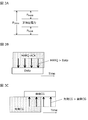
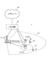
- FIG. 1A shows communication between a radio base station and a user terminal related to carrier aggregation.
- the radio base station eNB1 is a radio base station forming a macro cell (hereinafter referred to as a macro base station), and the radio base station eNB2 is a radio base station forming a small cell (hereinafter referred to as a small base station).
- the small base station may be configured as an RRH (remote radio head) connected to the macro base station.
- RRH remote radio head
- one scheduler controls scheduling of a plurality of cells.
- the scheduler of the macro base station eNB1 controls the scheduling of a plurality of cells.
- the radio base stations are connected by an ideal backhaul such as a high-speed line such as an optical fiber.
- FIG. 1B shows communication between a radio base station and a user terminal related to dual connectivity.
- a plurality of schedulers are provided independently, and each of the plurality of schedulers controls the scheduling of one or more cells under its jurisdiction.
- the scheduler of the master base station (MeNB: master eNB) schedules component carriers belonging to the master cell group (MCG: master cell group).
- the secondary base station (scheduler of the SeNB: secondary eNB) performs scheduling of component carriers belonging to the secondary cell group (SCG).
- SCG secondary cell group
- LTE Rel. 10/11 Carrier aggregation is applicable.
- the total number of cells constituting the master cell group and the secondary cell group is set to be a predetermined value (for example, 5 cells) or less.
- a non-ideal backhaul with non-negligible delay such as an X2 interface
- X2 interface non-ideal backhaul with non-negligible delay
- each radio base station is connected by ideal backhaul. Therefore, it is assumed that dynamic cooperative control corresponding to the subframe length is impossible between the scheduling of the master cell group and the secondary cell group.
- two operations are possible: a case where the master base station MeNB and the secondary base station SeNB are synchronized with a certain accuracy and a case where no synchronization is assumed.
- the user terminal In dual connectivity, wireless base stations do not assume tight cooperation equivalent to carrier aggregation. Therefore, the user terminal independently performs downlink L1 / L2 control (PDCCH / EPDCCH) and uplink L1 / L2 control (UCI (uplink control information) feedback by PUCCH / PUSCH) for each cell group.
- PUCCH / EPDCCH downlink L1 / L2 control
- UCI uplink L1 / L2 control information
- a common search space, PUCCH, and PSCell having the same functions as the primary cell (PCell: primary cell) such as always activated are set. Yes.
- the master base station MeNB and the secondary base station SeNB schedule each independently. Therefore, it is difficult to perform transmission power control that dynamically adjusts transmission power in a range in which the total transmission power of the user terminal for the master base station MeNB and the secondary base station SeNB does not exceed the allowable maximum transmission power P CMAX. .
- the user terminal scales down the power until it becomes a value not exceeding the allowable maximum transmission power P CMAX (power scaling), or A process of dropping (dropping) some or all channels or signals is performed.
- the master base station MeNB and the secondary base station SeNB each control what kind of power control the paired radio base stations (secondary base station SeNB for the master base station MeNB and master base station MeNB for the secondary base station SeNB) have. I can't figure out what is going on. Therefore, there is a possibility that the timing and frequency at which power scaling and dropping by the user terminal occur cannot be assumed. For the master base station MeNB and the secondary base station SeNB, when unexpected power scaling or dropping is performed, uplink communication cannot be performed correctly, and communication quality and throughput may be significantly degraded.
- the concept of “minimum guaranteed power” for each cell group is introduced at least for PUCCH / PUSCH transmission.
- the guaranteed transmission power of the master cell group (MCG) is P MeNB
- the guaranteed transmission power of the secondary cell group (SCG) is P SeNB .
- the master base station MeNB or the secondary base station SeNB notifies the user terminal of both or one of the guaranteed transmission powers P MeNB and P SeNB by higher layer signaling such as RRC.
- the user terminal may recognize that the guaranteed transmission powers P MeNB and P SeNB or one of the values is 0.
- the user terminal When there is a transmission request from the master base station MeNB, that is, when the transmission of PUCCH / PUSCH is triggered by the uplink grant or RRC (radio resource control), the user terminal transmits power to the master cell group (MCG). If the required transmission power (required power) is equal to or lower than the guaranteed transmission power P MeNB , the required power is determined as the transmission power of the master cell group (MCG).
- the user terminal When there is a transmission request from the secondary base station SeNB, that is, when the transmission of the PUCCH / PUSCH is triggered by the uplink grant or RRC, the user terminal calculates the transmission power to the secondary group (SCG), and If the transmission power (required power) to be performed is equal to or lower than the guaranteed transmission power P SeNB , the required power is determined as the transmission power of the secondary cell group (SCG).
- the user terminal can perform power scaling and dropping. Do not do.
- the user terminal may control the transmission power to be equal to or less than the guaranteed transmission power PxeNB depending on conditions. Specifically, when the total required power of the master cell group and the secondary cell group may exceed the allowable maximum transmission power P CMAX of the user terminal, the user terminal is required to have a power exceeding the guaranteed transmission power PxeNB. Perform power scaling and channel or signal dropping for the selected cell group. As a result, when the transmission power becomes equal to or less than the guaranteed transmission power PxeNB , the user terminal does not perform further power scaling or channel or signal dropping.
- the user terminal In the case of synchronous dual connectivity (see FIG. 2A), if the sum of the required power requested from the master base station and the secondary base station at the same timing exceeds the maximum allowable transmission power P CMAX of the user terminal, the user terminal This is the condition for dropping. In this case, the user terminal performs power scaling or dropping on the cell group in which the transmission power per cell group exceeds the guaranteed transmission power PxeNB, and the total transmission power per user terminal is the allowable maximum transmission power P of the user terminal. Control is performed so as not to exceed CMAX (condition 1).
- the guaranteed transmission power PxeNB may be set so that the total of all the set guaranteed transmission powers PxeNB does not become 100%.
- the guaranteed transmission power P MeNB of the master cell group can be set to 30%
- the guaranteed transmission power P SeNB of the secondary cell group can be set to 30%.
- non-guaranteed power at which power allocation is not guaranteed for any radio base station xeNB is 40% (see FIG. 3A).
- non-guaranteed power is preferentially allocated to channels or control information with higher priority according to the priority defined for each channel or control information to be transmitted.
- power is insufficient, power is not allocated to low priority channels or control information.
- the HARQ-ACK hybrid automatic repeat request-acknowledge
- the HARQ-ACK has a higher priority than the data, so power is preferentially allocated to the HARQ-ACK.
- non-guaranteed power is allocated with priority given to cell groups that have already been transmitted (starting cell groups).
- starting cell groups When power is insufficient in the subsequent cell group, power is distributed in the cell group according to the priority of the channel or control information in the cell group.
- the subsequent cell group since the preceding cell group to which power allocation has already been performed is prioritized, the subsequent cell group cannot take the power allocated to the preceding cell group.
- suitable transmission power control differs between synchronous dual connectivity and asynchronous dual connectivity.
- a transmission timing difference between cell groups is a predetermined value (for example, 33 + ⁇ [ ⁇ s], where 33 [ ⁇ s] is a reception timing difference between cell groups, and ⁇ is a reception timing difference. This is applied when it is within (additional timing difference added by processing inside the terminal).
- Asynchronous dual connectivity transmission power control is applied when a transmission timing difference between cell groups exceeds a predetermined value (for example, 33 + ⁇ [ ⁇ s]).
- Synchronous dual connectivity and asynchronous dual connectivity may be referred to as DC mode 1 and DC mode 2, respectively.
- transmission power control suitable for synchronous dual connectivity transmission power control for synchronous dual connectivity or DC power-control (PC) mode 1 transmission power control suitable for asynchronous dual connectivity or transmission power control for asynchronous dual connectivity or DC power -It may be called control (PC) mode 2.
- the guaranteed transmission power P xeNB is interpreted as power preferentially allocated to the cell group (xCG).
- the guaranteed transmission power P xeNB is interpreted as the power allocated exclusively to the cell group (xCG).
- the guaranteed transmission power P MeNB is power that is not allocated to the secondary cell group (SCG).
- non-guaranteed power is allocated according to the priority order of channels and control information.
- the priority order of channels and control information is defined as, for example, HARQ-ACK or scheduling request signal (SR: scheduling request signal)> channel state information (CSI: channel state information)> data> sounding reference signal (SRS) Is done.
- SR scheduling request signal
- CSI channel state information
- SRS sounding reference signal
- transmission power control for synchronous dual connectivity and transmission power control for asynchronous dual connectivity are defined. However, there is a case where no conclusion has been made as to which transmission power control should be performed.
- the master base station MeNB and the secondary base station SeNB are synchronized, the case where the transmission timing difference between the cell groups in a user terminal exceeds a predetermined value (for example, 33 + ⁇ [ ⁇ s]) can be considered.
- a predetermined value for example, 33 + ⁇ [ ⁇ s]
- the propagation path difference from the radio base station xeNB to the user terminal is greater than or equal to the assumption of the master base station MeNB and the secondary base station SeNB.
- this case cannot occur if the station is correctly placed.
- the master base station MeNB and the secondary base station SeNB are asynchronous, there may be a case where the transmission timing difference between the cell groups in the user terminal is within a predetermined value (for example, 33 + ⁇ [ ⁇ s]). This is a case where the user terminal happens to communicate at a place where the reception timing difference becomes very small. This case can occur with a certain probability in asynchronous dual connectivity, and cannot be solved by a station or the like as long as the master base station MeNB and the secondary base station SeNB are asynchronous.
- a predetermined value for example, 33 + ⁇ [ ⁇ s]
- the user terminal autonomously switches between transmission power control for synchronous dual connectivity and transmission power control for asynchronous dual connectivity depending on whether or not the transmission timing difference is within a predetermined value (for example, 33 + ⁇ [ ⁇ s]). Yes.
- the radio base station xeNB cannot recognize which transmission power control is applied to the user terminal. Accordingly, there is a possibility that the assumed transmission power control does not match between the radio base station x eNB side and the user terminal side.
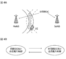
- FIG. 4A A user terminal in an area where the transmission or reception timing difference happens to be very small (area hatched in FIG. 4A) may change the propagation path or the distance to the radio base station xeNB due to its movement or surrounding environment change. May change.
- the user terminal applies the timing advance control of the radio base station xeNB or the timing adjustment control of the terminal itself, and the transmission timing difference exceeds a predetermined value (for example, 33 + ⁇ [ ⁇ s]) within a short time, (For example, 33 + ⁇ [ ⁇ s]) (see FIG. 4A).
- a predetermined value for example, 33 + ⁇ [ ⁇ s]
- the user terminal switches between two transmission power controls (ping-pong problem), and there is a possibility that the battery of the user terminal is consumed unnecessarily (see FIG. 4B).
- the radio base station xeNB adopts a method for instructing transmission power control to be applied to the user terminal, the recognition mismatch and the ping-pong problem do not occur.
- the master base station MeNB and the secondary base station SeNB are predetermined for the user terminal by RRC signaling, MAC signaling, or the like at the same time or after the dual connectivity setting for the user terminal for which the master base station MeNB sets dual connectivity. It is notified whether it is synchronized so that it may fall within the timing or which transmission power control should be used to the user terminal. When the user terminal detects the signaling, the user terminal switches to the notified transmission power within a predetermined time.
- this method has a problem that signaling overhead increases.
- the transmission power control for synchronous dual connectivity is more efficient than the transmission power control for asynchronous dual connectivity. Therefore, when the user terminal applies the transmission power control for asynchronous dual connectivity, the recognition mismatch that the radio base station x eNB recognizes that the transmission power control for synchronous dual connectivity is applied at the user terminal becomes a problem. According to such recognition mismatch, based on the case where the user terminal cannot allocate the required power for the power allocation of the radio base station xeNB, or based on uplink control information (UCI) from the radio base station xeNB This is because there is a case where power is not allocated with priority.
- UCI uplink control information
- the recognition mismatch that the radio base station x eNB recognizes that the transmission power control for asynchronous dual connectivity is applied in the user terminal is not a problem. This is because the user terminal has the ability to allocate more power to the power allocation of the radio base station xeNB. Moreover, since the radio base station x eNB assumes transmission power control for asynchronous dual connectivity, it does not expect efficient power control for the user terminal.
- the radio base station x eNB When the radio base station x eNB recognizes that the transmission power control for asynchronous dual connectivity is applied, the radio base station x eNB performs power allocation on the assumption that the transmission power control for asynchronous dual connectivity is applied. At this time, even if the user terminal applies transmission power control for synchronous dual connectivity, no particular problem occurs.
- the radio base station x eNB recognizes that transmission power control for synchronous dual connectivity is applied, a transmission timing difference exceeding a predetermined value (for example, 33 + ⁇ [ ⁇ s]) is observed at the user terminal, and thus the asynchronous dual station
- a transmission timing difference exceeding a predetermined value for example, 33 + ⁇ [ ⁇ s]
- the case where the transmission power control for connectivity is applied is a case where the propagation path difference is very large, and the quality degradation is large not only from the uplink power control but also from the viewpoint of downlink communication quality.
- the present inventors have found a configuration that solves the problem due to the recognition mismatch and the ping-pong problem while avoiding an increase in signaling overhead.
- the user terminal controls transmission power for synchronous dual connectivity or transmission power for asynchronous dual connectivity based on the transmission timing difference observed by the user terminal until the next event occurs. Apply control.
- the specific event in the upper layer corresponds to, for example, dual connectivity configuration (configure).
- the next event corresponds to, for example, dual connectivity reconfiguration.
- the user terminal decides whether to apply transmission power control for synchronous dual connectivity or transmission power control for asynchronous dual connectivity based on observation results at a specific event, and does not switch to another transmission power control. .
- the user terminal determines whether to apply the transmission power control for synchronous dual connectivity or the transmission power control for asynchronous dual connectivity based on the observation result at a specific event time, and then determines a predetermined number of times (for example, once) ) Can only be switched to another transmission power control.
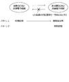
- the transmission power control of the user terminal can be switched only in one direction (see FIG. 5). That is, the transition occurs only once at the maximum, and it is possible to prevent the user terminal existing at the boundary of whether or not to apply the predetermined condition from causing the ping-pong problem.
- the user terminal when the transmission power difference for synchronous dual connectivity is applied and the observed transmission timing difference exceeds a predetermined value (for example, 33 + ⁇ [ ⁇ s]), the user terminal performs asynchronous dual connectivity. Is switched to direct transmission power control (pattern 1).
- a predetermined value for example, 33 + ⁇ [ ⁇ s]
- the user terminal is in a state where transmission power control for asynchronous dual connectivity is applied, and the transmission timing difference to be observed is a predetermined value (for example, 33 + ⁇ [ ⁇ s]) or less.
- the transmission power control for synchronous dual connectivity is not switched (pattern 2).
- a user terminal to which transmission power control for asynchronous dual connectivity is applied does not need to determine whether or not transmission power control for synchronous dual connectivity is applied, so that battery consumption can be suppressed.
- the user terminal may be configured not to switch to transmission power control for synchronous dual connectivity unless there is a change instruction from an upper layer.
- the user terminal transitions from the transmission power control for synchronous dual connectivity to the transmission power control for asynchronous dual connectivity because the transmission timing difference is a predetermined value (for example, 33 + ⁇ [ ⁇ s]). Since this represents a state in which the timing difference is not assumed on the network side, the communication quality cannot be guaranteed. This is a case that cannot occur if the station is correctly placed, and it is highly likely that the communication quality is deteriorated in the first place regardless of whether or not the transmission power control for asynchronous dual connectivity is made.
- a predetermined value for example, 33 + ⁇ [ ⁇ s]
- the radio base station xeNB may be asynchronous dual in the first place even if the user terminal cannot make a transition to transmission power control for synchronous dual connectivity again. Since the transmission power control for connectivity is assumed, there can be no particular concern.
- the operations shown in FIG. 5 are for user terminals that support both asynchronous dual connectivity and synchronous dual connectivity. Therefore, the user terminal transmits to the radio base station x eNB terminal capability (capability) signaling that the user terminal supports only synchronous dual connectivity or both asynchronous dual connectivity and synchronous dual connectivity.
- the radio base station x eNB sets dual connectivity for the user terminal.
- RRC signaling is used as the dual connectivity setting.
- the user terminal recognizes that the cell groups have dual connectivity.
- the user terminal observes whether or not the master base station MeNB and the secondary base station SeNB are in a synchronous case when a specific event (for example, setting of dual connectivity) in an upper layer occurs.
- a specific event for example, setting of dual connectivity
- a transmission timing difference between the serving cell of the master cell group belonging to the master base station MeNB and the serving cell of the secondary cell group belonging to the secondary base station SeNB can be used.
- the user terminal applies the transmission power control for synchronous dual connectivity or the transmission power control for asynchronous dual connectivity depending on whether or not the transmission timing difference between the serving cells of both cell groups exceeds a threshold value.
- the user terminal determines that the transmission timing difference observed at a specific event time is within a predetermined value (for example, 33 + ⁇ [ ⁇ s]), it applies transmission power control for synchronous dual connectivity. After that, when it is determined that the transmission timing difference exceeds a predetermined value (for example, 33 + ⁇ [ ⁇ s]), the user terminal switches to transmission power control for asynchronous dual connectivity.
- a predetermined value for example, 33 + ⁇ [ ⁇ s]
- the transmission power control for asynchronous dual connectivity is applied. After that, even if it is determined that the transmission timing difference is within a predetermined value (for example, 33 + ⁇ [ ⁇ s]), the user terminal does not switch to transmission power control for synchronous dual connectivity.
- a predetermined value for example, 33 + ⁇ [ ⁇ s]
- the user terminal When the next event (for example, dual connectivity reconfiguration) occurs, the user terminal observes the transmission timing difference between the master base station MeNB and the secondary base station SeNB again.
- the user terminal applies transmission power control for synchronous dual connectivity or transmission power control for asynchronous dual connectivity depending on whether or not the observed transmission timing difference exceeds a threshold value.
- the specific event in the upper layer that triggers the user terminal to observe the transmission timing difference is not limited to dual connectivity setting, but RRC parameter reconfiguration (RRC parameter re-configuration), PSCell change (PSCell change), SCell change ( SCell change, secondary cell group change (SCG-modification) or SCell activation / deactivation (SCell activation / deactivation) may be all or any of the events.
- RRC parameter reconfiguration RRC parameter re-configuration
- PSCell change PSCell change
- SCell change SCell change
- SCG-modification secondary cell group change
- SCell activation / deactivation SCell activation / deactivation
- a path loss change parameter for example, “DL pathloss reference change” may be used.
- the specific event may be the RACH procedure in the secondary cell group SCell (sTAG: secondary timing advance group) when it is determined in the uplink.
- SCell secondary cell group SCell
- This may be limited to a predetermined SCell. For example, it may be the smallest or largest PSCell or SCell index, may have the best downlink quality, or may have the best CQI (channel quality indicator). However, the latest RACH procedure may be performed.
- the specific event may be a timing advance (TA) command reception. Also in this case, it may be limited to a specific TAG.
- the specific event may be “PDCCH order” in the SCell of the secondary cell group.
- the specific event may be the start or restart timing of the TA timer.
- the specific event may be addition or change (deprecation and addition) of PSCell.
- the user terminal When the state of the user terminal changes from the upper layer viewpoint due to any of the above events, the user terminal observes the transmission timing difference.
- the user terminal applies the transmission power control for synchronous dual connectivity or the transmission power control for asynchronous dual connectivity depending on whether or not the observed transmission timing difference exceeds a predetermined value (for example, 33 + ⁇ [ ⁇ s]).
- the user terminal After applying the transmission power control for synchronous dual connectivity according to the transmission timing difference observed at a specific event time point, the user terminal has a transmission timing difference of a predetermined value (for example, until another event occurs) If 33 + ⁇ [ ⁇ s]) is exceeded, it is possible to switch to transmission power control for asynchronous dual connectivity.
- the user terminal After applying the transmission power control for asynchronous dual connectivity according to the transmission timing difference observed at a specific event time, the user terminal has a transmission timing difference of a predetermined value (for example, until another event occurs) 33 + ⁇ [ ⁇ s]), it is possible not to switch to transmission power control for synchronous dual connectivity.
- a predetermined value for example, until another event occurs
- the user terminal switches to transmission power control for asynchronous dual connectivity, even if the transmission timing difference fluctuates, the user terminal should not switch to transmission power control for synchronous dual connectivity unless another event occurs. be able to.
- the control according to the first aspect is not limited to transmission power control, and can be applied when different control is performed for synchronous dual connectivity and asynchronous dual connectivity.
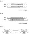
- the measurement gap refers to a section in which communication needs to be stopped in order to perform measurement.
- 6 subframe sections are provided as measurement gaps in each cell group.
- the user terminal applies the measurement gap pattern for synchronous dual connectivity according to the transmission timing difference observed at a specific event, and then performs asynchronous dual connection only once according to the observed transmission timing difference. You may switch to the measurement gap pattern for connectivity (see FIG. 6C).
- the user terminal may not switch to the measurement gap pattern for synchronous dual connectivity even if the transmission timing difference fluctuates. Good (see FIG. 6C).
- the user terminal can use any one or a combination of the following as a determination index for applying either synchronous dual connectivity control such as transmission power control or measurement gap pattern or asynchronous dual connectivity control.
- the user terminal can use the uplink transmission timing difference of any serving cell belonging to each cell group as a determination index. For example, the user terminal performs either synchronous dual connectivity control or asynchronous dual connectivity control based on whether or not the uplink transmission timing difference between any serving cells is within a predetermined value (for example, 33 + ⁇ [ ⁇ s]). You may decide whether to apply.
- a predetermined value for example, 33 + ⁇ [ ⁇ s]
- the user terminal can use the maximum uplink transmission timing difference of serving cells belonging to each cell group as a determination index. For example, the user terminal performs control for synchronous dual connectivity and control for asynchronous dual connectivity based on whether or not the transmission timing difference between cells with the largest uplink transmission timing difference is within a predetermined value (for example, 33 + ⁇ [ ⁇ s]). It may be determined whether any of the above is applied.
- a predetermined value for example, 33 + ⁇ [ ⁇ s]
- the user terminal can use the minimum uplink transmission timing difference of serving cells belonging to each cell group as a determination index. For example, the user terminal performs control for synchronous dual connectivity and control for asynchronous dual connectivity based on whether or not the transmission timing difference between cells with the smallest uplink transmission timing difference is within a predetermined value (for example, 33 + ⁇ [ ⁇ s]). It may be determined whether any of the above is applied.
- a predetermined value for example, 33 + ⁇ [ ⁇ s]
- the user terminal can use the uplink transmission timing difference between the PCell belonging to the master cell group and the PSCell belonging to the secondary cell group as a determination index. For example, the user terminal performs control for synchronous dual connectivity and asynchronous dual based on whether or not the transmission timing difference between the PCell belonging to the master cell group and the PSCell belonging to the secondary cell group is within a predetermined value (for example, 33 + ⁇ [ ⁇ s]). It may be determined whether to apply one of the connectivity controls.
- a predetermined value for example, 33 + ⁇ [ ⁇ s]
- the user terminal can use the downlink reception timing difference of an arbitrary serving cell belonging to each cell group as a determination index. For example, the user terminal determines whether to apply synchronous dual connectivity control or asynchronous dual connectivity control based on whether or not the downlink reception timing difference between any serving cells is within 33 [ ⁇ s]. Also good.
- the user terminal can use the maximum downlink reception timing difference between serving cells belonging to each cell group as a determination index. For example, the user terminal applies either synchronous dual connectivity control or asynchronous dual connectivity control based on whether or not the reception timing difference between cells with the largest downlink reception timing difference is within 33 [ ⁇ s]. You may judge.
- the user terminal can use the minimum downlink reception timing difference between serving cells belonging to each cell group as a determination index. For example, the user terminal applies either synchronous dual connectivity control or asynchronous dual connectivity control based on whether or not the reception timing difference between cells with the smallest downlink reception timing difference is within 33 [ ⁇ s]. You may judge.
- the user terminal can use the downlink reception timing difference between the PCell belonging to the master cell group and the PSCell belonging to the secondary cell group as a determination index. For example, based on whether the reception timing difference between the PCell belonging to the master cell group and the PSCell belonging to the secondary cell group is within 33 [ ⁇ s], the user terminal performs either synchronous dual connectivity control or asynchronous dual connectivity control. It may be determined whether to apply.
- the user terminal determines a predetermined determination such as a reception timing difference or a transmission timing difference. Based on the condition, it is determined whether it is synchronous dual connectivity or asynchronous dual connectivity.
- the user terminal determines that it is synchronous dual connectivity at a predetermined event, it performs control for synchronous dual connectivity such as transmission power control and measurement control. Thereafter, when the determination condition of the synchronous dual connectivity is deviated, the user terminal can switch to the control for asynchronous dual connectivity.
- the user terminal determines asynchronous dual connectivity at a predetermined event, it performs control for asynchronous dual connectivity. Thereafter, even if the asynchronous dual connectivity determination condition is deviated, the user terminal can be prevented from switching to the control for synchronous dual connectivity unless a predetermined event occurs again.
- the user terminal Once the user terminal has applied control for asynchronous dual connectivity, it can continue to perform control for asynchronous dual connectivity unless a predetermined event occurs again.
- Stopping control for synchronous dual connectivity refers to, for example, stopping uplink transmission of a secondary cell group. In this case, by making the user terminal autonomous state transition only in one direction (see FIG. 7), the ping-pong problem can be avoided and the battery consumption can be suppressed.
- the user terminal stops the control for synchronous dual connectivity when the transmission timing difference to be observed exceeds a predetermined value (for example, 33 + ⁇ [ ⁇ s]) in a state where the control for synchronous dual connectivity is applied.
- a predetermined value for example, 33 + ⁇ [ ⁇ s]
- the user terminal observes the transmission timing difference again, and if the observed transmission timing difference is within a predetermined value (for example, 33 + ⁇ [ ⁇ s]), applies the control for synchronous dual connectivity and observes If the transmission timing difference exceeds a predetermined value (for example, 33 + ⁇ [ ⁇ s]), the control for synchronous dual connectivity is not started.
- a predetermined value for example, 33 + ⁇ [ ⁇ s]
- a user terminal When a user terminal that supports only synchronous dual connectivity enters the asynchronous region, it may detect a radio link failure (RLF) in the secondary cell group, or start the reconnection procedure.
- RLF radio link failure
- the dedicated resources (PUCCH or SRS) of the SCell of the secondary cell group may be released, or all the TA timers of the sTAG of the secondary cell group may be forcibly expired or stopped.
- FIG. 8 is a schematic configuration diagram showing an example of a radio communication system according to the present embodiment.
- the radio communication system 1 is in a cell formed by a plurality of radio base stations 10 (11 and 12) and each radio base station 10, and is configured to be able to communicate with each radio base station 10.
- Each of the radio base stations 10 is connected to the higher station apparatus 30 and connected to the core network 40 via the higher station apparatus 30.
- the radio base station 11 is composed of, for example, a macro base station having a relatively wide coverage, and forms a macro cell C1.
- the radio base station 12 is configured by a small base station having local coverage, and forms a small cell C2.
- the number of radio base stations 11 and 12 is not limited to the number shown in FIG.
- the same frequency band may be used, or different frequency bands may be used.
- the radio base stations 11 and 12 are connected to each other via an inter-base station interface (for example, optical fiber, X2 interface).
- the user terminal 20 is a terminal that supports various communication methods such as LTE and LTE-A, and may include not only a mobile communication terminal but also a fixed communication terminal.
- the user terminal 20 can execute communication with other user terminals 20 via the radio base station 10.
- the upper station apparatus 30 includes, for example, an access gateway apparatus, a radio network controller (RNC), a mobility management entity (MME), and the like, but is not limited thereto.
- RNC radio network controller
- MME mobility management entity
- a downlink shared channel (PDSCH: physical downlink shared channel) shared by each user terminal 20, a downlink control channel (PDCCH: Physical downlink control channel, EPDCCH: enhanced physical downlink control channel).
- PDSCH physical downlink shared channel
- PDCCH Physical downlink control channel
- EPDCCH enhanced physical downlink control channel
- PBCH physical broadcast channel
- DCI downlink control information
- an uplink shared channel (PUSCH: physical uplink shared channel) shared by each user terminal 20, an uplink control channel (PUCCH: physical uplink control channel), or the like is used as an uplink channel.
- PUSCH physical uplink shared channel
- PUCCH physical uplink control channel
- FIG. 9 is an overall configuration diagram of the radio base station 10 according to the present embodiment.
- the radio base station 10 includes a plurality of transmission / reception antennas 101 for MIMO (multiple-input and multiple-output) transmission, an amplifier unit 102, a transmission / reception unit (transmission unit and reception unit) 103, A baseband signal processing unit 104, a call processing unit 105, and an interface unit 106.
- MIMO multiple-input and multiple-output
- User data transmitted from the radio base station 10 to the user terminal 20 via the downlink is input from the higher station apparatus 30 to the baseband signal processing unit 104 via the interface unit 106.
- PDCP packet data convergence protocol
- RLC radio link control
- MAC medium access control
- HARQ hybrid automatic repeat request
- IFFT inverse fast fourier transform
- precoding processing is performed for each transmission / reception Transferred to the unit 103.
- the downlink control signal is also subjected to transmission processing such as channel coding and inverse fast Fourier transform, and is transferred to each transmitting / receiving unit 103.
- Each transmission / reception unit 103 converts the downlink signal output from the baseband signal processing unit 104 by precoding for each antenna to a radio frequency band.
- the amplifier unit 102 amplifies the frequency-converted radio frequency signal and transmits the amplified signal using the transmission / reception antenna 101.
- the transmitter / receiver 103, a transmitter / receiver, a transmitter / receiver circuit, or a transmitter / receiver described based on common recognition in the technical field according to the present invention can be applied.
- the radio frequency signal received by each transmitting / receiving antenna 101 is amplified by the amplifier unit 102, frequency-converted by each transmitting / receiving unit 103, converted into a baseband signal, and sent to the baseband signal processing unit 104. Entered.
- the baseband signal processing unit 104 performs fast Fourier transform (FFT) processing, inverse discrete Fourier transform (IDFT) processing, and error correction on user data included in the input upstream signal. Decoding, MAC retransmission control reception processing, RLC layer, and PDCP layer reception processing are performed and transferred to the upper station apparatus 30 via the interface unit 106.
- the call processing unit 105 performs call processing such as communication channel setting and release, state management of the radio base station 10, and radio resource management.
- the interface unit 106 transmits / receives a signal (backhaul signaling) to / from an adjacent radio base station via an inter-base station interface (for example, optical fiber, X2 interface). Alternatively, the interface unit 106 transmits and receives signals to and from the higher station apparatus 30 via a predetermined interface.
- a signal backhaul signaling
- inter-base station interface for example, optical fiber, X2 interface
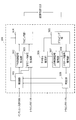
- FIG. 10 is a main functional configuration diagram of the baseband signal processing unit 104 included in the radio base station 10 according to the present embodiment.
- the baseband signal processing unit 104 included in the radio base station 10 includes a control unit 301, a downlink control signal generation unit 302, a downlink data signal generation unit 303, a mapping unit 304, and a demapping unit. 305, a channel estimation unit 306, an uplink control signal decoding unit 307, an uplink data signal decoding unit 308, and a determination unit 309 are included.
- the control unit 301 controls scheduling of downlink user data transmitted on the PDSCH, downlink control information transmitted on both or either of the PDCCH and the extended PDCCH (EPDCCH), downlink reference signals, and the like. In addition, the control unit 301 also performs scheduling control (allocation control) of RA preambles transmitted on the PRACH, uplink data transmitted on the PUSCH, uplink control information transmitted on the PUCCH or PUSCH, and uplink reference signals. Information related to allocation control of uplink signals (uplink control signals, uplink user data) is notified to the user terminal 20 using downlink control signals (DCI).
- DCI downlink control signals
- the control unit 301 controls allocation of radio resources to the downlink signal and the uplink signal based on the instruction information from the higher station apparatus 30 and the feedback information from each user terminal 20. That is, the control unit 301 has a function as a scheduler. A controller, a control circuit, or a control device described based on common recognition in the technical field according to the present invention can be applied to the control unit 301.
- the downlink control signal generation unit 302 generates a downlink control signal (both PDCCH signal and EPDCCH signal or one of them) whose assignment is determined by the control unit 301. Specifically, the downlink control signal generation unit 302 receives a downlink assignment for notifying downlink signal allocation information and an uplink grant for notifying uplink signal allocation information based on an instruction from the control unit 301. Generate. A signal generator or a signal generation circuit described based on common recognition in the technical field according to the present invention can be applied to the downlink control signal generation unit 302.
- the downlink data signal generation unit 303 generates a downlink data signal (PDSCH signal) determined to be allocated to resources by the control unit 301.
- the data signal generated by the downlink data signal generation unit 303 is subjected to an encoding process and a modulation process according to an encoding rate and a modulation scheme determined based on CSI from each user terminal 20 or the like.
- the mapping unit 304 allocates the downlink control signal generated by the downlink control signal generation unit 302 and the downlink data signal generated by the downlink data signal generation unit 303 to radio resources. Control.
- a mapping circuit or mapper described based on common recognition in the technical field according to the present invention can be applied to the mapping unit 304.
- the demapping unit 305 demaps the uplink signal transmitted from the user terminal 20 and separates the uplink signal.
- Channel estimation section 306 estimates the channel state from the reference signal included in the received signal separated by demapping section 305, and outputs the estimated channel state to uplink control signal decoding section 307 and uplink data signal decoding section 308.
- the uplink control signal decoding unit 307 decodes a feedback signal (such as a delivery confirmation signal) transmitted from the user terminal through the uplink control channel (PRACH, PUCCH) and outputs the decoded signal to the control unit 301.
- Uplink data signal decoding section 308 decodes the uplink data signal transmitted from the user terminal through the uplink shared channel (PUSCH), and outputs the decoded signal to determination section 309.
- the determination unit 309 performs retransmission control determination (A / N determination) based on the decoding result of the uplink data signal decoding unit 308 and outputs the result to the control unit 301.
- FIG. 11 is an overall configuration diagram of the user terminal 20 according to the present embodiment.
- the user terminal 20 includes a plurality of transmission / reception antennas 201 for MIMO transmission, an amplifier unit 202, a transmission / reception unit (transmission unit and reception unit) 203, a baseband signal processing unit 204, an application Unit 205.
- radio frequency signals received by a plurality of transmission / reception antennas 201 are each amplified by an amplifier unit 202, converted in frequency by a transmission / reception unit 203, and converted into a baseband signal.
- the baseband signal is subjected to FFT processing, error correction decoding, retransmission control reception processing, and the like by the baseband signal processing unit 204.
- downlink user data is transferred to the application unit 205.
- the application unit 205 performs processing related to layers higher than the physical layer and the MAC layer.
- broadcast information in the downlink data is also transferred to the application unit 205.
- the transmitter / receiver 203 may be a transmitter / receiver, a transmitter / receiver circuit, or a transmitter / receiver described based on common recognition in the technical field according to the present invention.
- uplink user data is input from the application unit 205 to the baseband signal processing unit 204.
- the baseband signal processing unit 204 performs retransmission control (HARQ) transmission processing, channel coding, precoding, discrete Fourier transform (DFT) processing, inverse fast Fourier transform (IFFT) processing, and the like, and performs transmission and reception units 203.
- HARQ retransmission control
- DFT discrete Fourier transform
- IFFT inverse fast Fourier transform
- the transmission / reception unit 203 converts the baseband signal output from the baseband signal processing unit 204 into a radio frequency band.
- the amplifier unit 202 amplifies the frequency-converted radio frequency signal and transmits the amplified signal using the transmission / reception antenna 201.
- FIG. 12 is a main functional configuration diagram of the baseband signal processing unit 204 included in the user terminal 20.
- the baseband signal processing unit 204 included in the user terminal 20 includes a control unit 401, an uplink control signal generation unit 402, an uplink data signal generation unit 403, a mapping unit 404, and a demapping unit 405.
- the control unit 401 determines the uplink control signal (A / N signal, etc.) and the uplink data signal. Control generation.
- the downlink control signal received from the radio base station is output from the downlink control signal decoding unit 407, and the retransmission control determination result is output from the determination unit 409.
- a controller, a control circuit, or a control device described based on common recognition in the technical field according to the present invention is applied to the control unit 401.
- the control unit 401 changes the other dual connectivity. Either the control not switching to the control for the control or the control switching to the other dual connectivity control is performed only for a predetermined number of times.
- the uplink control signal generation unit 402 generates an uplink control signal (feedback signal such as a delivery confirmation signal or channel state information (CSI)) based on an instruction from the control unit 401.
- Uplink data signal generation section 403 generates an uplink data signal based on an instruction from control section 401.
- the control unit 401 instructs the uplink data signal generation unit 403 to generate an uplink data signal when the downlink grant is included in the downlink control signal notified from the radio base station.
- a signal generator or a signal generation circuit described based on common recognition in the technical field according to the present invention can be applied to the uplink control signal generation unit 402.
- the mapping unit 404 controls allocation of uplink control signals (delivery confirmation signals and the like) and uplink data signals to radio resources (PUCCH, PUSCH) based on an instruction from the control unit 401.
- the demapping unit 405 demaps the downlink signal transmitted from the radio base station 10 and separates the downlink signal.
- Channel estimation section 406 estimates the channel state from the reference signal included in the received signal separated by demapping section 405, and outputs the estimated channel state to downlink control signal decoding section 407 and downlink data signal decoding section 408.
- the downlink control signal decoding unit 407 decodes the downlink control signal (PDCCH signal) transmitted on the downlink control channel (PDCCH), and outputs scheduling information (allocation information to uplink resources) to the control unit 401.
- the downlink control signal includes information on a cell that feeds back a delivery confirmation signal and information on whether or not RF adjustment is applied, the downlink control signal is also output to the control unit 401.
- the downlink data signal decoding unit 408 decodes the downlink data signal transmitted through the downlink shared channel (PDSCH), and outputs the decoded signal to the determination unit 409.
- the determination unit 409 performs retransmission control determination (A / N determination) based on the decoding result of the downlink data signal decoding unit 408 and outputs the result to the control unit 401.
Abstract
Description
LTE-Aシステムでは、半径数キロメートル程度の広範囲のカバレッジエリアを有するマクロセル内に、半径数十メートル程度の局所的なカバレッジエリアを有するスモールセルが形成されるHetNet(heterogeneous network)が検討されている。キャリアアグリゲーションおよびデュアルコネクティビティは、HetNet構成に適用することが可能である。 Hereinafter, embodiments of the present invention will be described in detail with reference to the drawings.
In the LTE-A system, a HetNet (heterogeneous network) in which a small cell having a local coverage area with a radius of several tens of meters is formed in a macro cell having a wide coverage area with a radius of several kilometers is being studied. . Carrier aggregation and dual connectivity can be applied to HetNet configurations.
ユーザ端末は、上位レイヤにおける特定のイベントが発生した場合、次のイベントが発生するまでの間、自端末の観測する送信タイミング差に基づいて同期デュアルコネクティビティ向け送信電力制御または非同期デュアルコネクティビティ向け送信電力制御を適用する。上位レイヤにおける特定のイベントには、たとえば、デュアルコネクティビティの設定(configure)が該当する。次のイベントには、たとえば、デュアルコネクティビティの再設定(re-configure)が該当する。 (First aspect)
When a specific event occurs in the upper layer, the user terminal controls transmission power for synchronous dual connectivity or transmission power for asynchronous dual connectivity based on the transmission timing difference observed by the user terminal until the next event occurs. Apply control. The specific event in the upper layer corresponds to, for example, dual connectivity configuration (configure). The next event corresponds to, for example, dual connectivity reconfiguration.
ユーザ端末が、同期デュアルコネクティビティのみに対応している場合の制御について説明する。 (Second aspect)
The control when the user terminal supports only synchronous dual connectivity will be described.
以下、本実施の形態に係る無線通信システムの構成について説明する。この無線通信システムでは、上述の制御を行う無線通信方法が適用される。 (Configuration of wireless communication system)
Hereinafter, the configuration of the wireless communication system according to the present embodiment will be described. In this wireless communication system, the wireless communication method for performing the above-described control is applied.
Claims (10)
- 異なる周波数を利用する1つ以上のセルからそれぞれ構成される複数のセルグループと通信を行うユーザ端末であって、
上位レイヤにおけるイベントが発生した時点の指標に基づいて同期デュアルコネクティビティ向け制御および非同期デュアルコネクティビティ向け制御のいずれかを適用している状態で前記指標が変動した場合に、他方のデュアルコネクティビティ用制御に切り替えない制御および所定回数に限り他方のデュアルコネクティビティ用制御に切り替える制御のいずれかをする制御部を有することを特徴とするユーザ端末。 A user terminal that communicates with a plurality of cell groups each composed of one or more cells using different frequencies,
Switch to the other dual connectivity control when the index changes while applying either synchronous dual connectivity control or asynchronous dual connectivity control based on the index at the time of the event in the upper layer A user terminal comprising: a control unit that performs any one of a non-control and a control for switching to the other dual connectivity control only a predetermined number of times. - 前記制御部は、前記非同期デュアルコネクティビティ向け制御を適用している状態で前記指標が変動した場合に、前記同期デュアルコネクティビティ向け制御に切り替えない制御および前記同期デュアルコネクティビティ向け制御を適用している状態で前記指標が変動した場合に、前記非同期デュアルコネクティビティ向け制御に切り替える制御のいずれかをすることを特徴とする請求項1に記載のユーザ端末。 In the state where the control is not switched to the control for the synchronous dual connectivity and the control for the synchronous dual connectivity is applied when the index is changed while the control for the asynchronous dual connectivity is applied. 2. The user terminal according to claim 1, wherein when the index fluctuates, the user terminal is controlled to switch to the asynchronous dual connectivity control. 3.
- 前記制御部は、前記同期デュアルコネクティビティ向け制御を適用している状態から前記非同期デュアルコネクティビティ向け制御に切り替えた後に再度前記指標が変動しても、前記同期デュアルコネクティビティ向け制御に切り替えないことを特徴とする請求項2に記載のユーザ端末。 The control unit does not switch to the synchronous dual connectivity control even if the index fluctuates again after switching to the asynchronous dual connectivity control from the state where the synchronous dual connectivity control is applied. The user terminal according to claim 2.
- 前記制御部は、前記非同期デュアルコネクティビティ向け制御を適用した場合、別のイベントが発生しない限り、前記同期デュアルコネクティビティ向け制御に切り替えないことを特徴とする請求項2に記載のユーザ端末。 The user terminal according to claim 2, wherein when the control for asynchronous dual connectivity is applied, the control unit does not switch to the control for synchronous dual connectivity unless another event occurs.
- 前記イベントは、デュアルコネクティビティの設定もしくは再設定、RRCパラメータ再設定、PSCellチェンジ、SCellチェンジ、セカンダリセルグループの変更またはSCellのアクティブ化もしくは非アクティブ化の少なくとも1つであることを特徴とする請求項1から請求項4のいずれかに記載のユーザ端末。 The event is at least one of dual connectivity setting or resetting, RRC parameter resetting, PSCell change, SCell change, secondary cell group change, or SCell activation or deactivation. The user terminal according to any one of claims 1 to 4.
- 前記指標は、各セルグループに属する任意のサービングセルの上りリンク送信タイミング差であることを特徴とする請求項1に記載のユーザ端末。 The user terminal according to claim 1, wherein the indicator is an uplink transmission timing difference of an arbitrary serving cell belonging to each cell group.
- 前記指標は、各セルグループに属する任意のサービングセルの下りリンク受信タイミング差であることを特徴とする請求項1に記載のユーザ端末。 The user terminal according to claim 1, wherein the index is a downlink reception timing difference of an arbitrary serving cell belonging to each cell group.
- 前記同期デュアルコネクティビティ向け制御は、送信電力制御またはメジャメント制御であることを特徴とする請求項1に記載のユーザ端末。 The user terminal according to claim 1, wherein the control for synchronous dual connectivity is transmission power control or measurement control.
- 異なる周波数を利用する1つ以上のセルからそれぞれ構成されるセルグループを形成し、前記セルグループと異なるセルグループを形成する他の無線基地局とデュアルコネクティビティを適用して無線基地局がユーザ端末と通信する無線通信システムであって、
前記ユーザ端末は、
上位レイヤにおけるイベントが発生した時点の指標に基づいて同期デュアルコネクティビティ向け制御および非同期デュアルコネクティビティ向け制御のいずれかを適用している状態で前記指標が変動した場合に、他方のデュアルコネクティビティ用制御に切り替えない制御および所定回数に限り他方のデュアルコネクティビティ用制御に切り替える制御のいずれかをする制御部を有することを特徴とする無線通信システム。 Forming cell groups each composed of one or more cells using different frequencies, and applying dual connectivity with other radio base stations forming a cell group different from the cell group, the radio base station and the user terminal A wireless communication system for communicating,
The user terminal is
Switch to the other dual connectivity control when the index changes while applying either synchronous dual connectivity control or asynchronous dual connectivity control based on the index at the time of the event in the upper layer A wireless communication system, comprising: a control unit that performs any one of a non-control and a control for switching to the other dual connectivity control only for a predetermined number of times. - 異なる周波数を利用する1つ以上のセルからそれぞれ構成される複数のセルグループと通信を行うユーザ端末の無線通信方法であって、
上位レイヤにおけるイベントが発生した時点の指標に基づいて同期デュアルコネクティビティ向け制御および非同期デュアルコネクティビティ向け制御のいずれかを適用している状態で前記指標が変動した場合に、他方のデュアルコネクティビティ用制御に切り替えない制御および所定回数に限り他方のデュアルコネクティビティ用制御に切り替える制御のいずれかをする工程を有することを特徴とする無線通信方法。
A wireless communication method for a user terminal that communicates with a plurality of cell groups each composed of one or more cells using different frequencies,
Switch to the other dual connectivity control when the index changes while applying either synchronous dual connectivity control or asynchronous dual connectivity control based on the index at the time of the event in the upper layer A wireless communication method comprising a step of performing any one of a non-control and a control for switching to the other dual connectivity control only for a predetermined number of times.
Priority Applications (4)
| Application Number | Priority Date | Filing Date | Title |
|---|---|---|---|
| JP2016550380A JP6343015B2 (en) | 2014-09-25 | 2015-09-25 | User terminal and wireless communication method |
| US15/513,777 US20170295568A1 (en) | 2014-09-25 | 2015-09-25 | User terminal, radio communication system and radio communication method |
| EP15845363.9A EP3200535A4 (en) | 2014-09-25 | 2015-09-25 | User terminal, wireless communication system, and wireless communication method |
| CN201580051254.9A CN106717093A (en) | 2014-09-25 | 2015-09-25 | User terminal, wireless communication system, and wireless communication method |
Applications Claiming Priority (2)
| Application Number | Priority Date | Filing Date | Title |
|---|---|---|---|
| JP2014195694 | 2014-09-25 | ||
| JP2014-195694 | 2014-09-25 |
Publications (1)
| Publication Number | Publication Date |
|---|---|
| WO2016047728A1 true WO2016047728A1 (en) | 2016-03-31 |
Family
ID=55581246
Family Applications (1)
| Application Number | Title | Priority Date | Filing Date |
|---|---|---|---|
| PCT/JP2015/077044 WO2016047728A1 (en) | 2014-09-25 | 2015-09-25 | User terminal, wireless communication system, and wireless communication method |
Country Status (5)
| Country | Link |
|---|---|
| US (1) | US20170295568A1 (en) |
| EP (1) | EP3200535A4 (en) |
| JP (1) | JP6343015B2 (en) |
| CN (1) | CN106717093A (en) |
| WO (1) | WO2016047728A1 (en) |
Cited By (2)
| Publication number | Priority date | Publication date | Assignee | Title |
|---|---|---|---|---|
| CN109792703A (en) * | 2016-09-30 | 2019-05-21 | 瑞典爱立信有限公司 | It is adapted between simultaneously operating and asynchronous operation based on parameter set |
| WO2022269919A1 (en) * | 2021-06-25 | 2022-12-29 | 株式会社Nttドコモ | Terminal, wireless communication method, and base station |
Families Citing this family (9)
| Publication number | Priority date | Publication date | Assignee | Title |
|---|---|---|---|---|
| US9801140B2 (en) * | 2014-02-11 | 2017-10-24 | Lg Electronics Inc. | Method and apparatus for controlling uplink power in wireless |
| WO2016080899A1 (en) * | 2014-11-18 | 2016-05-26 | Telefonaktiebolaget L M Ericsson (Publ) | Methods and apparatuses for determining unsynchronised or synchronised dual connectivity mode of a user equipment |
| US10264560B2 (en) * | 2014-12-31 | 2019-04-16 | Lg Electronics Inc. | Uplink signal transmitting method and user equipment, and uplink signal receiving method and base station |
| US11172389B2 (en) * | 2016-03-31 | 2021-11-09 | Intel Corporation | Measurement gap configuration |
| EP3860196A4 (en) * | 2018-09-27 | 2022-05-25 | Ntt Docomo, Inc. | User equipment |
| WO2020062059A1 (en) * | 2018-09-28 | 2020-04-02 | Oppo广东移动通信有限公司 | Method and device for processing link failure, terminal device and storage medium |
| US20210345271A1 (en) * | 2018-11-13 | 2021-11-04 | Ntt Docomo, Inc. | User equipment and base station apparatus |
| KR102469636B1 (en) * | 2019-01-02 | 2022-11-23 | 삼성전자 주식회사 | Apparatus and method for controlling transmission power of electronic device in a wireless communication system |
| US11419170B2 (en) * | 2019-04-02 | 2022-08-16 | Qualcomm Incorporated | Radio access technology ping-pong reselection and registration avoidance |
Family Cites Families (5)
| Publication number | Priority date | Publication date | Assignee | Title |
|---|---|---|---|---|
| US20120214540A1 (en) * | 2011-02-21 | 2012-08-23 | Motorola Mobility, Inc. | Signal Measurement on Component Carriers in Wireless Communication Systems |
| KR20130045169A (en) * | 2011-10-24 | 2013-05-03 | 주식회사 팬택 | Apparatus and method for performing uplink synchronization in multiple component carrier system |
| US9137717B2 (en) * | 2012-01-13 | 2015-09-15 | Qualcomm Incorporated | Method and apparatus for managing mobility events in a dual-frequency dual-cell wireless communication network |
| US8989128B2 (en) * | 2012-04-20 | 2015-03-24 | Ofinno Technologies, Llc | Cell timing in a wireless device and base station |
| US9801140B2 (en) * | 2014-02-11 | 2017-10-24 | Lg Electronics Inc. | Method and apparatus for controlling uplink power in wireless |
-
2015
- 2015-09-25 US US15/513,777 patent/US20170295568A1/en not_active Abandoned
- 2015-09-25 JP JP2016550380A patent/JP6343015B2/en active Active
- 2015-09-25 WO PCT/JP2015/077044 patent/WO2016047728A1/en active Application Filing
- 2015-09-25 EP EP15845363.9A patent/EP3200535A4/en not_active Withdrawn
- 2015-09-25 CN CN201580051254.9A patent/CN106717093A/en active Pending
Non-Patent Citations (3)
| Title |
|---|
| NTT DOCOMO, INC.: "Pcmax for Dual connectivity", 3GPP TSG-RAN WG4 MEETING #72 R4-144384, 11 August 2014 (2014-08-11), XP050825170, Retrieved from the Internet <URL:http://www.3gpp.org/ftp/tsg_ran/WG4_Radio/TSGR4_72/Docs/R4-144384.zip> [retrieved on 20151203] * |
| NTT DOCOMO: "LS on RANI agreements on Physical layer functionalities required for operation of Dual Connectivity", 3GPP TSG RAN WG1 MEETING #78 R1-143667, 25 August 2014 (2014-08-25), XP050815946, Retrieved from the Internet <URL:http://www.3gpp.org/ftp/tsg_ran/WG1_RL1/TSGR1_78/Docs/R1-143667.zip> [retrieved on 20151203] * |
| See also references of EP3200535A4 * |
Cited By (2)
| Publication number | Priority date | Publication date | Assignee | Title |
|---|---|---|---|---|
| CN109792703A (en) * | 2016-09-30 | 2019-05-21 | 瑞典爱立信有限公司 | It is adapted between simultaneously operating and asynchronous operation based on parameter set |
| WO2022269919A1 (en) * | 2021-06-25 | 2022-12-29 | 株式会社Nttドコモ | Terminal, wireless communication method, and base station |
Also Published As
| Publication number | Publication date |
|---|---|
| CN106717093A (en) | 2017-05-24 |
| JPWO2016047728A1 (en) | 2017-07-20 |
| US20170295568A1 (en) | 2017-10-12 |
| EP3200535A4 (en) | 2018-02-28 |
| EP3200535A1 (en) | 2017-08-02 |
| JP6343015B2 (en) | 2018-06-13 |
Similar Documents
| Publication | Publication Date | Title |
|---|---|---|
| JP6343015B2 (en) | User terminal and wireless communication method | |
| EP3096568B1 (en) | User terminal, radio base station, and radio communication method | |
| US9712308B2 (en) | Method for enhancing small cell | |
| EP3169117B1 (en) | User terminal, wireless communication system, and wireless communication method | |
| JP2020099057A (en) | System and method for srs switching, transmission, and extension | |
| JP2020036333A (en) | User terminal and radio communication method | |
| US10271315B2 (en) | User terminal, radio base station, radio communication system, and radio communication method | |
| US11147081B2 (en) | User terminal, radio base station, and radio communication method | |
| WO2015170725A1 (en) | User terminal, wireless base station, wireless communication method and wireless communication system | |
| JP6272483B2 (en) | User terminal and wireless communication method | |
| WO2014084111A1 (en) | Mobile station and control method | |
| US20170142668A1 (en) | User terminal, radio base station, radio communication system and radio communication method | |
| KR20160110889A (en) | Methods for transmitting channel state information and Apparatuses thereof | |
| WO2017135346A1 (en) | User terminal, wireless base station, and wireless communication method | |
| WO2016072215A1 (en) | User terminal, wireless base station, wireless communication system, and wireless communication method | |
| EP3917031B1 (en) | Method and apparatus for carrier aggregation communication in wireless communication system | |
| JP6400156B2 (en) | Cellular base station and method of operating it | |
| WO2015045960A1 (en) | User terminal and wireless communication method | |
| EP4170930A1 (en) | Method and apparatus for carrier aggregation communication in wireless communication system |
Legal Events
| Date | Code | Title | Description |
|---|---|---|---|
| 121 | Ep: the epo has been informed by wipo that ep was designated in this application |
Ref document number: 15845363 Country of ref document: EP Kind code of ref document: A1 |
|
| ENP | Entry into the national phase |
Ref document number: 2016550380 Country of ref document: JP Kind code of ref document: A |
|
| WWE | Wipo information: entry into national phase |
Ref document number: 15513777 Country of ref document: US |
|
| NENP | Non-entry into the national phase |
Ref country code: DE |
|
| REEP | Request for entry into the european phase |
Ref document number: 2015845363 Country of ref document: EP |
|
| WWE | Wipo information: entry into national phase |
Ref document number: 2015845363 Country of ref document: EP |