WO2016038951A1 - Holding state detection device - Google Patents
Holding state detection device Download PDFInfo
- Publication number
- WO2016038951A1 WO2016038951A1 PCT/JP2015/066350 JP2015066350W WO2016038951A1 WO 2016038951 A1 WO2016038951 A1 WO 2016038951A1 JP 2015066350 W JP2015066350 W JP 2015066350W WO 2016038951 A1 WO2016038951 A1 WO 2016038951A1
- Authority
- WO
- WIPO (PCT)
- Prior art keywords
- holding state
- state detection
- housing
- piezoelectric sensor
- detection device
- Prior art date
Links
- 238000001514 detection method Methods 0.000 title claims abstract description 261
- 239000004020 conductor Substances 0.000 claims abstract description 55
- 239000004626 polylactic acid Substances 0.000 claims description 24
- 229920000747 poly(lactic acid) Polymers 0.000 claims description 23
- 238000006073 displacement reaction Methods 0.000 abstract description 4
- 238000003825 pressing Methods 0.000 description 24
- 238000012423 maintenance Methods 0.000 description 19
- 230000001681 protective effect Effects 0.000 description 10
- 238000010586 diagram Methods 0.000 description 6
- 239000000463 material Substances 0.000 description 6
- 238000000034 method Methods 0.000 description 6
- 239000002033 PVDF binder Substances 0.000 description 5
- 239000000853 adhesive Substances 0.000 description 5
- 230000001070 adhesive effect Effects 0.000 description 5
- 229920002981 polyvinylidene fluoride Polymers 0.000 description 5
- 239000000758 substrate Substances 0.000 description 5
- XLYOFNOQVPJJNP-UHFFFAOYSA-N water Substances O XLYOFNOQVPJJNP-UHFFFAOYSA-N 0.000 description 5
- 238000005259 measurement Methods 0.000 description 3
- 229920000642 polymer Polymers 0.000 description 3
- 230000005616 pyroelectricity Effects 0.000 description 3
- 230000015572 biosynthetic process Effects 0.000 description 2
- 239000000919 ceramic Substances 0.000 description 2
- 230000006866 deterioration Effects 0.000 description 2
- 230000000694 effects Effects 0.000 description 2
- 238000010438 heat treatment Methods 0.000 description 2
- 239000012528 membrane Substances 0.000 description 2
- 230000003183 myoelectrical effect Effects 0.000 description 2
- NJPPVKZQTLUDBO-UHFFFAOYSA-N novaluron Chemical compound C1=C(Cl)C(OC(F)(F)C(OC(F)(F)F)F)=CC=C1NC(=O)NC(=O)C1=C(F)C=CC=C1F NJPPVKZQTLUDBO-UHFFFAOYSA-N 0.000 description 2
- 230000035945 sensitivity Effects 0.000 description 2
- 239000000654 additive Substances 0.000 description 1
- 230000000996 additive effect Effects 0.000 description 1
- 230000032683 aging Effects 0.000 description 1
- 239000002131 composite material Substances 0.000 description 1
- 230000008602 contraction Effects 0.000 description 1
- 239000013078 crystal Substances 0.000 description 1
- 238000002425 crystallisation Methods 0.000 description 1
- 230000008025 crystallization Effects 0.000 description 1
- 238000000354 decomposition reaction Methods 0.000 description 1
- 239000000284 extract Substances 0.000 description 1
- 239000011810 insulating material Substances 0.000 description 1
- 150000002500 ions Chemical class 0.000 description 1
- 238000012538 light obscuration Methods 0.000 description 1
- 238000002156 mixing Methods 0.000 description 1
- 230000002093 peripheral effect Effects 0.000 description 1
- 230000010287 polarization Effects 0.000 description 1
Images


Classifications
-
- G—PHYSICS
- G01—MEASURING; TESTING
- G01L—MEASURING FORCE, STRESS, TORQUE, WORK, MECHANICAL POWER, MECHANICAL EFFICIENCY, OR FLUID PRESSURE
- G01L1/00—Measuring force or stress, in general
- G01L1/16—Measuring force or stress, in general using properties of piezoelectric devices
-
- G—PHYSICS
- G01—MEASURING; TESTING
- G01L—MEASURING FORCE, STRESS, TORQUE, WORK, MECHANICAL POWER, MECHANICAL EFFICIENCY, OR FLUID PRESSURE
- G01L1/00—Measuring force or stress, in general
- G01L1/20—Measuring force or stress, in general by measuring variations in ohmic resistance of solid materials or of electrically-conductive fluids; by making use of electrokinetic cells, i.e. liquid-containing cells wherein an electrical potential is produced or varied upon the application of stress
- G01L1/22—Measuring force or stress, in general by measuring variations in ohmic resistance of solid materials or of electrically-conductive fluids; by making use of electrokinetic cells, i.e. liquid-containing cells wherein an electrical potential is produced or varied upon the application of stress using resistance strain gauges
- G01L1/2287—Measuring force or stress, in general by measuring variations in ohmic resistance of solid materials or of electrically-conductive fluids; by making use of electrokinetic cells, i.e. liquid-containing cells wherein an electrical potential is produced or varied upon the application of stress using resistance strain gauges constructional details of the strain gauges
-
- G—PHYSICS
- G06—COMPUTING; CALCULATING OR COUNTING
- G06F—ELECTRIC DIGITAL DATA PROCESSING
- G06F3/00—Input arrangements for transferring data to be processed into a form capable of being handled by the computer; Output arrangements for transferring data from processing unit to output unit, e.g. interface arrangements
- G06F3/01—Input arrangements or combined input and output arrangements for interaction between user and computer
- G06F3/03—Arrangements for converting the position or the displacement of a member into a coded form
- G06F3/033—Pointing devices displaced or positioned by the user, e.g. mice, trackballs, pens or joysticks; Accessories therefor
- G06F3/0354—Pointing devices displaced or positioned by the user, e.g. mice, trackballs, pens or joysticks; Accessories therefor with detection of 2D relative movements between the device, or an operating part thereof, and a plane or surface, e.g. 2D mice, trackballs, pens or pucks
- G06F3/03545—Pens or stylus
Definitions
- the present invention relates to a holding state detection device that detects that a person is holding an object to be detected.
- an electronic writing instrument described in Patent Literature 1 includes a tact switch disposed in a housing and an operation button that projects outside the housing.
- the bottom of the operation button pushes the tact switch.
- the tact switch is turned on by this depression. Thereby, it is detected that the operator has operated the electronic writing instrument.
- an object of the present invention is to provide a highly reliable holding state detection device that can detect a holding state without making the operator aware of it.
- the holding state detection device detects a holding state of a housing using a housing that can be held by an operator, a piezoelectric sensor mounted on the housing, and a variation amount of an output voltage of the piezoelectric sensor. And a detecting unit.
- the piezoelectric sensor includes a flat film piezoelectric film and a conductor film that extracts charges generated by the piezoelectric film.
- the piezoelectric sensor can be made thin and can be easily attached to the housing.
- the piezoelectric film preferably contains polylactic acid as a main component and is stretched in a uniaxial direction.
- the holding state can be accurately detected without being affected by pyroelectricity.
- the casing is cylindrical or box-shaped, and the piezoelectric sensor is mounted on the inner wall surface of the casing.
- the operator does not directly touch the piezoelectric sensor, and the holding state can be accurately detected.
- the detection unit identifies that the casing is held when detecting that the fluctuation amount is larger than a preset threshold value.
- the detection unit identifies that the holding of the housing has been released when it is detected that the fluctuation amount is equal to or less than the threshold value after the fluctuation amount is greater than the threshold value. Is preferred.
- the detection unit may perform start control of the operation executed by the holding state detection device when detecting that the output voltage is larger than a preset operation control threshold.
- the detection unit detects that the output voltage is larger than the preset first operation control threshold, and the subsequent output voltage is set higher than the preset second operation control threshold. If it is detected that the value is smaller, control for starting the operation executed by the holding state detection device may be performed.
- the holding state detection device of the present invention may have the following configuration.
- the detection unit detects a time when the output voltage becomes maximum, detects a time when the output voltage thereafter becomes minimum, and calculates these time intervals.
- the detection unit detects that the time interval is longer than the time threshold for operation control, the detection unit performs start control of the operation executed by the holding state detection device.
- FIG. 1A is a perspective view of a holding state detection apparatus according to the first embodiment of the present invention.
- FIG. 1B is a cross-sectional view of the holding state detection device according to the first embodiment of the present invention.
- FIG. 1B is a cross-sectional view of a region where the piezoelectric sensor is mounted in the holding state detection device.
- FIG. 2 is a functional block diagram of the holding state detection apparatus according to the first embodiment of the present invention.
- a holding state detection device having the shape of an electronic writing instrument will be described as an example.
- the holding state detection device 10 includes a piezoelectric sensor 20 and a housing 101.
- the holding state detection device 10 includes a piezoelectric sensor 20 and a detection unit 30.
- the piezoelectric sensor 20 and the detection unit 30 are connected.
- the detection unit 30 detects the output voltage of the piezoelectric sensor 20 and detects whether or not the casing 101 is held by the operator.
- the detection unit 30 may be mounted inside the housing 101 or may be disposed outside the housing 101. In an embodiment in which the piezoelectric sensor 20 and the detection unit 30 are arranged outside the housing 101, the piezoelectric sensor 20 and the detection unit 30 may be connected by wire or wirelessly.
- the housing 101 is cylindrical and has a hollow shape.
- the casing 101 is made of an insulating material.
- a tapered end 102 is provided at one end of the casing 101 in the longitudinal direction (direction orthogonal to the circumferential direction).
- the operator When using the holding state detection device 10 as an electronic writing instrument, the operator handles the holding state detection device 10 as follows. The operator holds the cylindrical portion of the housing 101 and brings the tapered end portion 102 into contact with another electronic device (for example, an electronic blackboard). When the operator moves the holding state detection device 10, the tip end portion of the tapered end portion 102 also moves. Other electronic devices accept the operation input of the operator by sensing this movement.
- another electronic device for example, an electronic blackboard
- the piezoelectric sensor 20 is a flexible flat film, and is disposed on the inner wall of the housing 101 as shown in FIG. At this time, the piezoelectric sensor 20 is arranged along the circumferential direction on the inner wall surface.
- the piezoelectric sensor 20 includes a flat film piezoelectric film and a detection conductor.
- the detection conductor is formed on two opposing flat membrane surfaces of the piezoelectric film.
- the detection conductor is connected to the detection unit 30.
- Piezoelectric film is a piezoelectric material that generates electric charges on opposing flat membrane surfaces by expansion and contraction.
- the piezoelectric film is uniaxially stretched polylactic acid (PLA), more specifically L-type polylactic acid (PLLA).
- the uniaxial stretching direction of polylactic acid is a direction that forms approximately 45 ° with respect to the longitudinal direction of the piezoelectric film. The angle formed is most preferably 45 °, but may be within a range of about ⁇ 10 °.
- the longitudinal direction of the piezoelectric film is a circumferential direction along the inner wall of the housing 101 in the example of FIG.
- PLLA consists of a chiral polymer.
- PLLA has a helical structure in the main chain.
- molecules are oriented in a uniaxially stretched direction, and have piezoelectricity due to the orientation of the molecules.
- the uniaxially-stretched PLLA generates electric charges when the piezoelectric film expands. The amount of charge generated is determined by the amount of expansion of the piezoelectric film.
- the piezoelectric constant of uniaxially stretched PLLA belongs to a very high class among polymers.
- the piezoelectric strain constant d 14 of PLLA can be as high as 10 to 20 pC / N by adjusting conditions such as stretching conditions, heat treatment conditions, and additive blending.
- the stretching ratio of the piezoelectric film is preferably about 3 to 8 times.
- the stretching ratio of the piezoelectric film is preferably about 3 to 8 times.
- PLLA generates piezoelectricity by molecular orientation treatment such as stretching, and therefore does not need to be subjected to poling treatment like other polymers such as PVDF and piezoelectric ceramics. That is, the piezoelectricity of PLLA that does not belong to ferroelectrics is not expressed by the polarization of ions like ferroelectrics such as PVDF and PZT, but is derived from a helical structure that is a characteristic structure of molecules. is there. For this reason, the pyroelectricity generated in other ferroelectric piezoelectric materials does not occur in PLLA.
- PVDF or the like shows a change in piezoelectric constant over time, and in some cases, the piezoelectric constant may be significantly reduced, but the piezoelectric constant of PLLA is extremely stable over time. Therefore, the output charge amount is not affected by the length of use time or the surrounding environment.
- FIG. 3 is a graph showing the output voltage of the piezoelectric sensor of the holding state detection device according to the first embodiment of the present invention. As shown in FIG. 3, during the period when the housing 101 is not held, there is almost no voltage fluctuation and the fluctuation amount is extremely small. On the other hand, during the period in which the housing 101 is held, the voltage fluctuates greatly and the fluctuation amount is large.
- FIG. 4 is a flowchart showing a holding detection flow in the holding state detection apparatus according to the first embodiment of the present invention.
- the detection unit 30 observes the output voltage of the piezoelectric sensor 20 (S101).
- the detection unit 30 calculates a fluctuation amount of the output voltage per preset measurement unit time (S102).
- the fluctuation amount is, for example, a difference between the maximum voltage and the minimum voltage within the measurement unit time.
- the detection unit 30 compares the fluctuation amount with a threshold voltage (holding detection threshold) Vw.
- a threshold voltage holding detection threshold
- Vw threshold voltage
- the detection unit 30 identifies that the housing 101 is being held (lifted) (S104). If the fluctuation amount is equal to or lower than the threshold voltage Vw (S103: NO), the detection unit 30 identifies that the housing 101 is not held. Then, the detection unit 30 continuously measures the output voltage, calculates the fluctuation amount for each unit time, and compares it with the threshold value.
- the holding state detection device 10 can detect that the casing 101 is held.
- FIG. 5 is a flowchart showing a holding state detection flow in the holding state detection apparatus according to the first embodiment of the present invention. Note that the steps up to step S104 of holding detection in FIG.
- the detection unit 30 continues the comparison between the variation amount and the threshold value Vw, and continues to identify that the casing 101 is held in a period (S105: NO) in which the variation amount does not become the threshold value Vw or less.
- the detecting unit 30 When the detecting unit 30 detects that the fluctuation amount is equal to or less than the threshold value Vw (S105: YES), it starts measuring time.
- the detection unit 30 measures, as an elapsed time, a time during which the state in which the variation amount is equal to or less than the threshold value Vw continues with reference to the timing at which the variation amount is detected as the threshold value Vw or less.
- the detection unit 30 continues to identify that the casing 101 is held in a period (S106: NO) in which the elapsed time is shorter than the threshold time.
- the detection unit 30 identifies that the holding (lifting) of the casing 101 is released (S107).
- the detection unit 30 can detect the holding state of the casing 101 (whether or not it is held).
- the detection unit 30 may set the difference between the maximum voltage or the minimum voltage within the measurement unit time and the reference voltage as the variation amount, with the average voltage in the non-holding period (initial state) as the reference voltage.
- the threshold value Va in FIG. 3 defined by the potential difference from the reference voltage may be used.
- the mode in which the piezoelectric sensor 20 is mounted in the vicinity of the connection portion between the housing 101 and the tapered end portion 102 is shown.
- the piezoelectric sensor 20 may be mounted at another position of the housing 101.
- the holding state can be detected more accurately and reliably by mounting the piezoelectric sensor 20 at a position that is most easily gripped by the operator.
- FIG. 6 is a perspective view of a holding state detection apparatus according to the second embodiment of the present invention.
- the holding state detection device 10A according to the present embodiment is different from the holding state detection device 10 according to the first embodiment in the shape of the piezoelectric sensor 20A and the mounting mode with respect to the housing 101. Other configurations are the same as those of the holding state detection apparatus 10 according to the first embodiment.
- the piezoelectric sensor 20A has a shape that extends not only over the entire circumference of the casing 101 but also in the longitudinal direction of the casing 101. With such a configuration, the holding state can be accurately and reliably detected without being affected by the gripping position of the housing 101.
- FIG. 7 is a perspective view of a holding state detection apparatus according to the third embodiment of the present invention.
- the holding state detection device 10B according to the present embodiment is different from the holding state detection device 10 according to the first embodiment in the shape of the piezoelectric sensor 20B and the mounting mode with respect to the housing 101. Other configurations are the same as those of the holding state detection apparatus 10 according to the first embodiment.
- the piezoelectric sensor 20B is mounted on the casing 101 so that the longitudinal direction of the casing 101 and the longitudinal direction of the piezoelectric sensor 20B are parallel to each other. Even with such a configuration, as in the first and second embodiments, the holding state can be accurately and reliably detected. Furthermore, by using the configuration of the present embodiment, the holding state can be detected without being affected by the gripping position, and the area of the piezoelectric film can be reduced. Thereby, it is cheap and it is easy to affix the piezoelectric sensor 20B to the housing 101.
- FIG. 8 is a perspective view of a holding state detection apparatus according to the fourth embodiment of the present invention.
- the holding state detection device 10C according to the present embodiment is different from the holding state detection device 10 according to the first embodiment in the shape of the piezoelectric sensor 20C and the mounting mode with respect to the housing 101. Other configurations are the same as those of the holding state detection apparatus 10 according to the first embodiment.
- the piezoelectric sensor 20C is long.
- the piezoelectric sensor 20 ⁇ / b> C is spirally attached along the circumferential surface of the housing 101.
- the uniaxial stretching direction of the piezoelectric film is preferably parallel to a long direction of the piezoelectric sensor 20C or a short length orthogonal to the long direction.
- the holding state can be accurately and reliably detected without being affected by the gripping position, as in the second embodiment. Furthermore, in the configuration of the present embodiment, the area of the piezoelectric film can be reduced.
- FIG. 9 is a side view showing a state in which the piezoelectric film is mounted on the piezoelectric film mounting jig used in the holding state detection apparatus according to the fifth embodiment of the present invention.
- the basic structure of the holding state detection device according to the present embodiment is the same as that of the holding state detection device according to the first embodiment, and the mounting structure of the piezoelectric sensor 20 is different.
- the piezoelectric sensor 20 is affixed to the surface of the mounting jig 40 having high elasticity.
- the mounting jig 40 has a curved shape according to the shape of the inner wall surface of the housing 101.
- the piezoelectric sensor 20 is affixed to the outer peripheral surface of the mounting jig 40.
- the mounting jig 40 When mounting the piezoelectric sensor 20 inside the housing 101, the mounting jig 40 is inserted into the housing 101 in a state of being bent from a steady state. The inserted mounting jig 40 presses the piezoelectric sensor 20 in a direction toward the inner wall surface of the housing 101 in an attempt to return to the steady state. As a result, the piezoelectric sensor 20 can be held in a state of being in contact with the inner wall surface of the housing 101.
- FIG. 10 is an exploded perspective view showing the configuration of the piezoelectric sensor and the detection unit in the holding state detection device according to the sixth embodiment of the present invention.
- FIG. 11 is a side cross-sectional view in an exploded state showing a configuration of a piezoelectric sensor and a detection unit in a holding state detection apparatus according to a sixth embodiment of the present invention.
- the holding state detection device 10D includes a piezoelectric sensor 20D and a detection unit 30D.
- the function of the piezoelectric sensor 20D is the same as the function of the piezoelectric sensor 20 according to the first embodiment.
- the function of the detection unit 30D is the same as that of the detection unit 30 according to the first embodiment.
- the piezoelectric sensor 20D includes a base film 201, a detection conductor 202, a piezoelectric sheet 203, a first ground conductor 204, a second ground conductor 205, and protective films 206 and 207.
- the base film 201 has insulating properties and is made of, for example, PET.
- the base film 201 is substantially rectangular and long in plan view.
- a detection conductor 202 is formed on the surface of the base film 201.
- the detection conductor 202 is formed in a predetermined range on one end side in the longitudinal direction of the base film 201.
- terminal conductors 2081 and 2082, a ground conductor 209, and wiring conductors 2101 and 2102 are formed on the surface of the base film 201.
- the terminal conductors 2081 and 2082 are formed near the other end in the longitudinal direction of the base film 201.
- the ground conductor 209 is disposed between the terminal conductor 2082 and the detection conductor 202 in the longitudinal direction of the base film 201.
- the wiring conductor 2101 connects the terminal conductor 2081 and the detection conductor 202.
- the wiring conductor 2102 connects the terminal conductor 2082 and the ground conductor 209.
- a notch 211 is formed between the formation region of the detection conductor 202 in the base film 201 and the formation region of the terminal conductors 2081 and 2082 and the ground conductor 209.
- the piezoelectric sheet 203 is disposed on the surface of the detection conductor 202.
- the planar shape of the piezoelectric sheet 203 is substantially the same as the planar shape of the detection conductor 202.
- the first ground conductor 204 is disposed on the surface side of the base film 201. Accordingly, the piezoelectric sheet 203 is sandwiched between the detection conductor 202 and the region on the one end side in the longitudinal direction of the first ground conductor 204. A region on the other end side in the longitudinal direction of the first ground conductor 204 is in contact with the ground conductor 209. Note that an insulating film is disposed in a portion where the first ground conductor 204 and the wiring conductor 2101 overlap. As shown in FIG. 11, the first ground conductor 204 includes a conductor film 2041 and a conductive adhesive material 2042 disposed on both surfaces of the conductor film 2041.
- the protective film 206 is disposed on the surface side of the first ground conductor 204.
- the protective film 206 is an insulating film and is made of, for example, PET.
- the protective film 206 has substantially the same shape as the base film 201.
- the second ground conductor 205 is disposed on the surface of the base film 202. As shown in FIG. 11, the second ground conductor 205 includes a conductor film 2051 and a conductive adhesive material 2052 disposed on both surfaces of the conductor film 2051. The second ground conductor 205 is electrically connected to the first ground conductor 204 in the region of the notch 211.
- the protective film 207 is disposed on the back side of the second ground conductor 205.
- the protective film 207 is an insulating film and is made of, for example, PET.
- the protective film 207 is shorter than the base film 201.
- the protective film 207 overlaps the region on the other end side in the longitudinal direction of the second ground conductor 205 and does not overlap the region on the other end side.
- the detection unit 30D includes a base substrate 301 and an electronic component 302. A circuit pattern is formed on the base substrate 301.
- the electronic component 302 is mounted on the base substrate 301.
- External connection terminals in the circuit pattern of the base substrate 301 are connected to terminal conductors 2081 and 2082 through an anisotropic conductive film 310.
- FIG. 12 is a cross-sectional view showing a component arrangement state of the holding state detection device according to the sixth embodiment of the present invention.
- the housing 101 has a cylindrical shape, and an electronic component ASSYbi is mounted in the housing 101.
- the piezoelectric sensor 20 ⁇ / b> D is disposed along the inner wall surface of the housing 101.
- the substantially entire surface of the piezoelectric sensor 20D in the longitudinal direction except the end to which the detection unit 30D is connected is in contact with the inner wall surface of the housing 101.
- the piezoelectric sensor 20D is formed by the conductive adhesive material 2052 in the exposed portion. Is adhered to the inner wall surface of the housing 101. Thereby, the piezoelectric sensor 20D is fixed to the housing 101.
- the end on the detection unit 30D side in the longitudinal direction of the piezoelectric sensor 20D is curved inward of the housing 101.
- the detection unit 30 ⁇ / b> D is disposed in the approximate center of the internal space of the housing 101.
- the detection unit 30D is fixed to the electronic component ASSYbi.
- the piezoelectric sensor 20D and the detection unit 30D can be integrated and arranged in the housing 101.
- FIG. 13 is a voltage waveform diagram for explaining the detection concept of the holding state detection device according to the seventh embodiment of the present invention.
- the structure of the holding state detection device according to the present embodiment uses any one of the structures shown in the above-described embodiments.
- the holding state detection device according to the present embodiment differs in operation to be executed depending on the output voltage of the piezoelectric sensor.
- FIG. 13 shows an output voltage waveform in a state where the casing is held down after being held.
- the long press refers to a state in which a pressing force is continuously applied to the housing from outside for a predetermined time.
- the voltage fluctuation amount is larger in the period in which the casing is held than in the period in which the casing is not held.
- the voltage value becomes higher than the reference voltage at the start of pressing, and the voltage value becomes lower than the reference voltage at the end of pressing.
- the detection unit stores in advance a high voltage side threshold THH and a low voltage side threshold THL for operation detection.
- the high voltage side threshold THH is set to be higher than the voltage value in a simple holding state.
- the high voltage side threshold value THH is set so that the output voltage exceeds the high voltage side threshold value THH when a pressure is intentionally applied.
- the low voltage side threshold value THL is set lower than the voltage value in the simple holding state.
- the high voltage side threshold value THH is an operation control threshold value and a first operation control threshold value according to the present invention.
- the low voltage side threshold value THL is set so that the output voltage falls below the low voltage side threshold value THL when the long press is intentionally performed and the press is released.
- the low voltage side threshold THL is the second operation control threshold of the present invention.
- FIG. 14 is a flowchart showing a first operation input detection flow in the detection unit of the holding state detection apparatus according to the present embodiment.
- the detecting unit detects the holding state using the method of the above-described embodiment (S201).
- the detection unit measures the output voltage over time (S202).
- the detection unit sequentially compares the output voltage and the high voltage side threshold value THH, and when it is detected that the output voltage is larger than the high voltage side threshold value THH (S203: YES), the operation start control (S204) is performed.
- the operation start control is control for starting a preset operation. For example, in the case of an electronic writing instrument, control for starting an operation such as changing the thickness of a drawable line or changing the color of a drawable line. Further, when a plurality of operation modes are set in advance, the modes can be switched by operation start control.
- the detection unit continues to measure the output voltage and compare the output voltage with the high voltage side threshold THH.
- FIG. 15 is a flowchart showing a second operation input detection flow in the detection unit of the holding state detection device according to the present embodiment.
- the detecting unit detects the holding state using the method of the above-described embodiment (S211).
- the detection unit measures the output voltage over time (S212).
- the detection unit sequentially compares the output voltage and the high voltage side threshold value THH, and if it detects that the output voltage is greater than the high voltage side threshold value THH (S213: YES), it stores this.
- the detection unit sequentially compares the output voltage with the low voltage side threshold value THL, and when detecting that the output voltage is smaller than the low voltage side threshold value THL (S214: YES), the operation start control (S215) is performed. Do.
- the detection unit measures and outputs the output voltage.
- the comparison of the voltage with the high voltage side threshold THH and the low voltage side threshold THL is continued.
- FIG. 16 is a flowchart showing a third operation input detection flow in the detection unit of the holding state detection apparatus according to the present embodiment.
- the detection unit detects the holding state using the method of the above-described embodiment (S221).
- the detection unit measures the output voltage over time (S222).
- the detection unit detects the peak of the output voltage and detects the maximum time t (MX) (S223). After detecting the maximum value, the detection unit subsequently detects the peak of the output voltage and detects the minimum value time t (MN) (S224).
- the voltage becomes higher than the reference voltage and becomes maximum at the start of pressing as described above, and the voltage becomes lower than the reference voltage and becomes minimum at the end of pressing. Therefore, the difference between the maximum time and the minimum time is proportional to the pressed time.
- the detection unit calculates a time interval T between the maximum time t (MX) and the minimum time t (MN) (S225).
- the detection unit stores in advance a threshold time THt for long press detection.
- the threshold time THt for long press detection corresponds to the time threshold for operation control of the present invention.
- the detection unit compares the time interval T with the threshold time THt and detects that the time interval T is longer than the threshold time THt (S226: YES), it performs operation start control (S227).
- the detection unit continues to measure the output voltage and compare the time interval T and the time interval T with the threshold time THt.
- FIG. 17 is a functional block diagram of a holding state detection apparatus according to the eighth embodiment of the present invention.
- the holding state detection device 10E according to this embodiment is different in that a low-pass filter 50 is added to the holding state detection device according to the above-described embodiment.
- Other configurations are the same as those of the holding state detection device according to the embodiment.
- the low pass filter 50 is connected between the piezoelectric sensor 20 and the detection unit 30.
- the low-pass filter 50 is a low-pass filter having a cutoff frequency of about 100 [kHz].
- the frequency of the displacement of the piezoelectric sensor generated by human pressing is several [Hz] to several tens [Hz].
- the frequency due to external vibration and impact is several hundreds [Hz] to several thousand [Hz]. Therefore, by using the low-pass filter 50, only an output signal having a frequency caused by displacement due to pressing is input to the detection unit 30.
- FIG. 18 is an external perspective view of a holding state detection device according to the ninth embodiment of the present invention.
- the holding state detection device 10F is a shower device.
- the holding state detection device 10F includes a shower head 111F and a grip portion 112F.
- the grip portion 112F is cylindrical and is physically connected to the shower head 111F.
- the piezoelectric sensor 20 is attached to the grip portion 112F.
- the piezoelectric sensor 20 may be disposed in the vicinity of the surface inside the grip portion 112F, or may be attached to the surface. However, when pasting on the surface, it is covered with a waterproof film or the like.
- the grip state (holding state) is detected by the piezoelectric sensor 20 and the detection unit 30 (not shown).
- Water or hot water can be supplied to the shower head 111F using the detection of the gripping state as a trigger.
- it is possible to detect the pressing force and the long pressing thereby controlling the adjustment of the water amount (the amount of hot water), the adjustment of the water temperature, the stoppage of the supply, etc. using the pressing force and the long pressing time. You can also.
- PLLA is more effective in this mode because the temperature dependence of piezoelectric characteristics is low as described above.
- FIG. 19 is an external perspective view of a holding state detection device according to the tenth embodiment of the present invention.
- the holding state detection device 10G is a flashlight.
- the holding state detection device 10G includes a light unit 121G and a grip unit 122G.
- the holding part 122G is cylindrical and is physically connected to the light part 121G.
- the piezoelectric sensor 20 is attached to the grip portion 122G.
- the piezoelectric sensor 20 may be disposed in the vicinity of the surface inside the grip portion 122G or may be attached to the surface.
- the grip state (holding state) is detected by the piezoelectric sensor 20 and the detection unit 30 (not shown).
- the light unit 121G can be turned on with the detection of the gripping state as a trigger. At this time, as described above, by making it possible to detect the pressing force and the long pressing, it is possible to control the dimming and the light extinction using the pressing force and the long pressing time.
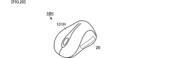
- FIG. 20 is an external perspective view of a holding state detection device according to the eleventh embodiment of the present invention.
- the holding state detection device 10H is a wireless mouse for a computer.
- the holding state detection device 10H includes a housing 131H.
- the casing 131H has a shape obtained by cutting an elliptical sphere into halves.
- the piezoelectric sensor 20 is attached to the housing 131H.
- the piezoelectric sensor 20 may be disposed near the inner surface of the housing 131H or may be attached to the surface. At this time, the piezoelectric sensor 20 is arranged in a region not used in normal click processing, and is arranged at a position where the user is pressed when gripping.
- the gripping state (holding state) is detected by the piezoelectric sensor 20 and the detection unit 30 (not shown). With the detection of the gripping state as a trigger, the mouse can be turned on. On the contrary, when the release of the grip is detected, the detection of the release state of the grip can be used as a trigger to turn off the power of the mouse. At this time, as described above, by making it possible to detect a pressing force or a long press, various other controls (function control or the like) can be performed.
- a wireless mouse for a computer is taken as an example here, the present invention can also be applied to a battery-powered device such as a desktop game wireless controller or a portable game machine.
- FIG. 21 is an external perspective view of a holding state detection device according to the twelfth embodiment of the present invention.
- the holding state detection device 10J is a tablet terminal.
- the holding state detection device 10J includes a housing 141J.
- the casing 141J has a flat plate shape.
- a piezoelectric sensor 20 is attached to the casing 141J.
- the piezoelectric sensor 20 may be disposed in the vicinity of the surface inside the housing 141J or may be attached to the surface. At this time, the piezoelectric sensor 20 is disposed at a position where the user holds the tablet terminal.
- the gripping state (holding state) is detected by the piezoelectric sensor 20 and the detection unit 30 (not shown). With the detection of the gripping state as a trigger, the image display on the display can be turned on. On the contrary, when the release of the grip is detected, the image display on the display can be turned off by using the detection of the release state of the grip as a trigger. Thereby, unnecessary consumption of the battery of the tablet terminal can be suppressed. Also, as described above, by making it possible to detect a pressing force or a long press, various other controls (specific operation input control or the like) can be performed.
- FIG. 22 is an external perspective view of a holding state detection device according to a thirteenth embodiment of the present invention.
- the holding state detection device 10K is a cart.
- the holding state detection device 10K includes a pedestal portion 151K, a gripping portion (arm) 152K, and wheels 153K.
- the gripping part 152K has a cylindrical shape and is physically connected to the pedestal part 151K.
- the piezoelectric sensor 20 is attached to the grip portion 152K.
- the piezoelectric sensor 20 may be disposed near the inner surface of the gripper 152K or may be attached to the surface.
- the grip state (holding state) is detected by the piezoelectric sensor 20 and the detection unit 30 (not shown). With this detection of the gripping state as a trigger, the brake applied to the wheel 153K can be released. Conversely, when the release of the grip is detected, the brake can be applied with the detection of the release state of the grip as a trigger. Thereby, it is possible to prevent the carriage from moving without a user and to release the brake without using a switch or the like for releasing the brake.
- piezoelectric film of polylactic acid is used as the piezoelectric sensor.
- other piezoelectric films such as PVDF can be used depending on the situation.
- polylactic acid a highly reliable holding state detection device without pyroelectricity as described above can be realized.
- a polylactic acid piezoelectric sensor and a pyroelectric piezoelectric sensor such as PVDF may be combined. Thereby, it is possible to detect the holding by the person more accurately.
- piezoelectric ceramics for the piezoelectric sensor.
- a highly flexible polylactic acid piezoelectric film for the piezoelectric sensor it can be easily placed in a housing, is not easily damaged, and can improve reliability.
- a mode in which a piezoelectric sensor that detects a pressure applied to the housing is used has been described.
- a piezoelectric sensor that detects a myoelectric signal can also be used.
- the holding state can be detected by detecting a myoelectric signal generated at the time of gripping without applying pressure, and thus the holding state for a more natural motion can be detected.
Abstract
A holding state detection device (10) is provided with: a housing (101) formed in a shape that can be held by an operator; a piezoelectric sensor (20) mounted in the housing (101); and a detection unit (30) that detects a state in which the housing is held, said state being detected using the change quantity of an output voltage of the piezoelectric sensor (20). The housing (101) has a hollow shape. The piezoelectric sensor (20) has a flat film shape. The piezoelectric sensor (20) is disposed in contact with the inner wall surface of the housing (101). The piezoelectric sensor (20) is configured from a piezoelectric film and a detecting conductor. The piezoelectric film generates a charge by expanding and contracting corresponding to displacement of the housing (101). The charge is outputted as a voltage to the detection unit (30) by means of the detecting conductor. When the detection unit (30) detects that the change of the output voltage of the piezoelectric sensor (20) is large, the detection unit identifies that the housing (101) is being held.
Description
本発明は、人が検出対象の物体を保持していることを検出する保持状態検出装置に関する。
The present invention relates to a holding state detection device that detects that a person is holding an object to be detected.
現在、各種の電子筆記具(デジタルペン)が実用化されている。例えば、特許文献1に記載の電子筆記具は、筐体内に配置されたタクトスイッチと、筐体の外部に突出する操作ボタンを備える。操作者が操作ボタンを押し込むと、操作ボタンの底面がタクトスイッチを押し込む。タクトスイッチは、この押し込みによってオン状態となる。これによって、操作者が電子筆記具を操作したことを検出する。
Currently, various electronic writing instruments (digital pens) are in practical use. For example, an electronic writing instrument described in Patent Literature 1 includes a tact switch disposed in a housing and an operation button that projects outside the housing. When the operator pushes the operation button, the bottom of the operation button pushes the tact switch. The tact switch is turned on by this depression. Thereby, it is detected that the operator has operated the electronic writing instrument.
しかしながら、特許文献1に記載の電子筆記具では、機械的スイッチ(メカニカルスイッチ)を利用しているため、破損、経時劣化による接触不良の故障が生じてしまう。また、操作ボタンを確実に押し込んでタクトスイッチに接触させなければ、保持状態を検出できない。
However, since the electronic writing instrument described in Patent Document 1 uses a mechanical switch (mechanical switch), failure due to contact failure due to breakage or deterioration over time occurs. In addition, the holding state cannot be detected unless the operation button is securely pushed and brought into contact with the tact switch.
したがって、本発明の目的は、操作者に意識させることなく保持状態を検出できる信頼性の高い保持状態検出装置を提供することにある。
Therefore, an object of the present invention is to provide a highly reliable holding state detection device that can detect a holding state without making the operator aware of it.
この発明の保持状態検出装置は、操作者が保持可能な形状からなる筐体と、筐体に装着された圧電センサと、圧電センサの出力電圧の変動量を用いて筐体の保持状態を検出する検出部と、を備えることを特徴としている。
The holding state detection device according to the present invention detects a holding state of a housing using a housing that can be held by an operator, a piezoelectric sensor mounted on the housing, and a variation amount of an output voltage of the piezoelectric sensor. And a detecting unit.
この構成では、操作者が筐体を保持した時に筐体に加わる力の変動が、圧電センサの出力電圧の変動として直接的且つ瞬時的に現れる。したがって、この出力電圧の変動を検出することによって、筐体の保持状態を直接的且つ瞬時的に検出することができる。また、圧電フィルムによる検出のため、機構的な動作部を必要としない。
In this configuration, fluctuations in the force applied to the casing when the operator holds the casing directly and instantaneously appear as fluctuations in the output voltage of the piezoelectric sensor. Therefore, the holding state of the housing can be detected directly and instantaneously by detecting the fluctuation of the output voltage. Further, since the detection is performed by the piezoelectric film, no mechanical operation unit is required.
また、この発明の保持状態検出装置では、圧電センサは、平膜の圧電フィルムと、圧電フィルムの発生する電荷を取り出す導体膜と、を備えることが好ましい。
In the holding state detection device of the present invention, it is preferable that the piezoelectric sensor includes a flat film piezoelectric film and a conductor film that extracts charges generated by the piezoelectric film.
この構成では、圧電センサを薄型にでき、筐体に容易に装着することができる。
In this configuration, the piezoelectric sensor can be made thin and can be easily attached to the housing.
また、この発明の保持状態検出装置では、圧電フィルムは、ポリ乳酸を主成分として含んでおり、一軸方向に延伸されていることが好ましい。
Further, in the holding state detection device of the present invention, the piezoelectric film preferably contains polylactic acid as a main component and is stretched in a uniaxial direction.
この構成では、焦電性の影響を受けず、保持状態を正確に検出することができる。
In this configuration, the holding state can be accurately detected without being affected by pyroelectricity.
また、この発明の保持状態検出装置では、筐体は筒状または箱状であり、圧電センサは、筐体の内壁面に装着されていることが好ましい。
Further, in the holding state detection device of the present invention, it is preferable that the casing is cylindrical or box-shaped, and the piezoelectric sensor is mounted on the inner wall surface of the casing.
この構成では、圧電センサを操作者が直接に触れることが無く、且つ、保持状態を正確に検出することができる。
In this configuration, the operator does not directly touch the piezoelectric sensor, and the holding state can be accurately detected.
また、この発明の保持状態検出装置では、検出部は、変動量が予め設定した閾値よりも大きいことを検出すると、筐体が保持されていると識別することが好ましい。
Further, in the holding state detection device of the present invention, it is preferable that the detection unit identifies that the casing is held when detecting that the fluctuation amount is larger than a preset threshold value.
この構成では、筐体が保持されていることを正確に検出することができる。
In this configuration, it is possible to accurately detect that the housing is held.
また、この発明の保持状態検出装置では、検出部は、変動量が閾値よりも大きくなった後に、変動量が閾値以下になったことを検出すると、筐体の保持が解除されたと識別することが好ましい。
Further, in the holding state detection device of the present invention, the detection unit identifies that the holding of the housing has been released when it is detected that the fluctuation amount is equal to or less than the threshold value after the fluctuation amount is greater than the threshold value. Is preferred.
この構成では、筐体の保持が解除されたことを正確に検出することができる。
In this configuration, it is possible to accurately detect that the housing has been released.
また、この発明の保持状態検出装置では、検出部は、出力電圧が予め設定した動作制御用閾値よりも大きいことを検出すると、保持状態検出装置で実行する動作の開始制御を行ってもよい。
In the holding state detection device of the present invention, the detection unit may perform start control of the operation executed by the holding state detection device when detecting that the output voltage is larger than a preset operation control threshold.
この構成では、保持状態の検出とともに、保持状態検出装置に対する保持状態検出とは別の操作入力を受け付けることができる。
In this configuration, together with the detection of the holding state, an operation input different from the holding state detection for the holding state detection device can be accepted.
また、この発明の保持状態検出装置では、検出部は、出力電圧が予め設定した第1動作制御用閾値よりも大きいことを検出し、その後の出力電圧が予め設定した第2動作制御用閾値よりも小さいことを検出すると、保持状態検出装置で実行する動作の開始制御を行うようにしてもよい。
In the holding state detection device of the present invention, the detection unit detects that the output voltage is larger than the preset first operation control threshold, and the subsequent output voltage is set higher than the preset second operation control threshold. If it is detected that the value is smaller, control for starting the operation executed by the holding state detection device may be performed.
この構成では、保持状態の検出とともに、保持状態検出装置に対する保持状態検出とは別の操作入力を受け付けることができる。
In this configuration, together with the detection of the holding state, an operation input different from the holding state detection for the holding state detection device can be accepted.
また、この発明の保持状態検出装置は、次の構成であってもよい。検出部は、出力電圧が極大になった時間を検出し、その後の出力電圧が極小になった時間を検出し、これらの時間間隔を算出する。検出部は、時間間隔が動作制御用の時間閾値よりも長いことを検出すると、保持状態検出装置で実行する動作の開始制御を行う。
Further, the holding state detection device of the present invention may have the following configuration. The detection unit detects a time when the output voltage becomes maximum, detects a time when the output voltage thereafter becomes minimum, and calculates these time intervals. When the detection unit detects that the time interval is longer than the time threshold for operation control, the detection unit performs start control of the operation executed by the holding state detection device.
この構成では、保持状態の検出とともに、保持状態検出装置に対する保持状態検出とは別の操作入力を受け付けることができる。
In this configuration, together with the detection of the holding state, an operation input different from the holding state detection for the holding state detection device can be accepted.
この発明によれば、操作者に意識させることなく保持状態を検出できる信頼性の高い保持状態検出装置を実現できる。
According to the present invention, it is possible to realize a highly reliable holding state detection device that can detect a holding state without making the operator aware of it.
本発明の第1の実施形態に係る保持状態検出装置について、図を参照して説明する。図1(A)は、本発明の第1の実施形態に係る保持状態検出装置の斜視図である。図1(B)は、本発明の第1の実施形態に係る保持状態検出装置の断面図である。図1(B)は、保持状態検出装置における圧電センサが装着された領域の断面図である。図2は、本発明の第1の実施形態に係る保持状態検出装置の機能ブロック図である。本実施形態では、電子筆記具の形状からなる保持状態検出装置を例に説明する。
A holding state detection apparatus according to the first embodiment of the present invention will be described with reference to the drawings. FIG. 1A is a perspective view of a holding state detection apparatus according to the first embodiment of the present invention. FIG. 1B is a cross-sectional view of the holding state detection device according to the first embodiment of the present invention. FIG. 1B is a cross-sectional view of a region where the piezoelectric sensor is mounted in the holding state detection device. FIG. 2 is a functional block diagram of the holding state detection apparatus according to the first embodiment of the present invention. In the present embodiment, a holding state detection device having the shape of an electronic writing instrument will be described as an example.
図1に示すように、保持状態検出装置10は、圧電センサ20および筐体101を備える。また、図2に示すように、保持状態検出装置10は、圧電センサ20と検出部30とを備える。圧電センサ20と検出部30は接続されている。検出部30は、圧電センサ20の出力電圧を検出し、筐体101が操作者によって保持されているか否かを検出する。なお、検出部30は、図1に図示していないが、筐体101の内部に装着されていてもよく、筐体101の外部に配置していてもよい。筐体101の外部に配置する態様では、圧電センサ20と検出部30を有線または無線で接続すればよい。
As shown in FIG. 1, the holding state detection device 10 includes a piezoelectric sensor 20 and a housing 101. As shown in FIG. 2, the holding state detection device 10 includes a piezoelectric sensor 20 and a detection unit 30. The piezoelectric sensor 20 and the detection unit 30 are connected. The detection unit 30 detects the output voltage of the piezoelectric sensor 20 and detects whether or not the casing 101 is held by the operator. Although not shown in FIG. 1, the detection unit 30 may be mounted inside the housing 101 or may be disposed outside the housing 101. In an embodiment in which the piezoelectric sensor 20 and the detection unit 30 are arranged outside the housing 101, the piezoelectric sensor 20 and the detection unit 30 may be connected by wire or wirelessly.
筐体101は、円筒状であり、中空を有する。筐体101は、絶縁性材料からなる。筐体101の長尺方向(円周方向に直交する方向)の一方端には先細り形状の端部102を備える。
The housing 101 is cylindrical and has a hollow shape. The casing 101 is made of an insulating material. A tapered end 102 is provided at one end of the casing 101 in the longitudinal direction (direction orthogonal to the circumferential direction).
この保持状態検出装置10を電子筆記具として利用する場合、操作者は、保持状態検出装置10に対して次のような取り扱いをする。操作者は、筐体101の円筒部分を保持して、先細り形状の端部102を他の電子機器(例えば電子黒板等)に接触させる。操作者が保持状態検出装置10を移動させると、先細り形状の端部102の先端部も移動する。他の電子機器は、この動きをセンシングすることによって、操作者の操作入力を受け付ける。
When using the holding state detection device 10 as an electronic writing instrument, the operator handles the holding state detection device 10 as follows. The operator holds the cylindrical portion of the housing 101 and brings the tapered end portion 102 into contact with another electronic device (for example, an electronic blackboard). When the operator moves the holding state detection device 10, the tip end portion of the tapered end portion 102 also moves. Other electronic devices accept the operation input of the operator by sensing this movement.
圧電センサ20は可撓性を有する平膜であり、図1(B)に示すように、筐体101の内面壁に配置されている。この際、圧電センサ20は、内壁面において、円周方向に沿うように配置されている。
The piezoelectric sensor 20 is a flexible flat film, and is disposed on the inner wall of the housing 101 as shown in FIG. At this time, the piezoelectric sensor 20 is arranged along the circumferential direction on the inner wall surface.
圧電センサ20は、平膜の圧電フィルムと検出用導体とを備える。検出用導体は、圧電フィルムの対向する二面の平膜面に形成されている。検出用導体は、検出部30に接続されている。
The piezoelectric sensor 20 includes a flat film piezoelectric film and a detection conductor. The detection conductor is formed on two opposing flat membrane surfaces of the piezoelectric film. The detection conductor is connected to the detection unit 30.
圧電フィルムは、伸縮によって対向する平膜面に電荷を発生する圧電材料である。例えば、圧電フィルムは、一軸延伸されたポリ乳酸(PLA)、より具体的にはL型ポリ乳酸(PLLA)である。ポリ乳酸の一軸延伸方向は、圧電フィルムの長手方向に対して略45°を成す方向である。なお、この成す角は45°であることが最も好ましいが、±10°程度の範囲内であればよい。なお、ここで、圧電フィルムの長手方向は、図1の例では、筐体101の内面壁に沿った円周方向である。
Piezoelectric film is a piezoelectric material that generates electric charges on opposing flat membrane surfaces by expansion and contraction. For example, the piezoelectric film is uniaxially stretched polylactic acid (PLA), more specifically L-type polylactic acid (PLLA). The uniaxial stretching direction of polylactic acid is a direction that forms approximately 45 ° with respect to the longitudinal direction of the piezoelectric film. The angle formed is most preferably 45 °, but may be within a range of about ± 10 °. Here, the longitudinal direction of the piezoelectric film is a circumferential direction along the inner wall of the housing 101 in the example of FIG.
ここで、圧電性シート21を形成するPLLAの特性について説明する。
Here, the characteristics of PLLA forming the piezoelectric sheet 21 will be described.
PLLAはキラル高分子からなる。PLLAは、主鎖が螺旋構造を有する。PLLAは、一軸延伸された方向に分子が配向し、当該分子の配向によって圧電性を有する。そして、一軸延伸されたPLLAは、圧電フィルムが伸長することによって、電荷を発生する。発生する電荷量は、圧電フィルムの伸長量によって決まる。一軸延伸されたPLLAの圧電定数は、高分子中で非常に高い部類に属する。例えば、PLLAの圧電歪み定数d14は、延伸条件、熱処理条件、添加物の配合等の条件を整えることにより10~20pC/Nという高い値が得られる。
PLLA consists of a chiral polymer. PLLA has a helical structure in the main chain. In PLLA, molecules are oriented in a uniaxially stretched direction, and have piezoelectricity due to the orientation of the molecules. The uniaxially-stretched PLLA generates electric charges when the piezoelectric film expands. The amount of charge generated is determined by the amount of expansion of the piezoelectric film. The piezoelectric constant of uniaxially stretched PLLA belongs to a very high class among polymers. For example, the piezoelectric strain constant d 14 of PLLA can be as high as 10 to 20 pC / N by adjusting conditions such as stretching conditions, heat treatment conditions, and additive blending.
そして、圧電フィルムが伸長する方向と、一軸延伸方向が45°の角度をなす態様において、効果的に電荷を発生することができる。
And, in an embodiment in which the direction in which the piezoelectric film extends and the uniaxial stretching direction form an angle of 45 °, electric charges can be generated effectively.
なお、圧電フィルムの延伸倍率は3~8倍程度が好適である。延伸後に熱処理を施すことにより、ポリ乳酸の延びきり鎖結晶の結晶化が促進され圧電定数が向上する。尚、二軸延伸した場合はそれぞれの軸の延伸倍率を異ならせることによって一軸延伸と同様の効果を得ることが出来る。例えばある方向をX軸としてその方向に8倍、その軸に直交するY軸方向に2倍の延伸を施した場合、圧電定数に関してはおよそX軸方向に4倍の一軸延伸を施した場合とほぼ同等の効果が得られる。単純に一軸延伸した圧電フィルムは延伸軸方向に沿って裂け易いため、前述したような二軸延伸を行うことにより幾分強度を増すことができる。
The stretching ratio of the piezoelectric film is preferably about 3 to 8 times. By performing a heat treatment after stretching, crystallization of the extended chain crystal of polylactic acid is promoted and the piezoelectric constant is improved. In the case of biaxial stretching, the same effect as that of uniaxial stretching can be obtained by varying the stretching ratio of each axis. For example, when a certain direction is taken as an X-axis, 8 times in that direction, and 2 times in the Y-axis direction perpendicular to that axis, the piezoelectric constant is about 4 times in the X-axis direction, Almost the same effect can be obtained. Since a uniaxially stretched piezoelectric film is easily torn along the stretch axis direction, the strength can be somewhat increased by performing biaxial stretching as described above.
また、PLLAは、延伸等による分子の配向処理で圧電性を生じるので、PVDF等の他のポリマーや圧電セラミックスのように、ポーリング処理を行う必要がない。すなわち、強誘電体に属さないPLLAの圧電性は、PVDFやPZT等の強誘電体のようにイオンの分極によって発現するものではなく、分子の特徴的な構造である螺旋構造に由来するものである。このため、PLLAには、他の強誘電性の圧電体で生じる焦電性が生じない。さらに、PVDF等は経時的に圧電定数の変動が見られ、場合によっては圧電定数が著しく低下する場合があるが、PLLAの圧電定数は経時的に極めて安定している。したがって、出力電荷量が使用時間の長さや周囲環境に影響されない。
In addition, PLLA generates piezoelectricity by molecular orientation treatment such as stretching, and therefore does not need to be subjected to poling treatment like other polymers such as PVDF and piezoelectric ceramics. That is, the piezoelectricity of PLLA that does not belong to ferroelectrics is not expressed by the polarization of ions like ferroelectrics such as PVDF and PZT, but is derived from a helical structure that is a characteristic structure of molecules. is there. For this reason, the pyroelectricity generated in other ferroelectric piezoelectric materials does not occur in PLLA. Further, PVDF or the like shows a change in piezoelectric constant over time, and in some cases, the piezoelectric constant may be significantly reduced, but the piezoelectric constant of PLLA is extremely stable over time. Therefore, the output charge amount is not affected by the length of use time or the surrounding environment.
このように圧電フィルムに、一軸延伸したPLLAを用いることによって、操作者が筐体101を持った際に生じる温度変化の影響を受けず、信頼性の高い圧電センサ20を実現できる。また、操作者が筐体101を保持したことによる筐体101の少しの変位であっても電荷を発生するので、操作者による筐体101の保持、すなわち筐体101の保持状態を高感度に検出することができる。
Thus, by using uniaxially stretched PLLA for the piezoelectric film, it is possible to realize the highly reliable piezoelectric sensor 20 without being affected by the temperature change that occurs when the operator holds the casing 101. Further, since the operator generates a charge even if the casing 101 is slightly displaced by holding the casing 101, the operator can hold the casing 101, that is, the holding state of the casing 101 with high sensitivity. Can be detected.
図3は、本発明の第1の実施形態に係る保持状態検出装置の圧電センサの出力電圧を示すグラフである。図3に示すように、筐体101を保持していない期間では、電圧の変動は殆ど無く、変動量は極小さい。一方、筐体101を保持している期間では、電圧の変動が激しく、変動量は大きい。
FIG. 3 is a graph showing the output voltage of the piezoelectric sensor of the holding state detection device according to the first embodiment of the present invention. As shown in FIG. 3, during the period when the housing 101 is not held, there is almost no voltage fluctuation and the fluctuation amount is extremely small. On the other hand, during the period in which the housing 101 is held, the voltage fluctuates greatly and the fluctuation amount is large.
したがって、検出部30は、次に示すフローを実行することによって、筐体101が保持されたことを検出することができる。図4は、本発明の第1の実施形態に係る保持状態検出装置における保持の検出フローを示すフローチャートである。
Therefore, the detection unit 30 can detect that the casing 101 is held by executing the following flow. FIG. 4 is a flowchart showing a holding detection flow in the holding state detection apparatus according to the first embodiment of the present invention.
検出部30は、圧電センサ20の出力電圧を観測する(S101)。検出部30は、予め設定した計測単位時間当たりの出力電圧の変動量を算出する(S102)。変動量は、例えば、計測単位時間内での最大電圧と最小電圧との差である。
The detection unit 30 observes the output voltage of the piezoelectric sensor 20 (S101). The detection unit 30 calculates a fluctuation amount of the output voltage per preset measurement unit time (S102). The fluctuation amount is, for example, a difference between the maximum voltage and the minimum voltage within the measurement unit time.
検出部30は、変動量と閾値電圧(保持検出用閾値)Vwとを比較する。検出部30は、変動量が閾値電圧Vwよりも大きいことを検出すると(S103:YES)、筐体101が保持されていること(持ち上げられていること)を識別する(S104)。検出部30は、変動量が閾値電圧Vw以下であれば(S103:NO)、筐体101が保持されていないと識別する。そして、検出部30は、継続して出力電圧を計測し、単位時間毎に変動量を算出して、閾値と比較する。
The detection unit 30 compares the fluctuation amount with a threshold voltage (holding detection threshold) Vw. When detecting that the fluctuation amount is larger than the threshold voltage Vw (S103: YES), the detection unit 30 identifies that the housing 101 is being held (lifted) (S104). If the fluctuation amount is equal to or lower than the threshold voltage Vw (S103: NO), the detection unit 30 identifies that the housing 101 is not held. Then, the detection unit 30 continuously measures the output voltage, calculates the fluctuation amount for each unit time, and compares it with the threshold value.
これにより、保持状態検出装置10は、筐体101が保持されていることを検出することができる。
Thereby, the holding state detection device 10 can detect that the casing 101 is held.
また、検出部30は、次に示すフローを実行することによって、筐体101の保持状態を検出することができる。図5は、本発明の第1の実施形態に係る保持状態検出装置における保持状態の検出フローを示すフローチャートである。なお、図5における保持の検出のステップS104までは同じであり、説明は省略する。
Further, the detection unit 30 can detect the holding state of the casing 101 by executing the following flow. FIG. 5 is a flowchart showing a holding state detection flow in the holding state detection apparatus according to the first embodiment of the present invention. Note that the steps up to step S104 of holding detection in FIG.
検出部30は、変動量と閾値Vwとの比較を継続し、変動量が閾値Vw以下にならない期間(S105:NO)では、筐体101が保持されていると識別し続ける。
The detection unit 30 continues the comparison between the variation amount and the threshold value Vw, and continues to identify that the casing 101 is held in a period (S105: NO) in which the variation amount does not become the threshold value Vw or less.
検出部30は、変動量が閾値Vw以下であることを検出すると(S105:YES)、計時を開始する。検出部30は、変動量が閾値Vw以下であることを検出したタイミングを基準として変動量が閾値Vw以下である状態が継続する時間を経過時間として計測する。検出部30は、経過時間が閾値時間よりも短い期間(S106:NO)では、筐体101が保持されていると識別し続ける。
When the detecting unit 30 detects that the fluctuation amount is equal to or less than the threshold value Vw (S105: YES), it starts measuring time. The detection unit 30 measures, as an elapsed time, a time during which the state in which the variation amount is equal to or less than the threshold value Vw continues with reference to the timing at which the variation amount is detected as the threshold value Vw or less. The detection unit 30 continues to identify that the casing 101 is held in a period (S106: NO) in which the elapsed time is shorter than the threshold time.
検出部30は、経過時間が閾値時間に達すると、筐体101の保持(持ち上げ)が解除されたと識別する(S107)。
When the elapsed time reaches the threshold time, the detection unit 30 identifies that the holding (lifting) of the casing 101 is released (S107).
これにより、検出部30は、筐体101の保持状態(保持されているか否か)を検出することができる。
Thereby, the detection unit 30 can detect the holding state of the casing 101 (whether or not it is held).
なお、検出部30は、保持していない期間(初期状態)における平均電圧を基準電圧として、計測単位時間内における最大電圧もしくは最小電圧と基準電圧との差を、変動量に設定してもよい。この場合、基準電圧からの電位差で規定される図3閾値Vaを用いればよい。
Note that the detection unit 30 may set the difference between the maximum voltage or the minimum voltage within the measurement unit time and the reference voltage as the variation amount, with the average voltage in the non-holding period (initial state) as the reference voltage. . In this case, the threshold value Va in FIG. 3 defined by the potential difference from the reference voltage may be used.
このような構成とすることで、操作者によって筐体101が保持されたことを正確且つ確実に検出することができる。また、圧電センサ20の変位に対する感度が高いため、筐体101が保持されたことを瞬時的に検出することができる。また、機械的なスイッチを用いないため、破損や経年劣化による接触不良が発生せず、信頼性が高い。
With such a configuration, it is possible to accurately and reliably detect that the casing 101 is held by the operator. In addition, since the sensitivity to the displacement of the piezoelectric sensor 20 is high, it can be instantaneously detected that the housing 101 is held. Further, since no mechanical switch is used, there is no contact failure due to breakage or aging deterioration, and the reliability is high.
また、このような構成および処理を用いることによって、保持されているか保持されていないかを正確且つ確実に検出することができる。また、保持状態の変化を、タイムラグを生じることなく検出することができる。
Further, by using such a configuration and processing, it is possible to accurately and reliably detect whether it is held or not held. Further, it is possible to detect a change in the holding state without causing a time lag.
また、このような構成を用いることで、操作者がスイッチ等の操作を行わなくても、単に筐体101を保持しただけで、筐体101を保持していることを検出することができる。すなわち、操作者に意識させることなく保持状態を検出することができる。
Further, by using such a configuration, it is possible to detect that the case 101 is held by simply holding the case 101 without the operator performing an operation such as a switch. That is, the holding state can be detected without making the operator aware of it.
なお、本実施形態では、筐体101における先細り形状の端部102との接続部付近に圧電センサ20を装着する態様を示した。しかしながら、筐体101の他の位置に圧電センサ20を装着してもよい。ただし、本実施形態に示すように、操作者が最も把持しやすい位置に圧電センサ20を装着することによって、より正確且つ確実に保持状態を検出することができる。
In the present embodiment, the mode in which the piezoelectric sensor 20 is mounted in the vicinity of the connection portion between the housing 101 and the tapered end portion 102 is shown. However, the piezoelectric sensor 20 may be mounted at another position of the housing 101. However, as shown in the present embodiment, the holding state can be detected more accurately and reliably by mounting the piezoelectric sensor 20 at a position that is most easily gripped by the operator.
次に、本発明の第2の実施形態に係る保持状態検出装置について、図を参照して説明する。図6は、本発明の第2の実施形態に係る保持状態検出装置の斜視図である。
Next, a holding state detection apparatus according to a second embodiment of the present invention will be described with reference to the drawings. FIG. 6 is a perspective view of a holding state detection apparatus according to the second embodiment of the present invention.
本実施形態に係る保持状態検出装置10Aは、第1の実施形態に係る保持状態検出装置10に対して、圧電センサ20Aの形状および筐体101に対する装着態様が異なるものである。他の構成は、第1の実施形態に係る保持状態検出装置10と同じである。
The holding state detection device 10A according to the present embodiment is different from the holding state detection device 10 according to the first embodiment in the shape of the piezoelectric sensor 20A and the mounting mode with respect to the housing 101. Other configurations are the same as those of the holding state detection apparatus 10 according to the first embodiment.
圧電センサ20Aは、筐体101の円周方向の全周に亘るだけでなく、筐体101の長手方向にも広がる形状である。このような構成とすることで、筐体101の把持位置に影響されることなく、保持状態を正確且つ確実に検出することができる。
The piezoelectric sensor 20A has a shape that extends not only over the entire circumference of the casing 101 but also in the longitudinal direction of the casing 101. With such a configuration, the holding state can be accurately and reliably detected without being affected by the gripping position of the housing 101.
次に、本発明の第3の実施形態に係る保持状態検出装置について、図を参照して説明する。図7は、本発明の第3の実施形態に係る保持状態検出装置の斜視図である。
Next, a holding state detection apparatus according to a third embodiment of the present invention will be described with reference to the drawings. FIG. 7 is a perspective view of a holding state detection apparatus according to the third embodiment of the present invention.
本実施形態に係る保持状態検出装置10Bは、第1の実施形態に係る保持状態検出装置10に対して、圧電センサ20Bの形状および筐体101に対する装着態様が異なるものである。他の構成は、第1の実施形態に係る保持状態検出装置10と同じである。
The holding state detection device 10B according to the present embodiment is different from the holding state detection device 10 according to the first embodiment in the shape of the piezoelectric sensor 20B and the mounting mode with respect to the housing 101. Other configurations are the same as those of the holding state detection apparatus 10 according to the first embodiment.
圧電センサ20Bは、筐体101の長手方向と圧電センサ20Bの長手方向とが平行になるように、筐体101に装着されている。このような構成であっても、第1、第2の実施形態と同様に、保持状態を正確且つ確実に検出することができる。さらに、本実施形態の構成を用いることによって、把持位置に影響されることなく保持状態を検出し、且つ、圧電フィルムの面積を小さくすることができる。これにより、安価で且つ圧電センサ20Bを筐体101に貼り付けやすい。
The piezoelectric sensor 20B is mounted on the casing 101 so that the longitudinal direction of the casing 101 and the longitudinal direction of the piezoelectric sensor 20B are parallel to each other. Even with such a configuration, as in the first and second embodiments, the holding state can be accurately and reliably detected. Furthermore, by using the configuration of the present embodiment, the holding state can be detected without being affected by the gripping position, and the area of the piezoelectric film can be reduced. Thereby, it is cheap and it is easy to affix the piezoelectric sensor 20B to the housing 101.
次に、本発明の第4の実施形態に係る保持状態検出装置について、図を参照して説明する。図8は、本発明の第4の実施形態に係る保持状態検出装置の斜視図である。
Next, a holding state detection apparatus according to a fourth embodiment of the present invention will be described with reference to the drawings. FIG. 8 is a perspective view of a holding state detection apparatus according to the fourth embodiment of the present invention.
本実施形態に係る保持状態検出装置10Cは、第1の実施形態に係る保持状態検出装置10に対して、圧電センサ20Cの形状および筐体101に対する装着態様が異なるものである。他の構成は、第1の実施形態に係る保持状態検出装置10と同じである。
The holding state detection device 10C according to the present embodiment is different from the holding state detection device 10 according to the first embodiment in the shape of the piezoelectric sensor 20C and the mounting mode with respect to the housing 101. Other configurations are the same as those of the holding state detection apparatus 10 according to the first embodiment.
圧電センサ20Cは長尺状である。圧電センサ20Cは、筐体101の円周面に沿って螺旋状に装着されている。この場合、圧電フィルムの一軸延伸方向は、圧電センサ20Cの長尺方向または長尺方向に直交する短尺に平行であるとよい。
The piezoelectric sensor 20C is long. The piezoelectric sensor 20 </ b> C is spirally attached along the circumferential surface of the housing 101. In this case, the uniaxial stretching direction of the piezoelectric film is preferably parallel to a long direction of the piezoelectric sensor 20C or a short length orthogonal to the long direction.
このような構成であっても、第2の実施形態と同様に、把持位置に影響されることなく、保持状態を正確且つ確実に検出することができる。さらに、本実施形態の構成では、圧電フィルムの面積を小さくすることができる。
Even with such a configuration, the holding state can be accurately and reliably detected without being affected by the gripping position, as in the second embodiment. Furthermore, in the configuration of the present embodiment, the area of the piezoelectric film can be reduced.
次に、本発明の第5の実施形態に係る保持状態検出装置について、図を参照して説明する。図9は、本発明の第5の実施形態に係る保持状態検出装置に用いる圧電フィルム装着治具に圧電フィルムを装着した状態を示す側面図である。
Next, a holding state detection apparatus according to a fifth embodiment of the present invention will be described with reference to the drawings. FIG. 9 is a side view showing a state in which the piezoelectric film is mounted on the piezoelectric film mounting jig used in the holding state detection apparatus according to the fifth embodiment of the present invention.
本実施形態に係る保持状態検出装置の基本構造は、第1の実施形態に係る保持状態検出装置と同じであり、圧電センサ20の取り付け構造が異なる。
The basic structure of the holding state detection device according to the present embodiment is the same as that of the holding state detection device according to the first embodiment, and the mounting structure of the piezoelectric sensor 20 is different.
圧電センサ20は、高い弾性を有する装着治具40の表面に貼り付けられている。装着治具40は、筐体101の内壁面の形状に応じて湾曲した形状である。圧電センサ20は、装着治具40の外周面に貼り付けられている。
The piezoelectric sensor 20 is affixed to the surface of the mounting jig 40 having high elasticity. The mounting jig 40 has a curved shape according to the shape of the inner wall surface of the housing 101. The piezoelectric sensor 20 is affixed to the outer peripheral surface of the mounting jig 40.
圧電センサ20を筐体101の内部に装着する際には、装着治具40を定常状態よりも湾曲させた状態で、筐体101内に挿嵌する。挿嵌された装着治具40は定常状態に戻ろうとして、筐体101の内壁面に向かう方向へ圧電センサ20押しつける。これにより、圧電センサ20を筐体101の内壁面に当接させた状態で保持することができる。
When mounting the piezoelectric sensor 20 inside the housing 101, the mounting jig 40 is inserted into the housing 101 in a state of being bent from a steady state. The inserted mounting jig 40 presses the piezoelectric sensor 20 in a direction toward the inner wall surface of the housing 101 in an attempt to return to the steady state. As a result, the piezoelectric sensor 20 can be held in a state of being in contact with the inner wall surface of the housing 101.
このような構成を用いることで、圧電センサ20を筐体101の内壁面に接着剤等を用いて直接貼り付けるよりも、圧電センサ20を筐体101の内壁面に容易に装着することができる。
By using such a configuration, it is possible to easily attach the piezoelectric sensor 20 to the inner wall surface of the housing 101, rather than directly attaching the piezoelectric sensor 20 to the inner wall surface of the housing 101 using an adhesive or the like. .
次に、本発明の第6の実施形態に係る保持状態検出装置について、図を参照して説明する。図10は、本発明の第6の実施形態に係る保持状態検出装置における圧電センサと検出部の構成を示す分解斜視図である。図11は、本発明の第6の実施形態に係る保持状態検出装置における圧電センサと検出部の構成を示す分解状態での側面断面図である。
Next, a holding state detection apparatus according to a sixth embodiment of the present invention will be described with reference to the drawings. FIG. 10 is an exploded perspective view showing the configuration of the piezoelectric sensor and the detection unit in the holding state detection device according to the sixth embodiment of the present invention. FIG. 11 is a side cross-sectional view in an exploded state showing a configuration of a piezoelectric sensor and a detection unit in a holding state detection apparatus according to a sixth embodiment of the present invention.
本実施形態に係る保持状態検出装置10Dは、圧電センサ20Dおよび検出部30Dを備える。圧電センサ20Dの機能は、第1の実施形態に係る圧電センサ20の機能と同じである。検出部30Dの機能は、第1の実施形態に係る検出部30と同じである。
The holding state detection device 10D according to the present embodiment includes a piezoelectric sensor 20D and a detection unit 30D. The function of the piezoelectric sensor 20D is the same as the function of the piezoelectric sensor 20 according to the first embodiment. The function of the detection unit 30D is the same as that of the detection unit 30 according to the first embodiment.
圧電センサ20Dは、ベースフィルム201、検出用導体202、圧電性シート203、第1グランド導体204、第2グランド導体205、および保護膜206,207を備える。
The piezoelectric sensor 20D includes a base film 201, a detection conductor 202, a piezoelectric sheet 203, a first ground conductor 204, a second ground conductor 205, and protective films 206 and 207.
ベースフィルム201は、絶縁性を有し、例えばPETからなる。ベースフィルム201は、平面視して略矩形で長尺状である。ベースフィルム201の表面には、検出用導体202が形成されている。検出用導体202は、ベースフィルム201の長手方向における一方端側の所定範囲に形成されている。ベースフィルム201の表面には、端子導体2081,2082、グランド用導体209、配線導体2101,2102が形成されている。端子導体2081,2082は、ベースフィルム201の長手方向における他方端付近に形成されている。グランド用導体209は、ベースフィルム201の長手方向において端子導体2082と検出用導体202との間に配置されている。配線導体2101は、端子導体2081と検出用導体202とを接続している。配線導体2102は、端子導体2082とグランド用導体209とを接続している。ベースフィルム201における検出用導体202の形成領域と、端子導体2081,2082およびグランド用導体209の形成領域と間には、切り欠き211が形成されている。
The base film 201 has insulating properties and is made of, for example, PET. The base film 201 is substantially rectangular and long in plan view. A detection conductor 202 is formed on the surface of the base film 201. The detection conductor 202 is formed in a predetermined range on one end side in the longitudinal direction of the base film 201. On the surface of the base film 201, terminal conductors 2081 and 2082, a ground conductor 209, and wiring conductors 2101 and 2102 are formed. The terminal conductors 2081 and 2082 are formed near the other end in the longitudinal direction of the base film 201. The ground conductor 209 is disposed between the terminal conductor 2082 and the detection conductor 202 in the longitudinal direction of the base film 201. The wiring conductor 2101 connects the terminal conductor 2081 and the detection conductor 202. The wiring conductor 2102 connects the terminal conductor 2082 and the ground conductor 209. A notch 211 is formed between the formation region of the detection conductor 202 in the base film 201 and the formation region of the terminal conductors 2081 and 2082 and the ground conductor 209.
圧電性シート203は、検出用導体202の表面に配置されている。圧電性シート203の平面形状は、検出用導体202の平面形状と略同じである。
The piezoelectric sheet 203 is disposed on the surface of the detection conductor 202. The planar shape of the piezoelectric sheet 203 is substantially the same as the planar shape of the detection conductor 202.
第1グランド導体204は、ベースフィルム201の表面側に配置されている。これにより、圧電性シート203は、検出用導体202と第1グランド導体204の長手方向の一方端側の領域とに挟みこまれる。第1グランド導体204の長手方向の他方端側の領域は、グランド用導体209に当接している。なお、第1グランド導体204と配線導体2101が重なり合う部分には、絶縁性フィルムが配置されている。図11に示すように、第1グランド導体204は、導体膜2041と、導体膜2041の両面に配置された導電性粘着材2042とからなる。
The first ground conductor 204 is disposed on the surface side of the base film 201. Accordingly, the piezoelectric sheet 203 is sandwiched between the detection conductor 202 and the region on the one end side in the longitudinal direction of the first ground conductor 204. A region on the other end side in the longitudinal direction of the first ground conductor 204 is in contact with the ground conductor 209. Note that an insulating film is disposed in a portion where the first ground conductor 204 and the wiring conductor 2101 overlap. As shown in FIG. 11, the first ground conductor 204 includes a conductor film 2041 and a conductive adhesive material 2042 disposed on both surfaces of the conductor film 2041.
保護膜206は、第1グランド導体204の表面側に配置されている。保護膜206は、絶縁性フィルムであり、例えばPETからなる。保護膜206は、ベースフィルム201と略同じ形状である。
The protective film 206 is disposed on the surface side of the first ground conductor 204. The protective film 206 is an insulating film and is made of, for example, PET. The protective film 206 has substantially the same shape as the base film 201.
第2グランド導体205は、ベースフィルム202の表面に配置されている。図11に示すように、第2グランド導体205は、導体膜2051と、導体膜2051の両面に配置された導電性粘着材2052とからなる。第2グランド導体205は、切り欠き211の領域において、第1グランド導体204と導通されている。
The second ground conductor 205 is disposed on the surface of the base film 202. As shown in FIG. 11, the second ground conductor 205 includes a conductor film 2051 and a conductive adhesive material 2052 disposed on both surfaces of the conductor film 2051. The second ground conductor 205 is electrically connected to the first ground conductor 204 in the region of the notch 211.
保護膜207は、第2グランド導体205の裏面側に配置されている。保護膜207は、絶縁性フィルムであり、例えばPETからなる。保護膜207は、ベースフィルム201よりも長さが短い。保護膜207は、第2グランド導体205の長手方向における他方端側の領域に重なっており、他方端側の領域には重なっていない。
The protective film 207 is disposed on the back side of the second ground conductor 205. The protective film 207 is an insulating film and is made of, for example, PET. The protective film 207 is shorter than the base film 201. The protective film 207 overlaps the region on the other end side in the longitudinal direction of the second ground conductor 205 and does not overlap the region on the other end side.
検出部30Dは、ベース基板301と電子部品302とを備える。ベース基板301には回路パターンが形成されている。電子部品302は、ベース基板301に実装されている。ベース基板301の回路パターンにおける外部接続用端子は、異方性導電膜310を介して、端子導体2081,2082に接続されている。
The detection unit 30D includes a base substrate 301 and an electronic component 302. A circuit pattern is formed on the base substrate 301. The electronic component 302 is mounted on the base substrate 301. External connection terminals in the circuit pattern of the base substrate 301 are connected to terminal conductors 2081 and 2082 through an anisotropic conductive film 310.
このような構成からなる圧電センサ20Dと検出部30Dとの複合モジュールは、図12に示すように、筐体101に実装される。図12は、本発明の第6の実施形態に係る保持状態検出装置の部品配置状態を示す断面図である。
The composite module of the piezoelectric sensor 20D and the detection unit 30D having such a configuration is mounted on the housing 101 as shown in FIG. FIG. 12 is a cross-sectional view showing a component arrangement state of the holding state detection device according to the sixth embodiment of the present invention.
筐体101は、円筒形であり、筐体101内には、電子部品ASSYbiが実装されている。圧電センサ20Dは、筐体101の内壁面に沿って配置されている。圧電センサ20Dの長手方向における検出部30Dが接続する端部を除く略全面は、筐体101の内壁面に当接している。この際、図10、図11に示すように、第2グランド導体205の一部が保護膜207に覆われることなく露出しているので、この露出部における導電性粘着材2052によって、圧電センサ20Dは、筐体101の内壁面に粘着している。これにより、圧電センサ20Dは、筐体101に固定されている。
The housing 101 has a cylindrical shape, and an electronic component ASSYbi is mounted in the housing 101. The piezoelectric sensor 20 </ b> D is disposed along the inner wall surface of the housing 101. The substantially entire surface of the piezoelectric sensor 20D in the longitudinal direction except the end to which the detection unit 30D is connected is in contact with the inner wall surface of the housing 101. At this time, as shown in FIGS. 10 and 11, since a part of the second ground conductor 205 is exposed without being covered with the protective film 207, the piezoelectric sensor 20D is formed by the conductive adhesive material 2052 in the exposed portion. Is adhered to the inner wall surface of the housing 101. Thereby, the piezoelectric sensor 20D is fixed to the housing 101.
圧電センサ20Dの長手方向における検出部30D側の端部は、筐体101の内側に湾曲している。これにより、検出部30Dは、筐体101の内部空間の略中央に配置されている。検出部30Dは、電子部品ASSYbiに固定されている。
The end on the detection unit 30D side in the longitudinal direction of the piezoelectric sensor 20D is curved inward of the housing 101. As a result, the detection unit 30 </ b> D is disposed in the approximate center of the internal space of the housing 101. The detection unit 30D is fixed to the electronic component ASSYbi.
このような構成とすることによって、圧電センサ20Dと検出部30Dを一体化でき、筐体101内に配置することができる。
By adopting such a configuration, the piezoelectric sensor 20D and the detection unit 30D can be integrated and arranged in the housing 101.
次に、本発明の第7の実施形態に係る保持状態検出装置について、図を参照して説明する。図13は、本発明の第7の実施形態に係る保持状態検出装置の検出概念を説明するための電圧波形図である。
Next, a holding state detection apparatus according to a seventh embodiment of the present invention will be described with reference to the drawings. FIG. 13 is a voltage waveform diagram for explaining the detection concept of the holding state detection device according to the seventh embodiment of the present invention.
本実施形態に係る保持状態検出装置の構造は、上述の各実施形態に示したいずれかの構造を用いている。本実施形態に係る保持状態検出装置は、圧電センサの出力電圧によって実行する動作が異なる。
The structure of the holding state detection device according to the present embodiment uses any one of the structures shown in the above-described embodiments. The holding state detection device according to the present embodiment differs in operation to be executed depending on the output voltage of the piezoelectric sensor.
図13は、筐体を保持した後に筐体を長押しした状態の出力電圧波形を示している。なお、長押しとは、筐体に対して外部から所定時間に亘って連続的に押圧力をかける状態をいう。
FIG. 13 shows an output voltage waveform in a state where the casing is held down after being held. Note that the long press refers to a state in which a pressing force is continuously applied to the housing from outside for a predetermined time.
上述のように、筐体が保持されている期間では、保持していない期間よりも電圧の変動量が大きくなる。そして、筐体に押圧力を加えると、単に保持している状態よりも、電圧が大きく変動する。また、筐体を長押しした場合、押し始めで電圧値が基準電圧よりも高くなり、押し終わりで電圧値が基準電圧よりも低くなる。
As described above, the voltage fluctuation amount is larger in the period in which the casing is held than in the period in which the casing is not held. When a pressing force is applied to the housing, the voltage fluctuates more than when it is simply held. Further, when the casing is long pressed, the voltage value becomes higher than the reference voltage at the start of pressing, and the voltage value becomes lower than the reference voltage at the end of pressing.
検出部は、動作検出用の高電圧側閾値THHと、低電圧側閾値THLを予め記憶している。高電圧側閾値THHは、単なる保持状態での電圧値よりも高く設定されている。高電圧側閾値THHは、意図的に押圧が加えられたときに出力電圧が高電圧側閾値THHを上回るように設定されている。低電圧側閾値THLは、単なる保持状態での電圧値よりも低く設定されている。高電圧側閾値THHは、本発明の動作制御用閾値および第1動作制御用閾値である。低電圧側閾値THLは、意図的に長押しが行われて押圧が解放されたときに出力電圧が低電圧側閾値THLを下回るように設定されている。低電圧側閾値THLは、本発明の第2動作制御用閾値である。
The detection unit stores in advance a high voltage side threshold THH and a low voltage side threshold THL for operation detection. The high voltage side threshold THH is set to be higher than the voltage value in a simple holding state. The high voltage side threshold value THH is set so that the output voltage exceeds the high voltage side threshold value THH when a pressure is intentionally applied. The low voltage side threshold value THL is set lower than the voltage value in the simple holding state. The high voltage side threshold value THH is an operation control threshold value and a first operation control threshold value according to the present invention. The low voltage side threshold value THL is set so that the output voltage falls below the low voltage side threshold value THL when the long press is intentionally performed and the press is released. The low voltage side threshold THL is the second operation control threshold of the present invention.
図14は、本実施形態に係る保持状態検出装置の検出部における第1の操作入力検出フローを示すフローチャートである。
FIG. 14 is a flowchart showing a first operation input detection flow in the detection unit of the holding state detection apparatus according to the present embodiment.
検出部は、上述の実施形態の方法を用いて、保持状態を検出する(S201)。検出部は、出力電圧を経時的に計測する(S202)。検出部は、出力電圧と高電圧側閾値THHを逐次比較し、出力電圧が高電圧側閾値THHよりも大きくなったことを検出すると(S203:YES)、動作開始制御(S204)を行う。動作開始制御とは、予め設定した動作を開始する制御であり、例えば、電子筆記具の場合、描ける線の太さを変更する、描ける線の色を変更する等の動作を開始する制御である。また、複数の動作モードが予め設定されている場合には、動作開始制御によってモードの切り替えを行うこともできる。
The detecting unit detects the holding state using the method of the above-described embodiment (S201). The detection unit measures the output voltage over time (S202). The detection unit sequentially compares the output voltage and the high voltage side threshold value THH, and when it is detected that the output voltage is larger than the high voltage side threshold value THH (S203: YES), the operation start control (S204) is performed. The operation start control is control for starting a preset operation. For example, in the case of an electronic writing instrument, control for starting an operation such as changing the thickness of a drawable line or changing the color of a drawable line. Further, when a plurality of operation modes are set in advance, the modes can be switched by operation start control.
なお、検出部は、出力電圧が高電圧側閾値THH以下であれば(S203:NO)、出力電圧の計測、および、出力電圧と高電圧側閾値THHとの比較を継続する。
If the output voltage is equal to or lower than the high voltage side threshold THH (S203: NO), the detection unit continues to measure the output voltage and compare the output voltage with the high voltage side threshold THH.
このような処理を行うことによって、単なる保持検出だけでなく、意図的な押圧による保持状態における別の動作の操作入力を検出して、この動作制御を実行することができる。この際、別の動作を実行させるためのスイッチや操作子を別途必要としない。
By performing such a process, it is possible to execute this operation control by detecting an operation input of another operation in the holding state by intentional pressing as well as merely holding detection. At this time, a switch and an operator for performing another operation are not required separately.
図15は、本実施形態に係る保持状態検出装置の検出部における第2の操作入力検出フローを示すフローチャートである。
FIG. 15 is a flowchart showing a second operation input detection flow in the detection unit of the holding state detection device according to the present embodiment.
検出部は、上述の実施形態の方法を用いて、保持状態を検出する(S211)。検出部は、出力電圧を経時的に計測する(S212)。検出部は、出力電圧と高電圧側閾値THHを逐次比較し、出力電圧が高電圧側閾値THHよりも大きくなったことを検出すると(S213:YES)、これを記憶する。次に、検出部は、出力電圧と低電圧側閾値THLを逐次比較し、出力電圧が低電圧側閾値THLよりも小さくなったことを検出すると(S214:YES)、動作開始制御(S215)を行う。
The detecting unit detects the holding state using the method of the above-described embodiment (S211). The detection unit measures the output voltage over time (S212). The detection unit sequentially compares the output voltage and the high voltage side threshold value THH, and if it detects that the output voltage is greater than the high voltage side threshold value THH (S213: YES), it stores this. Next, the detection unit sequentially compares the output voltage with the low voltage side threshold value THL, and when detecting that the output voltage is smaller than the low voltage side threshold value THL (S214: YES), the operation start control (S215) is performed. Do.
なお、検出部は、出力電圧が高電圧側閾値THH以下の場合(S213:NO)、および、出力電圧が低電圧側閾値THL以上の場合(S214:NO)、出力電圧の計測、および、出力電圧と高電圧側閾値THHおよび低電圧側閾値THLとの比較を継続する。
When the output voltage is equal to or lower than the high voltage side threshold THH (S213: NO), and when the output voltage is equal to or higher than the low voltage side threshold THL (S214: NO), the detection unit measures and outputs the output voltage. The comparison of the voltage with the high voltage side threshold THH and the low voltage side threshold THL is continued.
このような処理を行うことによって、単なる保持検出だけでなく、意図的な長押しによる保持状態における別の動作の操作入力を検出して、この動作制御を実行することができる。この際、別の動作を実行させるためのスイッチや操作子を別途必要としない。
By performing such processing, it is possible to execute this operation control by detecting an operation input of another operation in a holding state by intentional long press as well as merely holding detection. At this time, a switch and an operator for performing another operation are not required separately.
なお、上述の方法では、出力電圧値によって長押しを検出する態様を示した。しかしながら、時間によって長押しを検出することも可能である。図16は、本実施形態に係る保持状態検出装置の検出部における第3の操作入力検出フローを示すフローチャートである。
In the above-described method, a mode in which a long press is detected based on the output voltage value is shown. However, it is possible to detect a long press according to time. FIG. 16 is a flowchart showing a third operation input detection flow in the detection unit of the holding state detection apparatus according to the present embodiment.
検出部は、上述の実施形態の方法を用いて、保持状態を検出する(S221)。検出部は、出力電圧を経時的に計測する(S222)。検出部は、出力電圧のピーク検出を行って、極大値の時間t(MX)を検出する(S223)。検出部は、極大値の検出後、引き続き出力電圧のピーク検出を行って、極小値の時間t(MN)を検出する(S224)。
The detection unit detects the holding state using the method of the above-described embodiment (S221). The detection unit measures the output voltage over time (S222). The detection unit detects the peak of the output voltage and detects the maximum time t (MX) (S223). After detecting the maximum value, the detection unit subsequently detects the peak of the output voltage and detects the minimum value time t (MN) (S224).
長押しが行われた場合、上述のように、押し始めで電圧が基準電圧よりも高く極大になり、押し終わりで電圧が基準電圧よりも低く極小になる。したがって、これら極大の時間と極小の時間の差は、押圧されている時間に比例する。
When a long press is performed, the voltage becomes higher than the reference voltage and becomes maximum at the start of pressing as described above, and the voltage becomes lower than the reference voltage and becomes minimum at the end of pressing. Therefore, the difference between the maximum time and the minimum time is proportional to the pressed time.
検出部は、極大値の時間t(MX)と極小値の時間t(MN)との時間間隔Tを算出する(S225)。検出部は、長押し検出用の閾値時間THtを予め記憶している。長押し検出用の閾値時間THtは、本発明の動作制御用の時間閾値に相当する。検出部は、時間間隔Tと閾値時間THtを比較し、時間間隔Tが閾値時間THtよりも長いことを検出すると(S226:YES)、動作開始制御(S227)を行う。
The detection unit calculates a time interval T between the maximum time t (MX) and the minimum time t (MN) (S225). The detection unit stores in advance a threshold time THt for long press detection. The threshold time THt for long press detection corresponds to the time threshold for operation control of the present invention. When the detection unit compares the time interval T with the threshold time THt and detects that the time interval T is longer than the threshold time THt (S226: YES), it performs operation start control (S227).
なお、検出部は、時間間隔Tが閾値時間THtよりも長くなければ(S226:NO)、出力電圧の計測、時間間隔T、時間間隔Tと閾値時間THtとの比較を継続する。
If the time interval T is not longer than the threshold time THt (S226: NO), the detection unit continues to measure the output voltage and compare the time interval T and the time interval T with the threshold time THt.
なお、図16では、極大値および極小値を用いる態様を示したが、上述の出力電圧が押圧検出用の閾値を超えた時間を、時間間隔の算出に用いてもよい。
In addition, although the aspect which uses the maximum value and the minimum value was shown in FIG. 16, you may use for the calculation of a time interval the time when the above-mentioned output voltage exceeded the threshold value for a press detection.
このような処理であっても、単なる保持検出だけでなく、意図的な長押しによる保持状態における別の動作の操作入力を検出することができる。
Even in such a process, it is possible to detect not only mere holding detection but also an operation input of another operation in the holding state by intentional long press.
なお、上述の単発の押圧の検出と長押しの検出とを組み合わせて実行することができる。これにより、複数の動作に対する制御を、専用のスイッチを用いることなく開始することができる。
It should be noted that the above-described single-press detection and long-press detection can be combined and executed. Thereby, control with respect to several operation | movement can be started, without using a dedicated switch.
次に、本発明の第8の実施形態に係る保持状態検出装置について、図を参照して説明する。図17は、本発明の第8の実施形態に係る保持状態検出装置の機能ブロック図である。
Next, a holding state detection device according to an eighth embodiment of the present invention will be described with reference to the drawings. FIG. 17 is a functional block diagram of a holding state detection apparatus according to the eighth embodiment of the present invention.
本実施形態に係る保持状態検出装置10Eは、上述の実施形態に係る保持状態検出装置に対してローパスフィルタ50を追加した点で異なる。他の構成は、実施形態に係る保持状態検出装置と同じである。
The holding state detection device 10E according to this embodiment is different in that a low-pass filter 50 is added to the holding state detection device according to the above-described embodiment. Other configurations are the same as those of the holding state detection device according to the embodiment.
ローパスフィルタ50は、圧電センサ20と検出部30との間に接続されている。ローパスフィルタ50は、約100[kHz]を遮断周波数とする低域通過フィルタである。
The low pass filter 50 is connected between the piezoelectric sensor 20 and the detection unit 30. The low-pass filter 50 is a low-pass filter having a cutoff frequency of about 100 [kHz].
人の押圧によって発生する圧電センサの変位の周波数は、数[Hz]から数十[Hz]である。一方、外部からの振動、衝撃による周波数は、数百[Hz]から数千[Hz]である。したがって、このローパスフィルタ50を用いることによって、検出部30には、押圧による変位を起因とする周波数の出力信号のみが入力される。
The frequency of the displacement of the piezoelectric sensor generated by human pressing is several [Hz] to several tens [Hz]. On the other hand, the frequency due to external vibration and impact is several hundreds [Hz] to several thousand [Hz]. Therefore, by using the low-pass filter 50, only an output signal having a frequency caused by displacement due to pressing is input to the detection unit 30.
これにより、保持状態および押圧を、より正確に検出することができる。
This makes it possible to detect the holding state and the pressure more accurately.
上述の実施形態では、円筒形の筐体である態様、すなわち、保持状態検出装置が電子筆記具のようなものである態様を示したが、マウス、タブレット端末、携帯型電話器等の他の形状の筐体に適用することができる。この際、本発明に係る保持状態検出装置が装着される機器は、操作者が装置の一部を把持して利用するものであることが好ましい。以下に、各種の態様の一部を図示して説明する。
In the above-described embodiment, an aspect that is a cylindrical housing, that is, an aspect in which the holding state detection device is like an electronic writing instrument has been shown. It can be applied to other cases. At this time, it is preferable that the device on which the holding state detection device according to the present invention is mounted is used by an operator holding a part of the device. Hereinafter, some of the various aspects will be illustrated and described.
本発明の第9の実施形態に係る保持状態検出装置について、図を参照して説明する。図18は、本発明の第9の実施形態に係る保持状態検出装置の外観斜視図である。
A holding state detection apparatus according to a ninth embodiment of the present invention will be described with reference to the drawings. FIG. 18 is an external perspective view of a holding state detection device according to the ninth embodiment of the present invention.
保持状態検出装置10Fは、シャワー装置である。保持状態検出装置10Fは、シャワーヘッド111Fと、把持部112Fとを備える。把持部112Fは筒状であり、シャワーヘッド111Fに物理的に接続されている。把持部112Fには、圧電センサ20が装着されている。圧電センサ20は、把持部112Fの内部の表面付近に配置されていても、表面に貼り付けられていてもよい。ただし、表面に貼り付ける場合には、防水フィルム等によって覆われている。
The holding state detection device 10F is a shower device. The holding state detection device 10F includes a shower head 111F and a grip portion 112F. The grip portion 112F is cylindrical and is physically connected to the shower head 111F. The piezoelectric sensor 20 is attached to the grip portion 112F. The piezoelectric sensor 20 may be disposed in the vicinity of the surface inside the grip portion 112F, or may be attached to the surface. However, when pasting on the surface, it is covered with a waterproof film or the like.
使用者が把持部112Fを把持すると、圧電センサ20および検出部30(図示せず)によって、把持状態(保持状態)が検出される。この把持状態の検出をトリガとして、シャワーヘッド111Fに水、湯を供給することができる。この際、上述のように、押圧力や長押しを検出できるようにすることで、押圧力や長押し時間を用いて、水量(湯量)の調整、水温の調整、供給の停止等を制御することもできる。
When the user grips the grip portion 112F, the grip state (holding state) is detected by the piezoelectric sensor 20 and the detection unit 30 (not shown). Water or hot water can be supplied to the shower head 111F using the detection of the gripping state as a trigger. At this time, as described above, it is possible to detect the pressing force and the long pressing, thereby controlling the adjustment of the water amount (the amount of hot water), the adjustment of the water temperature, the stoppage of the supply, etc. using the pressing force and the long pressing time. You can also.
なお、PLLAは、上述のように圧電特性の温度依存性が低いので、このような態様では、より有効である。
It should be noted that PLLA is more effective in this mode because the temperature dependence of piezoelectric characteristics is low as described above.
本発明の第10の実施形態に係る保持状態検出装置について、図を参照して説明する。図19は、本発明の第10の実施形態に係る保持状態検出装置の外観斜視図である。
A holding state detection apparatus according to a tenth embodiment of the present invention will be described with reference to the drawings. FIG. 19 is an external perspective view of a holding state detection device according to the tenth embodiment of the present invention.
保持状態検出装置10Gは、懐中電灯である。保持状態検出装置10Gは、ライト部121Gと、把持部122Gとを備える。把持部122Gは筒状であり、ライト部121Gに物理的に接続されている。把持部122Gには、圧電センサ20が装着されている。圧電センサ20は、把持部122Gの内部の表面付近に配置されていても、表面に貼り付けられていてもよい。
The holding state detection device 10G is a flashlight. The holding state detection device 10G includes a light unit 121G and a grip unit 122G. The holding part 122G is cylindrical and is physically connected to the light part 121G. The piezoelectric sensor 20 is attached to the grip portion 122G. The piezoelectric sensor 20 may be disposed in the vicinity of the surface inside the grip portion 122G or may be attached to the surface.
使用者が把持部122Gを把持すると、圧電センサ20および検出部30(図示せず)によって、把持状態(保持状態)が検出される。この把持状態の検出をトリガとして、ライト部121Gを点灯させることができる。この際、上述のように、押圧力や長押しを検出できるようにすることで、押圧力や長押し時間を用いて、調光や、ライトの消灯を制御することもできる。
When the user grips the grip portion 122G, the grip state (holding state) is detected by the piezoelectric sensor 20 and the detection unit 30 (not shown). The light unit 121G can be turned on with the detection of the gripping state as a trigger. At this time, as described above, by making it possible to detect the pressing force and the long pressing, it is possible to control the dimming and the light extinction using the pressing force and the long pressing time.
本発明の第11の実施形態に係る保持状態検出装置について、図を参照して説明する。図20は、本発明の第11の実施形態に係る保持状態検出装置の外観斜視図である。
A holding state detection apparatus according to an eleventh embodiment of the present invention will be described with reference to the drawings. FIG. 20 is an external perspective view of a holding state detection device according to the eleventh embodiment of the present invention.
保持状態検出装置10Hは、コンピュータ用の無線式マウスである。保持状態検出装置10Hは、筐体131Hを備える。筐体131Hは楕円球体を半分に切断した形状である。筐体131Hには、圧電センサ20が装着されている。圧電センサ20は、筐体131Hの内部の表面付近に配置されていても、表面に貼り付けられていてもよい。この際、圧電センサ20は、通常のクリック処理では用いない領域に配置されており、使用者が把持時に押圧が加わる位置に配置されている。
The holding state detection device 10H is a wireless mouse for a computer. The holding state detection device 10H includes a housing 131H. The casing 131H has a shape obtained by cutting an elliptical sphere into halves. The piezoelectric sensor 20 is attached to the housing 131H. The piezoelectric sensor 20 may be disposed near the inner surface of the housing 131H or may be attached to the surface. At this time, the piezoelectric sensor 20 is arranged in a region not used in normal click processing, and is arranged at a position where the user is pressed when gripping.
使用者が筐体131Hを把持すると、圧電センサ20および検出部30(図示せず)によって、把持状態(保持状態)が検出される。この把持状態の検出をトリガとして、マウスの電源をオン状態にすることができる。逆に、把持の解放が検出されると、この把持の解放状態の検出をトリガとして、マウスの電源をオフ状態にすることができる。この際、上述のように、押圧力や長押しを検出できるようにすることで、他の各種の制御(ファンクション制御等)を行うこともできる。
When the user grips the housing 131H, the gripping state (holding state) is detected by the piezoelectric sensor 20 and the detection unit 30 (not shown). With the detection of the gripping state as a trigger, the mouse can be turned on. On the contrary, when the release of the grip is detected, the detection of the release state of the grip can be used as a trigger to turn off the power of the mouse. At this time, as described above, by making it possible to detect a pressing force or a long press, various other controls (function control or the like) can be performed.
なお、ここでは、コンピュータ用の無線式マウスを例にしたが、卓上ゲームの無線式コントローラ、携帯型のゲーム機等、電池で駆動する機器にも適用することができる。
Note that although a wireless mouse for a computer is taken as an example here, the present invention can also be applied to a battery-powered device such as a desktop game wireless controller or a portable game machine.
本発明の第12の実施形態に係る保持状態検出装置について、図を参照して説明する。図21は、本発明の第12の実施形態に係る保持状態検出装置の外観斜視図である。
A holding state detection apparatus according to a twelfth embodiment of the present invention will be described with reference to the drawings. FIG. 21 is an external perspective view of a holding state detection device according to the twelfth embodiment of the present invention.
保持状態検出装置10Jは、タブレット式端末である。保持状態検出装置10Jは、筐体141Jを備える。筐体141Jは平板形状である。筐体141Jには、圧電センサ20が装着されている。圧電センサ20は、筐体141Jの内部の表面付近に配置されていても、表面に貼り付けられていてもよい。この際、圧電センサ20は、使用者がタブレット式端末を把持する位置に配置されている。
The holding state detection device 10J is a tablet terminal. The holding state detection device 10J includes a housing 141J. The casing 141J has a flat plate shape. A piezoelectric sensor 20 is attached to the casing 141J. The piezoelectric sensor 20 may be disposed in the vicinity of the surface inside the housing 141J or may be attached to the surface. At this time, the piezoelectric sensor 20 is disposed at a position where the user holds the tablet terminal.
使用者が筐体141Jを把持すると、圧電センサ20および検出部30(図示せず)によって、把持状態(保持状態)が検出される。この把持状態の検出をトリガとして、ディスプレイの画像表示をオン状態にすることができる。逆に、把持の解放が検出されると、この把持の解放状態の検出をトリガとして、ディスプレイの画像表示をオフ状態にすることができる。これにより、タブレット式端末の電池の不要な消耗を抑制することができる。また、上述のように、押圧力や長押しを検出できるようにすることで、他の各種の制御(特定の操作入力制御等)を行うこともできる。
When the user grips the casing 141J, the gripping state (holding state) is detected by the piezoelectric sensor 20 and the detection unit 30 (not shown). With the detection of the gripping state as a trigger, the image display on the display can be turned on. On the contrary, when the release of the grip is detected, the image display on the display can be turned off by using the detection of the release state of the grip as a trigger. Thereby, unnecessary consumption of the battery of the tablet terminal can be suppressed. Also, as described above, by making it possible to detect a pressing force or a long press, various other controls (specific operation input control or the like) can be performed.
本発明の第13の実施形態に係る保持状態検出装置について、図を参照して説明する。図22は、本発明の第13の実施形態に係る保持状態検出装置の外観斜視図である。
A holding state detection device according to a thirteenth embodiment of the present invention will be described with reference to the drawings. FIG. 22 is an external perspective view of a holding state detection device according to a thirteenth embodiment of the present invention.
保持状態検出装置10Kは、台車である。保持状態検出装置10Kは、台座部151Kと、把持部(アーム)152Kと、車輪153Kとを備える。把持部152Kは筒状であり、台座部151Kに物理的に接続されている。把持部152Kには、圧電センサ20が装着されている。圧電センサ20は、把持部152Kの内部の表面付近に配置されていても、表面に貼り付けられていてもよい。
The holding state detection device 10K is a cart. The holding state detection device 10K includes a pedestal portion 151K, a gripping portion (arm) 152K, and wheels 153K. The gripping part 152K has a cylindrical shape and is physically connected to the pedestal part 151K. The piezoelectric sensor 20 is attached to the grip portion 152K. The piezoelectric sensor 20 may be disposed near the inner surface of the gripper 152K or may be attached to the surface.
使用者が把持部152Kを把持すると、圧電センサ20および検出部30(図示せず)によって、把持状態(保持状態)が検出される。この把持状態の検出をトリガとして、車輪153Kにかけられたブレーキを解除することができる。逆に、把持の解放が検出されると、この把持の解放状態の検出をトリガとして、ブレーキをかけることができる。これにより、使用者がいない間に、台車が勝手に移動することを防止でき、且つ、ブレーキ解除だけのためのスイッチ等を用いることなく、ブレーキを解除することができる。
When the user grips the grip portion 152K, the grip state (holding state) is detected by the piezoelectric sensor 20 and the detection unit 30 (not shown). With this detection of the gripping state as a trigger, the brake applied to the wheel 153K can be released. Conversely, when the release of the grip is detected, the brake can be applied with the detection of the release state of the grip as a trigger. Thereby, it is possible to prevent the carriage from moving without a user and to release the brake without using a switch or the like for releasing the brake.
また、上述のように、押圧力や長押しを検出できるようにすることで、押圧力や長押し時間を用いて、ブレーキの効き等を制御することもできる。これにより、使用状況に応じたブレーキの効きを調整することができる。例えば、坂道を下る場合にブレーキの効きを適宜強くする等の調整を行うことができる。
Also, as described above, by making it possible to detect the pressing force and the long pressing, it is possible to control the effectiveness of the brake using the pressing force and the long pressing time. Thereby, the effectiveness of the brake according to a use condition can be adjusted. For example, it is possible to make adjustments such as increasing the braking effectiveness as appropriate when going down a slope.
なお、上述の実施形態では、圧電センサに、ポリ乳酸の圧電フィルムを用いる例を示したが、状況に応じてPVDF等の他の圧電フィルムを用いることも可能である。但し、ポリ乳酸を用いることで、上述のように焦電性が無く信頼性の高い保持状態検出装置を実現できる。また、ポリ乳酸の圧電センサとPVDF等の焦電性を有する圧電センサとを組み合わせてもよい。これにより、人による保持をさらに正確に検出することができる。また、圧電センサには、圧電セラミックスを用いることも可能である。しかしながら、圧電センサに可撓性の高いポリ乳酸の圧電フィルムを用いることによって、筐体への配置が容易であり、破損が生じ難く信頼性を向上させることができる。
In the above-described embodiment, an example in which a piezoelectric film of polylactic acid is used as the piezoelectric sensor has been described. However, other piezoelectric films such as PVDF can be used depending on the situation. However, by using polylactic acid, a highly reliable holding state detection device without pyroelectricity as described above can be realized. Also, a polylactic acid piezoelectric sensor and a pyroelectric piezoelectric sensor such as PVDF may be combined. Thereby, it is possible to detect the holding by the person more accurately. Moreover, it is also possible to use piezoelectric ceramics for the piezoelectric sensor. However, by using a highly flexible polylactic acid piezoelectric film for the piezoelectric sensor, it can be easily placed in a housing, is not easily damaged, and can improve reliability.
また、上述の実施形態では、筐体に係る押圧を検出する圧電センサを用いる態様を示したが、筋電信号を検出する圧電センサを用いることも可能である。この場合、押圧を加えなくても、把持時に生じる筋電信号を検出して、保持状態を検出できるので、より自然な動作に対する保持状態を検出することもできる。
In the above-described embodiment, a mode in which a piezoelectric sensor that detects a pressure applied to the housing is used has been described. However, a piezoelectric sensor that detects a myoelectric signal can also be used. In this case, the holding state can be detected by detecting a myoelectric signal generated at the time of gripping without applying pressure, and thus the holding state for a more natural motion can be detected.
10,10A,10B,10C,10D,10E,10F,10G,10H,10J,10K:保持状態検出装置
20,20A,20B,20C,20D:圧電センサ
30,30D:検出部
40:装着部材
50:ローパスフィルタ
101:筐体
102:先細り形状の端部
111F:シャワーヘッド
112F:把持部
121G:ライト部
122G:把持部
131H,141J:筐体
151K:台座部
152K:把持部(アーム)
153K:車輪
201:ベースフィルム
202:検出用導体
203:圧電性シート
204:第1グランド導体
205:第2グランド導体
206,207:保護膜
301:ベース基板
302:電子部品
2041,2051:導体膜
2042,2052:導電性粘着材 10, 10A, 10B, 10C, 10D, 10E, 10F, 10G, 10H, 10J, 10K: holding state detection devices 20, 20A, 20B, 20C, 20D: piezoelectric sensors 30, 30D: detection unit 40: mounting member 50: Low-pass filter 101: Housing 102: Tapered end portion 111F: Shower head 112F: Grip portion 121G: Light portion 122G: Grip portion 131H, 141J: Housing 151K: Base portion 152K: Grip portion (arm)
153K: Wheel 201: Base film 202: Detection conductor 203: Piezoelectric sheet 204: First ground conductor 205:Second ground conductor 206, 207: Protective film 301: Base substrate 302: Electronic component 2041, 2051: Conductor film 2042 2052: Conductive adhesive material
20,20A,20B,20C,20D:圧電センサ
30,30D:検出部
40:装着部材
50:ローパスフィルタ
101:筐体
102:先細り形状の端部
111F:シャワーヘッド
112F:把持部
121G:ライト部
122G:把持部
131H,141J:筐体
151K:台座部
152K:把持部(アーム)
153K:車輪
201:ベースフィルム
202:検出用導体
203:圧電性シート
204:第1グランド導体
205:第2グランド導体
206,207:保護膜
301:ベース基板
302:電子部品
2041,2051:導体膜
2042,2052:導電性粘着材 10, 10A, 10B, 10C, 10D, 10E, 10F, 10G, 10H, 10J, 10K: holding
153K: Wheel 201: Base film 202: Detection conductor 203: Piezoelectric sheet 204: First ground conductor 205:
Claims (9)
- 操作者が保持可能な形状からなる筐体と、
前記筐体に装着された圧電センサと、
前記圧電センサの出力電圧の変動量を用いて前記筐体の保持状態を検出する検出部と、を備える保持状態検出装置。 A housing having a shape that can be held by the operator;
A piezoelectric sensor mounted on the housing;
And a detection unit that detects a holding state of the housing using a fluctuation amount of an output voltage of the piezoelectric sensor. - 前記圧電センサは、
平膜の圧電フィルムと、
該圧電フィルムの発生する電荷を取り出す導体膜と、を備える、
請求項1に記載の保持状態検出装置。 The piezoelectric sensor is
A flat film piezoelectric film,
A conductor film for extracting electric charges generated by the piezoelectric film,
The holding state detection device according to claim 1. - 前記圧電フィルムは、ポリ乳酸を主成分として含んでおり、一軸方向に延伸されている、
請求項2に記載の保持状態検出装置。 The piezoelectric film contains polylactic acid as a main component and is stretched in a uniaxial direction.
The holding state detection device according to claim 2. - 前記筐体は筒状または箱状であり、
前記圧電センサは、前記筐体の内壁面に装着されている、
請求項1乃至請求項3のいずれかに記載の保持状態検出装置。 The housing is cylindrical or box-shaped,
The piezoelectric sensor is attached to the inner wall surface of the housing.
The holding state detection apparatus according to any one of claims 1 to 3. - 前記検出部は、
前記変動量が予め設定した保持検出用閾値よりも大きいことを検出すると、前記筐体が保持されていると識別する、
請求項1乃至請求項4のいずれかに記載の保持状態検出装置。 The detector is
When it is detected that the fluctuation amount is greater than a preset holding detection threshold, the case is identified as being held;
The holding state detection apparatus according to any one of claims 1 to 4. - 前記検出部は、
前記変動量が前記保持検出用閾値よりも大きくなった後に、前記変動量が前記保持検出用閾値以下になったことを検出すると、前記筐体の保持が解除されたと識別する、
請求項5に記載の保持状態検出装置。 The detector is
When it is detected that the fluctuation amount has become equal to or smaller than the holding detection threshold after the fluctuation amount becomes larger than the holding detection threshold, it is identified that the holding of the housing is released.
The holding state detection apparatus according to claim 5. - 前記検出部は、前記出力電圧が予め設定した動作制御用閾値よりも大きいことを検出すると、保持状態検出装置で実行する動作の開始制御を行う、
請求項5または請求項6に記載の保持状態検出装置。 When the detection unit detects that the output voltage is larger than a preset operation control threshold value, the detection unit performs start control of an operation executed by the holding state detection device.
The holding state detection device according to claim 5 or 6. - 前記検出部は、
前記出力電圧が予め設定した第1動作制御用閾値よりも大きいことを検出し、その後の前記出力電圧が予め設定した第2動作制御用閾値よりも小さいことを検出すると、保持状態検出装置で実行する動作の開始制御を行う、
請求項5乃至請求項7のいずれかに記載の保持状態検出装置。 The detector is
When it is detected that the output voltage is larger than a preset first operation control threshold, and thereafter the output voltage is detected to be smaller than a preset second operation control threshold, the holding state detection device executes Control to start the operation
The holding state detection device according to any one of claims 5 to 7. - 前記検出部は、
前記出力電圧が極大になった時間を検出し、その後の前記出力電圧が極小になった時間を検出し、これらの時間間隔を算出し、
前記時間間隔が動作制御用の時間閾値よりも長いことを検出すると、保持状態検出装置で実行する動作の開始制御を行う、
請求項5乃至請求項8のいずれかに記載の保持状態検出装置。 The detector is
Detecting the time when the output voltage is maximized, detecting the time when the output voltage is subsequently minimized, calculating these time intervals,
When it is detected that the time interval is longer than the time threshold for operation control, the start control of the operation executed by the holding state detection device is performed.
The holding state detection device according to any one of claims 5 to 8.
Priority Applications (4)
| Application Number | Priority Date | Filing Date | Title |
|---|---|---|---|
| CN201580048822.XA CN106716310A (en) | 2014-09-12 | 2015-06-05 | Holding state detection device |
| JP2016547726A JP6265272B2 (en) | 2014-09-12 | 2015-06-05 | Holding state detection device |
| CN202210985539.1A CN115468685A (en) | 2014-09-12 | 2015-06-05 | Holding state detection device |
| US15/454,155 US10378973B2 (en) | 2014-09-12 | 2017-03-09 | Device for detecting holding state of an object |
Applications Claiming Priority (2)
| Application Number | Priority Date | Filing Date | Title |
|---|---|---|---|
| JP2014-185888 | 2014-09-12 | ||
| JP2014185888 | 2014-09-12 |
Related Child Applications (1)
| Application Number | Title | Priority Date | Filing Date |
|---|---|---|---|
| US15/454,155 Continuation US10378973B2 (en) | 2014-09-12 | 2017-03-09 | Device for detecting holding state of an object |
Publications (1)
| Publication Number | Publication Date |
|---|---|
| WO2016038951A1 true WO2016038951A1 (en) | 2016-03-17 |
Family
ID=55458714
Family Applications (1)
| Application Number | Title | Priority Date | Filing Date |
|---|---|---|---|
| PCT/JP2015/066350 WO2016038951A1 (en) | 2014-09-12 | 2015-06-05 | Holding state detection device |
Country Status (4)
| Country | Link |
|---|---|
| US (1) | US10378973B2 (en) |
| JP (2) | JP6265272B2 (en) |
| CN (2) | CN106716310A (en) |
| WO (1) | WO2016038951A1 (en) |
Cited By (3)
| Publication number | Priority date | Publication date | Assignee | Title |
|---|---|---|---|---|
| CN109791859A (en) * | 2016-09-23 | 2019-05-21 | 株式会社村田制作所 | Piezoelectric device and display device |
| CN110908527A (en) * | 2018-09-18 | 2020-03-24 | 苹果公司 | Stylus for electronic devices |
| WO2020100587A1 (en) * | 2018-11-13 | 2020-05-22 | 株式会社村田製作所 | Rotary operation detecting mechanism and rotary operation detecting method |
Families Citing this family (6)
| Publication number | Priority date | Publication date | Assignee | Title |
|---|---|---|---|---|
| WO2016194690A1 (en) * | 2015-05-29 | 2016-12-08 | 株式会社村田製作所 | Piezoelectric film sensor and holding state detection device |
| US10564724B1 (en) * | 2016-09-20 | 2020-02-18 | Apple Inc. | Touch-based input device with haptic feedback |
| WO2018062057A1 (en) * | 2016-09-27 | 2018-04-05 | 三井化学株式会社 | Piezoelectric substrate attachment structure, sensor module, moving body, and protecting body |
| GB2562758B (en) * | 2017-05-24 | 2021-05-12 | Sony Interactive Entertainment Inc | Input device and method |
| JP7047996B1 (en) * | 2020-06-01 | 2022-04-05 | 株式会社村田製作所 | Sensor |
| WO2024058104A1 (en) * | 2022-09-16 | 2024-03-21 | 株式会社村田製作所 | Pen-type electronic apparatus |
Citations (3)
| Publication number | Priority date | Publication date | Assignee | Title |
|---|---|---|---|---|
| JPH10269007A (en) * | 1997-03-26 | 1998-10-09 | Seiko Epson Corp | Writing tool type coordinate input device |
| WO2013161784A1 (en) * | 2012-04-27 | 2013-10-31 | 株式会社村田製作所 | Operation input device and information display device |
| JP2013242819A (en) * | 2012-05-23 | 2013-12-05 | Hitachi Consumer Electronics Co Ltd | Pen type input device |
Family Cites Families (15)
| Publication number | Priority date | Publication date | Assignee | Title |
|---|---|---|---|---|
| US5134348A (en) * | 1989-04-07 | 1992-07-28 | Canon Kabushiki Kaisha | Vibration wave motor |
| JP3270527B2 (en) * | 1992-07-08 | 2002-04-02 | 呉羽化学工業株式会社 | Cylindrical or curved piezoelectric element |
| JP2000214016A (en) * | 1999-01-27 | 2000-08-04 | Futaba Corp | Man power detecting sensor |
| JP4155111B2 (en) * | 2003-01-31 | 2008-09-24 | ぺんてる株式会社 | Status notification device and shaft body using the status notification device |
| US6985138B2 (en) * | 2003-08-29 | 2006-01-10 | Motorola, Inc. | Input writing device |
| JP4748299B2 (en) * | 2004-12-03 | 2011-08-17 | セイコーエプソン株式会社 | Electronic paper and electronic equipment |
| FR2888528B1 (en) * | 2005-07-12 | 2007-09-21 | Commissariat Energie Atomique | ELECTRONIC PEN WITH THREE DIMENSIONAL EFFORT SENSOR |
| JP2009053109A (en) * | 2007-08-28 | 2009-03-12 | Aisin Seiki Co Ltd | Piezoelectric film sensor |
| JP2009211552A (en) | 2008-03-05 | 2009-09-17 | Fuji Xerox Co Ltd | Electronic writing tool |
| JP2012027541A (en) * | 2010-07-20 | 2012-02-09 | Sony Corp | Contact pressure detection device and input device |
| JP2012063844A (en) * | 2010-09-14 | 2012-03-29 | Fuji Xerox Co Ltd | System, device and program for identifying user |
| JP5810707B2 (en) * | 2011-07-25 | 2015-11-11 | ソニー株式会社 | Information processing device |
| JP2014062962A (en) | 2012-09-20 | 2014-04-10 | Sony Corp | Information processing apparatus, writing instrument, information processing method, and program |
| CN104756469B (en) * | 2012-11-07 | 2017-08-25 | 株式会社村田制作所 | Wake-up signal generation device, touch input unit |
| CN203386200U (en) * | 2013-07-16 | 2014-01-08 | 深圳天珑无线科技有限公司 | Handheld electronic equipment |
-
2015
- 2015-06-05 WO PCT/JP2015/066350 patent/WO2016038951A1/en active Application Filing
- 2015-06-05 CN CN201580048822.XA patent/CN106716310A/en active Pending
- 2015-06-05 JP JP2016547726A patent/JP6265272B2/en active Active
- 2015-06-05 CN CN202210985539.1A patent/CN115468685A/en active Pending
-
2017
- 2017-03-09 US US15/454,155 patent/US10378973B2/en active Active
- 2017-11-01 JP JP2017211662A patent/JP6399192B2/en active Active
Patent Citations (3)
| Publication number | Priority date | Publication date | Assignee | Title |
|---|---|---|---|---|
| JPH10269007A (en) * | 1997-03-26 | 1998-10-09 | Seiko Epson Corp | Writing tool type coordinate input device |
| WO2013161784A1 (en) * | 2012-04-27 | 2013-10-31 | 株式会社村田製作所 | Operation input device and information display device |
| JP2013242819A (en) * | 2012-05-23 | 2013-12-05 | Hitachi Consumer Electronics Co Ltd | Pen type input device |
Cited By (13)
| Publication number | Priority date | Publication date | Assignee | Title |
|---|---|---|---|---|
| US11243632B2 (en) | 2016-09-23 | 2022-02-08 | Murata Manufacturing Co., Ltd. | Piezoelectric device and display device |
| CN109791859B (en) * | 2016-09-23 | 2020-09-08 | 株式会社村田制作所 | Piezoelectric device and display device |
| CN109791859A (en) * | 2016-09-23 | 2019-05-21 | 株式会社村田制作所 | Piezoelectric device and display device |
| CN110908527A (en) * | 2018-09-18 | 2020-03-24 | 苹果公司 | Stylus for electronic devices |
| JP2021532489A (en) * | 2018-09-18 | 2021-11-25 | アップル インコーポレイテッドApple Inc. | Stylus for electronic devices |
| JP2022123022A (en) * | 2018-09-18 | 2022-08-23 | アップル インコーポレイテッド | stylus for electronic devices |
| JP2022123023A (en) * | 2018-09-18 | 2022-08-23 | アップル インコーポレイテッド | stylus for electronic devices |
| CN110908527B (en) * | 2018-09-18 | 2023-08-18 | 苹果公司 | Stylus for electronic device |
| JP7422184B2 (en) | 2018-09-18 | 2024-01-25 | アップル インコーポレイテッド | Stylus for electronic devices |
| JP7422183B2 (en) | 2018-09-18 | 2024-01-25 | アップル インコーポレイテッド | Stylus for electronic devices |
| WO2020100587A1 (en) * | 2018-11-13 | 2020-05-22 | 株式会社村田製作所 | Rotary operation detecting mechanism and rotary operation detecting method |
| JP6777264B1 (en) * | 2018-11-13 | 2020-10-28 | 株式会社村田製作所 | Rotation operation detection mechanism and rotation operation detection method |
| US11709176B2 (en) | 2018-11-13 | 2023-07-25 | Murata Manufacturing Co., Ltd. | Rotation operation detection mechanism and rotation operation detection method |
Also Published As
| Publication number | Publication date |
|---|---|
| JP6399192B2 (en) | 2018-10-03 |
| JPWO2016038951A1 (en) | 2017-06-08 |
| CN115468685A (en) | 2022-12-13 |
| JP6265272B2 (en) | 2018-01-24 |
| US10378973B2 (en) | 2019-08-13 |
| US20170176268A1 (en) | 2017-06-22 |
| CN106716310A (en) | 2017-05-24 |
| JP2018060548A (en) | 2018-04-12 |
Similar Documents
| Publication | Publication Date | Title |
|---|---|---|
| JP6399192B2 (en) | Holding state detection device | |
| US10605678B2 (en) | Piezoelectric film sensor and holding state detecting device | |
| JP6090478B2 (en) | Piezoelectric sensor, touch panel | |
| US9658677B2 (en) | Wake-up signal generating device, and touch input device | |
| CN107924985B (en) | Electroactive polymer-based actuator and sensor device | |
| JP5854174B2 (en) | Touch-type input device and display device | |
| US11128299B2 (en) | Monitoring system | |
| JP6249108B2 (en) | Operation input device | |
| US20160154514A1 (en) | Pressure-detecting sensor | |
| JP6136462B2 (en) | Press detection sensor and operation input device | |
| JP6197962B2 (en) | Touch input device and touch input detection method | |
| JP6206604B2 (en) | Press detection device | |
| CN110494725B (en) | Press sensor and electronic device | |
| JPWO2015053248A1 (en) | Input device and program | |
| JP2009008399A (en) | Polarization device of pressure sensor, and polarization method of pressure sensor |
Legal Events
| Date | Code | Title | Description |
|---|---|---|---|
| 121 | Ep: the epo has been informed by wipo that ep was designated in this application |
Ref document number: 15840929 Country of ref document: EP Kind code of ref document: A1 |
|
| ENP | Entry into the national phase |
Ref document number: 2016547726 Country of ref document: JP Kind code of ref document: A |
|
| NENP | Non-entry into the national phase |
Ref country code: DE |
|
| 122 | Ep: pct application non-entry in european phase |
Ref document number: 15840929 Country of ref document: EP Kind code of ref document: A1 |