WO2016035644A1 - Control device, control system, control method, and control program - Google Patents
Control device, control system, control method, and control program Download PDFInfo
- Publication number
- WO2016035644A1 WO2016035644A1 PCT/JP2015/074072 JP2015074072W WO2016035644A1 WO 2016035644 A1 WO2016035644 A1 WO 2016035644A1 JP 2015074072 W JP2015074072 W JP 2015074072W WO 2016035644 A1 WO2016035644 A1 WO 2016035644A1
- Authority
- WO
- WIPO (PCT)
- Prior art keywords
- redirect
- base
- address
- border router
- setting
- Prior art date
Links
Images


Classifications
-
- H—ELECTRICITY
- H04—ELECTRIC COMMUNICATION TECHNIQUE
- H04L—TRANSMISSION OF DIGITAL INFORMATION, e.g. TELEGRAPHIC COMMUNICATION
- H04L47/00—Traffic control in data switching networks
- H04L47/10—Flow control; Congestion control
- H04L47/12—Avoiding congestion; Recovering from congestion
- H04L47/122—Avoiding congestion; Recovering from congestion by diverting traffic away from congested entities
-
- G—PHYSICS
- G06—COMPUTING; CALCULATING OR COUNTING
- G06F—ELECTRIC DIGITAL DATA PROCESSING
- G06F21/00—Security arrangements for protecting computers, components thereof, programs or data against unauthorised activity
- G06F21/50—Monitoring users, programs or devices to maintain the integrity of platforms, e.g. of processors, firmware or operating systems
- G06F21/55—Detecting local intrusion or implementing counter-measures
- G06F21/554—Detecting local intrusion or implementing counter-measures involving event detection and direct action
-
- G—PHYSICS
- G06—COMPUTING; CALCULATING OR COUNTING
- G06F—ELECTRIC DIGITAL DATA PROCESSING
- G06F13/00—Interconnection of, or transfer of information or other signals between, memories, input/output devices or central processing units
-
- G—PHYSICS
- G06—COMPUTING; CALCULATING OR COUNTING
- G06F—ELECTRIC DIGITAL DATA PROCESSING
- G06F21/00—Security arrangements for protecting computers, components thereof, programs or data against unauthorised activity
- G06F21/50—Monitoring users, programs or devices to maintain the integrity of platforms, e.g. of processors, firmware or operating systems
- G06F21/55—Detecting local intrusion or implementing counter-measures
- G06F21/552—Detecting local intrusion or implementing counter-measures involving long-term monitoring or reporting
-
- H—ELECTRICITY
- H04—ELECTRIC COMMUNICATION TECHNIQUE
- H04L—TRANSMISSION OF DIGITAL INFORMATION, e.g. TELEGRAPHIC COMMUNICATION
- H04L41/00—Arrangements for maintenance, administration or management of data switching networks, e.g. of packet switching networks
- H04L41/40—Arrangements for maintenance, administration or management of data switching networks, e.g. of packet switching networks using virtualisation of network functions or resources, e.g. SDN or NFV entities
-
- H—ELECTRICITY
- H04—ELECTRIC COMMUNICATION TECHNIQUE
- H04L—TRANSMISSION OF DIGITAL INFORMATION, e.g. TELEGRAPHIC COMMUNICATION
- H04L45/00—Routing or path finding of packets in data switching networks
- H04L45/76—Routing in software-defined topologies, e.g. routing between virtual machines
-
- H—ELECTRICITY
- H04—ELECTRIC COMMUNICATION TECHNIQUE
- H04L—TRANSMISSION OF DIGITAL INFORMATION, e.g. TELEGRAPHIC COMMUNICATION
- H04L61/00—Network arrangements, protocols or services for addressing or naming
- H04L61/09—Mapping addresses
- H04L61/25—Mapping addresses of the same type
- H04L61/2503—Translation of Internet protocol [IP] addresses
- H04L61/2514—Translation of Internet protocol [IP] addresses between local and global IP addresses
-
- H—ELECTRICITY
- H04—ELECTRIC COMMUNICATION TECHNIQUE
- H04L—TRANSMISSION OF DIGITAL INFORMATION, e.g. TELEGRAPHIC COMMUNICATION
- H04L61/00—Network arrangements, protocols or services for addressing or naming
- H04L61/45—Network directories; Name-to-address mapping
- H04L61/4505—Network directories; Name-to-address mapping using standardised directories; using standardised directory access protocols
- H04L61/4511—Network directories; Name-to-address mapping using standardised directories; using standardised directory access protocols using domain name system [DNS]
-
- H—ELECTRICITY
- H04—ELECTRIC COMMUNICATION TECHNIQUE
- H04L—TRANSMISSION OF DIGITAL INFORMATION, e.g. TELEGRAPHIC COMMUNICATION
- H04L63/00—Network architectures or network communication protocols for network security
- H04L63/14—Network architectures or network communication protocols for network security for detecting or protecting against malicious traffic
- H04L63/1441—Countermeasures against malicious traffic
- H04L63/1458—Denial of Service
-
- H—ELECTRICITY
- H04—ELECTRIC COMMUNICATION TECHNIQUE
- H04L—TRANSMISSION OF DIGITAL INFORMATION, e.g. TELEGRAPHIC COMMUNICATION
- H04L63/00—Network architectures or network communication protocols for network security
- H04L63/14—Network architectures or network communication protocols for network security for detecting or protecting against malicious traffic
- H04L63/1441—Countermeasures against malicious traffic
- H04L63/1491—Countermeasures against malicious traffic using deception as countermeasure, e.g. honeypots, honeynets, decoys or entrapment
-
- H—ELECTRICITY
- H04—ELECTRIC COMMUNICATION TECHNIQUE
- H04L—TRANSMISSION OF DIGITAL INFORMATION, e.g. TELEGRAPHIC COMMUNICATION
- H04L67/00—Network arrangements or protocols for supporting network services or applications
- H04L67/50—Network services
- H04L67/56—Provisioning of proxy services
- H04L67/563—Data redirection of data network streams
-
- H—ELECTRICITY
- H04—ELECTRIC COMMUNICATION TECHNIQUE
- H04L—TRANSMISSION OF DIGITAL INFORMATION, e.g. TELEGRAPHIC COMMUNICATION
- H04L9/00—Cryptographic mechanisms or cryptographic arrangements for secret or secure communications; Network security protocols
- H04L9/40—Network security protocols
-
- G—PHYSICS
- G06—COMPUTING; CALCULATING OR COUNTING
- G06F—ELECTRIC DIGITAL DATA PROCESSING
- G06F15/00—Digital computers in general; Data processing equipment in general
- G06F15/16—Combinations of two or more digital computers each having at least an arithmetic unit, a program unit and a register, e.g. for a simultaneous processing of several programs
-
- G—PHYSICS
- G06—COMPUTING; CALCULATING OR COUNTING
- G06F—ELECTRIC DIGITAL DATA PROCESSING
- G06F21/00—Security arrangements for protecting computers, components thereof, programs or data against unauthorised activity
- G06F21/50—Monitoring users, programs or devices to maintain the integrity of platforms, e.g. of processors, firmware or operating systems
- G06F21/55—Detecting local intrusion or implementing counter-measures
- G06F21/56—Computer malware detection or handling, e.g. anti-virus arrangements
- G06F21/566—Dynamic detection, i.e. detection performed at run-time, e.g. emulation, suspicious activities
-
- H—ELECTRICITY
- H04—ELECTRIC COMMUNICATION TECHNIQUE
- H04L—TRANSMISSION OF DIGITAL INFORMATION, e.g. TELEGRAPHIC COMMUNICATION
- H04L2101/00—Indexing scheme associated with group H04L61/00
- H04L2101/60—Types of network addresses
- H04L2101/668—Internet protocol [IP] address subnets
-
- H—ELECTRICITY
- H04—ELECTRIC COMMUNICATION TECHNIQUE
- H04L—TRANSMISSION OF DIGITAL INFORMATION, e.g. TELEGRAPHIC COMMUNICATION
- H04L41/00—Arrangements for maintenance, administration or management of data switching networks, e.g. of packet switching networks
- H04L41/12—Discovery or management of network topologies
-
- H—ELECTRICITY
- H04—ELECTRIC COMMUNICATION TECHNIQUE
- H04L—TRANSMISSION OF DIGITAL INFORMATION, e.g. TELEGRAPHIC COMMUNICATION
- H04L45/00—Routing or path finding of packets in data switching networks
-
- H—ELECTRICITY
- H04—ELECTRIC COMMUNICATION TECHNIQUE
- H04L—TRANSMISSION OF DIGITAL INFORMATION, e.g. TELEGRAPHIC COMMUNICATION
- H04L45/00—Routing or path finding of packets in data switching networks
- H04L45/74—Address processing for routing
-
- H—ELECTRICITY
- H04—ELECTRIC COMMUNICATION TECHNIQUE
- H04L—TRANSMISSION OF DIGITAL INFORMATION, e.g. TELEGRAPHIC COMMUNICATION
- H04L63/00—Network architectures or network communication protocols for network security
- H04L63/14—Network architectures or network communication protocols for network security for detecting or protecting against malicious traffic
- H04L63/1408—Network architectures or network communication protocols for network security for detecting or protecting against malicious traffic by monitoring network traffic
- H04L63/1425—Traffic logging, e.g. anomaly detection
-
- H—ELECTRICITY
- H04—ELECTRIC COMMUNICATION TECHNIQUE
- H04L—TRANSMISSION OF DIGITAL INFORMATION, e.g. TELEGRAPHIC COMMUNICATION
- H04L67/00—Network arrangements or protocols for supporting network services or applications
- H04L67/50—Network services
- H04L67/60—Scheduling or organising the servicing of application requests, e.g. requests for application data transmissions using the analysis and optimisation of the required network resources
- H04L67/63—Routing a service request depending on the request content or context
Definitions
- the present invention relates to a control device, a control system, a control method, and a control program.
- Non-Patent Documents 1 to 3 A technology called OpenStack (registered trademark) is widely used as a technology for constructing a virtual environment.
- OpenStack registered trademark
- a technique for connecting a plurality of bases such as a plurality of data centers by a virtual L2 (layer 2) network using the OpenStack (registered trademark) has been proposed (Non-Patent Documents 1 to 3).
- Mitigation measures for DDoS attacks [online], [Search June 16, 2014], Internet ⁇ URL: http://www.cisco.com/web/JP/product/hs/security/tad/tech/pdf /dda_wp.pdf> Wikipedia, HTTP redirect, [online], [Search June 16, 2014], Internet ⁇ URL: http://en.wikipedia.org/wiki/%E3%83%AA%E3%83%80%E3 % 82% A4% E3% 83% AC% E3% 82% AF% E3% 83% 88_ (HTTP)> Yukio Nagahama et al., "Proposal of DDoS attack traffic distribution method in virtual data center environment", IEICE Technical Report, IN2014-48, pp.107-112, Jul. 2014.
- the present invention performs various controls on a border router that is installed at a plurality of bases connected to each other by a virtual network and relays communication between devices in the base and an external network.
- the control device is connected to the boundary router at each base other than the base to which the attack target device belongs, which is a device in which the packet concentration is detected.
- the NAT setting unit that performs NAT (Network Address Translation) setting of the IP address of the attack target device and the redirect device installed in any of the bases, the access to the redirect device is made to the attack target device.
- NAT Network Address Translation
- a redirect setting unit configured to redirect to a host under a border router at any base other than the base, and And a NAT changing unit that changes a private IP address of the attack target device in a NAT setting of a border router of a base to which the attack target device belongs after setting the lect to a private IP address of the redirect device.
- a service can be continuously provided even when an attack such as a DDoS attack is received.
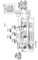
- FIG. 1 is a diagram illustrating an example of the overall configuration of the system.
- FIG. 2 is a diagram for explaining the effect of the system.
- FIG. 3 is a diagram illustrating the configuration of the border router.
- FIG. 4 is a diagram illustrating an example of the NAT table of the border router.
- FIG. 5 is a diagram illustrating an example of setting change in the NAT table of the border router.
- FIG. 6 is a diagram showing the configuration of the DNS server.
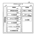
- FIG. 7 is a diagram illustrating the configuration of the cloud controller.
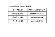
- FIG. 8 is a diagram illustrating an example of global IP address band information.
- FIG. 9 is a diagram illustrating a configuration of the redirect device.
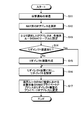
- FIG. 10 is a flowchart showing the processing procedure of the cloud controller.
- FIG. 11 is a flowchart illustrating a processing procedure of the redirect device.
- FIG. 12 is a diagram for explaining VM migration.
- FIG. 13 is a diagram illustrating a computer that executes a control
- the system includes a data center (data centers 1, 2 and 3), user terminals 10 (10A to 10E), a DNS (Domain Name System) server 40, and a cloud controller (control device) 50. These are connected by a network 60 such as the Internet.
- a network 60 such as the Internet.
- Each data center includes a border router 30 and one or more VMs can be installed.
- the data center 1 includes a border router 30A
- the data center 2 includes a border router 30B
- the data center 3 includes a border router 30C.
- a case where a device installed in the data center is a VM (Virtual Machine) will be described as an example, but a device other than a VM may be used.
- VM Virtual Machine
- Border router 30 (30A, 30B, 30C) is connected to network 60 and relays communication between user terminal 10 and each VM in each data center.
- Each border router 30 divides the data centers 1, 2, and 3 configured by the virtual L2 (layer 2) network 21 into the same common network segment 22 and network 60.
- the interface 31 of the border router 30A has an IP address (global IP address) “aaa.bbb.ccc.” Selected from the IP address band “aaa.bbb.ccc.0 / 24” assigned to the data center 1. 101 "is set. Similarly, an IP address selected from the IP address band assigned to the data center 2 to which the border router 30B belongs is set in the border router 30B, and the data center 3 to which the border router 30C belongs is also set in the border router 30C. An IP address selected from the IP address band assigned to is set.
- the border router 30 has a NAT (Network Address Translation) function, and performs mutual conversion between a global IP address and a private IP address of each VM using a NAT table (see FIG. 4). For example, a case where “xxx.yyy.zzz.0 / 24” is assigned as the private IP address space inside the data center 1 and the private IP address of the VM (A) is “xxx.yyy.zzz.101”. Think. In this case, when the border router 30A receives the packet addressed to the VM (A), the border IP address (for example, “aaa.bbb.ccc.101”) of the packet destination is used as the private IP address of the VM (A).
- the border IP address for example, “aaa.bbb.ccc.101”
- Xxx.yyy.zzz.101 transfer to the VM (A) inside the data center 1.
- Each data center is connected by a virtual L2 (layer 2) network 21, and any border router 30 can use the NAT table to transfer the packet to the destination VM when receiving the packet. .
- the border router 30 also has a function as a so-called FW (FireWall), and performs filtering of attack packets when an attack such as a DDoS attack is detected. Further, the border router 30 notifies the cloud controller 50 that an attack has been detected.
- the border router 30 may be realized by a physical machine or a virtual machine.
- the VM executes communication with the user terminal 10 via the virtual L2 network 21 and the border router 30.
- the VM is a virtual machine that executes, for example, a Web server or a DB (database) server.
- This VM is realized by physical resources installed in the data center.
- the physical resources are a communication interface, a processor, a memory, a hard disk, and the like.
- an attack on the VM (A) of the data center 1 occurs and the host name of this VM (A) is “hoge.example.co.jp”.
- a redirect device 70 is installed in the data center. When the redirect device 70 receives an access from the user terminal 10, the redirect device 70 redirects to a predetermined redirect destination.
- the redirect device 70 is expressed as being installed in the data setter 1, but may be installed in the data centers 2 and 3.
- the redirect device 70 may be realized by a VM or a physical machine. Furthermore, it may be realized by mounting the function of the redirect device 70 on the border router 30.
- the border router 30, the VM, and the redirect device 70 in each data center are connected to the virtual L2 network 21 by a virtual switch (not shown).
- the virtual L2 network 21 is a logical L2 network that connects the data centers.
- the virtual L2 network 21 may be realized by a so-called virtualization technique or may be realized by other techniques.
- the user terminal 10 accesses equipment (for example, VM) in each data center via the network 60 and receives provision of various services from the VM.
- the user terminal 10 is, for example, a personal computer or a smartphone.
- the DNS server 40 performs host name resolution. For example, when the DNS server 40 receives a request for name resolution of the host name of the access destination VM from the user terminal 10, the DNS server 40 returns an IP address corresponding to the host name. For example, the DNS server 40 refers to the DNS information held by itself (see reference numeral 102) and returns the IP address “aaa.bbb.ccc.101” for “hoge.example.co.jp”. And the user terminal 10 accesses VM (for example, VM (A)) using the said IP address.
- VM for example, VM (A)
- This DNS information includes the case where each VM (eg, VM (A)) is attacked in addition to the IP address (global IP address) for the host name of each VM (eg, VM (A)). An IP address for the redirect destination host name is set.
- the DNS information indicated by reference numeral 102 in FIG. 1 includes VM (A) in addition to the IP address “aaa.bbb.ccc.101” for the host name “hoge.example.co.jp” of VM (A).
- the host name of the redirect destination when IP is attacked and the IP address for the host name are set.
- the redirect destination when the VM (A) is attacked is the border router 30B of the data center 2 or the border router 30C of the data center 3.
- the IP address for the host name “hoge.anti_ddos1.example.co.jp” is “ddd.eee.fff.101 (VM (set in the border router 30B ( A) global IP address) ”, and the IP address corresponding to the host name“ hoge.anti_ddos2.example.co.jp ”is“ ggg.hhh.iii.101 ”(the global IP address of the VM (A) set in the border router 30C). IP address) ”is set. Accordingly, the user terminal 10 that has received the redirect from the redirect device 70 (details will be described later) can perform name resolution of the redirect destination host name.
- the cloud controller 50 controls each device in the data center (for example, the border router 30, the VM, and the redirect device 70). For example, the cloud controller 50 changes the setting of the NAT IP address and the setting of the NAT table for the other border router 30. In addition, the cloud controller 50 performs redirection settings for the redirect device 70.
- the border router 30A of the data center 1 detects a DDoS attack on the VM (A)
- the border router 30A of the data center 1 detects a DDoS attack (S1)
- it notifies the cloud controller 50 of the detection of the DDoS attack (S2).
- the cloud controller 50 selects a NAT IP address from the global IP address band assigned to each of the data centers 2 and 3 (S3).
- the cloud controller 50 performs NAT setting for each border router 30 (S4). That is, the cloud controller 50 sets the global IP address and private IP address of the VM (A) selected in S3 in the NAT tables of the border routers 30B and 30C.
- the cloud controller 50 sets the global IP address “ddd.eee.fff.101” of the VM (A) selected in S3 and the private IP address of the VM (A) in the NAT table of the border router 30B. Further, the cloud controller 50 sets the global IP address “ggg.hhh.iii.101” of the VM (A) selected in S3 and the private IP address of the VM (A) in the NAT table of the border router 30C.
- the cloud controller 50 sets redirection in the redirect device 70 (S5). For example, when the redirect device 70 receives access from the user terminal 10 to the redirect device 70, the cloud controller 50 performs URL2 (hoge.anti_ddos1.example.co.jp) and URL3 (hoge.anti_ddos2.example.co). .jp) to redirect to one of the settings.
- URL2 and URL3 are host names of redirect destinations when the VM (A) described in the DNS information of the DNS server 40 is attacked.
- the cloud controller 50 acquires the redirect destination host name from, for example, the DNS information of the DNS server 40.
- the cloud controller 50 creates (prepares) the redirect device 70 using the resources in the data center, and performs the above-described redirect setting.
- the private IP address of the redirect device 70 is a private IP address (for example, “xxx.yyy.zzz.102”) that is free from a predetermined private IP address space (for example, “xxx.yyy.zzz.0 / 24”). ]) To assign.
- the cloud controller 50 changes the NAT setting of the border router 30A (S6). That is, the private IP address for the global IP address of the VM (A) in the NAT table of the border router 30A is changed from the private IP address of the VM (A) to the private IP address (for example, “xxx.yyy.zzz. 102 ”).
- the user terminal 10 for example, the user terminals 10D and 10E of the authorized user first accesses the redirect device 70, but is redirected, and the DNS server 40 sets the redirect destination host name. Name resolution is performed, and the VM (A) is accessed via the border router 30B or border router 30C.
- the user terminal 10 for example, the user terminals 10D and 10E of the authorized user uses the redirect device 70 to either URL2 (hoge.anti_ddos1.example.co.jp) or URL3 (hoge.anti_ddos2.example.co.jp).
- the user terminal 10 of the authorized user is sent to the URL 2 (hoge.anti_ddos1.example.co.jp) or URL3 (hoge.anti_ddos2.example.co.jp) by the DNS server 40.
- the IP address (“ddd.eee.fff.101”, “ggg.hhh.iii.101”) is known
- the VM (A) is accessed via the border router 30B or the border router 30C based on this IP address.
- the attacker's user terminal 10 for example, the user terminals 10A, 10B, and 10C
- an attack program attack tool
- the redirect device 70 continues to be attacked to the original IP address (“aaa.bbb.ccc.101”) via the border router 30A.
- the user terminal 10 of the authorized user accesses the VM (A) by avoiding the border router 30A where access is concentrated, so even when an attack occurs. It becomes easy to access VM (A). Further, since the concentration of access to the border router 30A is alleviated, it is possible to reduce the bandwidth pressure on the border router 30A. As a result, the system can continue to provide services to the user terminal 10 even when subjected to an attack such as a DDoS attack.
- the border router 30 is connected to the network 60 and relays communication between the user terminal 10 and each VM in each data center.
- the border router 30 includes interfaces 31 and 34, a storage unit 32, and a control unit 33.
- the interface 31 is an interface that connects the border router 30 and the network 60.
- a global IP address selected from the IP address band of the data center to which the border router 30 belongs is set.
- the interface 34 is an interface that connects the border router 30 to the virtual L2 network 21 and the VM.
- the storage unit 32 stores a NAT table.
- the NAT table is information in which a global IP address and a private IP address of a device (for example, VM) in the data center are associated with each other.
- the NAT table shown in FIG. 4 is a NAT table in the border router 30A.
- the private IP address for the global IP address “aaa.bbb.ccc.101” is “xxx.yyy.zzz.101”. Indicates that This NAT table is referred to when the route control unit 332 (described later) performs NAT.
- the NAT table is changed based on an instruction from the cloud controller 50.
- NAT table management unit 331 includes a NAT table management unit 331, a path control unit 332, an attack notification unit 333, and a filtering unit 334.
- the NAT table management unit 331 updates the NAT table (see FIG. 4) based on an instruction from the external device. For example, if there is a private IP address setting change instruction for the VM (A) global IP address from the cloud controller 50 to the NAT table, the setting of the NAT table is changed accordingly.
- the private IP address for the global IP address “aaa.bbb.ccc.101” of the VM (A) is changed to “xxx.yyy.zzz.101 (the private IP address of the VM (A)) in the NAT table. ) ”To“ xxx.yyy.zzz.102 (the private IP address of the redirect device 70) ”, the NAT table management unit 331 responds accordingly with reference numeral 301 ⁇ reference numeral in FIG. As shown in 302, the setting of the NAT table is changed.
- the path control unit 332 in FIG. 3 performs path control of packets input via the interfaces 31 and 34. For example, when a packet from the user terminal 10 to the VM is received via the interface 31, the packet is transferred to the VM. At this time, the path control unit 332 performs NAT conversion between the global IP address and the private IP address attached to the packet with reference to the NAT table (see FIG. 4).
- the attack notification unit 333 When the attack notification unit 333 detects an attack such as a DDoS attack on the VM via its own border router 30, the attack notification unit 333 notifies the cloud controller 50 that the attack has been detected.
- the filtering unit 334 performs filtering of attack packets.
- the filtering unit 334 refers to the header information of the received packet and discards the packet estimated as the attack packet.
- this boundary router 30 was demonstrated as what is implement
- the DNS server 40 performs name resolution of the host name of the access destination.
- the DNS server 40 includes a communication control unit 41, a storage unit 42, and a control unit 43.
- the communication control unit 41 controls communication with other devices.
- the communication control unit 41 controls communication performed with the user terminal 10 or the like.
- the storage unit 42 stores DNS information.
- This DNS information includes information on an IP address (global IP address) corresponding to the host name.
- This DNS information is referred to when the host name resolution unit 432 (described later) performs host name resolution.
- This DNS information is, for example, information indicated by reference numeral 102 in FIG.
- the control unit 43 includes a DNS information management unit 431 and a host name resolution unit 432.
- the DNS information management unit 431 sets DNS information based on an instruction from an external device (for example, the cloud controller 50). For example, as indicated by reference numeral 102 in FIG. 1, the DNS information is set to “aaa.bbb.ccc.101” as the IP address for the host name “hoge.example.co.jp” of the VM (A). The IP address “ddd.eee.fff.101” for the name “hoge.anti_ddos1.example.co.jp” is set, and “ggg.hhh. iii.101 "is set.
- a pair of a VM host name and an IP address used when an attack against this VM is detected is set.
- an IP address corresponding to the VM host name used when an attack against this VM is detected an IP address under the border router 30 of a base other than the base to which the target VM belongs is used.
- the host name of the VM used when an attack on the VM is detected is referred to when the redirect setting unit 533 (described later) sets redirection for the redirect device 70.
- anti_ddos1 and “anti_ddos2” included in the above host names are character strings used for simplifying the description, and are actually character strings that can be understood by the attacker as a countermeasure against DDoS. Is not used.
- the host name resolution unit 432 refers to the DNS information and performs host name resolution. For example, when receiving a request for name resolution of the host name of the VM (A) from the user terminal 10, the host name resolution unit 432 refers to the DNS information and returns an IP address corresponding to the host name.
- the cloud controller 50 controls each device (for example, the border router 30, the VM, the redirect device 70, etc.) in the data center.
- the cloud controller 50 controls each device (for example, the border router 30, the VM, the redirect device 70, etc.) in the data center.
- the cloud controller 50 includes a communication control unit 51, a storage unit 52, and a control unit 53.
- the communication control unit 51 controls communication with other devices.
- the communication control unit 51 controls communication performed with the border router 30 and the DNS server 40.
- the storage unit 52 stores border router information and global IP address band information.
- the border router information is information indicating the data center to which the border router 30 belongs and the IP address of the border router 30 for each border router 30.
- Global IP address band information is information indicating a global IP address band assigned to each data center.
- the global IP address band assigned to the data center 1 is “aaa.bbb.ccc.0 / 24”
- the global IP address band assigned to the data center 2 Indicates “ddd.eee.fff.0 / 24”.
- This global IP address band information is referred to when the NAT setting unit 532 (described later) sets NAT for each border router 30.
- the control unit 53 includes an attack notification receiving unit 531, a NAT setting unit 532, a redirect setting unit 533, and a NAT changing unit 534.
- the migration execution unit 535 and the DNS information setting unit 536 indicated by broken lines may be equipped or not equipped, and the case where they are equipped will be described later.
- the attack notification receiving unit 531 receives an attack notification from the border router 30.
- the NAT setting unit 532 sets the NAT of the attack target VM for the border router 30 of each data center.
- the NAT setting unit 532 selects the NAT IP address of the VM (A) with reference to the global IP address band information (see FIG. 8) for each border router 30 of the data centers 2 and 3. .
- the NAT setting unit 532 refers to the global IP address band information (see FIG. 8), and from the global IP address band “ddd.eee.fff.0 / 24” assigned to the data center 2, “ddd.
- the NAT setting unit 532 sets the NAT setting in which “ddd.eee.fff.101” is associated with the private IP address (for example, “xxx.yyy.zzz.101”) of the VM in the data center 2.
- the border router 30B sets the NAT setting in which “ddd.eee.fff.101” is associated with the private IP address (for example, “xxx.yyy.zzz.101”) of the VM in the data center 2.
- the NAT setting unit 532 sets the NAT setting in which “ggg.hhh.iii.101” is associated with the private IP address of the VM (for example, “xxx.yyy.zzz.101”) in the data center 3. To the border router 30C. Note that the NAT setting unit 532 stores the IP address of each VM already set in the NAT in the storage unit 52 so that there is no IP address duplication between VMs in the NAT setting.
- the redirect setting unit 533 sets redirection for the redirect device 70.
- the redirect setting unit 533 detects an attack on this VM (A) from the DNS information of the DNS server 40 (see reference numeral 102 in FIG. 1).
- the VM host name (“hoge.anti_ddos1.example.co.jp" and "hoge.anti_ddos2.example.co.jp") used at the time of acquisition is acquired, and one of the acquired hosts is transmitted to the redirect device 70. Set redirect to name host.
- the access from the user terminal 10 (the user terminal 10 of the authorized user) to the redirect device 70 is to either “hoge.anti_ddos1.example.co.jp” or “hoge.anti_ddos2.example.co.jp”. Redirected.
- the user terminal 10 (user terminal 10 of a regular user) accesses the VM (A) via the border router 30B or the border router 30C.
- the redirect setting unit 533 may also set a redirect destination selection method (for example, round robin) in the redirect device 70.
- the redirect setting unit 533 creates the redirect device 70 (for example, the redirect VM), for example, in the data center to which the attack target VM belongs. Then, the redirect setting described above is performed for the created redirect device 70. Since the data centers are connected by the virtual L2 network 21, the redirect setting unit 533 may create the redirect device 70 in addition to the data center to which the attack target VM belongs. By creating the redirect device 70 in the data center to which it belongs, it is possible to avoid that the attack packet communicates between the data centers.
- the NAT changing unit 534 changes the private IP address of the VM in the NAT table of the border router 30 of the data center to which the attack target VM belongs to the private IP address of the redirect device 70. .
- the NAT changing unit 534 has the private IP address of the VM (A) in the NAT table of the border router 30A of the data center 1 to which the VM (A) belongs. Is changed to the private IP address of the redirect device 70 (see S6 in FIG. 1). As a result, the traffic addressed to the VM (A) via the border router 30A reaches the redirect device 70.
- the redirect device 70 redirects access from the user terminal 10.
- the redirect device 70 includes a communication control unit 71, a storage unit 72, and a control unit 73.
- the communication control unit 71 controls communication with other devices. For example, the communication control unit 71 controls communication performed with the cloud controller 50 and the user terminal 10.
- the storage unit 72 stores redirect destination information.
- This redirect destination information is information indicating the host name of the redirect destination of the redirect device 70. For example, “hoge.anti_ddos1.example.co.jp”, “hoge.anti_ddos2.example.co.jp”, etc. are described.
- the control unit 73 includes a redirect setting reception unit 731 and a redirect unit 732.
- the redirect setting reception unit 731 When the redirect setting reception unit 731 receives the redirect setting from the cloud controller 50 via the communication control unit 71, the redirect setting reception unit 731 outputs the redirect destination information (redirect destination host name) included in the redirect setting to the storage unit 72.
- the redirect unit 732 performs HTTP redirect (redirect) of access from the user terminal 10. For example, when the redirect unit 732 accepts access from the user terminal 10 via the communication control unit 71, the host name (for example, “hoge.anti_ddos1.example.co.jp” and “hoge.anti_ddos2” indicated in the redirect destination information is received. .example.co.jp ”) to the host name determined by round robin. The redirect unit 732 determines the redirect destination by round robin as described above, so that traffic from the user terminal 10 of the authorized user to the attack target VM (for example, VM (A)) is the border router of each data center. 30.
- VM for example, VM (A)
- the NAT setting unit 532 refers to the global IP address band information (see FIG. 7) and refers to the VM.
- the NAT IP address is selected (S12).
- the NAT setting unit 532 sets the IP address selected in S12 in the NAT table of each border router 30 (the border router 30 of each data center other than the data center to which the attack target VM belongs) (S13).
- the redirect setting unit 533 checks whether or not there is the redirect device 70 in the data center to which the attack target VM belongs (S14).
- the redirect setting unit 533 70 is created (S15). Then, the process proceeds to S16. On the other hand, if there is the redirect device 70 in the data center to which the attack target VM belongs (Yes in S14), the redirect setting unit 533 skips S15 and proceeds to S16.
- the redirect setting unit 533 performs the redirect setting for the redirect device 70.
- the redirect setting unit 533 uses the host name (“hoge.”) Of the VM to be used when an attack against the attack target VM (for example, VM (A)) is detected from the DNS information of the DNS server 40 (see reference numeral 102 in FIG. 1). anti_ddos1.example.co.jp ”and“ hoge.anti_ddos2.example.co.jp ”), and the redirect device 70 is set to redirect to one of the acquired host names.
- the NAT changing unit 534 changes the private IP address of the attack target VM in the NAT setting of the border router 30 of the data center to which the attack target VM belongs to the private IP address of the redirect device 70 (S17). ).
- the redirect unit 732 of the redirect device 70 determines the redirect destination host from the host indicated in the redirect destination information by round robin (S22). Access is redirected to the host determined in S22 (S23). On the other hand, before the redirect unit 732 accepts access from the user terminal 10 (No in S21), the process returns to S21.
- the access to the attack target VM is redirected by the redirect device 70 from the user terminal 10 of the authorized user.
- the user terminal 10 of the authorized user performs name resolution of the redirect destination host name by the DNS server 40
- the attack target VM is routed via the border router 30 of the data center other than the data center to which the attack target VM belongs. Will be accessing.
- the attacker's user terminal 10 cannot access the redirect device 70 even if it accesses the redirect device 70, and therefore remains in the state of accessing the redirect device 70.
- the user terminal 10 of the authorized user accesses the attack target VM by avoiding the border router 30 where access is concentrated due to the attack, it becomes easy to access the attack target VM. Moreover, since the concentration of access to the border router 30 of the data center to which the attack target VM belongs is relieved by the redirection, the bandwidth compression of the border router 30 can be reduced. As a result, the system can continue to provide services to the user terminal 10 even when subjected to an attack such as a DDoS attack.
- the bandwidth of the access line connecting each data center and the network 60 is 10 Gbps
- the total attack traffic from the attacker's user terminals 10 (10A, 10B, 10C) is 8 Gbps
- the user terminal 10 (10D) of the regular user , 10E) the total traffic from 4 Gbps is considered
- the case where the VM responds with 2 Mbytes of data in response to one request is considered as an example.
- the bandwidth of the access line connecting the data center 1 and the network 60 is 10 Gbps, the traffic for 2 Gbps including the traffic from the user terminal 10 of the authorized user is discarded.
- the traffic from the user terminal 10 (10D, 10E) of the authorized user is distributed to the border routers 30 of the two data centers (data centers 2, 3).
- the traffic to the border router 30A of the data center 1 is 8 Gbps
- the traffic to the border router 30B of the data center 2 is 2 Gbps
- the traffic to the border router 30C of the data center 3 is 2 Gbps. That is, since it becomes 10 Gbps or less, the traffic is not discarded, and the traffic from the user terminal 10 of the authorized user can be protected.
- the redirect device 70 transmits the redirect information to the user terminal 10, the traffic volume to the user terminal 10 is reduced as compared with the case where data (2 M bytes in the above example) is responded to the user terminal 10 by the VM or the like. Can be reduced.
- the redirect device 70 performs the redirect process as a main process, resources such as a CPU (Central Processing Unit), a memory, and the like are smaller than an ordinary web server for access from the user terminal 10 or the like. As a result, the redirect device 70 can cope with access from many user terminals 10. It is also effective against DDoS attacks performed on VM resources.
- the access from the attacker's user terminal 10 does not reach the attack target VM due to the change of the NAT setting in the border router 30 and the redirect by the redirect device 70. Therefore, since the VM to be attacked only needs to cope with access from the user terminal 10 of the authorized user, it can cope with the DDoS attack performed on the VM resources as described above.
- the system sets DNS information in the DNS server 40 before detecting an attack. Therefore, for example, as in the technique described in Non-Patent Document 7, the system can deal with the attack more quickly than when the DNS information of the DNS server is changed after the attack is detected.
- the attack target VM may be migrated to another data center (for example, the data center 2).
- the cloud controller 50 includes a migration execution unit 535 illustrated in FIG. 7, and the migration execution unit 535 executes migration of the VM.
- the migration execution unit 535 of the cloud controller 50 migrates the attack target VM (A) from the data center 1 to the data center 2 as shown in FIG.
- the user terminal 10 of the authorized user who has accessed the VM (A) via the border router 30B or the border router 30C does not need to communicate with the data center 1, so the VM (A ) Can be shortened.
- the cloud controller 50 performs NAT setting for each border router 30 and changes the NAT of the border router 30 of the data center to which the attack target VM belongs, by the redirect device 70 according to the same processing procedure as described above. Is executed.
- the border router 30 transmits an attack notification when it detects a DDoS attack
- the present invention is not limited to this.
- the attack notification may be transmitted when a packet to the VM relayed by the border router 30 is transmitted exceeding a predetermined threshold.
- a threshold value for example, a bandwidth value set in the interface 31 connected from the border router 30 to the network 60 is used.
- the redirect setting unit 533 of the cloud controller 50 acquires the host name of the redirect destination set in the redirect device 70 from the DNS information of the DNS server 40
- the present invention is not limited to this.
- the cloud controller 50 sets the DNS information of the DNS server 40
- the cloud controller 50 stores the DNS information set in the DNS server 40 in the storage unit 52.
- the cloud controller 50 acquires the redirect destination host name from the DNS information in the storage unit 52 and sets it in the redirect device 70.
- the cloud controller 50 further includes a DNS information setting unit 536 (see FIG. 7) for setting DNS information of the DNS server 40, and the DNS information setting unit 536 stores the DNS information set in the DNS server 40 in the storage unit 52. Keep it.
- the redirect setting unit 536 acquires the host name of the host under the border router 30 at any base other than the base to which the attack target VM belongs from the DNS information in the storage unit 52, and redirects the host with the host name.
- the redirect device 70 is set as the previous host.
- program It is also possible to create and execute a program in which processing executed by the cloud controller 50 according to the above embodiment is described in a language that can be executed by a computer. In this case, the same effect as the above-described embodiment can be obtained by the computer executing the program. Further, such a program may be recorded on a computer-readable recording medium, and the program recorded on the recording medium may be read by the computer and executed to execute the same processing as in the above embodiment.
- a computer that executes a control program that realizes the same function as the cloud controller 50 will be described.
- FIG. 13 is a diagram illustrating a computer that executes a control program.
- the computer 1000 includes, for example, a memory 1010, a CPU 1020, a hard disk drive interface 1030, a disk drive interface 1040, a serial port interface 1050, a video adapter 1060, and a network interface 1070. These units are connected by a bus 1080.
- the memory 1010 includes a ROM (Read Only Memory) 1011 and a RAM (Random Access Memory) 1012.
- the ROM 1011 stores a boot program such as BIOS (Basic Input Output System).
- BIOS Basic Input Output System
- the hard disk drive interface 1030 is connected to the hard disk drive 1090.
- the disk drive interface 1040 is connected to the disk drive 1100.
- a removable storage medium such as a magnetic disk or an optical disk is inserted into the disk drive 1100, for example.
- a mouse 1110 and a keyboard 1120 are connected to the serial port interface 1050.
- a display 1130 is connected to the video adapter 1060.
- the hard disk drive 1090 stores, for example, an OS 1091, an application program 1092, a program module 1093, and program data 1094.
- Each table described in the above embodiment is stored in the hard disk drive 1090 or the memory 1010, for example.
- control program is stored in the hard disk drive 1090 as a program module in which a command executed by the computer 1000 is described, for example.
- a program module describing each process executed by the cloud controller 50 described in the above embodiment is stored in the hard disk drive 1090.
- data used for information processing by the control program is stored in the hard disk drive 1090 as program data, for example.
- the CPU 1020 reads out the program module 1093 and the program data 1094 stored in the hard disk drive 1090 to the RAM 1012 as necessary, and executes the above-described procedures.
- the program module 1093 and the program data 1094 related to the control program are not limited to being stored in the hard disk drive 1090.
- the program module 1093 and the program data 1094 are stored in a removable storage medium and read by the CPU 1020 via the disk drive 1100 or the like. May be.
- the program module 1093 and the program data 1094 related to the control program are stored in another computer connected via a network such as a LAN (Local Area Network) or a WAN (Wide Area Network), and via the network interface 1070. It may be read by the CPU 1020.
- LAN Local Area Network
- WAN Wide Area Network
Abstract
Description
まず、図1を用いて本実施形態の制御システム(システム)の全体構成を説明する。システムは、データセンタ(データセンタ1,2,3)と、ユーザ端末10(10A~10E)と、DNS(Domain Name System)サーバ40と、クラウドコントローラ(制御装置)50とを備える。これらは、インターネット等のネットワーク60で接続される。 (overall structure)
First, the overall configuration of the control system (system) of this embodiment will be described with reference to FIG. The system includes a data center (
次に、引き続き図1を用いて、上記のシステムにおける動作概要を説明する。ここでは、データセンタ1の境界ルータ30Aが、VM(A)に対するDDoS攻撃を検知した場合を例に説明する。例えば、データセンタ1の境界ルータ30AがDDoS攻撃を検知すると(S1)、クラウドコントローラ50へDDoS攻撃の検知を通知する(S2)。この通知を受けたクラウドコントローラ50は、データセンタ2,3それぞれに割り当てられたグローバルIPアドレス帯から、NAT用のIPアドレスを選択する(S3)。そして、クラウドコントローラ50は、各境界ルータ30にNATの設定を行う(S4)。つまり、クラウドコントローラ50は、境界ルータ30B,30CそれぞれのNATテーブルにS3で選択したVM(A)のグローバルIPアドレスとプライベートIPアドレスとを設定する。 (Overview of operation)
Next, the operation outline in the above system will be described with reference to FIG. Here, a case where the
次に、システムの各構成要素を詳細に説明する。まず、図3を用いて境界ルータ30を説明する。 (Border router)
Next, each component of the system will be described in detail. First, the
次に、図6を用いてDNSサーバ40を説明する。DNSサーバ40は、前記したとおり、アクセス先のホスト名の名前解決を行う。このDNSサーバ40は、通信制御部41と、記憶部42と、制御部43とを備える。 (DNS server)
Next, the
次に、図7を用いてクラウドコントローラ50を説明する。クラウドコントローラ50は、前記したとおりデータセンタ内の各機器(例えば、境界ルータ30、VM、リダイレクト装置70等)の制御を行う。 (Cloud controller)
Next, the
次に、図9を用いて、リダイレクト装置70を説明する。前記したとおりリダイレクト装置70は、ユーザ端末10からのアクセスをリダイレクトする。このリダイレクト装置70は、通信制御部71と、記憶部72と、制御部73とを備える。 (Redirect device)
Next, the
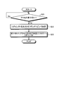
次に、図10を用いてクラウドコントローラ50の処理手順を説明する。クラウドコントローラ50の攻撃通知受信部531は、境界ルータ30からVMへの攻撃通知を受信すると(S11)、NAT設定部532は、グローバルIPアドレス帯情報(図7参照)を参照して、当該VMのNAT用のIPアドレスを選択する(S12)。そして、NAT設定部532は、S12で選択したIPアドレスを、各境界ルータ30(攻撃対象のVMの属するデータセンタ以外の各データセンタの境界ルータ30)のNATテーブルに設定する(S13)。その後、リダイレクト設定部533は攻撃対象のVMの属するデータセンタにリダイレクト装置70があるか否かを確認し(S14)、リダイレクト装置70がなければ(S14でNo)、リダイレクト設定部533はリダイレクト装置70を作成する(S15)。そして、S16へ進む。一方、リダイレクト設定部533は攻撃対象のVMの属するデータセンタにリダイレクト装置70があれば(S14でYes)、S15をスキップして、S16へ進む。 (Processing procedure)
Next, the processing procedure of the
システムが上記の処理を行うことで、正規ユーザのユーザ端末10から、攻撃対象のVMへのアクセスはリダイレクト装置70によりリダイレクトされる。そして、正規ユーザのユーザ端末10は、DNSサーバ40によりリダイレクト先のホスト名の名前解決を行うと、攻撃対象のVMの属するデータセンタ以外のデータセンタの境界ルータ30を経由して攻撃対象のVMにアクセスすることになる。一方、攻撃者のユーザ端末10は、リダイレクト装置70にアクセスしてもリダイレクトに対応できないため、リダイレクト装置70にアクセスしたままの状態となる。 (effect)
When the system performs the above processing, the access to the attack target VM is redirected by the
なお、クラウドコントローラ50が上記のようにリダイレクト装置70によるリダイレクトの設定を行った後、攻撃対象のVMを、他のデータセンタ(例えば、データセンタ2)にマイグレーションさせてもよい。この場合、クラウドコントローラ50は、図7に示すマイグレーション実行部535を備え、このマイグレーション実行部535により当該VMのマイグレーションを実行する。 (Other embodiments)
Note that after the
また、上記実施形態に係るクラウドコントローラ50が実行する処理をコンピュータが実行可能な言語で記述したプログラムを作成し、実行することもできる。この場合、コンピュータがプログラムを実行することにより、上記実施形態と同様の効果を得ることができる。さらに、かかるプログラムをコンピュータに読み取り可能な記録媒体に記録して、この記録媒体に記録されたプログラムをコンピュータに読み込ませて実行することにより上記実施形態と同様の処理を実現してもよい。以下に、クラウドコントローラ50と同様の機能を実現する制御プログラムを実行するコンピュータの一例を説明する。 (program)
It is also possible to create and execute a program in which processing executed by the
10 ユーザ端末
21 仮想L2ネットワーク
22 ネットワークセグメント
30 境界ルータ
31,34 インタフェース
32,42,52,72 記憶部
33,43,53,73 制御部
40 DNSサーバ
41,51,71 通信制御部
50 クラウドコントローラ
60 ネットワーク
331 NATテーブル管理部
332 経路制御部
333 攻撃通知部
334 フィルタリング部
431 DNS情報管理部
432 ホスト名解決部
531 攻撃通知受信部
532 NAT設定部
533 リダイレクト設定部
534 NAT変更部
535 マイグレーション実行部
536 DNS情報設定部
731 リダイレクト設定受付部
732 リダイレクト部 1, 2, 3
Claims (10)
- 仮想ネットワークにより相互に接続される複数の拠点に設置され、当該拠点内の機器と外部ネットワークとの通信を中継する境界ルータに対し、各種制御を行う制御装置であって、
いずれかの拠点内の機器へのパケットの集中を検知したとき、
前記パケットの集中が検知された機器である攻撃対象の機器の属する拠点以外の各拠点の境界ルータに前記攻撃対象の機器のIPアドレスのNAT(Network Address Translation)設定を行うNAT設定部と、
いずれかの拠点内に設置されるリダイレクト装置に対し、前記リダイレクト装置へのアクセスを、前記攻撃対象の機器の属する拠点以外のいずれかの拠点の境界ルータ配下のホストへリダイレクトさせるよう設定するリダイレクト設定部と、
前記リダイレクトの設定後、前記攻撃対象の機器の属する拠点の境界ルータのNAT設定における前記攻撃対象の機器のプライベートIPアドレスを、前記リダイレクト装置のプライベートIPアドレスに変更するNAT変更部と
を備えることを特徴とする制御装置。 A control device that is installed at a plurality of bases connected to each other by a virtual network and performs various controls on a border router that relays communication between devices in the base and an external network,
When detecting the concentration of packets on the equipment in any of the bases,
A NAT setting unit configured to perform NAT (Network Address Translation) setting of the IP address of the attack target device on a border router of each base other than the base to which the attack target device belongs, which is a device in which the packet concentration is detected;
Redirection setting for redirect devices installed in any of the sites to redirect access to the redirect device to a host under a border router at any site other than the site to which the attacked device belongs And
A NAT changing unit that changes the private IP address of the attack target device in the NAT setting of the border router of the base to which the attack target device belongs after the redirect setting, to a private IP address of the redirect device. Control device characterized. - 前記リダイレクト設定部は、
前記機器のホスト名および前記ホスト名に対応するIPアドレスと、当該機器の属する拠点以外の拠点の境界ルータ配下のホストのホスト名および前記ホスト名に対応するIPアドレスとが設定されたDNS(Domain Name System)情報を有するDNSサーバから、前記攻撃対象の機器の属する拠点以外のいずれかの拠点の境界ルータ配下のホストのホスト名を取得し、前記リダイレクト装置に対し、前記リダイレクト装置へのアクセスを、当該ホスト名のホストへリダイレクトさせるよう設定することを特徴とする請求項1に記載の制御装置。 The redirect setting unit
DNS (Domain) in which a host name of the device and an IP address corresponding to the host name, a host name of a host under a border router of a base other than the base to which the device belongs, and an IP address corresponding to the host name are set The host name of the host under the border router at any base other than the base to which the attack target device belongs is acquired from the DNS server having the Name System) information, and the redirect apparatus is accessed by the redirect apparatus. The control apparatus according to claim 1, wherein the control apparatus is configured to redirect to a host having the host name. - 前記制御装置は、さらに、
DNS(Domain Name System)サーバに設定された、前記機器のホスト名および前記ホスト名に対応するIPアドレスと、当該機器の属する拠点以外の拠点の境界ルータ配下のホストのホスト名および前記ホスト名に対応するIPアドレスとを含むDNS情報を記憶する記憶部を備え、
前記リダイレクト設定部は、
前記DNS情報から、前記攻撃対象の機器の属する拠点以外のいずれかの拠点の境界ルータ配下のホストのホスト名を取得し、前記リダイレクト装置に対し、前記リダイレクト装置へのアクセスを、当該ホスト名のホストへリダイレクトさせるよう設定することを特徴とする請求項1に記載の制御装置。 The control device further includes:
The host name of the device and the IP address corresponding to the host name set in the DNS (Domain Name System) server, and the host name and host name of the host under the border router of the base other than the base to which the equipment belongs A storage unit for storing DNS information including a corresponding IP address;
The redirect setting unit
From the DNS information, the host name of a host under a border router at any base other than the base to which the attack target device belongs is acquired, and the redirect apparatus is given access to the redirect apparatus. The control device according to claim 1, wherein the control device is configured to be redirected to a host. - 前記リダイレクト設定部は、
前記リダイレクト装置がないとき、拠点内に前記リダイレクト装置を作成、または、拠点内の機器を前記リダイレクト装置として動作させるよう設定を行うことを特徴とする請求項1~3のいずれか1項に記載の制御装置。 The redirect setting unit
The apparatus according to any one of claims 1 to 3, wherein when there is no redirect device, the redirect device is created in a base, or a device in the base is set to operate as the redirect device. Control device. - 前記NAT変更部により、前記攻撃対象の機器の属する拠点の境界ルータのNAT設定における前記攻撃対象の機器のプライベートIPアドレスを、前記リダイレクト装置のプライベートIPアドレスに変更した後、前記攻撃対象の機器を、他の拠点へマイグレーションさせるマイグレーション実行部をさらに備えることを特徴とする請求項1~3のいずれか1項に記載の制御装置。 The NAT change unit changes the private IP address of the attack target device in the NAT setting of the border router of the base to which the attack target device belongs to the private IP address of the redirect device, and then changes the attack target device. The control apparatus according to any one of claims 1 to 3, further comprising a migration execution unit that migrates to another site.
- 前記いずれかの拠点内の機器へのパケットの集中の検知は、前記拠点の境界ルータにおいて、前記機器へのDDoS攻撃を検知した場合、予め設定された閾値を超えるパケットの受信を検知した場合、および、前記境界ルータの外部ネットワーク側のインタフェースに設定された帯域を超えるトラヒック量のパケットの受信を検知した場合、のいずれかであることを特徴とする請求項1~3のいずれか1項に記載の制御装置。 The detection of the concentration of packets to the device in any one of the bases is as follows: When detecting a DDoS attack to the device in the border router of the base, detecting reception of a packet exceeding a preset threshold value, 4. The method according to any one of claims 1 to 3, wherein when the reception of a packet having a traffic volume exceeding a bandwidth set for an interface on the external network side of the border router is detected. The control device described.
- 仮想ネットワークにより相互に接続される複数の拠点に設置され、当該拠点内の機器と外部ネットワークとの通信を中継する境界ルータに対し、各種制御を行う制御装置を備える制御システムであって、
他の装置からのアクセスをリダイレクトするリダイレクト装置を含み、
前記制御装置は、
いずれか拠点内の機器へのパケットの集中を検知したとき、
前記パケットの集中が検知された機器である攻撃対象の機器の属する拠点以外の各拠点の境界ルータに前記攻撃対象の機器のIPアドレスのNAT(Network Address Translation)設定を行うNAT設定部と、
前記リダイレクト装置に対し、前記リダイレクト装置へのアクセスを、前記攻撃対象の機器の属する拠点以外のいずれかの拠点の境界ルータ配下のホストへリダイレクトさせるよう設定するリダイレクト設定部と、
前記リダイレクトの設定後、前記攻撃対象の機器の属する拠点の境界ルータのNAT設定における前記攻撃対象の機器のプライベートIPアドレスを、前記リダイレクト装置のプライベートIPアドレスに変更するNAT変更部と
を備えることを特徴とする制御システム。 A control system including a control device that performs various controls on a border router that is installed at a plurality of bases connected to each other by a virtual network and relays communication between a device in the base and an external network,
Including a redirect device that redirects access from other devices,
The controller is
When detecting the concentration of packets on any of the devices in the base,
A NAT setting unit configured to perform NAT (Network Address Translation) setting of the IP address of the attack target device on a border router of each base other than the base to which the attack target device belongs, which is a device in which the packet concentration is detected;
A redirect setting unit for setting the redirect device to redirect access to the redirect device to a host under a border router at any base other than the base to which the attack target device belongs;
A NAT changing unit that changes the private IP address of the attack target device in the NAT setting of the border router of the base to which the attack target device belongs after the redirect setting, to a private IP address of the redirect device. Feature control system. - 前記制御システムは、さらに、
前記機器のホスト名および前記ホスト名に対応するIPアドレスと、当該機器の属する拠点以外の拠点の境界ルータ配下のホストのホスト名および前記ホスト名に対応するIPアドレスとが設定されたDNS(Domain Name System)情報を有するDNSサーバを備え、
前記リダイレクト設定部は、
前記DNSサーバから、前記攻撃対象の機器の属する拠点以外のいずれかの拠点の境界ルータ配下のホストのホスト名を取得し、前記リダイレクト装置に対し、前記リダイレクト装置へのアクセスを、当該ホスト名のホストへリダイレクトさせるよう設定することを特徴とする請求項7に記載の制御システム。 The control system further includes:
DNS (Domain) in which a host name of the device and an IP address corresponding to the host name, a host name of a host under a border router of a base other than the base to which the device belongs, and an IP address corresponding to the host name are set Name System) DNS server with information
The redirect setting unit
A host name of a host under a border router at any base other than the base to which the attack target device belongs is acquired from the DNS server, and access to the redirect apparatus is made to the redirect apparatus with respect to the host name. The control system according to claim 7, wherein the control system is configured to redirect to a host. - 仮想ネットワークにより相互に接続される複数の拠点に設置され、当該拠点内の機器と外部ネットワークとの通信を中継する境界ルータに対し、各種制御を行う制御方法であって、
いずれかの拠点内の機器へのパケットの集中を検知したとき、
前記パケットの集中が検知された機器である攻撃対象の機器の属する拠点以外の各拠点の境界ルータに前記攻撃対象の機器のIPアドレスのNAT(Network Address Translation)設定を行うステップと、
いずれかの拠点内に設置されるリダイレクト装置に対し、前記リダイレクト装置へのアクセスを、前記攻撃対象の機器の属する拠点以外のいずれかの拠点の境界ルータ配下のホストへリダクレイトさせるよう設定するステップと、
前記リダイレクトの設定後、前記攻撃対象の機器の属する拠点の境界ルータのNAT設定における前記攻撃対象の機器のプライベートIPアドレスを、前記リダイレクト装置のプライベートIPアドレスに変更するステップと
を含んだことを特徴とする制御方法。 A control method for performing various controls on a border router that is installed at a plurality of bases connected to each other by a virtual network and relays communication between a device in the base and an external network,
When detecting the concentration of packets on the equipment in any of the bases,
Performing NAT (Network Address Translation) setting of the IP address of the attack target device in a border router of each base other than the base to which the attack target device is a device in which the packet concentration is detected;
A step of setting a redirect device installed in any of the sites to redirect access to the redirect device to a host under a border router at any site other than the site to which the attack target device belongs; ,
After setting the redirect, changing a private IP address of the attack target device in a NAT setting of a border router of a base to which the attack target device belongs to a private IP address of the redirect device. Control method. - 仮想ネットワークにより相互に接続される複数の拠点に設置され、当該拠点内の機器と外部ネットワークとの通信を中継する境界ルータに対し、各種制御を行う制御プログラムであって、
いずれかの拠点内の機器へのパケットの集中を検知したとき、
前記パケットの集中が検知された機器である攻撃対象の機器の属する拠点以外の各拠点の境界ルータに前記攻撃対象の機器のIPアドレスのNAT(Network Address Translation)設定を行うステップと、
いずれかの拠点内に設置されるリダイレクト装置に対し、前記リダイレクト装置へのアクセスを、前記攻撃対象の機器の属する拠点以外のいずれかの拠点の境界ルータ配下のホストへリダイレクトさせるよう設定するステップと、
前記リダイレクトの設定後、前記攻撃対象の機器の属する拠点の境界ルータのNAT設定における前記攻撃対象の機器のプライベートIPアドレスを、前記リダイレクト装置のプライベートIPアドレスに変更するステップと
をコンピュータに実行させることを特徴とする制御プログラム。 A control program that is installed at a plurality of bases connected to each other by a virtual network and performs various controls on a border router that relays communication between devices in the base and an external network,
When detecting the concentration of packets on the equipment in any of the bases,
Performing NAT (Network Address Translation) setting of the IP address of the attack target device in a border router of each base other than the base to which the attack target device is a device in which the packet concentration is detected;
Setting the redirect device installed in any of the sites to redirect access to the redirect device to a host under a border router at any site other than the site to which the attack target device belongs; ,
After setting the redirect, causing the computer to execute the step of changing the private IP address of the attack target device in the NAT setting of the border router of the base to which the attack target device belongs to the private IP address of the redirect device. A control program characterized by
Priority Applications (5)
| Application Number | Priority Date | Filing Date | Title |
|---|---|---|---|
| AU2015313050A AU2015313050B2 (en) | 2014-09-01 | 2015-08-26 | Control device, control system, control method, and control program |
| JP2016546587A JP6181881B2 (en) | 2014-09-01 | 2015-08-26 | Control device, control system, control method, and control program |
| EP15837313.4A EP3166262B1 (en) | 2014-09-01 | 2015-08-26 | Control device, control system, control method, and control program |
| CN201580046024.3A CN106605390B (en) | 2014-09-01 | 2015-08-26 | Control device, control system, control method and control program |
| US15/503,134 US10181031B2 (en) | 2014-09-01 | 2015-08-26 | Control device, control system, control method, and control program |
Applications Claiming Priority (2)
| Application Number | Priority Date | Filing Date | Title |
|---|---|---|---|
| JP2014-176946 | 2014-09-01 | ||
| JP2014176946 | 2014-09-01 |
Publications (1)
| Publication Number | Publication Date |
|---|---|
| WO2016035644A1 true WO2016035644A1 (en) | 2016-03-10 |
Family
ID=55439709
Family Applications (1)
| Application Number | Title | Priority Date | Filing Date |
|---|---|---|---|
| PCT/JP2015/074072 WO2016035644A1 (en) | 2014-09-01 | 2015-08-26 | Control device, control system, control method, and control program |
Country Status (6)
| Country | Link |
|---|---|
| US (1) | US10181031B2 (en) |
| EP (1) | EP3166262B1 (en) |
| JP (1) | JP6181881B2 (en) |
| CN (1) | CN106605390B (en) |
| AU (1) | AU2015313050B2 (en) |
| WO (1) | WO2016035644A1 (en) |
Cited By (3)
| Publication number | Priority date | Publication date | Assignee | Title |
|---|---|---|---|---|
| CN106302525A (en) * | 2016-09-27 | 2017-01-04 | 黄小勇 | A kind of cyberspace security defend method and system based on camouflage |
| JP2017204721A (en) * | 2016-05-11 | 2017-11-16 | アライドテレシス株式会社 | Security system |
| JP2018038083A (en) * | 2017-11-21 | 2018-03-08 | アライドテレシス株式会社 | Security system |
Families Citing this family (2)
| Publication number | Priority date | Publication date | Assignee | Title |
|---|---|---|---|---|
| US10397071B2 (en) * | 2016-01-05 | 2019-08-27 | Airmagnet, Inc. | Automated deployment of cloud-hosted, distributed network monitoring agents |
| US11811656B2 (en) * | 2021-01-15 | 2023-11-07 | Vmware, Inc. | Direct communication between endpoints across remote sites |
Citations (2)
| Publication number | Priority date | Publication date | Assignee | Title |
|---|---|---|---|---|
| JP2004334455A (en) * | 2003-05-07 | 2004-11-25 | Fujitsu Ltd | Server device |
| JP2011221993A (en) * | 2010-04-12 | 2011-11-04 | Wins Technet Co Ltd | System for preventing normal user being blocked in nat network web service and method for controlling the same |
Family Cites Families (10)
| Publication number | Priority date | Publication date | Assignee | Title |
|---|---|---|---|---|
| CN101030889A (en) * | 2007-04-18 | 2007-09-05 | 杭州华为三康技术有限公司 | Method and apparatus against attack |
| US20080320116A1 (en) * | 2007-06-21 | 2008-12-25 | Christopher Briggs | Identification of endpoint devices operably coupled to a network through a network address translation router |
| CN102316082A (en) * | 2010-07-06 | 2012-01-11 | 杭州华三通信技术有限公司 | Method and flow cleaning equipment for defensing website distributed denial of service (DDoS) attack |
| KR101095447B1 (en) | 2011-06-27 | 2011-12-16 | 주식회사 안철수연구소 | Apparatus and method for preventing distributed denial of service attack |
| CN102291390B (en) * | 2011-07-14 | 2014-06-04 | 南京邮电大学 | Method for defending against denial of service attack based on cloud computation platform |
| CN102281298A (en) * | 2011-08-10 | 2011-12-14 | 深信服网络科技(深圳)有限公司 | Method and device for detecting and defending challenge collapsar (CC) attack |
| US20130304927A1 (en) | 2012-05-14 | 2013-11-14 | King Abdulaziz City For Science And Technology | Network address translation-based method of bypassing internet access denial |
| CN103179192B (en) * | 2013-02-07 | 2015-11-25 | 杭州华三通信技术有限公司 | The message forwarding method that virtual server moves, system and NAT service equipment |
| US9407602B2 (en) * | 2013-11-07 | 2016-08-02 | Attivo Networks, Inc. | Methods and apparatus for redirecting attacks on a network |
| EP3208976B1 (en) | 2014-11-19 | 2019-09-11 | Nippon Telegraph and Telephone Corporation | Control device, control method and control program |
-
2015
- 2015-08-26 JP JP2016546587A patent/JP6181881B2/en active Active
- 2015-08-26 AU AU2015313050A patent/AU2015313050B2/en active Active
- 2015-08-26 CN CN201580046024.3A patent/CN106605390B/en active Active
- 2015-08-26 WO PCT/JP2015/074072 patent/WO2016035644A1/en active Application Filing
- 2015-08-26 EP EP15837313.4A patent/EP3166262B1/en active Active
- 2015-08-26 US US15/503,134 patent/US10181031B2/en active Active
Patent Citations (2)
| Publication number | Priority date | Publication date | Assignee | Title |
|---|---|---|---|---|
| JP2004334455A (en) * | 2003-05-07 | 2004-11-25 | Fujitsu Ltd | Server device |
| JP2011221993A (en) * | 2010-04-12 | 2011-11-04 | Wins Technet Co Ltd | System for preventing normal user being blocked in nat network web service and method for controlling the same |
Non-Patent Citations (2)
| Title |
|---|
| See also references of EP3166262A4 * |
| YUKIO NAGABUCHI ET AL.: "Proposal of loadbalancing DDoS traffic for virtual datacenters", IEICE TECHNICAL REPORT IN 2014-48, vol. 114, no. 139, 10 July 2014 (2014-07-10), pages 107 - 112, XP009500465 * |
Cited By (3)
| Publication number | Priority date | Publication date | Assignee | Title |
|---|---|---|---|---|
| JP2017204721A (en) * | 2016-05-11 | 2017-11-16 | アライドテレシス株式会社 | Security system |
| CN106302525A (en) * | 2016-09-27 | 2017-01-04 | 黄小勇 | A kind of cyberspace security defend method and system based on camouflage |
| JP2018038083A (en) * | 2017-11-21 | 2018-03-08 | アライドテレシス株式会社 | Security system |
Also Published As
| Publication number | Publication date |
|---|---|
| JP6181881B2 (en) | 2017-08-16 |
| US20170228539A1 (en) | 2017-08-10 |
| CN106605390A (en) | 2017-04-26 |
| EP3166262A1 (en) | 2017-05-10 |
| EP3166262A4 (en) | 2018-02-21 |
| EP3166262B1 (en) | 2018-08-22 |
| AU2015313050A1 (en) | 2017-02-23 |
| AU2015313050B2 (en) | 2018-05-24 |
| JPWO2016035644A1 (en) | 2017-04-27 |
| CN106605390B (en) | 2019-12-03 |
| US10181031B2 (en) | 2019-01-15 |
Similar Documents
| Publication | Publication Date | Title |
|---|---|---|
| US10904204B2 (en) | Incompatible network gateway provisioned through DNS | |
| US9319315B2 (en) | Distributing transmission of requests across multiple IP addresses of a proxy server in a cloud-based proxy service | |
| US10356097B2 (en) | Domain name system and method of operating using restricted channels | |
| US11863448B2 (en) | Method and apparatus for traffic optimization in virtual private networks (VPNs) | |
| JP6181881B2 (en) | Control device, control system, control method, and control program | |
| EP2745474B1 (en) | Virtualization gateway between virtualized and non-virtualized networks | |
| KR20110119534A (en) | Load-balancing via modulus distribution and tcp flow redirection due to server overload | |
| WO2016042587A1 (en) | Attack observation device and attack observation method | |
| US11438372B2 (en) | Utilizing routing advertisements to automate DDOS scrubbing techniques in a telecommunications network | |
| CN105490995A (en) | Method and device for forwarding message by NVE in NVO3 network | |
| US11562030B2 (en) | Applying filter expressions to requests at an edge server | |
| US11115435B2 (en) | Local DDOS mitigation announcements in a telecommunications network | |
| CN112968879B (en) | Method and equipment for realizing firewall management | |
| JP6215144B2 (en) | Control device, control method, and control program | |
| US9544330B1 (en) | Method of securing management interfaces of virtual machines | |
| JP2014165560A (en) | Server and program | |
| JP2019169862A (en) | Virtual router and relay program |
Legal Events
| Date | Code | Title | Description |
|---|---|---|---|
| 121 | Ep: the epo has been informed by wipo that ep was designated in this application |
Ref document number: 15837313 Country of ref document: EP Kind code of ref document: A1 |
|
| ENP | Entry into the national phase |
Ref document number: 2016546587 Country of ref document: JP Kind code of ref document: A |
|
| REEP | Request for entry into the european phase |
Ref document number: 2015837313 Country of ref document: EP |
|
| WWE | Wipo information: entry into national phase |
Ref document number: 2015837313 Country of ref document: EP |
|
| ENP | Entry into the national phase |
Ref document number: 2015313050 Country of ref document: AU Date of ref document: 20150826 Kind code of ref document: A |
|
| NENP | Non-entry into the national phase |
Ref country code: DE |