WO2016031203A1 - Display control apparatus, and display control method - Google Patents
Display control apparatus, and display control method Download PDFInfo
- Publication number
- WO2016031203A1 WO2016031203A1 PCT/JP2015/004187 JP2015004187W WO2016031203A1 WO 2016031203 A1 WO2016031203 A1 WO 2016031203A1 JP 2015004187 W JP2015004187 W JP 2015004187W WO 2016031203 A1 WO2016031203 A1 WO 2016031203A1
- Authority
- WO
- WIPO (PCT)
- Prior art keywords
- area
- region
- additional information
- unit
- frames
- Prior art date
Links
Images


Classifications
-
- H—ELECTRICITY
- H04—ELECTRIC COMMUNICATION TECHNIQUE
- H04N—PICTORIAL COMMUNICATION, e.g. TELEVISION
- H04N21/00—Selective content distribution, e.g. interactive television or video on demand [VOD]
- H04N21/40—Client devices specifically adapted for the reception of or interaction with content, e.g. set-top-box [STB]; Operations thereof
- H04N21/43—Processing of content or additional data, e.g. demultiplexing additional data from a digital video stream; Elementary client operations, e.g. monitoring of home network or synchronising decoder's clock; Client middleware
- H04N21/435—Processing of additional data, e.g. decrypting of additional data, reconstructing software from modules extracted from the transport stream
-
- G—PHYSICS
- G06—COMPUTING; CALCULATING OR COUNTING
- G06V—IMAGE OR VIDEO RECOGNITION OR UNDERSTANDING
- G06V20/00—Scenes; Scene-specific elements
- G06V20/40—Scenes; Scene-specific elements in video content
- G06V20/46—Extracting features or characteristics from the video content, e.g. video fingerprints, representative shots or key frames
-
- H—ELECTRICITY
- H04—ELECTRIC COMMUNICATION TECHNIQUE
- H04N—PICTORIAL COMMUNICATION, e.g. TELEVISION
- H04N21/00—Selective content distribution, e.g. interactive television or video on demand [VOD]
- H04N21/20—Servers specifically adapted for the distribution of content, e.g. VOD servers; Operations thereof
- H04N21/23—Processing of content or additional data; Elementary server operations; Server middleware
- H04N21/234—Processing of video elementary streams, e.g. splicing of video streams, manipulating MPEG-4 scene graphs
- H04N21/23418—Processing of video elementary streams, e.g. splicing of video streams, manipulating MPEG-4 scene graphs involving operations for analysing video streams, e.g. detecting features or characteristics
-
- H—ELECTRICITY
- H04—ELECTRIC COMMUNICATION TECHNIQUE
- H04N—PICTORIAL COMMUNICATION, e.g. TELEVISION
- H04N21/00—Selective content distribution, e.g. interactive television or video on demand [VOD]
- H04N21/40—Client devices specifically adapted for the reception of or interaction with content, e.g. set-top-box [STB]; Operations thereof
- H04N21/43—Processing of content or additional data, e.g. demultiplexing additional data from a digital video stream; Elementary client operations, e.g. monitoring of home network or synchronising decoder's clock; Client middleware
- H04N21/431—Generation of visual interfaces for content selection or interaction; Content or additional data rendering
- H04N21/4312—Generation of visual interfaces for content selection or interaction; Content or additional data rendering involving specific graphical features, e.g. screen layout, special fonts or colors, blinking icons, highlights or animations
- H04N21/4316—Generation of visual interfaces for content selection or interaction; Content or additional data rendering involving specific graphical features, e.g. screen layout, special fonts or colors, blinking icons, highlights or animations for displaying supplemental content in a region of the screen, e.g. an advertisement in a separate window
-
- H—ELECTRICITY
- H04—ELECTRIC COMMUNICATION TECHNIQUE
- H04N—PICTORIAL COMMUNICATION, e.g. TELEVISION
- H04N21/00—Selective content distribution, e.g. interactive television or video on demand [VOD]
- H04N21/40—Client devices specifically adapted for the reception of or interaction with content, e.g. set-top-box [STB]; Operations thereof
- H04N21/47—End-user applications
- H04N21/488—Data services, e.g. news ticker
-
- H—ELECTRICITY
- H04—ELECTRIC COMMUNICATION TECHNIQUE
- H04N—PICTORIAL COMMUNICATION, e.g. TELEVISION
- H04N21/00—Selective content distribution, e.g. interactive television or video on demand [VOD]
- H04N21/80—Generation or processing of content or additional data by content creator independently of the distribution process; Content per se
- H04N21/81—Monomedia components thereof
- H04N21/8126—Monomedia components thereof involving additional data, e.g. news, sports, stocks, weather forecasts
- H04N21/8133—Monomedia components thereof involving additional data, e.g. news, sports, stocks, weather forecasts specifically related to the content, e.g. biography of the actors in a movie, detailed information about an article seen in a video program
Definitions
- the present disclosure relates to a display control apparatus and a display control method for displaying additional information associated with video content using a fingerprint together with the video content.
- a communication service that uses technology to recognize content via the cloud has been proposed.
- a television receiver hereinafter referred to as “recognizing input video”, acquiring additional information related to this video via a communication network, and displaying the acquired additional information together with video content on a display screen
- TV Abbreviated as “TV”.
- a technique for recognizing an input video is called “ACR (Automatic Content Recognition)”.
- Patent Document 1 and Patent Document 2 disclose fingerprint technologies. In this technique, a contour of a face or the like reflected in an image frame in a video is detected, a fingerprint is generated based on the detected contour, and the generated fingerprint is collated with data stored in a database.
- This disclosure provides a display control apparatus and a display control method for displaying additional information on a display screen by superimposing additional information at a more appropriate position on the video content.
- the display control device is a device for displaying additional information associated with video content using a fingerprint together with the video content on a display screen.
- the display control device includes an area specifying unit, an attention area estimating unit, and a position determining unit.
- the area specifying unit specifies a first area and a second area included in an area excluding the first area in the frame in each of the plurality of frames included in the video content.
- the attention area estimation unit sets one of the first area and the second area as the attention area and the other as the non-area based on the positional relationship between the first area and the second area in each of the plurality of frames.
- the region of interest sets a position that is commonly included in each non-attention area of the plurality of frames as a position for displaying additional information.
- the display control device can superimpose additional information at a more appropriate position on the video content and display it on the display screen.
- FIG. 1 is a block diagram illustrating a configuration example of the content recognition system according to the first embodiment.
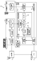
- FIG. 2 is a block diagram illustrating a configuration example of the receiving apparatus according to the first embodiment.
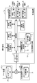
- FIG. 3 is a block diagram illustrating a configuration example of the display position control unit according to the first embodiment.
- FIG. 4 is a flowchart showing an example of content recognition processing in the first embodiment.
- FIG. 5 is a flowchart illustrating an example of the calculation process of the overlapping area information according to the first embodiment.
- FIG. 6 is a flowchart illustrating an example of the overlapping range calculation process according to the first embodiment.
- FIG. 7 is a flowchart illustrating an example of a superimposition period calculation process in the first embodiment.
- FIG. 1 is a block diagram illustrating a configuration example of the content recognition system according to the first embodiment.
- FIG. 2 is a block diagram illustrating a configuration example of the receiving apparatus according to the first embodiment.
- FIG. 3 is a block diagram
- FIG. 8 is a flowchart illustrating an example of area specifying processing according to the first embodiment.
- FIG. 9 is a flowchart illustrating an example of a determination process for determining whether there is an inclusion relationship in the first embodiment.
- FIG. 10 is a flowchart illustrating an example of a process for determining a candidate for an overlapping area according to the first embodiment.
- FIG. 11 is a diagram schematically showing a specific example of the content recognition process in the first embodiment.
- FIG. 12 is a first diagram schematically illustrating a specific example of the superimposition display permission determination process according to the first embodiment.
- FIG. 13 is a second diagram schematically illustrating a specific example of the superimposition display availability determination process according to the first embodiment.
- FIG. 14A is a diagram schematically illustrating an example of the position of the overlapping region in the first embodiment.
- FIG. 14B is a diagram schematically illustrating another example of the position of the overlapping region in the first embodiment.
- FIG. 15 is a block diagram illustrating a configuration example of the content recognition system according to the second embodiment.
- FIG. 16 is a block diagram illustrating a configuration example of a receiving apparatus according to the second embodiment.
- FIG. 17 is a flowchart illustrating an example of content recognition processing according to the second embodiment.
- FIG. 18 is a block diagram illustrating a modification of the configuration of the display control device according to the embodiment.
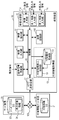
- FIG. 1 is a block diagram illustrating a configuration example of the content recognition system 1 according to the first embodiment.
- the content recognition system 1 includes a display control device for displaying additional information associated with video content using a fingerprint together with the video content.
- the content recognition system 1 includes a broadcast station 3, an STB (Set Top Box) 4, a receiving device 10, a server device 20, and an additional information server device 30.
- the server device 20 is an example of a display control device.
- Broadcast station 3 is a transmission device configured to convert video content into a video signal and broadcast it as a television broadcast signal (hereinafter also simply referred to as “broadcast signal”).
- the video content is, for example, broadcast content broadcast by wireless or wired broadcast or communication, and includes program content such as a TV program and advertisement content such as a commercial message (CM).
- CM commercial message
- the program content and the advertisement content are switched to each other as time passes.
- the broadcast station 3 transmits the video content to the STB 4 and the server device 20.
- the STB4 is a tuner / decoder for TV broadcasting.
- the STB 4 decodes the video content selected based on the user's instruction from the video signal transmitted from the broadcast station 3 and outputs the decoded video content to the receiving device 10 via the communication path.
- the communication path is, for example, HDMI (registered trademark) (High-Definition Multimedia Interface).
- the receiving device 10 is a video receiving device such as a television.
- the receiving device 10 is connected to the server device 20 and the additional information server device 30 via a communication network.
- the receiving apparatus 10 extracts a plurality of image frames (hereinafter also simply referred to as “frames”) from the received video content frame sequence, and performs image recognition on the extracted frames.
- the receiving device 10 acquires additional information from the additional information server device 30 based on the image recognition result, and displays the acquired additional information on the display screen substantially in real time together with the video.
- a frame is a picture that constitutes video content.
- the frame includes a frame in the progressive method, a field in the interlace method, and the like.
- the server device 20 is, for example, a Web server.
- the server device 20 acquires the video content transmitted from the broadcast station 3 and analyzes the acquired video content, thereby generating recognition data corresponding to the video content.
- the recognition data is, for example, data (hash value) representing video content, and is data used as a fingerprint when video content is recognized.
- the recognition data is a fingerprint generated based on a change in an image between frames.
- the server device 20 generates fingerprints for all video contents broadcast by the broadcasting station 3 and stores the fingerprints in a storage unit (not shown).
- the recognition of video content is a process of identifying video content by performing image recognition using a fingerprint.
- the additional information server device 30 is, for example, a Web server that distributes additional information related to the image recognition result by the receiving device 10.
- the additional information server device 30 is an advertisement distribution server that holds and distributes advertisements for various products.
- the server device 20 and the additional information server device 30 are Web servers that are independent of each other, but one Web server operates as the server device 20 and the additional information server device 30. Also good.
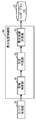
- FIG. 2 is a block diagram illustrating a configuration example of the receiving device 10 according to the first embodiment.
- FIG. 2 shows a main hardware configuration of the receiving apparatus 10.
- the receiving device 10 includes a video receiving unit 11, a video extracting unit 12, an additional information acquisition unit 13, a video output unit 14, and an image recognition unit 100. More specifically, as illustrated in FIG. 2, the reception device 10 further includes a control unit 15, an operation signal reception unit 16, and an HTTP (Hyper Text Transfer Protocol) transmission / reception unit 17.
- the additional information acquisition unit 13 illustrated in FIG. 1 includes an additional information storage unit 18 and an additional information display control unit 19.
- the control unit 15 is a processing unit configured to control each component included in the receiving device 10.
- the control unit 15 includes a nonvolatile memory, a CPU (Central Processing Unit), and a volatile memory.
- the nonvolatile memory is, for example, a ROM (Read Only Memory) or the like, and stores a program (an application program, etc.).
- the CPU is configured to execute the program.
- the volatile memory is, for example, a RAM (Random Access Memory), and is used as a temporary work area when the CPU is operating.
- the operation signal receiving unit 16 is a circuit configured to receive an operation signal output from an operation unit (not shown).
- the operation signal is a signal output from the operation unit when the user operates an operation unit (for example, a remote controller; hereinafter referred to as “remote controller”) in order to operate the receiving apparatus 10.
- the operation unit is a remote control having a gyro sensor
- the operation signal receiving unit 16 outputs information on the physical movement of the remote control itself output from the remote control (the user shakes, tilts, or changes the direction of the remote control). , Etc., may be configured to receive a signal indicating a motion when the same.
- the HTTP transmission / reception unit 17 is an interface configured to communicate with the server device 20 and the additional information server device 30 via the communication network 105.
- the HTTP transmission / reception unit 17 is a communication adapter for a wired LAN (Local Area Network) that conforms to the IEEE 802.3 standard, for example.
- the HTTP transmission / reception unit 17 acquires a fingerprint transmitted from the server device 20 via the communication network 105, and the like. The acquired fingerprint is output to the image recognition unit 100 via the control unit 15. Further, the HTTP transmission / reception unit 17 acquires additional information transmitted from the additional information server device 30 via the communication network 105, for example. The acquired additional information is stored in the additional information storage unit 18 via the control unit 15.
- the video receiver 11 includes a receiving circuit and a decoder (not shown) configured to receive video content. For example, the video receiver 11 selects a broadcast channel to be received, selects a signal input from the outside, or the like based on the operation signal received by the operation signal receiver 16.
- the video reception unit 11 includes a video input unit 11a, a first external input unit 11b, and a second external input unit 11c.
- the video input unit 11a is configured to input a video signal transmitted from the outside, such as a broadcast signal (indicated as “TV broadcast signal” in FIG. 2) received by an antenna (not shown), for example. Circuit.
- a broadcast signal indicated as “TV broadcast signal” in FIG. 2
- an antenna not shown
- the first external input unit 11b and the second external input unit 11c are a video signal ("external input signal" in FIG. 2) transmitted from an external device such as the STB 4 and a video signal recording / reproducing device (not shown). Interface) configured to input.
- the first external input unit 11b is, for example, an HDMI (registered trademark) terminal, and is connected to the STB 4 by a cable compatible with HDMI (registered trademark).
- the video extracting unit 12 extracts a plurality of frames at a predetermined frame rate from the frame sequence constituting the video content received by the video receiving unit 11. For example, when the frame rate of the video content is 60 fps (Frames Per Second), the video extraction unit 12 extracts a plurality of frames at a frame rate of 30 fps, 20 fps, or 15 fps. If the subsequent image recognition unit 100 has a processing capability capable of processing a 60 fps video, the video extraction unit 12 may extract all the frames constituting the frame sequence of the video content.
- the frame rate of the video content is 60 fps (Frames Per Second)
- the video extraction unit 12 extracts a plurality of frames at a frame rate of 30 fps, 20 fps, or 15 fps.
- the subsequent image recognition unit 100 has a processing capability capable of processing a 60 fps video
- the video extraction unit 12 may extract all the frames constituting the frame sequence of the video content.
- the additional information acquisition unit 13 operates as a circuit for acquiring information and a communication interface.
- the additional information acquisition unit 13 is configured to acquire additional information from the additional information server device 30 based on the result of image recognition by the image recognition unit 100.
- the video output unit 14 is a display control circuit configured to output the video content received by the video receiving unit 11 to the display screen.
- the display screen is, for example, a display such as a liquid crystal display device or an organic EL (Electro Luminescence).
- the additional information storage unit 18 is a storage device configured to store additional information.
- the additional information storage unit 18 is a non-volatile storage element such as a flash memory, for example.
- the additional information storage unit 18 may hold program meta information such as EPG (Electronic Program Guide) in addition to the additional information acquired from the additional information server device 30.
- EPG Electronic Program Guide
- the additional information display control unit 19 is configured to superimpose additional information acquired from the additional information server device 30 on video content (for example, program content or advertisement content) received by the video receiving unit 11. For example, the additional information display control unit 19 generates a superimposed image by superimposing additional information on each frame included in the video content, and outputs the generated superimposed image to the video output unit 14. When the video output unit 14 outputs the superimposed image to the display screen, the video content on which the additional information is superimposed is displayed on the display screen.
- video content for example, program content or advertisement content
- the image recognition unit 100 is a processing unit configured to recognize video content (for example, ACR).
- the video content includes a plurality of frames extracted by the video extraction unit 12 and is a target of image recognition by the image recognition unit 100.
- the image recognition unit 100 is realized by, for example, an integrated circuit.
- the image recognition unit 100 includes a fingerprint generation unit 110 and an output unit 140.
- the fingerprint generation unit 110 is an example of a recognition data generation circuit.
- the fingerprint generation unit 110 generates a fingerprint for each video content based on the received video content. Then, the generated fingerprint is transmitted to the server device 20.
- Various techniques disclosed in the past can be used as a method for generating a fingerprint.
- the fingerprint generation unit 110 may generate a fingerprint by calculating a hash value of a frame constituting the received video content.
- generation part 22 may produce
- the present disclosure does not limit the fingerprint generation method.
- the output unit 140 receives the collation result output from the collation unit 25 of the server device 20 and outputs the image recognition result. Specifically, the output unit 140 generates information indicating the video content received by the video receiving unit 11 based on the collation result received from the server device 20, and outputs the generated information as a result of image recognition. .
- the result of the image recognition is, for example, a content ID (IDentifier) indicating the video content received by the video receiving unit 11.
- the server device 20 acquires the video content transmitted from the broadcast station 3, and generates recognition data corresponding to the acquired video content.
- the server device 20 includes a content receiving unit 21, a fingerprint generation unit 22, a fingerprint DB (Data Base) 23, and a verification unit 25. 2 shows only the fingerprint DB 23, and other blocks are omitted.
- the content receiving unit 21 includes a receiving circuit and a decoder, and is configured to receive video content transmitted from the broadcasting station 3. For example, the content receiver 21 receives all video content generated and transmitted by the broadcast station 3. The content reception unit 21 outputs the received video content to the fingerprint generation unit 22.
- the fingerprint generation unit 22 generates a fingerprint for each video content based on the received video content.
- the fingerprint generation unit 22 generates a fingerprint by substantially the same method as the fingerprint generation unit 110 of the reception device 10. And the fingerprint production
- the fingerprint generation unit 22 includes a display position control unit 40.
- the display position control unit 40 is a control circuit that controls the position where additional information is displayed when the video output unit 14 displays received video content on the display screen.
- the display position control unit 40 generates display position information 24 and stores the generated display position information 24 in the fingerprint DB 23.
- the display position information 24 is information indicating where on the display screen the additional information acquired by the additional information acquisition unit 13 based on the image recognition result in the image recognition unit 100 is displayed. The operation of the display position control unit 40 will be described later.
- the fingerprint generation unit 22 generates a fingerprint and stores it in the fingerprint DB 23
- the display position control unit 40 generates display position information and stores it in the fingerprint DB 23. These may be performed independently of each other in parallel, or one of them may be performed first and the other after that.
- the fingerprint DB 23 is a database in which information representing video content and a fingerprint are associated with each other for each video content.
- identification information for example, content ID
- the server device 20 Each time new video content is received by the content receiving unit 21, the server device 20 generates a new fingerprint by the fingerprint generation unit 22 and updates the fingerprint DB 23. Further, the fingerprint DB 23 holds display position information 24 output from the display position control unit 40.
- the fingerprint DB 23 is stored in a storage device (for example, HDD (Hard Disk Drive) or the like) provided in the server device 20.
- the fingerprint DB 23 may be stored in a storage device installed outside the server device 20.
- the collation unit 25 collates the fingerprint generated by the reception device 10 with a plurality of fingerprints generated by the fingerprint generation unit 22 and stored in the fingerprint DB 23, and uses the fingerprint generated by the reception device 10. Matching or similar fingerprints are identified from a plurality of fingerprints stored in the fingerprint DB 23. And the information which shows the video content corresponding to the specified fingerprint is output to the receiver 10 as a collation result.
- collation unit 25 can also receive the fingerprint directly from the fingerprint generation unit 22 and collate the fingerprint with the fingerprint received from the receiving device 10.
- the server device 20 includes a communication unit (not shown), and communicates with the receiving device 10 via the communication unit.
- the communication unit is used.
- the additional information server device 30 is a Web server configured to distribute additional information related to video content transmitted from the broadcasting station 3. As shown in FIG. 1, the additional information server device 30 includes an additional information DB 31.
- the additional information DB 31 is a database in which information representing video content and additional information are associated with each other for each video content.
- a content ID and additional information are associated with each other.
- the additional information DB 31 is stored in a storage device (for example, HDD) provided in the additional information server device 30. Note that the additional information DB 31 may be stored in a storage device installed outside the additional information server device 30.
- the additional information is, for example, information indicating an attribute of an item (for example, a product to be advertised) displayed in the video content.
- the additional information is, for example, information about the product such as product specifications, a store (for example, a store address, a URL (Uniform Resource Locator), a telephone number, etc.), a manufacturer, a method of use, and efficacy.
- the display position control unit 40 in the present embodiment will be described. As shown in FIG. 1, the display position control unit 40 is one of functional blocks included in the fingerprint generation unit 22.
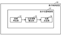
- FIG. 3 is a block diagram illustrating a configuration example of the display position control unit 40 according to the first embodiment.
- the display position control unit 40 includes a region specifying unit 41, an inclusion determination unit 42, and a superimposition region determination unit 43.
- the area specifying unit 41 specifies the first area and the second area included in the area excluding the first area in the frame in each of the plurality of frames included in the video content.
- the first region and the second region are two regions having different characteristics from each other in the frame.
- the area specifying unit 41 sets an area where the image change is larger than a predetermined size in the frame as a first area and an area where the image change is smaller than the predetermined size as a second area.
- the first area is, for example, an area (hereinafter, also referred to as “dynamic area”) in which a large image change occurs when a scene is switched.
- the second area is, for example, an area (hereinafter also referred to as a “static area”) occupied by a subject in the background or movement or change in the image.
- the present disclosure does not limit the first area and the second area to the settings described above.
- a portion where a predetermined subject is displayed in the frame may be a first region, and a portion where the predetermined subject is not displayed may be a second region.
- a method for determining the magnitude of image change will be described later.
- the plurality of frames described above are frames constituting video content received by the content receiving unit 21 from the broadcasting station 3.
- the following description will be made on the assumption that the content receiving unit 21 has already received and held the plurality of frames described above for processing in the display position control unit 40.
- the inclusion determination unit 42 determines an attention area and a non-attention area based on the positional relationship between the first area and the second area in each of the plurality of frames described above.
- the inclusion determination unit 42 sets one of the first area and the second area as the attention area and the other as the non-attention area.
- the inclusion determination unit 42 determines whether or not the first area and the second area are in a predetermined positional relationship in each of the plurality of frames described above. Specifically, the inclusion determination unit 42 determines whether one is in a positional relationship including the other. Hereinafter, such a relationship is referred to as an “inclusion relationship”.
- the “inclusion relationship” is a positional relationship in which one region surrounds the other region. In the present disclosure, the “inclusion relationship” includes not only a state in which one region surrounds the entire periphery of the other region but also a state in which one region surrounds a part of the periphery of the other region.
- the inclusion determination unit 42 is an example of an attention area estimation unit.
- a region that is included is a non-target region, and a region that is included is a target region.
- the superimposition area determination unit 43 determines a position for displaying additional information on the display screen.
- the overlapping area determination unit 43 sets a position that is commonly included in each non-attention area of each of the plurality of frames as a position for displaying additional information.
- the overlapping region determination unit 43 determines and determines one position that is commonly included in each non-attention region based on each non-attention region of the plurality of frames determined by the inclusion determination unit 42.
- the position is set as the display position of the additional information.
- This position is a position where the video output unit 14 displays additional information during a period in which the plurality of frames are displayed on the display screen.
- This position is a fixed position in the screen, that is, a position that does not move in the screen as time passes.
- the overlapping region determination unit 43 is an example of a position determination unit.
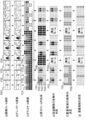
- FIGS. 11 to 13 are diagrams schematically showing specific examples of the content recognition process. Hereinafter, description will be made with reference to these drawings as appropriate.
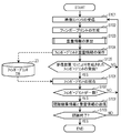
- FIG. 4 is a flowchart showing an example of content recognition processing in the first embodiment.
- the content receiving unit 21 receives video content including a plurality of frames transmitted from the broadcast station 3 (step S101).
- the fingerprint generation unit 22 generates a fingerprint for a plurality of frames of the video content received by the content reception unit 21 in step S101 (step S102).
- the display position control unit 40 calculates superimposition information (step S103).
- the display position control unit 40 displays where the additional information is displayed on the video content and in what period Is displayed.
- This additional information is additional information associated in the additional information DB 31 with the fingerprint generated in step S102 regarding the video content received in step S101.
- an area in which the additional information is displayed on the video content is also referred to as a “superimposition area”, and a display period is also referred to as a “superimposition period”.
- the fingerprint generation unit 22 stores the fingerprint generated in step S102 and the overlapping area information generated in step S103 in the fingerprint DB 23 (step S104). Thereby, the fingerprint DB 23 is updated.
- the collation unit 25 waits to receive the fingerprint generated by the receiving device 10 from the receiving device 10 (step S105).
- the fingerprint waiting for reception by the collation unit 25 is a fingerprint generated from the same video content as the video content received by the video reception unit 11 by the fingerprint generation unit 110 of the reception device 10.
- step S105 When the collation unit 25 receives the fingerprint in step S105 (Yes in step S105), the process proceeds to step S106. On the other hand, if the collation unit 25 does not receive the fingerprint in step S105 (No in step S105), the process returns to step S101, and the content reception unit 21 newly receives video content.
- the collation unit 25 collates the fingerprint received from the receiving device 10 in step S105 with the fingerprint stored in the fingerprint DB (step S106).
- the collation unit 25 determines whether or not two collated fingerprints match as a result of the collation in step S106 (step S107).
- the collation unit 25 determines whether the fingerprint generated by the fingerprint generation unit 22 in step S102 matches the fingerprint received from the receiving device 10 in step S105.
- step S107 when the collation unit 25 determines that the two fingerprints match each other (Yes in step S107), the process proceeds to step S108. On the other hand, if the collation unit 25 determines that the two fingerprints do not match each other (No in step S107), the process returns to step S101, and the content receiving unit 21 newly receives video content.
- the collation unit 25 transmits information indicating the result of collation executed in step S106 (that is, the result of image recognition) and the superimposition area information calculated in step S103 to the receiving device 10 (step S108).
- the server device 20 determines whether or not the video content has been recognized (step S109).
- the server device 20 determines whether information indicating the result of image recognition and superimposition area information have been obtained for each of a plurality of frames included in the video content. If it is determined that information indicating the result of image recognition and superimposition area information have been obtained for all frames, the content recognition process is terminated (Yes in step S109). On the other hand, when it is determined that there is a frame for which the information indicating the result of image recognition and the overlapping area information have not been obtained (No in step S109), the process returns to step S101, and the content receiving unit 21 receives the video content. Is newly received.
- step S102 and step S103 may be performed in parallel (substantially simultaneously).
- step S102 may be performed after step S103.
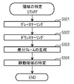
- FIG. 5 is a flowchart showing an example of the calculation process of the overlapping area information in the first embodiment.
- the series of processes shown in FIG. 5 shows details of the process in step S103 of FIG.
- the display position control unit 40 calculates a superimposed region that is a region where additional information is displayed on the video content (step S201).
- the overlapping area is determined to be a position included in an area where the degree of attention by the user is estimated to be relatively low, and a position that does not move on the screen during a period in which a plurality of frames are displayed on the display screen.
- the specific processing will be described later.
- the display position control unit 40 calculates a superposition period which is a period during which additional information is displayed on the video content (step S202).
- the superimposition period is a period in which the superimposition area is valid, and corresponds to a period in which a plurality of frames used for calculating the superimposition area are displayed on the display screen. The specific processing will be described later.
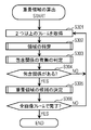
- FIG. 6 is a flowchart illustrating an example of the overlapping range calculation process according to the first embodiment.
- the flowchart shown in FIG. 6 shows details of the processing in step S201 in FIG.
- FIG. 11 is a diagram schematically showing a specific example of the content recognition process in the first embodiment.
- the display position control unit 40 acquires two or more frames among the plurality of frames received by the content receiving unit 21 (step S301).
- FIG. 11A shows an example in which nine frames are acquired, the nine frames include three different scenes, and each scene includes three frames.
- the area specifying unit 41 specifies the first area and the second area for each of the two or more frames acquired by the display position control unit 40 in step S302 (step S302).
- the region specifying unit 41 generates a difference frame by comparing two temporally adjacent frames of the two or more frames, and specifies the first region and the second region in the generated difference frame. In a processing step executed later, a position included in any one of these areas is determined as a position where the additional information is displayed.
- the difference frame is a frame indicating the magnitude of the image change in the pixel (or block including the pixel) in the frame.
- the magnitude of the change in the image is displayed in light and shade.
- the blocks having a relatively large change in the image are dark and the blocks having a relatively small change in the image are displayed light. .
- the difference frame 1141 shown in FIG. 11D will be described as a specific example.
- the difference frame 1141 is a difference frame generated from a frame 1131 and a frame 1132 generated by performing grayscale conversion and downscale conversion, which will be described later, on the image frame 1101 and the image frame 1102 illustrated in FIG. .
- a person displayed near the center of the frame is moving, there is a relatively large image change in the person area, and a relatively small image change in the peripheral part of the person. .
- a portion 1142 indicating a region including a human motion is displayed in a color relatively close to black
- a portion 1143 indicating a region having a relatively small image change is a medium dark color
- a portion 1144 that is displayed and indicates a region not included in any of the above is displayed in a color relatively close to white.
- the difference frame 1143 shown in FIG. is a difference frame generated from a frame 1134 and a frame 1134 generated by performing grayscale conversion and downscale conversion, which will be described later, on the image frame 1103 and the image frame 1104 shown in FIG. .
- the difference frame 1143 is a difference frame corresponding to scene switching. Therefore, a relatively large image change occurs between most of the pixels between the frame 1134 and the frame 1134. Therefore, almost the entire area in the difference frame 1143 is displayed in a color close to black.
- the inclusion determination unit 42 determines the positional relationship between the first area and the second area (step S303).
- the inclusion determination unit 42 determines whether or not the first region has a positional relationship including the second region. That is, the inclusion determination unit 42 determines whether or not there is an inclusion relationship between the first area and the second area.
- (E) of FIG. 11 shows an example of a frame indicating the result of determination in step S303.
- the frame shown in (e) of FIG. 11 is determined from the difference frames shown in (d) of FIG. 11 that have been included in the inclusion determination unit 42 in step S303.
- the frame indicated as “invalid frame” in FIG. 11E is determined to have no inclusion relationship in the inclusion determination unit 42 in step S303.
- the difference frame determined to have the inclusion relationship in the inclusion determination unit 42 in step S303 is used as it is for the next process.
- the difference frame determined to have no inclusion relationship in the inclusion determination unit 42 in step S303 is an invalid frame.
- a frame 1151 and a frame 1153 shown in FIG. The frame 1151 is the same frame as the difference frame 1141 shown in FIG.
- the inclusion determination unit 42 determines that there is an inclusion relationship as a result of determining whether or not there is an inclusion relationship for the difference frame 1141 shown in FIG. 11D, and therefore uses the difference frame 1141 as the frame 1151 as it is.
- the frame 1153 is an invalid frame.
- the inclusion determination unit 42 determines that there is no inclusion relationship as a result of determining the presence or absence of the inclusion relationship for the difference frame 1143 shown in FIG. As described above, the difference frame generated corresponding to the switching of the scene is likely to be an invalid frame because the change in the image is relatively large in almost the entire area of the frame.
- step S304 the process branches based on the determination result in step S303 (step S304).
- step S303 If it is determined in step S303 that the first area and the second area have an inclusion relationship (Yes in step S304), the process proceeds to step S305. On the other hand, when it is determined in step S303 that the first area and the second area have no inclusion relationship (No in step S304), the process returns to step S301, and the display position control unit 40 newly adds two or more frames. get.
- the superposition region determination unit 43 determines one of the first region and the second region as a superimposition region candidate (step S305).
- the superimposition region determination unit 43 determines a region on the side including the opponent as a superimposition region candidate in the inclusion relationship between the first region and the second region. For example, when the first area is in a positional relationship including the second area, the position included in the first area is determined as a candidate for the overlapping area.
- the superimposition area candidate means a candidate area for displaying additional information superimposed on the display screen in the video output unit 14 of the receiving device 10. Eventually, the position included in the candidate for the overlapping region is determined as the position where the additional information is displayed.
- (F) of FIG. 11 shows an example of the candidate for the overlapping area determined in step S305.
- the inclusion side region is determined as a candidate for the overlapping region.
- a frame 1161 shown in FIG. A frame 1161 indicates a candidate for the overlapping area determined by the overlapping area determination unit 43 with respect to the frame 1151 illustrated in FIG.
- a portion 1162 of the frame 1161 is a candidate for an overlapping region in the frame 1161.
- the portion 1162 is a portion corresponding to the region including the opponent among the first region and the second region set in the frame 1151.
- step S305 If the process of step S305 has been executed previously, the superimposition area determination unit 43 has been determined in step S305 this time in a state where the candidate for the superimposition area determined in the previous step S305 is held. A new overlap region candidate is obtained. In that case, the position included in the candidate for the overlapping region newly obtained in step S305 is added to the candidate for the overlapping region held as a result of the previous step S305.
- the display position control unit 40 determines whether or not the processing from step S302 to step S305 has been performed on all of the plurality of frames received by the content receiving unit 21 (step S306).
- step S306 If it is determined in step S306 that the processing from step S302 to step S305 has been performed on all frames (Yes in step S306), the series of processing illustrated in FIG. 6 ends. On the other hand, when it is determined in step S306 that there is a frame that has not been processed yet (No in step S306), the process returns to step S301, and the display position control unit 40 newly adds two or more frames. To get to.
- FIG. 7 is a flowchart illustrating an example of the superimposition period calculation process in the first embodiment.
- the flowchart shown in FIG. 7 shows details of the process in step S202 of FIG.
- the overlapping area determination unit 43 calculates an area that is commonly included in two or more overlapping area candidates determined in step S305 in FIG. 6 (hereinafter, referred to as “common area”) as the overlapping area. And the superposition area information which is the information which shows a superposition area is held. In addition, the overlapping area determination unit 43 calculates a period during which a frame including a candidate for the overlapping area is displayed on the display screen as the overlapping period. Then, superimposition period information which is information indicating the superposition period is held (step S401).
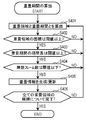
- the overlapping area determination unit 43 determines whether or not the area of the overlapping area calculated in step S401 is equal to or larger than a predetermined threshold (hereinafter also referred to as “superimposing area threshold”) (step S402).
- step S402 it is determined whether or not the overlapping area calculated in step S401 has a sufficient size for displaying additional information.
- step S402 If it is determined in step S402 that the area of the overlapping region is equal to or larger than the overlapping area threshold (Yes in step S402), the process proceeds to step S403. On the other hand, when it is determined that the area of the overlapping area is less than the overlapping area threshold (No in step S402), the process returns to step S401 to newly calculate the overlapping area.
- the superposition region determination unit 43 determines whether or not the time length of the superposition period calculated in step S401 is equal to or greater than a predetermined threshold (hereinafter also referred to as “superimposition time threshold”) (step S403).
- step S403 it is determined whether or not the overlapping period calculated in step S401 is displayed at the same position for a period sufficient for the user to visually recognize the additional information.
- the superimposition time threshold is, for example, about 5 to 10 seconds, but the present disclosure is not limited to this value.
- the superimposition time threshold value may be set so that the above-mentioned fixed period becomes longer, or the superposition time threshold value may be set so as to be shorter.
- Step S403 when it is determined that the time length of the superposition period is equal to or greater than the superposition time threshold (Yes in Step S403), the process proceeds to Step S404. On the other hand, when it is determined that the length of the superimposition period is less than the superimposition time threshold (No in step S403), the process returns to step S401, and a new superimposition area is calculated.
- the superimposition area determination unit 43 determines whether or not the number of invalid frames included in the superposition period calculated in step S401 is equal to or less than a predetermined threshold (hereinafter also referred to as “invalid frame threshold”) (step S404). .
- step S404 it is determined whether or not the number of invalid frames included in the superposition period calculated in step S401 is appropriate.
- step S404 it may be determined whether the number of non-invalid frames is a predetermined number or more without determining whether the number of invalid frames is equal to or less than the invalid frame threshold.
- step S404 If it is determined in step S404 that the number of invalid frames is equal to or less than the invalid frame threshold (Yes in step S404), the process proceeds to step S405. On the other hand, when it is determined that the number of invalid frames exceeds the invalid frame threshold (No in step S404), the process returns to step S401, and a new overlapping area is calculated.
- the superimposition area determination unit 43 generates superimposition information based on the superimposition area information and the superimposition period information. Then, the generated superposition information is held (step S405).
- the superimposition area determination unit 43 includes superimposition area information, which is information indicating the superimposition area, for the superimposition area determined to be appropriate for displaying additional information in any of steps S402, S403, and S404.
- region determination part 43 adds superimposition information newly produced
- FIG. 11 shows an example of the overlapping area indicated by the overlapping information generated in step S405. As shown in (g) of FIG. 11, a position that is commonly included in the candidates for the respective overlapping regions shown in (f) of FIG. 11 is determined as the overlapping region.
- the overlapping area determination unit 43 determines whether or not the processing from step S401 to step S405 has been performed on all of the two or more overlapping area candidates (step S406).
- step S406 when it is determined that the processing from step S401 to step S405 has been performed on all the candidates for the overlapping region (Yes in step S406), the series of processing illustrated in FIG. 7 ends. On the other hand, if it is determined in step S406 that there is a candidate for an overlap area that has not yet been processed from step S401 to step S405 (No in step S406), the process returns to step S401, and the overlap area is newly set. calculate.
- FIG. 8 is a flowchart showing an example of the area specifying process in the first embodiment.
- the flowchart shown in FIG. 8 shows details of the processing in step S302 of FIG.
- the area specifying unit 41 performs gray scaling processing (step S501).
- the gray scaling process is to convert a color image into a gray scale image, that is, to perform gray scale conversion.
- the region specifying unit 41 converts the color image into a grayscale image by executing gray scaling processing and converting the color information of each pixel of the frame into a luminance value.
- the present disclosure does not limit this conversion technique.
- the region specifying unit 41 may extract one of RGB of the pixel and convert it into a luminance value.
- the luminance value may be calculated for each pixel.
- an example of performing gray scaling processing for calculating a luminance value for each pixel will be described.
- the area specifying unit 41 that is the main body that executes Step S501 is one of the functional blocks of the display position control unit 40 as illustrated in FIG.
- the region specifying unit 41 is one of functional blocks included in the fingerprint generating unit 22.
- FIG. 11B shows an example of a frame obtained as a result of the gray scaling process in step S501.
- the frame shown in (b) of FIG. 11 is obtained by performing gray scaling processing on each of the frames shown in (a) of FIG.
- step S502 the area specifying unit 41 performs a downscaling process.
- the downscaling process is to convert the number of pixels constituting one frame from the original number of pixels to a smaller number of pixels, that is, to perform downscale conversion.
- the area specifying unit 41 performs a downscaling process and converts the image of the frame into an image configured with a smaller number of pixels.
- the present disclosure does not limit this conversion technique.
- the area specifying unit 41 divides the frame into a plurality of blocks so that a plurality of pixels included in the frame are included in one block, and calculates one luminance value for each block, thereby performing the downscale conversion. You may go.
- the area specifying unit 41 may calculate, for each block, an average value or an intermediate value of the luminance values of the pixels included in the block to obtain the luminance value of the block.
- FIG. 11C shows an example of a frame obtained as a result of the downscaling process in step S502.
- the frame shown in (c) of FIG. 11 is obtained by performing downscaling processing on each of the frames shown in (b) of FIG.
- the area specifying unit 41 generates a difference frame (step S503).
- the difference frame is generated by calculating a difference in luminance value between two temporally adjacent frames (for example, two temporally continuous frames).
- the area specifying unit 41 generates a difference frame by calculating a difference in luminance value between blocks at the same position for each block of two temporally adjacent frames. Note that the difference (absolute value) of luminance values calculated for each block is referred to as a “difference value”.
- FIG. 11D shows an example of the difference frame generated in step S503.
- the magnitude of the change in the image is displayed in light and shade.
- the block having a relatively large change in the image is dark and the block having a relatively small change in the image is displayed light. Yes.
- the area specifying unit 41 specifies a static area (step S504).
- the specification of the static area is a process for specifying the dynamic area and the static area in the frame.
- the area specifying unit 41 sets a block in which the difference value of the block in the difference frame generated in step S503 is larger than a predetermined value as a dynamic block, and sets a block whose difference value is smaller than a predetermined value as a static block.
- region specific part 41 specifies a dynamic area
- the predetermined value is preferably set appropriately based on the maximum value that can be taken by the difference value so that the dynamic area and the static area can be appropriately set.
- each processing of step S501 to step S503 is also processing executed by the fingerprint generation unit 22 as part of processing for generating a fingerprint. Therefore, the region specifying unit 41 does not perform steps S501 to S503, but acquires the difference frame generated by the same processing as the steps S501 to S503 performed by the fingerprint generation unit 22 from the fingerprint generation unit 22. May be.
- FIG. 9 is a flowchart illustrating an example of a process for determining whether or not there is an inclusion relationship in the first embodiment.
- the flowchart shown in FIG. 9 shows details of the processing in step S303 in FIG.
- FIG. 12 is a first diagram schematically showing a specific example of the superimposition display availability determination process in the first embodiment.
- FIG. 13 is a second diagram schematically illustrating a specific example of the superimposition display availability determination process according to the first embodiment.
- the inclusion determination unit 42 calculates the static area ratio (step S601).
- the inclusion determination unit 42 calculates the ratio between the static area and the dynamic area specified in step S504. Note that the inclusion determination unit 42, which is the subject that executes Step S601, is one of the functional blocks of the display position control unit 40, as shown in FIG. In addition, referring to FIG. 1, it can be said that the inclusion determination unit 42 is one of the functional blocks included in the fingerprint generation unit 22.
- FIG. 12A shows an example of a difference frame to be processed.
- FIG. 12B shows an example of the number of blocks in the static area and the dynamic area in the difference frame shown in FIG.
- the difference frame has a static area of 16 blocks and a dynamic area of 2 blocks.
- the ratio between the static area and the dynamic area is 89%: 11%.
- the inclusion determination unit 42 generates a height histogram and a width histogram of the region (step S602).
- the height histogram and the width histogram are information indicating which position the static region or the dynamic region occupies in each direction of height and width in the difference frame.
- the inclusion determination unit 42 generates a height histogram and a width histogram for a region having a smaller ratio calculated in step S601 (a dynamic region in the example illustrated in FIG. 12).
- the downward direction is the height direction
- the numerical value increases as it goes downward.
- the leftmost column in the frame is the origin
- the right direction is the width direction
- the numerical value increases toward the right.
- the height direction and the width direction described above are merely examples, and the present disclosure is not limited to this definition.
- the height direction and the width direction may be determined by a definition different from the above, and even in such a case, it is possible to perform the same processing as the above definition.
- step S602 will be specifically described with reference to FIG. FIG. 12C schematically shows a specific example of a histogram calculation method.
- the inclusion determination unit 42 selects a smaller one of the blocks included in each region (that is, a smaller region area) out of the static region and the dynamic region in the difference frame to be processed.
- the target of histogram calculation In the example shown in FIG. 12, the dynamic region is a target for calculating the histogram.
- the inclusion determination unit 42 calculates a height histogram for the calculation target region.
- the height histogram is represented by an array of numerical values equal to the number of blocks in the height direction in the difference frame, and each numerical value (hereinafter also referred to as “frequency”) represents the number of blocks in the width direction of the calculation target area. To do.
- the number of blocks in the height direction and the width direction of the difference frame is 5, respectively. Therefore, the height histogram is represented as information in which any one of the numerical values from 0 to 5 is arranged.
- the inclusion determination unit 42 calculates a width histogram for the calculation target region.
- the width histogram is represented by an array of numerical values equal to the number of blocks in the width direction in the difference frame, and each numerical value (hereinafter also referred to as “frequency”) is the number of blocks in the height direction of the calculation target region. .
- frequency each numerical value
- the width histogram is expressed as information in which any one of 0 to 5 is arranged.
- the width histogram is “0, 0, 2, 0, 0”.
- the inclusion determination unit 42 calculates the degree of dispersion of the region (step S603).
- the inclusion determination unit 42 calculates the degree of dispersion of the region in the difference frame using the height histogram and the width histogram generated in step S602.
- step S603 will be specifically described with reference to FIG.
- FIG. 12D shows a specific example of a method for calculating the degree of dispersion.
- the degree of dispersion is calculated as the mean square of the difference between each frequency in the histogram and the average frequency.
- the average value of the frequency is 0.4 for both the height histogram and the width histogram. Therefore, as shown in FIG. 12D, regarding the difference frame to be processed, the variance in the height direction of the dynamic region is 0.24, and the variance in the width direction is 0.64.
- the inclusion determination unit 42 generates a center weight vector (step S604).
- the center weight vector is an index indicating the distance from the center to each block in the frame. Each element of the center weight vector corresponds to one block. Each element of the center weight vector is a numerical value of 0 or more and 1 or less, becomes 1 at the center, and approaches 0 as the distance from the center increases. In this way, the center weight vector is determined. In the example illustrated in FIG. 12, the center weight vector is, for example, “0.1, 0.5, 1, 0.5, 0.1”.
- the center weight vector having five elements is represented in the height direction and the width direction.
- Each can be used in common.
- different center weight vectors may be used in the height direction and the width direction.
- the inclusion determination unit 42 generates a centroid vector (step S605).
- the centroid vector is an index indicating the distance from each centroid in the height direction and the width direction to each block.
- Each element of the centroid vector is a numerical value from 0 to 1, and becomes 1 at the position of the centroid (or a position closest to the centroid), and approaches 0 as the distance from the centroid increases. In this way, the center of gravity vector is determined.
- each element of the centroid weight vector The greater the value of each element of the centroid weight vector, the higher the tendency that the block is determined to be closer to the centroid. That is, if the numerical value of each element is large in a wide range including the centroid in the centroid vector, a wide area including the centroid is easily recognized as the centroid. On the other hand, if the numerical value is large only for a narrow range element including the centroid in the centroid vector, a narrow area including the centroid is easily recognized as the centroid of the frame.
- the center-of-gravity vector is calculated based on the height histogram in the height direction and based on the width histogram in the width direction.
- FIG. 13 (f) shows a specific example of obtaining the height direction centroid vector and the width direction centroid vector from the height histogram and the width histogram shown in FIG. 12 (c).
- the element at the position of the coordinate “2” in the height direction is 1, and each element is determined according to the distance from the center of gravity so as to approach 0 as the distance from the center of gravity increases. In this way, the center-of-gravity vector “0.5, 1, 0.5, 0.33, 0.25” in the height direction is generated.
- Each element of the width histogram (“0, 0, 2, 0, 0” in the examples shown in FIGS. 12 and 13) and the coordinate in the width direction (“1, 2, 3, 4, 5 ”) are calculated for all elements of the width histogram and added together. Then, the value obtained by dividing the sum by the number of blocks in the calculation target area (in the example shown in FIG. 13, the number of blocks in the moving enemy area) plus 1 is used as the barycentric position. In the example shown in FIG. 13, since a numerical value of 2 is obtained, the position of the coordinate “2” in the width direction is the position of the center of gravity.
- the centroid vector in the width direction the element at the position of the coordinate “2” in the width direction is 1, and each element is determined according to the distance from the centroid so as to approach 0 as the distance from the centroid. In this way, the centroid vectors “0.5, 1, 0.5, 0.33, 0.25” in the width direction are generated.
- the reason why 1 is added to the denominator in the calculation formula shown in FIG. 13F is to avoid division by zero.
- the denominator may be the number of blocks of the difference frame to be processed (25 in the example shown in FIG. 12).
- the inclusion determination unit 42 calculates an inclusion degree (step S606).
- the inclusion level is an index indicating the degree to which one of the static region and the dynamic region includes the other.
- the inclusion determination unit 42 determines that one of the static region and the dynamic region includes the other when the inclusion degree is greater than a predetermined threshold. Note that it is impossible to know which side is the inclusion side and which is the inclusion side by the inclusion degree alone.
- the degree of inclusion is calculated from the height histogram and width histogram calculated in step 602, the center weight vector generated in step S604, and the center vector in the height direction and the center vector in the width direction generated in step S605.
- FIG. 1 A specific example of calculating the inclusion level is shown in FIG. 1
- the inclusion level is calculated for each block by calculating the product of the histogram, the center weight vector, and the centroid weight vector for each block in the height direction and the width direction. Calculated by calculating the average of the elements.
- the inclusion vector in the height direction is “0, 0.5, 0.5, 0, 0”
- the inclusion vector in the width direction is “0, 0, 1, 0, 0”. It becomes. Accordingly, the degree of inclusion is 0.67.
- the inclusion determination unit 42 outputs the inclusion information (step S607).
- the inclusion information is information indicating whether or not a frame to be processed has an inclusion relationship.
- the inclusion level calculated in step S606 is greater than a predetermined threshold (hereinafter also referred to as “inclusion level threshold”), the inclusion determination unit 42 outputs information indicating that there is an inclusion relationship as inclusion information. If the inclusion level threshold is 0.5, for example, in the example shown in FIG. 13, the inclusion level is 0.67, so inclusion information indicating that there is an inclusion relationship is output from the inclusion determination unit 42.
- the inclusion determination unit 42 outputs information indicating that there is no inclusion relationship as inclusion information. When both are equal, there may be an inclusion relationship or no inclusion relationship.
- the numerical values given as threshold values in the present embodiment are merely examples. Each threshold is preferably set appropriately according to the specifications of the server device 20 and the like.
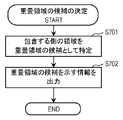
- FIG. 10 is a flowchart illustrating an example of a process for determining a candidate for an overlapping area according to the first embodiment.
- the flowchart shown in FIG. 10 shows details of the processing in step S305 in FIG.
- the overlapping area determination unit 43 specifies the including area as a candidate for the overlapping area (step S701).
- the superimposition region determination unit 43 acquires the inclusion information output in step S607 and determines whether or not there is an inclusion relationship. When there is an inclusion relationship, the overlapping area determination unit 43 sets an area having a larger number of blocks among the static area and the dynamic area as an inclusion area.
- region determination part 43 which is a main body which performs step S701 is one of the functional blocks which the display position control part 40 has, as shown in FIG. Also, referring to FIG. 1, it can be said that the overlapping region determination unit 43 is one of functional blocks included in the fingerprint generation unit 22.
- the overlapping area determination unit 43 outputs information indicating a candidate for the overlapping area (step S702).
- the information indicating the candidate for the overlapping area is information indicating the candidate for the overlapping area specified in step S701, and indicates the position of the candidate for the overlapping area in the frame and the display time in the video content. Information.
- the display position control unit 40 identifies an area that is estimated to have a relatively low level of attention by the user in each of the plurality of frames, and determines the position included in the identified area for a predetermined time.
- the position for displaying additional information is determined.
- the additional information is superimposed on a non-attention area where the degree of attention is estimated to be low on the display screen, so that when the user views the video content, the additional information is prevented from becoming an obstacle to viewing. Can do.
- FIG. 14A is a diagram schematically illustrating an example of the position of the overlapping region in the first embodiment.
- FIG. 14B is a diagram schematically illustrating another example of the position of the overlapping region in the first embodiment.
- the display position of the additional information determined by the display position control unit 40 in the present embodiment will be described with reference to FIGS. 14A and 14B.
- a static region 1401 exists in the central portion, and a dynamic region 1402 exists in a peripheral portion excluding the central portion in the frame.
- the display position control unit 40 makes the static area 1401 a relatively high attention area (attention area) and relatively focuses on the dynamic area 1402 by the series of processes described above. It is assumed that the area is low (non-attention area).
- the position included in the dynamic area 1402 is set as a position for displaying the additional information 1403. As a result, when the frame is displayed on the display screen, additional information 1403 is displayed at a position included in the dynamic area 1402.
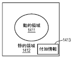
- a dynamic region 1411 exists in the central portion, and a static region 1412 exists in a peripheral portion excluding the central portion in the frame.
- the display position control unit 40 estimates the dynamic area 1411 as a relatively high attention area (attention area) by the series of processes described above, and sets the static area 1412 as a relative area. It is estimated that the region has a low attention level (non-attention region).
- the position included in the static area 1412 is set as a position for displaying the additional information 1413. As a result, when the frame is displayed on the display screen, additional information 1413 is displayed at a position included in the static area 1412.
- the server device 20 identifies a non-attention area that is estimated to have a relatively low level of attention by the user in each of a plurality of frames.
- a position that is commonly included in each non-attention area of a plurality of frames is set as a position for displaying additional information.
- the additional information is superimposed on a position excluding the attention area that is estimated to have a high degree of attention on the display screen, so that when the user views the video content, the additional information is prevented from being an obstacle to viewing. can do.
- one server device 20 provides image recognition processing to hundreds to thousands of receiving devices 10. According to the present embodiment, by performing the calculation process of the display position of the additional information in the server device 20, it is not necessary to perform the process of calculating the display position of the additional information in each of the reception devices 10. The amount of processing can be reduced.
- a recording medium such as a system, an apparatus, an integrated circuit, a computer program, or a computer-readable CD-ROM.
- the system, the apparatus, the integrated circuit, and the computer program And any combination of recording media.
- Embodiment 2 will be described with reference to FIGS.
- FIG. 15 is a block diagram illustrating a configuration example of the content recognition system 1A according to the second embodiment.
- FIG. 16 is a block diagram illustrating a configuration example of the receiving device 10A according to the second embodiment.
- FIG. 16 shows the main hardware configuration of the receiving apparatus 10A.
- the content recognition system 1A includes a broadcasting station 3, an STB (Set Top Box) 4, a receiving device 10A, a server device 20A, and an additional information server device 30.
- the receiving device 10A is an example of a display control device.
- constituent elements that operate substantially the same as the constituent elements described in the first embodiment are given the same reference numerals as those given in the first embodiment, and redundant description is omitted. In the present embodiment, differences from the first embodiment will be described.
- the receiving device 10A includes an image recognition unit 100A, a video reception unit 11, a video extraction unit 12, an additional information acquisition unit 13, a video output unit 14, a control unit 15, an operation signal reception unit 16, and an HTTP transmission / reception. Unit 17.
- the image recognition unit 100A includes a fingerprint generation unit 110A, a fingerprint acquisition unit 120, a collation unit 130, and an output unit 140.
- the fingerprint generation unit 110A performs substantially the same operation as the fingerprint generation unit 110 described in the first embodiment.
- the fingerprint generation unit 110 ⁇ / b> A generates a fingerprint based on the video content received by the video reception unit 11.
- the fingerprint generation unit 110 ⁇ / b> A includes a display position control unit 45.
- the display position control unit 45 performs substantially the same operation as the display position control unit 40 included in the server device 20 described in the first embodiment.
- the display position control unit 45 is a control circuit that controls a position where additional information is displayed when the video output unit 14 displays received video content on the display screen.
- Fingerprint acquisition unit 120 acquires a fingerprint from fingerprint DB 23 of server device 20A.
- the fingerprints acquired by the fingerprint acquisition unit 120 include a predetermined number of fingerprints stored in the fingerprint DB 23 including video content broadcast from the broadcast station 3 when the image recognition unit 100A performs image recognition processing. Is a fingerprint of the video content.
- the collation unit 130 performs substantially the same operation as the collation unit 25 included in the server device 20 described in the first embodiment.
- the collation unit 130 collates the fingerprint generated by the fingerprint generation unit 110A with the fingerprint acquired by the fingerprint acquisition unit 120 from the server device 20A.
- the server device 20A includes a content reception unit 21, a fingerprint generation unit 22A, and a fingerprint DB 23.
- the fingerprint generation unit 22A generates a fingerprint for each video content based on the received video content.
- the fingerprint generator 22A does not include a display position controller. In this respect, the fingerprint generation unit 22A is different from the fingerprint generation unit 22 in the first embodiment.
- FIG. 17 is a flowchart illustrating an example of content recognition processing according to the first embodiment.
- the video receiver 11 receives video content including a plurality of frames transmitted from the broadcast station 3 (step S801).
- the fingerprint generation unit 110A generates a fingerprint for a plurality of frames of the video content received by the video reception unit 11 in step S801 (step S802).
- the display position control unit 45 calculates superimposition information (step S803).
- the display position control unit 45 displays where the additional information is displayed on the video content and in what period Is displayed.
- This additional information is additional information associated in the additional information DB 31 with the fingerprint generated in step S802 regarding the video content received in step S801. Note that an area where the additional information is displayed on the video content is a “superimposition area”, and a period during which the additional information is displayed is a “superimposition period”.
- the fingerprint generation unit 110A holds the fingerprint generated in step S802 and the overlapping area information generated in step S803 in a storage device (not shown) included in the reception device 10A (step S804).
- the fingerprint acquisition unit 120 waits to receive the fingerprint generated by the server device 20A from the server device 20A (step S805).
- the fingerprint awaiting reception by the fingerprint acquisition unit 120 is a fingerprint generated from the same video content as the video content received by the video reception unit 11 by the fingerprint generation unit 22A of the server device 20A.
- step S805 When the fingerprint acquisition unit 120 receives the fingerprint in step S805 (Yes in step S805), the process proceeds to step S806. On the other hand, if the fingerprint acquisition unit 120 does not receive a fingerprint in step S805 (No in step S805), the process returns to step S801, and the video reception unit 11 newly receives video content.
- the collation unit 130 collates the fingerprint generated by the fingerprint generation unit 110A in step S802 with the fingerprint received from the server device 20A in step S805 (step S806).
- the collation unit 130 determines whether or not two collated fingerprints match as a result of the collation in Step S806 (Step S807).
- the collation unit 130 determines whether or not the fingerprint generated by the fingerprint generation unit 110A in step S802 matches the fingerprint received from the server device 20A in step S805.
- step S807 when the collation unit 130 determines that the two fingerprints match each other (Yes in step S807), the process proceeds to step S808. On the other hand, if the collation unit 130 determines that the two fingerprints do not match each other (No in step S807), the process returns to step S801, and the video reception unit 11 newly receives video content.
- the image recognition unit 100A determines whether or not the video content has been recognized (step S808).
- the image recognition unit 100A determines whether information indicating the result of image recognition and superimposition area information have been obtained for each of a plurality of frames included in the video content. If it is determined that information indicating the result of image recognition and superimposition area information have been obtained for all frames, the content recognition process ends (Yes in step S808). On the other hand, if it is determined that there is a frame for which the information indicating the result of image recognition and the superimposition area information have not yet been obtained (No in step S808), the process returns to step S801, and the video receiving unit 11 Is newly received.
- receiving apparatus 10A in the present embodiment specifies a non-attention area in which a degree of attention by the user is estimated to be relatively low in each of a plurality of frames.
- a position that is commonly included in each non-attention area of a plurality of frames is set as a position for displaying additional information.
- the additional information is superimposed on a position excluding the attention area that is estimated to have a high degree of attention on the display screen, so that when the user views the video content, the additional information is prevented from being an obstacle to viewing. can do.
- the receiving device 10A performs the calculation process of the display position of the additional information. Therefore, processing suitable for the configuration and installation environment of the receiving apparatus 10A can be performed.
- the display control device is a device for displaying additional information associated with video content using a fingerprint together with the video content on the display screen.
- the display control device includes an area specifying unit, an attention area estimating unit, and a position determining unit.
- the area specifying unit specifies a first area and a second area included in an area excluding the first area in the frame in each of the plurality of frames included in the video content.
- the attention area estimation unit sets one of the first area and the second area as the attention area and the other as the non-area based on the positional relationship between the first area and the second area in each of the plurality of frames.
- the region of interest sets a position that is commonly included in each non-attention area of the plurality of frames as a position for displaying additional information.
- each of the server device 20 and the receiving device 10A is an example of a display control device.
- Each of the region specifying unit 41, the region specifying unit 52, and the display position control unit 45 is an example of a region specifying unit.
- the inclusion determination unit 42, the attention area estimation section 53, and the display position control section 45 are examples of the attention area estimation section.
- Each of the overlapping area determination unit 43, the position determination unit 54, and the display position control unit 45 is an example of a position determination unit.
- the dynamic area is an example of the first area
- the static area is an example of the second area.
- the included region is an example of an attention region
- the inclusion region is an example of a non-attention region.
- Each of the static area 1401 and the dynamic area 1411 is an example of an attention area
- each of the dynamic area 1402 and the static area 1412 is an example of a non-attention area.
- the display control device shown in the present disclosure it is possible to display additional information in an area where the degree of attention by the user is estimated to be relatively low in each of a plurality of frames.
- the additional information is superimposed on a position excluding the attention area that is estimated to have a high degree of attention on the display screen, so that when the user views the video content, the additional information is prevented from being an obstacle to viewing. can do.
- a position that is commonly included in each non-attention area of a plurality of frames is set as a position for displaying additional information. Therefore, it is possible to prevent the additional information from frequently moving in the display screen, and it is possible to avoid the additional information from being an obstacle to viewing when the user views the video content.
- the attention area estimation unit determines which one of the plurality of frames is to be included when any one of the first area and the second area includes the other.
- the region of interest may be the region of interest.
- the display control apparatus estimates that the user is paying attention to the second area. That is, the display control apparatus estimates that the first area is an area where the degree of attention by the user is relatively low, and determines a position where additional information is displayed in the first area. As a result, the display control apparatus can accurately estimate the attention area and the non-attention area, and can display additional information at a more appropriate position on the video content.
- the position determination unit In the display control device, the position determination unit generates information indicating a position where the additional information is displayed when a period in which the plurality of frames on which the additional information is superimposed is displayed on the display screen is equal to or longer than a predetermined time. May be.
- the display control device can determine that the additional information is not displayed when the period during which the plurality of frames to be superimposed with the additional information are displayed on the display screen is short. Thereby, it is possible to prevent the additional information that is short in display period and difficult to be visually recognized by the user from being displayed on the display screen.
- the position determination unit may generate information indicating a position where the additional information is displayed when a region of the position where the additional information is displayed is a predetermined area or more.
- the display control apparatus can determine that the additional information is displayed on the display screen only when a region for superimposing the additional information is secured. Therefore, it is possible to prevent the additional information from being displayed overlapping the attention area.
- the region specifying unit detects a change in the image between two temporally adjacent frames, and sets a region in which the change in the image is greater than a predetermined value as a dynamic region, and the change in the image is in the predetermined range.
- a region smaller than the value may be a static region, one of the static region and the dynamic region may be a first region, and the other may be a second region.
- the display control method is a display control method for displaying additional information associated with video content using a fingerprint together with the video content on the display screen.
- this display control method in each of a plurality of frames included in video content, a first region and a second region included in a region other than the first region in the frame are specified, and each of the plurality of frames , Based on the positional relationship between the first area and the second area, one of the first area and the second area is set as the attention area and the other is set as the non-attention area, and each of the plurality of frames A position commonly included in the non-attention area is set as a position for displaying additional information.
- Embodiments 1 and 2 have been described as examples of the technology disclosed in the present application. However, the technology in the present disclosure is not limited to this, and can also be applied to embodiments in which changes, replacements, additions, omissions, and the like are performed. Moreover, it is also possible to combine each component demonstrated in the said Embodiment 1, 2 and it can also be set as a new embodiment.
- FIG. 18 is a block diagram illustrating a modification of the configuration of the display control device 50 according to the embodiment.
- the display control device 50 includes a display position control unit 51.
- the display position control unit 51 includes a region specifying unit 52, a region of interest estimation unit 53, and a position determination unit 54.
- the area specifying unit 52 specifies the first area and the second area included in the area excluding the first area in the frame in each of the plurality of frames included in the video content.
- the attention area estimation unit 53 determines one of the first area and the second area as the attention area based on the positional relationship between the first area and the second area in each of the plurality of frames. The other is determined as a non-attention area.
- the position determination unit 54 determines a position that is commonly included in the non-attention area in each of the plurality of frames as a position for displaying additional information.
- the display control device 50 can superimpose the additional information at a more appropriate position on the video content and display the video content on which the additional information is superimposed on the display screen.
- the server device 20 recognizes the video content substantially in real time is shown, but the present disclosure is not limited to this operation example.
- the server device 20 when the receiving device 10 reads and displays video content (for example, recorded program content) stored in a recording medium, the server device 20 operates in the same manner as in the first embodiment described above, Video content can be recognized.
- the server device 20 shown in the first embodiment can be used for recognition of advertising content, for example. Alternatively, it can be used for recognizing program content such as dramas and variety.
- the receiving device 10 receives from the additional information server device 30 as additional information based on the result of image recognition, for example, the performer's own profile, the clothes worn by the performer, the place where the performer visited, etc.
- the acquired information may be acquired and superimposed on the displayed video.
- the server device 20 may receive not only advertising content but also video content such as program content, and generate a fingerprint corresponding to the video content.
- the fingerprint DB 23 may hold not only the advertising content but also a fingerprint corresponding to the program content in association with the content ID.
- the present disclosure may be realized not only as a device but also as a method in which processing means constituting the device is used as a step. Moreover, you may implement
- each processing may be realized by centralized processing by a single device (system), or may be realized by distributed processing by a plurality of devices. Also good.
- the present disclosure can be applied to a display control apparatus that displays additional information at a more appropriate position on the video content.
- the present disclosure can be applied to a video receiving device such as a television or a server device.
Abstract
Description
以下、図1~14を用いて、実施の形態1を説明する。 (Embodiment 1)
The first embodiment will be described below with reference to FIGS.
まず、本実施の形態におけるコンテンツ認識システム1について、図1を用いて説明する。 [1-1. Content recognition system]
First, the
まず、本実施の形態における受信装置10について、図1を参照しながら図2を用いて説明する。 [1-2. Receiver]
First, the receiving
次に、本実施の形態におけるサーバ装置20について、図1、図2を用いて説明する。 [1-3. Server device]
Next, the
次に、付加情報サーバ装置30について説明する。 [1-4. Additional information server device]
Next, the additional
次に、本実施の形態における表示位置制御部40について説明する。なお、図1に示すように、表示位置制御部40は、フィンガープリント生成部22が有する機能ブロックの1つである。 [1-5. Display position control unit]
Next, the display
以上のように構成された表示位置制御部40について、その動作を説明する。なお、図4~図10はコンテンツ認識処理に含まれる処理のフローチャートであり、図11~図13はコンテンツ認識処理の具体例を模式的に示す図である。以下では、これらの図を適宜参照しながら、説明を行う。 [1-6. Operation]
The operation of the display
以上のように、本実施の形態におけるサーバ装置20は、複数のフレームのそれぞれにおいて、ユーザによる注目度が相対的に低いと推定される非注目領域を特定する。そして、複数のフレームの各非注目領域に共通に含まれる位置を、付加情報を表示する位置とする。 [1-7. Effect]
As described above, the
実施の形態1では、サーバ装置20で画像認識を行う構成例を説明した。実施の形態2では、受信装置10Aで画像認識を行う構成例を説明する。 (Embodiment 2)
In the first embodiment, the configuration example in which the
まず、本実施の形態におけるコンテンツ認識システム1Aについて、図15、図16を用いて説明する。 [2-1. Constitution]
First, the content recognition system 1A in the present embodiment will be described with reference to FIGS.
図17は、実施の形態1におけるコンテンツ認識処理の一例を示すフローチャートである。 [2-2. Operation]
FIG. 17 is a flowchart illustrating an example of content recognition processing according to the first embodiment.
以上のように、本実施の形態における受信装置10Aは、複数のフレームのそれぞれにおいて、ユーザによる注目度が相対的に低いと推定される非注目領域を特定する。そして、複数のフレームの各非注目領域に共通に含まれる位置を、付加情報を表示する位置とする。 [2-3. Effect]
As described above, receiving
以上のように、本開示における表示制御装置は、フィンガープリントを用いて映像コンテンツに対応付けられる付加情報を、映像コンテンツと共に表示画面に表示するための装置である。この表示制御装置は、領域特定部と、注目領域推定部と、位置決定部と、を備える。領域特定部は、映像コンテンツに含まれる複数のフレームのそれぞれにおいて、第一領域と、当該フレーム内の第一領域を除く領域に含まれる第二領域と、を特定する。注目領域推定部は、複数のフレームのそれぞれにおいて、第一領域と第二領域との位置関係に基づいて、第一領域と第二領域とのうち、いずれか一方を注目領域とし、他方を非注目領域とする。位置決定部は、複数のフレームのそれぞれの非注目領域に共通に含まれる位置を、付加情報を表示する位置とする。 [3. Summary]
As described above, the display control device according to the present disclosure is a device for displaying additional information associated with video content using a fingerprint together with the video content on the display screen. The display control device includes an area specifying unit, an attention area estimating unit, and a position determining unit. The area specifying unit specifies a first area and a second area included in an area excluding the first area in the frame in each of the plurality of frames included in the video content. The attention area estimation unit sets one of the first area and the second area as the attention area and the other as the non-area based on the positional relationship between the first area and the second area in each of the plurality of frames. The region of interest. The position determining unit sets a position that is commonly included in each non-attention area of the plurality of frames as a position for displaying additional information.
以上のように、本出願において開示する技術の例示として、実施の形態1、2を説明した。しかしながら、本開示における技術は、これに限定されず、変更、置き換え、付加、省略等を行った実施の形態にも適用できる。また、上記実施の形態1、2で説明した各構成要素を組み合わせて、新たな実施の形態とすることも可能である。 (Other embodiments)
As described above,
3 放送局
4 STB
10,10A 受信装置
11 映像受信部
11a 映像入力部
11b 第1外部入力部
11c 第2外部入力部
12 映像抽出部
13 付加情報取得部
14 映像出力部
15 制御部
16 操作信号受信部
17 HTTP送受信部
18 付加情報格納部
19 付加情報表示制御部
20,20A サーバ装置
21 コンテンツ受信部
22,22A,110,110A フィンガープリント生成部
23 フィンガープリントDB
24 表示位置情報
25,130 照合部
30 付加情報サーバ装置
31 付加情報DB
40,45,51 表示位置制御部
41,52 領域特定部
42 包含判定部
43 重畳領域決定部
50 表示制御装置
53 注目領域推定部
54 位置決定部
100,100A 画像認識部
120 フィンガープリント取得部
140 出力部
1401,1412 静的領域
1402,1411 動的領域
1403,1413 付加情報 1,1A
10,
24
40, 45, 51 Display
Claims (7)
- フィンガープリントを用いて映像コンテンツに対応付けられる付加情報を、前記映像コンテンツと共に表示画面に表示するための表示制御装置であって、
前記映像コンテンツに含まれる複数のフレームのそれぞれにおいて、第一領域と、当該フレーム内の前記第一領域を除く領域に含まれる第二領域と、を特定する領域特定部と、
前記複数のフレームのそれぞれにおいて、前記第一領域と前記第二領域との位置関係に基づいて、前記第一領域と前記第二領域とのうち、いずれか一方を注目領域とし、他方を非注目領域とする注目領域推定部と、
前記複数のフレームのそれぞれの前記非注目領域に共通に含まれる位置を、前記付加情報を表示する位置とする位置決定部と、を備える、
表示制御装置。 A display control device for displaying additional information associated with video content using a fingerprint together with the video content on a display screen,
In each of the plurality of frames included in the video content, an area specifying unit that specifies a first area and a second area included in an area excluding the first area in the frame;
In each of the plurality of frames, based on the positional relationship between the first region and the second region, one of the first region and the second region is set as the attention region, and the other is not paid attention. A region of interest estimation section as a region;
A position determination unit that sets a position that is commonly included in each non-attention area of each of the plurality of frames as a position for displaying the additional information,
Display control device. - 前記注目領域推定部は、
前記複数のフレームのそれぞれにおいて、前記第一領域と前記第二領域とのいずれか一方が他方を包含する位置関係にある場合に、包含する方を前記非注目領域とし、包含される方を前記注目領域とする、
請求項1に記載の表示制御装置。 The attention area estimation unit
In each of the plurality of frames, when any one of the first region and the second region is in a positional relationship including the other, the one to be included is the non-attention region, and the one to be included is the As a region of interest,
The display control apparatus according to claim 1. - 前記位置決定部は、前記付加情報を重畳する前記複数のフレームが前記表示画面に表示される期間が、所定の時間以上のときに、前記付加情報を表示する前記位置を示す情報を生成する、
請求項1に記載の表示制御装置。 The position determination unit generates information indicating the position where the additional information is displayed when a period in which the plurality of frames on which the additional information is superimposed is displayed on the display screen is a predetermined time or longer.
The display control apparatus according to claim 1. - 前記位置決定部は、前記付加情報を表示する前記位置の領域が所定の面積以上のときに、前記付加情報を表示する前記位置を示す情報を生成する、
請求項1に記載の表示制御装置。 The position determining unit generates information indicating the position for displaying the additional information when a region of the position for displaying the additional information is equal to or larger than a predetermined area;
The display control apparatus according to claim 1. - 前記領域特定部は、
時間的に隣接する2つのフレーム間で画像の変化を検出し、前記画像の変化が所定値より大きい領域を動的領域とし、前記画像の変化が前記所定値より小さい領域を静的領域とし、前記静的領域および前記動的領域の一方を前記第一領域とし、他方を前記第二領域とする、
請求項1に記載の表示制御装置。 The region specifying unit includes:
An image change is detected between two temporally adjacent frames, an area where the image change is larger than a predetermined value is a dynamic area, an area where the image change is smaller than the predetermined value is a static area, One of the static region and the dynamic region is the first region, and the other is the second region.
The display control apparatus according to claim 1. - フィンガープリントを用いて映像コンテンツに対応付けられる付加情報を、前記映像コンテンツと共に表示画面に表示するための表示制御方法であって、
前記映像コンテンツに含まれる複数のフレームのそれぞれにおいて、第一領域と、当該フレーム内の前記第一領域を除く領域に含まれる第二領域と、を特定し、
前記複数のフレームのそれぞれにおいて、前記第一領域と前記第二領域との位置関係に基づいて、前記第一領域と前記第二領域とのうち、いずれか一方を注目領域とし、他方を非注目領域とし、
前記複数のフレームのそれぞれの前記非注目領域に共通に含まれる位置を、前記付加情報を表示する位置とする、
表示制御方法。 A display control method for displaying additional information associated with video content using a fingerprint on a display screen together with the video content,
In each of the plurality of frames included in the video content, a first area and a second area included in an area excluding the first area in the frame are specified,
In each of the plurality of frames, based on the positional relationship between the first region and the second region, one of the first region and the second region is set as the attention region, and the other is not paid attention. Area and
A position that is commonly included in the non-attention area of each of the plurality of frames is a position for displaying the additional information.
Display control method. - 請求項6に記載の表示制御方法をコンピュータに実行させるためのプログラム。 A program for causing a computer to execute the display control method according to claim 6.
Priority Applications (4)
| Application Number | Priority Date | Filing Date | Title |
|---|---|---|---|
| EP15836293.9A EP3188488B1 (en) | 2014-08-26 | 2015-08-21 | Display control apparatus, and display control method |
| US15/301,944 US9883232B2 (en) | 2014-08-26 | 2015-08-21 | Display control apparatus, and display control method |
| CN201580020601.1A CN106233742B (en) | 2014-08-26 | 2015-08-21 | Display control unit, display control method and recording medium |
| JP2016544950A JP6424339B2 (en) | 2014-08-26 | 2015-08-21 | Display control apparatus and display control method |
Applications Claiming Priority (2)
| Application Number | Priority Date | Filing Date | Title |
|---|---|---|---|
| JP2014172098 | 2014-08-26 | ||
| JP2014-172098 | 2014-08-26 |
Publications (1)
| Publication Number | Publication Date |
|---|---|
| WO2016031203A1 true WO2016031203A1 (en) | 2016-03-03 |
Family
ID=55399119
Family Applications (1)
| Application Number | Title | Priority Date | Filing Date |
|---|---|---|---|
| PCT/JP2015/004187 WO2016031203A1 (en) | 2014-08-26 | 2015-08-21 | Display control apparatus, and display control method |
Country Status (5)
| Country | Link |
|---|---|
| US (1) | US9883232B2 (en) |
| EP (1) | EP3188488B1 (en) |
| JP (1) | JP6424339B2 (en) |
| CN (1) | CN106233742B (en) |
| WO (1) | WO2016031203A1 (en) |
Cited By (2)
| Publication number | Priority date | Publication date | Assignee | Title |
|---|---|---|---|---|
| CN107450876A (en) * | 2017-08-11 | 2017-12-08 | 河南羲和网络科技股份有限公司 | A kind of same screen information synchronization method |
| JP2020205594A (en) * | 2016-03-16 | 2020-12-24 | ザ ニールセン カンパニー ユーエス リミテッド ライアビリティ カンパニー | Fingerprint layouts for content fingerprinting |
Families Citing this family (3)
| Publication number | Priority date | Publication date | Assignee | Title |
|---|---|---|---|---|
| US10447537B2 (en) * | 2017-07-11 | 2019-10-15 | Roku, Inc. | Automatic determination of display device functionality |
| CN112686981B (en) * | 2019-10-17 | 2024-04-12 | 华为终端有限公司 | Picture rendering method and device, electronic equipment and storage medium |
| JP7373646B2 (en) * | 2020-03-19 | 2023-11-02 | シャープNecディスプレイソリューションズ株式会社 | Display control system, display control method, and program |
Citations (5)
| Publication number | Priority date | Publication date | Assignee | Title |
|---|---|---|---|---|
| JPH09185720A (en) * | 1995-12-28 | 1997-07-15 | Canon Inc | Picture extraction device |
| JP2008176396A (en) * | 2007-01-16 | 2008-07-31 | Yafoo Japan Corp | Device and method for information provision, and program |
| JP2010271987A (en) * | 2009-05-22 | 2010-12-02 | Mitsubishi Electric Corp | Area classification device, image quality improvement device, image display apparatus, and methods therefor |
| JP2013125191A (en) * | 2011-12-15 | 2013-06-24 | Canon Inc | Video display device, video display method, and program |
| JP2013164753A (en) * | 2012-02-10 | 2013-08-22 | Fujitsu Ltd | Image processing device, image processing method, and image processing program |
Family Cites Families (9)
| Publication number | Priority date | Publication date | Assignee | Title |
|---|---|---|---|---|
| AU2003247452A1 (en) * | 2002-05-31 | 2004-07-14 | University Of Utah Research Foundation | System and method for visual annotation and knowledge representation |
| JP4552426B2 (en) * | 2003-11-28 | 2010-09-29 | カシオ計算機株式会社 | Display control apparatus and display control processing program |
| KR100886337B1 (en) * | 2006-11-23 | 2009-03-02 | 삼성전자주식회사 | Apparatus for simultaneously saving the areas selected on image and apparatus for making documents by automatically recording image informations |
| US8229227B2 (en) | 2007-06-18 | 2012-07-24 | Zeitera, Llc | Methods and apparatus for providing a scalable identification of digital video sequences |
| US8195689B2 (en) * | 2009-06-10 | 2012-06-05 | Zeitera, Llc | Media fingerprinting and identification system |
| KR101520069B1 (en) * | 2008-12-26 | 2015-05-21 | 삼성전자 주식회사 | Apparatus for processing image based on region of interest and method thereof |
| JP5571269B2 (en) * | 2012-07-20 | 2014-08-13 | パナソニック株式会社 | Moving image generation apparatus with comment and moving image generation method with comment |
| TW201419846A (en) * | 2012-11-09 | 2014-05-16 | Inst Information Industry | Dynamic resolution regulating system and dynamic resolution regulating method |
| EP3103258B1 (en) * | 2014-02-07 | 2020-07-15 | Sony Interactive Entertainment America LLC | Scheme for determining the locations and timing of advertisements and other insertions in media |
-
2015
- 2015-08-21 JP JP2016544950A patent/JP6424339B2/en active Active
- 2015-08-21 EP EP15836293.9A patent/EP3188488B1/en active Active
- 2015-08-21 WO PCT/JP2015/004187 patent/WO2016031203A1/en active Application Filing
- 2015-08-21 US US15/301,944 patent/US9883232B2/en active Active
- 2015-08-21 CN CN201580020601.1A patent/CN106233742B/en active Active
Patent Citations (5)
| Publication number | Priority date | Publication date | Assignee | Title |
|---|---|---|---|---|
| JPH09185720A (en) * | 1995-12-28 | 1997-07-15 | Canon Inc | Picture extraction device |
| JP2008176396A (en) * | 2007-01-16 | 2008-07-31 | Yafoo Japan Corp | Device and method for information provision, and program |
| JP2010271987A (en) * | 2009-05-22 | 2010-12-02 | Mitsubishi Electric Corp | Area classification device, image quality improvement device, image display apparatus, and methods therefor |
| JP2013125191A (en) * | 2011-12-15 | 2013-06-24 | Canon Inc | Video display device, video display method, and program |
| JP2013164753A (en) * | 2012-02-10 | 2013-08-22 | Fujitsu Ltd | Image processing device, image processing method, and image processing program |
Non-Patent Citations (1)
| Title |
|---|
| See also references of EP3188488A4 * |
Cited By (3)
| Publication number | Priority date | Publication date | Assignee | Title |
|---|---|---|---|---|
| JP2020205594A (en) * | 2016-03-16 | 2020-12-24 | ザ ニールセン カンパニー ユーエス リミテッド ライアビリティ カンパニー | Fingerprint layouts for content fingerprinting |
| JP7059327B2 (en) | 2016-03-16 | 2022-04-25 | ロク インコーポレイテッド | Fingerprint layout for content fingerprinting |
| CN107450876A (en) * | 2017-08-11 | 2017-12-08 | 河南羲和网络科技股份有限公司 | A kind of same screen information synchronization method |
Also Published As
| Publication number | Publication date |
|---|---|
| US9883232B2 (en) | 2018-01-30 |
| EP3188488A4 (en) | 2017-08-30 |
| CN106233742A (en) | 2016-12-14 |
| EP3188488A1 (en) | 2017-07-05 |
| CN106233742B (en) | 2019-07-09 |
| JP6424339B2 (en) | 2018-11-21 |
| US20170188090A1 (en) | 2017-06-29 |
| EP3188488B1 (en) | 2021-07-21 |
| JPWO2016031203A1 (en) | 2017-06-15 |
Similar Documents
| Publication | Publication Date | Title |
|---|---|---|
| JP6471359B2 (en) | Recognition data generation device, image recognition device, and recognition data generation method | |
| WO2016031203A1 (en) | Display control apparatus, and display control method | |
| CN102467661B (en) | Multimedia device and method for controlling the same | |
| JP6432047B2 (en) | Content recognition apparatus and content recognition method | |
| KR101259957B1 (en) | System and method for providing supplementary information using image matching | |
| US9031862B2 (en) | Advertisement delivery target identifying apparatus, advertisement delivery apparatus, advertisement delivery target identifying method, advertisement delivery method, program, and recording medium | |
| KR102421355B1 (en) | Signage device, mobile device and method for providing augmented reality service | |
| CN109615440B (en) | Direct reaction advertisement detection and classification system and method | |
| JP2016061885A (en) | Advertisement display device, advertisement display method and advertisement display program | |
| CN103946871A (en) | Image processing device, image recognition device, image recognition method, and program | |
| US9900650B2 (en) | Video reception device, video recognition method, and additional information display system | |
| KR20180025754A (en) | Display apparatus and control method thereof | |
| US9805390B2 (en) | Display control apparatus, display control method, and program | |
| KR101519019B1 (en) | Smart-TV with flash function based on logotional advertisement | |
| KR101453788B1 (en) | Method for providing logotional advertisement using object recognition based on smart-TV | |
| KR101453793B1 (en) | Method for providing user specific and logotional advertisement based on smart-TV | |
| US11501534B2 (en) | Information processing apparatus, information processing system, information processing method, and storage medium | |
| KR101506717B1 (en) | Smart-TV with logotional advertisement function by object recognition | |
| KR101453884B1 (en) | Smart-TV with user specific and logotional advertisement function | |
| KR20230090899A (en) | Virtual advertisement insertion system using area and object recognition of broadcast image and method thereof | |
| KR20140075138A (en) | Smart-TV with flash function based on logotional advertisement | |
| JP2013219447A (en) | Content display device, content reception device, program, and content reproduction device | |
| KR20130004620A (en) | Method for enhancing feature points of images for supporting robust detection and tracking, and computer readable recording medium for the same |
Legal Events
| Date | Code | Title | Description |
|---|---|---|---|
| 121 | Ep: the epo has been informed by wipo that ep was designated in this application |
Ref document number: 15836293 Country of ref document: EP Kind code of ref document: A1 |
|
| ENP | Entry into the national phase |
Ref document number: 2016544950 Country of ref document: JP Kind code of ref document: A |
|
| WWE | Wipo information: entry into national phase |
Ref document number: 15301944 Country of ref document: US |
|
| REEP | Request for entry into the european phase |
Ref document number: 2015836293 Country of ref document: EP |
|
| WWE | Wipo information: entry into national phase |
Ref document number: 2015836293 Country of ref document: EP |
|
| NENP | Non-entry into the national phase |
Ref country code: DE |