WO2016021105A1 - Radio apparatus - Google Patents
Radio apparatus Download PDFInfo
- Publication number
- WO2016021105A1 WO2016021105A1 PCT/JP2015/003161 JP2015003161W WO2016021105A1 WO 2016021105 A1 WO2016021105 A1 WO 2016021105A1 JP 2015003161 W JP2015003161 W JP 2015003161W WO 2016021105 A1 WO2016021105 A1 WO 2016021105A1
- Authority
- WO
- WIPO (PCT)
- Prior art keywords
- matching
- unit
- antenna
- changeover switch
- wireless device
- Prior art date
Links
Images

Classifications
-
- H—ELECTRICITY
- H04—ELECTRIC COMMUNICATION TECHNIQUE
- H04B—TRANSMISSION
- H04B1/00—Details of transmission systems, not covered by a single one of groups H04B3/00 - H04B13/00; Details of transmission systems not characterised by the medium used for transmission
- H04B1/06—Receivers
- H04B1/16—Circuits
- H04B1/18—Input circuits, e.g. for coupling to an antenna or a transmission line
-
- H—ELECTRICITY
- H04—ELECTRIC COMMUNICATION TECHNIQUE
- H04B—TRANSMISSION
- H04B1/00—Details of transmission systems, not covered by a single one of groups H04B3/00 - H04B13/00; Details of transmission systems not characterised by the medium used for transmission
- H04B1/02—Transmitters
- H04B1/04—Circuits
Definitions
- the present invention relates to a wireless device that optimally controls an antenna with respect to an installation environment and changes thereof.
- antennas in wireless devices are often affected by the surrounding environment. Therefore, depending on the surrounding environment, it greatly affects the communication performance and increase / decrease of current consumption of the wireless device. Therefore, conventionally, a wireless device that includes a mechanism for detecting a distance from a metal material that particularly affects the antenna of the wireless device and switches the matching circuit of the antenna in accordance with the detected distance has been disclosed (see, for example, Patent Document 1). ). This reduces the influence of the surrounding environment.
- a method of detecting a reflected wave according to the surrounding environment by including a block for detecting a reflected wave is also disclosed (see, for example, Patent Document 2 and Patent Document 3). ).
- the conventional wireless device method requires a device for detecting the surrounding environment and a special device for detecting reflected waves. This is disadvantageous in terms of downsizing and cost of the wireless device.
- the device that detects the surrounding environment may not be able to accurately detect the surrounding environment depending on the arrangement of the device.
- the wireless device is a fixed station, once the wireless device is installed, the installation location does not move. That is, the wireless device continues to be affected by the surrounding environment in which it is installed. For this reason, there are major problems such as the propagation distance of the system including the wireless device, the robustness of communication, and the economical efficiency due to the cover area.
- the wireless device of the present invention has a level detection unit for detecting the reception level of the wireless signal in the transmission / reception circuit.
- the level detection unit detects a reception level of a radio signal transmitted from the outside of the radio apparatus. And it has the structure which adjusts a matching adjustment part with the changeover switch arrange
- the radio apparatus of the present invention detects the reception level of radio signals transmitted from the outside, grasps the installation environment, and optimizes antenna matching. As a result, it is possible to maintain robust wireless communication while maintaining downsizing of the wireless device, cost reduction, and current consumption.
- FIG. 1 is a diagram showing a radio system according to Embodiment 1 of the present invention.
- FIG. 2 is a diagram showing a matching adjustment unit in the meter interface in the same embodiment.
- FIG. 3 is a diagram showing characteristics of a plurality of matching parts in the same embodiment.
- FIG. 4 is a diagram for explaining a switching flow of the changeover switch in the embodiment.
- FIG. 5 is a block diagram in the meter interface according to the second embodiment of the present invention.
- FIG. 6 is a diagram for explaining an entry flow when the meter interface is installed in the second embodiment.
- FIG. 7 is a diagram for explaining a communication flow between the meter interface and the concentrator in the third embodiment of the present invention.
- FIG. 1 is a diagram showing a radio system according to Embodiment 1 of the present invention.
- the wireless system of the present embodiment includes at least two types of wireless devices, a concentrator 100 and a meter interface 150.
- the concentrator 100 includes at least a long-range wireless unit 101, a calculation unit 102, a short-range wireless unit 103, a reference clock generation unit 104, a level calculation unit 105, an installation information storage unit 106, and the like.
- the long distance wireless unit 101 is configured by a device that performs long distance communication.
- the arithmetic unit 102 performs control so that communication is performed between the wireless units using a predetermined protocol or specification.
- the short-range wireless unit 103 communicates with a meter interface 150 described later.
- the reference clock generation unit 104 generates a reference timing for communicating in synchronization with the meter interface 150 when communicating.
- Level calculation unit 105 calculates the signal level of the signal transmitted from meter interface 150 and received by short-range radio unit 103.
- the long-distance wireless unit 101 in the concentrator 100 is composed of a wireless unit that conforms to a standard used for mobile phones and the like.
- the wireless unit of the long-distance wireless unit 101 is, for example, GSM (Global System for Mobile Communications) (registered trademark), GPRS (General Packet Radio Service), EDGE (Enhanced Data GSM Environment, etc.).
- the long-range wireless unit 101 includes, for example, an antenna, a low noise amplifier, a detector, an oscillation circuit, a mixer, a phase synchronization circuit, a frequency divider, a demodulation circuit, a modulation circuit, a power amplifier, a voltage control oscillation circuit, and the above It is composed of a processor having a function.
- the long distance wireless unit 101 is connected to a management server or the like via a public line or a network.
- the management server performs status monitoring, operation, management, and the like of the connected concentrator 100.
- the short-range radio unit 103 has a transmission output equal to or smaller than that of the long-range radio unit 101. Therefore, the short-range wireless unit 103 constitutes a communication part that communicates with the meter interface 150 connected to the lower side.
- the lower side means communication from the short-range radio unit to the meter interface, and the upper side means communication using the long-range radio unit in the concentrator (concentrator to server).
- the short-range wireless unit 103 includes, for example, an antenna, a low noise amplifier, a detector, an oscillation circuit, a mixer, a phase synchronization circuit, a frequency divider, a demodulation circuit, a modulation circuit, a power amplifier, a voltage control oscillation circuit, and the above It is composed of a processor having a function.
- the level calculation unit 105 includes, for example, an analog-digital conversion circuit, a comparator, a detection circuit, a clock circuit, and an arithmetic circuit.
- the level calculation unit 105 calculates (calculates) the signal level received by the short-range wireless unit 103, for example, from the meter interface 150.
- the installation information storage unit 106 includes, for example, a nonvolatile memory or a microcomputer. Then, the installation information storage unit 106 stores installation information such as the installation height of the concentrator 100, the surrounding situation, or the environment.
- the calculation unit 102 is constituted by, for example, a microcomputer and a storage for storing data and programs. Then, the arithmetic unit 102 controls the state of the concentrator 100 in accordance with a command from a host (such as a management server) received by the long-distance wireless unit 101 of the concentrator 100. Furthermore, the calculation unit 102 acquires information on the meter 161 via the antenna 151 and the transmission / reception circuit 154 of the lower-level meter interface 150.
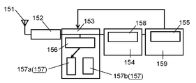
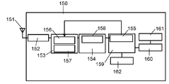
- the meter interface 150 shown in FIG. 1 includes at least an antenna 151, a matching unit 152, a matching adjustment unit 153, a transmission / reception circuit 154, a calculation unit 159, a count interface unit 160, a meter 161, and the like.
- the antenna 151 transmits and receives radio signals such as radio waves when communicating with the concentrator 100.
- the matching unit 152 matches the antenna 151 and the transmission / reception circuit 154.
- the matching adjustment unit 153 includes a changeover switch 156 and a plurality of matching components 157.
- the transmission / reception circuit 154 includes a level detection unit 158 that detects the strength of the radio signal transmitted from the concentrator 100.
- the calculation unit 159 includes a determination unit 155, and the determination unit 155 performs determination for switching the changeover switch 156 according to the level of the radio signal detected by the level detection unit.
- the antenna 151 may be completely built in the meter interface 150, or may be pulled out of the housing of the meter interface 150 as an external antenna. However, the state of the antenna 151 need not be specified.
- the matching unit 152 is composed of, for example, an inductor, a capacitive element, or the like.
- the matching unit 152 configures a circuit that performs impedance matching and phase conversion between the antenna 151 and the transmission / reception circuit 154.
- the transmission / reception circuit 154 constitutes a block that communicates with other short-range wireless devices including the concentrator 100.
- the transmission / reception circuit 154 includes, for example, a low noise amplifier, a detector, an oscillation circuit, a mixer, a phase synchronization circuit, a frequency divider, a modulation circuit, a power amplifier, a voltage control oscillation circuit, and a processor having the above functions. Is done.
- the transmission / reception circuit 154 includes a level detection unit 158 therein.
- the level detection unit 158 has a function of converting a signal input from the antenna 151 into a received signal strength level.
- the level detection unit 158 includes, for example, an analog-digital conversion circuit, a detection circuit, and an amplifier.
- the calculation unit 159 is constituted by, for example, a microcomputer, a storage for storing data and programs, and includes a determination unit 155 inside.
- the determination unit 155 performs control to switch the changeover switch 156 according to the signal level output from the level detection unit 158 of the transmission / reception circuit 154. At this time, the determination unit 155 performs switching control so that the signal received by the transmission / reception circuit 154 increases in accordance with the signal level output from the level detection unit 158. Note that the state where the signal level becomes high means that the impedance matching between the antenna 151 and the transmission / reception circuit 154 is selected to be optimum.
- the matching adjustment unit 153 includes a changeover switch 156 and a plurality of matching components 157.
- the changeover switch 156 is made of, for example, a compound semiconductor or a semiconductor such as a CMOS.
- the plurality of matching components 157 are configured with a capacitance component such as a plurality of capacitors (capacitance elements).
- the count interface unit 160 has a function of detecting the movement of the counter in the meter 161. Specifically, for example, a reed switch (ON / OFF state), a coil (voltage associated with fluctuations in inductor value), an electrostatic sensor (voltage value associated with capacitance fluctuations), an ultrasonic sensor (acoustic transmission / reception time), heat It is input to the count interface unit 160 directly or after signal processing from a detection sensor (voltage value associated with temperature change) or the like. Then, the counter movement detected by the count interface unit 160 is input to the calculation unit 159. The calculation unit 159 records, for example, as a flow rate or a cumulative flow rate.
- the meter 161 manages, for example, energy consumption and flow rate such as a gas meter, a water meter, a power meter, a current meter, a pressure meter, a flow meter, and a calorimeter.
- energy consumption and flow rate such as a gas meter, a water meter, a power meter, a current meter, a pressure meter, a flow meter, and a calorimeter.
- 1 shows a configuration in which the meter 161 is included in the same casing as the meter interface 150, it goes without saying that the meter 161 may be configured as a separate casing.
- a wireless system including the wireless device according to the present embodiment is constructed.
- FIG. 2 is a diagram showing a matching adjustment unit in the meter interface in the same embodiment.
- the matching adjustment unit 153 includes a changeover switch 156, a plurality of matching components 157, and the like.
- the changeover switch 156 is configured by, for example, a 1-input 2-output switch (Single Pole Double Throw).
- the changeover switch 156 is connected so that, for example, two types of matching components 157a and matching components 157b constituting the plurality of matching components 157 can be switched.
- matching component 157a and matching component 157b are standing waves depending on the meter interface 150 and its surrounding environment (for example, the distance to an obstacle), as described below with reference to FIG. It is composed of matching parts whose ratio changes.
- the matching component 157a and the matching component 157b are configured only by capacitive elements so that they can be easily switched. Therefore, phase conversion is performed via the phase conversion circuit of the matching unit 152.
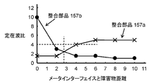
- FIG. 3 is a diagram showing characteristics of a plurality of matching parts in the same embodiment.
- the meter interface 150 has an optimum matching constant between the antenna 151 and the transmission / reception circuit 154 depending on the distance from an external obstacle. Therefore, in this embodiment, even if the distance to the obstacle changes, the component configurations and constants of the matching component 157a and the matching component 157b are set so that the standing wave ratio on the antenna 151 side is equal to or less than a predetermined value. Have decided. Specifically, as shown in FIG. 3, even if the distance between the meter interface 150 and an external obstacle changes, the alignment component 157a and the alignment component 157b can be switched at the boundary of the obstacle distance of 2.8. For example, the component configuration and the matching constant are set so that the standing wave ratio is 4 or less. If the target standing wave ratio cannot be realized by switching between two matching parts, a plurality of matching parts (not shown) other than the matching parts 157a and 157b are provided as the plurality of matching parts 157. May correspond.
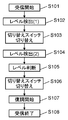
- FIG. 4 is a diagram for explaining a switching flow of the changeover switch in the embodiment. That is, FIG. 4 shows a switching flow of the changeover switch 156 of the alignment adjustment unit 153 in the meter interface 150.
- FIG. 4 illustrates an example of a flow when the meter interface 150 receives a message from another wireless device including the concentrator 100.
- the switch 156 in each wireless communication, the switch 156 is switched according to a predetermined protocol, and communication is performed with a message that secures a time sufficient to compare the reception levels of radio signals such as radio waves. It is assumed that
- the meter interface 150 first activates the transmission / reception circuit 154. As a result, the meter interface 150 starts receiving a message according to the determined protocol (step S101). At this time, the changeover switch 156 is set to be connected to a predetermined alignment component (in this embodiment, the alignment component 157a).
- the electronic message received via the predetermined matching component 157a is input to the level detection unit 158 of the transmission / reception circuit 154, and converted into a received signal strength level (RSSI (Received Signal Strength Indicator)) by the level detection unit 158 and output. To do. Then, the converted received signal strength level is stored in the calculation unit 159 (step S102). Note that the received signal strength level output from the level detector 158 may be simply referred to as a level.
- RSSI Receiveived Signal Strength Indicator
- the changeover switch 156 is switched at a predetermined timing in accordance with the determined protocol (step S103). At this time, it is switched and connected to a matching component (matching component 157b in the present embodiment) different from step S102.
- step S102 the electronic message received via the predetermined matching component 157b is input to the level detection unit 158 of the transmission / reception circuit 154, and converted into a received signal strength level by the level detection unit 158 and output. Then, the converted received signal strength level is stored in the calculation unit 159 (step S104).
- steps S102 and S104 the received signal strength levels stored in the calculation unit 159 are compared to determine the magnitude (step S105). Then, the changeover switch 156 is controlled to switch to the matching component side where the received signal strength level is large (step S106).
- a message demodulation operation is started via the transmission / reception circuit 154 and the calculation unit 159 (step S107).
- the switching procedure of the changeover switch 156 of the matching adjustment unit 153 is executed.
- the time and timing at which the meter interface 150 switches the changeover switch 156 is incorporated into the communication protocol.
- a message can be received with an optimum antenna matching.
- the plurality of matching components 157 are switched based on the received signal strength level converted by the level detection unit 158 in the transmission / reception circuit 154.
- the optimum component configuration and matching constant are determined from the plurality of matching components 157 in accordance with the meter interface 150 and the obstacles outside thereof. Therefore, the antenna 151 in the meter interface 150 can be optimized without providing a special circuit.
- the installation conditions of the meter interface 150 can be made uniform. Thereby, since anyone can install, installation cost can be suppressed.
- the configuration in which direct communication is performed between the concentrator 100 and the meter interface 150 has been described as an example, but the present invention is not limited to this.
- a configuration including a repeater serving as a relay or a configuration such as a multi-hop terminal may be used, and similar effects can be obtained.
- Embodiment 2 The configuration of the radio apparatus according to Embodiment 2 of the present invention will be described below using FIG. Specifically, another switching method of the changeover switch 156 in the meter interface 150 will be described.
- FIG. 5 is a block diagram of the meter interface according to the second embodiment of the present invention.
- the meter interface 150 of the present embodiment is different from the first embodiment in that it further includes a start switch.
- Other configurations and operations are the same as those in the first embodiment, and thus description thereof is omitted.
- the activation switch 162 of this embodiment constitutes a switch that is operated when the meter interface 150 is activated.
- the activation switch 162 is constituted by, for example, a tact switch, a slide switch, a reed switch that can be activated by a magnet, or the like.
- the meter interface 150 is driven by a primary battery such as a lithium battery. Therefore, the operation of the meter interface 150 is started by setting the start switch 162 to start after the meter interface 150 is installed. Thereby, power consumption can be suppressed and the life can be extended.
- FIG. 6 is a diagram for explaining an entry flow when the meter interface is installed in the embodiment.
- step S201 the transmission / reception circuit 154 is activated in order to enter the network constituting the wireless system.
- the calculation unit 159 generates a first entry message generated by a predetermined protocol. Then, the generated first entry message is transmitted to the concentrator 100 via the transmission / reception circuit 154 and the antenna 151. At this time, the changeover switch 156 of the matching adjustment unit 153 is set so as to be connected to a capacitive element constituting a predetermined matching component. (Step S202).
- the operation unit 102 when the concentrator 100 receives the transmitted first entry message, the operation unit 102 generates a first response message for the first entry message. Then, the concentrator 100 transmits the generated first response message to the meter interface 150 (step S203).
- the meter interface 150 receives the transmitted first response message by the transmission / reception circuit 154. Then, the level detection unit 158 converts the received signal strength level and stores it in the calculation unit 159.
- the meter interface 150 connects the changeover switch 156 to a capacitive element of a matching component different from that in step S202 (step S204).
- the meter interface 150 uses the calculation unit 159 to generate a second entry message. Then, the generated second entry message is transmitted to the concentrator 100 via the transmission / reception circuit 154 and the antenna 151 (step S205).
- the second response message for the second entry message is transmitted to the meter interface 150 (step S206).
- the meter interface 150 receives the transmitted second response message by the transmission / reception circuit 154. Then, the level detection unit 158 converts the received intensity signal level and stores it in the calculation unit 159.
- steps S204 and S206 the received signal strength levels stored in the calculation unit 159 are compared to determine the magnitude. Then, the selector switch 156 is switched and set to the matching component side where the received signal strength level is large (step S207).
- the switching procedure of the changeover switch 156 of the present embodiment is executed.
- a meter interface when a meter interface is installed and connected to another wireless device such as a concentrator through a network, matching components are switched and a received signal strength level is detected a plurality of times. Then, the matching component having the larger received signal strength level is set.
- robust communication can be performed without being affected by the installation environment of the meter interface.
- the meter interface can be installed with uniform rules. As a result, the installation work of the meter interface can be simplified.
- the method of receiving the received signal strength level at a plurality of times described above generally depends on the protocol. Therefore, the switching method shown above is only an example.
- the meter interface is activated by the activation switch, and then the operation proceeds to a continuous beacon reception operation.
- a plurality of beacons are received from a plurality of matching circuits while switching matching constants.
- the received signal strength level received by the level detection unit of the transmission / reception circuit may be compared to select a matching circuit having the highest reception level.
- a determination may be made using not only the received signal strength level but also information on the number of relay stages. In this case, if it is equal to or greater than the threshold value, the information on the number of relay stages is given priority over the received signal strength level, and for example, the route with the minimum number of relay stages is determined. On the other hand, when the value is equal to or less than the threshold, the received signal strength level is controlled with priority. Thereby, suppression of consumption current and high communication responsiveness can be made compatible.
- Embodiment 3 The configuration of the radio apparatus according to Embodiment 3 of the present invention will be described below using FIG. Specifically, a method for switching the changeover switch 156 in the meter interface will be described.
- FIG. 7 is a diagram for explaining a communication flow between the meter interface and the concentrator in the third embodiment of the present invention.
- the present embodiment is different from the first and second embodiments in that it includes a processing operation when an abnormality occurs in communication between the meter interface and the concentrator.
- Other configurations and operations are the same as those in the first and second embodiments, and thus description thereof is omitted.
- the periodic communication is communication for raising the meter reading value acquired from the meter 161 to the concentrator 100 and the server, for example.
- the abnormality of the meter 161 or the meter interface 150 is, for example, a battery voltage drop alarm, a hardware error, or an unauthorized use.
- the meter interface 150 generates a message by the calculation unit 159 according to a predetermined protocol. And the produced
- the concentrator 100 transmits a response message or an ACK signal to the meter interface 150 (step S302).
- the meter interface 150 can determine that the communication is successful.
- a telegram is transmitted from the meter interface 150 to the concentrator 100 (step S303).
- the meter interface 150 retransmits the message a predetermined number of times after a predetermined time has elapsed (step S304). S305).
- the changeover switch 156 in the matching adjustment unit 153 is switched. At this time, the changeover switch 156 is controlled so as to be connected to another matching part from the matching part connected in steps S303 to S305 (step S307).
- the meter interface 150 transmits the generated message again to the concentrator 100 (step S308).
- the communication conditions with the non-existing concentrator can be changed by appropriately changing the plurality of matching parts 157 of the meter interface 150 as in the present embodiment. For this reason, after the meter interface is installed, it is possible to cope with the case where the environmental conditions change and communication becomes impossible. Thereby, there is no need to perform communication robustness or change the installation position of the meter interface. As a result, maintainability can be improved and network operation costs can be suppressed.
- the received signal strength level can be periodically acquired and compared with the previous communication at the time of installation. That is, when the received signal strength level is greatly deteriorated, the changeover switch 156 is switched, and the determination unit 155 compares and changes the setting to the optimum matching component. Thereby, the robustness of communication can be improved. Furthermore, it is advantageous in terms of component cost and miniaturization as compared with a method of realizing diversity by using a plurality of antennas.
- the wireless device of the present invention includes an antenna that transmits and receives wireless signals, a transmission / reception circuit, a matching unit that has a function of matching between the antenna and the transmission / reception circuit, and a phase adjustment function.
- a matching adjustment unit including a changeover switch and a plurality of matching parts, and a level detection unit that detects a reception level of a radio signal received via the antenna are provided.
- a determination unit that switches a changeover switch of the matching adjustment unit according to the level output from the level detection unit may be provided.
- the matching unit may be composed of only a capacitive element and an inductor, and a plurality of matching parts may be composed of only the capacitive element in the matching adjustment unit.
- the determination unit of the wireless device of the present invention may perform control so as to switch a changeover switch in the matching adjustment unit and select a switching state in which the reception level output from the level detection unit is high.
- the determination unit of the wireless device of the present invention switches the changeover switch in the matching adjustment unit at least once when installing the wireless device, and selects a switching state in which the reception level output from the level detection unit is high, You may comprise so that subsequent communication may be performed.
- the determination unit of the wireless device of the present invention may be configured to perform communication again by switching the changeover switch in the matching adjustment unit when communication becomes impossible after communication with another wireless device.
- the wireless device of the present invention may further include an activation switch, and the determination unit may perform the switching operation of the changeover switch of the matching adjustment unit after the activation switch is activated. Thereby, power consumption can be suppressed and the life can be extended.
- the wireless device of the present invention can be installed in an optimum state of antenna performance at the time of installation. Therefore, it is useful for a wireless device used in a fixed manner.
Abstract
A radio apparatus comprises: an antenna (151) for transmitting/receiving radio signals; and a matching unit (152) having a function of adjusting phase/matching between the antenna (151) and a transmission/reception circuit (154). In order to change the matching status of the antenna (151), the radio apparatus further comprises: a changeover switch (156); a matching adjustment unit (153); and a level detection unit (158) included in the transmission/reception circuit (154) for detecting the reception level of a radio signal received via the antenna (151). The radio apparatus is still further constituted by a determination unit (155) for changing, in accordance with the level outputted from the level detection unit (158), the setting of the changeover switch (156) of the matching adjustment unit (153). In this way, a radio apparatus capable of providing an optimum radio performance at the time of installation thereof or even thereafter can be achieved.
Description
本発明は、設置環境やその変化に対し、アンテナを最適に制御する無線装置に関する。
The present invention relates to a wireless device that optimally controls an antenna with respect to an installation environment and changes thereof.
一般的に、無線装置内のアンテナは、周囲環境に影響を受けることが多い。そのため、周囲環境によっては、無線装置の通信性能や消費電流の増減に大きく影響する。そこで、従来、特に無線装置のアンテナに影響を及ぼす金属材との距離を検出する仕組みを入れ、検出距離に応じてアンテナの整合回路を切り替える無線装置が開示されている(例えば、特許文献1参照)。これにより、周囲環境の影響を緩和している。
Generally, antennas in wireless devices are often affected by the surrounding environment. Therefore, depending on the surrounding environment, it greatly affects the communication performance and increase / decrease of current consumption of the wireless device. Therefore, conventionally, a wireless device that includes a mechanism for detecting a distance from a metal material that particularly affects the antenna of the wireless device and switches the matching circuit of the antenna in accordance with the detected distance has been disclosed (see, for example, Patent Document 1). ). This reduces the influence of the surrounding environment.
また、無線装置内の送受信回路とは別に、反射波を検出するブロックを具備し、周囲環境に応じた反射波を検出する方法なども開示されている(例えば、特許文献2、特許文献3参照)。
In addition to the transmission / reception circuit in the wireless device, a method of detecting a reflected wave according to the surrounding environment by including a block for detecting a reflected wave is also disclosed (see, for example, Patent Document 2 and Patent Document 3). ).
しかしながら、従来の無線装置の方法では、周囲環境を検出する装置や、反射波を検出する特別な装置が必要となる。そのため、無線装置の小型化や、コスト面で不利になる。
However, the conventional wireless device method requires a device for detecting the surrounding environment and a special device for detecting reflected waves. This is disadvantageous in terms of downsizing and cost of the wireless device.
また、周囲環境を検出する装置は、装置の配置の仕方によっては、周囲環境を正確に検出できないこともある。特に、無線装置が固定局の場合、無線装置を一旦設置すると、設置場所を動かすことがない。つまり、無線装置は、設置された周囲環境の影響を受け続けることになる。そのため、無線装置を含むシステムの伝搬距離、通信のロバスト性、カバーエリアに起因する経済性が悪くなるなどの大きな課題があった。
Also, the device that detects the surrounding environment may not be able to accurately detect the surrounding environment depending on the arrangement of the device. In particular, when the wireless device is a fixed station, once the wireless device is installed, the installation location does not move. That is, the wireless device continues to be affected by the surrounding environment in which it is installed. For this reason, there are major problems such as the propagation distance of the system including the wireless device, the robustness of communication, and the economical efficiency due to the cover area.
また、無線装置に、1次電池などの電池を使用する場合、周囲環境を検出するための専用の装置や、反射波を検出するブロックを追加すると、消費電流などが増加する。その結果、無線装置の製品寿命が短くなる虞があった。
In addition, when a battery such as a primary battery is used as a wireless device, current consumption increases if a dedicated device for detecting the surrounding environment or a block for detecting reflected waves is added. As a result, the product life of the wireless device may be shortened.
本発明の無線装置は、送受信回路内に無線信号の受信レベルを検出するレベル検出部を有する。レベル検出部は、無線装置の外部から送信される無線信号の受信レベルを検出する。そして、無線信号の受信レベルに応じて、アンテナ以後に配置した切り替えスイッチで、整合調整部を調整する構成を備える。
The wireless device of the present invention has a level detection unit for detecting the reception level of the wireless signal in the transmission / reception circuit. The level detection unit detects a reception level of a radio signal transmitted from the outside of the radio apparatus. And it has the structure which adjusts a matching adjustment part with the changeover switch arrange | positioned after an antenna according to the reception level of a radio signal.
これにより、無線装置のアンテナを、設置環境に合わせて最適に制御できる。つまり、本発明の無線装置は、外部より送信される無線信号の受信レベルを検出して、設置環境を把握し、アンテナの整合を最適化する。その結果、無線装置の小型化、コスト抑制、消費電流の抑制を維持しながら、ロバストな無線通信を維持できる。
This makes it possible to optimally control the antenna of the wireless device according to the installation environment. That is, the radio apparatus of the present invention detects the reception level of radio signals transmitted from the outside, grasps the installation environment, and optimizes antenna matching. As a result, it is possible to maintain robust wireless communication while maintaining downsizing of the wireless device, cost reduction, and current consumption.
以下、本発明の実施の形態について、図面を参照しながら説明する。なお、この実施の形態によって本発明を限定されるものではない。
Hereinafter, embodiments of the present invention will be described with reference to the drawings. Note that the present invention is not limited to the embodiments.
(実施の形態1)
まず、本発明の実施の形態1における無線システムについて、図1を用いて説明する。 (Embodiment 1)
First, the radio system inEmbodiment 1 of this invention is demonstrated using FIG.
まず、本発明の実施の形態1における無線システムについて、図1を用いて説明する。 (Embodiment 1)
First, the radio system in
図1は、本発明の実施の形態1における無線システムを示す図である。
FIG. 1 is a diagram showing a radio system according to Embodiment 1 of the present invention.
図1に示すように、本実施の形態の無線システムは、少なくともコンセントレータ100とメータインターフェイス150の2種類の無線装置により構成される。
As shown in FIG. 1, the wireless system of the present embodiment includes at least two types of wireless devices, a concentrator 100 and a meter interface 150.
コンセントレータ100は、少なくとも長距離無線部101と、演算部102と、短距離無線部103と、基準クロック生成部104と、レベル演算部105と、設置情報記憶部106などを備える。長距離無線部101は、長距離の通信を行うデバイスで構成される。演算部102は、両無線部間で予め定められたプロトコルあるいは仕様で通信を行うように制御する。短距離無線部103は、後述するメータインターフェイス150と通信を行う。基準クロック生成部104は、メータインターフェイス150と通信を行う際に同期して通信するための、基準タイミングを生成する。レベル演算部105は、メータインターフェイス150から送信され、短距離無線部103で受信された信号の信号レベルを算出する。
The concentrator 100 includes at least a long-range wireless unit 101, a calculation unit 102, a short-range wireless unit 103, a reference clock generation unit 104, a level calculation unit 105, an installation information storage unit 106, and the like. The long distance wireless unit 101 is configured by a device that performs long distance communication. The arithmetic unit 102 performs control so that communication is performed between the wireless units using a predetermined protocol or specification. The short-range wireless unit 103 communicates with a meter interface 150 described later. The reference clock generation unit 104 generates a reference timing for communicating in synchronization with the meter interface 150 when communicating. Level calculation unit 105 calculates the signal level of the signal transmitted from meter interface 150 and received by short-range radio unit 103.
なお、コンセントレータ100内の長距離無線部101は、携帯電話などで使用される規格に準拠した無線ユニットで構成される。長距離無線部101の無線ユニットは、例えばGSM(Global System for Mobile Communications)(登録商標)、GPRS(General Packet Radio Service)、EDGE(Enhanced Data GSM Environment)などで構成される。具体的には、長距離無線部101は、例えばアンテナ、ローノイズアンプ、検波器、発振回路、ミクサ、位相同期回路、分周器、復調回路、変調回路、パワーアンプ、電圧制御発振回路および、上記機能を有するプロセッサなどから構成される。
Note that the long-distance wireless unit 101 in the concentrator 100 is composed of a wireless unit that conforms to a standard used for mobile phones and the like. The wireless unit of the long-distance wireless unit 101 is, for example, GSM (Global System for Mobile Communications) (registered trademark), GPRS (General Packet Radio Service), EDGE (Enhanced Data GSM Environment, etc.). Specifically, the long-range wireless unit 101 includes, for example, an antenna, a low noise amplifier, a detector, an oscillation circuit, a mixer, a phase synchronization circuit, a frequency divider, a demodulation circuit, a modulation circuit, a power amplifier, a voltage control oscillation circuit, and the above It is composed of a processor having a function.
そして、長距離無線部101は、公共回線やネットワークを介して、管理用サーバーなどに接続される。このとき、管理用サーバーは、接続されたコンセントレータ100の状態監視や、操作、管理などを行う。
The long distance wireless unit 101 is connected to a management server or the like via a public line or a network. At this time, the management server performs status monitoring, operation, management, and the like of the connected concentrator 100.
短距離無線部103は、長距離無線部101と比較して、送信出力が同等かあるいは小さい。そのため、短距離無線部103は、下位側に接続されるメータインターフェイス150と通信を行う通信部分を構成する。なお、下位側とは短距離無線部からメータインターフェイスの通信で、上位側とはコンセントレータの中の長距離無線部を使った通信(コンセントレータからサーバー)を意味する。
The short-range radio unit 103 has a transmission output equal to or smaller than that of the long-range radio unit 101. Therefore, the short-range wireless unit 103 constitutes a communication part that communicates with the meter interface 150 connected to the lower side. The lower side means communication from the short-range radio unit to the meter interface, and the upper side means communication using the long-range radio unit in the concentrator (concentrator to server).
具体的には、短距離無線部103は、例えばアンテナ、ローノイズアンプ、検波器、発振回路、ミクサ、位相同期回路、分周器、復調回路、変調回路、パワーアンプ、電圧制御発振回路および、上記機能を有するプロセッサなどから構成される。
Specifically, the short-range wireless unit 103 includes, for example, an antenna, a low noise amplifier, a detector, an oscillation circuit, a mixer, a phase synchronization circuit, a frequency divider, a demodulation circuit, a modulation circuit, a power amplifier, a voltage control oscillation circuit, and the above It is composed of a processor having a function.
レベル演算部105は、例えばアナログ-デジタル変換回路、比較器、検波回路、クロック回路、演算回路などで構成される。そして、レベル演算部105は、短距離無線部103で受信した、例えばメータインターフェイス150からの信号レベルを演算(算出)する。
The level calculation unit 105 includes, for example, an analog-digital conversion circuit, a comparator, a detection circuit, a clock circuit, and an arithmetic circuit. The level calculation unit 105 calculates (calculates) the signal level received by the short-range wireless unit 103, for example, from the meter interface 150.
設置情報記憶部106は、例えば不揮発性メモリやマイクロコンピュータなどで構成される。そして、設置情報記憶部106は、コンセントレータ100の設置高さ、周囲状況あるいは環境などの設置情報を記憶する。
The installation information storage unit 106 includes, for example, a nonvolatile memory or a microcomputer. Then, the installation information storage unit 106 stores installation information such as the installation height of the concentrator 100, the surrounding situation, or the environment.
演算部102は、例えばマイクロコンピュータや、データやプログラムを蓄積するストレージなどで構成される。そして、演算部102は、コンセントレータ100の長距離無線部101で受信した上位(管理サーバーなど)からの命令に応じて、コンセントレータ100の状態を制御する。さらに、演算部102は、下位のメータインターフェイス150のアンテナ151、送受信回路154を介して、メータ161の情報を取得する。
The calculation unit 102 is constituted by, for example, a microcomputer and a storage for storing data and programs. Then, the arithmetic unit 102 controls the state of the concentrator 100 in accordance with a command from a host (such as a management server) received by the long-distance wireless unit 101 of the concentrator 100. Furthermore, the calculation unit 102 acquires information on the meter 161 via the antenna 151 and the transmission / reception circuit 154 of the lower-level meter interface 150.
また、図1に示すメータインターフェイス150は、少なくともアンテナ151と、整合部152と、整合調整部153と、送受信回路154と、演算部159と、カウントインターフェイス部160と、メータ161などで構成される。アンテナ151は、コンセントレータ100と通信を行う際、電波などの無線信号を送受信する。整合部152は、アンテナ151と送受信回路154とを整合させる。整合調整部153は、切り替えスイッチ156と複数の整合部品157で構成される。送受信回路154は、コンセントレータ100から送信される無線信号の強度を検出するレベル検出部158を備える。演算部159は、判断部155を備え、判断部155はレベル検出部で検出される無線信号のレベルに応じて、切り替えスイッチ156を切り替えるための判断を行う。
The meter interface 150 shown in FIG. 1 includes at least an antenna 151, a matching unit 152, a matching adjustment unit 153, a transmission / reception circuit 154, a calculation unit 159, a count interface unit 160, a meter 161, and the like. . The antenna 151 transmits and receives radio signals such as radio waves when communicating with the concentrator 100. The matching unit 152 matches the antenna 151 and the transmission / reception circuit 154. The matching adjustment unit 153 includes a changeover switch 156 and a plurality of matching components 157. The transmission / reception circuit 154 includes a level detection unit 158 that detects the strength of the radio signal transmitted from the concentrator 100. The calculation unit 159 includes a determination unit 155, and the determination unit 155 performs determination for switching the changeover switch 156 according to the level of the radio signal detected by the level detection unit.
なお、アンテナ151は、メータインターフェイス150に完全に内蔵される場合と、外部アンテナとしてメータインターフェイス150の筐体から引き出されている場合とがある。しかし、アンテナ151の状態を、特に規定する必要はない。
The antenna 151 may be completely built in the meter interface 150, or may be pulled out of the housing of the meter interface 150 as an external antenna. However, the state of the antenna 151 need not be specified.
整合部152は、例えばインダクタ、容量素子などで構成される。そして、整合部152は、アンテナ151と送受信回路154とのインピーダンス整合および位相変換を行う回路を構成する。
The matching unit 152 is composed of, for example, an inductor, a capacitive element, or the like. The matching unit 152 configures a circuit that performs impedance matching and phase conversion between the antenna 151 and the transmission / reception circuit 154.
送受信回路154は、コンセントレータ100を含む他の短距離無線機と通信するブロックを構成する。具体的には、送受信回路154は、例えばローノイズアンプ、検波器、発振回路、ミクサ、位相同期回路、分周器、変調回路、パワーアンプ、電圧制御発振回路および、上記機能を有するプロセッサなどから構成される。
The transmission / reception circuit 154 constitutes a block that communicates with other short-range wireless devices including the concentrator 100. Specifically, the transmission / reception circuit 154 includes, for example, a low noise amplifier, a detector, an oscillation circuit, a mixer, a phase synchronization circuit, a frequency divider, a modulation circuit, a power amplifier, a voltage control oscillation circuit, and a processor having the above functions. Is done.
さらに、送受信回路154は、内部にレベル検出部158を備える。レベル検出部158は、アンテナ151から入力される信号を受信信号強度レベルに変換する機能を有する。レベル検出部158は、例えばアナログ-デジタル変換回路、検波回路、アンプなどで構成される。
Furthermore, the transmission / reception circuit 154 includes a level detection unit 158 therein. The level detection unit 158 has a function of converting a signal input from the antenna 151 into a received signal strength level. The level detection unit 158 includes, for example, an analog-digital conversion circuit, a detection circuit, and an amplifier.
演算部159は、例えばマイクロコンピュータや、データやプログラムを蓄積するストレージなどで構成され、内部に判断部155を備える。判断部155は、送受信回路154のレベル検出部158から出力された信号レベルに応じて、切り替えスイッチ156を切り替える制御を行う。このとき、判断部155は、レベル検出部158から出力される信号レベルに応じて、送受信回路154で受信する信号が大きくなるように切り替え制御を行う。なお、信号レベルが大きくなる状態は、アンテナ151と送受信回路154のインピーダンス整合が最適になるように選択されていることを意味する。
The calculation unit 159 is constituted by, for example, a microcomputer, a storage for storing data and programs, and includes a determination unit 155 inside. The determination unit 155 performs control to switch the changeover switch 156 according to the signal level output from the level detection unit 158 of the transmission / reception circuit 154. At this time, the determination unit 155 performs switching control so that the signal received by the transmission / reception circuit 154 increases in accordance with the signal level output from the level detection unit 158. Note that the state where the signal level becomes high means that the impedance matching between the antenna 151 and the transmission / reception circuit 154 is selected to be optimum.
整合調整部153は、切り替えスイッチ156と複数の整合部品157とで構成される。切り替えスイッチ156は、例えば化合物半導体またはCMOSなどの半導体で構成される。複数の整合部品157は、複数のコンデンサ(容量素子)などの容量成分で構成される。
The matching adjustment unit 153 includes a changeover switch 156 and a plurality of matching components 157. The changeover switch 156 is made of, for example, a compound semiconductor or a semiconductor such as a CMOS. The plurality of matching components 157 are configured with a capacitance component such as a plurality of capacitors (capacitance elements).
カウントインターフェイス部160は、メータ161内のカウンターの動きを検出する機能を有する。具体的には、例えばリードスイッチ(ON/OFF状態)、コイル(インダクタ値の変動に伴う電圧)、静電センサ(容量変動に伴う電圧値)、超音波センサ(超音波の送受信時間)、熱検出センサ(温度変化に伴う電圧値)などから、直接、あるいは信号処理後に、カウントインターフェイス部160に入力される。そして、カウントインターフェイス部160で検出されたカウンターの動きは、演算部159に入力される。演算部159は、例えば流量、累積流量などとして記録する。
The count interface unit 160 has a function of detecting the movement of the counter in the meter 161. Specifically, for example, a reed switch (ON / OFF state), a coil (voltage associated with fluctuations in inductor value), an electrostatic sensor (voltage value associated with capacitance fluctuations), an ultrasonic sensor (acoustic transmission / reception time), heat It is input to the count interface unit 160 directly or after signal processing from a detection sensor (voltage value associated with temperature change) or the like. Then, the counter movement detected by the count interface unit 160 is input to the calculation unit 159. The calculation unit 159 records, for example, as a flow rate or a cumulative flow rate.
メータ161は、例えばガスメータ、水道メータ、電力メータ、電流メータ、圧力メータ、流量メータ、カロリーメータなどの、エネルギーの消費量や流量などを管理する。なお、図1では、メータ161がメータインターフェイス150と同じ筐体に入っている構成を示しているが、別々の筐体で構成してもよいことはいうまでもない。
The meter 161 manages, for example, energy consumption and flow rate such as a gas meter, a water meter, a power meter, a current meter, a pressure meter, a flow meter, and a calorimeter. 1 shows a configuration in which the meter 161 is included in the same casing as the meter interface 150, it goes without saying that the meter 161 may be configured as a separate casing.
以上のように、本実施の形態の無線装置を含む無線システムが構築されている。
As described above, a wireless system including the wireless device according to the present embodiment is constructed.
つぎに、メータインターフェイス150内の整合調整部153の構成について、図2を参照しながら説明する。
Next, the configuration of the alignment adjustment unit 153 in the meter interface 150 will be described with reference to FIG.
図2は、同実施の形態におけるメータインターフェイス内の整合調整部を示す図である。
FIG. 2 is a diagram showing a matching adjustment unit in the meter interface in the same embodiment.
図2に示すように、整合調整部153は、切り替えスイッチ156と、複数の整合部品157などから構成される。切り替えスイッチ156は、例えば1入力2出力スイッチ(Single Pole Double Throw)で構成される。そして、切り替えスイッチ156は、複数の整合部品157を構成する、例えば2種類の整合部品157aと整合部品157bとを切り替え可能に接続される。
As shown in FIG. 2, the matching adjustment unit 153 includes a changeover switch 156, a plurality of matching components 157, and the like. The changeover switch 156 is configured by, for example, a 1-input 2-output switch (Single Pole Double Throw). The changeover switch 156 is connected so that, for example, two types of matching components 157a and matching components 157b constituting the plurality of matching components 157 can be switched.
なお、2種類の整合部品157aと整合部品157bは、図3を用いて以下で説明するように、メータインターフェイス150と、その周辺環境(例えば、障害物との距離)に応じて、定在波比が変化する整合部品で構成している。本実施の形態では、整合部品157aと整合部品157bは、容易に切り替えられるように容量素子のみで構成している。そのため、整合部152の位相変換回路を介して位相変換を行っている。
Note that the two types of matching component 157a and matching component 157b are standing waves depending on the meter interface 150 and its surrounding environment (for example, the distance to an obstacle), as described below with reference to FIG. It is composed of matching parts whose ratio changes. In the present embodiment, the matching component 157a and the matching component 157b are configured only by capacitive elements so that they can be easily switched. Therefore, phase conversion is performed via the phase conversion circuit of the matching unit 152.
つぎに、上述した2種類の整合部品157aと整合部品157bの部品構成と整合定数の設定方法について、図3を用いて説明する。
Next, a method of setting the component configuration and the matching constant of the two types of matching component 157a and matching component 157b described above will be described with reference to FIG.
図3は、同実施の形態における複数の整合部品の特性を示す図である。
FIG. 3 is a diagram showing characteristics of a plurality of matching parts in the same embodiment.
通常、メータインターフェイス150は、外部の障害物との距離に応じて、アンテナ151と送受信回路154間の最適な整合定数が異なる。そこで、本実施の形態では、障害物との距離が変化しても、アンテナ151側の定在波比を予め決められた数値以下になるように整合部品157aと整合部品157bの部品構成と定数を決めている。具体的には、図3に示すように、メータインターフェイス150と外部の障害物の距離が変化しても、障害物との距離が2.8を境に、整合部品157aと整合部品157bを切り替えれば、定在波比が4以下になるように部品構成と整合定数を設定した。なお、目標の定在波比が、2つの整合部品の切り替えで実現できない場合、複数の整合部品157として、整合部品157a、157b以外に、図示しない、さらに別の複数個の整合部品を設けて対応してもよい。
Normally, the meter interface 150 has an optimum matching constant between the antenna 151 and the transmission / reception circuit 154 depending on the distance from an external obstacle. Therefore, in this embodiment, even if the distance to the obstacle changes, the component configurations and constants of the matching component 157a and the matching component 157b are set so that the standing wave ratio on the antenna 151 side is equal to or less than a predetermined value. Have decided. Specifically, as shown in FIG. 3, even if the distance between the meter interface 150 and an external obstacle changes, the alignment component 157a and the alignment component 157b can be switched at the boundary of the obstacle distance of 2.8. For example, the component configuration and the matching constant are set so that the standing wave ratio is 4 or less. If the target standing wave ratio cannot be realized by switching between two matching parts, a plurality of matching parts (not shown) other than the matching parts 157a and 157b are provided as the plurality of matching parts 157. May correspond.
つぎに、整合調整部153の切り替えスイッチ156の切り替え手順について、図4を用いて、以下で説明する。
Next, the switching procedure of the changeover switch 156 of the matching adjustment unit 153 will be described below with reference to FIG.
図4は、同実施の形態における切り替えスイッチの切り替えフローを説明する図である。つまり、図4は、メータインターフェイス150において、整合調整部153の切り替えスイッチ156の切り替えフローを示している。また、図4では、メータインターフェイス150が、コンセントレータ100を含む他の無線装置からの電文を受信する際のフローを例に示している。ここで、図4のフローは、予め決められたプロトコルにより、各無線通信において、切り替えスイッチ156を切り替え、電波などの無線信号の受信レベルを比較するだけの時間を確保した電文で通信を行うように決められているとして説明する。
FIG. 4 is a diagram for explaining a switching flow of the changeover switch in the embodiment. That is, FIG. 4 shows a switching flow of the changeover switch 156 of the alignment adjustment unit 153 in the meter interface 150. FIG. 4 illustrates an example of a flow when the meter interface 150 receives a message from another wireless device including the concentrator 100. Here, in the flow of FIG. 4, in each wireless communication, the switch 156 is switched according to a predetermined protocol, and communication is performed with a message that secures a time sufficient to compare the reception levels of radio signals such as radio waves. It is assumed that
図4に示すように、メータインターフェイス150は、まず、送受信回路154を起動する。これにより、メータインターフェイス150は、決められたプロトコルに応じて、電文の受信を開始する(ステップS101)。このとき、切り替えスイッチ156は、所定の整合部品(本実施の形態では、整合部品157a)に接続するように設定されている。
As shown in FIG. 4, the meter interface 150 first activates the transmission / reception circuit 154. As a result, the meter interface 150 starts receiving a message according to the determined protocol (step S101). At this time, the changeover switch 156 is set to be connected to a predetermined alignment component (in this embodiment, the alignment component 157a).
つぎに、所定の整合部品157aを介して受信した電文を送受信回路154のレベル検出部158に入力し、レベル検出部158で受信信号強度レベル(RSSI(Recived Signal Strength Indicator))に変換して出力するする。そして、変換した受信信号強度レベルを、演算部159に記憶する(ステップS102)。なお、レベル検出部158から出力される受信信号強度レベルを、単にレベルと記す場合がある。
Next, the electronic message received via the predetermined matching component 157a is input to the level detection unit 158 of the transmission / reception circuit 154, and converted into a received signal strength level (RSSI (Received Signal Strength Indicator)) by the level detection unit 158 and output. To do. Then, the converted received signal strength level is stored in the calculation unit 159 (step S102). Note that the received signal strength level output from the level detector 158 may be simply referred to as a level.
つぎに、決められたプロトコルに従って、所定のタイミングで切り替えスイッチ156を切り替える(ステップS103)。このとき、ステップS102とは異なる整合部品(本実施の形態では、整合部品157b)に切り替えて接続される。
Next, the changeover switch 156 is switched at a predetermined timing in accordance with the determined protocol (step S103). At this time, it is switched and connected to a matching component (matching component 157b in the present embodiment) different from step S102.
つぎに、ステップS102と同様に、所定の整合部品157bを介して受信した電文を送受信回路154のレベル検出部158へ入力し、レベル検出部158で受信信号強度レベルに変換して出力する。そして、変換した受信信号強度レベルを、演算部159に記憶する(ステップS104)。
Next, as in step S102, the electronic message received via the predetermined matching component 157b is input to the level detection unit 158 of the transmission / reception circuit 154, and converted into a received signal strength level by the level detection unit 158 and output. Then, the converted received signal strength level is stored in the calculation unit 159 (step S104).
つぎに、ステップS102、S104で、演算部159に記憶した受信信号強度レベルを比較して、大小を判断する(ステップS105)。そして、受信信号強度レベルが大きい整合部品側へ、切り替えスイッチ156を制御して切り替える(ステップS106)。
Next, in steps S102 and S104, the received signal strength levels stored in the calculation unit 159 are compared to determine the magnitude (step S105). Then, the changeover switch 156 is controlled to switch to the matching component side where the received signal strength level is large (step S106).
つぎに、送受信回路154および演算部159を介して、電文の復調動作を開始する(ステップS107)。
Next, a message demodulation operation is started via the transmission / reception circuit 154 and the calculation unit 159 (step S107).
そして、復調動作が終了すると、電文の受信を終了する(ステップS108)。
Then, when the demodulation operation is finished, the reception of the message is finished (step S108).
以上のように、整合調整部153の切り替えスイッチ156の切り替え手順が実行される。
As described above, the switching procedure of the changeover switch 156 of the matching adjustment unit 153 is executed.
つまり、本実施の形態では、メータインターフェイス150がコンセントレータ100を含む他の無線装置と通信する際、通信プロトコルに、メータインターフェイス150が切り替えスイッチ156を切り替える時間およびタイミングを組み込む。これにより、常に、メータインターフェイス150が設置される環境において、最適なアンテナ整合で電文を受信することができる。その結果、通信距離の低下、再送回数やアンテナ整合ズレによる消費電流の増加抑制、および通信のロバスト性を確保できる。
That is, in this embodiment, when the meter interface 150 communicates with other wireless devices including the concentrator 100, the time and timing at which the meter interface 150 switches the changeover switch 156 is incorporated into the communication protocol. As a result, in an environment where the meter interface 150 is installed, a message can be received with an optimum antenna matching. As a result, it is possible to secure a reduction in communication distance, suppression of increase in current consumption due to the number of retransmissions and antenna alignment shift, and communication robustness.
また、本実施の形態では、送受信回路154内のレベル検出部158で変換した受信信号強度レベルから判断し、複数の整合部品157の切り替えを行っている。これにより、メータインターフェイス150とその外部の障害物に応じて、複数の整合部品157から最適な部品構成や整合定数を決定している。そのため、特別な回路を別に設けることなく、メータインターフェイス150内のアンテナ151の最適化を図ることができる。
Further, in the present embodiment, the plurality of matching components 157 are switched based on the received signal strength level converted by the level detection unit 158 in the transmission / reception circuit 154. Thus, the optimum component configuration and matching constant are determined from the plurality of matching components 157 in accordance with the meter interface 150 and the obstacles outside thereof. Therefore, the antenna 151 in the meter interface 150 can be optimized without providing a special circuit.
また、本実施の形態では、周囲環境の影響を受けにくくなるので、メータインターフェイス150の設置条件を、画一的にできる。これにより、誰にでも設置が可能になるため、設置コストを抑制できる。
Moreover, in this embodiment, since it becomes difficult to be influenced by the surrounding environment, the installation conditions of the meter interface 150 can be made uniform. Thereby, since anyone can install, installation cost can be suppressed.
なお、上記実施の形態では、コンセントレータ100とメータインターフェイス150間で、直接通信する構成を例に説明したが、これに限られない。例えば、中継の役割を果たすリピータが入った構成や、マルチホップする端末などの構成でもよく、同様の効果が得られる。
In the above embodiment, the configuration in which direct communication is performed between the concentrator 100 and the meter interface 150 has been described as an example, but the present invention is not limited to this. For example, a configuration including a repeater serving as a relay or a configuration such as a multi-hop terminal may be used, and similar effects can be obtained.
(実施の形態2)
以下に、本発明の実施の形態2における無線装置の構成について、図5を用いて説明する。具体的には、メータインターフェイス150内の切り替えスイッチ156の別の切り替え方法について、説明する。 (Embodiment 2)
The configuration of the radio apparatus according toEmbodiment 2 of the present invention will be described below using FIG. Specifically, another switching method of the changeover switch 156 in the meter interface 150 will be described.
以下に、本発明の実施の形態2における無線装置の構成について、図5を用いて説明する。具体的には、メータインターフェイス150内の切り替えスイッチ156の別の切り替え方法について、説明する。 (Embodiment 2)
The configuration of the radio apparatus according to
図5は、本発明の実施の形態2におけるメータインターフェイスのブロック図である。
FIG. 5 is a block diagram of the meter interface according to the second embodiment of the present invention.
なお、以下では、実施の形態1のメータインターフェイスと異なる部分について、詳細に説明する。
In the following, portions different from the meter interface of the first embodiment will be described in detail.
図5に示すように、本実施の形態のメータインターフェイス150は、さらに起動スイッチを備える点で、実施の形態1とは異なる。他の構成や動作は、実施の形態1と同様であるので、説明を省略する。
As shown in FIG. 5, the meter interface 150 of the present embodiment is different from the first embodiment in that it further includes a start switch. Other configurations and operations are the same as those in the first embodiment, and thus description thereof is omitted.
つまり、本実施の形態の起動スイッチ162は、メータインターフェイス150を起動する際、操作するスイッチを構成する。起動スイッチ162は、例えばタクトスイッチ、スライドスイッチ、磁石などで起動できるリードスイッチなどで構成される。
That is, the activation switch 162 of this embodiment constitutes a switch that is operated when the meter interface 150 is activated. The activation switch 162 is constituted by, for example, a tact switch, a slide switch, a reed switch that can be activated by a magnet, or the like.
ここで、メータインターフェイス150は、例えばリチウム電池などの1次電池で駆動される。そのため、メータインターフェイス150を設置後に、起動スイッチ162を起動設定することにより、メータインターフェイス150の動作が開始される。これにより、消費電力を抑制して、長寿命化が図れる。
Here, the meter interface 150 is driven by a primary battery such as a lithium battery. Therefore, the operation of the meter interface 150 is started by setting the start switch 162 to start after the meter interface 150 is installed. Thereby, power consumption can be suppressed and the life can be extended.
つぎに、本実施の形態の無線装置のメータインターフェイス150の動作について、図6を用いて、説明する。
Next, the operation of the meter interface 150 of the wireless device according to the present embodiment will be described with reference to FIG.
図6は、同実施の形態におけるメータインターフェイス設置時の参入フローを説明する図である。
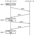
FIG. 6 is a diagram for explaining an entry flow when the meter interface is installed in the embodiment.
図6に示すように、まず、起動スイッチ162でメータインターフェイス150を起動すると、判断部155内の演算部159が起動する。これにより、無線システムを構成するネットワークへ参入するために送受信回路154が起動される(ステップS201)。
As shown in FIG. 6, first, when the meter interface 150 is activated by the activation switch 162, the calculation unit 159 in the determination unit 155 is activated. As a result, the transmission / reception circuit 154 is activated in order to enter the network constituting the wireless system (step S201).
つぎに、演算部159は、予め決められたプロトコルによって生成される第1の参入電文を生成する。そして、送受信回路154、アンテナ151を介して、生成された第1の参入電文をコンセントレータ100へ向けて送信する。このとき、整合調整部153の切り替えスイッチ156は、所定の整合部品を構成する容量素子に接続するように設定される。(ステップS202)。
Next, the calculation unit 159 generates a first entry message generated by a predetermined protocol. Then, the generated first entry message is transmitted to the concentrator 100 via the transmission / reception circuit 154 and the antenna 151. At this time, the changeover switch 156 of the matching adjustment unit 153 is set so as to be connected to a capacitive element constituting a predetermined matching component. (Step S202).
つぎに、送信された第1の参入電文をコンセントレータ100が受信すると、第1の参入電文に対する第1の応答電文を演算部102で生成する。そして、コンセントレータ100は、生成した第1の応答電文をメータインターフェイス150へ送信する(ステップS203)。
Next, when the concentrator 100 receives the transmitted first entry message, the operation unit 102 generates a first response message for the first entry message. Then, the concentrator 100 transmits the generated first response message to the meter interface 150 (step S203).
つぎに、メータインターフェイス150は、送信された第1の応答電文を送受信回路154で受信する。そして、レベル検出部158で、受信信号強度レベルに変換し、演算部159に記憶する。
Next, the meter interface 150 receives the transmitted first response message by the transmission / reception circuit 154. Then, the level detection unit 158 converts the received signal strength level and stores it in the calculation unit 159.
さらに、メータインターフェイス150は、第1の応答電文を受信後に、切り替えスイッチ156を、ステップS202とは異なる整合部品の容量素子へ接続する(ステップS204)。
Further, after receiving the first response message, the meter interface 150 connects the changeover switch 156 to a capacitive element of a matching component different from that in step S202 (step S204).
つぎに、メータインターフェイス150は、演算部159で、第2の参入電文を生成する。そして、送受信回路154、アンテナ151を介して、生成された第2の参入電文をコンセントレータ100へ送信する(ステップS205)。
Next, the meter interface 150 uses the calculation unit 159 to generate a second entry message. Then, the generated second entry message is transmitted to the concentrator 100 via the transmission / reception circuit 154 and the antenna 151 (step S205).
つぎに、送信された第2の参入電文をコンセントレータ100が受信すると、第2の参入電文に対する第2の応答電文をメータインターフェイス150へ送信する(ステップS206)。
Next, when the concentrator 100 receives the transmitted second entry message, the second response message for the second entry message is transmitted to the meter interface 150 (step S206).
つぎに、メータインターフェイス150は、送信された第2の応答電文を送受信回路154で受信する。そして、レベル検出部158で、受信強度信号レベルに変換し、演算部159に記憶する。
Next, the meter interface 150 receives the transmitted second response message by the transmission / reception circuit 154. Then, the level detection unit 158 converts the received intensity signal level and stores it in the calculation unit 159.
つぎに、ステップS204、S206で、演算部159に記憶した受信信号強度レベルを比較して、大小を判断する。そして、受信信号強度レベルレベルが大きい整合部品側へ、切り替えスイッチ156を切り替えて設定する(ステップS207)。
Next, in steps S204 and S206, the received signal strength levels stored in the calculation unit 159 are compared to determine the magnitude. Then, the selector switch 156 is switched and set to the matching component side where the received signal strength level is large (step S207).
そして、以降は、実施の形態1と同様の動作を実行する。
Thereafter, the same operation as in the first embodiment is executed.
以上のように、本実施の形態の切り替えスイッチ156の切り替え手順が実行される。
As described above, the switching procedure of the changeover switch 156 of the present embodiment is executed.
つまり、本実施の形態では、メータインターフェイスを設置し、コンセントレータなどの他の無線装置とネットワーク接続する際、整合部品を切り替え、複数回受信信号強度レベルを検出する。そして、受信信号強度レベルが大きい方の整合部品を設定する。これにより、メータインターフェイスの設置環境に影響されずに、ロバストな通信ができる。つまり、メータインターフェイスを画一的なルールで設置できる。その結果、メータインターフェイスの設置作業の簡易化が図れる。
That is, in this embodiment, when a meter interface is installed and connected to another wireless device such as a concentrator through a network, matching components are switched and a received signal strength level is detected a plurality of times. Then, the matching component having the larger received signal strength level is set. Thereby, robust communication can be performed without being affected by the installation environment of the meter interface. In other words, the meter interface can be installed with uniform rules. As a result, the installation work of the meter interface can be simplified.
なお、上述した複数回の受信信号強度レベルを受信する方法は、一般的にプロトコルに依存する。そのため、上記で示した切り替え方法は一例に過ぎない。例えば、上位の端末が、定期的にビーコンを送信するネットワークなどの場合、起動スイッチでメータインターフェイスを起動後、ビーコンの連続受信動作に移行する。このとき、複数のビーコンを、複数の整合回路から整合定数を切り替えながら受信する。そして、送受信回路のレベル検出部で受信した受信信号強度レベルを比較して、最も受信レベルの大きい整合回路を選択する構成としてもよい。
Note that the method of receiving the received signal strength level at a plurality of times described above generally depends on the protocol. Therefore, the switching method shown above is only an example. For example, in the case of a network or the like in which a host terminal periodically transmits a beacon, the meter interface is activated by the activation switch, and then the operation proceeds to a continuous beacon reception operation. At this time, a plurality of beacons are received from a plurality of matching circuits while switching matching constants. The received signal strength level received by the level detection unit of the transmission / reception circuit may be compared to select a matching circuit having the highest reception level.
また、中継機を含む無線ネットワークシステムにおいては、受信信号強度レベルだけでなく、中継段数の情報を使って判断する構成としてもよい。この場合、閾値以上であれば、受信信号強度レベルではなく、中継段数の情報を優先して判断し、例えば中継段数が最小となるルートに決める。一方、閾値以下の場合、受信信号強度レベルを優先して制御する。これにより、消費電流の抑制と、高い通信応答性を両立させることができる。
In addition, in a wireless network system including a repeater, a determination may be made using not only the received signal strength level but also information on the number of relay stages. In this case, if it is equal to or greater than the threshold value, the information on the number of relay stages is given priority over the received signal strength level, and for example, the route with the minimum number of relay stages is determined. On the other hand, when the value is equal to or less than the threshold, the received signal strength level is controlled with priority. Thereby, suppression of consumption current and high communication responsiveness can be made compatible.
(実施の形態3)
以下に、本発明の実施の形態3における無線装置の構成について、図7を用いて説明する。具体的には、メータインターフェイス内の切り替えスイッチ156の切り替え方法について、説明する。 (Embodiment 3)
The configuration of the radio apparatus according toEmbodiment 3 of the present invention will be described below using FIG. Specifically, a method for switching the changeover switch 156 in the meter interface will be described.
以下に、本発明の実施の形態3における無線装置の構成について、図7を用いて説明する。具体的には、メータインターフェイス内の切り替えスイッチ156の切り替え方法について、説明する。 (Embodiment 3)
The configuration of the radio apparatus according to
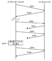
図7は、本発明の実施の形態3におけるメータインターフェイスとコンセントレータ間の通信フローを説明する図である。
FIG. 7 is a diagram for explaining a communication flow between the meter interface and the concentrator in the third embodiment of the present invention.
なお、以下では、実施の形態1および実施の形態2と異なる部分のみについて、詳細に説明する。
In the following, only parts different from the first embodiment and the second embodiment will be described in detail.
図7に示すように、本実施の形態は、メータインターフェイスとコンセントレータ間の通信に異常が発生した場合の処理動作を備える点で、実施の形態1、2とは異なる。他の構成や動作は、実施の形態1、2と同様であるので、説明を省略する。
As shown in FIG. 7, the present embodiment is different from the first and second embodiments in that it includes a processing operation when an abnormality occurs in communication between the meter interface and the concentrator. Other configurations and operations are the same as those in the first and second embodiments, and thus description thereof is omitted.
具体的には、図7に示すように、メータインターフェイス150とコンセントレータ100間で定期的に実施される通信や、メータ161やメータインターフェイス150に異常が発生した際の不適切な通信時に適応される。なお、定期的な通信とは、例えばメータ161から取得した検針値をコンセントレータ100、サーバーへ上げる通信である。また、メータ161やメータインターフェイス150の異常とは、例えば電池電圧低下アラーム、ハードウェアエラーや不正使用などである。
Specifically, as shown in FIG. 7, it is applied to communication performed periodically between the meter interface 150 and the concentrator 100 or inappropriate communication when an abnormality occurs in the meter 161 or the meter interface 150. . Note that the periodic communication is communication for raising the meter reading value acquired from the meter 161 to the concentrator 100 and the server, for example. Moreover, the abnormality of the meter 161 or the meter interface 150 is, for example, a battery voltage drop alarm, a hardware error, or an unauthorized use.
以下に、本実施の形態の無線装置のメータインターフェイスとコンセントレータ間での通信動作について、図7を参照しながら説明する。
Hereinafter, a communication operation between the meter interface and the concentrator of the wireless device according to the present embodiment will be described with reference to FIG.
図7に示すように、まず、メータインターフェイス150は、所定のプロトコルに従って、演算部159で電文を生成する。そして、送受信回路154、アンテナ151を介して、生成した電文を送信する(ステップS301)。
As shown in FIG. 7, first, the meter interface 150 generates a message by the calculation unit 159 according to a predetermined protocol. And the produced | generated message | telegram is transmitted via the transmission / reception circuit 154 and the antenna 151 (step S301).
つぎに、送信された電文をコンセントレータ100が受信すると、コンセントレータ100は、メータインターフェイス150に対して、応答電文あるいはACK信号を送信する(ステップS302)。
Next, when the concentrator 100 receives the transmitted message, the concentrator 100 transmits a response message or an ACK signal to the meter interface 150 (step S302).
このとき、ステップS301、S302の通信が成立すれば、メータインターフェイス150は通信が成功したと判断できる。
At this time, if the communication in steps S301 and S302 is established, the meter interface 150 can determine that the communication is successful.
以下に、メータインターフェイス150とコンセントレータ100間の通信が不通となった際の制御フローについて、説明する。
Hereinafter, a control flow when communication between the meter interface 150 and the concentrator 100 is interrupted will be described.
まず、上記と同様に、メータインターフェイス150からコンセントレータ100へ電文を送信する(ステップS303)。このとき、コンセントレータ100からの、送信した電文に対する応答電文がメータインターフェイス150に届かない場合(ステップS304)、メータインターフェイス150は所定の時間が経過した後、所定の回数、電文の再送を行う(ステップS305)。
First, similarly to the above, a telegram is transmitted from the meter interface 150 to the concentrator 100 (step S303). At this time, when the response message for the transmitted message from the concentrator 100 does not reach the meter interface 150 (step S304), the meter interface 150 retransmits the message a predetermined number of times after a predetermined time has elapsed (step S304). S305).
そして、電文を再送しても、コンセントレータ100からの応答電文を受信できない場合、整合調整部153内の切り替えスイッチ156を切り替える。このとき、ステップS303からステップS305において接続していた整合部品とは、別の整合部品に接続するように切り替えスイッチ156を切り替え制御する(ステップS307)。
If the response message from the concentrator 100 cannot be received even if the message is retransmitted, the changeover switch 156 in the matching adjustment unit 153 is switched. At this time, the changeover switch 156 is controlled so as to be connected to another matching part from the matching part connected in steps S303 to S305 (step S307).
つぎに、メータインターフェイス150は、再度、生成した電文を、コンセントレータ100へ送信する(ステップS308)。
Next, the meter interface 150 transmits the generated message again to the concentrator 100 (step S308).
これにより、メータインターフェイス150とコンセントレータ100間の通信が成立する可能性がある(ステップS309)。
This may establish communication between the meter interface 150 and the concentrator 100 (step S309).
つまり、本実施の形態のように、メータインターフェイス150の複数の整合部品157を適宜変更することにより、存在しないコンセントレータとの通信条件を変更することができる。そのため、メータインターフェイスを設置後に、環境条件が変化し、通信ができなくなった場合にも対応することができる。これにより、通信のロバスト性や、メータインターフェイスの設置位置の変更などを行う必要がない。その結果、メンテナンス性の向上、ネットワークの運用コストを抑制できる。
That is, the communication conditions with the non-existing concentrator can be changed by appropriately changing the plurality of matching parts 157 of the meter interface 150 as in the present embodiment. For this reason, after the meter interface is installed, it is possible to cope with the case where the environmental conditions change and communication becomes impossible. Thereby, there is no need to perform communication robustness or change the installation position of the meter interface. As a result, maintainability can be improved and network operation costs can be suppressed.
また、本実施の形態では、定期的に受信信号強度レベルを取得し、設置時や、前回通信との比較を行うことができる。つまり、受信信号強度レベルが大きく劣化している場合、切り替えスイッチ156を切り替え、判断部155で比較し最適な整合部品へ設定変更する。これにより、通信のロバスト性を向上できる。さらに、アンテナを複数使用してダイバーシティを実現する方法と比べても、部品コストや小型化の面で優位となる。
Further, in this embodiment, the received signal strength level can be periodically acquired and compared with the previous communication at the time of installation. That is, when the received signal strength level is greatly deteriorated, the changeover switch 156 is switched, and the determination unit 155 compares and changes the setting to the optimum matching component. Thereby, the robustness of communication can be improved. Furthermore, it is advantageous in terms of component cost and miniaturization as compared with a method of realizing diversity by using a plurality of antennas.
以上で説明したように、本発明の無線装置は、無線信号を送信・受信するアンテナと、送受信回路と、アンテナと送受信回路との整合、位相調整機能を有する整合部を有する。アンテナの整合状態を変更するために、切り替えスイッチと複数の整合部品で構成される整合調整部と、アンテナを介して受信した無線信号の受信レベルを検出するレベル検出部を有する。さらに、レベル検出部から出力されるレベルに応じて、整合調整部の切り替えスイッチを切り替える判断部を有してもよい。
As described above, the wireless device of the present invention includes an antenna that transmits and receives wireless signals, a transmission / reception circuit, a matching unit that has a function of matching between the antenna and the transmission / reception circuit, and a phase adjustment function. In order to change the matching state of the antenna, a matching adjustment unit including a changeover switch and a plurality of matching parts, and a level detection unit that detects a reception level of a radio signal received via the antenna are provided. Furthermore, a determination unit that switches a changeover switch of the matching adjustment unit according to the level output from the level detection unit may be provided.
これにより、無線装置の設置環境の影響を抑制して、通信のロバスト性を確保するとともに、消費電流を抑制できる。
This makes it possible to suppress the influence of the installation environment of the wireless device, ensure communication robustness, and suppress current consumption.
また、本発明の無線装置は、整合部は容量素子とインダクタのみで構成し、整合調整部内は、複数の整合部品は容量素子のみで構成してもよい。
Further, in the wireless device of the present invention, the matching unit may be composed of only a capacitive element and an inductor, and a plurality of matching parts may be composed of only the capacitive element in the matching adjustment unit.
これにより、無線装置の小型化およびコストを抑制できる。さらに、無線通信のロバスト性も確保できる。
This can reduce the size and cost of the wireless device. Furthermore, the robustness of wireless communication can be ensured.
また、本発明の無線装置の判断部は、整合調整部内の切り替えスイッチを切り替え、レベル検出部からの出力される受信レベルが高い切り替え状態を選択するように制御してもよい。
Also, the determination unit of the wireless device of the present invention may perform control so as to switch a changeover switch in the matching adjustment unit and select a switching state in which the reception level output from the level detection unit is high.
これにより、無線装置の設置環境の影響を抑制して、通信のロバスト性を確保するとともに、消費電流を抑制できる。
This makes it possible to suppress the influence of the installation environment of the wireless device, ensure communication robustness, and suppress current consumption.
また、本発明の無線装置の判断部は、無線装置を設置する際に、整合調整部内の切り替えスイッチを少なくとも1回以上切り替え、レベル検出部から出力される受信レベルが高い切り替え状態を選択し、以後の通信を行うように構成してもよい。
Further, the determination unit of the wireless device of the present invention switches the changeover switch in the matching adjustment unit at least once when installing the wireless device, and selects a switching state in which the reception level output from the level detection unit is high, You may comprise so that subsequent communication may be performed.
これにより、無線装置の設置環境の影響を抑制し、通信ロバスト性を確保するとともに、消費電流を抑制できる。
This makes it possible to suppress the influence of the installation environment of the wireless device, ensure communication robustness, and suppress current consumption.
また、本発明の無線装置の判断部は、他の無線装置と通信した後、通信ができなくなった場合、整合調整部内の切り替えスイッチを切り替えて、再度通信を行う構成としてもよい。
In addition, the determination unit of the wireless device of the present invention may be configured to perform communication again by switching the changeover switch in the matching adjustment unit when communication becomes impossible after communication with another wireless device.
これにより、無線装置が設置された後に、周囲環境が変更しても無線装置のアンテナ性能を最適化できる。その結果、通信ロバスト性を確保するとともに、消費電流の抑制を図ることができる。
This allows the antenna performance of the wireless device to be optimized even if the surrounding environment changes after the wireless device is installed. As a result, communication robustness can be ensured and current consumption can be suppressed.
また、本発明の無線装置は、起動スイッチを、さらに備え、判断部は、起動スイッチの起動後に、整合調整部の切り替えスイッチの切り替え動作を行ってもよい。これにより、消費電力を抑制して、長寿命化を図ることができる。
The wireless device of the present invention may further include an activation switch, and the determination unit may perform the switching operation of the changeover switch of the matching adjustment unit after the activation switch is activated. Thereby, power consumption can be suppressed and the life can be extended.
本発明の無線装置は、設置時にアンテナの性能を最適な状態で設置することができる。そのため、固定して使用される無線装置に有用である。
The wireless device of the present invention can be installed in an optimum state of antenna performance at the time of installation. Therefore, it is useful for a wireless device used in a fixed manner.
100 コンセントレータ
101 長距離無線部
102,159 演算部
103 短距離無線部
104 基準クロック生成部
105 レベル演算部
106 設置情報記憶部
150 メータインターフェイス
151 アンテナ
152 整合部
153 整合調整部
154 送受信回路
155 判断部
156 切り替えスイッチ
157 複数の整合部品
157a,157b 整合部品
158 レベル検出部
160 カウントインターフェイス部
161 メータ
162 起動スイッチ DESCRIPTION OFSYMBOLS 100 Concentrator 101 Long distance radio | wireless part 102,159 Calculation part 103 Short distance radio | wireless part 104 Reference clock generation part 105 Level calculation part 106 Installation information storage part 150 Meter interface 151 Antenna 152 Matching part 153 Matching adjustment part 154 Transmission / reception circuit 155 Judgment part 156 Changeover switch 157 Multiple matching parts 157a, 157b Matching parts 158 Level detection part 160 Count interface part 161 Meter 162 Start switch
101 長距離無線部
102,159 演算部
103 短距離無線部
104 基準クロック生成部
105 レベル演算部
106 設置情報記憶部
150 メータインターフェイス
151 アンテナ
152 整合部
153 整合調整部
154 送受信回路
155 判断部
156 切り替えスイッチ
157 複数の整合部品
157a,157b 整合部品
158 レベル検出部
160 カウントインターフェイス部
161 メータ
162 起動スイッチ DESCRIPTION OF
Claims (6)
- 無線信号を送信・受信するアンテナと、
送受信回路と、
前記アンテナと前記送受信回路との整合、位相調整機能を有する整合部と、
前記アンテナの整合状態を変更するために、切り替えスイッチと複数の整合部品で構成される整合調整部と、
前記アンテナを介して受信した前記無線信号の受信レベルを検出するレベル検出部と、
前記レベル検出部から出力されるレベルに応じて、前記整合調整部の前記切り替えスイッチを切り替える判断部と、を有する無線装置。 An antenna for transmitting and receiving radio signals;
A transceiver circuit;
Matching between the antenna and the transmission / reception circuit, a matching unit having a phase adjustment function;
In order to change the matching state of the antenna, a matching adjustment unit including a changeover switch and a plurality of matching parts;
A level detection unit for detecting a reception level of the radio signal received via the antenna;
And a determination unit that switches the changeover switch of the matching adjustment unit according to a level output from the level detection unit. - 前記整合部は容量素子とインダクタのみで構成し、
前記整合調整部内の、前記複数の整合部品は容量素子のみで構成する請求項1に記載の無線装置。 The matching part is composed only of a capacitive element and an inductor,
The wireless device according to claim 1, wherein the plurality of matching components in the matching adjustment unit are configured only by capacitive elements. - 前記判断部は、前記整合調整部内の前記切り替えスイッチを切り替え、
前記レベル検出部からの出力される受信レベルが高い切り替え状態を選択するように制御する請求項1に記載の無線装置。 The determination unit switches the changeover switch in the matching adjustment unit,
The radio apparatus according to claim 1, wherein control is performed so as to select a switching state in which a reception level output from the level detection unit is high. - 前記判断部は、
無線装置を設置する際に、前記整合調整部内の前記切り替えスイッチを少なくとも1回以上切り替え、前記レベル検出部から出力される受信レベルが高い切り替え状態を選択し、以後の通信を行う請求項1に記載の無線装置。 The determination unit
The apparatus according to claim 1, wherein when the wireless device is installed, the changeover switch in the matching adjustment unit is switched at least once, a switching state with a high reception level output from the level detection unit is selected, and subsequent communication is performed. The wireless device described. - 前記判断部は、
他の無線装置と通信した後、通信ができなくなった場合、前記整合調整部内の前記切り替えスイッチを切り替えて、再度通信を行う請求項1に記載の無線装置。 The determination unit
The wireless device according to claim 1, wherein, when communication becomes impossible after communication with another wireless device, communication is performed again by switching the changeover switch in the matching adjustment unit. - 起動スイッチを、さらに備え、
前記判断部は、前記起動スイッチの起動後に、前記整合調整部の前記切り替えスイッチの切り替え動作を行う請求項1に記載の無線装置。 A start switch,
The wireless device according to claim 1, wherein the determination unit performs a switching operation of the changeover switch of the matching adjustment unit after the activation switch is activated.
Priority Applications (2)
| Application Number | Priority Date | Filing Date | Title |
|---|---|---|---|
| JP2016539814A JPWO2016021105A1 (en) | 2014-08-07 | 2015-06-24 | Wireless device |
| EP15830621.7A EP3179635A4 (en) | 2014-08-07 | 2015-06-24 | Radio apparatus |
Applications Claiming Priority (2)
| Application Number | Priority Date | Filing Date | Title |
|---|---|---|---|
| JP2014-161117 | 2014-08-07 | ||
| JP2014161117 | 2014-08-07 |
Publications (1)
| Publication Number | Publication Date |
|---|---|
| WO2016021105A1 true WO2016021105A1 (en) | 2016-02-11 |
Family
ID=55263405
Family Applications (1)
| Application Number | Title | Priority Date | Filing Date |
|---|---|---|---|
| PCT/JP2015/003161 WO2016021105A1 (en) | 2014-08-07 | 2015-06-24 | Radio apparatus |
Country Status (3)
| Country | Link |
|---|---|
| EP (1) | EP3179635A4 (en) |
| JP (1) | JPWO2016021105A1 (en) |
| WO (1) | WO2016021105A1 (en) |
Cited By (1)
| Publication number | Priority date | Publication date | Assignee | Title |
|---|---|---|---|---|
| EP3285403A1 (en) * | 2016-08-18 | 2018-02-21 | Diehl Metering S.A.S. | Method and device for improving the antenna adjustment of a smart meter |
Families Citing this family (1)
| Publication number | Priority date | Publication date | Assignee | Title |
|---|---|---|---|---|
| EP4051991B1 (en) * | 2021-01-19 | 2023-05-31 | VEGA Grieshaber KG | Arrangement and method for selecting a sensor-rf module property |
Citations (3)
| Publication number | Priority date | Publication date | Assignee | Title |
|---|---|---|---|---|
| JP2006270366A (en) * | 2005-03-23 | 2006-10-05 | Sony Ericsson Mobilecommunications Japan Inc | Mobile wireless communication terminal and its control method |
| JP2006325163A (en) * | 2005-05-20 | 2006-11-30 | Toyota Industries Corp | Wide band transmitter/receiver |
| JP2011009862A (en) * | 2009-06-23 | 2011-01-13 | Fujitsu Ltd | Wireless communication apparatus and impedance control method |
Family Cites Families (2)
| Publication number | Priority date | Publication date | Assignee | Title |
|---|---|---|---|---|
| CN102752007B (en) * | 2012-06-28 | 2015-02-11 | 惠州Tcl移动通信有限公司 | Mobile terminal for automatically adjusting antenna matching and control method thereof |
| US9374113B2 (en) * | 2012-12-21 | 2016-06-21 | Blackberry Limited | Method and apparatus for adjusting the timing of radio antenna tuning |
-
2015
- 2015-06-24 WO PCT/JP2015/003161 patent/WO2016021105A1/en active Application Filing
- 2015-06-24 EP EP15830621.7A patent/EP3179635A4/en not_active Withdrawn
- 2015-06-24 JP JP2016539814A patent/JPWO2016021105A1/en active Pending
Patent Citations (3)
| Publication number | Priority date | Publication date | Assignee | Title |
|---|---|---|---|---|
| JP2006270366A (en) * | 2005-03-23 | 2006-10-05 | Sony Ericsson Mobilecommunications Japan Inc | Mobile wireless communication terminal and its control method |
| JP2006325163A (en) * | 2005-05-20 | 2006-11-30 | Toyota Industries Corp | Wide band transmitter/receiver |
| JP2011009862A (en) * | 2009-06-23 | 2011-01-13 | Fujitsu Ltd | Wireless communication apparatus and impedance control method |
Non-Patent Citations (1)
| Title |
|---|
| See also references of EP3179635A4 * |
Cited By (1)
| Publication number | Priority date | Publication date | Assignee | Title |
|---|---|---|---|---|
| EP3285403A1 (en) * | 2016-08-18 | 2018-02-21 | Diehl Metering S.A.S. | Method and device for improving the antenna adjustment of a smart meter |
Also Published As
| Publication number | Publication date |
|---|---|
| JPWO2016021105A1 (en) | 2017-05-18 |
| EP3179635A4 (en) | 2018-04-11 |
| EP3179635A1 (en) | 2017-06-14 |
Similar Documents
| Publication | Publication Date | Title |
|---|---|---|
| US11706858B2 (en) | Occupancy sensing lighting control system | |
| JP6087556B2 (en) | Wireless communication terminal, wireless communication device, wireless communication system, frequency band switching method | |
| US9831705B2 (en) | Resolving communcations in a wireless power system with co-located transmitters | |
| JP5877385B2 (en) | Wireless communication system | |
| JP5849988B2 (en) | Field wireless relay device | |
| KR102250248B1 (en) | Wireless charging system using ultra wide band | |
| US9185645B2 (en) | Mobile communication system, method of controlling the same, and radio base station apparatus | |
| WO2016021105A1 (en) | Radio apparatus | |
| JP2005039649A (en) | Base station apparatus and wireless radio | |
| JP2008159038A (en) | Radio sensor device | |
| KR20110020677A (en) | Wireless parking detector using multiple antennas and its detecting methods | |
| JP2021035257A (en) | Electronic device and method | |
| JP2007306087A (en) | Radio communication system | |
| JP5796179B2 (en) | Communication device | |
| JP2002100917A (en) | Indoor antenna system | |
| KR101615693B1 (en) | Method for controlling oscillation in small repeater and repeater device using the same | |
| WO2019087804A1 (en) | Measurement method, measurement program, and measurement device | |
| WO2023170774A1 (en) | Radio wave control system, control device, control method, and non-transitory computer readable medium | |
| WO2011039938A1 (en) | Wireless device, wireless apparatus using same, and wireless system | |
| JP2006246338A (en) | Mobile wireless communication terminal | |
| US20230369899A1 (en) | Integrated wireless-power-transmission platform designed to operate in multiple bands, and multi-band antennas for use therewith | |
| JP2010233011A (en) | Wireless sensor terminal and wireless sensor network system employing the same | |
| JP6221050B2 (en) | Wireless communication system, wireless terminal, and communication method | |
| JP4847548B2 (en) | Base station apparatus and radio communication system | |
| JP2005303342A (en) | Wireless access relay apparatus |
Legal Events
| Date | Code | Title | Description |
|---|---|---|---|
| 121 | Ep: the epo has been informed by wipo that ep was designated in this application |
Ref document number: 15830621 Country of ref document: EP Kind code of ref document: A1 |
|
| ENP | Entry into the national phase |
Ref document number: 2016539814 Country of ref document: JP Kind code of ref document: A |
|
| REEP | Request for entry into the european phase |
Ref document number: 2015830621 Country of ref document: EP |
|
| NENP | Non-entry into the national phase |
Ref country code: DE |