WO2016017824A1 - Intermediate film for laminated glass, and laminated glass - Google Patents
Intermediate film for laminated glass, and laminated glass Download PDFInfo
- Publication number
- WO2016017824A1 WO2016017824A1 PCT/JP2015/072003 JP2015072003W WO2016017824A1 WO 2016017824 A1 WO2016017824 A1 WO 2016017824A1 JP 2015072003 W JP2015072003 W JP 2015072003W WO 2016017824 A1 WO2016017824 A1 WO 2016017824A1
- Authority
- WO
- WIPO (PCT)
- Prior art keywords
- laminated glass
- interlayer film
- light emitting
- emitting layer
- mol
- Prior art date
Links
Images

Classifications
-
- B—PERFORMING OPERATIONS; TRANSPORTING
- B32—LAYERED PRODUCTS
- B32B—LAYERED PRODUCTS, i.e. PRODUCTS BUILT-UP OF STRATA OF FLAT OR NON-FLAT, e.g. CELLULAR OR HONEYCOMB, FORM
- B32B17/00—Layered products essentially comprising sheet glass, or glass, slag, or like fibres
- B32B17/06—Layered products essentially comprising sheet glass, or glass, slag, or like fibres comprising glass as the main or only constituent of a layer, next to another layer of a specific material
- B32B17/10—Layered products essentially comprising sheet glass, or glass, slag, or like fibres comprising glass as the main or only constituent of a layer, next to another layer of a specific material of synthetic resin
- B32B17/10005—Layered products essentially comprising sheet glass, or glass, slag, or like fibres comprising glass as the main or only constituent of a layer, next to another layer of a specific material of synthetic resin laminated safety glass or glazing
- B32B17/1055—Layered products essentially comprising sheet glass, or glass, slag, or like fibres comprising glass as the main or only constituent of a layer, next to another layer of a specific material of synthetic resin laminated safety glass or glazing characterized by the resin layer, i.e. interlayer
- B32B17/10559—Shape of the cross-section
- B32B17/10568—Shape of the cross-section varying in thickness
-
- B—PERFORMING OPERATIONS; TRANSPORTING
- B32—LAYERED PRODUCTS
- B32B—LAYERED PRODUCTS, i.e. PRODUCTS BUILT-UP OF STRATA OF FLAT OR NON-FLAT, e.g. CELLULAR OR HONEYCOMB, FORM
- B32B17/00—Layered products essentially comprising sheet glass, or glass, slag, or like fibres
- B32B17/06—Layered products essentially comprising sheet glass, or glass, slag, or like fibres comprising glass as the main or only constituent of a layer, next to another layer of a specific material
- B32B17/10—Layered products essentially comprising sheet glass, or glass, slag, or like fibres comprising glass as the main or only constituent of a layer, next to another layer of a specific material of synthetic resin
- B32B17/10005—Layered products essentially comprising sheet glass, or glass, slag, or like fibres comprising glass as the main or only constituent of a layer, next to another layer of a specific material of synthetic resin laminated safety glass or glazing
- B32B17/1055—Layered products essentially comprising sheet glass, or glass, slag, or like fibres comprising glass as the main or only constituent of a layer, next to another layer of a specific material of synthetic resin laminated safety glass or glazing characterized by the resin layer, i.e. interlayer
- B32B17/10651—Layered products essentially comprising sheet glass, or glass, slag, or like fibres comprising glass as the main or only constituent of a layer, next to another layer of a specific material of synthetic resin laminated safety glass or glazing characterized by the resin layer, i.e. interlayer comprising colorants, e.g. dyes or pigments
- B32B17/10669—Luminescent agents
-
- B—PERFORMING OPERATIONS; TRANSPORTING
- B32—LAYERED PRODUCTS
- B32B—LAYERED PRODUCTS, i.e. PRODUCTS BUILT-UP OF STRATA OF FLAT OR NON-FLAT, e.g. CELLULAR OR HONEYCOMB, FORM
- B32B17/00—Layered products essentially comprising sheet glass, or glass, slag, or like fibres
- B32B17/06—Layered products essentially comprising sheet glass, or glass, slag, or like fibres comprising glass as the main or only constituent of a layer, next to another layer of a specific material
- B32B17/10—Layered products essentially comprising sheet glass, or glass, slag, or like fibres comprising glass as the main or only constituent of a layer, next to another layer of a specific material of synthetic resin
- B32B17/10005—Layered products essentially comprising sheet glass, or glass, slag, or like fibres comprising glass as the main or only constituent of a layer, next to another layer of a specific material of synthetic resin laminated safety glass or glazing
- B32B17/1055—Layered products essentially comprising sheet glass, or glass, slag, or like fibres comprising glass as the main or only constituent of a layer, next to another layer of a specific material of synthetic resin laminated safety glass or glazing characterized by the resin layer, i.e. interlayer
- B32B17/10688—Adjustment of the adherence to the glass layers
-
- B—PERFORMING OPERATIONS; TRANSPORTING
- B32—LAYERED PRODUCTS
- B32B—LAYERED PRODUCTS, i.e. PRODUCTS BUILT-UP OF STRATA OF FLAT OR NON-FLAT, e.g. CELLULAR OR HONEYCOMB, FORM
- B32B17/00—Layered products essentially comprising sheet glass, or glass, slag, or like fibres
- B32B17/06—Layered products essentially comprising sheet glass, or glass, slag, or like fibres comprising glass as the main or only constituent of a layer, next to another layer of a specific material
- B32B17/10—Layered products essentially comprising sheet glass, or glass, slag, or like fibres comprising glass as the main or only constituent of a layer, next to another layer of a specific material of synthetic resin
- B32B17/10005—Layered products essentially comprising sheet glass, or glass, slag, or like fibres comprising glass as the main or only constituent of a layer, next to another layer of a specific material of synthetic resin laminated safety glass or glazing
- B32B17/1055—Layered products essentially comprising sheet glass, or glass, slag, or like fibres comprising glass as the main or only constituent of a layer, next to another layer of a specific material of synthetic resin laminated safety glass or glazing characterized by the resin layer, i.e. interlayer
- B32B17/10761—Layered products essentially comprising sheet glass, or glass, slag, or like fibres comprising glass as the main or only constituent of a layer, next to another layer of a specific material of synthetic resin laminated safety glass or glazing characterized by the resin layer, i.e. interlayer containing vinyl acetal
-
- B—PERFORMING OPERATIONS; TRANSPORTING
- B32—LAYERED PRODUCTS
- B32B—LAYERED PRODUCTS, i.e. PRODUCTS BUILT-UP OF STRATA OF FLAT OR NON-FLAT, e.g. CELLULAR OR HONEYCOMB, FORM
- B32B27/00—Layered products comprising a layer of synthetic resin
- B32B27/18—Layered products comprising a layer of synthetic resin characterised by the use of special additives
-
- C—CHEMISTRY; METALLURGY
- C03—GLASS; MINERAL OR SLAG WOOL
- C03C—CHEMICAL COMPOSITION OF GLASSES, GLAZES OR VITREOUS ENAMELS; SURFACE TREATMENT OF GLASS; SURFACE TREATMENT OF FIBRES OR FILAMENTS MADE FROM GLASS, MINERALS OR SLAGS; JOINING GLASS TO GLASS OR OTHER MATERIALS
- C03C27/00—Joining pieces of glass to pieces of other inorganic material; Joining glass to glass other than by fusing
- C03C27/06—Joining glass to glass by processes other than fusing
- C03C27/10—Joining glass to glass by processes other than fusing with the aid of adhesive specially adapted for that purpose
-
- B—PERFORMING OPERATIONS; TRANSPORTING
- B32—LAYERED PRODUCTS
- B32B—LAYERED PRODUCTS, i.e. PRODUCTS BUILT-UP OF STRATA OF FLAT OR NON-FLAT, e.g. CELLULAR OR HONEYCOMB, FORM
- B32B2250/00—Layers arrangement
- B32B2250/02—2 layers
-
- B—PERFORMING OPERATIONS; TRANSPORTING
- B32—LAYERED PRODUCTS
- B32B—LAYERED PRODUCTS, i.e. PRODUCTS BUILT-UP OF STRATA OF FLAT OR NON-FLAT, e.g. CELLULAR OR HONEYCOMB, FORM
- B32B2307/00—Properties of the layers or laminate
- B32B2307/40—Properties of the layers or laminate having particular optical properties
- B32B2307/412—Transparent
-
- B—PERFORMING OPERATIONS; TRANSPORTING
- B32—LAYERED PRODUCTS
- B32B—LAYERED PRODUCTS, i.e. PRODUCTS BUILT-UP OF STRATA OF FLAT OR NON-FLAT, e.g. CELLULAR OR HONEYCOMB, FORM
- B32B2329/00—Polyvinylalcohols, polyvinylethers, polyvinylaldehydes, polyvinylketones or polyvinylketals
- B32B2329/06—PVB, i.e. polyinylbutyral
-
- B—PERFORMING OPERATIONS; TRANSPORTING
- B32—LAYERED PRODUCTS
- B32B—LAYERED PRODUCTS, i.e. PRODUCTS BUILT-UP OF STRATA OF FLAT OR NON-FLAT, e.g. CELLULAR OR HONEYCOMB, FORM
- B32B2331/00—Polyvinylesters
- B32B2331/04—Polymers of vinyl acetate, e.g. PVA
-
- C—CHEMISTRY; METALLURGY
- C08—ORGANIC MACROMOLECULAR COMPOUNDS; THEIR PREPARATION OR CHEMICAL WORKING-UP; COMPOSITIONS BASED THEREON
- C08K—Use of inorganic or non-macromolecular organic substances as compounding ingredients
- C08K5/00—Use of organic ingredients
- C08K5/56—Organo-metallic compounds, i.e. organic compounds containing a metal-to-carbon bond
Definitions
- the present invention relates to an interlayer film for laminated glass that can display an image with high emission intensity by irradiating light and has excellent durability, and a laminated glass including the interlayer film for laminated glass.
- Laminated glass is safe because it does not scatter glass fragments even if it is damaged by an external impact, so it can be used as a windshield, side glass, rear glass for vehicles such as automobiles, and window glass for aircraft, buildings, etc. Widely used.
- the laminated glass include a laminated glass obtained by integrating an interlayer film for laminated glass including a liquid plasticizer and a polyvinyl acetal resin between at least a pair of glasses.
- HUD head-up display
- Patent Document 2 the applicant of the present application is for a laminated glass having a light emitting layer containing a binder resin and at least one light emitting material selected from the group consisting of a light emitting particle, a light emitting pigment, and a light emitting dye.
- An interlayer film has been disclosed.
- Luminescent materials such as luminescent particles, luminescent pigments, and luminescent dyes have the property of emitting light when irradiated with light of a specific wavelength.
- the present invention can display an image with high emission intensity by irradiating light, and has excellent durability, and a laminated glass including the laminated glass interlayer film.
- the object is to provide glass.
- the present invention is an interlayer film for laminated glass having a light emitting layer containing a polyvinyl acetal resin and a lanthanoid complex as light emitting particles, wherein the total content of nitric acid component and carbonic acid component contained in the light emitting layer is 100 ppm. It is the following interlayer film for laminated glass. The present invention is described in detail below.
- the inventors of the present invention have studied the cause of the decrease in durability when an interlayer film for laminated glass is produced using a lanthanoid complex. As a result, it has been found that the cause is a nitric acid component or a carbonic acid component contained in the interlayer film for laminated glass.
- the interlayer film for laminated glass contains a nitric acid component and a carbonic acid component derived from raw materials such as a neutralizing agent used during the production of the thermoplastic resin. It was considered that when a lanthanoid complex was blended with such an interlayer film for laminated glass, the nitric acid component or carbonic acid component interacted with the lanthanoid complex, and the durability of the lanthanoid complex was lowered.
- the inventors have determined that the total content of the nitric acid component and the carbonic acid component contained in the interlayer film for laminated glass is not more than a certain level, so that even when a lanthanoid complex is used, it is durable. As a result, the inventors have found that it is possible to prevent deterioration of the properties, and have completed the present invention.
- the interlayer film for laminated glass of the present invention has a light emitting layer containing a thermoplastic resin and a lanthanoid complex.
- a thermoplastic resin containing the lanthanoid complex, an image with high contrast can be displayed by irradiating the light emitting layer with light.
- thermoplastic resin is not particularly limited.
- polyvinyl acetal resin ethylene-vinyl acetate copolymer resin, ethylene-acrylic copolymer resin, polyurethane resin, polyurethane resin containing sulfur element, polyvinyl alcohol resin, vinyl chloride.
- resins and polyethylene terephthalate resins include resins and polyethylene terephthalate resins.
- a polyvinyl acetal resin is preferable.
- the polyvinyl acetal is not particularly limited as long as it is a polyvinyl acetal obtained by acetalizing polyvinyl alcohol with an aldehyde, but polyvinyl butyral is preferable. Moreover, you may use together 2 or more types of polyvinyl acetal as needed.
- the preferable lower limit of the degree of acetalization of the polyvinyl acetal is 40 mol%, the preferable upper limit is 85 mol%, the more preferable lower limit is 60 mol%, and the more preferable upper limit is 75 mol%.
- the polyvinyl acetal has a preferred lower limit of the hydroxyl group content of 15 mol% and a preferred upper limit of 35 mol%.
- the hydroxyl group amount is 15 mol% or more, the interlayer film for laminated glass can be easily molded.
- the amount of hydroxyl group is 35 mol% or less, handling of the resulting interlayer film for laminated glass becomes easy.
- the degree of acetalization and the amount of hydroxyl groups can be measured in accordance with, for example, JIS K6728 “Testing method for polyvinyl butyral”.
- the polyvinyl acetal can be prepared by acetalizing polyvinyl alcohol with an aldehyde.
- the polyvinyl alcohol is usually obtained by saponifying polyvinyl acetate, and polyvinyl alcohol having a saponification degree of 70 to 99.8 mol% is generally used.
- the preferable lower limit of the polymerization degree of the polyvinyl alcohol is 500, and the preferable upper limit is 4000.
- the polymerization degree of the polyvinyl alcohol is 500 or more, the penetration resistance of the obtained laminated glass is increased.
- the polymerization degree of the polyvinyl alcohol is 4000 or less, the interlayer film for laminated glass can be easily molded.
- the minimum with a more preferable polymerization degree of the said polyvinyl alcohol is 1000, and a more preferable upper limit is 3600.
- the aldehyde is not particularly limited, but generally an aldehyde having 1 to 10 carbon atoms is preferably used.
- the aldehyde having 1 to 10 carbon atoms is not particularly limited.
- n-butyraldehyde, n-hexylaldehyde, and n-valeraldehyde are preferable, and n-butyraldehyde is more preferable.
- These aldehydes may be used alone or in combination of two or more.
- the lanthanoid includes lanthanum, cerium, praseodymium, neodymium, promethium, samarium, europium, gadolinium, terbium, dysprosium, holmium, erbium, thulium, ytterbium or lutetium. Since higher emission intensity can be obtained, the lanthanoid is preferably neodymium, europium or terbium, more preferably europium or terbium, and still more preferably europium.
- the lanthanoid complex includes, for example, a hydrogen atom, a deuterium atom, a halogen atom, an alkyl group having 1 to 20 carbon atoms, a nitro group, a hydroxyl group, an amino group, a sulfonyl group, a cyano group, a phosphone group, a phosphate group, and a diazo group.
- a lanthanoid complex having a monodentate ligand, a bidentate ligand, a tridentate ligand or a tetradentate ligand.
- an interlayer film for laminated glass that can emit light having a wavelength of 580 to 780 nm with an extremely high emission intensity by irradiating light having a wavelength of 300 to 410 nm, and can display an image with high contrast by using the light. Since it is obtained, a lanthanoid complex having a bidentate ligand containing a halogen atom or a lanthanoid complex having a tridentate ligand containing a halogen atom is preferable.
- Examples of the lanthanoid complex having a bidentate ligand containing a halogen atom include tris (trifluoroacetylacetone) phenanthroline europium, tris (trifluoroacetylacetone) diphenylphenanthroline europium, tris (hexafluoroacetylacetone) diphenylphenanthroline europium, and tris (hexa). Fluoroacetylacetone) bis (triphenylphosphine) europium, tris (trifluoroacetylacetone) 2,2′-bipyridine europium, tris (hexafluoroacetylacetone) 2,2′-bipyridine europium, and the like.
- Examples of the lanthanoid complex having a tridentate ligand containing a halogen atom include terpyridine trifluoroacetylacetone europium, terpyridine hexafluoroacetylacetone europium, and the like.
- a halogen atom of the lanthanoid complex having a bidentate ligand containing a halogen atom or a lanthanoid complex having a tridentate ligand containing a halogen atom a fluorine atom, a chlorine atom, a bromine atom, or an iodine atom can be used. .
- a fluorine atom is preferable because the structure of the ligand is stabilized.
- the lanthanoid complex having a bidentate ligand containing a halogen atom or the lanthanoid complexes having a tridentate ligand containing a halogen atom is particularly excellent in initial light emission.
- Lanthanoid complexes having a bidentate ligand are preferred.
- Examples of the lanthanoid complex having a bidentate ligand containing a halogen atom and having an acetylacetone skeleton include Eu (TFA) 3 phen, Eu (TFA) 3 dpphen, Eu (HFA) 3 phen, and [Eu (FOD) 3 ].
- the lanthanoid complex is preferably particulate. By being particulate, it becomes easier to finely disperse the lanthanoid complex in the interlayer film for laminated glass.
- the preferred lower limit of the average particle size of the lanthanoid complex is 0.01 ⁇ m
- the preferred upper limit is 10 ⁇ m
- the more preferred lower limit is 0.03 ⁇ m
- the more preferred upper limit is 1 ⁇ m.
- the content of the lanthanoid complex in the light emitting layer is preferably 0.001 part by weight with respect to 100 parts by weight of the thermoplastic resin, and 10 parts by weight with respect to the preferable upper limit.
- the more preferred lower limit of the content of the lanthanoid complex is 0.01 parts by weight, the more preferred upper limit is 5 parts by weight, the still more preferred lower limit is 0.05 parts by weight, the still more preferred upper limit is 1 part by weight, and the particularly preferred lower limit is 0.2 parts by weight. Parts by weight.
- the total content of the nitric acid component and the carbonic acid component contained in the light emitting layer is 100 ppm or less. By setting the total content of the nitric acid component and the carbonic acid component to 100 ppm or less, it is possible to prevent the durability of the lanthanoid complex used in combination from decreasing.
- the total content of the nitric acid component and the carbonic acid component contained in the light emitting layer is preferably 60 ppm or less, and more preferably 50 ppm or less.
- the nitric acid component means NO 3 having one nitrogen atom and three oxygen atoms.
- the carbonic acid component means CO 3 having one carbon atom and three oxygen atoms.
- the contents of the nitric acid component and the carbonic acid component in the light emitting layer can be measured by a method using ion chromatography.
- the interlayer film for laminated glass contains a nitric acid component and a carbonic acid component derived from raw materials such as a neutralizing agent used during the production of the thermoplastic resin.
- a neutralizing agent used during the production of the thermoplastic resin.
- hydrochloric acid is used as a strong acid used in the production of the thermoplastic resin, washed several times with ion-exchanged water before the neutralization step during the production of the thermoplastic resin, washed several times with ion-exchanged water after the neutralization step,
- the total content of the nitric acid component and the carbonic acid component contained in the light emitting layer can be adjusted to 100 ppm or less.
- the content of magnesium contained in the light emitting layer is preferably 40 ppm or less. When the content of magnesium contained in the light emitting layer is 40 ppm or less, it is possible to more reliably suppress a decrease in light emitting performance of the lanthanoid complex.
- the content of magnesium contained in the light emitting layer is more preferably 35 ppm or less, still more preferably 30 ppm or less, and particularly preferably 20 ppm or less.
- the magnesium content in the light emitting layer may be 0 ppm.
- the light emitting layer preferably further contains a dispersant.
- a dispersant is, for example, a compound having a sulfonic acid structure such as a linear alkylbenzene sulfonate, or an ester structure such as a diester compound, a ricinoleic acid alkyl ester, a phthalic acid ester, an adipic acid ester, a sebacic acid ester, or a phosphoric acid ester.
- Compounds having an ether structure such as polyoxyethylene glycol, polyoxypropylene glycol and alkylphenyl-polyoxyethylene-ether, compounds having a carboxylic acid structure such as polycarboxylic acid, laurylamine, dimethyllauryl
- Compounds having an amine structure such as amines, oleylpropylenediamine, secondary amines of polyoxyethylene, tertiary amines of polyoxyethylene, and diamines of polyoxyethylene
- polyalkylenepolyaminealkyleneoxy Dispersants such as compounds having a polyamine structure such as amides, compounds having an amide structure such as oleic acid diethanolamide and alkanol fatty acid amide, and compounds having a high molecular weight amide structure such as polyvinylpyrrolidone and polyester acid amide amine salts Can be used.
- high molecular weight dispersing agents such as polyoxyethylene alkyl ether phosphoric acid (salt), high molecular polycarboxylic acid, and condensed ricinoleic acid ester.
- the high molecular weight dispersant is defined as a dispersant having a molecular weight of 10,000 or more.
- the preferred lower limit of the content of the dispersant with respect to 100 parts by weight of the lanthanoid complex in the light emitting layer is 1 part by weight, and the preferred upper limit is 50 parts by weight.
- the content of the dispersant is within this range, the lanthanoid complex can be uniformly dispersed in the light emitting layer.
- the more preferable lower limit of the content of the dispersant is 3 parts by weight, the more preferable upper limit is 30 parts by weight, the still more preferable lower limit is 5 parts by weight, and the still more preferable upper limit is 25 parts by weight.
- the light emitting layer may further contain an ultraviolet absorber.
- the light emitting layer contains an ultraviolet absorber, the light resistance of the light emitting layer is increased.
- the content of the ultraviolet absorber in the light emitting layer is preferably 1 part by weight, more preferably 100 parts by weight of the thermoplastic resin.
- a preferred upper limit is 0.5 parts by weight, a more preferred upper limit is 0.2 parts by weight, and a particularly preferred upper limit is 0.1 parts by weight.
- Examples of the ultraviolet absorber include a compound having a malonic ester structure, a compound having an oxalic acid anilide structure, a compound having a benzotriazole structure, a compound having a benzophenone structure, a compound having a triazine structure, a compound having a benzoate structure, and a hindered amine
- Examples include ultraviolet absorbers such as compounds having a structure.
- the light emitting layer may further contain a plasticizer.
- the plasticizer is not particularly limited, and examples thereof include organic ester plasticizers such as monobasic organic acid esters and polybasic organic acid esters, phosphoric acid plasticizers such as organic phosphoric acid plasticizers and organic phosphorous acid plasticizers, and the like. Is mentioned.
- the plasticizer is preferably a liquid plasticizer.
- the monobasic organic acid ester is not particularly limited.
- glycol such as triethylene glycol, tetraethylene glycol, tripropylene glycol, butyric acid, isobutyric acid, caproic acid, 2-ethylbutyric acid, heptylic acid, n-octyl
- glycol esters obtained by reaction with monobasic organic acids such as acid, 2-ethylhexyl acid, pelargonic acid (n-nonyl acid), and decyl acid.
- triethylene glycol dicaproate, triethylene glycol di-2-ethylbutyrate, triethylene glycol di-n-octylate, triethylene glycol di-2-ethylhexylate and the like are preferable.
- the polybasic organic acid ester is not particularly limited.
- an ester compound of a polybasic organic acid such as adipic acid, sebacic acid or azelaic acid and an alcohol having a linear or branched structure having 4 to 8 carbon atoms.
- dibutyl sebacic acid ester, dioctyl azelaic acid ester, dibutyl carbitol adipic acid ester and the like are preferable.
- the organic ester plasticizer is not particularly limited, and triethylene glycol di-2-ethylbutyrate, triethylene glycol di-2-ethylhexanoate, triethylene glycol dicaprylate, triethylene glycol di-n-octanoate, Triethylene glycol di-n-heptanoate, tetraethylene glycol di-n-heptanoate, tetraethylene glycol di-2-ethylhexanoate, dibutyl sebacate, dioctyl azelate, dibutyl carbitol adipate, ethylene glycol di-2-ethyl Butyrate, 1,3-propylene glycol di-2-ethyl butyrate, 1,4-butylene glycol di-2-ethyl butyrate, diethylene glycol di-2-ethyl butyrate, diethylene glycol di- -Ethylhexanoate, dipropylene glycol di-2-ethylbutyrate,
- the organophosphate plasticizer is not particularly limited, and examples thereof include tributoxyethyl phosphate, isodecylphenyl phosphate, triisopropyl phosphate, and the like.
- dihexyl adipate DHA
- triethylene glycol di-2-ethylhexanoate 3GO
- tetraethylene glycol di-2-ethylhexanoate 4GO
- content of the said plasticizer in the said light emitting layer is not specifically limited,
- the preferable minimum with respect to 100 weight part of the said thermoplastic resins is 20 weight part, and a preferable upper limit is 100 weight part.
- the content of the plasticizer is 20 parts by weight or more, the melt viscosity of the interlayer film for laminated glass becomes low, so that the interlayer film for laminated glass can be easily formed.
- the content of the plasticizer is 100 parts by weight or less, the transparency of the interlayer film for laminated glass increases.
- the more preferable lower limit of the plasticizer content is 30 parts by weight, the still more preferable lower limit is 35 parts by weight, the more preferable upper limit is 80 parts by weight, the still more preferable upper limit is 70 parts by weight, and the particularly preferable lower limit is 50 parts by weight. Is 63 parts by weight.
- the antioxidant is not particularly limited, and examples thereof include an antioxidant having a fail structure, an antioxidant containing sulfur, and an antioxidant containing phosphorus.
- the antioxidant having the phenol structure is an antioxidant having a phenol skeleton.
- antioxidant having a phenol structure examples include 2,6-di-t-butyl-p-cresol (BHT), butylated hydroxyanisole (BHA), 2,6-di-t-butyl-4- Ethylphenol, stearyl- ⁇ - (3,5-di-t-butyl-4-hydroxyphenyl) propionate, 2,2′-methylenebis- (4-methyl-6-butylphenol), 2,2′-methylenebis- ( 4-ethyl-6-t-butylphenol), 4,4'-butylidene-bis- (3-methyl-6-t-butylphenol), 1,1,3-tris- (2-methyl-hydroxy-5-t -Butylphenyl) butane, tetrakis [methylene-3- (3 ', 5'-butyl-4-hydroxyphenyl) propionate] methane, 1,3,3-tris- (2-methyl) 4-hydroxy-5-tert-butylphenol) butane, 1,3,5-trimethyl-2
- the light emitting layer may contain additives such as a light stabilizer, an antistatic agent, a blue pigment, a blue dye, a green pigment, and a green dye as necessary.
- the interlayer film for laminated glass of the present invention may have a single layer structure consisting only of the light emitting layer or a multilayer structure in which other layers are laminated.
- the light emitting layer may be disposed on the entire surface of the interlayer film for laminated glass, or may be disposed only on a part thereof. It may be arranged on the entire surface in a direction perpendicular to the thickness direction of the film, or may be arranged only in part. In the case where the light emitting layer is arranged only in part, information can be displayed only in the light emitting area, with the part as a light emitting area and the other part as a non-light emitting area.
- the interlayer film for laminated glass of the present invention has a multilayer structure, it is possible to impart various functions to the resulting interlayer film for laminated glass by adjusting the constituent components of the light emitting layer and other layers.
- the content of the plasticizer hereinafter also referred to as content X
- content Y the content of the plasticizer relative to 100 parts by weight of the thermoplastic resin
- the content X is preferably 5 parts by weight or more, more preferably 10 parts by weight or more, and still more preferably 15 parts by weight or more than the content Y.
- the difference between the content X and the content Y is preferably 50 parts by weight or less, more preferably 40 parts by weight or less. Preferably, it is 35 parts by weight or less.
- the preferred lower limit of the content X is 45 parts by weight, the more preferred lower limit is 50 parts by weight, the still more preferred lower limit is 55 parts by weight, the preferred upper limit is 80 parts by weight, the more preferred upper limit is 75 parts by weight, and the more preferred upper limit is 70 parts by weight. Parts by weight.
- the preferred lower limit of the content Y is 20 parts by weight, the more preferred lower limit is 30 parts by weight, the still more preferred lower limit is 35 parts by weight, the preferred upper limit is 45 parts by weight, the more preferred upper limit is 43 parts by weight, and the more preferred upper limit is 41 parts. Parts by weight.
- the thermoplastic resin in the light emitting layer is preferably polyvinyl acetal X.
- the polyvinyl acetal X can be prepared by acetalizing polyvinyl alcohol with an aldehyde.
- the polyvinyl alcohol is usually obtained by saponifying polyvinyl acetate.
- a preferable lower limit of the average degree of polymerization of the polyvinyl alcohol is 200, and a preferable upper limit is 5000.
- the more preferable lower limit of the average degree of polymerization of the polyvinyl alcohol is 500, and the more preferable upper limit is 4000.
- the average degree of polymerization of the polyvinyl alcohol is determined by a method based on JIS K6726 “Testing method for polyvinyl alcohol”.
- the preferable lower limit of the carbon number of the aldehyde for acetalizing the polyvinyl alcohol is 4, and the preferable upper limit is 6.
- the aldehyde having 4 to 6 carbon atoms may be a linear aldehyde or a branched aldehyde, and examples thereof include n-butyraldehyde and n-valeraldehyde. .
- the upper limit with the preferable amount of hydroxyl groups of the said polyvinyl acetal X is 30 mol%.
- the more preferable upper limit of the hydroxyl group amount of the polyvinyl acetal X is 28 mol%, the more preferable upper limit is 26 mol%, the particularly preferable upper limit is 24 mol%, the preferable lower limit is 10 mol%, the more preferable lower limit is 15 mol%, and the more preferable lower limit. Is 20 mol%.
- the amount of hydroxyl groups in the polyvinyl acetal X is a value obtained by dividing the amount of ethylene groups to which the hydroxyl groups are bonded by the total amount of ethylene groups in the main chain, as a percentage (mol%).
- the amount of the ethylene group to which the hydroxyl group is bonded can be determined, for example, by measuring the amount of ethylene group to which the hydroxyl group of the polyvinyl acetal X is bonded by a method based on JIS K6728 “Testing method for polyvinyl butyral”. it can.
- the minimum with the preferable amount of acetal groups of the said polyvinyl acetal X is 60 mol%, and a preferable upper limit is 85 mol%.
- a preferable upper limit is 85 mol%.
- the lower limit of the amount of acetal group of the polyvinyl acetal X is more preferably 65 mol%, still more preferably 68 mol% or more.
- the amount of the acetal group can be determined by measuring the amount of ethylene group to which the acetal group of the polyvinyl acetal X is bonded by a method based on JIS K6728 “Testing method for polyvinyl butyral”.
- the minimum with the preferable amount of acetyl groups of the said polyvinyl acetal X is 0.1 mol%, and a preferable upper limit is 30 mol%.
- a preferable upper limit is 30 mol%.
- the more preferable lower limit of the acetyl group amount is 1 mol%, the more preferable lower limit is 5 mol%, the particularly preferable lower limit is 8 mol%, the more preferable upper limit is 25 mol%, and the still more preferable upper limit is 20 mol%.
- the amount of acetyl groups is the value obtained by subtracting the amount of ethylene groups to which acetal groups are bonded and the amount of ethylene groups to which hydroxyl groups are bonded from the total amount of ethylene groups in the main chain. This is a value expressed as a percentage (mol%) of the mole fraction obtained by dividing by.
- the polyvinyl acetal X is a polyvinyl acetal having an acetyl group content of 8 mol% or more, or Polyvinyl acetal having an acetyl group amount of less than 8 mol% and an acetal group amount of 65 mol% or more is preferred.
- the polyvinyl acetal X is a polyvinyl acetal having an acetyl group amount of 8 mol% or more, or a polyvinyl acetal having an acetyl group amount of less than 8 mol% and an acetal group amount of 68 mol% or more. More preferable.
- the thermoplastic resin in the other layer is preferably polyvinyl acetal Y.
- the polyvinyl acetal Y preferably has a larger amount of hydroxyl groups than the polyvinyl acetal X.
- the polyvinyl acetal Y can be prepared by acetalizing polyvinyl alcohol with an aldehyde.
- the polyvinyl alcohol is usually obtained by saponifying polyvinyl acetate.
- the preferable minimum of the average degree of polymerization of the said polyvinyl alcohol is 200, and a preferable upper limit is 5000.
- the more preferable lower limit of the average degree of polymerization of the polyvinyl alcohol is 500, and the more preferable upper limit is 4000.
- the preferable lower limit of the carbon number of the aldehyde for acetalizing the polyvinyl alcohol Y is 3, and the preferable upper limit is 4.
- the aldehyde having 3 to 4 carbon atoms may be a linear aldehyde or a branched aldehyde, and examples thereof include n-butyraldehyde.
- the upper limit with the preferable amount of hydroxyl groups of the said polyvinyl acetal Y is 33 mol%, and a preferable minimum is 28 mol%.
- the preferable lower limit of the amount of acetal group is 60 mol%, and the preferable upper limit is 80 mol%.
- the amount of the acetal group is 60 mol% or more, an amount of plasticizer necessary for exhibiting sufficient penetration resistance can be contained.
- the amount of the acetal group 80 mol% or less it is possible to ensure the adhesive force between the other layer and the glass.
- a more preferable lower limit of the amount of the acetal group is 65 mol%, and a more preferable upper limit is 69 mol%.
- the upper limit with the preferable amount of acetyl groups of the said polyvinyl acetal Y is 7 mol%.
- the amount of acetyl groups of the polyvinyl acetal Y 7 mol% or less the hydrophobicity of other layers can be increased and whitening can be prevented.
- a more preferable upper limit of the amount of the acetyl group is 2 mol%, and a preferable lower limit is 0.1 mol%.
- the amount of hydroxyl groups, the amount of acetal groups, and the amount of acetyl groups of polyvinyl acetal Y can be measured by the same method as for polyvinyl acetal X.
- the heat ray absorber is not particularly limited as long as it has the ability to shield infrared rays, but is tin-doped indium oxide (ITO) particles, antimony-doped tin oxide (ATO) particles, aluminum-doped zinc oxide (AZO) particles, indium-doped oxide. At least one selected from the group consisting of zinc (IZO) particles, tin-doped zinc oxide particles, silicon-doped zinc oxide particles, lanthanum hexaboride particles and cerium hexaboride particles is preferred.
- the said light emitting layer contains a heat ray absorber
- content of the heat ray absorber contained in the said light emitting layer is 0.00001 weight% or more and 1 weight% or less in 100 weight% of the said light emitting layers.
- the content of the heat ray absorbent contained in the other layer is 0.00001% by weight or more and 1% by weight or less in 100% by weight of the other layer. Is preferred. If content of the heat ray absorber contained in the said light emitting layer or said other layer is the said preferable range, the heat insulation performance of the intermediate film for laminated glasses and a laminated glass can be improved.
- the thickness of the interlayer film for laminated glass of the present invention is not particularly limited, but a preferable lower limit is 50 ⁇ m, a preferable upper limit is 2200 ⁇ m, a more preferable lower limit is 100 ⁇ m, a more preferable upper limit is 1700 ⁇ m, and a further preferable upper limit is 1000 ⁇ m, and a particularly preferable upper limit. Is 900 ⁇ m.
- the lower limit of the thickness of the entire interlayer film for laminated glass means the thickness of the minimum thickness portion of the entire interlayer film for laminated glass, and the upper limit of the thickness of the entire interlayer film for laminated glass is the middle for laminated glass It means the thickness of the maximum thickness portion of the entire film.
- the thickness of the light emitting layer is not particularly limited, but a preferable lower limit is 50 ⁇ m and a preferable upper limit is 1000 ⁇ m. When the thickness of the light emitting layer is within this range, light emission with sufficiently high contrast can be obtained when a light beam having a specific wavelength is irradiated.
- the more preferable lower limit of the thickness of the light emitting layer is 80 ⁇ m, the more preferable upper limit is 760 ⁇ m, the still more preferable upper limit is 500 ⁇ m, the still more preferable lower limit is 90 ⁇ m, and the particularly preferable upper limit is 300 ⁇ m.
- the interlayer film for laminated glass of the present invention may have a wedge-shaped cross section. If the cross-sectional shape of the interlayer film for laminated glass is wedge-shaped, it is possible to display an image with the occurrence of double images prevented by adjusting the wedge-shaped wedge angle ⁇ according to the attachment angle of the laminated glass. From the viewpoint of further suppressing double images, the preferable lower limit of the wedge angle ⁇ is 0.1 mrad, the preferable lower limit is 0.2 mrad, the more preferable lower limit is 0.3 mrad, the preferable upper limit is 1 mrad, and the more preferable upper limit is 0. .9 mrad.
- an interlayer film for laminated glass having a wedge-shaped cross section is manufactured by a method of extruding a resin composition using an extruder, a slightly inner region (specifically, from one end on the thin side) , Where X is the distance between one end and the other end, and has a minimum thickness in the range from 0X to 0.2X inward from one end on the thin side, and one end on the thick side
- the maximum thickness in the region slightly inside specifically, when the distance between one end and the other end is X, the region from 0X to 0.2X inward from one end on the thick side
- It may become the shape which has. In the present specification, such a shape is also included in the wedge shape.
- the cross-sectional shape of the interlayer film for laminated glass of the present invention is wedge-shaped, it preferably has a multilayer structure including a light emitting layer and other layers (hereinafter sometimes referred to as “shape auxiliary layer”). While the thickness of the light emitting layer is kept within a certain range, by laminating the shape auxiliary layer, the cross-sectional shape of the entire interlayer film for laminated glass can be adjusted to a wedge shape with a constant wedge angle.
- the shape auxiliary layer may be laminated only on one surface of the light emitting layer, or may be laminated on both surfaces. Further, a plurality of shape auxiliary layers may be laminated.
- the light emitting layer may have a wedge-shaped cross section or a rectangular shape.
- the difference between the maximum thickness and the minimum thickness of the light emitting layer is preferably 100 ⁇ m or less. Thereby, an image can be displayed with a certain range of luminance.
- the difference between the maximum thickness and the minimum thickness of the light emitting layer is more preferably 95 ⁇ m or less, and still more preferably 90 ⁇ m or less.
- the thickness of the light emitting layer is not particularly limited, but a preferable lower limit is 50 ⁇ m and a preferable upper limit is 700 ⁇ m. When the thickness of the light emitting layer is within this range, a sufficiently high contrast image can be displayed.
- the more preferable lower limit of the thickness of the light emitting layer is 70 ⁇ m
- the more preferable upper limit is 400 ⁇ m
- the still more preferable lower limit is 80 ⁇ m
- the still more preferable upper limit is 150 ⁇ m.
- the lower limit of the thickness of the light emitting layer means the thickness of the minimum thickness portion of the light emitting layer
- the upper limit of the thickness of the light emitting layer means the thickness of the maximum thickness portion of the light emitting layer.
- the shape auxiliary layer has a role of being laminated on the light emitting layer and adjusting the cross sectional shape of the laminated glass intermediate film as a wedge shape having a constant wedge angle.
- the shape auxiliary layer preferably has a wedge-shaped, triangular, trapezoidal or rectangular cross-sectional shape.
- the thickness of the shape auxiliary layer is not particularly limited, but from the viewpoint of practical use and from the viewpoint of sufficiently increasing the adhesive strength and penetration resistance, the preferred lower limit is 10 ⁇ m, the preferred upper limit is 1000 ⁇ m, and the more preferred lower limit is 200 ⁇ m, A more preferable upper limit is 800 ⁇ m, and a further preferable lower limit is 300 ⁇ m.
- the lower limit of the thickness of the shape auxiliary layer means the thickness of the minimum thickness portion of the shape auxiliary layer, and the upper limit of the thickness of the shape auxiliary layer means the thickness of the maximum thickness portion of the shape auxiliary layer. To do. Further, when a plurality of shape auxiliary layers are used in combination, the total thickness is meant.
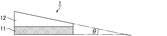
- FIGS. 1 to 3 are schematic diagrams for explaining an example of the case where the cross-sectional shape of the interlayer film for laminated glass of the present invention is a wedge shape.
- the thickness and wedge angle ⁇ of the interlayer film for laminated glass and each layer constituting the interlayer film for laminated glass are shown to be different from the actual thickness and wedge angle. Yes.
- FIG. 1 shows a cross section in the thickness direction of the interlayer film 1 for laminated glass.
- the interlayer film 1 for laminated glass has a two-layer structure in which a shape auxiliary layer 12 is laminated on one surface of a light emitting layer 11 containing a light emitting material.
- the light emitting layer 11 has a rectangular shape
- the shape auxiliary layer 12 has a wedge shape, a triangular shape, or a trapezoidal shape, so that the laminated film intermediate film 1 has a wedge angle ⁇ of 0.1 to 1 mrad as a whole. It has a wedge shape.
- FIG. 2 shows a cross section in the thickness direction of the interlayer film 2 for laminated glass.
- the interlayer film 2 for laminated glass has a three-layer structure in which a shape auxiliary layer 22 and a shape auxiliary layer 23 are laminated on both surfaces of a light emitting layer 21 containing a light emitting material.
- the shape auxiliary layer 22 is wedge-shaped, triangular, or trapezoidal so that the interlayer film 2 for laminated glass as a whole is wedged.
- the wedge shape has an angle ⁇ of 0.1 to 1 mrad.
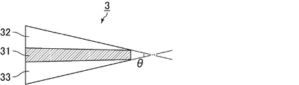
- FIG. 3 shows a cross section in the thickness direction of the interlayer film 3 for laminated glass.
- the interlayer film 3 for laminated glass has a three-layer structure in which a shape auxiliary layer 32 and a shape auxiliary layer 33 are laminated on both surfaces of a light emitting layer 31 containing a light emitting material.
- the light emitting layer 31 has a gentle wedge shape with a difference between the maximum thickness and the minimum thickness of 100 ⁇ m or less.
- the wedge angle ⁇ of the laminated glass intermediate film 3 as a whole is increased. It has a wedge shape of 0.1 to 1 mrad.
- the method for producing the interlayer film for laminated glass of the present invention is not particularly limited.
- a plasticizer solution containing a plasticizer and a lanthanoid complex and a thermoplastic resin are sufficiently mixed to produce a resin composition for forming a light emitting layer.
- the resin composition for forming the light emitting layer can be extruded using an extruder to produce an interlayer film for laminated glass.
- the interlayer film for laminated glass of the present invention has the light emitting layer, it emits light when irradiated with light having a specific wavelength. By utilizing this property, information can be displayed with high contrast.
- a spot light source manufactured by Hamamatsu Photonics, LC-8
- a xenon flash lamp manufactured by Heraeus, CW lamp
- a black light manufactured by Inoue Seieido
- Carry hand for example, a spot light source (manufactured by Hamamatsu Photonics, LC-8), a xenon flash lamp (manufactured by Heraeus, CW lamp), a black light (manufactured by Inoue Seieido) , Carry hand) and the like.
- the laminated glass in which the interlayer film for laminated glass of the present invention is laminated between a pair of glass plates is also one aspect of the present invention.
- the said glass plate can use the transparent plate glass generally used. Examples thereof include inorganic glass such as float plate glass, polished plate glass, template glass, netted glass, wire-containing plate glass, colored plate glass, heat ray absorbing glass, heat ray reflecting glass, and green glass.
- inorganic glass such as float plate glass, polished plate glass, template glass, netted glass, wire-containing plate glass, colored plate glass, heat ray absorbing glass, heat ray reflecting glass, and green glass.
- the ultraviolet shielding glass in which the ultraviolet shielding coating layer was formed in the glass surface can be used, it is preferable to use as a glass plate opposite to the side irradiated with the light ray of a specific wavelength.
- organic plastics plates such as polyethylene terephthalate, polycarbonate, and polyacrylate can be used as the glass plate.
- glass plate Two or more types of glass plates may be used as the glass plate.
- stacked the intermediate film for laminated glasses of this invention between transparent float plate glass and colored glass plates like green glass is mentioned.
- an interlayer film for laminated glass that can display an image with high emission intensity by irradiating light and has excellent durability, and a laminated glass including the interlayer film for laminated glass are provided. can do.
- PVB1-1 polyvinyl butyral 1-1
- PVB1-2 polyvinyl butyral 1-2
- the amount of acetyl groups in PVB1-2 was 1 mol%, the amount of butyral groups was 69 mol%, and the amount of hydroxyl groups was 30 mol%.
- PVB1-3 polyvinyl butyral 1-3
- the amount of acetyl groups in PVB1-3 was 1 mol%, the amount of butyral groups was 69 mol%, and the amount of hydroxyl groups was 30 mol%.
- PVB1-4 polyvinyl butyral 1-4
- the amount of acetyl groups in PVB1-4 was 1 mol%, the amount of butyral groups was 69 mol%, and the amount of hydroxyl groups was 30 mol%.
- PVB1-5 polyvinyl butyral 1-5
- PVB1-6 polyvinyl butyral 1-6
- PVB1-7 polyvinyl butyral 1-7
- the amount of acetyl groups in PVB1-7 was 1 mol%, the amount of butyral groups was 69 mol%, and the amount of hydroxyl groups was 30 mol%.
- PVB1-8 polyvinyl butyral 1-8
- the amount of acetyl groups in PVB1-8 was 1 mol%, the amount of butyral groups was 69 mol%, and the amount of hydroxyl groups was 30 mol%.
- PVB2-1 polyvinyl butyral 2-1
- the amount of acetyl groups in PVB2-1 was 12 mol%, the amount of butyral groups was 66 mol%, and the amount of hydroxyl groups was 22 mol%.
- PVB2-2 polyvinyl butyral 2-2
- the amount of acetyl groups in PVB2-2 was 12 mol%, the amount of butyral groups was 66 mol%, and the amount of hydroxyl groups was 22 mol%.
- Example 1 (1) Preparation of Eu (TFA) 3 phen Europium acetate (Eu (CH 3 COO) 3 ) 5 g (12.5 mmol) was dissolved in 50 mL of distilled water, and trifluoroacetylacetone (TFA, CH 3 COCH 2 COCF 3 ) 7 g (33.6 mmol) was added and stirred at room temperature for 3 hours. The precipitated solid was filtered, washed with water, and recrystallized with methanol and distilled water to obtain Eu (TFA) 3 (H 2 O) 2 .
- the obtained interlayer film for laminated glass was laminated between a pair of clear glass (thickness 2.5 mm) having a length of 5 cm and a width of 5 cm to obtain a laminate.
- the obtained laminate was vacuum-pressed while being held at 90 ° C. for 30 minutes with a vacuum laminator to be pressure-bonded. After the pressure bonding, pressure bonding was performed for 20 minutes using an autoclave under conditions of 140 ° C. and 14 MPa to obtain a laminated glass.
- Example 2 (1) instead of Eu (TFA) 3 dpphen
- Example 3 (1) instead of Eu (HFA) 3 phen adjustment trifluoroacetylacetone, except for using hexafluoroacetylacetone in the same manner as in Example 1 to obtain a Eu (HFA) 3 phen.
- Example 4 (1) instead of Tb (TFA) 3 phen adjustment europium acetate, except for using acetic acid terbium in the same manner as in Example 1 to obtain a Tb (TFA) 3 phen.
- Example 5 An interlayer film for laminated glass and laminated glass were produced in the same manner as in Example 1 except that the types of polyvinyl butyral resin and luminescent particles were changed as shown in Table 1.
- Comparative Example 1 An interlayer film for laminated glass and a laminated glass were produced in the same manner as in Example 2 except that the polyvinyl butyral resin used was changed to PVB1-5.
- Comparative Example 2 An interlayer film for laminated glass and a laminated glass were produced in the same manner as in Example 2 except that the polyvinyl butyral resin used was changed to PVB1-6.
- Example 8 to 12 Comparative Examples 5 to 6
- An interlayer film for laminated glass and laminated glass were produced in the same manner as in Example 1 except that the type of polyvinyl butyral resin, the type of luminescent particles, and the content of luminescent particles were changed as shown in Table 2.
- Example 13 0.2 parts by weight of Eu (HFA) 3 phen obtained in Example 3 was added to 40 parts by weight of triethylene glycol di-2-ethylhexanoate (3GO), and further tin-doped indium oxide particles as a heat ray absorbent An amount of 0.15% by weight in 100% by weight of the intermediate film from which (ITO particles) can be obtained was added to prepare a luminescent plasticizer solution.
- a resin composition was prepared by sufficiently kneading the total amount of the obtained plasticizer solution and 100 parts by weight of the obtained PVB1-1 with a mixing roll. The obtained resin composition was extruded using an extruder to obtain an interlayer film for laminated glass (thickness: 760 ⁇ m).
- the obtained interlayer film for laminated glass was laminated between a pair of clear glass (thickness 2.5 mm) having a length of 5 cm and a width of 5 cm to obtain a laminate.
- the obtained laminate was vacuum-pressed while being held at 90 ° C. for 30 minutes with a vacuum laminator to be pressure-bonded. After the pressure bonding, pressure bonding was performed for 20 minutes using an autoclave under conditions of 140 ° C. and 14 MPa to obtain a laminated glass.
- Example 14 0.2 parts by weight of Eu (HFA) 3 phen obtained in Example 3 was added to 40 parts by weight of triethylene glycol di-2-ethylhexanoate (3GO), and cesium-doped tungsten oxide ( An amount of 0.05% by weight in 100% by weight of the intermediate film from which Cs0.33WO3) particles (CWO particles) can be obtained was added to prepare a luminescent plasticizer solution.
- a resin composition was prepared by sufficiently kneading the total amount of the obtained plasticizer solution and 100 parts by weight of the obtained PVB1-1 with a mixing roll. The obtained resin composition was extruded using an extruder to obtain an interlayer film for laminated glass (thickness: 760 ⁇ m).
- the obtained interlayer film for laminated glass was laminated between a pair of clear glass (thickness 2.5 mm) having a length of 5 cm and a width of 5 cm to obtain a laminate.
- the obtained laminate was vacuum-pressed while being held at 90 ° C. for 30 minutes with a vacuum laminator to be pressure-bonded. After the pressure bonding, pressure bonding was performed for 20 minutes using an autoclave under conditions of 140 ° C. and 14 MPa to obtain a laminated glass.
- Example 15 and 16 An interlayer film for laminated glass and laminated glass were produced in the same manner as in Example 13 except that the type of luminescent particles, the type of heat ray absorbent, and the content of the heat ray absorbent were changed as shown in Table 3.
- Example 17 (Preparation of resin composition for light emitting layer) To 40 parts by weight of triethylene glycol di-2-ethylhexanoate (3GO), 0.5 part by weight of Eu (HFA) 3 phen obtained in Example 3 was added to prepare a luminescent plasticizer solution. The total amount of the obtained plasticizer solution and 100 parts by weight of PVB1-1 were sufficiently kneaded with a mixing roll to prepare a light emitting layer resin composition.
- 3GO triethylene glycol di-2-ethylhexanoate
- HFA Eu
- a resin composition for an adhesive layer was prepared by sufficiently kneading 40 parts by weight of triethylene glycol di-2-ethylhexanoate (3GO) and 100 parts by weight of PVB1-9 with a mixing roll.
- 3GO triethylene glycol di-2-ethylhexanoate
- an interlayer film for laminated glass (thickness 0) in which the light emitting layer is laminated between the two adhesive layers. 8 mm).
- the thickness of the light emitting layer was 0.1 mm
- the thickness of the adhesive layer was 0.35 mm.
- the obtained interlayer film for laminated glass was laminated between a pair of clear glass (thickness 2.5 mm) having a length of 5 cm and a width of 5 cm to obtain a laminate.
- the obtained laminate was vacuum-pressed while being held at 90 ° C. for 30 minutes with a vacuum laminator to be pressure-bonded. After the pressure bonding, pressure bonding was performed for 20 minutes using an autoclave under conditions of 140 ° C. and 14 MPa to obtain a laminated glass.
- the obtained interlayer film for laminated glass was laminated between a pair of clear glass (thickness 2.5 mm) 30 cm long and 30 cm wide to obtain a laminate.
- the obtained laminate was vacuum-pressed while being held at 90 ° C. for 30 minutes with a vacuum laminator to be pressure-bonded. After the pressure bonding, pressure bonding was performed for 20 minutes using an autoclave under conditions of 140 ° C. and 14 MPa, and the intermediate film portion protruding from the glass was cut off to obtain a laminated glass for penetration resistance evaluation.
- Example 18 to 21, Comparative Examples 7 to 8 An interlayer film for laminated glass and laminated glass were produced in the same manner as in Example 17 except that the type of polyvinyl butyral resin, the type of luminescent particles, and the content of the plasticizer were changed as shown in Table 4.
- Example 22 (Preparation of resin composition for light emitting layer) To 40 parts by weight of triethylene glycol di-2-ethylhexanoate (3GO), 0.5 part by weight of Eu (HFA) 3 phen obtained in Example 3 was added to prepare a luminescent plasticizer solution. The total amount of the obtained plasticizer solution and 100 parts by weight of PVB1-1 were sufficiently kneaded with a mixing roll to prepare a light emitting layer resin composition.
- 3GO triethylene glycol di-2-ethylhexanoate
- HFA Eu
- a resin composition for an auxiliary shape layer was prepared by sufficiently kneading 40 parts by weight of triethylene glycol di-2-ethylhexanoate (3GO) and 100 parts by weight of PVB1-9 with a mixing roll.
- 3GO triethylene glycol di-2-ethylhexanoate
- the resin composition for the light emitting layer and the resin composition for the shape auxiliary layer were coextruded using a coextrusion machine, and the shape auxiliary layer, the light emitting layer, and the shape auxiliary layer were laminated in this order.
- An interlayer film for laminated glass having a three-layer structure was obtained.
- the extrusion direction of the obtained interlayer film was 1 m when the shortest distance between one end and the other end in the vertical direction was measured.
- the light emitting layer in the obtained interlayer film for laminated glass has a wedge-shaped cross-sectional shape having a minimum thickness of 100 ⁇ m and a maximum thickness of 200 ⁇ m.
- the entire interlayer film for laminated glass has a minimum thickness of 800 ⁇ m, a maximum thickness of 1250 ⁇ m, and a wedge angle ⁇ 0.45 mrad. It had a wedge-shaped cross-sectional shape.
- One end of the interlayer film for laminated glass has a minimum thickness and the other end has a maximum thickness, and the minimum thickness and the maximum thickness were measured by observation with an optical microscope.
- the obtained interlayer film was sandwiched between two transparent float glasses (length 1000 mm ⁇ width 300 mm ⁇ thickness 2.5 mm) to obtain a laminate.
- the obtained laminated body was temporarily press-bonded using a 230 ° C. heating roll. Then, the laminated body temporarily crimped
- An intermediate film (thin portion) 10 cm long ⁇ 10 cm wide was cut out so that a point 10 cm from the one end on the shortest distance between the one end and the other end was the center.
- the obtained intermediate film (thin portion) was sandwiched between two transparent float glasses (5 cm long ⁇ 5 cm wide ⁇ 2.5 mm thick) to obtain a laminate.
- the obtained laminated body was temporarily press-bonded using a 230 ° C. heating roll. Then, the laminated body temporarily crimped
- Example 23 to 25 Comparative Examples 9 to 10.
- the interlayer film for laminated glass and the laminated glass were prepared in the same manner as in Example 22 except that the kind of polyvinyl butyral resin, the kind of luminescent particles, the maximum thickness of the entire interlayer film and the wedge angle ⁇ were changed as shown in Table 5. Manufactured.
- Example 26 (Preparation of resin composition for light emitting layer) 0.2 parts by weight of Eu (HFA) 3 phen obtained in Example 3 was added to 40 parts by weight of triethylene glycol di-2-ethylhexanoate (3GO) to prepare a luminescent plasticizer solution. The total amount of the obtained plasticizer solution and 100 parts by weight of PVB1-1 were sufficiently kneaded with a mixing roll to prepare a light emitting layer resin composition.
- a resin composition for an auxiliary shape layer was prepared by sufficiently kneading 40 parts by weight of triethylene glycol di-2-ethylhexanoate (3GO) and 100 parts by weight of PVB1-1 with a mixing roll.
- 3GO triethylene glycol di-2-ethylhexanoate
- a sound insulation layer resin composition was prepared by sufficiently kneading 60 parts by weight of triethylene glycol di-2-ethylhexanoate (3GO) and 100 parts by weight of PVB2-1 with a mixing roll.
- 3GO triethylene glycol di-2-ethylhexanoate
- the resin composition for the light emitting layer was extruded as a single layer using an extruder to obtain a light emitting layer (thickness: 760 ⁇ m).
- the first resin layer, the sound insulation layer, and the second resin layer resin composition and the sound insulation layer resin composition are coextruded using a coextrusion machine.
- a laminate having a three-layer structure illustrated in FIG. 3 was obtained in which the resin layers were laminated in this order.
- the light emitting layer was laminated
- the shortest distance between one end and the other end in the direction perpendicular to the direction of extrusion of the intermediate film was 1 m.
- the sound insulating layer in the interlayer film for laminated glass thus obtained has a wedge-shaped cross-sectional shape with a minimum thickness of 100 ⁇ m and a maximum thickness of 200 ⁇ m, and the first resin layer has a wedge-shaped cross-sectional shape with a minimum thickness of 350 ⁇ m and a maximum thickness of 525 ⁇ m.
- the second resin layer has a wedge-shaped cross-sectional shape with a minimum thickness of 350 ⁇ m and a maximum thickness of 525 ⁇ m
- the entire interlayer film for laminated glass has a wedge-shaped cross-sectional shape with a minimum thickness of 1560 ⁇ m, a maximum thickness of 2010 ⁇ m, and a wedge angle ⁇ 0.45 mrad.
- One end of the interlayer film for laminated glass has a minimum thickness and the other end has a maximum thickness, and the minimum thickness and the maximum thickness were measured by observation with an optical microscope.
- the obtained interlayer film was sandwiched between two transparent float glasses (length 1000 mm ⁇ width 300 mm ⁇ thickness 2.5 mm) to obtain a laminate.
- the obtained laminated body was temporarily press-bonded using a 230 ° C. heating roll. Then, the laminated body temporarily crimped
- An intermediate film (thin portion) 10 cm long ⁇ 10 cm wide was cut out so that a point 10 cm from the one end on the shortest distance between the one end and the other end was the center.
- the obtained intermediate film (thin portion) was sandwiched between two transparent float glasses (5 cm long ⁇ 5 cm wide ⁇ 2.5 mm thick) to obtain a laminate.
- the obtained laminated body was temporarily press-bonded using a 230 ° C. heating roll. Then, the laminated body temporarily crimped
- Example 27 Comparative Examples 11 to 12
- An interlayer film for laminated glass and laminated glass were produced in the same manner as in Example 26 except that the type of polyvinyl butyral resin and the type of luminescent particles were changed as shown in Table 6.
- the laminated glass obtained in Examples 1 to 29 and Comparative Examples 1 to 12 was cooled with liquid nitrogen so that the glass and the interlayer film for laminated glass were peeled off.
- the peeled interlayer film for laminated glass was left to stand in an environment of a temperature of 25 ° C. and a humidity of 30% for 2 hours. Since the laminated glass obtained in Examples 17 to 29 and Comparative Examples 7 to 12 has a multilayered interlayer film for laminated glass, each layer was peeled by the following procedure. A finger was put between the light emitting layer and the adhesive layer, and peeling was performed at a speed of 1 to 5 cm / s. After peeling, the light emitting layer and the adhesive layer were allowed to stand for 2 hours in an environment of a temperature of 25 ° C.
- the shape auxiliary layer, the first resin layer, the sound insulation layer, and the second resin layer were peeled by the same procedure.
- the light emitting layer, the adhesive layer, the shape auxiliary layer, the first resin layer, the sound insulation layer, and the second resin layer are each cut into a size of 0.5 cm ⁇ 0.5 cm, and a weight is measured after taking a measurement sample. did.
- the obtained measurement sample was dissolved in 45 mL of chloroform, and then 50 mL of ion-exchanged water was added and shaken for 1 hour, and then allowed to stand to cause phase separation. After phase separation, the aqueous phase was extracted and used as measurement solution 1.
- aqueous phase After extraction of the aqueous phase, 50 mL of ion-exchanged water was added again, and the same operation was performed. After the phase separation, the aqueous phase was extracted and used as Measurement Solution 2.
- An ion chromatograph manufactured by Diionex (ICS-2000 type was used to measure the concentrations of nitric acid component and carbonic acid component contained in measuring liquid 1 and measuring liquid 2 by the electric conductivity detection method. From the concentration and the weight of the measurement sample, the contents of the nitric acid component and the carbonic acid component contained in the light emitting layer, the adhesive layer, the shape auxiliary layer, the first resin layer, the sound insulating layer, and the second resin layer were calculated.
- the laminated glass of 5 cm ⁇ 5 cm was irradiated with ultraviolet rays for 1000 hours with a JIS-UV tester (750 W, the light source was quartz glass mercury lamp).
- the laminated glass that had been irradiated with ultraviolet rays was measured for luminance after irradiation with ultraviolet rays in the same manner as the initial luminance.
- the case where the luminance after UV irradiation was 50% or more of the initial luminance was evaluated as “ ⁇ ”, and the case where the luminance was less than 50% was evaluated as “X”.
- Penetration resistance evaluation (measurement of Pummel value of interlayer film for laminated glass)
- the laminated glass for evaluation of penetration resistance obtained in Examples 17 to 21 and Comparative Examples 7 to 8 was adjusted to a temperature of ⁇ 18 ° C. ⁇ 0.6 ° C. for 16 hours, and the central portion of this laminated glass (length 150 mm ⁇ width 150mm portion) is smashed with a hammer having a head of 0.45kg and pulverized until the glass particle size is 6mm or less. The degree of exposure of the film after the glass is partially peeled is measured. Asked.
- an interlayer film for laminated glass that can display an image with high emission intensity by irradiating light and has excellent durability, and a laminated glass including the interlayer film for laminated glass are provided. can do.
Abstract
Description
HUDとしては、これまでに数々の形態が開発されている。最も一般的なHUDとしてコントロールユニットから送信される速度情報等をインストゥルメンタル・パネルの表示ユニットからフロントガラスに反射させることにより、運転者がフロントガラスと同じ位置、すなわち、同一視野内で速度情報等を視認できるHUDがある。
HUD用の合わせガラス用中間膜として、例えば、特許文献1には、所定の楔角を有する楔形合わせガラス用中間膜等が提案されており、合わせガラスにおいて計器表示が二重に見えるというHUDの欠点を解決することが提案されている。 In recent years, there has been a growing demand to display instrument displays such as speed information, which is automobile travel data, as a head-up display (HUD) within the same field of view as an automobile windshield.
A number of forms have been developed as HUDs so far. By reflecting the speed information transmitted from the control unit as the most common HUD to the windshield from the display unit of the instrument panel, the driver can obtain the speed information at the same position as the windshield, that is, within the same field of view. There is a HUD that can be visually recognized.
As an interlayer film for laminated glass for HUD, for example,
しかしながら、ランタノイド錯体を用いて合わせガラス用中間膜を製造しても、長期間紫外線下にさらされたときに発光強度が低下してしまうという耐久性低下の問題が発生した。
本発明は、上記現状に鑑み、光線を照射することにより高い発光強度で画像を表示することができ、かつ、耐久性に優れる合わせガラス用中間膜、及び、該合わせガラス用中間膜を含む合わせガラスを提供することを目的とする。 In order to display a higher-contrast image in a light-emitting sheet containing a light-emitting material, it is important to select a light-emitting material with higher emission intensity. As a result of intensive studies, the present inventors have found that lanthanoid complexes exhibit extremely high emission intensity.
However, even when an interlayer film for laminated glass is produced using a lanthanoid complex, there has been a problem of a decrease in durability that the emission intensity decreases when exposed to ultraviolet rays for a long time.
In view of the above-mentioned present situation, the present invention can display an image with high emission intensity by irradiating light, and has excellent durability, and a laminated glass including the laminated glass interlayer film. The object is to provide glass.
以下に本発明を詳述する。 The present invention is an interlayer film for laminated glass having a light emitting layer containing a polyvinyl acetal resin and a lanthanoid complex as light emitting particles, wherein the total content of nitric acid component and carbonic acid component contained in the light emitting layer is 100 ppm. It is the following interlayer film for laminated glass.
The present invention is described in detail below.
合わせガラス用中間膜中には、熱可塑性樹脂製造時に用いた中和剤等の原料に由来する硝酸成分や炭酸成分が含まれる。このような合わせガラス用中間膜にランタノイド錯体を配合すると、硝酸成分や炭酸成分とランタノイド錯体とが相互作用して、ランタノイド錯体の耐久性が低下すると考えられた。
本発明者らは、更に鋭意検討の結果、合わせガラス用中間膜中に含まれる硝酸成分と炭酸成分との合計の含有量を一定以下とすることにより、ランタノイド錯体を用いた場合にでも、耐久性が低下するのを防止できることを見出し、本発明を完成させるに至った。 The inventors of the present invention have studied the cause of the decrease in durability when an interlayer film for laminated glass is produced using a lanthanoid complex. As a result, it has been found that the cause is a nitric acid component or a carbonic acid component contained in the interlayer film for laminated glass.
The interlayer film for laminated glass contains a nitric acid component and a carbonic acid component derived from raw materials such as a neutralizing agent used during the production of the thermoplastic resin. It was considered that when a lanthanoid complex was blended with such an interlayer film for laminated glass, the nitric acid component or carbonic acid component interacted with the lanthanoid complex, and the durability of the lanthanoid complex was lowered.
As a result of further intensive studies, the inventors have determined that the total content of the nitric acid component and the carbonic acid component contained in the interlayer film for laminated glass is not more than a certain level, so that even when a lanthanoid complex is used, it is durable. As a result, the inventors have found that it is possible to prevent deterioration of the properties, and have completed the present invention.
上記ポリビニルアセタールのアセタール化度の好ましい下限は40モル%、好ましい上限は85モル%であり、より好ましい下限は60モル%、より好ましい上限は75モル%である。 The polyvinyl acetal is not particularly limited as long as it is a polyvinyl acetal obtained by acetalizing polyvinyl alcohol with an aldehyde, but polyvinyl butyral is preferable. Moreover, you may use together 2 or more types of polyvinyl acetal as needed.
The preferable lower limit of the degree of acetalization of the polyvinyl acetal is 40 mol%, the preferable upper limit is 85 mol%, the more preferable lower limit is 60 mol%, and the more preferable upper limit is 75 mol%.
なお、上記アセタール化度及び水酸基量は、例えば、JIS K6728「ポリビニルブチラール試験方法」に準拠して測定できる。 The polyvinyl acetal has a preferred lower limit of the hydroxyl group content of 15 mol% and a preferred upper limit of 35 mol%. When the hydroxyl group amount is 15 mol% or more, the interlayer film for laminated glass can be easily molded. When the amount of hydroxyl group is 35 mol% or less, handling of the resulting interlayer film for laminated glass becomes easy.
The degree of acetalization and the amount of hydroxyl groups can be measured in accordance with, for example, JIS K6728 “Testing method for polyvinyl butyral”.
上記ポリビニルアルコールの重合度の好ましい下限は500、好ましい上限は4000である。上記ポリビニルアルコールの重合度が500以上であると、得られる合わせガラスの耐貫通性が高くなる。上記ポリビニルアルコールの重合度が4000以下であると、合わせガラス用中間膜の成形が容易になる。上記ポリビニルアルコールの重合度のより好ましい下限は1000、より好ましい上限は3600である。 The polyvinyl acetal can be prepared by acetalizing polyvinyl alcohol with an aldehyde. The polyvinyl alcohol is usually obtained by saponifying polyvinyl acetate, and polyvinyl alcohol having a saponification degree of 70 to 99.8 mol% is generally used.
The preferable lower limit of the polymerization degree of the polyvinyl alcohol is 500, and the preferable upper limit is 4000. When the polymerization degree of the polyvinyl alcohol is 500 or more, the penetration resistance of the obtained laminated glass is increased. When the polymerization degree of the polyvinyl alcohol is 4000 or less, the interlayer film for laminated glass can be easily molded. The minimum with a more preferable polymerization degree of the said polyvinyl alcohol is 1000, and a more preferable upper limit is 3600.
なかでも、300~410nmの波長の光を照射することにより、580~780nmの波長の光を極めて高い発光強度で発光し、これを用いることによりコントラストが高い画像を表示できる合わせガラス用中間膜が得られることから、ハロゲン原子を含む二座配位子を有するランタノイド錯体又はハロゲン原子を含む三座配位子を有するランタノイド錯体が好適である。 The lanthanoid complex includes, for example, a hydrogen atom, a deuterium atom, a halogen atom, an alkyl group having 1 to 20 carbon atoms, a nitro group, a hydroxyl group, an amino group, a sulfonyl group, a cyano group, a phosphone group, a phosphate group, and a diazo group. And a lanthanoid complex having a monodentate ligand, a bidentate ligand, a tridentate ligand or a tetradentate ligand.
In particular, an interlayer film for laminated glass that can emit light having a wavelength of 580 to 780 nm with an extremely high emission intensity by irradiating light having a wavelength of 300 to 410 nm, and can display an image with high contrast by using the light. Since it is obtained, a lanthanoid complex having a bidentate ligand containing a halogen atom or a lanthanoid complex having a tridentate ligand containing a halogen atom is preferable.
上記ハロゲン原子を含む三座配位子を有するランタノイド錯体は、例えば、ターピリジントリフルオロアセチルアセトンユーロピウム、ターピリジンヘキサフルオロアセチルアセトンユーロピウム等が挙げられる。 Examples of the lanthanoid complex having a bidentate ligand containing a halogen atom include tris (trifluoroacetylacetone) phenanthroline europium, tris (trifluoroacetylacetone) diphenylphenanthroline europium, tris (hexafluoroacetylacetone) diphenylphenanthroline europium, and tris (hexa). Fluoroacetylacetone) bis (triphenylphosphine) europium, tris (trifluoroacetylacetone) 2,2′-bipyridine europium, tris (hexafluoroacetylacetone) 2,2′-bipyridine europium, and the like.
Examples of the lanthanoid complex having a tridentate ligand containing a halogen atom include terpyridine trifluoroacetylacetone europium, terpyridine hexafluoroacetylacetone europium, and the like.
上記ハロゲン原子を含みアセチルアセトン骨格を有する二座配位子を有するランタノイド錯体は、例えば、Eu(TFA)3phen、Eu(TFA)3dpphen、Eu(HFA)3phen、[Eu(FOD)3]bpy、[Eu(TFA)3]tmphen、[Eu(FOD)3]phen等が挙げられる。これらのハロゲン原子を含みアセチルアセトン骨格を有する二座配位子を有するランタノイド錯体の構造を示す。 Among the lanthanoid complexes having a bidentate ligand containing a halogen atom or the lanthanoid complexes having a tridentate ligand containing a halogen atom, the lanthanoid complex having a halogen atom and an acetylacetone skeleton is particularly excellent in initial light emission. Lanthanoid complexes having a bidentate ligand are preferred.
Examples of the lanthanoid complex having a bidentate ligand containing a halogen atom and having an acetylacetone skeleton include Eu (TFA) 3 phen, Eu (TFA) 3 dpphen, Eu (HFA) 3 phen, and [Eu (FOD) 3 ]. bpy, [Eu (TFA) 3 ] tmphen, [Eu (FOD) 3 ] phen and the like. The structure of a lanthanoid complex having a bidentate ligand containing these halogen atoms and having an acetylacetone skeleton is shown.

上記ランタノイド錯体が粒子状である場合、上記ランタノイド錯体の平均粒子径の好ましい下限は0.01μm、好ましい上限は10μmであり、より好ましい下限は0.03μm、より好ましい上限は1μmである。 The lanthanoid complex is preferably particulate. By being particulate, it becomes easier to finely disperse the lanthanoid complex in the interlayer film for laminated glass.
When the lanthanoid complex is particulate, the preferred lower limit of the average particle size of the lanthanoid complex is 0.01 μm, the preferred upper limit is 10 μm, the more preferred lower limit is 0.03 μm, and the more preferred upper limit is 1 μm.
なお、本明細書において硝酸成分とは、1個の窒素原子及び3個の酸素原子を有するNO3を意味する。また、本明細書において炭酸成分とは、1個の炭素原子及び3個の酸素原子を有するCO3を意味する。
上記発光層中の硝酸成分及び炭酸成分の含有量は、イオンクロマトグラフによる方法により測定することができる。 The total content of the nitric acid component and the carbonic acid component contained in the light emitting layer is 100 ppm or less. By setting the total content of the nitric acid component and the carbonic acid component to 100 ppm or less, it is possible to prevent the durability of the lanthanoid complex used in combination from decreasing. The total content of the nitric acid component and the carbonic acid component contained in the light emitting layer is preferably 60 ppm or less, and more preferably 50 ppm or less.
In the present specification, the nitric acid component means NO 3 having one nitrogen atom and three oxygen atoms. In the present specification, the carbonic acid component means CO 3 having one carbon atom and three oxygen atoms.
The contents of the nitric acid component and the carbonic acid component in the light emitting layer can be measured by a method using ion chromatography.
上記分散剤は、例えば、直鎖アルキルベンゼンスルホン酸塩等のスルホン酸構造を有する化合物や、ジエステル化合物、リシノール酸アルキルエステル、フタル酸エステル、アジピン酸エステル、セバシン酸エステル、リン酸エステル等のエステル構造を有する化合物や、ポリオキシエチレングリコール、ポリオキシプロピレングリコールやアルキルフェニル-ポリオキシエチレン-エーテル等のエーテル構造を有する化合物や、ポリカルボン酸等のカルボン酸構造を有する化合物や、ラウリルアミン、ジメチルラウリルアミン、オレイルプロピレンジアミン、ポリオキシエチレンの2級アミン、ポリオキシエチレンの3級アミン、ポリオキシエチレンのジアミン等のアミン構造を有する化合物や、ポリアルキレンポリアミンアルキレンオキシド等のポリアミン構造を有する化合物や、オレイン酸ジエタノールアミド、アルカノール脂肪酸アミド等のアミド構造を有する化合物や、ポリビニルピロリドン、ポリエステル酸アマイドアミン塩等の高分子量型アミド構造を有する化合物等の分散剤を用いることができる。また、ポリオキシエチレンアルキルエーテルリン酸(塩)や高分子ポリカルボン酸、縮合リシノール酸エステル等の高分子量分散剤を用いてもよい。なお、高分子量分散剤とは、その分子量が1万以上である分散剤と定義される。 The light emitting layer preferably further contains a dispersant. By containing the dispersant, aggregation of the lanthanoid complex can be suppressed, and more uniform light emission can be obtained.
The dispersant is, for example, a compound having a sulfonic acid structure such as a linear alkylbenzene sulfonate, or an ester structure such as a diester compound, a ricinoleic acid alkyl ester, a phthalic acid ester, an adipic acid ester, a sebacic acid ester, or a phosphoric acid ester. , Compounds having an ether structure such as polyoxyethylene glycol, polyoxypropylene glycol and alkylphenyl-polyoxyethylene-ether, compounds having a carboxylic acid structure such as polycarboxylic acid, laurylamine, dimethyllauryl Compounds having an amine structure such as amines, oleylpropylenediamine, secondary amines of polyoxyethylene, tertiary amines of polyoxyethylene, and diamines of polyoxyethylene, and polyalkylenepolyaminealkyleneoxy Dispersants such as compounds having a polyamine structure such as amides, compounds having an amide structure such as oleic acid diethanolamide and alkanol fatty acid amide, and compounds having a high molecular weight amide structure such as polyvinylpyrrolidone and polyester acid amide amine salts Can be used. Moreover, you may use high molecular weight dispersing agents, such as polyoxyethylene alkyl ether phosphoric acid (salt), high molecular polycarboxylic acid, and condensed ricinoleic acid ester. The high molecular weight dispersant is defined as a dispersant having a molecular weight of 10,000 or more.
コントラストがより一層高い画像を表示できる合わせガラス用中間膜が得られることから、上記発光層中における上記紫外線吸収剤の含有量は、上記熱可塑性樹脂100重量部に対する好ましい上限は1重量部、より好ましい上限は0.5重量部、更に好ましい上限は0.2重量部、特に好ましい上限は0.1重量部である。 The light emitting layer may further contain an ultraviolet absorber. When the light emitting layer contains an ultraviolet absorber, the light resistance of the light emitting layer is increased.
Since an interlayer film for laminated glass capable of displaying an image with higher contrast can be obtained, the content of the ultraviolet absorber in the light emitting layer is preferably 1 part by weight, more preferably 100 parts by weight of the thermoplastic resin. A preferred upper limit is 0.5 parts by weight, a more preferred upper limit is 0.2 parts by weight, and a particularly preferred upper limit is 0.1 parts by weight.
上記可塑剤は特に限定されず、例えば、一塩基性有機酸エステル、多塩基性有機酸エステル等の有機エステル可塑剤、有機リン酸可塑剤、有機亜リン酸可塑剤等のリン酸可塑剤等が挙げられる。上記可塑剤は液状可塑剤であることが好ましい。 The light emitting layer may further contain a plasticizer.
The plasticizer is not particularly limited, and examples thereof include organic ester plasticizers such as monobasic organic acid esters and polybasic organic acid esters, phosphoric acid plasticizers such as organic phosphoric acid plasticizers and organic phosphorous acid plasticizers, and the like. Is mentioned. The plasticizer is preferably a liquid plasticizer.
上記酸化防止剤は特に限定されず、フェール構造を有する酸化防止剤、硫黄を含む酸化防止剤、リンを含む酸化防止剤等が挙げられる。
上記フェノール構造を有する酸化防止剤はフェノール骨格を有する酸化防止剤である。上記フェノール構造を有する酸化防止剤としては、例えば、2,6-ジ-t-ブチル-p-クレゾール(BHT)、ブチル化ヒドロキシアニソール(BHA)、2,6-ジ-t-ブチル-4-エチルフェノール、ステアリル-β-(3,5-ジ-t-ブチル-4-ヒドロキシフェニル)プロピオネート、2,2’-メチレンビス-(4-メチル-6-ブチルフェノール)、2,2’-メチレンビス-(4-エチル-6-t-ブチルフェノール)、4,4’-ブチリデン-ビス-(3-メチル-6-t-ブチルフェノール)、1,1,3-トリス-(2-メチル-ヒドロキシ-5-t-ブチルフェニル)ブタン、テトラキス[メチレン-3-(3’,5’-ブチル-4-ヒドロキシフェニル)プロピオネート]メタン、1,3,3-トリス-(2-メチル-4-ヒドロキシ-5-t-ブチルフェノール)ブタン、1,3,5-トリメチル-2,4,6-トリス(3,5-ジ-t-ブチル-4-ヒドロキシベンジル)ベンゼン、ビス(3,3’-t-ブチルフェノール)ブチリックアッシドグリコールエステル、ペンタエリスリトールテトラキス[3-(3,5-ジ-tert-ブチル-4-ヒドロキシフェニル)プロピオナート]等が挙げられる。上記酸化防止剤は、単独で用いてもよいし、2種以上を併用してもよい。 Since the said light emitting layer can acquire the outstanding light resistance, it is preferable to contain antioxidant.
The antioxidant is not particularly limited, and examples thereof include an antioxidant having a fail structure, an antioxidant containing sulfur, and an antioxidant containing phosphorus.
The antioxidant having the phenol structure is an antioxidant having a phenol skeleton. Examples of the antioxidant having a phenol structure include 2,6-di-t-butyl-p-cresol (BHT), butylated hydroxyanisole (BHA), 2,6-di-t-butyl-4- Ethylphenol, stearyl-β- (3,5-di-t-butyl-4-hydroxyphenyl) propionate, 2,2′-methylenebis- (4-methyl-6-butylphenol), 2,2′-methylenebis- ( 4-ethyl-6-t-butylphenol), 4,4'-butylidene-bis- (3-methyl-6-t-butylphenol), 1,1,3-tris- (2-methyl-hydroxy-5-t -Butylphenyl) butane, tetrakis [methylene-3- (3 ', 5'-butyl-4-hydroxyphenyl) propionate] methane, 1,3,3-tris- (2-methyl) 4-hydroxy-5-tert-butylphenol) butane, 1,3,5-trimethyl-2,4,6-tris (3,5-di-tert-butyl-4-hydroxybenzyl) benzene, bis (3 , 3′-tert-butylphenol) butyric acid glycol ester, pentaerythritol tetrakis [3- (3,5-di-tert-butyl-4-hydroxyphenyl) propionate] and the like. The said antioxidant may be used independently and may use 2 or more types together.
本発明の合わせガラス用中間膜が多層構造である場合、上記発光層は合わせガラス用中間膜の全面に配置されていてもよく、一部にのみ配置されていてもよく、合わせガラス用中間膜の厚み方向とは垂直の面方向の全面に配置されていてもよく、一部にのみ配置されていてもよい。上記発光層が一部にのみ配置されている場合には、該一部を発光エリア、他の部分を非発光エリアとして、発光エリアにおいてのみ情報を表示できるようにすることができる。 The interlayer film for laminated glass of the present invention may have a single layer structure consisting only of the light emitting layer or a multilayer structure in which other layers are laminated.
When the interlayer film for laminated glass of the present invention has a multilayer structure, the light emitting layer may be disposed on the entire surface of the interlayer film for laminated glass, or may be disposed only on a part thereof. It may be arranged on the entire surface in a direction perpendicular to the thickness direction of the film, or may be arranged only in part. In the case where the light emitting layer is arranged only in part, information can be displayed only in the light emitting area, with the part as a light emitting area and the other part as a non-light emitting area.
例えば、本発明の合わせガラス用中間膜に遮音性能を付与するために、上記発光層における熱可塑性樹脂100重量部に対する可塑剤の含有量(以下、含有量Xともいう。)を、他の層における熱可塑性樹脂100重量部に対する可塑剤の含有量(以下、含有量Yともいう。)よりも多くすることができる。この場合、上記含有量Xは上記含有量Yよりも5重量部以上多いことが好ましく、10重量部以上多いことがより好ましく、15重量部以上多いことが更に好ましい。合わせガラス用中間膜の耐貫通性がより一層高くなることから、上記含有量Xと上記含有量Yとの差は、50重量部以下であることが好ましく、40重量部以下であることがより好ましく、35重量部以下であることが更に好ましい。なお、上記含有量Xと上記含有量Yとの差は、(上記含有量Xと上記含有量Yとの差)=(上記含有量X-上記含有量Y)により算出される。
また、上記含有量Xの好ましい下限が45重量部、より好ましい下限が50重量部、更に好ましい下限が55重量部、好ましい上限が80重量部、より好ましい上限が75重量部、さらに好ましい上限が70重量部である。上記含有量Xを上記好ましい下限以上とすることにより、高い遮音性を発揮することができる。上記含有量Xを上記好ましい上限以下とすることにより、可塑剤のブリードアウトの発生を抑止し、合わせガラス用中間膜の透明性や接着性の低下を防止することができる。
また、上記含有量Yの好ましい下限が20重量部、より好ましい下限が30重量部、更に好ましい下限が35重量部、好ましい上限が45重量部、より好ましい上限が43重量部、さらに好ましい上限が41重量部である。上記含有量Yを上記好ましい下限以上とすることにより、高い耐貫通性を発揮することができる。上記含有量Yを上記好ましい上限以下とすることにより、可塑剤のブリードアウトの発生を抑止し、合わせガラス用中間膜の透明性や接着性の低下を防止することができる。 When the interlayer film for laminated glass of the present invention has a multilayer structure, it is possible to impart various functions to the resulting interlayer film for laminated glass by adjusting the constituent components of the light emitting layer and other layers. .
For example, in order to impart sound insulation performance to the interlayer film for laminated glass of the present invention, the content of the plasticizer (hereinafter also referred to as content X) with respect to 100 parts by weight of the thermoplastic resin in the light emitting layer is changed to other layers. The content of the plasticizer relative to 100 parts by weight of the thermoplastic resin (hereinafter also referred to as “content Y”) can be increased. In this case, the content X is preferably 5 parts by weight or more, more preferably 10 parts by weight or more, and still more preferably 15 parts by weight or more than the content Y. Since the penetration resistance of the interlayer film for laminated glass is further enhanced, the difference between the content X and the content Y is preferably 50 parts by weight or less, more preferably 40 parts by weight or less. Preferably, it is 35 parts by weight or less. The difference between the content X and the content Y is calculated by (difference between the content X and the content Y) = (the content X−the content Y).
The preferred lower limit of the content X is 45 parts by weight, the more preferred lower limit is 50 parts by weight, the still more preferred lower limit is 55 parts by weight, the preferred upper limit is 80 parts by weight, the more preferred upper limit is 75 parts by weight, and the more preferred upper limit is 70 parts by weight. Parts by weight. By setting the content X to be equal to or more than the preferable lower limit, high sound insulation can be exhibited. By setting the content X to be equal to or less than the preferable upper limit, it is possible to suppress the occurrence of bleed out of the plasticizer and to prevent the transparency and adhesiveness of the interlayer film for laminated glass from being lowered.
Further, the preferred lower limit of the content Y is 20 parts by weight, the more preferred lower limit is 30 parts by weight, the still more preferred lower limit is 35 parts by weight, the preferred upper limit is 45 parts by weight, the more preferred upper limit is 43 parts by weight, and the more preferred upper limit is 41 parts. Parts by weight. By setting the content Y to be equal to or more than the preferable lower limit, high penetration resistance can be exhibited. By setting the content Y to be equal to or less than the preferable upper limit, it is possible to suppress the occurrence of bleeding out of the plasticizer and to prevent the transparency and adhesiveness of the interlayer film for laminated glass from being lowered.
上記熱線吸収剤は、赤外線を遮蔽する性能を有すれば特に限定されないが、錫ドープ酸化インジウム(ITO)粒子、アンチモンドープ酸化錫(ATO)粒子、アルミニウムドープ酸化亜鉛(AZO)粒子、インジウムドープ酸化亜鉛(IZO)粒子、錫ドープ酸化亜鉛粒子、珪素ドープ酸化亜鉛粒子、6ホウ化ランタン粒子及び6ホウ化セリウム粒子からなる群より選択される少なくとも1種が好適である。 In addition, for example, in order to impart heat shielding performance to the interlayer film for laminated glass of the present invention, any one of the light emitting layer and other layers, any two layers, or a heat ray absorbent in all layers. It can be included.
The heat ray absorber is not particularly limited as long as it has the ability to shield infrared rays, but is tin-doped indium oxide (ITO) particles, antimony-doped tin oxide (ATO) particles, aluminum-doped zinc oxide (AZO) particles, indium-doped oxide. At least one selected from the group consisting of zinc (IZO) particles, tin-doped zinc oxide particles, silicon-doped zinc oxide particles, lanthanum hexaboride particles and cerium hexaboride particles is preferred.
なお、上記合わせガラス用中間膜全体の厚みの下限は、合わせガラス用中間膜全体の最小厚さの部分の厚みを意味し、上記合わせガラス用中間膜全体の厚みの上限は、合わせガラス用中間膜全体の最大厚さの部分の厚みを意味する。本発明の合わせガラス用中間膜が多層構造である場合、上記発光層の厚さは特に限定されないが、好ましい下限は50μm、好ましい上限は1000μmである。上記発光層の厚さがこの範囲内であると、特定の波長の光線を照射したときに充分にコントラストの高い発光が得られる。上記発光層の厚さのより好ましい下限は80μm、より好ましい上限は760μm、更に好ましい上限は500μm、更に好ましい下限は90μm、特に好ましい上限は300μmである。 The thickness of the interlayer film for laminated glass of the present invention is not particularly limited, but a preferable lower limit is 50 μm, a preferable upper limit is 2200 μm, a more preferable lower limit is 100 μm, a more preferable upper limit is 1700 μm, and a further preferable upper limit is 1000 μm, and a particularly preferable upper limit. Is 900 μm.
The lower limit of the thickness of the entire interlayer film for laminated glass means the thickness of the minimum thickness portion of the entire interlayer film for laminated glass, and the upper limit of the thickness of the entire interlayer film for laminated glass is the middle for laminated glass It means the thickness of the maximum thickness portion of the entire film. When the interlayer film for laminated glass of the present invention has a multilayer structure, the thickness of the light emitting layer is not particularly limited, but a preferable lower limit is 50 μm and a preferable upper limit is 1000 μm. When the thickness of the light emitting layer is within this range, light emission with sufficiently high contrast can be obtained when a light beam having a specific wavelength is irradiated. The more preferable lower limit of the thickness of the light emitting layer is 80 μm, the more preferable upper limit is 760 μm, the still more preferable upper limit is 500 μm, the still more preferable lower limit is 90 μm, and the particularly preferable upper limit is 300 μm.
上記特定の波長の光線を照射するための装置として、例えば、スポット光源(浜松ホトニクス社製、LC-8)、キセノン・フラッシュランプ(ヘレウス社製、CWランプ)、ブラックライト(井内盛栄堂社製、キャリーハンド)等が挙げられる。 Since the interlayer film for laminated glass of the present invention has the light emitting layer, it emits light when irradiated with light having a specific wavelength. By utilizing this property, information can be displayed with high contrast.
As an apparatus for irradiating light of the specific wavelength, for example, a spot light source (manufactured by Hamamatsu Photonics, LC-8), a xenon flash lamp (manufactured by Heraeus, CW lamp), a black light (manufactured by Inoue Seieido) , Carry hand) and the like.
上記ガラス板は、一般に使用されている透明板ガラスを使用することができる。例えば、フロート板ガラス、磨き板ガラス、型板ガラス、網入りガラス、線入り板ガラス、着色された板ガラス、熱線吸収ガラス、熱線反射ガラス、グリーンガラス等の無機ガラスが挙げられる。また、ガラスの表面に紫外線遮蔽コート層が形成された紫外線遮蔽ガラスも用いることができるが、特定の波長の光線を照射する側とは反対のガラス板として用いることが好ましい。更に、上記ガラス板としてポリエチレンテレフタレート、ポリカーボネート、ポリアクリレート等の有機プラスチックス板を用いることもできる。
上記ガラス板として、2種類以上のガラス板を用いてもよい。例えば、透明フロート板ガラスと、グリーンガラスのような着色されたガラス板との間に、本発明の合わせガラス用中間膜を積層した合わせガラスが挙げられる。また、上記ガラス板として、2種以上の厚さの異なるガラス板を用いてもよい。 The laminated glass in which the interlayer film for laminated glass of the present invention is laminated between a pair of glass plates is also one aspect of the present invention.
The said glass plate can use the transparent plate glass generally used. Examples thereof include inorganic glass such as float plate glass, polished plate glass, template glass, netted glass, wire-containing plate glass, colored plate glass, heat ray absorbing glass, heat ray reflecting glass, and green glass. Moreover, although the ultraviolet shielding glass in which the ultraviolet shielding coating layer was formed in the glass surface can be used, it is preferable to use as a glass plate opposite to the side irradiated with the light ray of a specific wavelength. Furthermore, organic plastics plates such as polyethylene terephthalate, polycarbonate, and polyacrylate can be used as the glass plate.
Two or more types of glass plates may be used as the glass plate. For example, the laminated glass which laminated | stacked the intermediate film for laminated glasses of this invention between transparent float plate glass and colored glass plates like green glass is mentioned. Moreover, you may use the glass plate from which 2 or more types of thickness differs as said glass plate.
(PVB1-1の調製)
攪拌機を取り付けた2m3反応器に、PVA(重合度1700、けん化度99モル%)の7.5質量%水溶液1700kgとn-ブチルアルデヒド74.6kg、2,6-ジ-t-ブチル-4-メチルフェノール0.13kgを仕込み、全体を14℃に冷却した。これに、濃度30質量%の硝酸99.44Lを添加して、PVAのブチラール化を開始した。添加終了後から10分後に昇温を開始し、90分かけて65℃まで昇温し、更に120分反応を行なった。その後、室温まで冷却して析出した固形分を濾過後、固形分に対して質量で10倍量のイオン交換水で10回洗浄した(中和前の洗浄)。その後、0.3質量%の炭酸水素ナトリウム水溶液を用いて十分に中和を行ない、更に固形分に対して質量で10倍量のイオン交換水で10回洗浄し(中和後の洗浄)、脱水した後、乾燥させ、ポリビニルブチラール1-1(以下、「PVB1-1」ともいう。)を得た。なお、PVB1-1のアセチル基量は1モル%、ブチラール基量は69モル%、水酸基量は30モル%であった。 <Preparation of polyvinyl butyral>
(Preparation of PVB1-1)
To a 2 m 3 reactor equipped with a stirrer, 1700 kg of a 7.5% by weight aqueous solution of PVA (polymerization degree 1700, saponification degree 99 mol%), n-butyraldehyde 74.6 kg, 2,6-di-t-butyl-4 -0.13 kg of methylphenol was charged and the whole was cooled to 14 ° C. To this, 99.44 L of nitric acid having a concentration of 30% by mass was added, and butyralization of PVA was started. After 10 minutes from the end of the addition, the temperature was started to rise, the temperature was raised to 65 ° C. over 90 minutes, and the reaction was further carried out for 120 minutes. Then, after cooling to room temperature and precipitating the solid content, the solid content was washed 10 times with 10 times the mass of ion exchange water with respect to the solid content (washing before neutralization). Thereafter, the solution is sufficiently neutralized using a 0.3% by mass aqueous sodium hydrogen carbonate solution, and further washed 10 times by mass with ion-exchanged water by mass with respect to the solid content (washing after neutralization), After dehydration, the product was dried to obtain polyvinyl butyral 1-1 (hereinafter also referred to as “PVB1-1”). The amount of acetyl groups in PVB1-1 was 1 mol%, the amount of butyral groups was 69 mol%, and the amount of hydroxyl groups was 30 mol%.
攪拌機を取り付けた2m3反応器に、PVA(重合度1700、けん化度99モル%)の7.5質量%水溶液1700kgとn-ブチルアルデヒド74.6kg、2,6-ジ-t-ブチル-4-メチルフェノール0.13kgを仕込み、全体を14℃に冷却した。これに、濃度30質量%の硝酸99.44Lを添加して、PVAのブチラール化を開始した。添加終了後から10分後に昇温を開始し、90分かけて65℃まで昇温し、更に120分反応を行なった。その後、室温まで冷却して析出した固形分を濾過後、固形分に対して質量で10倍量のイオン交換水で10回洗浄した(中和前の洗浄)。その後、0.15質量%の水酸化ナトリウム水溶液を用いて十分に中和を行ない、脱水した後、乾燥させ、ポリビニルブチラール1-2(以下、「PVB1-2」ともいう。)を得た。なお、PVB1-2のアセチル基量は1モル%、ブチラール基量は69モル%、水酸基量は30モル%であった。 (Preparation of PVB1-2)
To a 2 m 3 reactor equipped with a stirrer, 1700 kg of a 7.5% by weight aqueous solution of PVA (polymerization degree 1700, saponification degree 99 mol%), n-butyraldehyde 74.6 kg, 2,6-di-t-butyl-4 -0.13 kg of methylphenol was charged and the whole was cooled to 14 ° C. To this, 99.44 L of nitric acid having a concentration of 30% by mass was added, and butyralization of PVA was started. After 10 minutes from the end of the addition, the temperature was started to rise, the temperature was raised to 65 ° C. over 90 minutes, and the reaction was further carried out for 120 minutes. Then, after cooling to room temperature and precipitating the solid content, the solid content was washed 10 times with 10 times the mass of ion exchange water with respect to the solid content (washing before neutralization). Thereafter, it was sufficiently neutralized with a 0.15 mass% sodium hydroxide aqueous solution, dehydrated and dried to obtain polyvinyl butyral 1-2 (hereinafter also referred to as “PVB1-2”). The amount of acetyl groups in PVB1-2 was 1 mol%, the amount of butyral groups was 69 mol%, and the amount of hydroxyl groups was 30 mol%.
攪拌機を取り付けた2m3反応器に、PVA(重合度1700、けん化度99モル%)の7.5質量%水溶液1700kgとn-ブチルアルデヒド74.6kg、2,6-ジ-t-ブチル-4-メチルフェノール0.13kgを仕込み、全体を14℃に冷却した。これに、濃度20質量%の塩酸99.44Lを添加して、PVAのブチラール化を開始した。添加終了後から10分後に昇温を開始し、90分かけて65℃まで昇温し、更に120分反応を行なった。その後、室温まで冷却して析出した固形分を濾過後、固形分に対して質量で10倍量のイオン交換水で10回洗浄した(中和前の洗浄)。その後、0.3質量%の炭酸水素ナトリウム水溶液を用いて十分に中和を行ない、脱水した後、乾燥させ、ポリビニルブチラール1-3(以下、「PVB1-3」ともいう。)を得た。なお、PVB1-3のアセチル基量は1モル%、ブチラール基量は69モル%、水酸基量は30モル%であった。 (Preparation of PVB1-3)
To a 2 m 3 reactor equipped with a stirrer, 1700 kg of a 7.5% by weight aqueous solution of PVA (polymerization degree 1700, saponification degree 99 mol%), n-butyraldehyde 74.6 kg, 2,6-di-t-butyl-4 -0.13 kg of methylphenol was charged and the whole was cooled to 14 ° C. To this, 99.44 L of hydrochloric acid having a concentration of 20 mass% was added to start butyralization of PVA. After 10 minutes from the end of the addition, the temperature was started to rise, the temperature was raised to 65 ° C. over 90 minutes, and the reaction was further performed for 120 minutes. Then, after cooling to room temperature and precipitating the solid content, the solid content was washed 10 times with 10 times the mass of ion exchange water with respect to the solid content (washing before neutralization). Thereafter, the mixture was sufficiently neutralized with a 0.3% by mass aqueous sodium hydrogen carbonate solution, dehydrated and dried to obtain polyvinyl butyral 1-3 (hereinafter also referred to as “PVB1-3”). The amount of acetyl groups in PVB1-3 was 1 mol%, the amount of butyral groups was 69 mol%, and the amount of hydroxyl groups was 30 mol%.
攪拌機を取り付けた2m3反応器に、PVA(重合度1700、けん化度99モル%)の7.5質量%水溶液1700kgとn-ブチルアルデヒド74.6kg、2,6-ジ-t-ブチル-4-メチルフェノール0.13kgを仕込み、全体を14℃に冷却した。これに、濃度30質量%の硝酸99.44Lを添加して、PVAのブチラール化を開始した。添加終了後から10分後に昇温を開始し、90分かけて65℃まで昇温し、更に120分反応を行なった。その後、室温まで冷却して析出した固形分を濾過後、固形分に対して質量で10倍量のイオン交換水で5回洗浄した(中和前の洗浄)。その後、0.3質量%の炭酸水素ナトリウム水溶液を用いて十分に中和を行ない、更に固形分に対して質量で10倍量のイオン交換水で10回洗浄し(中和後の洗浄)、脱水した後、乾燥させ、ポリビニルブチラール1-4(以下、「PVB1-4」ともいう。)を得た。なお、PVB1-4のアセチル基量は1モル%、ブチラール基量は69モル%、水酸基量は30モル%であった。 (Preparation of PVB1-4)
To a 2 m 3 reactor equipped with a stirrer, 1700 kg of a 7.5% by weight aqueous solution of PVA (polymerization degree 1700, saponification degree 99 mol%), n-butyraldehyde 74.6 kg, 2,6-di-t-butyl-4 -0.13 kg of methylphenol was charged and the whole was cooled to 14 ° C. To this, 99.44 L of nitric acid having a concentration of 30% by mass was added, and butyralization of PVA was started. After 10 minutes from the end of the addition, the temperature was started to rise, the temperature was raised to 65 ° C. over 90 minutes, and the reaction was further carried out for 120 minutes. Then, after cooling to room temperature and precipitating the solid content, it was washed 5 times with 10 times the amount of ion exchange water by mass with respect to the solid content (washing before neutralization). Thereafter, the solution is sufficiently neutralized using a 0.3% by mass aqueous sodium hydrogen carbonate solution, and further washed 10 times by mass with ion-exchanged water by mass with respect to the solid content (washing after neutralization), After dehydration, the product was dried to obtain polyvinyl butyral 1-4 (hereinafter also referred to as “PVB1-4”). The amount of acetyl groups in PVB1-4 was 1 mol%, the amount of butyral groups was 69 mol%, and the amount of hydroxyl groups was 30 mol%.
攪拌機を取り付けた2m3反応器に、PVA(重合度1700、けん化度99モル%)の7.5質量%水溶液1700kgとn-ブチルアルデヒド74.6kg、2,6-ジ-t-ブチル-4-メチルフェノール0.13kgを仕込み、全体を14℃に冷却した。これに、濃度30質量%の硝酸99.44Lを添加して、PVAのブチラール化を開始した。添加終了後から10分後に昇温を開始し、90分かけて65℃まで昇温し、更に120分反応を行なった。その後、室温まで冷却して析出した固形分を濾過した。その後、0.3質量%の炭酸水素ナトリウム水溶液を用いて十分に中和を行ない、更に固形分に対して質量で10倍量のイオン交換水で10回洗浄し(中和後の洗浄)、脱水した後、乾燥させ、ポリビニルブチラール1-5(以下、「PVB1-5」ともいう。)を得た。なお、PVB1-5のアセチル基量は1モル%、ブチラール基量は69モル%、水酸基量は30モル%であった。 (Preparation of PVB1-5)
To a 2 m 3 reactor equipped with a stirrer, 1700 kg of a 7.5% by weight aqueous solution of PVA (polymerization degree 1700, saponification degree 99 mol%), n-butyraldehyde 74.6 kg, 2,6-di-t-butyl-4 -0.13 kg of methylphenol was charged and the whole was cooled to 14 ° C. To this, 99.44 L of nitric acid having a concentration of 30% by mass was added, and butyralization of PVA was started. After 10 minutes from the end of the addition, the temperature was started to rise, the temperature was raised to 65 ° C. over 90 minutes, and the reaction was further carried out for 120 minutes. Then, it cooled to room temperature and filtered the solid content which precipitated. Thereafter, the solution is sufficiently neutralized using a 0.3% by mass aqueous sodium hydrogen carbonate solution, and further washed 10 times by mass with ion-exchanged water by mass with respect to the solid content (washing after neutralization), After dehydration, the product was dried to obtain polyvinyl butyral 1-5 (hereinafter also referred to as “PVB1-5”). The amount of acetyl groups in PVB1-5 was 1 mol%, the amount of butyral groups was 69 mol%, and the amount of hydroxyl groups was 30 mol%.
攪拌機を取り付けた2m3反応器に、PVA(重合度1700、けん化度99モル%)の7.5質量%水溶液1700kgとn-ブチルアルデヒド74.6kg、2,6-ジ-t-ブチル-4-メチルフェノール0.13kgを仕込み、全体を14℃に冷却した。これに、濃度30質量%の硝酸99.44Lを添加して、PVAのブチラール化を開始した。添加終了後から10分後に昇温を開始し、90分かけて65℃まで昇温し、更に120分反応を行なった。その後、室温まで冷却して析出した固形分を濾過後、固形分に対して質量で10倍量のイオン交換水で10回洗浄した(中和前の洗浄)。その後、0.3質量%の炭酸水素ナトリウム水溶液を用いて十分に中和を行ない、脱水した後、乾燥させ、ポリビニルブチラール1-6(以下、「PVB1-6」ともいう。)を得た。なお、PVB1-6のアセチル基量は1モル%、ブチラール基量は69モル%、水酸基量は30モル%であった。 (Preparation of PVB1-6)
To a 2 m 3 reactor equipped with a stirrer, 1700 kg of a 7.5% by weight aqueous solution of PVA (polymerization degree 1700, saponification degree 99 mol%), n-butyraldehyde 74.6 kg, 2,6-di-t-butyl-4 -0.13 kg of methylphenol was charged and the whole was cooled to 14 ° C. To this, 99.44 L of nitric acid having a concentration of 30% by mass was added, and butyralization of PVA was started. After 10 minutes from the end of the addition, the temperature was started to rise, the temperature was raised to 65 ° C. over 90 minutes, and the reaction was further carried out for 120 minutes. Then, after cooling to room temperature and precipitating the solid content, the solid content was washed 10 times with 10 times the mass of ion exchange water with respect to the solid content (washing before neutralization). Thereafter, the mixture was sufficiently neutralized with a 0.3% by mass aqueous sodium hydrogen carbonate solution, dehydrated and dried to obtain polyvinyl butyral 1-6 (hereinafter also referred to as “PVB1-6”). The amount of acetyl groups in PVB1-6 was 1 mol%, the amount of butyral groups was 69 mol%, and the amount of hydroxyl groups was 30 mol%.
攪拌機を取り付けた2m3反応器に、PVA(重合度1700、けん化度99モル%)の7.5質量%水溶液1700kgとn-ブチルアルデヒド74.6kg、2,6-ジ-t-ブチル-4-メチルフェノール0.13kgを仕込み、全体を14℃に冷却した。これに、濃度30質量%の硝酸99.44Lを添加して、PVAのブチラール化を開始した。添加終了後から10分後に昇温を開始し、90分かけて65℃まで昇温し、更に120分反応を行なった。その後、室温まで冷却して析出した固形分を濾過後、固形分に対して質量で10倍量のイオン交換水で10回洗浄した(中和前の洗浄)。その後、0.15質量%の水酸化ナトリウム水溶液を用いて十分に中和を行ない、更に固形分に対して質量で10倍量のイオン交換水で4回洗浄し(中和後の洗浄)、脱水した後、乾燥させ、ポリビニルブチラール1-7(以下、「PVB1-7」ともいう。)を得た。なお、PVB1-7のアセチル基量は1モル%、ブチラール基量は69モル%、水酸基量は30モル%であった。 (Preparation of PVB1-7)
To a 2 m 3 reactor equipped with a stirrer, 1700 kg of a 7.5% by weight aqueous solution of PVA (polymerization degree 1700, saponification degree 99 mol%), n-butyraldehyde 74.6 kg, 2,6-di-t-butyl-4 -0.13 kg of methylphenol was charged and the whole was cooled to 14 ° C. To this, 99.44 L of nitric acid having a concentration of 30% by mass was added, and butyralization of PVA was started. After 10 minutes from the end of the addition, the temperature was started to rise, the temperature was raised to 65 ° C. over 90 minutes, and the reaction was further carried out for 120 minutes. Then, after cooling to room temperature and precipitating the solid content, the solid content was washed 10 times with 10 times the mass of ion exchange water with respect to the solid content (washing before neutralization). Thereafter, the solution is sufficiently neutralized with a 0.15% by mass aqueous sodium hydroxide solution, and further washed four times with 10 times the mass of ion-exchanged water by mass (washing after neutralization), After dehydration, the product was dried to obtain polyvinyl butyral 1-7 (hereinafter also referred to as “PVB1-7”). The amount of acetyl groups in PVB1-7 was 1 mol%, the amount of butyral groups was 69 mol%, and the amount of hydroxyl groups was 30 mol%.
攪拌機を取り付けた2m3反応器に、PVA(重合度1700、けん化度99モル%)の7.5質量%水溶液1700kgとn-ブチルアルデヒド74.6kg、2,6-ジ-t-ブチル-4-メチルフェノール0.13kgを仕込み、全体を14℃に冷却した。これに、濃度20質量%の塩酸99.44Lを添加して、PVAのブチラール化を開始した。添加終了後から10分後に昇温を開始し、90分かけて65℃まで昇温し、更に120分反応を行なった。その後、室温まで冷却して析出した固形分を濾過後、固形分に対して質量で10倍量のイオン交換水で3回洗浄した(中和前の洗浄)。その後、0.3質量%の炭酸水素ナトリウム水溶液を用いて十分に中和を行ない、脱水した後、乾燥させ、ポリビニルブチラール1-8(以下、「PVB1-8」ともいう。)を得た。なお、PVB1-8のアセチル基量は1モル%、ブチラール基量は69モル%、水酸基量は30モル%であった。 (Preparation of PVB1-8)
To a 2 m 3 reactor equipped with a stirrer, 1700 kg of a 7.5% by weight aqueous solution of PVA (polymerization degree 1700, saponification degree 99 mol%), n-butyraldehyde 74.6 kg, 2,6-di-t-butyl-4 -0.13 kg of methylphenol was charged and the whole was cooled to 14 ° C. To this, 99.44 L of hydrochloric acid having a concentration of 20 mass% was added to start butyralization of PVA. After 10 minutes from the end of the addition, the temperature was started to rise, the temperature was raised to 65 ° C. over 90 minutes, and the reaction was further carried out for 120 minutes. Then, after cooling to room temperature and precipitating the solid content, it was washed three times with 10 times the mass of ion-exchanged water with respect to the solid content (washing before neutralization). Thereafter, it was sufficiently neutralized with a 0.3% by mass aqueous sodium hydrogen carbonate solution, dehydrated and dried to obtain polyvinyl butyral 1-8 (hereinafter also referred to as “PVB1-8”). The amount of acetyl groups in PVB1-8 was 1 mol%, the amount of butyral groups was 69 mol%, and the amount of hydroxyl groups was 30 mol%.
攪拌機を取り付けた2m3反応器に、PVA(重合度1700、けん化度99モル%)の7.5質量%水溶液1700kgとn-ブチルアルデヒド74.6kg、2,6-ジ-t-ブチル-4-メチルフェノール0.13kgを仕込み、全体を14℃に冷却した。これに、濃度20質量%の塩酸99.44Lを添加して、PVAのブチラール化を開始した。添加終了後から10分後に昇温を開始し、90分かけて65℃まで昇温し、更に120分反応を行なった。その後、室温まで冷却して析出した固形分を濾過後、固形分に対して質量で10倍量のイオン交換水で10回洗浄した(中和前の洗浄)。その後、0.3質量%の炭酸水素ナトリウム水溶液を用いて十分に中和を行ない、更に固形分に対して質量で10倍量のイオン交換水で6回洗浄し(中和後の洗浄)、脱水した後、乾燥させ、ポリビニルブチラール1-9(以下、「PVB1-9」ともいう。)を得た。なお、PVB1-9のアセチル基量は1モル%、ブチラール基量は69モル%、水酸基量は30モル%であった。 (Preparation of PVB1-9)
To a 2 m 3 reactor equipped with a stirrer, 1700 kg of a 7.5% by weight aqueous solution of PVA (polymerization degree 1700, saponification degree 99 mol%), n-butyraldehyde 74.6 kg, 2,6-di-t-butyl-4 -0.13 kg of methylphenol was charged and the whole was cooled to 14 ° C. To this, 99.44 L of hydrochloric acid having a concentration of 20 mass% was added to start butyralization of PVA. After 10 minutes from the end of the addition, the temperature was started to rise, the temperature was raised to 65 ° C. over 90 minutes, and the reaction was further carried out for 120 minutes. Then, after cooling to room temperature and precipitating the solid content, the solid content was washed 10 times with 10 times the mass of ion exchange water with respect to the solid content (washing before neutralization). Thereafter, the solution is sufficiently neutralized with a 0.3% by mass aqueous sodium hydrogen carbonate solution, and further washed 6 times with ion-exchanged water of 10 times by mass with respect to the solid content (washing after neutralization), After dehydration, the product was dried to obtain polyvinyl butyral 1-9 (hereinafter also referred to as “PVB1-9”). The amount of acetyl groups in PVB1-9 was 1 mol%, the amount of butyral groups was 69 mol%, and the amount of hydroxyl groups was 30 mol%.
攪拌機を取り付けた2m3反応器に、PVA(重合度2400、けん化度88モル%)の7.5質量%水溶液1700kgとn-ブチルアルデヒド119.4kg、2,6-ジ-t-ブチル-4-メチルフェノール0.13kgを仕込み、全体を14℃に冷却した。これに、濃度30質量%の硝酸99.44Lを添加して、PVAのブチラール化を開始した。添加終了後から10分後に昇温を開始し、90分かけて65℃まで昇温し、更に120分反応を行なった。その後、室温まで冷却して析出した固形分を濾過後、固形分に対して質量で10倍量のイオン交換水で10回洗浄した(中和前の洗浄)。その後、0.3質量%の炭酸水素ナトリウム水溶液を用いて十分に中和を行ない、更に固形分に対して質量で10倍量のイオン交換水で10回洗浄し(中和後の洗浄)、脱水した後、乾燥させ、ポリビニルブチラール2-1(以下、「PVB2-1」ともいう。)を得た。なお、PVB2-1のアセチル基量は12モル%、ブチラール基量は66モル%、水酸基量は22モル%であった。 (Preparation of PVB2-1)
To a 2 m 3 reactor equipped with a stirrer, 1700 kg of a 7.5% by weight aqueous solution of PVA (polymerization degree 2400, saponification degree 88 mol%), 119.4 kg of n-butyraldehyde, 2,6-di-t-butyl-4 -0.13 kg of methylphenol was charged and the whole was cooled to 14 ° C. To this, 99.44 L of nitric acid having a concentration of 30% by mass was added, and butyralization of PVA was started. After 10 minutes from the end of the addition, the temperature was started to rise, the temperature was raised to 65 ° C. over 90 minutes, and the reaction was further carried out for 120 minutes. Then, after cooling to room temperature and precipitating the solid content, the solid content was washed 10 times with 10 times the mass of ion exchange water with respect to the solid content (washing before neutralization). Thereafter, the solution is sufficiently neutralized using a 0.3% by mass aqueous sodium hydrogen carbonate solution, and further washed 10 times by mass with ion-exchanged water by mass with respect to the solid content (washing after neutralization), After dehydration, the product was dried to obtain polyvinyl butyral 2-1 (hereinafter also referred to as “PVB2-1”). The amount of acetyl groups in PVB2-1 was 12 mol%, the amount of butyral groups was 66 mol%, and the amount of hydroxyl groups was 22 mol%.
攪拌機を取り付けた2m3反応器に、PVA(重合度2400、けん化度88モル%)の7.5質量%水溶液1700kgとn-ブチルアルデヒド119.4kg、2,6-ジ-t-ブチル-4-メチルフェノール0.13kgを仕込み、全体を14℃に冷却した。これに、濃度30質量%の硝酸99.44Lを添加して、PVAのブチラール化を開始した。添加終了後から10分後に昇温を開始し、90分かけて65℃まで昇温し、更に120分反応を行なった。その後、室温まで冷却して析出した固形分を濾過後、固形分に対して質量で10倍量のイオン交換水で10回洗浄した(中和前の洗浄)。その後、0.3質量%の炭酸水素ナトリウム水溶液を用いて十分に中和を行ない、脱水した後、乾燥させ、ポリビニルブチラール2-2(以下、「PVB2-2」ともいう。)を得た。なお、PVB2-2のアセチル基量は12モル%、ブチラール基量は66モル%、水酸基量は22モル%であった。 (Preparation of PVB2-2)
To a 2 m 3 reactor equipped with a stirrer, 1700 kg of a 7.5% by weight aqueous solution of PVA (polymerization degree 2400, saponification degree 88 mol%), 119.4 kg of n-butyraldehyde, 2,6-di-t-butyl-4 -0.13 kg of methylphenol was charged and the whole was cooled to 14 ° C. To this, 99.44 L of nitric acid having a concentration of 30% by mass was added, and butyralization of PVA was started. After 10 minutes from the end of the addition, the temperature was started to rise, the temperature was raised to 65 ° C. over 90 minutes, and the reaction was further carried out for 120 minutes. Then, after cooling to room temperature and precipitating the solid content, the solid content was washed 10 times with 10 times the mass of ion exchange water with respect to the solid content (washing before neutralization). Thereafter, it was sufficiently neutralized with a 0.3% by mass aqueous sodium hydrogen carbonate solution, dehydrated and dried to obtain polyvinyl butyral 2-2 (hereinafter also referred to as “PVB2-2”). The amount of acetyl groups in PVB2-2 was 12 mol%, the amount of butyral groups was 66 mol%, and the amount of hydroxyl groups was 22 mol%.
(1)Eu(TFA)3phenの調製
酢酸ユーロピウム(Eu(CH3COO)3)5g(12.5mmol)を50mLの蒸留水へ溶かし、トリフルオロアセチルアセトン(TFA、CH3COCH2COCF3)7g(33.6mmol)を加え、室温で3時間撹拌した。沈殿した固体を濾過、水洗後、メタノールと蒸留水で再結晶を行なってEu(TFA)3(H2O)2を得た。得られた錯体(Eu(TFA)3(H2O)25.77gと1,10-フェナントロリン(phen)2.5gを100mLのメタノールに溶かし、12時間加熱還流を行なった。12時間後、メタノールを減圧留去により取り除き、白色生成物を得た。この粉末をトルエンで洗浄し、未反応の原料を吸引濾過により取り除いた後、トルエンを減圧留去し、紛体を得た。トルエン、ヘキサンの混合溶媒により再結晶を行なうことにより、Eu(TFA)3phenを得た。 (Example 1)
(1) Preparation of Eu (TFA) 3 phen Europium acetate (Eu (CH 3 COO) 3 ) 5 g (12.5 mmol) was dissolved in 50 mL of distilled water, and trifluoroacetylacetone (TFA, CH 3 COCH 2 COCF 3 ) 7 g (33.6 mmol) was added and stirred at room temperature for 3 hours. The precipitated solid was filtered, washed with water, and recrystallized with methanol and distilled water to obtain Eu (TFA) 3 (H 2 O) 2 . The obtained complex (Eu (TFA) 3 (H 2 O) 2 (5.77 g) and 1,10-phenanthroline (phen) (2.5 g) were dissolved in 100 mL of methanol and heated under reflux for 12 hours. Methanol was removed by distillation under reduced pressure to obtain a white product, this powder was washed with toluene, and unreacted raw material was removed by suction filtration, and then toluene was distilled off under reduced pressure to obtain powder. Eu (TFA) 3 phen was obtained by recrystallization with a mixed solvent of
トリエチレングリコールジ-2-エチルヘキサノエート(3GO)40重量部に、発光粒子として得られたEu(TFA)3phen0.2重量部を加え、発光性の可塑剤溶液を調製した。得られた可塑剤溶液の全量と、得られたPVB1-1の100重量部とをミキシングロールで充分に混練することにより樹脂組成物を調製した。
得られた樹脂組成物を、押出機を用いて押出し、合わせガラス用中間膜(厚み760μm)を得た。
得られた合わせガラス用中間膜を、縦5cm×横5cmの一対のクリアガラス(厚み2.5mm)の間に積層し、積層体を得た。得られた積層体を、真空ラミネーターにて90℃下、30分保持しつつ真空プレスを行い圧着した。圧着後140℃、14MPaの条件でオートクレーブを用いて20分間圧着を行い、合わせガラスを得た。 (2) Production of interlayer film for laminated glass and laminated glass To 40 parts by weight of triethylene glycol di-2-ethylhexanoate (3GO), 0.2 part by weight of Eu (TFA) 3 phene obtained as luminescent particles was added. A luminescent plasticizer solution was prepared. A resin composition was prepared by sufficiently kneading the total amount of the obtained plasticizer solution and 100 parts by weight of the obtained PVB1-1 with a mixing roll.
The obtained resin composition was extruded using an extruder to obtain an interlayer film for laminated glass (thickness: 760 μm).
The obtained interlayer film for laminated glass was laminated between a pair of clear glass (thickness 2.5 mm) having a length of 5 cm and a width of 5 cm to obtain a laminate. The obtained laminate was vacuum-pressed while being held at 90 ° C. for 30 minutes with a vacuum laminator to be pressure-bonded. After the pressure bonding, pressure bonding was performed for 20 minutes using an autoclave under conditions of 140 ° C. and 14 MPa to obtain a laminated glass.
(1)Eu(TFA)3dpphenの調製
1,10-フェナントロリンの代わりに、4,7-ジフェニルフェナントロリンを用いた以外は実施例1と同様にして、Eu(TFA)3dpphenを得た。 (Example 2)
(1) instead of Eu (TFA) 3 dpphen
発光粒子として得られたEu(TFA)3dpphenを用いた以外は実施例1と同様にして、合わせガラス用中間膜及び合わせガラスを製造した。 (2) Production of interlayer film for laminated glass and laminated glass An interlayer film for laminated glass and a laminated glass were produced in the same manner as in Example 1 except that Eu (TFA) 3 dpphen obtained as the luminescent particles was used.
(1)Eu(HFA)3phenの調整
トリフルオロアセチルアセトンの代わりに、ヘキサフルオロアセチルアセトンを用いた以外は実施例1と同様にして、Eu(HFA)3phenを得た。 (Example 3)
(1) instead of
発光粒子として得られたEu(HFA)3phenを用いた以外は実施例1と同様にして、合わせガラス用中間膜及び合わせガラスを製造した。 (2) Production of interlayer film for laminated glass and laminated glass An interlayer film for laminated glass and a laminated glass were produced in the same manner as in Example 1 except that Eu (HFA) 3 phen obtained as a luminescent particle was used.
(1)Tb(TFA)3phenの調整
酢酸ユーロピウムの代わりに、酢酸テルビウムを用いた以外は実施例1と同様にして、Tb(TFA)3phenを得た。 Example 4
(1) instead of
発光粒子として得られたTb(TFA)3phenを用いた以外は実施例1と同様にして、合わせガラス用中間膜及び合わせガラスを製造した。 (2) Production of interlayer film for laminated glass and laminated glass An interlayer film for laminated glass and a laminated glass were produced in the same manner as in Example 1 except that Tb (TFA) 3 phen obtained as the luminescent particles was used.
ポリビニルブチラール樹脂、発光粒子の種類を表1に示すように変更した以外は、実施例1と同様にして、合わせガラス用中間膜及び合わせガラスを製造した。 (Examples 5 to 7)
An interlayer film for laminated glass and laminated glass were produced in the same manner as in Example 1 except that the types of polyvinyl butyral resin and luminescent particles were changed as shown in Table 1.
用いるポリビニルブチラール樹脂をPVB1-5に変更した以外は、実施例2と同様にして合わせガラス用中間膜及び合わせガラスを製造した。 (Comparative Example 1)
An interlayer film for laminated glass and a laminated glass were produced in the same manner as in Example 2 except that the polyvinyl butyral resin used was changed to PVB1-5.
用いるポリビニルブチラール樹脂をPVB1-6に変更した以外は実施例2と同様にして合わせガラス用中間膜及び合わせガラスを製造した。 (Comparative Example 2)
An interlayer film for laminated glass and a laminated glass were produced in the same manner as in Example 2 except that the polyvinyl butyral resin used was changed to PVB1-6.
ポリビニルブチラール樹脂の種類、発光粒子の種類を表1に示すように変更した以外は、実施例1と同様にして、合わせガラス用中間膜及び合わせガラスを製造した。 (Comparative Examples 3 to 4)
An interlayer film for laminated glass and laminated glass were produced in the same manner as in Example 1 except that the type of polyvinyl butyral resin and the type of luminescent particles were changed as shown in Table 1.
ポリビニルブチラール樹脂の種類、発光粒子の種類、発光粒子の含有量を表2に示すように変更した以外は、実施例1と同様にして、合わせガラス用中間膜及び合わせガラスを製造した。 (Examples 8 to 12, Comparative Examples 5 to 6)
An interlayer film for laminated glass and laminated glass were produced in the same manner as in Example 1 except that the type of polyvinyl butyral resin, the type of luminescent particles, and the content of luminescent particles were changed as shown in Table 2.
トリエチレングリコールジ-2-エチルヘキサノエート(3GO)40重量部に、実施例3で得られたEu(HFA)3phen0.2重量部を加え、更に、熱線吸収剤として錫ドープ酸化インジウム粒子(ITO粒子)を得られる中間膜100重量%中0.15重量%となる量を添加し、発光性の可塑剤溶液を調製した。得られた可塑剤溶液の全量と、得られたPVB1-1の100重量部とをミキシングロールで充分に混練することにより樹脂組成物を調製した。
得られた樹脂組成物を、押出機を用いて押出し、合わせガラス用中間膜(厚み760μm)を得た。
得られた合わせガラス用中間膜を、縦5cm×横5cmの一対のクリアガラス(厚み2.5mm)の間に積層し、積層体を得た。得られた積層体を、真空ラミネーターにて90℃下、30分保持しつつ真空プレスを行い圧着した。圧着後140℃、14MPaの条件でオートクレーブを用いて20分間圧着を行い、合わせガラスを得た。 (Example 13)
0.2 parts by weight of Eu (HFA) 3 phen obtained in Example 3 was added to 40 parts by weight of triethylene glycol di-2-ethylhexanoate (3GO), and further tin-doped indium oxide particles as a heat ray absorbent An amount of 0.15% by weight in 100% by weight of the intermediate film from which (ITO particles) can be obtained was added to prepare a luminescent plasticizer solution. A resin composition was prepared by sufficiently kneading the total amount of the obtained plasticizer solution and 100 parts by weight of the obtained PVB1-1 with a mixing roll.
The obtained resin composition was extruded using an extruder to obtain an interlayer film for laminated glass (thickness: 760 μm).
The obtained interlayer film for laminated glass was laminated between a pair of clear glass (thickness 2.5 mm) having a length of 5 cm and a width of 5 cm to obtain a laminate. The obtained laminate was vacuum-pressed while being held at 90 ° C. for 30 minutes with a vacuum laminator to be pressure-bonded. After the pressure bonding, pressure bonding was performed for 20 minutes using an autoclave under conditions of 140 ° C. and 14 MPa to obtain a laminated glass.
トリエチレングリコールジ-2-エチルヘキサノエート(3GO)40重量部に、実施例3で得られたEu(HFA)3phen0.2重量部を加え、更に、熱線吸収剤としてセシウムドープ酸化タングステン(Cs0.33WO3)粒子(CWO粒子)を得られる中間膜100重量%中0.05重量%となる量を添加し、発光性の可塑剤溶液を調製した。得られた可塑剤溶液の全量と、得られたPVB1-1の100重量部とをミキシングロールで充分に混練することにより樹脂組成物を調製した。
得られた樹脂組成物を、押出機を用いて押出し、合わせガラス用中間膜(厚み760μm)を得た。
得られた合わせガラス用中間膜を、縦5cm×横5cmの一対のクリアガラス(厚み2.5mm)の間に積層し、積層体を得た。得られた積層体を、真空ラミネーターにて90℃下、30分保持しつつ真空プレスを行い圧着した。圧着後140℃、14MPaの条件でオートクレーブを用いて20分間圧着を行い、合わせガラスを得た。 (Example 14)
0.2 parts by weight of Eu (HFA) 3 phen obtained in Example 3 was added to 40 parts by weight of triethylene glycol di-2-ethylhexanoate (3GO), and cesium-doped tungsten oxide ( An amount of 0.05% by weight in 100% by weight of the intermediate film from which Cs0.33WO3) particles (CWO particles) can be obtained was added to prepare a luminescent plasticizer solution. A resin composition was prepared by sufficiently kneading the total amount of the obtained plasticizer solution and 100 parts by weight of the obtained PVB1-1 with a mixing roll.
The obtained resin composition was extruded using an extruder to obtain an interlayer film for laminated glass (thickness: 760 μm).
The obtained interlayer film for laminated glass was laminated between a pair of clear glass (thickness 2.5 mm) having a length of 5 cm and a width of 5 cm to obtain a laminate. The obtained laminate was vacuum-pressed while being held at 90 ° C. for 30 minutes with a vacuum laminator to be pressure-bonded. After the pressure bonding, pressure bonding was performed for 20 minutes using an autoclave under conditions of 140 ° C. and 14 MPa to obtain a laminated glass.
発光粒子の種類、熱線吸収剤の種類、熱線吸収剤の含有量を表3に示すように変更した以外は、実施例13と同様にして、合わせガラス用中間膜及び合わせガラスを製造した。 (Examples 15 and 16)
An interlayer film for laminated glass and laminated glass were produced in the same manner as in Example 13 except that the type of luminescent particles, the type of heat ray absorbent, and the content of the heat ray absorbent were changed as shown in Table 3.
(発光層用樹脂組成物の調製)
トリエチレングリコールジ-2-エチルヘキサノエート(3GO)40重量部に、実施例3で得られたEu(HFA)3phen0.5重量部を加え、発光性の可塑剤溶液を調製した。得られた可塑剤溶液の全量と、PVB1-1の100重量部とをミキシングロールで充分に混練することにより発光層用樹脂組成物を調製した。 (Example 17)
(Preparation of resin composition for light emitting layer)
To 40 parts by weight of triethylene glycol di-2-ethylhexanoate (3GO), 0.5 part by weight of Eu (HFA) 3 phen obtained in Example 3 was added to prepare a luminescent plasticizer solution. The total amount of the obtained plasticizer solution and 100 parts by weight of PVB1-1 were sufficiently kneaded with a mixing roll to prepare a light emitting layer resin composition.
トリエチレングリコールジ-2-エチルヘキサノエート(3GO)40重量部と、PVB1-9の100重量部とをミキシングロールで充分に混練することにより接着層用樹脂組成物を調製した。 (Preparation of resin composition for adhesive layer)
A resin composition for an adhesive layer was prepared by sufficiently kneading 40 parts by weight of triethylene glycol di-2-ethylhexanoate (3GO) and 100 parts by weight of PVB1-9 with a mixing roll.
発光層用樹脂組成物及び接着層用樹脂組成物を、共押出機を用いて共押出することにより、2層の接着層の間に、発光層が積層された合わせガラス用中間膜(厚み0.8mm)を得た。なお、発光層の厚みは0.1mm、接着層の厚みは0.35mmであった。
得られた合わせガラス用中間膜を、縦5cm×横5cmの一対のクリアガラス(厚み2.5mm)の間に積層し、積層体を得た。得られた積層体を、真空ラミネーターにて90℃下、30分保持しつつ真空プレスを行い圧着した。圧着後140℃、14MPaの条件でオートクレーブを用いて20分間圧着を行い、合わせガラスを得た。 (Manufacture of interlayer film for laminated glass and laminated glass)
By co-extruding the resin composition for the light emitting layer and the resin composition for the adhesive layer using a co-extruder, an interlayer film for laminated glass (thickness 0) in which the light emitting layer is laminated between the two adhesive layers. 8 mm). In addition, the thickness of the light emitting layer was 0.1 mm, and the thickness of the adhesive layer was 0.35 mm.
The obtained interlayer film for laminated glass was laminated between a pair of clear glass (thickness 2.5 mm) having a length of 5 cm and a width of 5 cm to obtain a laminate. The obtained laminate was vacuum-pressed while being held at 90 ° C. for 30 minutes with a vacuum laminator to be pressure-bonded. After the pressure bonding, pressure bonding was performed for 20 minutes using an autoclave under conditions of 140 ° C. and 14 MPa to obtain a laminated glass.
得られた合わせガラス用中間膜を、縦30cm×横30cmの一対のクリアガラス(厚み2.5mm)の間に積層し、積層体を得た。得られた積層体を、真空ラミネーターにて90℃下、30分保持しつつ真空プレスを行い圧着した。圧着後140℃、14MPaの条件でオートクレーブを用いて20分間圧着を行い、ガラスからはみ出た中間膜部分を切り落とし、耐貫通性評価用合わせガラスを得た。 (Manufacture of laminated glass for penetration resistance evaluation)
The obtained interlayer film for laminated glass was laminated between a pair of clear glass (thickness 2.5 mm) 30 cm long and 30 cm wide to obtain a laminate. The obtained laminate was vacuum-pressed while being held at 90 ° C. for 30 minutes with a vacuum laminator to be pressure-bonded. After the pressure bonding, pressure bonding was performed for 20 minutes using an autoclave under conditions of 140 ° C. and 14 MPa, and the intermediate film portion protruding from the glass was cut off to obtain a laminated glass for penetration resistance evaluation.
ポリビニルブチラール樹脂の種類、発光粒子の種類、可塑剤の含有量を表4に示すように変更した以外は、実施例17と同様にして、合わせガラス用中間膜及び合わせガラスを製造した。 (Examples 18 to 21, Comparative Examples 7 to 8)
An interlayer film for laminated glass and laminated glass were produced in the same manner as in Example 17 except that the type of polyvinyl butyral resin, the type of luminescent particles, and the content of the plasticizer were changed as shown in Table 4.
(発光層用樹脂組成物の調製)
トリエチレングリコールジ-2-エチルヘキサノエート(3GO)40重量部に、実施例3で得られたEu(HFA)3phen0.5重量部を加え、発光性の可塑剤溶液を調製した。得られた可塑剤溶液の全量と、PVB1-1の100重量部とをミキシングロールで充分に混練することにより発光層用樹脂組成物を調製した。 (Example 22)
(Preparation of resin composition for light emitting layer)
To 40 parts by weight of triethylene glycol di-2-ethylhexanoate (3GO), 0.5 part by weight of Eu (HFA) 3 phen obtained in Example 3 was added to prepare a luminescent plasticizer solution. The total amount of the obtained plasticizer solution and 100 parts by weight of PVB1-1 were sufficiently kneaded with a mixing roll to prepare a light emitting layer resin composition.
トリエチレングリコールジ-2-エチルヘキサノエート(3GO)40重量部と、PVB1-9の100重量部とをミキシングロールで充分に混練することにより形状補助層用樹脂組成物を調製した。 (Preparation of resin composition for shape auxiliary layer)
A resin composition for an auxiliary shape layer was prepared by sufficiently kneading 40 parts by weight of triethylene glycol di-2-ethylhexanoate (3GO) and 100 parts by weight of PVB1-9 with a mixing roll.
発光層用樹脂組成物及び形状補助層用樹脂組成物を、共押出機を用いて共押出することにより、形状補助層、発光層及び形状補助層がこの順に積層した、図3に記載された3層構造の合わせガラス用中間膜を得た。なお、得られた中間膜の押出方向とは垂直方向における一端と他端の最短距離を測定すると1mであった。
また得られた合わせガラス用中間膜における発光層は最小厚み100μm、最大厚み200μmの楔形の断面形状を有し、合わせガラス用中間膜全体では最小厚み800μm、最大厚み1250μm、楔角θ0.45mradの楔形の断面形状を有していた。なお、合わせガラス用中間膜の一端が最小厚みを有し、他端が最大厚みを有しており、光学顕微鏡で観察し、最小厚み及び最大厚みを測定した。
得られた中間膜を、2枚の透明なフロートガラス(縦1000mm×横300mm×厚さ2.5mm)で挟み込んで、積層体を得た。230℃の加熱ロールを用いて、得られた積層体を仮圧着した。その後、加熱ロール法により、オートクレーブを用いて、135℃、圧力1.2MPaの条件で、仮圧着された積層体を20分間圧着し、合わせガラス(縦1000mm×横300mm)を作製した。 (Manufacture of interlayer film for laminated glass and laminated glass)
The resin composition for the light emitting layer and the resin composition for the shape auxiliary layer were coextruded using a coextrusion machine, and the shape auxiliary layer, the light emitting layer, and the shape auxiliary layer were laminated in this order. An interlayer film for laminated glass having a three-layer structure was obtained. The extrusion direction of the obtained interlayer film was 1 m when the shortest distance between one end and the other end in the vertical direction was measured.
In addition, the light emitting layer in the obtained interlayer film for laminated glass has a wedge-shaped cross-sectional shape having a minimum thickness of 100 μm and a maximum thickness of 200 μm. The entire interlayer film for laminated glass has a minimum thickness of 800 μm, a maximum thickness of 1250 μm, and a wedge angle θ0.45 mrad. It had a wedge-shaped cross-sectional shape. One end of the interlayer film for laminated glass has a minimum thickness and the other end has a maximum thickness, and the minimum thickness and the maximum thickness were measured by observation with an optical microscope.
The obtained interlayer film was sandwiched between two transparent float glasses (length 1000 mm × width 300 mm × thickness 2.5 mm) to obtain a laminate. The obtained laminated body was temporarily press-bonded using a 230 ° C. heating roll. Then, the laminated body temporarily crimped | bonded for 20 minutes on the conditions of 135 degreeC and pressure 1.2MPa using the autoclave by the heating roll method, and produced the laminated glass (length 1000mm x width 300mm).
一端と他端の最短距離上における、一端から10cmの点を中心となるように、縦10cm×横10cmの中間膜(薄い部分)を切り抜いた。得られた中間膜(薄い部分)を、2枚の透明なフロートガラス(縦5cm×横5cm×厚さ2.5mm)で挟み込んで、積層体を得た。230℃の加熱ロールを用いて、得られた積層体を仮圧着した。その後、加熱ロール法により、オートクレーブを用いて、135℃、圧力1.2MPaの条件で、仮圧着された積層体を20分間圧着し、輝度測定用合わせガラス(縦5cm×横5cm)を作製した。 (Manufacture of laminated glass for luminance measurement)
An intermediate film (thin portion) 10 cm long × 10 cm wide was cut out so that a point 10 cm from the one end on the shortest distance between the one end and the other end was the center. The obtained intermediate film (thin portion) was sandwiched between two transparent float glasses (5 cm long × 5 cm wide × 2.5 mm thick) to obtain a laminate. The obtained laminated body was temporarily press-bonded using a 230 ° C. heating roll. Then, the laminated body temporarily crimped | bonded for 20 minutes on the conditions of 135 degreeC and a pressure of 1.2 MPa using an autoclave by the heating roll method, and produced the laminated glass for brightness measurement (length 5cm x width 5cm). .
ポリビニルブチラール樹脂の種類、発光粒子の種類、中間膜全体の最大厚み及び楔角θを表5に示すように変更した以外は、実施例22と同様にして、合わせガラス用中間膜及び合わせガラスを製造した。 (Examples 23 to 25, Comparative Examples 9 to 10)
The interlayer film for laminated glass and the laminated glass were prepared in the same manner as in Example 22 except that the kind of polyvinyl butyral resin, the kind of luminescent particles, the maximum thickness of the entire interlayer film and the wedge angle θ were changed as shown in Table 5. Manufactured.
(発光層用樹脂組成物の調製)
トリエチレングリコールジ-2-エチルヘキサノエート(3GO)40重量部に、実施例3で得られたEu(HFA)3phen0.2重量部を加え、発光性の可塑剤溶液を調製した。得られた可塑剤溶液の全量と、PVB1-1の100重量部とをミキシングロールで充分に混練することにより発光層用樹脂組成物を調製した。 (Example 26)
(Preparation of resin composition for light emitting layer)
0.2 parts by weight of Eu (HFA) 3 phen obtained in Example 3 was added to 40 parts by weight of triethylene glycol di-2-ethylhexanoate (3GO) to prepare a luminescent plasticizer solution. The total amount of the obtained plasticizer solution and 100 parts by weight of PVB1-1 were sufficiently kneaded with a mixing roll to prepare a light emitting layer resin composition.
トリエチレングリコールジ-2-エチルヘキサノエート(3GO)40重量部と、PVB1-1の100重量部とをミキシングロールで充分に混練することにより形状補助層用樹脂組成物を調製した。 (Preparation of resin composition for first resin layer and second resin layer)
A resin composition for an auxiliary shape layer was prepared by sufficiently kneading 40 parts by weight of triethylene glycol di-2-ethylhexanoate (3GO) and 100 parts by weight of PVB1-1 with a mixing roll.
トリエチレングリコールジ-2-エチルヘキサノエート(3GO)60重量部と、PVB2-1の100重量部とをミキシングロールで充分に混練することにより遮音層用樹脂組成物を調製した。 (Preparation of resin composition for sound insulation layer)
A sound insulation layer resin composition was prepared by sufficiently kneading 60 parts by weight of triethylene glycol di-2-ethylhexanoate (3GO) and 100 parts by weight of PVB2-1 with a mixing roll.
発光層用樹脂組成物を押出機を用いて単層で押出し、発光層(厚み760μm)を得た。
第1の樹脂層及び第2の樹脂層用樹脂組成物と、遮音層用樹脂組成物とを、共押出機を用いて共押出することにより、第1の樹脂層、遮音層及び第2の樹脂層がこの順に積層した、図3に記載された3層構造の積層体を得た。更に、得られた積層体の第2の樹脂層の外側の表面に、発光層を積層し、合わせガラス用中間膜を得た。中間膜の押出方向とは垂直方向における一端と他端の最短距離を測定すると1mであった。
また得られた合わせガラス用中間膜における遮音層は最小厚み100μm、最大厚み200μmの楔形の断面形状を有し、第1の樹脂層は最小厚み350μm、最大厚み525μmの楔形の断面形状を有し、第2の樹脂層は最小厚み350μm、最大厚み525μmの楔形の断面形状を有し、合わせガラス用中間膜全体では最小厚み1560μm、最大厚み2010μm、楔角θ0.45mradの楔形の断面形状を有していた。なお、合わせガラス用中間膜の一端が最小厚みを有し、他端が最大厚みを有しており、光学顕微鏡で観察し、最小厚み及び最大厚みを測定した。
得られた中間膜を、2枚の透明なフロートガラス(縦1000mm×横300mm×厚さ2.5mm)で挟み込んで、積層体を得た。230℃の加熱ロールを用いて、得られた積層体を仮圧着した。その後、加熱ロール法により、オートクレーブを用いて、135℃、圧力1.2MPaの条件で、仮圧着された積層体を20分間圧着し、合わせガラス(縦1000mm×横300mm)を作製した。 (Manufacture of interlayer film for laminated glass and laminated glass)
The resin composition for the light emitting layer was extruded as a single layer using an extruder to obtain a light emitting layer (thickness: 760 μm).
The first resin layer, the sound insulation layer, and the second resin layer resin composition and the sound insulation layer resin composition are coextruded using a coextrusion machine. A laminate having a three-layer structure illustrated in FIG. 3 was obtained in which the resin layers were laminated in this order. Furthermore, the light emitting layer was laminated | stacked on the outer surface of the 2nd resin layer of the obtained laminated body, and the intermediate film for laminated glasses was obtained. The shortest distance between one end and the other end in the direction perpendicular to the direction of extrusion of the intermediate film was 1 m.
The sound insulating layer in the interlayer film for laminated glass thus obtained has a wedge-shaped cross-sectional shape with a minimum thickness of 100 μm and a maximum thickness of 200 μm, and the first resin layer has a wedge-shaped cross-sectional shape with a minimum thickness of 350 μm and a maximum thickness of 525 μm. The second resin layer has a wedge-shaped cross-sectional shape with a minimum thickness of 350 μm and a maximum thickness of 525 μm, and the entire interlayer film for laminated glass has a wedge-shaped cross-sectional shape with a minimum thickness of 1560 μm, a maximum thickness of 2010 μm, and a wedge angle θ0.45 mrad. Was. One end of the interlayer film for laminated glass has a minimum thickness and the other end has a maximum thickness, and the minimum thickness and the maximum thickness were measured by observation with an optical microscope.
The obtained interlayer film was sandwiched between two transparent float glasses (length 1000 mm × width 300 mm × thickness 2.5 mm) to obtain a laminate. The obtained laminated body was temporarily press-bonded using a 230 ° C. heating roll. Then, the laminated body temporarily crimped | bonded for 20 minutes on the conditions of 135 degreeC and pressure 1.2MPa using the autoclave by the heating roll method, and produced the laminated glass (length 1000mm x width 300mm).
一端と他端の最短距離上における、一端から10cmの点を中心となるように、縦10cm×横10cmの中間膜(薄い部分)を切り抜いた。得られた中間膜(薄い部分)を、2枚の透明なフロートガラス(縦5cm×横5cm×厚さ2.5mm)で挟み込んで、積層体を得た。230℃の加熱ロールを用いて、得られた積層体を仮圧着した。その後、加熱ロール法により、オートクレーブを用いて、135℃、圧力1.2MPaの条件で、仮圧着された積層体を20分間圧着し、輝度測定用合わせガラス(縦5cm×横5cm)を作製した。 (Manufacture of laminated glass for luminance measurement)
An intermediate film (thin portion) 10 cm long × 10 cm wide was cut out so that a point 10 cm from the one end on the shortest distance between the one end and the other end was the center. The obtained intermediate film (thin portion) was sandwiched between two transparent float glasses (5 cm long × 5 cm wide × 2.5 mm thick) to obtain a laminate. The obtained laminated body was temporarily press-bonded using a 230 ° C. heating roll. Then, the laminated body temporarily crimped | bonded for 20 minutes on the conditions of 135 degreeC and a pressure of 1.2 MPa using an autoclave by the heating roll method, and produced the laminated glass for brightness measurement (length 5cm x width 5cm). .
ポリビニルブチラール樹脂の種類、発光粒子の種類を表6に示すように変更した以外は、実施例26と同様にして、合わせガラス用中間膜及び合わせガラスを製造した。 (Examples 27 to 29, Comparative Examples 11 to 12)
An interlayer film for laminated glass and laminated glass were produced in the same manner as in Example 26 except that the type of polyvinyl butyral resin and the type of luminescent particles were changed as shown in Table 6.
実施例及び比較例得られた合わせガラス用中間膜及び合わせガラスについて、以下の方法で評価を行った。結果を表1~6に示した。 (Evaluation)
Examples and Comparative Examples The interlayer films for laminated glass and laminated glass obtained were evaluated by the following methods. The results are shown in Tables 1-6.
得られた合わせガラス用中間膜について、Diionex社製イオンクロマトグラフ(ICS-2000型にて、電気伝導度検出法により硝酸成分及び炭酸成分の含有量を測定した。測定手順の詳細を下記に述べる。 (1) Measurement of nitric acid component, etc. in interlayer film for laminated glass About the obtained interlayer film for laminated glass, the ion chromatograph manufactured by Diionex (ICS-2000 type, nitric acid component and carbonic acid component by electric conductivity detection method) The details of the measurement procedure are described below.
実施例17~29及び比較例7~12で得られた合わせガラスは、合わせガラス用中間膜が多層であるため、以下の手順により各層を剥離した。発光層と接着層との間に指を入れ、1~5cm/sの速度で剥離した。剥離後、発光層及び接着層を温度25℃、湿度30%の環境下に2時間静置した。同様の手順により、形状補助層、第1の樹脂層、遮音層、第2の樹脂層を剥離した。
発光層、接着層、形状補助層、第1の樹脂層、遮音層及び第2の樹脂層を、それぞれ0.5cm×0.5cmの大きさに裁断し、測定試料を採取後、重量を測定した。得られた測定試料を45mLのクロロホルムに溶解させた後、イオン交換水50mLを加えて1時間振とうさせた後静置し、相分離させた。相分離後に水相を抽出し、測定液1とした。水相を抽出後に、再度、イオン交換水50mLを加えて同様の操作をし、相分離後に水相を抽出し、測定液2とした。Diionex社製イオンクロマトグラフ(ICS-2000型にて、電気伝導度検出法にて測定液1及び測定液2に含まれる硝酸成分及び炭酸成分の濃度を測定した。測定した硝酸成分及び炭酸成分の濃度及び測定試料の重量から、発光層、接着層、形状補助層、第1の樹脂層、遮音層及び第2の樹脂層に含まれる硝酸成分及び炭酸成分の含有量を算出した。 The laminated glass obtained in Examples 1 to 29 and Comparative Examples 1 to 12 was cooled with liquid nitrogen so that the glass and the interlayer film for laminated glass were peeled off. The peeled interlayer film for laminated glass was left to stand in an environment of a temperature of 25 ° C. and a humidity of 30% for 2 hours.
Since the laminated glass obtained in Examples 17 to 29 and Comparative Examples 7 to 12 has a multilayered interlayer film for laminated glass, each layer was peeled by the following procedure. A finger was put between the light emitting layer and the adhesive layer, and peeling was performed at a speed of 1 to 5 cm / s. After peeling, the light emitting layer and the adhesive layer were allowed to stand for 2 hours in an environment of a temperature of 25 ° C. and a humidity of 30%. The shape auxiliary layer, the first resin layer, the sound insulation layer, and the second resin layer were peeled by the same procedure.
The light emitting layer, the adhesive layer, the shape auxiliary layer, the first resin layer, the sound insulation layer, and the second resin layer are each cut into a size of 0.5 cm × 0.5 cm, and a weight is measured after taking a measurement sample. did. The obtained measurement sample was dissolved in 45 mL of chloroform, and then 50 mL of ion-exchanged water was added and shaken for 1 hour, and then allowed to stand to cause phase separation. After phase separation, the aqueous phase was extracted and used as
実施例1~21及び比較例1~8で得られた5cm×5cmの合わせガラス、実施例22~29及び比較例9~12で得られた輝度測定用合わせガラスを、暗室下にて、合わせガラスの面に対して垂直方向に10cm離れた位置に配置したHigh Powerキセノン光源(朝日分光社製、「REX-250」、照射波長405nm)から合わせガラスの全面へ光を照射し、光を照射した合わせガラスの面から45度の角度で、合わせガラスの面からの最短距離が35cmとなる位置であり、かつ光を照射した側に配置した輝度計(トプコンテクノハウス社製、「SR-3AR」)によって初期輝度を測定した。
次に、5cm×5cmの合わせガラスを、JIS-UV試験機(750W、光源が石英ガラス水銀燈)にて1000時間紫外線を照射した。紫外線照射された合わせガラスを初期輝度の測定と同様に、紫外線照射後の輝度を測定した。紫外線照射後の輝度が、初期輝度の50%以上の場合を「〇」、50%未満の場合を「×」と評価した。 (2) Durability Evaluation The laminated glass for luminance measurement obtained in Examples 1 to 21 and Comparative Examples 1 to 8, and the laminated glass for luminance measurement obtained in Examples 22 to 29 and Comparative Examples 9 to 12 were used. Light from a high power xenon light source (manufactured by Asahi Spectroscopic Co., Ltd., “REX-250”, irradiation wavelength 405 nm) to the entire surface of the laminated glass placed in a dark room at a position 10 cm perpendicular to the surface of the laminated glass A luminance meter (TOPCON TECHNO HOUSE) located at a position where the shortest distance from the surface of the laminated glass is 35 cm at an angle of 45 degrees from the surface of the laminated glass irradiated with light and on the side irradiated with the light The initial luminance was measured by “SR-3AR” manufactured by the company.
Next, the laminated glass of 5 cm × 5 cm was irradiated with ultraviolet rays for 1000 hours with a JIS-UV tester (750 W, the light source was quartz glass mercury lamp). The laminated glass that had been irradiated with ultraviolet rays was measured for luminance after irradiation with ultraviolet rays in the same manner as the initial luminance. The case where the luminance after UV irradiation was 50% or more of the initial luminance was evaluated as “◯”, and the case where the luminance was less than 50% was evaluated as “X”.
ISO 13837に準拠して、分光光度計(日立ハイテク社製「U-4100」)を用いて、実施例13~16で得られた合わせガラスの波長300~2500nmの透過率/反射率を測定して、Ttsを算出した。 (3) Evaluation of heat shielding properties Using a spectrophotometer ("U-4100" manufactured by Hitachi High-Tech) in accordance with ISO 13837, the laminated glass obtained in Examples 13 to 16 was transmitted at a wavelength of 300 to 2500 nm. Tts were calculated by measuring the rate / reflectance.
実施例17~21及び比較例7~8で得られた耐貫通性評価用合わせガラスを-18℃±0.6℃の温度に16時間調整し、この合わせガラスの中央部(縦150mm×横150mmの部分)を頭部が0.45kgのハンマーで打って、ガラスの粒径が6mm以下になるまで粉砕し、ガラスが部分剥離した後の膜の露出度を測定し、表7によりパンメル値を求めた。 (4) Penetration resistance evaluation (measurement of Pummel value of interlayer film for laminated glass)
The laminated glass for evaluation of penetration resistance obtained in Examples 17 to 21 and Comparative Examples 7 to 8 was adjusted to a temperature of −18 ° C. ± 0.6 ° C. for 16 hours, and the central portion of this laminated glass (length 150 mm × width 150mm portion) is smashed with a hammer having a head of 0.45kg and pulverized until the glass particle size is 6mm or less. The degree of exposure of the film after the glass is partially peeled is measured. Asked.
実施例22~29及び比較例9~12で得られた合わせガラス(縦1000mm×横300mm)をフロントガラスの位置に設置した。合わせガラスの下方に設置した表示ユニットから表示情報を合わせガラスに反射させ、所定の位置で二重像の有無を目視で確認した。二重像が確認されない場合を「○」、二重像が確認される場合を「×」として評価した。 (5) Evaluation of generation of double image The laminated glasses (1000 mm long × 300 mm wide) obtained in Examples 22 to 29 and Comparative Examples 9 to 12 were placed at the position of the windshield. Display information was reflected on the laminated glass from the display unit installed below the laminated glass, and the presence or absence of a double image was visually confirmed at a predetermined position. The case where a double image was not confirmed was evaluated as “◯”, and the case where a double image was confirmed was evaluated as “x”.
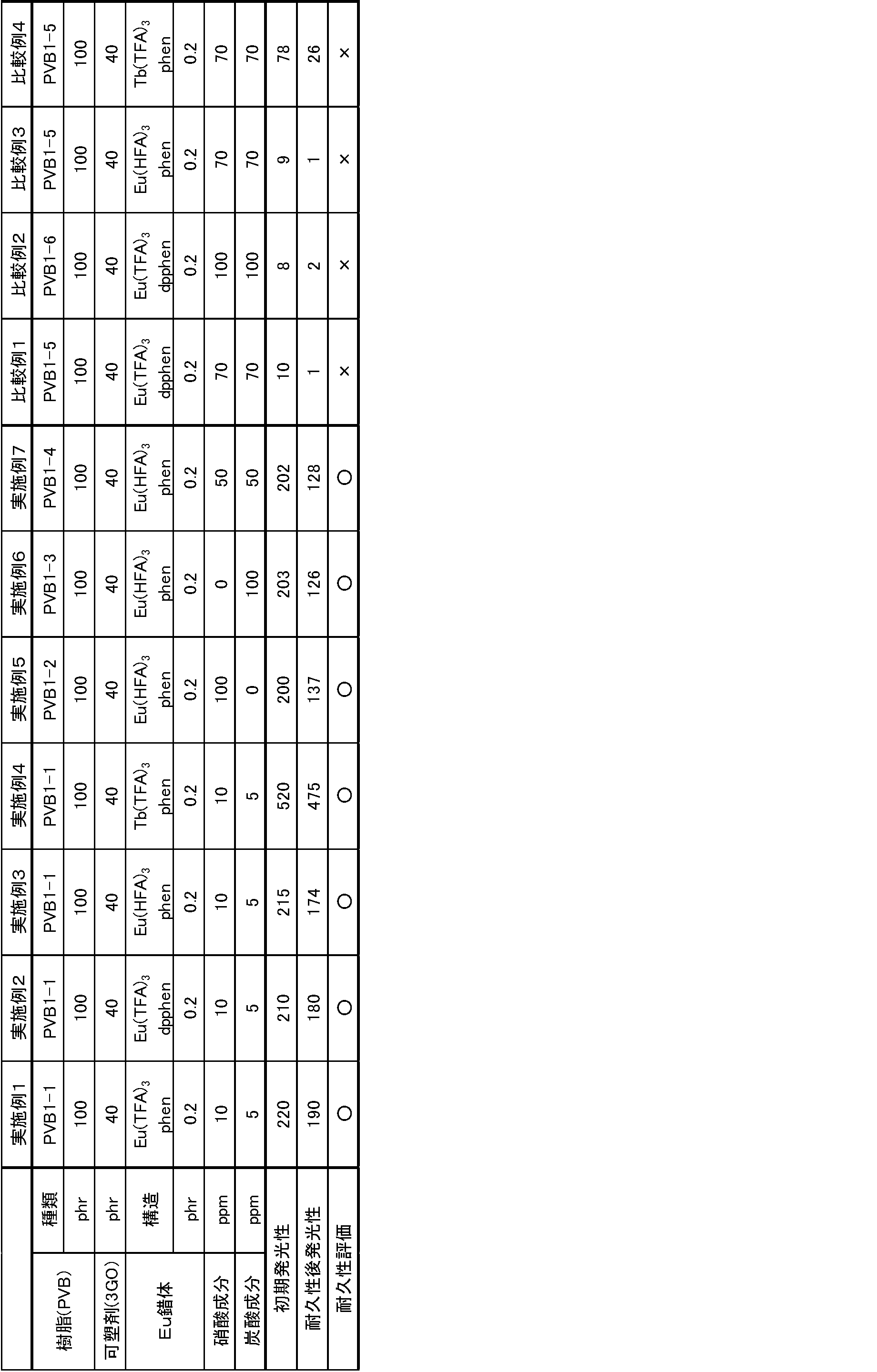
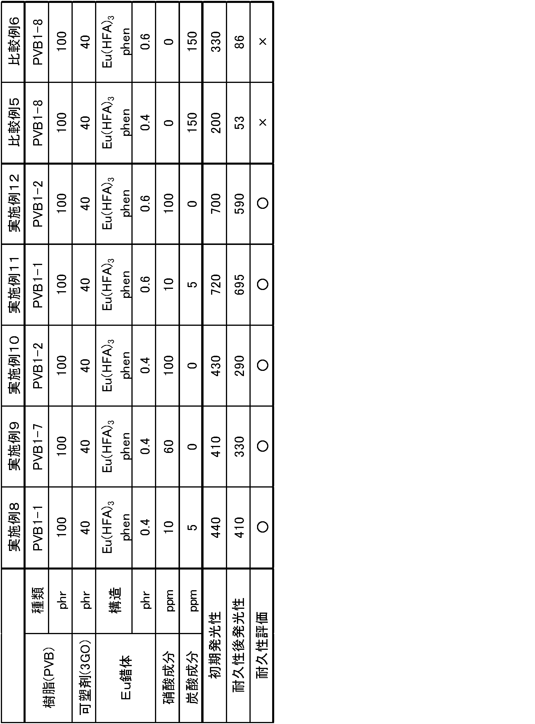


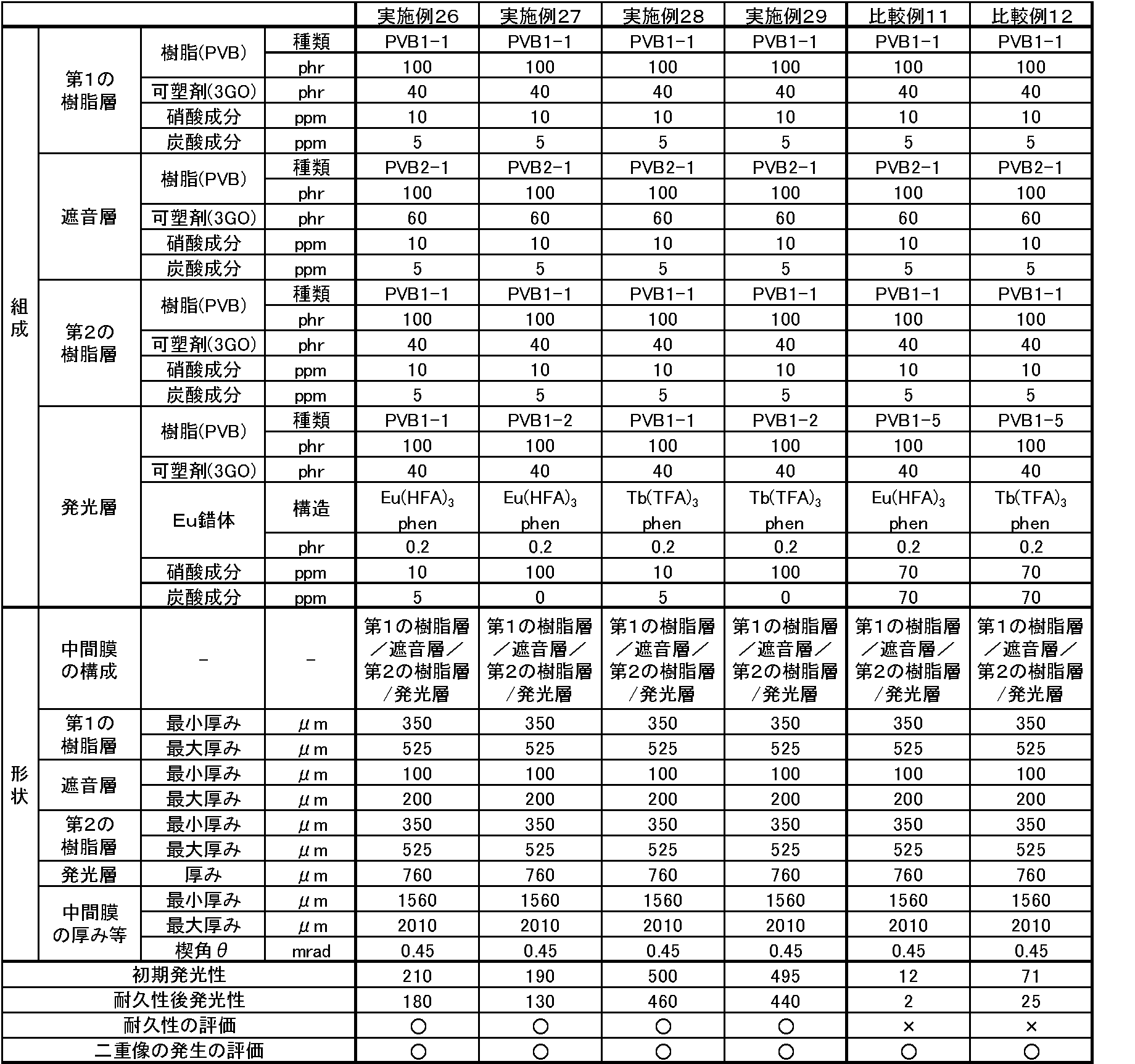

11 発光層
12 形状補助層
2 合わせガラス用中間膜
21 発光層
22 形状補助層
23 形状補助層
3 合わせガラス用中間膜
31 発光層
32 形状補助層
33 形状補助層 DESCRIPTION OF
Claims (6)
- ポリビニルアセタール樹脂と、発光粒子としてランタノイド錯体とを含有する発光層を有する合わせガラス用中間膜であって、
前記発光層に含まれる硝酸成分と炭酸成分との合計の含有量が100ppm以下である
ことを特徴とする合わせガラス用中間膜。 An interlayer film for laminated glass having a light emitting layer containing a polyvinyl acetal resin and a lanthanoid complex as light emitting particles,
An interlayer film for laminated glass, wherein the total content of a nitric acid component and a carbonic acid component contained in the light emitting layer is 100 ppm or less. - 発光層に含まれる硝酸成分と炭酸成分との合計の含有量が50ppm以下であることを特徴とする請求項1記載の合わせガラス用中間膜。 The interlayer film for laminated glass according to claim 1, wherein the total content of the nitric acid component and the carbonic acid component contained in the light emitting layer is 50 ppm or less.
- ランタノイド錯体は、ハロゲン原子を含む二座配位子を有するランタノイド錯体又はハロゲン原子を含む三座配位子を有するランタノイド錯体であることを特徴とする請求項1又は2記載の合わせガラス用中間膜。 The interlayer film for laminated glass according to claim 1 or 2, wherein the lanthanoid complex is a lanthanoid complex having a bidentate ligand containing a halogen atom or a lanthanoid complex having a tridentate ligand containing a halogen atom. .
- ランタノイド錯体は、ハロゲン原子を含みアセチルアセトン骨格を有する二座配位子を有するランタノイド錯体であることを特徴とする請求項1又は2記載の合わせガラス用中間膜。 The interlayer film for laminated glass according to claim 1 or 2, wherein the lanthanoid complex is a lanthanoid complex having a bidentate ligand containing a halogen atom and having an acetylacetone skeleton.
- ハロゲン原子は、フッ素原子であることを特徴とする請求項3又は4記載の合わせガラス用中間膜。 The interlayer film for laminated glass according to claim 3 or 4, wherein the halogen atom is a fluorine atom.
- 請求項1、2、3、4又は5記載の合わせガラス用中間膜が、2枚の透明板の間に積層されていることを特徴とする合わせガラス。 A laminated glass, wherein the interlayer film for laminated glass according to claim 1, 2, 3, 4 or 5 is laminated between two transparent plates.
Priority Applications (12)
| Application Number | Priority Date | Filing Date | Title |
|---|---|---|---|
| EP15826313.7A EP3192776B1 (en) | 2014-08-01 | 2015-08-03 | Intermediate film for laminated glass, and laminated glass |
| BR112017001076A BR112017001076A2 (en) | 2014-08-01 | 2015-08-03 | intermediate film for laminated glass, and laminated glass |
| RU2017106170A RU2681154C2 (en) | 2014-08-01 | 2015-08-03 | Intermediate film for laminated glass and laminated glass |
| AU2015297376A AU2015297376B2 (en) | 2014-08-01 | 2015-08-03 | Intermediate film for laminated glass, and laminated glass |
| CA2951224A CA2951224A1 (en) | 2014-08-01 | 2015-08-03 | Intermediate film for laminated glass, and laminated glass |
| MX2017000881A MX2017000881A (en) | 2014-08-01 | 2015-08-03 | Intermediate film for laminated glass, and laminated glass. |
| JP2015542091A JP5973083B2 (en) | 2014-08-01 | 2015-08-03 | Laminated glass interlayer film and laminated glass |
| CN201580040638.0A CN106573836B (en) | 2014-08-01 | 2015-08-03 | Intermediate film for laminated glasses and laminated glass |
| KR1020167026673A KR20170038756A (en) | 2014-08-01 | 2015-08-03 | Intermediate film for laminated glass, and laminated glass |
| US15/316,274 US10195824B2 (en) | 2014-08-01 | 2015-08-03 | Intermediate film for laminated glass, and laminated glass |
| ZA2016/08606A ZA201608606B (en) | 2014-08-01 | 2016-12-13 | Intermediate film for laminated glass, and laminated glass |
| US16/217,427 US20190111663A1 (en) | 2014-08-01 | 2018-12-12 | Intermediate film for laminated glass, and laminated glass |
Applications Claiming Priority (2)
| Application Number | Priority Date | Filing Date | Title |
|---|---|---|---|
| JP2014-158223 | 2014-08-01 | ||
| JP2014158223 | 2014-08-01 |
Related Child Applications (2)
| Application Number | Title | Priority Date | Filing Date |
|---|---|---|---|
| US15/316,274 A-371-Of-International US10195824B2 (en) | 2014-08-01 | 2015-08-03 | Intermediate film for laminated glass, and laminated glass |
| US16/217,427 Division US20190111663A1 (en) | 2014-08-01 | 2018-12-12 | Intermediate film for laminated glass, and laminated glass |
Publications (1)
| Publication Number | Publication Date |
|---|---|
| WO2016017824A1 true WO2016017824A1 (en) | 2016-02-04 |
Family
ID=55217718
Family Applications (1)
| Application Number | Title | Priority Date | Filing Date |
|---|---|---|---|
| PCT/JP2015/072003 WO2016017824A1 (en) | 2014-08-01 | 2015-08-03 | Intermediate film for laminated glass, and laminated glass |
Country Status (12)
| Country | Link |
|---|---|
| US (2) | US10195824B2 (en) |
| EP (1) | EP3192776B1 (en) |
| JP (2) | JP5973083B2 (en) |
| KR (1) | KR20170038756A (en) |
| CN (1) | CN106573836B (en) |
| AU (1) | AU2015297376B2 (en) |
| BR (1) | BR112017001076A2 (en) |
| CA (1) | CA2951224A1 (en) |
| MX (1) | MX2017000881A (en) |
| RU (1) | RU2681154C2 (en) |
| WO (1) | WO2016017824A1 (en) |
| ZA (1) | ZA201608606B (en) |
Families Citing this family (8)
| Publication number | Priority date | Publication date | Assignee | Title |
|---|---|---|---|---|
| US10562276B2 (en) | 2014-09-29 | 2020-02-18 | Sekisui Chemical Co., Ltd. | Interlayer film for laminated glass, and laminated glass |
| WO2016104592A1 (en) * | 2014-12-24 | 2016-06-30 | 積水化学工業株式会社 | Display device, interlayer film for laminated glass, and laminated glass |
| WO2018181418A1 (en) * | 2017-03-28 | 2018-10-04 | 積水化学工業株式会社 | Intermediate film for laminated glass, roll body, and laminated glass |
| MX2019011054A (en) * | 2017-03-30 | 2019-10-30 | Sekisui Chemical Co Ltd | Intermediate film for laminated glasses, and laminated glass. |
| KR102049495B1 (en) * | 2017-03-30 | 2019-11-28 | 세키스이가가쿠 고교가부시키가이샤 | Interlayer and Laminated Glass for Laminated Glass |
| MX2020004618A (en) * | 2017-12-28 | 2020-08-06 | Sekisui Chemical Co Ltd | Empty |
| JP2022031577A (en) * | 2018-11-30 | 2022-02-21 | 昭和電工マテリアルズ株式会社 | Film material for intermediate film of laminated glass, and laminated glass |
| JP2022033063A (en) * | 2018-11-30 | 2022-02-28 | 昭和電工マテリアルズ株式会社 | Resin material for intermediate film of glass laminate, film material for intermediate film of glass laminate, and glass laminate |
Citations (3)
| Publication number | Priority date | Publication date | Assignee | Title |
|---|---|---|---|---|
| JP5503089B1 (en) * | 2012-09-28 | 2014-05-28 | 積水化学工業株式会社 | Laminated glass interlayer film and laminated glass |
| WO2015046541A1 (en) * | 2013-09-27 | 2015-04-02 | 積水化学工業株式会社 | Intermediate film for laminated glass, and laminated glass |
| JP2015147725A (en) * | 2014-02-05 | 2015-08-20 | クラレイ ユーロップ ゲゼルシャフト ミット ベシュレンクテル ハフツングKuraray Europe GmbH | Method for producing laminated glass laminates from layered structure having plasticizer-containing polyvinyl acetal sheet and polyvinyl acetal sheet with low plasticizer content |
Family Cites Families (15)
| Publication number | Priority date | Publication date | Assignee | Title |
|---|---|---|---|---|
| MX171971B (en) | 1989-10-16 | 1993-11-24 | Libbey Owens Ford Co | DISPLAY PANEL FOR A VEHICLE WINDSHIELD |
| RU2261890C2 (en) * | 2003-11-21 | 2005-10-10 | Самсунг Электроникс Ко., Лтд. | Electrroluminescent polymeric nanocomposite material |
| JP4767177B2 (en) * | 2005-01-18 | 2011-09-07 | 株式会社ホプニック研究所 | Interlayer film for laminated safety glass with antiglare function and new neodymium compound |
| WO2006122305A2 (en) | 2005-05-11 | 2006-11-16 | E. I. Du Pont De Nemours And Company | Polymeric interlayers having a wedge profile |
| US8257843B2 (en) * | 2007-10-12 | 2012-09-04 | Sekisui Chemical Co., Ltd. | Interlayer for laminated glass and laminated glass |
| DE102009044181A1 (en) * | 2009-10-05 | 2011-04-07 | Saint-Gobain Sekurit Deutschland Gmbh & Co. Kg | Laminated glass as head-up display |
| EP2554578B1 (en) * | 2010-03-31 | 2018-11-21 | Kuraray Co., Ltd. | Polyvinyl acetal film and uses thereof |
| EP2409833A1 (en) * | 2010-07-23 | 2012-01-25 | Saint-Gobain Glass France | Laminated glazing for head-up display |
| FR2968240B1 (en) * | 2010-12-03 | 2012-12-14 | Saint Gobain | LAMINATED GLAZING FOR HIGH HEAD VISUALIZATION SYSTEM |
| EA026772B1 (en) * | 2011-04-15 | 2017-05-31 | Сэн-Гобэн Гласс Франс | Method for producing a film having luminescent particles |
| JP6192281B2 (en) | 2011-12-12 | 2017-09-06 | 積水化学工業株式会社 | Luminescent sheet, interlayer film for laminated glass and laminated glass |
| FR2985042B1 (en) | 2011-12-22 | 2014-01-17 | Saint Gobain | DEVICE FOR VISUALIZING AN IMAGE ON A SHEET SUPPORT |
| EP2905815A4 (en) * | 2012-10-03 | 2016-06-22 | Bridgestone Corp | Sealing film for solar cells and solar cell using same |
| US10424682B2 (en) * | 2013-11-04 | 2019-09-24 | Dow Global Technologies Llc | Multilayer down-converting encapsulant films and electronic devices including the same |
| JP6423958B2 (en) * | 2016-02-29 | 2018-11-14 | 積水化学工業株式会社 | Display device capable of displaying gradation pattern, automotive roof glass and building window glass |
-
2015
- 2015-08-03 CN CN201580040638.0A patent/CN106573836B/en active Active
- 2015-08-03 US US15/316,274 patent/US10195824B2/en active Active
- 2015-08-03 WO PCT/JP2015/072003 patent/WO2016017824A1/en active Application Filing
- 2015-08-03 BR BR112017001076A patent/BR112017001076A2/en not_active Application Discontinuation
- 2015-08-03 JP JP2015542091A patent/JP5973083B2/en active Active
- 2015-08-03 RU RU2017106170A patent/RU2681154C2/en active
- 2015-08-03 KR KR1020167026673A patent/KR20170038756A/en not_active Application Discontinuation
- 2015-08-03 CA CA2951224A patent/CA2951224A1/en not_active Abandoned
- 2015-08-03 EP EP15826313.7A patent/EP3192776B1/en active Active
- 2015-08-03 MX MX2017000881A patent/MX2017000881A/en active IP Right Grant
- 2015-08-03 AU AU2015297376A patent/AU2015297376B2/en not_active Ceased
-
2016
- 2016-07-12 JP JP2016137586A patent/JP2016216357A/en active Pending
- 2016-12-13 ZA ZA2016/08606A patent/ZA201608606B/en unknown
-
2018
- 2018-12-12 US US16/217,427 patent/US20190111663A1/en not_active Abandoned
Patent Citations (3)
| Publication number | Priority date | Publication date | Assignee | Title |
|---|---|---|---|---|
| JP5503089B1 (en) * | 2012-09-28 | 2014-05-28 | 積水化学工業株式会社 | Laminated glass interlayer film and laminated glass |
| WO2015046541A1 (en) * | 2013-09-27 | 2015-04-02 | 積水化学工業株式会社 | Intermediate film for laminated glass, and laminated glass |
| JP2015147725A (en) * | 2014-02-05 | 2015-08-20 | クラレイ ユーロップ ゲゼルシャフト ミット ベシュレンクテル ハフツングKuraray Europe GmbH | Method for producing laminated glass laminates from layered structure having plasticizer-containing polyvinyl acetal sheet and polyvinyl acetal sheet with low plasticizer content |
Also Published As
| Publication number | Publication date |
|---|---|
| CN106573836A (en) | 2017-04-19 |
| JPWO2016017824A1 (en) | 2017-04-27 |
| US20190111663A1 (en) | 2019-04-18 |
| RU2017106170A (en) | 2018-09-03 |
| EP3192776B1 (en) | 2019-12-04 |
| ZA201608606B (en) | 2018-05-30 |
| US20170197381A1 (en) | 2017-07-13 |
| AU2015297376B2 (en) | 2018-08-02 |
| JP5973083B2 (en) | 2016-08-23 |
| CN106573836B (en) | 2019-08-30 |
| EP3192776A4 (en) | 2018-03-07 |
| JP2016216357A (en) | 2016-12-22 |
| EP3192776A1 (en) | 2017-07-19 |
| MX2017000881A (en) | 2017-05-01 |
| US10195824B2 (en) | 2019-02-05 |
| BR112017001076A2 (en) | 2017-11-21 |
| RU2681154C2 (en) | 2019-03-04 |
| AU2015297376A1 (en) | 2016-12-15 |
| KR20170038756A (en) | 2017-04-07 |
| RU2017106170A3 (en) | 2019-01-17 |
| CA2951224A1 (en) | 2016-02-04 |
Similar Documents
| Publication | Publication Date | Title |
|---|---|---|
| JP5973082B2 (en) | Laminated glass interlayer film and laminated glass | |
| JP5973083B2 (en) | Laminated glass interlayer film and laminated glass | |
| JP6595963B2 (en) | Display device, interlayer film for laminated glass and laminated glass | |
| KR102544849B1 (en) | Emissive displays, interlayers for laminated glass, laminated glass, and emissive display systems | |
| JP7164432B2 (en) | Emissive display system and head-up display | |
| JP6235759B1 (en) | Luminescent sheet, interlayer film for laminated glass, and laminated glass | |
| WO2017150555A1 (en) | Display device capable of displaying gradation pattern, glass for automobile roof, and window glass for building | |
| JP2017141131A (en) | Luminescent sheet, intermediate film for laminated glass, and laminated glass |
Legal Events
| Date | Code | Title | Description |
|---|---|---|---|
| ENP | Entry into the national phase |
Ref document number: 2015542091 Country of ref document: JP Kind code of ref document: A |
|
| 121 | Ep: the epo has been informed by wipo that ep was designated in this application |
Ref document number: 15826313 Country of ref document: EP Kind code of ref document: A1 |
|
| ENP | Entry into the national phase |
Ref document number: 20167026673 Country of ref document: KR Kind code of ref document: A |
|
| ENP | Entry into the national phase |
Ref document number: 2951224 Country of ref document: CA |
|
| WWE | Wipo information: entry into national phase |
Ref document number: 15316274 Country of ref document: US |
|
| ENP | Entry into the national phase |
Ref document number: 2015297376 Country of ref document: AU Date of ref document: 20150803 Kind code of ref document: A |
|
| WWE | Wipo information: entry into national phase |
Ref document number: MX/A/2017/000881 Country of ref document: MX |
|
| REG | Reference to national code |
Ref country code: BR Ref legal event code: B01A Ref document number: 112017001076 Country of ref document: BR |
|
| NENP | Non-entry into the national phase |
Ref country code: DE |
|
| REEP | Request for entry into the european phase |
Ref document number: 2015826313 Country of ref document: EP |
|
| WWE | Wipo information: entry into national phase |
Ref document number: 2015826313 Country of ref document: EP |
|
| ENP | Entry into the national phase |
Ref document number: 2017106170 Country of ref document: RU Kind code of ref document: A |
|
| ENP | Entry into the national phase |
Ref document number: 112017001076 Country of ref document: BR Kind code of ref document: A2 Effective date: 20170118 |