WO2016013093A1 - 無線通信装置、無線通信制御方法及び無線通信制御プログラム - Google Patents
無線通信装置、無線通信制御方法及び無線通信制御プログラム Download PDFInfo
- Publication number
- WO2016013093A1 WO2016013093A1 PCT/JP2014/069626 JP2014069626W WO2016013093A1 WO 2016013093 A1 WO2016013093 A1 WO 2016013093A1 JP 2014069626 W JP2014069626 W JP 2014069626W WO 2016013093 A1 WO2016013093 A1 WO 2016013093A1
- Authority
- WO
- WIPO (PCT)
- Prior art keywords
- frequency range
- transmission
- signal
- band side
- reception
- Prior art date
- Legal status (The legal status is an assumption and is not a legal conclusion. Google has not performed a legal analysis and makes no representation as to the accuracy of the status listed.)
- Ceased
Links
Images





Classifications
-
- H—ELECTRICITY
- H04—ELECTRIC COMMUNICATION TECHNIQUE
- H04W—WIRELESS COMMUNICATION NETWORKS
- H04W72/00—Local resource management
- H04W72/04—Wireless resource allocation
Definitions
- the present invention relates to a wireless communication device, a wireless communication control method, and a wireless communication control program.
- wireless communication devices such as mobile stations adopting the LTE (Long Term Evolution) -Advanced method (3GPP TS36.101 Release 10) have realized higher-speed communication while maintaining compatibility with the LTE method.
- LTE Long Term Evolution
- a carrier aggregation CA: Carrier
- LB LowBand
- HB HighBand
- Aggregation is known.
- the mobile station can realize high-speed communication by using LB and HB simultaneously during CA communication to distribute and transmit data.
- FIG. 8 is an explanatory diagram showing an example of the frequency range of each signal related to the mobile station during CA communication.
- Band8 transmission (Band8-Tx), Band8 reception (Band8-Rx), Band3 transmission (Band3-Tx), and Band3 reception (Band3-Rx) of the mobile station are illustrated.
- the second harmonic (Band8-2Tx) which is a harmonic component of Band8 transmission, is illustrated.
- Band8-Tx has a frequency range of, for example, 880 MHz to 915 MHz
- Band8-Rx has a frequency range of, for example, 925 MHz to 960 MHz
- Band3-Tx has a frequency range of, for example, 1710 MHz to 1785 MHz.
- Band3-Rx has a frequency range of 1805 MHz to 1880 MHz, for example.
- the second harmonic of Band8-Tx (Band8-2Tx) has a frequency range of 1760 MHz to 1830 MHz, for example, and thus interferes with 1805 MHz to 1830 MHz, which is a part of the Band3-Rx frequency range.
- the second harmonic of Band 8 transmission interferes with Band 3 reception, which is the HB reception band, and causes deterioration in reception sensitivity of Band 3 reception.
- the mobile station employs an MPR (Maximum Power Reduction) function for attenuating the maximum output level of the transmission signal, and there is a technique for avoiding adjacent channel interference and spurious radiation during CA communication, for example.
- MPR Maximum Power Reduction
- the maximum output level of a transmission signal is attenuated in accordance with an instruction from a base station that accommodates the mobile station.
- the base station determines whether or not MPR can be activated based on information such as the number of transmission carriers of the mobile station, transmission frequency, modulation scheme, and bandwidth.
- the MPR function to attenuate the maximum output level of the LB transmission signal, the influence of the LB transmission signal on the HB reception signal can be avoided.
- the maximum output level of the LB transmission signal gradually decreases and communication is performed. The area becomes narrow, and the communication efficiency decreases.
- the base station determines whether MPR activation is possible for each mobile station to be accommodated based on information such as the number of transmission carriers, transmission frequency, modulation scheme, and bandwidth of the mobile station. Depending on the number, the processing burden is large.
- An object of one aspect of the present invention is to provide a wireless communication device, a wireless communication control method, and a wireless communication control program that can avoid interference with a received signal on a high band side due to harmonic components of a transmission signal on a low band side.
- it has an acquisition unit, a calculation unit, a determination unit, and a control unit.
- An acquisition part acquires the parameter of a communication signal among the communication signals used at the time of carrier aggregation communication.
- the calculation unit calculates the frequency range of the harmonic component of the transmission signal on the low band side and the frequency range of the reception signal on the high band side of the communication signal based on the acquired parameters.
- the determination unit determines whether or not a frequency range of a harmonic component of the transmission signal on the low band side interferes with a frequency range of the reception signal on the high band side.
- the control unit controls the transmission signal on the low band side when the frequency range of the harmonic component of the transmission signal on the low band side interferes with the frequency range of the reception signal on the high band side.
- FIG. 1 is an explanatory diagram of an example of a mobile station according to the first embodiment.
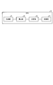
- FIG. 2 is a block diagram illustrating an example of a functional configuration of the CPU.
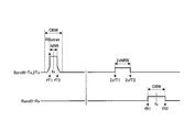
- FIG. 3A is an explanatory diagram illustrating an example of a frequency range of Band8 transmission (Band8-Tx) and Band3 reception (Band3-Rx) during CA communication.
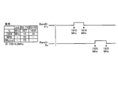
- FIG. 3B is an explanatory diagram showing an example of the frequency range of the second harmonic (Band8-2Tx) of Band8 transmission (Band8-Tx) and Band3 reception (Band3-Rx) without signal interference.
- FIG. 1 is an explanatory diagram of an example of a mobile station according to the first embodiment.
- FIG. 2 is a block diagram illustrating an example of a functional configuration of the CPU.
- FIG. 3A is an explanatory diagram illustrating an example of a frequency range of Band8 transmission (Band8-Tx) and Band3 reception (Band3-Rx) during CA communication.
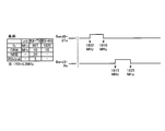
- FIG. 3C is an explanatory diagram illustrating an example of a frequency range of a second harmonic (Band8-2Tx) and Band3 reception (Band3-Rx) of Band8 transmission (Band8-Tx) in a signal interference state.
- FIG. 3D is an explanatory diagram illustrating an example of a frequency range of the second harmonic (Band8-2Tx) of Band8 transmission and Band3 reception (Band3-Rx) after execution of the interference avoidance process.
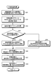
- FIG. 4 is a flowchart showing an example of the processing operation of the CPU of the mobile station involved in the monitoring process.
- FIG. 5 is a flowchart illustrating an example of processing operations of the mobile station and the base station related to the interference avoidance process.
- FIG. 6 is an explanatory diagram of an example of a mobile station according to the second embodiment.
- FIG. 7 is an explanatory diagram illustrating an example of a wireless communication device that executes a wireless communication control program.
- FIG. 8 is an explanatory diagram showing an example of the frequency range of each signal related to the mobile station during CA communication.
- FIG. 1 is an explanatory diagram illustrating an example of a mobile station according to the first embodiment.
- the mobile station 1 shown in FIG. 1 is a wireless communication apparatus such as a smartphone that employs the LTE-Advanced method and is connected to the base station 2 wirelessly.
- the mobile station 1 shown in FIG. 1 includes a wireless unit 11, a MODEM 12, a storage unit 13, and a CPU (Central Processing Unit) 14.
- the radio unit 11 includes a first radio unit 11A, a second radio unit 11B, a third radio unit 11C, and a fourth radio unit 11D.
- the first radio unit 11A is a main radio unit of Band 8 that manages radio communication of LB communication, for example, Band 8 communication (transmission and reception).
- the first radio unit 11A includes a first antenna 21A, a DUP (Duplexer) 22A, a CUP (Cupler) 23A, a DET (Detector) 24A, and a PA (Power Amplifier) 25A.
- the first antenna 21A is, for example, a Band8 main antenna that transmits and receives Band8 communication radio signals.
- the DUP 22A is a demultiplexing unit that demultiplexes the reception signal and transmission signal of Band8 communication.
- the CUP 23A is a distribution unit that distributes a part of the wireless signal of Band8 communication.
- the DET 24A is a detection unit that detects the radio level of the radio signal distributed by the CUP 23A.
- the PA 25A is an amplifier that adjusts the output level of a transmission signal for Band 8 transmission.
- the second radio unit 11B includes a second antenna 21B, a DUP 22B, a CUP 23B, a DET 24B, and a PA 25B.
- the second radio unit 11B is a main radio unit of Band 3 that manages radio communication of HB communication, for example, Band 3 communication (transmission and reception).
- the second antenna 21B is, for example, a Band3 main antenna that transmits and receives a wireless signal of Band3 communication.
- the DUP 22B is a demultiplexing unit that demultiplexes the reception signal and transmission signal of Band3 communication.
- the CUP 23B is a distribution unit that distributes a part of the wireless signal of Band3 communication.
- the DET 24B is a detection unit that detects the radio level of the radio signal distributed by the CUP 23B.
- the PA 25B is an amplifier that adjusts the output level of the transmission signal of Band 3 transmission.
- the third wireless unit 11C includes a third antenna 21C and a FIL (Filter) 26C.
- the third radio unit 11C is, for example, a Band 8 reception sub radio unit.
- the third antenna 21C is, for example, a Band 8 sub-reception antenna that receives a reception signal of Band 8 reception.
- the FIL 26C is a filter that extracts, for example, Band 8 reception data from which noise components have been removed from a Band 8 reception reception signal.
- the fourth wireless unit 11D includes a fourth antenna 21D and a FIL 26D.
- the fourth radio unit 11D is, for example, a sub-radio unit for receiving Band3.
- the fourth antenna 21D is, for example, a Band 3 sub reception antenna that receives a reception signal of Band 3 reception.
- the FIL 26D is a filter that extracts, for example, Band3 reception data from which noise components have been removed from a Band3 reception signal.
- the MODEM 12 is a communication control unit that controls the wireless communication of the wireless unit 11.
- the MODEM 12 controls the PA 25A in the first radio unit 11A so as to stably output the output level of Band8 transmission based on the radio level detected by the DET 24A in the first radio unit 11A.
- the MODEM 12 controls the PA 25B in the second radio unit 11B so as to stably output the output level of Band3 transmission based on the radio level detected by the DET 24B in the second radio unit 11B.
- the MODEM 12 includes a Band8-Tx unit 31, a Band3-Tx unit 32, a Band8-main Rx unit 33, a Band3-main Rx unit 34, a Band8-sub Rx unit 35, and a Band3-sub Rx unit 36. .
- the Band8-Tx unit 31 is a part that is connected to the PA 25A in the first radio unit 11A and modulates and outputs a transmission signal of Band8 transmission.
- the Band3-Tx unit 32 is a part that is connected to the PA 25B in the second radio unit 11B and modulates and outputs a transmission signal for Band3 transmission.
- the Band8-main Rx unit 33 is a part that is connected to the DUP 22A in the first radio unit 11A and demodulates and outputs the received signal on the main side of Band8 reception.
- the Band3-main Rx unit 34 is connected to the DUP 22B in the second radio unit 11B and demodulates and outputs the received signal on the main side of Band3 reception.
- the Band8-sub Rx unit 35 is a part that is connected to the FIL 26C in the third radio unit 11C and demodulates and outputs a reception signal on the sub side of Band8 reception.
- the Band3-sub Rx unit 36 is a part that is connected to the FIL 26D in the fourth radio unit 11D and demodulates and outputs the reception signal on the sub-side of Band3 reception.
- the Band3-main Rx unit 34 and the Band3-sub Rx unit 36 constitute Band3 reception diversity
- the Band8-main Rx unit 33 and Band8-sub Rx unit 35 constitute Band8 reception diversity.
- the storage unit 13 is an area for storing various information.
- the CPU 14 is a part that controls the entire mobile station 1.
- the CPU 14 reads the wireless communication control program stored in the storage unit 13 and configures various processes as functions based on the read wireless communication control program.
- the CPU 14 operates using the acquisition unit 41, the calculation unit 42, the determination unit 43, and the control unit 44 as functions.
- the acquisition unit 41 acquires a wireless parameter of Band8 transmission that is an LB transmission signal through the MODEM 12.
- Band 8 transmission radio parameters include the frequency channel (fc) of the transmission signal of Band 8 transmission, the channel bandwidth (CBW) of the transmission signal, the number of resource blocks (NRB) of the transmission signal, and the start position number of the transmission signal.
- fc frequency channel
- CBW channel bandwidth
- NRB resource blocks
- 2 ⁇ NRB corresponds to the number of resource blocks of the second harmonic of Band8 transmission, and has a frequency range of 2 ⁇ fT1 to 2 ⁇ fT2.
- the acquisition unit 41 acquires wireless parameters for Band3 reception, which is an HB reception signal, through the MODEM 12.
- the Band3 reception radio parameters include the frequency channel fc of the reception signal of Band3 reception and the channel bandwidth (CBW) of the reception signal.
- FIG. 3A is an explanatory diagram showing an example of the frequency range of Band 8 transmission (Band 8-Tx) and Band 3 reception (Band 3-Rx) during CA communication.
- the calculation unit 42 calculates the frequency range fTx of the second harmonic of Band 8 transmission on the LB side and the frequency range fRx of Band 3 reception on the HB side.
- the frequency range fTx (MHz) of the second harmonic is calculated. Note that n corresponds to the harmonic order, and the coefficient 0.2 corresponds to the bandwidth per resource block (RB).
- the calculation unit 42 calculates the frequency range fRx of Band 3 reception on the HB side based on the radio parameters of Band 3 reception.
- the determination unit 43 compares the frequency range fTx of the second harmonic of Band8 transmission with the frequency range fRx of Band3 reception, and determines whether or not the frequency range fTx interferes with the frequency range fRx.
- FIG. 3B is an explanatory diagram showing an example of the frequency range of the second harmonic (Band8-2Tx) of Band8 transmission (Band8-Tx) and Band3 reception (Band3-Rx) without signal interference.
- the frequency range fTx of Band8-2Tx of the second harmonic of Band8 transmission is set to 1810 MHz to 1818 MHz
- the frequency range fRx of Band3 reception is set to 1825 MHz to 1835 MHz.
- 3C is an explanatory diagram illustrating an example of a frequency range of a second harmonic (Band8-2Tx) and Band3 reception (Band3-Rx) of Band8 transmission (Band8-Tx) in a signal interference state.
- the frequency range fTx of Band8-2Tx of the second harmonic of Band8 transmission is set to 1810 MHz to 1818 MHz
- the frequency range fRx of Band3 reception is set to 1815 MHz to 1825 MHz.
- the frequency range fTx of the second harmonic of Band 8 transmission interferes with the frequency range fRx of Band 3 reception.
- the control unit 44 determines whether or not the transmission power value, which is the output level of Band8 transmission, exceeds a predetermined threshold when the frequency range fTx interferes with the frequency range fRx.
- the predetermined threshold corresponds to the transmission power value (LB-Pcmax) of Band 8 transmission in which the frequency range fTx of the second harmonic of Band 8 transmission does not interfere with the frequency range fRx of Band 3 reception.
- the predetermined threshold is set after verification in advance.
- the control unit 44 sets parameters of the transmission signal of Band 8 transmission so that the frequency range fTx of the second harmonic of Band 8 transmission does not interfere with the frequency range fRx of Band 3 reception. Adjust.
- the control unit 44 calculates RB limit values (NRBc and RBSc) that are radio parameters of a transmission signal of Band8 transmission so as not to interfere with the frequency range fRx of Band3 reception.
- control unit 44 transmits an alarm including the calculated NRBc, RBSc, and Pcmax to the base station 2 on the uplink.
- the base station 2 When the base station 2 receives an alarm from the mobile station 1, the base station 2 determines whether or not the NRBc and RBSc in the alarm are operable. When the NRBc and RBSc in the alarm can be operated, the base station 2 transmits control information including the RB limit values of the NRBc and RBSc to the mobile station 1 to be controlled.
- the control unit 44 in the mobile station 1 receives the control information from the base station 2, the control unit 44 controls the transmission signal of Band8 transmission by adjusting the radio parameter of Band8 transmission according to the NRBc and RBSc in the control information.
- the frequency range fTx of the second harmonic of Band8 transmission is adjusted so as not to interfere with the frequency range fRx of Band3 reception.
- the base station 2 moves the control information including the update contents so that the output level of the Band8 transmission is equal to or lower than a predetermined threshold (LB-Pmax). Transmit to station 1.
- the control unit 44 in the mobile station 1 adjusts the output level of Band8 transmission according to the update content in the control information and controls the transmission signal of Band8 transmission.
- the frequency range fTx of the second harmonic of Band8 transmission is adjusted so as not to interfere with the frequency range fRx of Band3 reception.
- FIG. 4 is a flowchart showing an example of the processing operation of the CPU 14 of the mobile station 1 related to the monitoring process.
- the monitoring process shown in FIG. 4 is a process for monitoring the start timing of the interference avoidance process based on the frequency range fTx of the second harmonic of Band8 transmission, the frequency range fRx of Band3 reception, and the output level of Band8 transmission.
- the acquisition unit 41 in the CPU 14 acquires wireless parameters for Band8 transmission (LB signal) and Band3 reception (Step S11).
- the radio parameters for Band 8 transmission include a frequency channel (fc), a channel bandwidth (CBW), the number of resource blocks (NRB), and a start position number (RBS) related to a transmission signal for Band 8 transmission.
- the radio parameter for Band3 reception includes a frequency channel (fc) and a channel bandwidth (CBW) related to a reception signal for Band3 reception.
- the calculation unit 42 in the CPU 14 calculates the frequency range fTx of the second harmonic of Band 8 transmission based on the acquired wireless parameter of Band 8 transmission (LB signal). Further, the calculation unit 42 calculates the frequency range fRx of Band3 reception based on the acquired wireless parameter of Band3 reception (HB signal) (step S12).
- the determination unit 43 in the CPU 14 compares the frequency range fTx of the second harmonic of Band 8 transmission with the frequency range fRx of Band 3 reception. Then, the determination unit 43 determines whether or not the frequency range fTx of the second harmonic of Band8 transmission interferes with the frequency range fRx of Band3 reception (Step S13). As shown in FIG. 3C, when the frequency range fTx of the second harmonic of Band8 transmission interferes with the frequency range fRx of Band3 reception (step S13 positive), the control unit 44 in the CPU 14 transmits the transmission power value of Band8 transmission from MODEM12. Is acquired (step S14).
- the control unit 44 determines whether or not the transmission power value for Band 8 transmission is equal to or greater than a predetermined threshold (LB-Pcmax) (step S15).
- the predetermined threshold (LB-Pcmax) corresponds to the maximum transmission power value (LB-Pcmax) of Band8 transmission in which the frequency range fTx of the second harmonic of Band8 transmission does not interfere with the frequency range fRx of Band3 reception.
- the control unit 44 activates the interference avoidance process shown in FIG. 5 (Step S16) and performs the processing operation shown in FIG. finish.
- the determination unit 43 ends the processing operation illustrated in FIG.
- the control unit 44 ends the processing operation illustrated in FIG.
- the CPU 14 that executes the monitoring process calculates the frequency range fTx of the second harmonic of Band 8 transmission and the frequency range fRx of Band 3 reception based on the radio parameters of Band 8 transmission and Band 3 reception.
- the CPU 14 determines whether or not the frequency range fTx of the second harmonic of Band 8 transmission interferes with the frequency range fRx of Band 3 reception. As a result, the CPU 14 can recognize interference with the frequency range fRx of Band3 reception due to the frequency range fTx of the second harmonic of Band8 transmission.
- the CPU 14 When the frequency range fTx of the second harmonic of the Band 8 transmission interferes with the frequency range fRx of the Band 3 transmission and the transmission power value of the Band 8 transmission exceeds a predetermined threshold, the CPU 14 performs an interference avoidance process for controlling the Band 8 transmission. to start. As a result, the CPU 14 can start the interference avoidance process when the frequency range fTx of the second harmonic of Band8 transmission interferes with the frequency range fRx of Band3 reception and the output level of Band8 transmission exceeds a predetermined threshold.
- the Band3 reception frequency range fRx is calculated using the radio parameters of the Band3 reception signal.
- the Band3 reception frequency range may be acquired from the MODEM 12.
- FIG. 5 is a flowchart showing an example of processing operations of the mobile station 1 and the base station 2 related to interference avoidance processing.
- the interference avoidance process shown in FIG. 5 is a process for adjusting the radio parameter of Band8 transmission to avoid interference with the frequency range fRx of Band3 reception by the frequency range fTx of the second harmonic of Band8 transmission.
- the control unit 44 on the mobile station 1 side calculates the RB limit value for Band8 transmission in response to the start of the interference avoidance process in step S16 shown in FIG. 4 (step S21).
- the RB limit value corresponds to NRBc and RBSc for adjusting Band8 transmission so that the frequency range fTx of the second harmonic of Band8 transmission does not interfere with the frequency range fRx of Band3 reception.
- the control unit 44 notifies an alarm to the base station 2 (step S22).
- the alarm includes RB limit values (NRB and RBS) and LB-Pcmax.
- the base station 2 receives the alarm from the mobile station 1 (step S23), and determines whether the NRBc and RBSc that are the RB limit values in the alarm on the base station 2 side are operable (step S24). .
- the base station 2 checks whether the RB limit values NRBc and RBSc are capable of operating the entire radio system.
- the base station 2 updates the RB limit values (NRBc and RBSc) as Band8 transmission control information (Step S25).
- the base station 2 notifies the control information to the control target mobile station 1 (step S26).
- the mobile station 1 receives the control information from the base station 2 (step S27), controls Band8 transmission based on the RB limit value in the received control information (step S28), and ends the processing operation shown in FIG. To do.
- the mobile station 1 controls the Band8 transmission with the RB limit value, as shown in FIG. 3D, it is possible to avoid interference with the Band3 reception frequency range due to the second harmonic of the Band8 transmission.
- the base station 2 updates the transmission power value of Band8 transmission to be equal to or less than a predetermined threshold (LB-Pcmax) (Step S29). Further, the base station 2 proceeds to step S26 in order to notify the control information including the updated contents. As a result, since the mobile station 1 adjusts the output level of Band8 transmission with LB-Pcmax in the control information, interference with the frequency range of Band3 reception due to the second harmonic of Band8 transmission can be avoided.
- LB-Pcmax a predetermined threshold
- the mobile station 1 that executes the interference avoidance process calculates the RB limit value and notifies the base station 2 of an alarm including the RB limit value.
- the base station 2 determines whether or not the RB limit value is operable, and notifies the mobile station 1 of control information of the RB limit value when the RB limit value is operable.
- the mobile station 1 controls Band8 transmission according to the RB limit value of the control information. As a result, the mobile station 1 can adjust the Band8 transmission so that the frequency range fTx of the second harmonic of the Band8 transmission does not interfere with the frequency range fRx of the Band3 reception.
- the base station 2 controls the transmission power value of Band8 transmission so that the transmission power value of Band8 transmission is equal to or less than a predetermined threshold (LB-Pcmax).
- LB-Pcmax a predetermined threshold
- the mobile station 1 can adjust the transmission power of Band8 transmission so that the frequency range fTx of the second harmonic of Band8 transmission does not interfere with the frequency range fRx of Band3 reception.
- the mobile station 1 calculates the frequency range fTx of the second harmonic of Band 8 transmission and the frequency range fRx of Band 3 reception based on the radio parameters of Band 8 transmission and Band 3 reception. Furthermore, the mobile station 1 performs interference avoidance processing only when the frequency range fTx of the second harmonic of Band 8 transmission interferes with the frequency range fRx of Band 3 reception and the transmission power value of Band 8 transmission exceeds a predetermined threshold value. Execute. As a result, it is possible to minimize the activation of the interference avoidance process and avoid a situation in which the communication area is narrowed and the communication efficiency is lowered. In addition, a decrease in communication efficiency can be suppressed while avoiding interference with Band 3 reception due to harmonic components of Band 8 transmission.
- Example 1 when the frequency range fTx of the second harmonic of Band 8 transmission interferes with the frequency range fRx of Band 3 reception, Band 8 transmission is controlled so that the second harmonic does not interfere with Band 3 reception.
- Band 8 transmission is controlled so that the second harmonic does not interfere with Band 3 reception.
- interference with Band3 reception due to double harmonics can be avoided without using a linearity amplifier, harmonic suppression filter, or the like, so that an increase in the number of components and an increase in current can be suppressed.
- the RB limit value is used as the interference avoidance process, and the Band 8 transmission is adjusted so that the second harmonic of the Band 8 transmission does not interfere with the frequency range of the Band 3 reception.
- the embodiment in this case will be described below as Example 2.
- FIG. 6 is an explanatory diagram of an example of the mobile station 1A according to the second embodiment. Note that the same components as those of the mobile station 1 of the first embodiment are denoted by the same reference numerals, and the description of the overlapping configuration and operation is omitted.
- the mobile station 1A shown in FIG. 6 differs from the mobile station 1 shown in FIG. 1 in that a cancel signal is generated by the output signal of the second radio unit 11B, and the Band 8 of the first radio unit 11A is generated by the generated cancel signal. It is in the point provided with the cancellation part 50 which cancels the 2nd harmonic of transmission. Note that the Band3-Tx unit 32 of the second radio unit 11B generates an output signal when Band3 transmission is suspended.
- the cancel unit 50 includes a SW 51, a BPF (Band Pass Filter) 52, a level adjustment unit 53, a phase adjustment unit 54, and a CUP 55.
- the SW 51 is a part that switches and outputs an output signal from the Band3-Tx unit 32 between the PA 25B and the DUP 22B in the second radio unit 11B.
- the BPF 52 extracts a signal component corresponding to the second harmonic of Band8 transmission from the output signal that is the switching output of the SW51.
- the level adjustment unit 53 adjusts the level of the signal component extracted by the BPF 52 to the second harmonic level of Band 8 transmission.
- the phase conversion unit 54 converts the level-adjusted signal component into an opposite phase and generates a cancel signal.
- the CUP 55 cancels the second harmonic by superimposing a cancel signal on the second harmonic of Band8 transmission.
- the CPU 14 of the mobile station 1A activates the cancel unit 50 when the frequency range fTx of the second harmonic of Band8 transmission interferes with the frequency range fRx of Band3 reception and the transmission power value of Band8 transmission is equal to or greater than a predetermined threshold value.
- the second wireless unit 11B is in a state in which Band3 transmission is suspended.
- the cancellation unit 50 switches and inputs the output signal from the Band3-Tx unit 32 from the PA 25B through the SW 51.
- the BPF 52 extracts a signal component corresponding to the second harmonic of Band8 transmission from the output signal.
- the level adjustment unit 53 adjusts the level of the signal component extracted by the BPF 52 so that it becomes the level of the second harmonic of Band 8 transmission.
- the phase conversion unit 54 converts the level-adjusted signal component into an opposite phase and generates a cancel signal.
- the CUP 55 cancels the second harmonic of Band8 transmission in order to superimpose the cancel signal on the second harmonic of Band8 transmission.
- the mobile station 1A cancels the second harmonic of the Band8 transmission with the cancel signal, so that the conventional communication area becomes narrow while avoiding interference with the Band3 reception due to the second harmonic of the Band8 transmission. Therefore, it is possible to avoid a situation where the communication efficiency decreases.
- the second harmonic of Band8 transmission is canceled by the cancel signal generated from the output signal of the second radio unit 11B.
- the cancel signal generated from the output signal of the second radio unit 11B it is possible to avoid the influence on the Band3 reception due to the second harmonic of the Band8 transmission and to suppress the decrease in communication efficiency.
- the cancel signal is generated as an output signal of the Band3-Tx unit 32 of the second radio unit 11B.
- a generation unit that generates an output signal as a cancel signal is provided separately. May be.
- Band 8 transmission is exemplified as the transmission signal on the LB side and Band 3 reception is illustrated as the reception signal on the HB side.
- the present invention is not limited to these.
- the frequency range of the second harmonic of Band 8 transmission interferes with the frequency range of Band 3 reception is illustrated, but the frequency range of the second harmonic is not limited to the second harmonic, and the transmission side n-th harmonic.
- the present invention is also applicable when a wave interferes with the frequency range on the receiving side.
- each component of each part illustrated does not necessarily need to be physically configured as illustrated.
- the specific form of distribution / integration of each part is not limited to the one shown in the figure, and all or a part thereof may be functionally or physically distributed / integrated in arbitrary units according to various loads and usage conditions. Can be configured.
- each device is all or any part of it on a CPU (Central Processing Unit) (or a micro computer such as MPU (Micro Processing Unit) or MCU (Micro Controller Unit)). You may make it perform.
- CPU Central Processing Unit
- MPU Micro Processing Unit
- MCU Micro Controller Unit
- Various processing functions may be executed entirely or arbitrarily on a program that is analyzed and executed by a CPU (or a microcomputer such as an MPU or MCU) or hardware based on wired logic. Needless to say.
- FIG. 7 is an explanatory diagram illustrating an example of a wireless communication device that executes a wireless communication control program.
- the wireless communication device 100 that executes the wireless communication control program shown in FIG. 7 includes a wireless unit 110, a ROM 120, a RAM 130, and a CPU 140.
- the wireless unit 110, the ROM 120, the RAM 130, and the CPU 140 are connected via a bus 150.
- the ROM 120 stores in advance a wireless communication control program that exhibits the same function as in the above embodiment.
- the ROM 120 stores an acquisition program 120A, a calculation program 120B, a determination program 120C, and a control program 120D as wireless communication control programs.
- the wireless communication control program may be recorded on a computer-readable recording medium instead of the ROM 120.
- the recording medium may be, for example, a portable recording medium such as a CD-ROM, a DVD disk, or a USB memory, or a semiconductor memory such as a flash memory.
- the CPU 140 reads the acquisition program 120A from the ROM 120 and functions as the acquisition process 140A. Furthermore, the CPU 140 reads the calculation program 120B from the ROM 120 and functions as the calculation process 140B. The CPU 140 reads the determination program 120C from the ROM 120 and functions as a determination process 140C. Further, the CPU 140 reads the control program 120D from the ROM 120 and functions as the control process 140D.
- the CPU 140 obtains communication signal parameters from among communication signals used during carrier aggregation communication. Based on the acquired parameters, the CPU 140 calculates the frequency range of the harmonic component of the transmission signal on the low band side and the frequency range of the reception signal on the high band side of the communication signal. The CPU 140 determines whether or not the frequency range of the harmonic component of the transmission signal on the low band side interferes with the frequency range of the reception signal on the high band side. The CPU 140 controls the transmission signal on the low band side when the frequency range of the harmonic component of the transmission signal on the low band side interferes with the frequency range of the reception signal on the high band side. As a result, it is possible to avoid interference with the reception signal on the high band side due to the harmonic component of the transmission signal on the low band side.
Landscapes
- Engineering & Computer Science (AREA)
- Computer Networks & Wireless Communication (AREA)
- Signal Processing (AREA)
- Mobile Radio Communication Systems (AREA)
Abstract
移動局(1)は、取得部と、算出部と、判定部と、制御部とを有する。取得部は、キャリアアグリゲーション通信時に使用する通信信号の内、通信信号のパラメータを取得する。算出部は、取得したパラメータに基づき、Band8送信の2倍高調波の周波数レンジ及びBand3受信の周波数レンジを算出する。判定部は、Band8送信の2倍高調波の周波数レンジがBand3受信の周波数レンジに干渉するか否かを判定する。制御部は、Band8送信の2倍高調波の周波数レンジがBand3受信の周波数レンジに干渉する場合に、Band8送信のパラメータを制御する。
Description
本発明は、無線通信装置、無線通信制御方法及び無線通信制御プログラムに関する。
近年、LTE(Long Term Evolution)-Advance方式(3GPP TS36.101 Release10)を採用した移動局等の無線通信装置では、LTE方式との互換性を保ちながら、更なる高速通信を実現している。LTE-Advanced方式を採用した移動局では、複数の異なる周波数帯域、例えば、低帯域(LB:LowBand)及び高帯域(HB:HighBand)を同時に使用して無線通信を実行するキャリアアグリゲーション(CA:Carrier Aggregation)が知られている。移動局は、CA通信時にLB及びHBを同時に利用してデータを分散して送受信することで高速通信を実現できる。
しかしながら、移動局では、CA通信時に、LB送信信号の高調波成分がHB受信信号の周波数レンジに廻り込み、LB送信信号の高調波成分がHB受信信号に干渉し、HBの受信感度の劣化を引き起こす場合がある。図8は、CA通信時の移動局に関わる各信号の周波数レンジの一例を示す説明図である。図8の例では、移動局のBand8送信(Band8‐Tx)、Band8受信(Band8‐Rx)、Band3送信(Band3‐Tx)及びBand3受信(Band3‐Rx)を例示している。更に、Band8送信の高調波成分である2倍高調波(Band8‐2Tx)を例示している。
図8に示すBand8-Txは、例えば、880MHz~915MHz、Band8-Rxは、例えば、925MHz~960MHz、Band3-Txは、例えば、1710MHz~1785MHzの周波数レンジとする。更に、Band3-Rxは、例えば、1805MHz~1880MHzの周波数レンジとする。この際、Band8-Txの2倍高調波(Band8-2Tx)は、例えば、1760MHz~1830MHzの周波数レンジとなるため、Band3-Rxの周波数レンジの一部である1805MHz~1830MHzを干渉する。その結果、Band8送信の2倍高調波がHBの受信帯域であるBand3受信に干渉し、Band3受信の受信感度の劣化を引き起こす。
また、移動局には、送信信号の最大出力レベルを減衰するMPR(Maximum Power Reduction)機能を採用し、例えば、CA通信時に、隣接チャネル干渉やスプリアス放射を回避する技術がある。MPR機能を採用した移動局では、移動局を収容する基地局からの指示に応じて送信信号の最大出力レベルを減衰する。この際、基地局は、移動局の送信キャリア数、送信周波数、変調方式及び帯域幅等の情報に基づき、MPRの起動可否を決定している。移動局では、例えば、MPR機能を適用して、LB送信信号の最大出力レベルを減衰することで、LB送信信号のHB受信信号への影響を回避できる。
しかしながら、移動局では、LB送信信号の高調波成分がHB受信信号に干渉しているか否かに関係なく、MPRが繰り返されると、例えば、LB送信信号の最大出力レベルが徐々に低下して通信エリアが狭くなり、その通信効率が低下してしまう。
しかも、基地局では、移動局の送信キャリア数、送信周波数、変調方式及び帯域幅等の情報に基づき、収容する移動局毎にMPR起動の可否を決定することになるため、収容する移動局の数に応じて、その処理負担が大である。
そこで、通信効率の低下を抑制しながら、LB送信信号の高調波成分によるHB受信信号への干渉を回避できる移動局が求められている。
一つの側面では、低帯域側の送信信号の高調波成分による高帯域側の受信信号への干渉を回避できる無線通信装置、無線通信制御方法及び無線通信制御プログラムを提供することを目的とする。
一つの案では、取得部と、算出部と、判定部と、制御部とを有する。取得部は、キャリアアグリゲーション通信時に使用する通信信号の内、通信信号のパラメータを取得する。算出部は、取得したパラメータに基づき、通信信号の内、低帯域側の送信信号の高調波成分の周波数レンジ及び高帯域側の受信信号の周波数レンジを算出する。判定部は、前記低帯域側の送信信号の高調波成分の周波数レンジが前記高帯域側の受信信号の周波数レンジに干渉するか否かを判定する。制御部は、前記低帯域側の送信信号の高調波成分の周波数レンジが前記高帯域側の受信信号の周波数レンジに干渉する場合に、前記低帯域側の送信信号を制御する。
低帯域側の送信信号の高調波成分による高帯域側の受信信号への干渉を回避できる。
以下、図面に基づいて、本願の開示する無線通信装置、無線通信制御方法及び無線通信制御プログラムの実施例を詳細に説明する。尚、本実施例により、開示技術が限定されるものではない。また、以下に示す各実施例は、矛盾を起こさない範囲で適宜組み合わせても良い。
図1は、実施例1の移動局の一例を示す説明図である。図1に示す移動局1は、基地局2と無線で接続する、例えば、LTE-Advance方式を採用したスマートフォン等の無線通信装置である。
図1に示す移動局1は、無線部11と、MODEM12と、記憶部13と、CPU(Central Processing Unit)14とを有する。無線部11は、第1の無線部11Aと、第2の無線部11Bと、第3の無線部11Cと、第4の無線部11Dとを有する。第1の無線部11Aは、LB通信、例えば、Band8通信(送信及び受信)の無線通信を司るBand8のメイン無線部である。第1の無線部11Aは、第1のアンテナ21Aと、DUP(Duplexer)22Aと、CUP(Cupler)23Aと、DET(Detector)24Aと、PA(Power Amplifier)25Aとを有する。第1のアンテナ21Aは、例えば、Band8通信の無線信号を送受信するBand8のメインアンテナである。DUP22Aは、Band8通信の受信信号及び送信信号を分波する分波部である。CUP23Aは、Band8通信の無線信号の一部を分配する分配部である。DET24Aは、CUP23Aで分配した無線信号の無線レベルを検出する検出部である。PA25Aは、Band8送信の送信信号の出力レベルを調整するアンプである。
第2の無線部11Bは、第2のアンテナ21Bと、DUP22Bと、CUP23Bと、DET24Bと、PA25Bとを有する。第2の無線部11Bは、HB通信、例えば、Band3通信(送信及び受信)の無線通信を司るBand3のメイン無線部である。第2のアンテナ21Bは、例えば、Band3通信の無線信号を送受信するBand3のメインアンテナである。DUP22Bは、Band3通信の受信信号及び送信信号を分波する分波部である。CUP23Bは、Band3通信の無線信号の一部を分配する分配部である。DET24Bは、CUP23Bで分配した無線信号の無線レベルを検出する検出部である。PA25Bは、Band3送信の送信信号の出力レベルを調整するアンプである。
第3の無線部11Cは、第3のアンテナ21Cと、FIL(Filter)26Cとを有する。尚、第3の無線部11Cは、例えば、Band8受信のサブ無線部である。第3のアンテナ21Cは、例えば、Band8受信の受信信号を受信するBand8のサブ受信アンテナである。FIL26Cは、Band8受信の受信信号から、例えば、ノイズ成分を除去したBand8受信のデータを抽出するフィルタである。
第4の無線部11Dは、第4のアンテナ21Dと、FIL26Dとを有する。尚、第4の無線部11Dは、例えば、Band3受信のサブ無線部である。第4のアンテナ21Dは、例えば、Band3受信の受信信号を受信するBand3のサブ受信アンテナである。FIL26Dは、Band3受信の受信信号から、例えば、ノイズ成分を除去したBand3受信のデータを抽出するフィルタである。
MODEM12は、無線部11の無線通信を制御する通信制御部である。MODEM12は、第1の無線部11A内のDET24Aで検出した無線レベルに基づき、Band8送信の出力レベルを安定出力するように第1の無線部11A内のPA25Aを制御する。また、MODEM12は、第2の無線部11B内のDET24Bで検出した無線レベルに基づき、Band3送信の出力レベルを安定出力するように第2の無線部11B内のPA25Bを制御する。
MODEM12は、Band8-Tx部31と、Band3-Tx部32と、Band8-メインRx部33と、Band3-メインRx部34と、Band8‐サブRx部35と、Band3-サブRx部36とを有する。
Band8-Tx部31は、第1の無線部11A内のPA25Aと接続し、Band8送信の送信信号を変調出力する部位である。Band3-Tx部32は、第2の無線部11B内のPA25Bと接続し、Band3送信の送信信号を変調出力する部位である。Band8-メインRx部33は、第1の無線部11A内のDUP22Aと接続し、Band8受信のメイン側の受信信号を復調出力する部位である。Band3-メインRx部34は、第2の無線部11B内のDUP22Bと接続し、Band3受信のメイン側の受信信号を復調出力する部位である。
Band8-サブRx部35は、第3の無線部11C内のFIL26Cと接続し、Band8受信のサブ側の受信信号を復調出力する部位である。Band3-サブRx部36は、第4の無線部11D内のFIL26Dと接続し、Band3受信のサブ側の受信信号を復調出力する部位である。
尚、Band3-メインRx部34及びBand3-サブRx部36は、Band3受信のダイバシティを構成し、Band8-メインRx部33及びBand8-サブRx部35は、Band8受信のダイバシティを構成する。
記憶部13は、各種情報等を記憶する領域である。CPU14は、移動局1全体を制御する部位である。CPU14は、記憶部13に記憶された無線通信制御プログラムを読み出し、読み出された無線通信制御プログラムに基づき各種プロセスを機能として構成するものである。CPU14は、取得部41と、算出部42と、判定部43と、制御部44とを機能として動作するものである。
取得部41は、MODEM12を通じてLB送信信号であるBand8送信の無線パラメータを取得する。尚、Band8送信の無線パラメータは、Band8送信の送信信号の周波数チャネル(fc)と、送信信号のチャネル帯域幅(CBW)と、送信信号のリソースブロック数(NRB)と、送信信号の開始位置番号(RBS:RBstart)とを有する。2×NRBは、Band8送信の2倍高調波のリソースブロック数に相当し、2×fT1~2×fT2の周波数レンジである。
更に、取得部41は、MODEM12を通じてHB受信信号であるBand3受信の無線パラメータを取得する。尚、Band3受信の無線パラメータは、Band3受信の受信信号の周波数チャネルfcと、受信信号のチャネル帯域幅(CBW)とを有する。
図3Aは、CA通信時のBand8送信(Band8-Tx)とBand3受信(Band3-Rx)との周波数レンジの一例を示す説明図である。算出部42は、取得部31で取得された無線パラメータに基づき、LB側のBand8送信の2倍高調波の周波数レンジfTx及びHB側のBand3受信の周波数レンジfRxを算出する。算出部42はBand8送信の無線パラメータに基づき、fTx=fT1~fT2、fT1=n×(fc-CBW/2+0.2×RBS)、fT2=n×(fT1+0.2×NRB)を用いてBand8送信の2倍高調波の周波数レンジfTx(MHz)を算出する。尚、nは、高調波の次数に相当し、係数0.2は1リソースブロック(RB)当たりの帯域幅に相当する。
更に、算出部42は、Band3受信の無線パラメータに基づき、HB側のBand3受信の周波数レンジfRxを算出する。算出部42は、Band3受信の無線パラメータに基づき、fRx=fR1~fR2、fR1=fc-CBW/2、fR2=fc+CBW/2を用いてBand3受信の周波数レンジfRx(MHz)を算出する。
判定部43は、Band8送信の2倍高調波の周波数レンジfTxと、Band3受信の周波数レンジfRxとを比較し、周波数レンジfTxが周波数レンジfRxに干渉しているか否かを判定する。図3Bは、信号干渉なしの状態でのBand8送信(Band8-Tx)の2倍高調波(Band8-2Tx)とBand3受信(Band3-Rx)との周波数レンジの一例を示す説明図である。図3Bの例では、Band8送信の2倍高調波のBand8-2Txの周波数レンジfTxを1810MHz~1818MHzとし、Band3受信の周波数レンジfRxを1825MHz~1835MHzとする。図3Cは、信号干渉状態でのBand8送信(Band8-Tx)の2倍高調波(Band8-2Tx)とBand3受信(Band3-Rx)との周波数レンジの一例を示す説明図である。図3Cの例では、Band8送信の2倍高調波のBand8-2Txの周波数レンジfTxを1810MHz~1818MHzとし、Band3受信の周波数レンジfRxを1815MHz~1825MHzとする。この際、Band8送信の2倍高調波の周波数レンジfTxがBand3受信の周波数レンジfRxに干渉している。
制御部44は、図3Cに示すように、周波数レンジfTxが周波数レンジfRxに干渉している場合に、Band8送信の出力レベルである送信電力値が所定閾値を超えたか否かを判定する。尚、所定閾値は、Band8送信の2倍高調波の周波数レンジfTxがBand3受信の周波数レンジfRxに干渉しないBand8送信の送信電力値(LB-Pcmax)に相当する。所定閾値は、事前に検証した上で設定しておくものとする。
更に、制御部44は、Band8送信の出力レベルが所定閾値を超えた場合、Band8送信の2倍高調波の周波数レンジfTxがBand3受信の周波数レンジfRxに干渉しないようにBand8送信の送信信号のパラメータを調整する。制御部44は、Band3受信の周波数レンジfRxに干渉しないように、Band8送信の送信信号の無線パラメータであるRB制限値(NRBc及びRBSc)を算出する。
更に、制御部44は、算出したNRBc及びRBSc、Pcmaxを含むアラームを上りリンクで基地局2に送信する。
基地局2は、移動局1からアラームを受信した場合、アラーム内のNRBc及びRBScが運用可能であるか否かを判定する。基地局2は、アラーム内のNRBc及びRBScが運用可能な場合、このNRBc及びRBScのRB制限値を含む制御情報を制御対象の移動局1に送信する。
移動局1内の制御部44は、基地局2からの制御情報を受信した場合、制御情報内のNRBc及びRBScに応じてBand8送信の無線パラメータを調整してBand8送信の送信信号を制御する。その結果、Band8送信の2倍高調波の周波数レンジfTxがBand3受信の周波数レンジfRxに干渉しないように調整する。
また、基地局2は、アラーム内のNRBc及びRBScが運用可能でない場合、Band8送信の出力レベルを所定閾値(LB-Pmax)以下になるように、その更新内容を含む制御情報を制御対象の移動局1に送信する。移動局1内の制御部44は、基地局2からの制御情報を受信した場合、制御情報内の更新内容に応じてBand8送信の出力レベルを調整してBand8送信の送信信号を制御する。その結果、Band8送信の2倍高調波の周波数レンジfTxがBand3受信の周波数レンジfRxに干渉しないように調整する。
次に本実施例の移動局1の動作について説明する。図4は、監視処理に関わる移動局1のCPU14の処理動作の一例を示すフローチャートである。図4に示す監視処理は、Band8送信の2倍高調波の周波数レンジfTx、Band3受信の周波数レンジfRx、Band8送信の出力レベルに基づき、干渉回避処理の起動タイミングを監視する処理である。
図4においてCPU14内の取得部41は、Band8送信(LB信号)及びBand3受信の無線パラメータを取得する(ステップS11)。尚、Band8送信の無線パラメータは、Band8送信の送信信号に関わる、周波数チャネル(fc)、チャネル帯域幅(CBW)、リソースブロック数(NRB)及び開始位置番号(RBS)を有する。更に、Band3受信の無線パラメータは、Band3受信の受信信号に関わる、周波数チャネル(fc)及びチャネル帯域幅(CBW)を有する。
CPU14内の算出部42は、取得されたBand8送信(LB信号)の無線パラメータに基づき、Band8送信の2倍高調波の周波数レンジfTxを算出する。更に、算出部42は、取得されたBand3受信(HB信号)の無線パラメータに基づき、Band3受信の周波数レンジfRxを算出する(ステップS12)。
CPU14内の判定部43は、Band8送信の2倍高調波の周波数レンジfTxと、Band3受信の周波数レンジfRxとを比較する。そして、判定部43は、Band8送信の2倍高調波の周波数レンジfTxがBand3受信の周波数レンジfRxに干渉したか否かを判定する(ステップS13)。CPU14内の制御部44は、図3Cに示すようにBand8送信の2倍高調波の周波数レンジfTxがBand3受信の周波数レンジfRxに干渉した場合(ステップS13肯定)、MODEM12からBand8送信の送信電力値を取得する(ステップS14)。
制御部44は、Band8送信の送信電力値を取得した後、Band8送信の送信電力値が所定閾値(LB-Pcmax)以上であるか否かを判定する(ステップS15)。尚、所定閾値(LB-Pcmax)は、Band8送信の2倍高調波の周波数レンジfTxがBand3受信の周波数レンジfRxに干渉しないBand8送信の最大送信電力値(LB-Pcmax)に相当する。
制御部44は、Band8送信の送信電力値が所定閾値(LB-Pcmax)以上の場合(ステップS15肯定)、図5に示す干渉回避処理を起動し(ステップS16)、図4に示す処理動作を終了する。
判定部43は、Band8送信の2倍高調波の周波数レンジfTxがBand3受信の周波数レンジfRxに干渉しなかった場合(ステップS13否定)、図4に示す処理動作を終了する。また、制御部44は、Band8送信の送信電力値が所定閾値以上でない場合(ステップS15否定)、図4に示す処理動作を終了する。
監視処理を実行するCPU14は、Band8送信及びBand3受信の無線パラメータに基づき、Band8送信の2倍高調波の周波数レンジfTxと、Band3受信の周波数レンジfRxとを算出する。CPU14は、Band8送信の2倍高調波の周波数レンジfTxがBand3受信の周波数レンジfRxに干渉したか否かを判定する。その結果、CPU14は、Band8送信の2倍高調波の周波数レンジfTxによるBand3受信の周波数レンジfRxへの干渉を認識できる。
CPU14は、Band8送信の2倍高調波の周波数レンジfTxがBand3受信の周波数レンジfRxを干渉し、かつ、Band8送信の送信電力値が所定閾値を超えた場合、Band8送信を制御する干渉回避処理を起動する。その結果、CPU14は、Band8送信の2倍高調波の周波数レンジfTxがBand3受信の周波数レンジfRxを干渉し、かつ、Band8送信の出力レベルが所定閾値を超えた場合に干渉回避処理を起動できる。
尚、図4に示すステップS12では、Band3受信の周波数レンジfRxをBand3受信の受信信号の無線パラメータで算出するようにしたが、MODEM12からBand3受信の周波数レンジを取得するようにしても良い。
図5は、干渉回避処理に関わる移動局1及び基地局2の処理動作の一例を示すフローチャートである。図5に示す干渉回避処理は、Band8送信の無線パラメータを調整して、Band8送信の2倍高調波の周波数レンジfTxによるBand3受信の周波数レンジfRxへの干渉を回避する処理である。
図5において移動局1側の制御部44は、図4に示すステップS16の干渉回避処理の起動に応じて、Band8送信のRB制限値を算出する(ステップS21)。尚、RB制限値は、Band8送信の2倍高調波の周波数レンジfTxがBand3受信の周波数レンジfRxを干渉しないようにBand8送信を調整するためのNRBc及びRBScに相当する。
制御部44は、アラームを基地局2に通知する(ステップS22)。尚、アラームは、RB制限値(NRB及びRBS)及びLB-Pcmaxを含む。基地局2は、移動局1からのアラームを受信し(ステップS23)、基地局2側のアラーム内のRB制限値であるNRBc及びRBScが運用可能であるか否かを判定する(ステップS24)。基地局2では、RB制限値のNRBc及びRBScが無線システム全体の運用が可能であるか否かを確認するものである。
基地局2は、RB制限値(NRBc及びRBSc)が運用可能な場合(ステップS24肯定)、Band8送信の制御情報としてRB制限値(NRBc及びRBSc)を更新する(ステップS25)。基地局2は、制御対象の移動局1に対して制御情報を通知する(ステップS26)。移動局1は、基地局2からの制御情報を受信し(ステップS27)、受信した制御情報内のRB制限値に基づき、Band8送信を制御し(ステップS28)、図5に示す処理動作を終了する。その結果、移動局1は、RB制限値でBand8送信を制御するため、図3Dに示すようにBand8送信の2倍高調波によるBand3受信の周波数レンジへの干渉を回避できる。
基地局2は、RB制限値であるNRBc及びRBScが運用可能でない場合(ステップS24否定)、Band8送信の送信電力値を所定閾値(LB-Pcmax)以下になるように更新する(ステップS29)。更に、基地局2は、その更新内容を含む制御情報を通知すべく、ステップS26に移行する。その結果、移動局1は、制御情報内のLB-PcmaxでBand8送信の出力レベルを調整するため、Band8送信の2倍高調波によるBand3受信の周波数レンジへの干渉を回避できる。
干渉回避処理を実行する移動局1は、RB制限値を算出し、RB制限値を含むアラームを基地局2に通知する。基地局2は、RB制限値が運用可能であるか否かを判定し、RB制限値が運用可能な場合に、RB制限値の制御情報を移動局1に通知する。移動局1は、制御情報のRB制限値に応じてBand8送信を制御する。その結果、移動局1は、Band8送信の2倍高調波の周波数レンジfTxがBand3受信の周波数レンジfRxに干渉しないようにBand8送信を調整できる。
基地局2は、RB制限値が運用可能でない場合、Band8送信の送信電力値を所定閾値(LB-Pcmax)以下になるようにBand8送信の送信電力値を制御する。その結果、移動局1は、Band8送信の2倍高調波の周波数レンジfTxがBand3受信の周波数レンジfRxに干渉しないようにBand8送信の送信電力を調整できる。
実施例1の移動局1は、Band8送信及びBand3受信の無線パラメータに基づき、Band8送信の2倍高調波の周波数レンジfTx及びBand3受信の周波数レンジfRxを算出する。更に、移動局1は、Band8送信の2倍高調波の周波数レンジfTxがBand3受信の周波数レンジfRxに干渉し、かつ、Band8送信の送信電力値が所定閾値を超えた場合にのみ、干渉回避処理を実行する。その結果、干渉回避処理の起動を最小限に抑制し、通信エリアが狭くなって通信効率が低下するような事態を回避できる。しかも、Band8送信の高調波成分によるBand3受信への干渉を回避しながら通信効率の低下を抑制できる。
実施例1では、Band8送信の2倍高調波の周波数レンジfTxがBand3受信の周波数レンジfRxを干渉した場合、2倍高調波がBand3受信を干渉しないようにBand8送信を制御した。その結果、リニアリティのアンプや高調波抑圧フィルタ等を使用しなくても、2倍高調波によるBand3受信への干渉を回避できるため、部品個数の増加や電流増加を抑制できる。
尚、上記実施例1では、干渉回避処理としてRB制限値を用いて、Band8送信の2倍高調波がBand3受信の周波数レンジに干渉しないようにBand8送信を調整した。しかしながら、Band8送信の2倍高調波をキャンセル信号でキャンセルするようにしても良い。この場合の実施の形態につき、実施例2として以下に説明する。
図6は、実施例2の移動局1Aの一例を示す説明図である。尚、実施例1の移動局1と同一の構成には同一符号を付すことで、その重複する構成及び動作の説明については省略する。図6に示す移動局1Aと図1に示す移動局1とが異なるところは、第2の無線部11Bの出力信号でキャンセル信号を生成し、生成したキャンセル信号で第1の無線部11AのBand8送信の2倍高調波をキャンセルするキャンセル部50を備えた点にある。尚、第2の無線部11BのBand3-Tx部32は、Band3送信が休止中の場合に出力信号を生成するものとする。
キャンセル部50は、SW51と、BPF(Band Pass Filter)52と、レベル調整部53と、位相調整部54と、CUP55とを有する。SW51は、第2の無線部11B内のPA25BとDUP22Bとの間で、Band3-Tx部32からの出力信号を切替出力する部位である。BPF52は、SW51の切替出力である出力信号からBand8送信の2倍高調波相当の信号成分を抽出する。レベル調整部53は、BPF52で抽出した信号成分のレベルをBand8送信の2倍高調波のレベルまで調整する。位相変換部54は、レベル調整した信号成分を逆位相に変換してキャンセル信号を生成する。CUP55は、Band8送信の2倍高調波にキャンセル信号を重畳することで2倍高調波をキャンセルする。
次に実施例2の移動局1Aの動作について説明する。移動局1AのCPU14は、Band8送信の2倍高調波の周波数レンジfTxがBand3受信の周波数レンジfRxに干渉し、かつ、Band8送信の送信電力値が所定閾値以上の場合にキャンセル部50を起動する。尚、第2の無線部11Bは、Band3送信が休止中の状態とする。
キャンセル部50は、SW51を通じてPA25BからのBand3-Tx部32からの出力信号を切替入力する。BPF52は、Band8送信の2倍高調波相当の信号成分を出力信号から抽出する。レベル調整部53は、BPF52で抽出した信号成分のレベルをBand8送信の2倍高調波のレベルとなるように調整する。位相変換部54は、レベル調整した信号成分を逆位相に変換してキャンセル信号を生成する。CUP55は、キャンセル信号をBand8送信の2倍高調波に重畳するため、Band8送信の2倍高調波をキャンセルする。その結果、移動局1Aは、キャンセル信号でBand8送信の2倍高調波をキャンセルするため、Band8送信の2倍高調波によるBand3受信への干渉を回避しながら、従来のような通信エリアが狭くなって通信効率が低下するような事態を回避できる。
実施例2の移動局1Aでは、干渉回避処理を起動した場合、第2の無線部11Bの出力信号で生成したキャンセル信号でBand8送信の2倍高調波をキャンセルする。その結果、Band8送信の2倍高調波によるBand3受信への影響を回避して通信効率の低下を抑制できる。
尚、上記実施例2では、キャンセル信号を第2の無線部11BのBand3-Tx部32の出力信号を生成するようにしたが、キャンセル信号として出力信号を生成する生成部を別個に設けるようにしても良い。
上記実施例では、LB側の送信信号としてBand8送信、HB側の受信信号としてBand3受信を例示したが、これらに限定されるものではない。
また、上記実施例では、Band8送信の2倍高調波の周波数レンジがBand3受信の周波数レンジに干渉する場合を例示したが、2倍高調波に限定されるものではなく、送信側のn倍高調波が受信側の周波数レンジに干渉する場合にも適用可能である。
また、図示した各部の各構成要素は、必ずしも物理的に図示の如く構成されていることを要しない。すなわち、各部の分散・統合の具体的形態は図示のものに限られず、その全部又は一部を、各種の負荷や使用状況等に応じて、任意の単位で機能的又は物理的に分散・統合して構成することができる。
更に、各装置で行われる各種処理機能は、CPU(Central Processing Unit)(又はMPU(Micro Processing Unit)、MCU(Micro Controller Unit)等のマイクロ・コンピュータ)上で、その全部又は任意の一部を実行するようにしても良い。また、各種処理機能は、CPU(又はMPU、MCU等のマイクロ・コンピュータ)で解析実行するプログラム上、又はワイヤードロジックによるハードウェア上で、その全部又は任意の一部を実行するようにしても良いことは言うまでもない。
ところで、本実施例で説明した各種の処理は、予め用意されたプログラムを無線通信装置内のCPU等のプロセッサで実行させることによって実現できる。そこで、以下では、上記実施例と同様の機能を有するプログラムを実行する無線通信装置の一例を説明する。図7は、無線通信制御プログラムを実行する無線通信装置の一例を示す説明図である。
図7に示す無線通信制御プログラムを実行する無線通信装置100は、無線部110と、ROM120と、RAM130と、CPU140とを有する。無線部110、ROM120、RAM130及びCPU140は、バス150を介して接続される。
そして、ROM120には、上記実施例と同様の機能を発揮する無線通信制御プログラムが予め記憶されている。ROM120は、無線通信制御プログラムとして取得プログラム120A、算出プログラム120B、判定プログラム120C及び制御プログラム120Dが記憶されている。尚、ROM120ではなく、図示せぬドライブでコンピュータ読取可能な記録媒体に無線通信制御プログラムが記録されていても良い。また、記録媒体としては、例えば、CD-ROM、DVDディスク、USBメモリ等の可搬型記録媒体、フラッシュメモリ等の半導体メモリ等でも良い。
そして、CPU140は、取得プログラム120AをROM120から読み出して取得プロセス140Aとして機能する。更に、CPU140は、算出プログラム120BをROM120から読み出して算出プロセス140Bとして機能する。CPU140は、判定プログラム120CをROM120から読み出して判定プロセス140Cとして機能する。更に、CPU140は、制御プログラム120DをROM120から読み出して制御プロセス140Dとして機能する。
CPU140は、キャリアアグリゲーション通信時に使用する通信信号の内、通信信号のパラメータを取得する。CPU140は、取得したパラメータに基づき、通信信号の内、低帯域側の送信信号の高調波成分の周波数レンジ及び高帯域側の受信信号の周波数レンジを算出する。CPU140は、低帯域側の送信信号の高調波成分の周波数レンジが高帯域側の受信信号の周波数レンジに干渉するか否かを判定する。CPU140は、低帯域側の送信信号の高調波成分の周波数レンジが高帯域側の受信信号の周波数レンジに干渉する場合に、低帯域側の送信信号を制御する。その結果、低帯域側の送信信号の高調波成分による高帯域側の受信信号への干渉を回避できる。
1 移動局
11A 第1の無線部
11B 第2の無線部
11C 第3の無線部
11D 第4の無線部
14 CPU
41 取得部
42 算出部
43 判定部
44 制御部
11A 第1の無線部
11B 第2の無線部
11C 第3の無線部
11D 第4の無線部
14 CPU
41 取得部
42 算出部
43 判定部
44 制御部
Claims (7)
- キャリアアグリゲーション通信時に使用する通信信号の内、通信信号のパラメータを取得する取得部と、
取得したパラメータに基づき、通信信号の内、低帯域側の送信信号の高調波成分の周波数レンジ及び高帯域側の受信信号の周波数レンジを算出する算出部と、
前記低帯域側の送信信号の高調波成分の周波数レンジが前記高帯域側の受信信号の周波数レンジに干渉するか否かを判定する判定部と、
前記低帯域側の送信信号の高調波成分の周波数レンジが前記高帯域側の受信信号の周波数レンジに干渉する場合に、前記低帯域側の送信信号を制御する制御部と
を有することを特徴とする無線通信装置。 - 前記制御部は、
前記低帯域側の送信信号の高調波成分の周波数レンジが前記高帯域側の受信信号の周波数レンジに干渉し、かつ、前記低帯域側の送信信号の出力レベルが所定閾値を超えた場合に、前記低帯域側の送信信号を制御することを特徴とする請求項1に記載の無線通信装置。 - 前記制御部は、
前記低帯域側の送信信号の高調波成分の周波数レンジが前記高帯域側の受信信号の周波数レンジに干渉しないように、前記低帯域側の送信信号のパラメータを調整することを特徴とする請求項1に記載の無線通信装置。 - 前記制御部は、
前記低帯域側の送信信号の高調波成分の周波数レンジが前記高帯域側の受信信号の周波数レンジに干渉しないように、前記低帯域側の送信信号の出力レベルを調整することを特徴とする請求項1に記載の無線通信装置。 - 前記制御部は、
前記低帯域側の送信信号の高調波成分をキャンセルするキャンセル信号を生成し、生成したキャンセル信号を前記低帯域側の送信信号に重畳することを特徴とする請求項1に記載の無線通信装置。 - 無線通信装置が、
キャリアアグリゲーション通信時に使用する通信信号の内、通信信号のパラメータを取得し、
取得したパラメータに基づき、通信信号の内、低帯域側の送信信号の高調波成分の周波数レンジ及び高帯域側の受信信号の周波数レンジを算出し、
前記低帯域側の送信信号の高調波成分の周波数レンジが前記高帯域側の受信信号の周波数レンジに干渉するか否かを判定し、
前記低帯域側の送信信号の高調波成分の周波数レンジが前記高帯域側の受信信号の周波数レンジに干渉する場合に、前記低帯域側の送信信号を制御する
処理を実行することを特徴とする無線通信制御方法。 - 無線通信装置に、
キャリアアグリゲーション通信時に使用する通信信号の内、通信信号のパラメータを取得し、
取得したパラメータに基づき、通信信号の内、低帯域側の送信信号の高調波成分の周波数レンジ及び高帯域側の受信信号の周波数レンジを算出し、
前記低帯域側の送信信号の高調波成分の周波数レンジが前記高帯域側の受信信号の周波数レンジに干渉するか否かを判定し、
前記低帯域側の送信信号の高調波成分の周波数レンジが前記高帯域側の受信信号の周波数レンジに干渉する場合に、前記低帯域側の送信信号を制御する
処理を実行させることを特徴とする無線通信制御プログラム。
Priority Applications (1)
| Application Number | Priority Date | Filing Date | Title |
|---|---|---|---|
| PCT/JP2014/069626 WO2016013093A1 (ja) | 2014-07-24 | 2014-07-24 | 無線通信装置、無線通信制御方法及び無線通信制御プログラム |
Applications Claiming Priority (1)
| Application Number | Priority Date | Filing Date | Title |
|---|---|---|---|
| PCT/JP2014/069626 WO2016013093A1 (ja) | 2014-07-24 | 2014-07-24 | 無線通信装置、無線通信制御方法及び無線通信制御プログラム |
Publications (1)
| Publication Number | Publication Date |
|---|---|
| WO2016013093A1 true WO2016013093A1 (ja) | 2016-01-28 |
Family
ID=55162648
Family Applications (1)
| Application Number | Title | Priority Date | Filing Date |
|---|---|---|---|
| PCT/JP2014/069626 Ceased WO2016013093A1 (ja) | 2014-07-24 | 2014-07-24 | 無線通信装置、無線通信制御方法及び無線通信制御プログラム |
Country Status (1)
| Country | Link |
|---|---|
| WO (1) | WO2016013093A1 (ja) |
Citations (3)
| Publication number | Priority date | Publication date | Assignee | Title |
|---|---|---|---|---|
| JPH06216680A (ja) * | 1993-01-18 | 1994-08-05 | Hitachi Ltd | 増幅装置 |
| JP2012095058A (ja) * | 2010-10-26 | 2012-05-17 | Fujitsu Ltd | 通信装置および送信高調波低減方法 |
| WO2014109111A1 (ja) * | 2013-01-11 | 2014-07-17 | 株式会社村田製作所 | 高周波スイッチモジュール |
-
2014
- 2014-07-24 WO PCT/JP2014/069626 patent/WO2016013093A1/ja not_active Ceased
Patent Citations (3)
| Publication number | Priority date | Publication date | Assignee | Title |
|---|---|---|---|---|
| JPH06216680A (ja) * | 1993-01-18 | 1994-08-05 | Hitachi Ltd | 増幅装置 |
| JP2012095058A (ja) * | 2010-10-26 | 2012-05-17 | Fujitsu Ltd | 通信装置および送信高調波低減方法 |
| WO2014109111A1 (ja) * | 2013-01-11 | 2014-07-17 | 株式会社村田製作所 | 高周波スイッチモジュール |
Similar Documents
| Publication | Publication Date | Title |
|---|---|---|
| US9590673B2 (en) | Switched, simultaneous and cascaded interference cancellation | |
| EP3092720B1 (en) | Opportunistic active interference cancellation using rx diversity antenna | |
| US10149253B2 (en) | Blocking interference suppression method and device | |
| AU2018201359B2 (en) | Radio receiver for carrier aggregation | |
| US20160050031A1 (en) | Automated blind coefficient control in analog active interference cancellation | |
| EP3090489B1 (en) | Method for adjusting lo frequencies in receiver and associated receiver | |
| US20160077134A1 (en) | Enhanced radar detection for communication networks | |
| CN107864493A (zh) | 一种共存通信系统间的干扰协调方法和装置 | |
| JP6182603B2 (ja) | 帯域干渉を緩和するための選択的電力低減 | |
| JP2012205113A (ja) | 無線通信装置 | |
| JPWO2014112380A1 (ja) | 無線端末装置、基地局装置、および無線通信制御方法 | |
| JP4977239B2 (ja) | 無線通信装置 | |
| US9473253B1 (en) | Robust active self-interference cancellation in the presence of external in-band signals using guard region signal measurements | |
| US20160336631A1 (en) | Tunable filter off-states for noise rejection | |
| WO2016013093A1 (ja) | 無線通信装置、無線通信制御方法及び無線通信制御プログラム | |
| WO2014100180A1 (en) | Agile active interference cancellation (aaic) for multi-radio mobile devices | |
| CN103078815B (zh) | 一种噪声抑制方法、设备及系统 | |
| US20250150983A1 (en) | Out of band blocker handling for local area base station | |
| US10680722B2 (en) | Apparatus and method for transmitting and receiving signal in communication system |
Legal Events
| Date | Code | Title | Description |
|---|---|---|---|
| 121 | Ep: the epo has been informed by wipo that ep was designated in this application |
Ref document number: 14897957 Country of ref document: EP Kind code of ref document: A1 |
|
| NENP | Non-entry into the national phase |
Ref country code: DE |
|
| 122 | Ep: pct application non-entry in european phase |
Ref document number: 14897957 Country of ref document: EP Kind code of ref document: A1 |
|
| NENP | Non-entry into the national phase |
Ref country code: JP |