WO2016013090A1 - Face authentication device, face authentication method, and face authentication program - Google Patents
Face authentication device, face authentication method, and face authentication program Download PDFInfo
- Publication number
- WO2016013090A1 WO2016013090A1 PCT/JP2014/069622 JP2014069622W WO2016013090A1 WO 2016013090 A1 WO2016013090 A1 WO 2016013090A1 JP 2014069622 W JP2014069622 W JP 2014069622W WO 2016013090 A1 WO2016013090 A1 WO 2016013090A1
- Authority
- WO
- WIPO (PCT)
- Prior art keywords
- feature
- face
- authentication
- angle
- unit
- Prior art date
Links
Images


Classifications
-
- G—PHYSICS
- G06—COMPUTING; CALCULATING OR COUNTING
- G06V—IMAGE OR VIDEO RECOGNITION OR UNDERSTANDING
- G06V40/00—Recognition of biometric, human-related or animal-related patterns in image or video data
- G06V40/10—Human or animal bodies, e.g. vehicle occupants or pedestrians; Body parts, e.g. hands
- G06V40/16—Human faces, e.g. facial parts, sketches or expressions
- G06V40/168—Feature extraction; Face representation
-
- G—PHYSICS
- G06—COMPUTING; CALCULATING OR COUNTING
- G06T—IMAGE DATA PROCESSING OR GENERATION, IN GENERAL
- G06T7/00—Image analysis
- G06T7/70—Determining position or orientation of objects or cameras
- G06T7/73—Determining position or orientation of objects or cameras using feature-based methods
- G06T7/74—Determining position or orientation of objects or cameras using feature-based methods involving reference images or patches
-
- G—PHYSICS
- G06—COMPUTING; CALCULATING OR COUNTING
- G06V—IMAGE OR VIDEO RECOGNITION OR UNDERSTANDING
- G06V40/00—Recognition of biometric, human-related or animal-related patterns in image or video data
- G06V40/10—Human or animal bodies, e.g. vehicle occupants or pedestrians; Body parts, e.g. hands
- G06V40/16—Human faces, e.g. facial parts, sketches or expressions
- G06V40/161—Detection; Localisation; Normalisation
- G06V40/166—Detection; Localisation; Normalisation using acquisition arrangements
-
- G—PHYSICS
- G06—COMPUTING; CALCULATING OR COUNTING
- G06V—IMAGE OR VIDEO RECOGNITION OR UNDERSTANDING
- G06V40/00—Recognition of biometric, human-related or animal-related patterns in image or video data
- G06V40/10—Human or animal bodies, e.g. vehicle occupants or pedestrians; Body parts, e.g. hands
- G06V40/16—Human faces, e.g. facial parts, sketches or expressions
- G06V40/172—Classification, e.g. identification
-
- H—ELECTRICITY
- H04—ELECTRIC COMMUNICATION TECHNIQUE
- H04N—PICTORIAL COMMUNICATION, e.g. TELEVISION
- H04N23/00—Cameras or camera modules comprising electronic image sensors; Control thereof
- H04N23/60—Control of cameras or camera modules
- H04N23/61—Control of cameras or camera modules based on recognised objects
-
- H—ELECTRICITY
- H04—ELECTRIC COMMUNICATION TECHNIQUE
- H04N—PICTORIAL COMMUNICATION, e.g. TELEVISION
- H04N23/00—Cameras or camera modules comprising electronic image sensors; Control thereof
- H04N23/60—Control of cameras or camera modules
- H04N23/63—Control of cameras or camera modules by using electronic viewfinders
- H04N23/633—Control of cameras or camera modules by using electronic viewfinders for displaying additional information relating to control or operation of the camera
-
- G—PHYSICS
- G06—COMPUTING; CALCULATING OR COUNTING
- G06T—IMAGE DATA PROCESSING OR GENERATION, IN GENERAL
- G06T2207/00—Indexing scheme for image analysis or image enhancement
- G06T2207/30—Subject of image; Context of image processing
- G06T2207/30196—Human being; Person
- G06T2207/30201—Face
Definitions
- Embodiments described herein relate generally to a face authentication device, a face authentication method, and a face authentication program.
- a terminal device such as a personal computer or a tablet-type portable terminal or a connected server recognizes face information from an input image from a camera and compares it with the face information of the person stored in advance in the terminal device or server. Some perform authentication of the person (hereinafter referred to as face authentication).
- face authentication Some perform authentication of the person (hereinafter referred to as face authentication).
- the terminal device or the server recognizes the person himself / herself through the face authentication, thereby permitting the login authentication of the terminal device or the use of a service such as Web using the server.
- feature points characteristic parts
- feature points such as eyes, nose, mouth, and moles (hereinafter referred to as feature points) in the face of the input image are specified, and the positions of the parts and the feature points between the feature points are identified.
- Distance hereinafter referred to as distance between feature points
- face recognition can be performed even if the face is tilted.
- the face authentication device includes an extraction unit, a detection unit, a feature angle calculation unit, and an authentication unit.
- the extraction unit extracts a plurality of feature points of the face included in the input image.
- the detection unit includes a first feature point and a second feature point that are paired among a plurality of feature points, a third feature point that deviates from a straight line connecting the first and second feature points, and a third feature point. Two inter-feature vectors from the point to the first and second feature points are detected.
- the feature angle calculation unit calculates a feature angle based on the detected two feature vectors.
- the authentication unit performs face authentication based on a feature angle based on two feature vectors included in face information preset as a face to be authenticated and the calculated feature angle.
- face recognition can be performed even if the face is tilted.
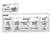
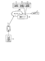
- FIG. 1 is an explanatory diagram illustrating a system configuration according to the first embodiment.
- FIG. 2 is a block diagram illustrating configurations of the terminal device and the authentication server according to the first embodiment.
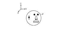
- FIG. 3 is an explanatory diagram for explaining the orientation of the face.
- FIG. 4 is an explanatory diagram for explaining the inclination of the face.
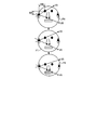
- FIG. 5 is an explanatory diagram for explaining an inter-feature vector / feature angle in the right / left inclination of the face.
- FIG. 6 is an explanatory diagram for explaining an inter-feature vector / feature angle in a vertical tilt of a face.
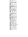
- FIG. 7 is an explanatory diagram for explaining ID management.
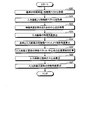
- FIG. 8 is a flowchart illustrating an example of an operation related to face authentication.
- FIG. 8 is a flowchart illustrating an example of an operation related to face authentication.
- FIG. 10A is an explanatory diagram illustrating the positional relationship of feature points in a face facing front.
- FIG. 10B is an explanatory diagram illustrating the positional relationship of feature points in a face facing left.
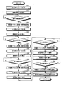
- FIG. 11 is a flowchart illustrating an example of reference face information registration processing.
- FIG. 12 is an explanatory diagram illustrating a display example of a message image.
- FIG. 13 is an explanatory diagram illustrating a system configuration according to the second embodiment.
- FIG. 14 is a block diagram illustrating configurations of a terminal device and an authentication server according to the second embodiment.
- FIG. 15 is an explanatory diagram illustrating an example of a computer that executes a face authentication program.
- a face authentication device a face authentication method, and a face authentication program according to embodiments will be described with reference to the drawings.
- configurations having the same functions are denoted by the same reference numerals, and redundant description is omitted.
- the face authentication device, the face authentication method, and the face authentication program described in the following embodiments are merely examples, and do not limit the embodiments.
- the following embodiments may be appropriately combined within a consistent range.
- FIG. 1 is an explanatory diagram illustrating a system configuration according to the first embodiment.
- the terminal device 1 is a device such as a personal computer or a tablet-type mobile terminal, and is connected to an external device such as an authentication server 2 or a Web server 3 via a communication network NW such as the Internet. To do.
- the terminal device 1 stores face information U1, U2, U3 for face authentication for each user (user).
- the terminal device 1 performs face authentication by collating the face of the input image G1 obtained by a digital camera provided, for example, at the top of the display screen and the face information U1, U2, U3 stored in advance, and is authenticated. Allow users to use it. As a result, the terminal device 1 can be prevented from being used as a regular user by a user for whom the face information U1, U2, U3 is not set, and security is improved.
- the authentication server 2 performs logon authentication to various services provided by the Web server 3 or the like in response to a request from the terminal device 1 by an operation of a user authenticated by face authentication.
- the Web server 3 provides a Web service that allows a predetermined Web page to be browsed to the terminal device 1 that has been authenticated by the authentication server 2.
- the Web server 3 may be a server device that provides an SNS (social network service), a video chat service, a service for transmitting images and videos to a partner terminal via the communication network NW, and the like.
- FIG. 2 is a block diagram showing configurations of the terminal device 1 and the authentication server 2 according to the first embodiment.
- the terminal device 1 includes a video processing unit 10, an authentication processing unit 20, and a communication unit 30.
- the video processing unit 10 is a processing unit that performs image processing on various videos, and performs image processing on an input image G1 obtained by imaging with a digital camera provided in the terminal device 1, for example.
- the video processing unit 10 includes an image input unit 11 and an image range detection unit 12.
- the image input unit 11 receives an input of an input image G1 captured by a digital camera provided in the terminal device 1.
- the image range detection unit 12 recognizes a face included in the input image G1 received by the image input unit 11, and detects an image range of the recognized face.
- the image range detection unit 12 outputs the image data of the face image range detected from the input image G ⁇ b> 1 to the authentication processing unit 20. Note that recognition of a face included in the input image G1 is performed using a known technique such as recognition of a skin color region of a face shape by combining shape recognition by color extraction, color recognition, and the like.
- FIG. 3 is an explanatory diagram for explaining the orientation of the face F.
- the orientation of the face F included in the input image G1 is not always directed to the front, but may be inclined around the X, Y, and Z axes. Specifically, as shown in the illustrated example, the face F may turn left about the Y axis.
- FIG. 4 is an explanatory diagram for explaining the inclination of the face.
- the digital camera for face authentication includes a face F1 facing front, faces F2 and F3 tilted left and right, and faces F4 and F5 tilted up and down.
- the image data of the face F1 is detected from the input image G1 from the digital camera and output to the authentication processing unit 20.
- the face orientation may not be the front orientation but may be inclined like the faces F2 to F5.
- the image data of the tilted face orientation faces F2 to F5 is output to the authentication processing unit 20.
- the authentication processing unit 20 is a processing unit that performs face authentication by comparing the face included in the input image G1 with face information stored in advance.
- the authentication processing unit 20 includes a feature point extraction unit 21, an inter-feature vector detection unit 22, a feature angle calculation unit 23, a position calculation unit 24, a personal feature DB 25, and a display processing unit 26.
- the feature point extraction unit 21 receives the face image data detected from the input image G1 from the image range detection unit 12, and identifies and extracts a plurality of feature points set in advance as characteristic parts of the face F.
- This feature point may be any part as long as it is a characteristic part in the face F.
- eyes for example, pupils
- ears for example, ear holes
- nose for example, nostrils
- mouth for example
- Kuroko Kuroko
- the feature point extraction unit 21 identifies a plurality of feature points in the image of the face F by analyzing the image data of the face F detected from the input image G1 using a known technique that combines shape recognition, color recognition, and the like. And extract. For each of a plurality of extracted feature points, the feature point extracting unit 21 uses information for identifying the feature points (for example, a flag indicating the right eye, left eye, etc.) and a position in the image (for example, the coordinates of the pixel) as an inter-feature vector. Output to the detector 22.
- the inter-feature vector detection unit 22 is based on the plurality of feature points detected by the feature point extraction unit 21, and is paired with two feature points (first and second feature points). And a feature-to-feature vector based on a feature point (third feature point) deviating from a straight line connecting the two feature points.
- the first and second feature points to be paired are any combination of two feature points, such as both eyes and both ears, left eye and left nostril, right eye and right nostril. May be.
- the third feature point may be any one that deviates from a straight line connecting the first and second feature points, for example, a nostril for both eyes.
- the combinations of the first to third feature points are set in advance, and the inter-feature vector detection unit 22 generates information for identifying the feature points from the plurality of feature points detected by the feature point extraction unit 21. First to third corresponding feature points are obtained. Then, the inter-feature vector detection unit 22 detects two inter-feature vectors connecting the first and second feature points from the third feature point.
- the feature angle calculation unit 23 calculates a feature angle based on the two feature vectors detected by the feature vector detection unit 22. This feature angle is an angle formed by two inter-feature vectors connecting the first and second feature points with the third feature point as the center.
- FIG. 5 is an explanatory diagram for explaining the feature-to-feature vector / feature angle in the left-right inclination of the face.
- the inter-feature vectors V1 and V2 are vectors passing through both eyes (first and second feature points) with the left nostril being the center (third feature point).
- the inter-feature vectors V3 and V4 are vectors passing through both eyes (first and second feature points) centered on the right nostril (third feature point).
- the distance W1 is the height from the nostril to the eye, and the distance W2 is the width of both eyes.
- the positional relationship between the eyes and the nostrils is determined by a digital camera.
- the input image G1 photographed two-dimensionally, that is, the appearance, differs depending on the face direction.
- the apparent feature angle formed by the feature vectors V1 and V2 centering on the left nostril is narrower in the face F2 facing right than the face F1 in front.
- the distance W1 changes (becomes narrower) in the right-facing face F2 with respect to the front face F1, but the distance W2 does not change.
- FIG. 6 is an explanatory diagram for explaining the feature-to-feature vector and feature angle when the face is tilted up and down.
- the inter-feature vectors V5 and V6 center around the hole in the right ear (third feature point) and pass through the right eye and the right hole (first and second feature points) in the nose. It is.
- the distance W3 is the height from the right ear hole to the right eye
- the distance W4 is the width from the right ear hole to the right eye.
- the first to third feature points may be any combination as long as they do not line up with a straight line.
- the positional relationship between the hole in the right ear and the right hole in the right eye and nose is
- the input image G1 photographed two-dimensionally with a digital camera, that is, the appearance, differs depending on the face orientation.
- the apparent feature angle formed by the inter-feature vectors V5 and V6 about the right ear hole is narrower in the downward face F5 than in the front face F1.
- the distance W3 changes in the downward face F5 with respect to the front face F1, but the distance W4 does not change.
- the positional relationship of the feature points on the face F is different for each individual, it can be used as information for identifying the individual.
- the positional relationship between the apparent feature points varies depending on the face orientation. Therefore, the third feature point (for example, one of both nostrils) is defined as the center from the face F of the input image G1, and the inter-feature vector from the center to the first and second feature points (for example, both eyes) is defined.
- An individual can be identified by calculating in consideration of the face orientation.
- the position calculation unit 24 uses a feature between two features for authenticating the person. Data related to the positional relationship of vectors is calculated.
- the authentication processing unit 20 collates the data related to the positional relationship calculated by the position calculating unit 24 with the data related to the positional relationship between the two feature vectors based on the feature angles included in the face information stored in advance, and the same. Face recognition is performed by checking the sex. The details of the process for calculating the data relating to the positional relationship between the two feature vectors and performing face authentication will be described later.
- the personal feature DB 25 is a database (DB) that stores information on feature points of the user's face for each user. Specifically, the personal feature DB 25 has a feature point in each face direction (front, right, left, upward, downward) for each ID (for example, user No., user ID, etc.) for identifying the user.
- the inter-feature vector and feature angle information are stored.
- the display processing unit 26 is a processing unit that causes a display or the like to display a message or the like related to face authentication or a message or the like related to the setting of face information serving as a reference for face authentication. Details of display on the display by the display processing unit 26 will be described later.
- the communication unit 30 communicates with the authentication server 2 and the Web server 3 via the communication network NW.
- the communication unit 30 includes a service connection unit 31 and an ID management unit 32.
- the service connection unit 31 performs processing for connecting to a Web service provided by the Web server 3 based on the face authentication of the authentication processing unit 20. Specifically, when the user himself / herself can be confirmed by the face authentication of the authentication processing unit 20, the service connection unit 31 gives permission information including a user ID for identifying the confirmed user to the ID management unit 32. Is notified to the authentication server 2. Thus, the authentication server 2 permits the user who has been authenticated by face authentication to connect to the web service provided by the web server 3. After receiving a response indicating permission from the authentication server 2, the service connection unit 31 connects to the Web service provided by the Web server 3.
- the ID management unit 32 manages information (management data) for each user. Specifically, for each user, the ID management unit 32 manages, as management data, the user ID and face information of each face of the user (front, right, left, upward, and downward).
- the personal feature DB 25 reflects the management data information of the ID management unit 32.
- FIG. 7 is an explanatory diagram for explaining ID management.
- the ID management unit 32 as management data D1, for each user, “user No.”, “user ID” for identifying the user, and “Pass Word” set by the user. , It manages the reference face information for each face orientation of the user.
- the face information for each face orientation of the user is front data, left side data, right side data, top side data, bottom side data, etc., and includes information on feature vectors and feature angles for each of the front, left side, right side, top side, and bottom side. It is.
- the inter-feature vector and feature angle that are centered on the left hole of the nose and the inter-feature vector that is centered on the right hole of the nose and the center of the eye. And feature angles etc. are included.
- the authentication server 2 has a management DB 40 and a connection information management unit 50.
- the management DB 40 manages user IDs included in the permission information notified from the terminal device 1.
- the connection information management unit 50 starts communication connection of the terminal device 1 to the Web service provided by the Web server 3 based on the permission information notified from the terminal device 1, and connection information about the started communication connection Manage. Thereby, the terminal device 1 can enjoy the Web service provided by the Web server 3.
- FIG. 8 is a flowchart illustrating an example of an operation related to face authentication. This flowchart is started, for example, when an authentication application is activated when starting a Web service, an SNS service, or the like, or when confirming the identity while continuing the started service. .
- the authentication processing unit 20 performs authentication by referring to the personal feature DB 25 based on the user ID input from the operation unit 110a (see FIG. 15) or the like.
- the face information set in advance for the person who performs the process is acquired (S1).
- the acquisition of the face information may be performed only once when a service such as a Web service is started, and may be stored in a RAM (Random Access Memory) of the terminal device 1 or the like. Therefore, if the user is to be confirmed while the service is being continued, the face image stored in the RAM may be acquired.
- the video processing unit 10 receives an input of the input image G1 captured by the digital camera provided in the terminal device 1 by the image input unit 11 (S2). Next, the video processing unit 10 performs image detection on the received input image G1 by the image range detection unit 12 (S3), and determines whether the image range detection unit 12 has detected the face image range. (S4).
- the video processing unit 10 determines whether or not the process times out because a predetermined time has elapsed since the process was started (S5). When the timeout does not occur (S5: NO), the video processing unit 10 returns to S3 and continues the processing. When the time-out occurs (S5: YES), the video processing unit 10 advances the process to S6. In S6, the display processing unit 26 displays on the display or the like that the service cannot be used because the face image range cannot be detected and face authentication cannot be performed.
- the authentication processing unit 20 extracts the feature points from the input image G1 by the feature point extraction unit 21, and then inputs the feature points from the feature vector detection unit 22.
- An inter-feature vector of the image G1 is acquired (S7).
- the authentication processing unit 20 acquires a feature angle / inter-feature vector of the face information from the face information acquired in S1 (S8).
- the authentication processing unit 20 calculates the feature angle of the input image G1 by the feature angle calculation unit 23 (S9).
- the authentication processing unit 20 uses the position calculation unit 24 to calculate data regarding the positional relationship between the feature angle / inter-feature vector of the input image G1 and the feature angle / inter-feature vector of the face information, and compares the calculated data. (S10).
- the authentication processing unit 20 determines whether or not the face is the person's face preset in the personal feature DB 25 by comparison in S10 (S11). Specifically, the authentication processing unit 20 identifies the identity between the positional relationship between the feature angle / inter-feature vector of the input image G1 and the positional relationship between the feature angle / inter-feature vector of the face information, that is, the degree of similarity of the mutual positional relationship. Is determined to be the person's face based on whether or not is within a predetermined range.
- the authentication processing unit 20 If it is the person's face (S11: YES), the authentication processing unit 20 notifies the communication unit 30 that the person has been verified by face authentication. As a result, the communication unit 30 connects to the Web service provided by the Web server 3 (S12). If it is not the person's face (S11: NO), the authentication processing unit 20 causes the display processing unit 26 to display on the display or the like that the service cannot be used because the identity cannot be confirmed by face authentication (S6).
- FIG. 9 is a flowchart showing the calculation process.
- the position calculation unit 24 acquires a preset feature angle / inter-feature vector of the user as a reference based on the data acquired in S8 (S20). ).
- the case where the face direction of the reference person is the front direction is illustrated.
- the position calculation unit 24 acquires an inter-feature vector from the input image G1 based on the data acquired in S7 (S21). Next, the position calculation unit 24 selects the center point for obtaining the feature angle, that is, the center point (third feature point) when the inter-feature vector detection unit 22 detects the inter-feature vector, as the inter-feature vector detection unit 22. (S22).
- the feature angle calculation unit 23 calculates the feature angle of the input image G1 based on the preset feature angle / inter-feature vector of the reference person and the inter-feature vector acquired from the input image G1. (S23). Next, the feature angle calculation unit 23 is included in the input image G1 with respect to the reference face direction (front direction) based on the preset inter-feature vector of the reference person and the inter-feature vector of the input image G1. An inclination angle indicating the inclination of the face to be detected is calculated (S24).
- the position calculation unit 24 calculates the positional relationship between the feature vectors and the center point when the face orientation included in the input image G1 is front (S25), and the face orientation included in the input image G1 is the orientation of the face.
- the center point and feature angle at the time of front are calculated (S26, S27).
- FIG. 10A is an explanatory diagram illustrating the positional relationship between feature points (K, L, M) in a face facing front.
- FIG. 10B is an explanatory diagram illustrating the positional relationship between feature points (G, H, J) in a face facing left.
- FIG. 10A and 10B are diagrams in which the feature points of the face F are projected from the Y direction to the ZX plane in FIG. 3, and the center of rotation when the face F is tilted from the front to the left is defined as O. .
- Q in FIG. 10A is an intersection of a line obtained by extending KL in the X-axis direction and a line obtained by extending M in the Z-axis direction.
- U, V, and W are points on the X-axis of K, L, and M
- the feature points K, L, and M are pixel positions in the X-axis direction when the digital camera is used to shoot the feature points. Equivalent to.
- R, S, and T in FIG. 10B are points on the X axis of G, H, and J, and the feature points G, H, and J are pixel positions in the X axis direction when the digital camera is photographed from the front. Equivalent to.
- FIG. 10A is assumed to be a front-facing face feature point as a reference
- FIG. 10B is an example of a left-facing face feature point included in the input image G1.
- the feature points (K, L, M) in the face facing forward in FIG. 10A and the feature points (G, H, J) in the face facing left in FIG. 10B indicate the same feature points.
- FIG. 10A shows both eyes (K, L) in a front-facing face and a right ear hole (M) in a front-facing face.
- FIG. 10B shows both eyes (G, H) in a left-facing face and a right ear hole (J) in a left-facing face.
- the magnitude relationship of RS ⁇ UV, ST> VW is established between the distance RS and the distance UV, which are apparent distances, and the distance ST and the distance VW.
- Each distance in this magnitude relationship changes with the inclination of the face, but the magnitude relationship does not change.
- ⁇ GHN which is the tilt angle of the left face with respect to the front
- ⁇ ⁇ GHN ACOS (NH / GH)
- arcos inverse cosine function
- ⁇ JHP ACOS (JP / HJ).
- KL KL
- RS a detected value detected from the input image G1.
- the person can be authenticated. That is, if the detected value detected from the input image G1 is substituted into the relationship of the stored value set (saved) as the reference face information, the user may be authenticated.
- ⁇ MLQ ⁇ GHN + ⁇ JHP is valid as long as you are the principal.
- the LM is data that is calculated from the front-facing and left-facing images of the reference person's face and stored in the personal feature DB 25. That is, the LM is calculated for the person based on the images obtained from the front and left sides, and stored in the personal feature DB 25 as data for obtaining the feature angle.
- the codes corresponding to G, H, J, R, S, and T in FIG. 10B are denoted by G ′, H ′, J ′, R ′, S ′, T Then, the following formula is established.
- ACOS (LM (Eigenvalue) / VW (Saved Value)) ACOS (R ′S ′ (Detected Value) / GH (Saved Value)) + ACOS (S′T ′ (Detected Value) / H′J ′ (Eigenvalue))
- LM H'J 'holds because the image is the person's own image. Therefore, LM that is an eigenvalue can be calculated by the following equation.
- ACOS (LM / VW) ACOS (R ′S ′ / GH) + ACOS (S′T ′ / LM) (Equation 2 in feature angle)
- ⁇ MLQ is stored in the personal feature DB 25 as a feature angle that identifies the principal.
- the terminal device 1 extracts a plurality of feature points of a face included in the input image G1, and the first and second feature points that are paired among the plurality of feature points, and the first and first feature points.
- a third feature point deviating from a straight line connecting the two feature points and two inter-feature vectors from the third feature point to the first and second feature points are detected.
- the terminal device 1 calculates a feature angle based on the detected two feature vectors, and a feature angle based on the two feature vectors included in the face information preset in the personal feature DB 25 as a face to be authenticated. And face authentication based on the calculated feature angle. Thereby, in the terminal device 1, even if the face included in the input image G1 is inclined, face authentication can be performed.
- the face information preset in the personal feature DB 25 includes two feature vectors when a face in a predetermined direction is photographed and feature angles based on the two feature vectors. .
- the feature angle calculation unit 23 the orientation of the face included in the input image G1 with respect to the orientation of the face in the face information based on the two inter-feature vectors included in the face information and the detected two inter-feature vectors.
- An inclination angle indicating the inclination of is calculated.
- the authentication processing unit 20 detects two features based on the calculated feature angle when the face direction included in the input image G1 is the face direction in the face information.
- Face authentication is performed based on whether or not the positional relationship of the interval vectors matches the positional relationship of the face information. For example, face authentication is performed based on whether or not the stored value and the measured value are included in the positional relationship between the two feature vectors (equation 1 in the feature angle) and within the allowable error range. Thereby, even if the face included in the input image G1 is inclined with respect to the reference face that is front-facing, face authentication can be easily performed.
- the rotation angle with respect to the reference arrangement position of the face is extracted as a pixel pattern, and each pixel extraction pattern corresponds to the image feature amount
- a technique for determining the rotation angle and the face direction by doing so.
- the method of identifying individuals by the distance between the eyes due to changes in luminance values, the distance between feature points that extract the mouth and the size of the mouth in the horizontal direction, the aspect ratio of the eyes, There is also known a method of detecting a target person by extracting a position relationship, the level of eyes, and the like as criteria.
- the above-described technique cannot obtain an accurate numerical value unless a person is positioned in front of the camera for extracting the coordinates of a fixed feature point or extracting the distance between feature points. Also, for example, even when determining the level of eyes, etc., it is only necessary to grasp the situation that the face is tilted, and to determine that it is the same as the original image for authentication stored in the device. I can't.
- the straight line connecting the eyes can correct the face facing up and down, but if it faces in the horizontal direction, the slope of the straight line does not matter whether the face is front or sideways. There is no difference and it cannot be used for authentication when the face is tilted horizontally.
- Patent Document 1 it is determined whether or not the color region is a front face image of a person by searching a portion corresponding to the eye from a light and dark pattern.
- a method is disclosed in which a position corresponding to each organ in the front face image is detected from the number of appearances of the skin color, a distance between each organ is calculated, and an individual is identified from the relationship of the distance. This method can only determine whether or not a person is a front image.
- the tilt correction method disclosed in Patent Document 1 is merely an image coordinate transformation used when creating a 3D graphic image in which an image of an area having a plurality of predetermined color information and an input image are mapped by affine transformation. For this reason, it is only possible to determine whether or not the image is tilted (detection of tilt) based on the color information from the light / dark pattern of the face. Therefore, it is not a method for determining whether or not the tilted face included in the input image is the person himself / herself. Further, the method for calculating the distance between each organ is only a normal image authentication method. Even if the face is tilted up and down, not up and down, the tilted image is not corrected, and it cannot be determined that the person is tilted.
- Patent Document 2 discloses a method of extracting a feature pattern from a local region, generating a plurality of pins constituting the feature pattern, and performing image recognition thereby.
- this method it is possible to recognize the line of sight of the face by connecting many pins that make up the face, but many pins that can make up the face must be detected as feature points.
- the overall configuration for recognizing is based on the face contour edge and the gradient direction. For this reason, the process for creating pins is enormous, and the real-time authentication in the SNS service is too burdensome.
- the face authentication of the terminal device 1 even if the face included in the input image G1 is tilted, face authentication can be easily performed.
- the load in real-time authentication during service can also be reduced.
- the setting (registration) of face information as a standard for face authentication is one of the processes performed by the authentication processing unit 20 based on a setting operation input from the operation unit 110a (see FIG. 15) or the like.
- FIG. 11 is a flowchart illustrating an example of reference face information registration processing.
- the authentication processing unit 20 receives the user ID of the user who sets the front data, left side data, right side data, top side data, bottom side data, etc. in the management data D1 and the personal feature DB 25, and starts the registration process.
- the authentication processing unit 20 displays a front message for guiding the digital camera of the terminal device 1 to face the front by the display processing unit 26. It is displayed on the play (S30).
- FIG. 12 is an explanatory diagram illustrating a display example of the message G12.
- the display processing unit 26 displays an input image G11, a message G12, and an operation button G13 on the display screen G10.
- the input image G11 is an image obtained by being captured by the digital camera of the terminal device 1.
- the user can confirm the face orientation included in the input image G11 by confirming the input image G11.
- the message G12 has a content for guiding the digital camera of the terminal device 1 so that the face is directed to the front. As a result, the user can take a picture with the face facing the front of the digital camera of the terminal device 1.
- the operation button G13 is a button for instructing to capture a face. The user can instruct photographing of the face by operating the operation button G13.
- the message G12 may be superimposed on the input image G11.
- the position of the eyes, nose, mouth, etc. when facing the front may be drawn as a message G12 on the input image G11 for guidance.
- the message G12 superimposed on the input image G11 it is possible to guide in a more accurate face direction.
- the authentication processing unit 20 receives an image by the image input unit 11 and detects a face by the image range detection unit 12 (S31), and determines whether or not an image in front of the face has been extracted (S32).
- S32 in the input image G11 captured by operating the operation button G13 when the message G12 is displayed, the face front image cannot be extracted when the image range detection unit 12 cannot detect the face. It determines with (S32: NO) and waits for a process.
- the authentication processing unit 20 assumes that the front face image has been extracted, and obtains the feature vector by the feature vector detection unit 22 and the feature by the feature angle calculation unit 23. An angle is calculated (S33).
- the authentication processing unit 20 causes the display processing unit 26 to display a message for the upper surface that guides the digital camera of the terminal device 1 to face upwards (S34).
- the authentication processing unit 20 receives an image by the image input unit 11 and detects a face by the image range detection unit 12 (S35), and determines whether an image of the upper face of the face has been extracted (S36).
- S36 when the image range detection unit 12 cannot detect the face in the input image G1 captured by operating the operation button G13 while displaying the message G12 for the upper surface, the image of the upper surface of the face can be extracted. It is determined that there was not (S36: NO), and the process is waited for.
- the authentication processing unit 20 assumes that the image of the upper surface of the face has been extracted, obtains the feature vector by the feature vector detection unit 22, and features by the feature angle calculation unit 23. An angle is calculated (S37).
- the authentication processing unit 20 causes the display processing unit 26 to display a message for the lower surface that guides the digital camera of the terminal device 1 to face downward with the display processing unit 26 (S38).
- the authentication processing unit 20 receives an image by the image input unit 11 and detects a face by the image range detection unit 12 (S39), and determines whether an image of the lower surface of the face has been extracted (S40).
- S40 an image of the lower surface of the face can be extracted when the image range detection unit 12 cannot detect the face in the input image G11 captured by operating the operation button G13 while the message G12 for the lower surface is displayed. It is determined that there was not (S40: NO), and the process is waited for.
- the authentication processing unit 20 assumes that the image of the lower surface of the face has been extracted, obtains the feature vector by the feature vector detection unit 22, and features by the feature angle calculation unit 23. An angle is calculated (S41).
- the authentication processing unit 20 causes the display processing unit 26 to display a message for the right side for guiding the digital camera of the terminal device 1 to face rightward on the display (S42).
- the authentication processing unit 20 receives an image by the image input unit 11 and detects a face by the image range detection unit 12 (S43), and determines whether an image of the right face of the face has been extracted (S44).
- S44 an image of the right face of the face can be extracted from the input image G11 captured by operating the operation button G13 when the right face message G12 is displayed, if the face cannot be detected by the image range detection unit 12. It is determined that there is not (S44: NO), and the process is waited for.
- the authentication processing unit 20 assumes that the image of the right face of the face has been extracted, obtains the feature vector by the feature vector detection unit 22, and features by the feature angle calculation unit 23. An angle is calculated (S45).
- the authentication processing unit 20 causes the display processing unit 26 to display a message for the left side for guiding the digital camera of the terminal device 1 to face leftward on the display (S46).
- the authentication processing unit 20 receives an image by the image input unit 11 and detects a face by the image range detection unit 12 (S47), and determines whether an image of the left face of the face has been extracted (S48).
- S48 in the input image G11 captured by operating the operation button G13 while the left message G12 is displayed, the image of the left face of the face can be extracted when the image range detection unit 12 cannot detect the face. It is determined that there was not (S48: NO), and the process is waited for.
- the authentication processing unit 20 assumes that the image of the left face of the face has been extracted, obtains the feature vector by the feature vector detection unit 22, and features by the feature angle calculation unit 23. An angle is calculated (S49). Next, the authentication processing unit 20 registers (updates) the feature vectors and feature angles calculated in S33, S37, S41, S45, and S49 in the management data D1 and the personal feature DB 25 as reference face information (S50). . Thereby, in the terminal device 1, the management data D1 and the front data, the left surface data, the right surface data, the upper surface data, the lower surface data, and the like in the personal feature DB 25 can be set.
- FIG. 13 is an explanatory diagram illustrating a system configuration according to the second embodiment. As shown in FIG. 13, the second embodiment is different from the first embodiment in that an input image G1 is transmitted from the terminal device 1a to the authentication server 2a, and face authentication is performed by the authentication server 2a.
- FIG. 14 is a block diagram showing the configuration of the terminal device 1a and the authentication server 2a according to the second embodiment. As shown in FIG. 14, the point from which the authentication process part 20 is provided in the authentication server 2a differs from 1st Embodiment (refer FIG. 2).
- the terminal device 1a transmits an input image G1 obtained by photographing with a digital camera to the authentication server 2a together with the user ID.
- the authentication processing unit 20 of the authentication server 2a reads user face information from the personal feature DB 25 based on the user ID transmitted from the terminal device 1a.
- the authentication process part 20 of the authentication server 2a performs the process of face authentication collated with the read face information based on the input image G1 transmitted from the terminal device 1a.
- the connection information management unit 50 permits the web service to the terminal device 1a by the web server 3, and connects the web server 3 and the terminal device 1a by the permitted web service. Manage as connection information. Thereby, a Web service is provided from the Web server 3 to the terminal device 1a.
- FIG. 15 is a diagram for explaining an example of a computer that executes the face authentication program according to the first and second embodiments.
- the computer 100 includes an operation unit 110 a, a speaker 110 b, a camera 110 c, a display 120, and a communication unit 130.
- the computer 100 further includes a CPU 150 (CPU: Central Processing Unit), a ROM 160 (ROM: Read Only Memory), an HDD 170 (HDD: Hard Disk Drive), and a RAM 180. These units 110 to 180 are connected via a bus 140.
- the HDD 170 stores in advance a face authentication program 170 a that exhibits the same functions as the video processing unit 10, the authentication processing unit 20, and the communication unit 30 described in the first and second embodiments.
- the face authentication program 170a may be integrated or separated as appropriate, as with each component of each functional unit shown in FIG. In other words, all data stored in the HDD 170 need not always be stored in the HDD 170, and only data necessary for processing may be stored in the HDD 170.
- the CPU 150 reads the face authentication program 170a from the HDD 170 and develops it in the RAM 180.
- the face authentication program 170a functions as a face authentication process 180a.
- the face authentication process 180a develops various data read from the HDD 170 in an area allocated on the RAM 180 as appropriate, and executes various processes based on the developed data.
- the face authentication process 180a includes processing executed by the video processing unit 10, the authentication processing unit 20, and the communication unit 30 illustrated in FIG.
- each processing unit virtually realized on the CPU 150 does not always require that all the processing units operate on the CPU 150, and only a processing unit necessary for processing needs to be virtually realized.
- the face authentication program 170a is not necessarily stored in the HDD 170 or the ROM 160 from the beginning.
- each program is stored in a “portable physical medium” such as a flexible disk inserted into the computer 100, so-called FD, CD-ROM, DVD disk, magneto-optical disk, or IC card.
- the computer 100 may acquire and execute each program from these portable physical media.
- Each program is stored in another computer or server device connected to the computer 100 via a public line, the Internet, a LAN, a WAN, etc., and the computer 100 acquires and executes each program from these. It may be.
Abstract
A face authentication device (1) according to an embodiment comprises an extraction unit (21), a detection unit (22), a feature angle computation unit (23), and an authentication unit (20). The extraction unit (21) extracts a plurality of feature points of a face included in an inputted image. The detection unit (22) detects first and second feature points which are a pair among the plurality of feature points, a third feature point which is removed from a line which joins the first and second feature points, and two feature vectors from the third feature point to the first and second feature points. The feature angle computation unit (23) computes a feature angle from the detected two feature vectors. The authentication unit (20) carries out face authentication on the basis of the feature angle from the two feature vectors included in facial information which is preset as a face to be authenticated and the computed feature angle.
Description
本発明の実施形態は、顔認証装置、顔認証方法および顔認証プログラムに関する。
Embodiments described herein relate generally to a face authentication device, a face authentication method, and a face authentication program.
従来、パーソナルコンピュータ、タブレット型携帯端末等の端末装置あるいは接続されるサーバには、カメラによる入力画像より顔情報を認識し、端末装置あるいはサーバに予め保存されている本人の顔情報と照合して本人の認証(以下、顔認証とよぶ)を行うものがある。端末装置あるいはサーバでは、この顔認証によって本人と認識することにより、端末装置のログイン認証やサーバを利用したWeb等のサービスの利用許可を行っている。
Conventionally, a terminal device such as a personal computer or a tablet-type portable terminal or a connected server recognizes face information from an input image from a camera and compares it with the face information of the person stored in advance in the terminal device or server. Some perform authentication of the person (hereinafter referred to as face authentication). The terminal device or the server recognizes the person himself / herself through the face authentication, thereby permitting the login authentication of the terminal device or the use of a service such as Web using the server.
この顔認証では、入力画像の顔にある目、鼻、口、黒子(ほくろ)等の特徴的な部位(以下、特徴点とよぶ)を特定し、その特徴点による部位の位置や特徴点同士の距離(以下、特徴点間距離とよぶ)や、顔に対する各部位の位置や大きさ、色等を判別し、予め保存されている本人の顔情報と照合する。
In this face authentication, characteristic parts (hereinafter referred to as feature points) such as eyes, nose, mouth, and moles (hereinafter referred to as feature points) in the face of the input image are specified, and the positions of the parts and the feature points between the feature points are identified. Distance (hereinafter referred to as distance between feature points), the position, size, color, and the like of each part with respect to the face, and collated with the face information stored in advance.
ところで、カメラの前では、正面向きの顔が常にあるとは限らず、横向きや上向きの顔である場合もある。したがって、入力画像における顔の向きは、常に同じ向きであるとは限らない。このため、ログイン認証後に使用する人や、利用許可後のサービスの利用者を顔認証によって定期的にチェックする場合には、正面向きだけでなく上下、左右に傾いた顔による顔認証を行う必要がある。
By the way, in front of the camera, there is not always a face facing forward, but there may be a face facing sideways or upward. Therefore, the orientation of the face in the input image is not always the same. For this reason, when periodically checking the person who uses after login authentication and the user of the service after use permission by face authentication, it is necessary to perform face authentication not only with the front facing but also with a face tilted up and down, left and right There is.
しかしながら、上述した従来技術では、予め保存されている本人の顔情報における顔の向きと、入力画像の顔の向きとが異なる場合には、特徴点の位置、特徴点間距離が顔の向きによって大きく変化することから、本人と認識することができない場合があった。例えば、予め保存されている本人の顔情報における顔の向きが正面向きである場合、上下、左右に傾いた顔による顔認証を正確に行うことができなかった。
However, in the above-described prior art, when the face direction in the face information of the person stored in advance is different from the face direction of the input image, the position of the feature point and the distance between the feature points depend on the face direction. Because it changed greatly, there were cases where it was not possible to recognize the person. For example, when the face orientation in the person's face information stored in advance is the front orientation, face authentication using a face tilted up and down and left and right cannot be performed accurately.
一つの側面では、顔が傾いていても顔認証できることにある。
In one aspect, face recognition can be performed even if the face is tilted.
一つの態様では、顔認証装置は、抽出部と、検出部と、特徴角度算出部と、認証部とを備える。抽出部は、入力画像に含まれる顔の複数の特徴点を抽出する。検出部は、複数の特徴点の中で対となる第1および第2の特徴点と、当該第1および第2の特徴点を結ぶ直線から外れた第3の特徴点と、第3の特徴点から第1および第2の特徴点までの2つの特徴間ベクトルとを検出する。特徴角度算出部は、検出された2つの特徴間ベクトルによる特徴角度を算出する。認証部は、認証対象とする顔として予め設定された顔情報に含まれる、2つの特徴間ベクトルによる特徴角度と、算出された特徴角度とに基づいて顔認証を行う。
In one aspect, the face authentication device includes an extraction unit, a detection unit, a feature angle calculation unit, and an authentication unit. The extraction unit extracts a plurality of feature points of the face included in the input image. The detection unit includes a first feature point and a second feature point that are paired among a plurality of feature points, a third feature point that deviates from a straight line connecting the first and second feature points, and a third feature point. Two inter-feature vectors from the point to the first and second feature points are detected. The feature angle calculation unit calculates a feature angle based on the detected two feature vectors. The authentication unit performs face authentication based on a feature angle based on two feature vectors included in face information preset as a face to be authenticated and the calculated feature angle.
一つの側面として、顔が傾いていても顔認証できる。
As one aspect, face recognition can be performed even if the face is tilted.
以下、図面を参照して、実施形態にかかる顔認証装置、顔認証方法および顔認証プログラムを説明する。実施形態において同一の機能を有する構成には同一の符号を付し、重複する説明は省略する。なお、以下の実施形態で説明する顔認証装置、顔認証方法および顔認証プログラムは、一例を示すに過ぎず、実施形態を限定するものではない。また、以下の各実施形態は、矛盾しない範囲内で適宜組みあわせてもよい。
Hereinafter, a face authentication device, a face authentication method, and a face authentication program according to embodiments will be described with reference to the drawings. In the embodiment, configurations having the same functions are denoted by the same reference numerals, and redundant description is omitted. Note that the face authentication device, the face authentication method, and the face authentication program described in the following embodiments are merely examples, and do not limit the embodiments. In addition, the following embodiments may be appropriately combined within a consistent range.
(第1の実施形態)
図1は、第1の実施形態にかかるシステム構成を説明する説明図である。図1に示すように、端末装置1は、パーソナルコンピュータ、タブレット型携帯端末等の機器であり、インターネットなどの通信ネットワークNWを介して認証サーバ2、Webサーバ3などの外部機器と通信可能に接続する。 (First embodiment)
FIG. 1 is an explanatory diagram illustrating a system configuration according to the first embodiment. As shown in FIG. 1, theterminal device 1 is a device such as a personal computer or a tablet-type mobile terminal, and is connected to an external device such as an authentication server 2 or a Web server 3 via a communication network NW such as the Internet. To do.
図1は、第1の実施形態にかかるシステム構成を説明する説明図である。図1に示すように、端末装置1は、パーソナルコンピュータ、タブレット型携帯端末等の機器であり、インターネットなどの通信ネットワークNWを介して認証サーバ2、Webサーバ3などの外部機器と通信可能に接続する。 (First embodiment)
FIG. 1 is an explanatory diagram illustrating a system configuration according to the first embodiment. As shown in FIG. 1, the
端末装置1は、利用者(ユーザ)ごとに顔認証のための顔情報U1、U2、U3を記憶している。端末装置1は、例えば表示画面の上部などに設けられたデジタルカメラにより得られる入力画像G1の顔と、予め記憶された顔情報U1、U2、U3とを照合して顔認証を行い、認証された利用者に対して使用を許可する。これにより、端末装置1は、正規の利用者として顔情報U1、U2、U3が設定されていない利用者には使用させないようにすることができ、セキュリティを高めている。
The terminal device 1 stores face information U1, U2, U3 for face authentication for each user (user). The terminal device 1 performs face authentication by collating the face of the input image G1 obtained by a digital camera provided, for example, at the top of the display screen and the face information U1, U2, U3 stored in advance, and is authenticated. Allow users to use it. As a result, the terminal device 1 can be prevented from being used as a regular user by a user for whom the face information U1, U2, U3 is not set, and security is improved.
認証サーバ2は、顔認証により認証された利用者の操作による端末装置1からの要求に応じて、Webサーバ3などが提供する各種サービスへのログオン認証を行う。Webサーバ3は、認証サーバ2によりログオン認証された端末装置1に対して所定のWebページを閲覧可能とするWebサービスを提供する。なお、Webサーバ3は、SNS(ソーシャル・ネットワーク・サービス)、動画チャットサービス、画像や動画を通信ネットワークNWを経由して相手端末へ送信するサービスなどを提供するサーバ装置であってもよい。
The authentication server 2 performs logon authentication to various services provided by the Web server 3 or the like in response to a request from the terminal device 1 by an operation of a user authenticated by face authentication. The Web server 3 provides a Web service that allows a predetermined Web page to be browsed to the terminal device 1 that has been authenticated by the authentication server 2. Note that the Web server 3 may be a server device that provides an SNS (social network service), a video chat service, a service for transmitting images and videos to a partner terminal via the communication network NW, and the like.
図2は、第1の実施形態にかかる端末装置1および認証サーバ2の構成を示すブロック図である。図2に示すように、端末装置1は、映像処理部10、認証処理部20および通信部30を有する。
FIG. 2 is a block diagram showing configurations of the terminal device 1 and the authentication server 2 according to the first embodiment. As illustrated in FIG. 2, the terminal device 1 includes a video processing unit 10, an authentication processing unit 20, and a communication unit 30.
映像処理部10は、各種映像についての画像処理を行う処理部であり、例えば端末装置1に設けられたデジタルカメラでの撮像により得られる入力画像G1に対する画像処理を行う。具体的には、映像処理部10は、画像入力部11、画像範囲検出部12を有する。
The video processing unit 10 is a processing unit that performs image processing on various videos, and performs image processing on an input image G1 obtained by imaging with a digital camera provided in the terminal device 1, for example. Specifically, the video processing unit 10 includes an image input unit 11 and an image range detection unit 12.
画像入力部11は、端末装置1に設けられたデジタルカメラで撮像された入力画像G1の入力を受け付ける。画像範囲検出部12は、画像入力部11により受け付けられた入力画像G1に含まれる顔を認識し、認識した顔の画像範囲を検出する。画像範囲検出部12は、入力画像G1より検出した顔の画像範囲の画像データを認証処理部20へ出力する。なお、入力画像G1に含まれる顔の認識については、輪郭抽出による形状認識、色認識などを組み合わせて顔形状の肌色領域を認識するなどの公知の技術を用いて行うものとする。
The image input unit 11 receives an input of an input image G1 captured by a digital camera provided in the terminal device 1. The image range detection unit 12 recognizes a face included in the input image G1 received by the image input unit 11, and detects an image range of the recognized face. The image range detection unit 12 outputs the image data of the face image range detected from the input image G <b> 1 to the authentication processing unit 20. Note that recognition of a face included in the input image G1 is performed using a known technique such as recognition of a skin color region of a face shape by combining shape recognition by color extraction, color recognition, and the like.
図3は、顔Fの向きを説明する説明図である。図3に示すように入力画像G1に含まれる顔Fの向きは、常に正面を向いたものとは限らず、X、Y、Z軸まわりに回転した傾きのある場合もある。具体的には図示例のように、Y軸まわりに左に向いた顔Fとなる場合もある。
FIG. 3 is an explanatory diagram for explaining the orientation of the face F. As shown in FIG. 3, the orientation of the face F included in the input image G1 is not always directed to the front, but may be inclined around the X, Y, and Z axes. Specifically, as shown in the illustrated example, the face F may turn left about the Y axis.
図4は、顔の傾きを説明する説明図である。図4に示すように、顔認証のためのデジタルカメラに対しては、正面向きとなる顔F1の他、左右に傾いた顔F2、F3、上下に傾いた顔F4、F5などがある。
FIG. 4 is an explanatory diagram for explaining the inclination of the face. As shown in FIG. 4, the digital camera for face authentication includes a face F1 facing front, faces F2 and F3 tilted left and right, and faces F4 and F5 tilted up and down.
例えば、顔認証のために利用者が端末装置1に設けられたデジタルカメラを注視している場合、デジタルカメラからの入力画像G1より顔F1の画像データが検出されて認証処理部20へ出力される。しかしながら、利用者が端末装置1を操作している際に撮影した場合、顔向きは正面向きとはならず、顔F2~F5のように傾いたものとなる場合もある。このように、顔向きが傾いている場合には、傾いた顔向き(顔F2~F5)の画像データが認証処理部20へ出力される。
For example, when the user is gazing at the digital camera provided in the terminal device 1 for face authentication, the image data of the face F1 is detected from the input image G1 from the digital camera and output to the authentication processing unit 20. The However, when a picture is taken while the user is operating the terminal device 1, the face orientation may not be the front orientation but may be inclined like the faces F2 to F5. As described above, when the face orientation is tilted, the image data of the tilted face orientation (faces F2 to F5) is output to the authentication processing unit 20.
認証処理部20は、入力画像G1に含まれる顔と、予め保存されている顔情報と照合して顔認証を行う処理部である。具体的には、認証処理部20は、特徴点抽出部21、特徴間ベクトル検出部22、特徴角度算出部23、位置算出部24、個人特徴DB25および表示処理部26を有する。
The authentication processing unit 20 is a processing unit that performs face authentication by comparing the face included in the input image G1 with face information stored in advance. Specifically, the authentication processing unit 20 includes a feature point extraction unit 21, an inter-feature vector detection unit 22, a feature angle calculation unit 23, a position calculation unit 24, a personal feature DB 25, and a display processing unit 26.
特徴点抽出部21は、入力画像G1より検出した顔の画像データを画像範囲検出部12より受け付けて、顔Fの特徴的な部位として予め設定された複数の特徴点を識別して抽出する。この特徴点は、顔Fにおいて特徴的な部位であれば何れであってもよく、具体的には両目(例えば瞳)、耳(例えば耳の穴)、鼻(例えば鼻の穴)、口(例えば口角の両端)、黒子(ほくろ)である。
The feature point extraction unit 21 receives the face image data detected from the input image G1 from the image range detection unit 12, and identifies and extracts a plurality of feature points set in advance as characteristic parts of the face F. This feature point may be any part as long as it is a characteristic part in the face F. Specifically, both eyes (for example, pupils), ears (for example, ear holes), nose (for example, nostrils), mouth (for example) For example, both ends of the mouth corner) and Kuroko.
特徴点抽出部21は、入力画像G1より検出した顔Fの画像データを形状認識、色認識などを組み合わせた公知の技術を用いて解析することで、顔Fの画像における複数の特徴点を識別して抽出する。特徴点抽出部21は、抽出した複数の特徴点ごとに、特徴点を識別する情報(例えば、右目、左目…等を示すフラグ)と、画像における位置(例えばピクセルの座標)とを特徴間ベクトル検出部22へ出力する。
The feature point extraction unit 21 identifies a plurality of feature points in the image of the face F by analyzing the image data of the face F detected from the input image G1 using a known technique that combines shape recognition, color recognition, and the like. And extract. For each of a plurality of extracted feature points, the feature point extracting unit 21 uses information for identifying the feature points (for example, a flag indicating the right eye, left eye, etc.) and a position in the image (for example, the coordinates of the pixel) as an inter-feature vector. Output to the detector 22.
特徴間ベクトル検出部22は、特徴点抽出部21より検出された複数の特徴点をもとに、複数の特徴点の中で対となる2つの特徴点(第1および第2の特徴点)と、この2つの特徴点を結ぶ直線から外れた特徴点(第3の特徴点)とによる2つの特徴間ベクトルを検出する。
The inter-feature vector detection unit 22 is based on the plurality of feature points detected by the feature point extraction unit 21, and is paired with two feature points (first and second feature points). And a feature-to-feature vector based on a feature point (third feature point) deviating from a straight line connecting the two feature points.
対となる第1および第2の特徴点は、両目、両耳などの他、左目と左の鼻の穴、右目と右の鼻の穴など、2つの特徴点の組み合わせであればいずれであってもよい。また、第3の特徴点は、例えば両目に対する鼻の穴など、第1および第2の特徴点を結ぶ直線から外れたものであればいずれであってもよい。
The first and second feature points to be paired are any combination of two feature points, such as both eyes and both ears, left eye and left nostril, right eye and right nostril. May be. Further, the third feature point may be any one that deviates from a straight line connecting the first and second feature points, for example, a nostril for both eyes.
これら第1~第3の特徴点の組み合わせは予め設定されており、特徴間ベクトル検出部22は、特徴点抽出部21により検出された複数の特徴点の中から、特徴点を識別する情報をもとに該当する第1~第3の特徴点を得る。そして、特徴間ベクトル検出部22は、第3の特徴点から第1および第2の特徴点を結ぶ2つの特徴間ベクトルを検出する。
The combinations of the first to third feature points are set in advance, and the inter-feature vector detection unit 22 generates information for identifying the feature points from the plurality of feature points detected by the feature point extraction unit 21. First to third corresponding feature points are obtained. Then, the inter-feature vector detection unit 22 detects two inter-feature vectors connecting the first and second feature points from the third feature point.
特徴角度算出部23は、特徴間ベクトル検出部22により検出された2つの特徴間ベクトルによる特徴角度を算出する。この特徴角度は、第3の特徴点を中心とし、第1および第2の特徴点を結ぶ2つの特徴間ベクトルがなす角度である。
The feature angle calculation unit 23 calculates a feature angle based on the two feature vectors detected by the feature vector detection unit 22. This feature angle is an angle formed by two inter-feature vectors connecting the first and second feature points with the third feature point as the center.
図5は、顔の左右の傾きにおける特徴間ベクトル・特徴角度を説明する説明図である。図5に示すように、特徴間ベクトルV1、V2は、左の鼻の穴を中心(第3の特徴点)とし、両目(第1および第2の特徴点)を通るベクトルである。同様に、特徴間ベクトルV3、V4は、右の鼻の穴を中心(第3の特徴点)とし、両目(第1、および第2の特徴点)を通るベクトルである。距離W1は鼻の穴から目までの高さ、距離W2は両目の幅である。
FIG. 5 is an explanatory diagram for explaining the feature-to-feature vector / feature angle in the left-right inclination of the face. As shown in FIG. 5, the inter-feature vectors V1 and V2 are vectors passing through both eyes (first and second feature points) with the left nostril being the center (third feature point). Similarly, the inter-feature vectors V3 and V4 are vectors passing through both eyes (first and second feature points) centered on the right nostril (third feature point). The distance W1 is the height from the nostril to the eye, and the distance W2 is the width of both eyes.
顔F1、F2、F3における特徴間ベクトルV1、V2、V3、V4を比較しても明らかなように、顔向きが左右に傾いた場合、両目と両鼻の穴の位置関係は、デジタルカメラで2次元的に撮影された入力画像G1、すなわち見た目において、顔向きによって異なる。例えば、特徴間ベクトルV1、V2が左の鼻の穴を中心としてなす見た目の特徴角度は、正面の顔F1に対し、右向きの顔F2のほうが狭くなる。また、正面の顔F1に対し、右向きの顔F2では、距離W1が変化する(狭くなる)が、距離W2は変化しない。
As is clear from comparison of the feature vectors V1, V2, V3, and V4 in the faces F1, F2, and F3, when the face is tilted to the left and right, the positional relationship between the eyes and the nostrils is determined by a digital camera. The input image G1 photographed two-dimensionally, that is, the appearance, differs depending on the face direction. For example, the apparent feature angle formed by the feature vectors V1 and V2 centering on the left nostril is narrower in the face F2 facing right than the face F1 in front. Further, the distance W1 changes (becomes narrower) in the right-facing face F2 with respect to the front face F1, but the distance W2 does not change.
図6は、顔の上下の傾きにおける特徴間ベクトル・特徴角度を説明する説明図である。図6に示すように、特徴間ベクトルV5、V6は、右耳の穴を中心(第3の特徴点)とし、右目および鼻の右の穴(第1および第2の特徴点)を通るベクトルである。また、距離W3は右耳の穴から右目までの高さ、距離W4は右耳の穴から右目までの幅である。特徴間ベクトルV1~V6に示したように、第1~第3の特徴点は、直線に並ばないものであればいずれの組み合わせであってもよい。
FIG. 6 is an explanatory diagram for explaining the feature-to-feature vector and feature angle when the face is tilted up and down. As shown in FIG. 6, the inter-feature vectors V5 and V6 center around the hole in the right ear (third feature point) and pass through the right eye and the right hole (first and second feature points) in the nose. It is. The distance W3 is the height from the right ear hole to the right eye, and the distance W4 is the width from the right ear hole to the right eye. As shown in the inter-feature vectors V1 to V6, the first to third feature points may be any combination as long as they do not line up with a straight line.
顔F1、F4、F5における特徴間ベクトルV5、V6を比較しても明らかなように、顔向きが上下に傾いた場合、右耳の穴と、右目と鼻の右の穴との位置関係は、デジタルカメラで2次元的に撮影された入力画像G1、すなわち見た目において、顔向きによって異なる。例えば、特徴間ベクトルV5、V6が右耳の穴を中心としてなす見た目の特徴角度は、正面の顔F1に対し、下向きの顔F5のほうが狭くなる。また、正面の顔F1に対し、下向きの顔F5では、距離W3が変化するが、距離W4は変化しない。
As is clear from comparison of the feature vectors V5 and V6 in the faces F1, F4, and F5, when the face is tilted up and down, the positional relationship between the hole in the right ear and the right hole in the right eye and nose is The input image G1 photographed two-dimensionally with a digital camera, that is, the appearance, differs depending on the face orientation. For example, the apparent feature angle formed by the inter-feature vectors V5 and V6 about the right ear hole is narrower in the downward face F5 than in the front face F1. Further, the distance W3 changes in the downward face F5 with respect to the front face F1, but the distance W4 does not change.
顔Fにおける特徴点の位置関係は個人ごとに異なることから、個人を特定する際に判別する情報として用いることができる。しかしながら、見た目の特徴点の位置関係は、図5、6の例からも明らかなように、顔向きによって異なる。よって、入力画像G1の顔Fより第3の特徴点(例えば両鼻穴のどちらか)を中心と規定をし、中心から第1および第2の特徴点(例えば両目)までの特徴間ベクトルを顔向きを考慮して算出することで、個人を特定できる。
Since the positional relationship of the feature points on the face F is different for each individual, it can be used as information for identifying the individual. However, as apparent from the examples of FIGS. 5 and 6, the positional relationship between the apparent feature points varies depending on the face orientation. Therefore, the third feature point (for example, one of both nostrils) is defined as the center from the face F of the input image G1, and the inter-feature vector from the center to the first and second feature points (for example, both eyes) is defined. An individual can be identified by calculating in consideration of the face orientation.
位置算出部24は、特徴間ベクトル検出部22により検出された2つの特徴間ベクトルと、特徴角度算出部23により算出された特徴角度とをもとに、本人を認証するための2つの特徴間ベクトルの位置関係に関するデータを算出する。認証処理部20は、位置算出部24で算出された位置関係に関するデータと、予め保存されている顔情報に含まれる特徴角度による2つの特徴間ベクトルの位置関係に関するデータとを照合して、同一性を確認することで顔認証を行う。なお、2つの特徴間ベクトルの位置関係に関するデータを算出し、顔認証を行う処理の詳細は後述する。
Based on the two feature vectors detected by the feature vector detection unit 22 and the feature angle calculated by the feature angle calculation unit 23, the position calculation unit 24 uses a feature between two features for authenticating the person. Data related to the positional relationship of vectors is calculated. The authentication processing unit 20 collates the data related to the positional relationship calculated by the position calculating unit 24 with the data related to the positional relationship between the two feature vectors based on the feature angles included in the face information stored in advance, and the same. Face recognition is performed by checking the sex. The details of the process for calculating the data relating to the positional relationship between the two feature vectors and performing face authentication will be described later.
個人特徴DB25は、利用者ごとに、利用者の顔の特徴点に関する情報を記憶するデータベース(DB)である。具体的には、個人特徴DB25は、利用者を識別するID(例えば利用者No.、利用者IDなど)ごとに、各顔向き(正面、右向き、左向き、上向き、下向き)における特徴点をもとにした特徴間ベクトルおよび特徴角度の情報(顔情報)を記憶している。
The personal feature DB 25 is a database (DB) that stores information on feature points of the user's face for each user. Specifically, the personal feature DB 25 has a feature point in each face direction (front, right, left, upward, downward) for each ID (for example, user No., user ID, etc.) for identifying the user. The inter-feature vector and feature angle information (face information) are stored.
表示処理部26は、顔認証に関するメッセージ等の表示や、顔認証の基準となる顔情報の設定に関するメッセージ等の表示をディスプレイ等に表示させる処理部である。なお、表示処理部26によるディスプレイへの表示の詳細は後述する。
The display processing unit 26 is a processing unit that causes a display or the like to display a message or the like related to face authentication or a message or the like related to the setting of face information serving as a reference for face authentication. Details of display on the display by the display processing unit 26 will be described later.
通信部30は、通信ネットワークNWを介した認証サーバ2およびWebサーバ3との通信を行う。具体的には、通信部30は、サービス接続部31およびID管理部32を有する。
The communication unit 30 communicates with the authentication server 2 and the Web server 3 via the communication network NW. Specifically, the communication unit 30 includes a service connection unit 31 and an ID management unit 32.
サービス接続部31は、認証処理部20の顔認証をもとに、Webサーバ3が提供するWebサービスへ接続する処理を行う。具体的には、サービス接続部31は、認証処理部20の顔認証によって利用者本人の確認ができた場合、確認された利用者を識別する利用者IDなどを含む許可情報をID管理部32を参照して認証サーバ2に通知する。これにより、顔認証によって本人確認ができた利用者に対しWebサーバ3が提供するWebサービスへの接続が認証サーバ2によって許可される。サービス接続部31は、認証サーバ2から許可を示す応答を受信した後、Webサーバ3が提供するWebサービスへの接続を行う。
The service connection unit 31 performs processing for connecting to a Web service provided by the Web server 3 based on the face authentication of the authentication processing unit 20. Specifically, when the user himself / herself can be confirmed by the face authentication of the authentication processing unit 20, the service connection unit 31 gives permission information including a user ID for identifying the confirmed user to the ID management unit 32. Is notified to the authentication server 2. Thus, the authentication server 2 permits the user who has been authenticated by face authentication to connect to the web service provided by the web server 3. After receiving a response indicating permission from the authentication server 2, the service connection unit 31 connects to the Web service provided by the Web server 3.
ID管理部32は、利用者ごとの情報(管理データ)を管理する。具体的には、ID管理部32は、利用者ごとに、利用者IDや利用者の各顔向き(正面、右向き、左向き、上向き、下向き)における顔情報を管理データとして管理する。また、個人特徴DB25には、ID管理部32の管理データの情報が反映されている。
The ID management unit 32 manages information (management data) for each user. Specifically, for each user, the ID management unit 32 manages, as management data, the user ID and face information of each face of the user (front, right, left, upward, and downward). The personal feature DB 25 reflects the management data information of the ID management unit 32.
図7は、ID管理を説明する説明図である。図7に示すように、ID管理部32は、管理データD1として、利用者ごとに、利用者を識別する「利用者No.」、「利用者ID」、利用者が設定した「Pass Word」、利用者の各顔向きにおいて基準となる顔情報を管理する。利用者の各顔向きにおける顔情報は、正面データ、左面データ、右面データ、上面データ、下面データなどであり、正面、左面、右面、上面、下面ごとに特徴間ベクトルおよび特徴角度の情報が含まれている。例えば、利用者の正面となる正面データには、鼻の左の穴を中心とし、両目間隔である特徴間ベクトルおよび特徴角度や、鼻の右の穴を中心とし、両目間隔である特徴間ベクトルおよび特徴角度などが含まれている。
FIG. 7 is an explanatory diagram for explaining ID management. As shown in FIG. 7, the ID management unit 32, as management data D1, for each user, “user No.”, “user ID” for identifying the user, and “Pass Word” set by the user. , It manages the reference face information for each face orientation of the user. The face information for each face orientation of the user is front data, left side data, right side data, top side data, bottom side data, etc., and includes information on feature vectors and feature angles for each of the front, left side, right side, top side, and bottom side. It is. For example, in the front data that is the front of the user, the inter-feature vector and feature angle that are centered on the left hole of the nose, and the inter-feature vector that is centered on the right hole of the nose and the center of the eye. And feature angles etc. are included.
認証サーバ2は、管理DB40および接続情報管理部50を有する。管理DB40は、端末装置1より通知される許可情報に含まれる利用者IDなどを管理する。接続情報管理部50は、端末装置1より通知される許可情報をもとに、Webサーバ3が提供するWebサービスへの端末装置1の通信接続を開始させ、開始された通信接続についての接続情報を管理する。これにより、端末装置1は、Webサーバ3が提供するWebサービスを享受することができる。
The authentication server 2 has a management DB 40 and a connection information management unit 50. The management DB 40 manages user IDs included in the permission information notified from the terminal device 1. The connection information management unit 50 starts communication connection of the terminal device 1 to the Web service provided by the Web server 3 based on the permission information notified from the terminal device 1, and connection information about the started communication connection Manage. Thereby, the terminal device 1 can enjoy the Web service provided by the Web server 3.
次に、端末装置1の映像処理部10、認証処理部20および通信部30において行われる、顔認証にかかる動作を詳細に説明する。図8は、顔認証にかかる動作例を示すフローチャートである。このフローチャートは、例えば、WebサービスやSNSサービスなどの開始時や、開始されたサービスを継続している最中に本人の確認を行う場合に、認証用のアプリケーションが起動されることで開始される。
Next, operations related to face authentication performed in the video processing unit 10, the authentication processing unit 20, and the communication unit 30 of the terminal device 1 will be described in detail. FIG. 8 is a flowchart illustrating an example of an operation related to face authentication. This flowchart is started, for example, when an authentication application is activated when starting a Web service, an SNS service, or the like, or when confirming the identity while continuing the started service. .
図8に示すように、処理が開始されると、認証処理部20は、操作部110a(図15参照)等より入力された利用者のIDをもとに、個人特徴DB25を参照して認証を行う本人について予め設定されている顔情報を取得する(S1)。この顔情報の取得は、Webサービス等のサービス開始時に1回だけおこなわれ、端末装置1のRAM(Random Access Memory)などに保存されてあってもよい。よって、サービスを継続している最中に本人の確認を行う場合は、RAMに保存されている顔画像を取得すればよい。
As shown in FIG. 8, when the process is started, the authentication processing unit 20 performs authentication by referring to the personal feature DB 25 based on the user ID input from the operation unit 110a (see FIG. 15) or the like. The face information set in advance for the person who performs the process is acquired (S1). The acquisition of the face information may be performed only once when a service such as a Web service is started, and may be stored in a RAM (Random Access Memory) of the terminal device 1 or the like. Therefore, if the user is to be confirmed while the service is being continued, the face image stored in the RAM may be acquired.
次いで、映像処理部10は、画像入力部11により端末装置1に設けられたデジタルカメラで撮像された入力画像G1の入力を受け付ける(S2)。次いで、映像処理部10は、受け付けた入力画像G1における画像検出を画像範囲検出部12により行い(S3)、画像範囲検出部12の画像検出で顔の画像範囲の検出ができたか否かを判定する(S4)。
Next, the video processing unit 10 receives an input of the input image G1 captured by the digital camera provided in the terminal device 1 by the image input unit 11 (S2). Next, the video processing unit 10 performs image detection on the received input image G1 by the image range detection unit 12 (S3), and determines whether the image range detection unit 12 has detected the face image range. (S4).
顔の画像範囲の検出ができなかった場合(S4:NO)、映像処理部10は、処理が開始されてから所定の時間経過したため処理をタイムアウトするか否かを判定する(S5)。タイムアウトしない場合(S5:NO)、映像処理部10は、S3に戻り処理を継続する。タイムアウトする場合(S5:YES)、映像処理部10はS6へ処理を進める。S6において、表示処理部26は、顔の画像範囲の検出ができず、顔認証を行うことができないため、サービスが利用できないことをディスプレイ等に表示させる。
If the face image range cannot be detected (S4: NO), the video processing unit 10 determines whether or not the process times out because a predetermined time has elapsed since the process was started (S5). When the timeout does not occur (S5: NO), the video processing unit 10 returns to S3 and continues the processing. When the time-out occurs (S5: YES), the video processing unit 10 advances the process to S6. In S6, the display processing unit 26 displays on the display or the like that the service cannot be used because the face image range cannot be detected and face authentication cannot be performed.
顔の画像範囲の検出ができた場合(S4:YES)、認証処理部20は、特徴点抽出部21によって入力画像G1からの特徴点の抽出を行った後、特徴間ベクトル検出部22により入力画像G1の特徴間ベクトルを取得する(S7)。次いで、認証処理部20は、S1において取得した顔情報より、その顔情報の特徴角度・特徴間ベクトルを取得する(S8)。次いで、認証処理部20は、特徴角度算出部23により入力画像G1の特徴角度を算出する(S9)。次いで、認証処理部20は、入力画像G1の特徴角度・特徴間ベクトルと、顔情報の特徴角度・特徴間ベクトルとの位置関係に関するデータを位置算出部24によって算出し、算出したデータを比較する(S10)。
When the face image range is detected (S4: YES), the authentication processing unit 20 extracts the feature points from the input image G1 by the feature point extraction unit 21, and then inputs the feature points from the feature vector detection unit 22. An inter-feature vector of the image G1 is acquired (S7). Next, the authentication processing unit 20 acquires a feature angle / inter-feature vector of the face information from the face information acquired in S1 (S8). Next, the authentication processing unit 20 calculates the feature angle of the input image G1 by the feature angle calculation unit 23 (S9). Next, the authentication processing unit 20 uses the position calculation unit 24 to calculate data regarding the positional relationship between the feature angle / inter-feature vector of the input image G1 and the feature angle / inter-feature vector of the face information, and compares the calculated data. (S10).
次いで、認証処理部20は、S10における比較によって、個人特徴DB25に予め設定された本人の顔であるか否かの判定を行う(S11)。具体的には、認証処理部20は、入力画像G1の特徴角度・特徴間ベクトルの位置関係と顔情報の特徴角度・特徴間ベクトルの位置関係との同一性、すなわち互いの位置関係の類似度合いが所定の範囲内であるか否かをもとに、本人の顔であるか否かを判定する。
Next, the authentication processing unit 20 determines whether or not the face is the person's face preset in the personal feature DB 25 by comparison in S10 (S11). Specifically, the authentication processing unit 20 identifies the identity between the positional relationship between the feature angle / inter-feature vector of the input image G1 and the positional relationship between the feature angle / inter-feature vector of the face information, that is, the degree of similarity of the mutual positional relationship. Is determined to be the person's face based on whether or not is within a predetermined range.
本人の顔である場合(S11:YES)、認証処理部20は、顔認証により本人確認ができたことを通信部30に通知する。これにより、通信部30は、Webサーバ3が提供するWebサービスへ接続する(S12)。本人の顔でない場合(S11:NO)、認証処理部20は、顔認証により本人確認ができないためにサービスが利用できないことを、表示処理部26によりディスプレイ等に表示させる(S6)。
If it is the person's face (S11: YES), the authentication processing unit 20 notifies the communication unit 30 that the person has been verified by face authentication. As a result, the communication unit 30 connects to the Web service provided by the Web server 3 (S12). If it is not the person's face (S11: NO), the authentication processing unit 20 causes the display processing unit 26 to display on the display or the like that the service cannot be used because the identity cannot be confirmed by face authentication (S6).
ここで、上述した位置算出部24における算出処理の詳細を説明する。図9は、算出処理を示すフローチャートである。
Here, details of the calculation processing in the position calculation unit 24 described above will be described. FIG. 9 is a flowchart showing the calculation process.
図9に示すように、処理が開始されると、位置算出部24は、S8で取得したデータをもとに、基準となる予め設定された本人の特徴角度・特徴間ベクトルを取得する(S20)。なお、以下の処理では、基準となる本人の顔向きは正面向きである場合を例示する。
As shown in FIG. 9, when the process is started, the position calculation unit 24 acquires a preset feature angle / inter-feature vector of the user as a reference based on the data acquired in S8 (S20). ). In the following processing, the case where the face direction of the reference person is the front direction is illustrated.
次いで、位置算出部24は、S7で取得したデータをもとに、入力画像G1より特徴間ベクトルを取得する(S21)。次いで、位置算出部24は、特徴角度を求めるための中心点、すなわち、特徴間ベクトル検出部22において特徴間ベクトルを検出した際の中心点(第3の特徴点)を特徴間ベクトル検出部22の検出結果より取得する(S22)。
Next, the position calculation unit 24 acquires an inter-feature vector from the input image G1 based on the data acquired in S7 (S21). Next, the position calculation unit 24 selects the center point for obtaining the feature angle, that is, the center point (third feature point) when the inter-feature vector detection unit 22 detects the inter-feature vector, as the inter-feature vector detection unit 22. (S22).
次いで、特徴角度算出部23は、基準となる予め設定された本人の特徴角度・特徴間ベクトルと、入力画像G1より取得した特徴間ベクトルとをもとに、入力画像G1の特徴角度を算出する(S23)。次いで、特徴角度算出部23は、基準となる予め設定された本人の特徴間ベクトルと、入力画像G1の特徴間ベクトルをもとに、基準となる顔向き(正面向き)に対する入力画像G1に含まれる顔の傾きを示す傾き角度を算出する(S24)。
Next, the feature angle calculation unit 23 calculates the feature angle of the input image G1 based on the preset feature angle / inter-feature vector of the reference person and the inter-feature vector acquired from the input image G1. (S23). Next, the feature angle calculation unit 23 is included in the input image G1 with respect to the reference face direction (front direction) based on the preset inter-feature vector of the reference person and the inter-feature vector of the input image G1. An inclination angle indicating the inclination of the face to be detected is calculated (S24).
次いで、位置算出部24は、入力画像G1に含まれる顔の向きが正面時である場合の特徴間ベクトル・中心点の位置関係を計算し(S25)、入力画像G1に含まれる顔の向きが正面時の中心点および特徴角度を算出する(S26、S27)。
Next, the position calculation unit 24 calculates the positional relationship between the feature vectors and the center point when the face orientation included in the input image G1 is front (S25), and the face orientation included in the input image G1 is the orientation of the face. The center point and feature angle at the time of front are calculated (S26, S27).
ここで、S23~S27の処理の詳細を図10A、図10Bを参照して説明する。図10Aは、正面向きの顔における特徴点(K、L、M)の位置関係を説明する説明図である。図10Bは、左向きの顔における特徴点(G、H、J)の位置関係を説明する説明図である。
Here, details of the processing of S23 to S27 will be described with reference to FIGS. 10A and 10B. FIG. 10A is an explanatory diagram illustrating the positional relationship between feature points (K, L, M) in a face facing front. FIG. 10B is an explanatory diagram illustrating the positional relationship between feature points (G, H, J) in a face facing left.
また、図10A、図10Bは、図3におけるY方向からZ-X平面に顔Fの特徴点を投影した図であり、顔Fが正面向きから左向きに傾いた際の回転中心をOとしている。また、図10AにおけるQは、K-LをX軸方向に延長した線とMをZ軸方向に延長した線との交点である。また、図10AにおけるU、V、Wは、K、L、MのX軸上の点であり、特徴点K、L、Mを正面からデジタルカメラで撮影した場合のX軸方向のピクセル位置に相当する。また、図10BにおけるNおよびPは、HをX軸方向に延長した線とGおよびJをZ軸方向に延長した線との交点である。また、図10BにおけるR、S、Tは、G、H、JのX軸上の点であり、特徴点G、H、Jを正面からデジタルカメラで撮影した場合のX軸方向のピクセル位置に相当する。
10A and 10B are diagrams in which the feature points of the face F are projected from the Y direction to the ZX plane in FIG. 3, and the center of rotation when the face F is tilted from the front to the left is defined as O. . Further, Q in FIG. 10A is an intersection of a line obtained by extending KL in the X-axis direction and a line obtained by extending M in the Z-axis direction. In FIG. 10A, U, V, and W are points on the X-axis of K, L, and M, and the feature points K, L, and M are pixel positions in the X-axis direction when the digital camera is used to shoot the feature points. Equivalent to. Further, N and P in FIG. 10B are intersection points of a line extending H in the X-axis direction and a line extending G and J in the Z-axis direction. Further, R, S, and T in FIG. 10B are points on the X axis of G, H, and J, and the feature points G, H, and J are pixel positions in the X axis direction when the digital camera is photographed from the front. Equivalent to.
ここで、図10Aは基準となる正面向きの顔の特徴点とし、図10Bは、入力画像G1に含まれる左向きの顔の特徴点を例示しているものとする。また、図10Aの正面向きの顔における特徴点(K、L、M)と、図10Bの左向きの顔における特徴点(G、H、J)とは、同じ特徴点を示しているものとする。例えば、図10Aでは、正面向きの顔における両目(K、L)と、正面向きの顔における右耳の穴(M)とを示している。また、図10Bでは、左向きの顔における両目(G、H)と、左向きの顔における右耳の穴(J)とを示している。
Here, FIG. 10A is assumed to be a front-facing face feature point as a reference, and FIG. 10B is an example of a left-facing face feature point included in the input image G1. Also, the feature points (K, L, M) in the face facing forward in FIG. 10A and the feature points (G, H, J) in the face facing left in FIG. 10B indicate the same feature points. . For example, FIG. 10A shows both eyes (K, L) in a front-facing face and a right ear hole (M) in a front-facing face. FIG. 10B shows both eyes (G, H) in a left-facing face and a right ear hole (J) in a left-facing face.
基準となる正面向きの顔と、入力画像G1に含まれる左向きの顔とが同一人物の顔であるものと仮定した場合、特徴点間の位置関係は顔向きに関係なく一定であることから、距離GH=距離KL、距離HJ=距離LM、∠GOH=∠KOL、∠HOJ=∠LOMが成立する。
Assuming that the reference face facing forward and the left face included in the input image G1 are the faces of the same person, the positional relationship between feature points is constant regardless of the face orientation. Distance GH = distance KL, distance HJ = distance LM, ∠GOH = ∠KOL, and ∠HOJ = ∠LOM are established.
これに対し、見た目の距離である距離RSおよび距離UVと、距離STおよび距離VWとの間には、RS<UV、ST>VWの大小関係が成立する。この大小関係における各距離は顔の傾きで変わるが、大小関係は変わらない。
On the other hand, the magnitude relationship of RS <UV, ST> VW is established between the distance RS and the distance UV, which are apparent distances, and the distance ST and the distance VW. Each distance in this magnitude relationship changes with the inclination of the face, but the magnitude relationship does not change.
ここで、正面向きに対する左向きの顔の傾き角度である∠GHNは、arccos(逆余弦関数)をACOSと表記すると、∠GHN=ACOS(NH/GH)である。同じく、∠JHPは、∠JHP=ACOS(JP/HJ)である。
Here, ∠GHN, which is the tilt angle of the left face with respect to the front, is 向 き GHN = ACOS (NH / GH), where arcos (inverse cosine function) is expressed as ACOS. Similarly, ∠JHP is ∠JHP = ACOS (JP / HJ).
三角形OKL、三角形OLMは、どのように傾いても両目と右耳の穴の配置が同一人物では変わらない。よって、図形OKLM、図形OGHJは合同の形をなす。このため、∠GHJ=∠KLMが成立する。右耳の穴の傾き角度を∠JHPとすると、180度-∠GHN-∠KLM=∠JHPになる。
The triangle OKL and triangle OLM do not change in the same person in the arrangement of the holes in both eyes and the right ear, no matter how tilted. Therefore, the figure OKLM and the figure OGHJ have a congruent shape. For this reason, ∠GHJ = LKLM is established. If the tilt angle of the hole in the right ear is ∠JHP, 180 degrees−∠GHN−∠KLM = ∠JHP.
よって、入力画像G1における両目の特徴点間の距離GHを本人であると仮定すると、GH=KLとなるため、傾き角度∠GHN=ACOS(KL/RS)で求められる。ここで、KLは個人特徴DB25で基準となる顔情報として設定された値(以下、保存値ともよぶ)であり、RSは入力画像G1より検出される検出値である。S24では、上述した演算を行うことで、傾き角度を求める。
Therefore, assuming that the distance GH between the feature points of both eyes in the input image G1 is the person himself, GH = KL, so that the inclination angle ∠GHN = ACOS (KL / RS) is obtained. Here, KL is a value (hereinafter also referred to as a stored value) set as reference face information in the personal feature DB 25, and RS is a detected value detected from the input image G1. In S24, the tilt angle is obtained by performing the above-described calculation.
演算により求められた傾き角度を持った顔が、正面を向いた時に、HJの関係がLMと同一(誤差を考慮した所定の範囲内での一致)になれば、本人として認証できる。すなわち、基準となる顔情報として設定(保存)された保存値の関係に、入力画像G1より検出された検出値が代入されても成立するならば、本人と認証してよい。
When the face having the tilt angle obtained by the calculation faces the front, if the relationship of HJ is the same as that of LM (coincidence within a predetermined range considering an error), the person can be authenticated. That is, if the detected value detected from the input image G1 is substituted into the relationship of the stored value set (saved) as the reference face information, the user may be authenticated.
∠MLQ=∠GHN+∠JHPは本人である限りは成立するものである。また、∠MLQ=ACOS(LM/VW(保存値))=ACOS(RS(検出値)/GH(保存値))+ACOS(ST(検出値)/HJ)…(特徴角度における等式1)が成り立つ。LM、HJは個人に固有の固有値であり、LM=HJとなれば本人であることが認証できる。しかしながら、検出値による認証であるため、HJには所定の誤差範囲が設定され、その誤差範囲ないでLMと同一数値になればよいものとする。
∠MLQ = ∠GHN + ∠JHP is valid as long as you are the principal. Also, ∠MLQ = ACOS (LM / VW (stored value)) = ACOS (RS (detected value) / GH (stored value)) + ACOS (ST (detected value) / HJ) (equation 1 in feature angle) It holds. LM and HJ are eigenvalues unique to an individual. If LM = HJ, the identity can be authenticated. However, since the authentication is based on the detected value, a predetermined error range is set in HJ, and it is sufficient that the same value as LM is obtained without the error range.
LMは、基準となる本人の顔における正面向きと左向きの画像から算出され、個人特徴DB25に保存されるデータである。すなわち、本人について、正面と左面から得た画像をもとにLMを算出し、特徴角度を求めるデータとして個人特徴DB25に保存する。ここで、基準となる本人の顔の左向きの画像において、図10BのG、H、J、R、S、Tに対応する符号をG’、H’、J’、R’、S’、T’とすると、次の数式が成立する。
ACOS(LM(固有値)/VW(保存値))=ACOS(R’S’(検出値)/GH(保存値))+ACOS(S’T’(検出値)/H’J’(固有値)) The LM is data that is calculated from the front-facing and left-facing images of the reference person's face and stored in the personal feature DB 25. That is, the LM is calculated for the person based on the images obtained from the front and left sides, and stored in the personal feature DB 25 as data for obtaining the feature angle. Here, in the left-facing image of the reference person's face, the codes corresponding to G, H, J, R, S, and T in FIG. 10B are denoted by G ′, H ′, J ′, R ′, S ′, T Then, the following formula is established.
ACOS (LM (Eigenvalue) / VW (Saved Value)) = ACOS (R ′S ′ (Detected Value) / GH (Saved Value)) + ACOS (S′T ′ (Detected Value) / H′J ′ (Eigenvalue))
本人の画像であるため、LM=H’J’が成立する。よって、次の等式により固有値であるLMを算出できる。
ACOS(LM/VW)=ACOS(R’S’/GH)+ACOS(S’T’/LM)…(特徴角度における等式2) LM = H'J 'holds because the image is the person's own image. Therefore, LM that is an eigenvalue can be calculated by the following equation.
ACOS (LM / VW) = ACOS (R ′S ′ / GH) + ACOS (S′T ′ / LM) (Equation 2 in feature angle)
ACOS(LM/VW)=ACOS(R’S’/GH)+ACOS(S’T’/LM)…(特徴角度における等式2) LM = H'J 'holds because the image is the person's own image. Therefore, LM that is an eigenvalue can be calculated by the following equation.
ACOS (LM / VW) = ACOS (R ′S ′ / GH) + ACOS (S′T ′ / LM) (
ここで、数値を入れた実例を用いて説明する。基準となる正面向きの画像において、中心点を右耳の穴、検出された左目と右耳の穴までの距離を43(ピクセル)、特徴間ベクトルを64(ピクセル)とする。また、基準となる左向きの画像において、検出された左目と右耳の穴までの距離を71(ピクセル)、特徴間ベクトルを53(ピクセル)とする。これらの情報は、本人を認証するための顔情報として個人特徴DB25に予め保存されているものとする。また、基準となる左向きの顔の傾き角度は、ACOS(53/64)=34.09度とする。
Here, explanation will be made using an example in which numerical values are entered. In the reference front-facing image, the center point is the right ear hole, the distance between the detected left eye and right ear hole is 43 (pixels), and the inter-feature vector is 64 (pixels). In the left-facing image as a reference, the detected distance between the left eye and the right ear hole is 71 (pixels), and the inter-feature vector is 53 (pixels). It is assumed that these pieces of information are stored in advance in the personal feature DB 25 as face information for authenticating the person. Further, the inclination angle of the reference face facing left is ACOS (53/64) = 34.09 degrees.
図10AにおけるLMに相当する値は、∠MLQ=∠GHN+∠JHPより、ACOS(43/LM)=ACOS(53/64)+ACOS(71/LM)である。よって、ACOS(43/LM)-ACOS(71/LM)=34.09であり、LM=約76.39となる。ここで、∠MLQが本人を特定する特徴角度として個人特徴DB25に保存される。
The value corresponding to LM in FIG. 10A is ACOS (43 / LM) = ACOS (53/64) + ACOS (71 / LM) from ∠MLQ = ∠GHN + ∠JHP. Therefore, ACOS (43 / LM) −ACOS (71 / LM) = 34.09, and LM = about 76.39. Here, ∠MLQ is stored in the personal feature DB 25 as a feature angle that identifies the principal.
ここで、入力画像G1より左目と右耳の穴までの距離が65(ピクセル)、特徴間ベクトルが60(ピクセル)である顔が、顔認証の対象となる顔として検出されたものとする。本人であることを前提とすると、傾き角度は∠GHN=ACOS(60/64)=20度であり、HJ=LM=76.39となる。
Here, it is assumed that a face having a distance from the input image G1 to the hole of the left eye and the right ear of 65 (pixels) and an inter-feature vector of 60 (pixels) is detected as a face to be subjected to face authentication. Assuming that the person is himself, the inclination angle is ∠GHN = ACOS (60/64) = 20 degrees, and HJ = LM = 76.39.
よって、(特徴角度における等式1)に対し、誤差の許容範囲をα<1<βとして数値を入れると、以下のとおりとなる。
αACOS(43/76.39)<ACOS(60/64)+ACOS(65/76.39)<βACOS(43/76.39) Therefore, when a numerical value is entered with respect to (equation 1 in the feature angle) with an allowable error range of α <1 <β, the result is as follows.
αACOS (43 / 76.39) <ACOS (60/64) + ACOS (65 / 76.39) <βACOS (43 / 76.39)
αACOS(43/76.39)<ACOS(60/64)+ACOS(65/76.39)<βACOS(43/76.39) Therefore, when a numerical value is entered with respect to (
αACOS (43 / 76.39) <ACOS (60/64) + ACOS (65 / 76.39) <βACOS (43 / 76.39)
ここで、α=0.90、β=1.10とした場合は、50.16<20.36+31.69<61.34が成立する。したがって、基準となる顔情報として設定(保存)された保存値の関係に、入力画像G1より検出された検出値が代入されても誤差の許容範囲内において成立することから、本人と認証してよい。なお、顔が右向き、上向き、下向きの場合も同様にして本人の認証を行うことは言うまでもないことである。
Here, when α = 0.90 and β = 1.10, 50.16 <20.36 + 31.69 <61.34 is established. Therefore, even if the detected value detected from the input image G1 is substituted into the relationship of the stored value set (saved) as the reference face information, it is established within the allowable error range. Good. It goes without saying that the person is also authenticated in the same manner when the face is facing right, upward, or downward.
以上のように、端末装置1は、入力画像G1に含まれる顔の複数の特徴点を抽出し、複数の特徴点の中で対となる第1および第2の特徴点と、第1および第2の特徴点を結ぶ直線から外れた第3の特徴点と、第3の特徴点から第1および第2の特徴点までの2つの特徴間ベクトルとを検出する。そして、端末装置1は、検出された2つの特徴間ベクトルによる特徴角度を算出し、認証対象とする顔として個人特徴DB25に予め設定された顔情報に含まれる、2つの特徴間ベクトルによる特徴角度と、算出された特徴角度とに基づいて顔認証を行う。これにより、端末装置1では、入力画像G1に含まれる顔が傾いていても顔認証できる。
As described above, the terminal device 1 extracts a plurality of feature points of a face included in the input image G1, and the first and second feature points that are paired among the plurality of feature points, and the first and first feature points. A third feature point deviating from a straight line connecting the two feature points and two inter-feature vectors from the third feature point to the first and second feature points are detected. Then, the terminal device 1 calculates a feature angle based on the detected two feature vectors, and a feature angle based on the two feature vectors included in the face information preset in the personal feature DB 25 as a face to be authenticated. And face authentication based on the calculated feature angle. Thereby, in the terminal device 1, even if the face included in the input image G1 is inclined, face authentication can be performed.
より具体的には、個人特徴DB25に予め設定された顔情報には、所定の向きの顔を撮影した場合の2つの特徴間ベクトルと、2つの特徴間ベクトルによる特徴角度とが含まれている。そして、特徴角度算出部23では、顔情報に含まれる2つの特徴間ベクトルと、検出された2つの特徴間ベクトルとに基づいて、顔情報における顔の向きに対する入力画像G1に含まれる顔の向きの傾きを示す傾き角度を算出する。そして、認証処理部20は、算出された傾き角度に基づいて、入力画像G1に含まれる顔の向きを顔情報における顔の向きとした場合の、算出された特徴角度による検出された2つの特徴間ベクトルの位置関係が、顔情報の位置関係と一致するか否かに基づいて顔認証を行う。例えば、2つの特徴間ベクトルの位置関係に関する(特徴角度における等式1)に、保存値、測定値を入れて誤差の許容範囲内において成立するか否かによって、顔認証を行う。これにより、正面向きである基準の顔に対し、入力画像G1に含まれる顔に傾きがある場合であっても、容易に顔認証を行うことができる。
More specifically, the face information preset in the personal feature DB 25 includes two feature vectors when a face in a predetermined direction is photographed and feature angles based on the two feature vectors. . Then, in the feature angle calculation unit 23, the orientation of the face included in the input image G1 with respect to the orientation of the face in the face information based on the two inter-feature vectors included in the face information and the detected two inter-feature vectors. An inclination angle indicating the inclination of is calculated. Then, based on the calculated tilt angle, the authentication processing unit 20 detects two features based on the calculated feature angle when the face direction included in the input image G1 is the face direction in the face information. Face authentication is performed based on whether or not the positional relationship of the interval vectors matches the positional relationship of the face information. For example, face authentication is performed based on whether or not the stored value and the measured value are included in the positional relationship between the two feature vectors (equation 1 in the feature angle) and within the allowable error range. Thereby, even if the face included in the input image G1 is inclined with respect to the reference face that is front-facing, face authentication can be easily performed.
例えば、顔認証における顔の向きによる見かけの色範囲を考慮する技術としては、顔の基準配置位置に対する回転角度を複数の画素領域を画素パターンとして抽出し、その画素抽出パターンごと画像特徴量に対応することで回転角度、顔の向きを判定する技術がある。
For example, as a technology that considers the apparent color range depending on the face direction in face authentication, the rotation angle with respect to the reference arrangement position of the face is extracted as a pixel pattern, and each pixel extraction pattern corresponds to the image feature amount There is a technique for determining the rotation angle and the face direction by doing so.
また、輝度値の変化による両目の間隔や、口を抽出して口の横方向の大きさを特徴点とする特徴点間の距離によって個人を識別する方法、目の縦横比、目と口の位置関係、目の水平度等を判定基準とし、これらを抽出することで対象人物検出を行う方法も知られている。
In addition, the method of identifying individuals by the distance between the eyes due to changes in luminance values, the distance between feature points that extract the mouth and the size of the mouth in the horizontal direction, the aspect ratio of the eyes, There is also known a method of detecting a target person by extracting a position relationship, the level of eyes, and the like as criteria.
上述した技術は、一定した特徴点の座標抽出または特徴点間距離抽出にはカメラ正面に人物が位置しなければ、正確な数値を得ることはできない。また、例えば、目の水平度等を判定するとしても、顔が傾いているという状況を把握するだけであり、機器に保存してある認証のためのオリジナル画像と同一であるという判定をすることはできない。
The above-described technique cannot obtain an accurate numerical value unless a person is positioned in front of the camera for extracting the coordinates of a fixed feature point or extracting the distance between feature points. Also, for example, even when determining the level of eyes, etc., it is only necessary to grasp the situation that the face is tilted, and to determine that it is the same as the original image for authentication stored in the device. I can't.
また、特徴ある部位を両目とし、目頭間を結ぶ直線の傾きを検出し、顔の回転を考慮して、入力画像のサイズの補正を行う技術も知られている。しかしながら、目頭を結ぶ直線では顔が上下方向に向いていることに対しての補正はできても、水平方向に向いている場合は、顔が正面でも横を向いていても直線の傾きには差がなく、横方向に顔が傾いた場合の認証には使えない。
Also known is a technique for correcting the size of an input image by taking a characteristic part as both eyes, detecting the inclination of a straight line connecting between the heads of the eyes, and considering the rotation of the face. However, the straight line connecting the eyes can correct the face facing up and down, but if it faces in the horizontal direction, the slope of the straight line does not matter whether the face is front or sideways. There is no difference and it cannot be used for authentication when the face is tilted horizontally.
例えば、上述した特許文献1では、明暗のパターンから、目に該当する部分を探索することで、色領域が人物の正面顔画像か、否かを判定する。そして、肌の色の出現回数から、正面顔画像の各器官に該当する位置を検出し、各器官の距離を算出して、その距離の関係から個人を識別する方法が開示されている。この方法では、人物が正面画像か、否かしか判定できない。
For example, in Patent Document 1 described above, it is determined whether or not the color region is a front face image of a person by searching a portion corresponding to the eye from a light and dark pattern. A method is disclosed in which a position corresponding to each organ in the front face image is detected from the number of appearances of the skin color, a distance between each organ is calculated, and an individual is identified from the relationship of the distance. This method can only determine whether or not a person is a front image.
また、特許文献1の傾きの補正方法は、複数の所定の色情報を持つ領域の画像と入力画像をアファイン変換で写像するという3Dグラフィック画像を作成する際に用いるような画像座標変換するだけであるため、顔の明暗パターンからその色情報によって、傾いた画像かどうか否かの判断(傾きの検知)しかできない。よって、入力画像に含まれる傾いた顔が本人かどうかを判断できる方法ではない。また、各器官の距離を算出する方法は、通常の画像認証方法でしかない。また、正面ではない左右、上下に顔を傾けている状態であっても、その傾いた画像を補正するのではなく、傾いた状態でも本人であることを判断することはできない。
In addition, the tilt correction method disclosed in Patent Document 1 is merely an image coordinate transformation used when creating a 3D graphic image in which an image of an area having a plurality of predetermined color information and an input image are mapped by affine transformation. For this reason, it is only possible to determine whether or not the image is tilted (detection of tilt) based on the color information from the light / dark pattern of the face. Therefore, it is not a method for determining whether or not the tilted face included in the input image is the person himself / herself. Further, the method for calculating the distance between each organ is only a normal image authentication method. Even if the face is tilted up and down, not up and down, the tilted image is not corrected, and it cannot be determined that the person is tilted.
また、上述した特許文献2では、局所領域から特徴パターンを抽出し、特徴パターンを構成する複数のピンを生成し、これにより画像認識を行う方法が開示されている。この方法では顔を構成する多くのピンを連結することで顔の視線を認識することはできるが、顔を構成できるほどの多くのピンは全て特徴点として検出しなければならなく、傾いた顔を認識するための全体構成は顔の輪郭エッジと勾配方向による判断となる。このため、ピン作成をする処理は膨大となり、SNSのサービスにおけるリアルタイム認証には負荷がかかりすぎる。
Further, Patent Document 2 described above discloses a method of extracting a feature pattern from a local region, generating a plurality of pins constituting the feature pattern, and performing image recognition thereby. In this method, it is possible to recognize the line of sight of the face by connecting many pins that make up the face, but many pins that can make up the face must be detected as feature points. The overall configuration for recognizing is based on the face contour edge and the gradient direction. For this reason, the process for creating pins is enormous, and the real-time authentication in the SNS service is too burdensome.
これに対し、第1の実施形態にかかる端末装置1の顔認証では、入力画像G1に含まれる顔に傾きがある場合であっても、容易に顔認証を行うことができ、例えば、SNSのサービス中のリアルタイム認証における負荷も軽減することができる。
On the other hand, in the face authentication of the terminal device 1 according to the first embodiment, even if the face included in the input image G1 is tilted, face authentication can be easily performed. The load in real-time authentication during service can also be reduced.
ここで、顔認証の基準となる顔情報の設定(登録)について詳細に説明する。顔認証の基準となる顔情報の設定は、操作部110a(図15参照)等より入力された設定操作に基づいて、認証処理部20が行う処理の一つである。図11は、基準の顔情報の登録処理を例示するフローチャートである。認証処理部20は、管理データD1および個人特徴DB25おいて正面データ、左面データ、右面データ、上面データ、下面データ等を設定する利用者の利用者IDなどを受け付けて、登録処理を開始する。
Here, the setting (registration) of face information as a standard for face authentication will be described in detail. The setting of face information serving as a reference for face authentication is one of the processes performed by the authentication processing unit 20 based on a setting operation input from the operation unit 110a (see FIG. 15) or the like. FIG. 11 is a flowchart illustrating an example of reference face information registration processing. The authentication processing unit 20 receives the user ID of the user who sets the front data, left side data, right side data, top side data, bottom side data, etc. in the management data D1 and the personal feature DB 25, and starts the registration process.
図11に示すように、処理が開始されると、認証処理部20は、端末装置1のデジタルカメラに対して正面に顔を向けるように案内する正面用のメッセージを、表示処理部26によりディプレイに表示させる(S30)。
As shown in FIG. 11, when the process is started, the authentication processing unit 20 displays a front message for guiding the digital camera of the terminal device 1 to face the front by the display processing unit 26. It is displayed on the play (S30).
図12は、メッセージG12の表示例を説明する説明図である。図12に示すように、表示処理部26は、表示画面G10上において、入力画像G11と、メッセージG12と、操作ボタンG13とを表示させる。入力画像G11は端末装置1のデジタルカメラで撮像されて得られた画像である。利用者は、入力画像G11を確認することで、入力画像G11に含まれる自身の顔向きを確認できる。また、メッセージG12は端末装置1のデジタルカメラに対して正面に顔を向けるように案内する内容となっている。これにより、利用者は、端末装置1のデジタルカメラに対して正面に顔を向けて撮影することができる。操作ボタンG13は顔の取り込みを指示するためのボタンなどである。利用者は、操作ボタンG13を操作することで、顔の撮影を指示することができる。
FIG. 12 is an explanatory diagram illustrating a display example of the message G12. As shown in FIG. 12, the display processing unit 26 displays an input image G11, a message G12, and an operation button G13 on the display screen G10. The input image G11 is an image obtained by being captured by the digital camera of the terminal device 1. The user can confirm the face orientation included in the input image G11 by confirming the input image G11. Further, the message G12 has a content for guiding the digital camera of the terminal device 1 so that the face is directed to the front. As a result, the user can take a picture with the face facing the front of the digital camera of the terminal device 1. The operation button G13 is a button for instructing to capture a face. The user can instruct photographing of the face by operating the operation button G13.
なお、メッセージG12は、入力画像G11に重畳して行ってもよい。例えば、正面向きである場合の目、鼻、口などの位置をメッセージG12として入力画像G11上に描画して案内をしてもよい。このように入力画像G11にメッセージG12を重畳して案内することで、より正確な顔向きに案内することができる。
Note that the message G12 may be superimposed on the input image G11. For example, the position of the eyes, nose, mouth, etc. when facing the front may be drawn as a message G12 on the input image G11 for guidance. In this way, by guiding the message G12 superimposed on the input image G11, it is possible to guide in a more accurate face direction.
次いで、認証処理部20は、画像入力部11による画像の取り込み・画像範囲検出部12による顔の検出を受けて(S31)、顔正面の画像が抽出できたか否かを判定する(S32)。このS32では、メッセージG12を表示している際に操作ボタンG13を操作して取り込んだ入力画像G11において、画像範囲検出部12で顔の検出ができない場合に顔正面の画像が抽出できなかったもの(S32:NO)と判定し、処理を待機する。
Next, the authentication processing unit 20 receives an image by the image input unit 11 and detects a face by the image range detection unit 12 (S31), and determines whether or not an image in front of the face has been extracted (S32). In S32, in the input image G11 captured by operating the operation button G13 when the message G12 is displayed, the face front image cannot be extracted when the image range detection unit 12 cannot detect the face. It determines with (S32: NO) and waits for a process.
顔の検出ができた場合(S32:YES)、認証処理部20は、顔正面の画像が抽出できたものとして、特徴間ベクトル検出部22による特徴間ベクトルの取得・特徴角度算出部23による特徴角度の算出を行う(S33)。
If the face can be detected (S32: YES), the authentication processing unit 20 assumes that the front face image has been extracted, and obtains the feature vector by the feature vector detection unit 22 and the feature by the feature angle calculation unit 23. An angle is calculated (S33).
次いで、認証処理部20は、端末装置1のデジタルカメラに対して上向きに顔を向けるように案内する上面用のメッセージを、表示処理部26によりディプレイに表示させる(S34)。次いで、認証処理部20は、画像入力部11による画像の取り込み・画像範囲検出部12による顔の検出を受けて(S35)、顔上面の画像が抽出できたか否かを判定する(S36)。このS36では、上面用のメッセージG12を表示している際に操作ボタンG13を操作して取り込んだ入力画像G1において、画像範囲検出部12で顔の検出ができない場合に顔上面の画像が抽出できなかったもの(S36:NO)と判定し、処理を待機する。
Next, the authentication processing unit 20 causes the display processing unit 26 to display a message for the upper surface that guides the digital camera of the terminal device 1 to face upwards (S34). Next, the authentication processing unit 20 receives an image by the image input unit 11 and detects a face by the image range detection unit 12 (S35), and determines whether an image of the upper face of the face has been extracted (S36). In S36, when the image range detection unit 12 cannot detect the face in the input image G1 captured by operating the operation button G13 while displaying the message G12 for the upper surface, the image of the upper surface of the face can be extracted. It is determined that there was not (S36: NO), and the process is waited for.
顔の検出ができた場合(S36:YES)、認証処理部20は、顔上面の画像が抽出できたものとして、特徴間ベクトル検出部22による特徴間ベクトルの取得・特徴角度算出部23による特徴角度の算出を行う(S37)。
If the face can be detected (S36: YES), the authentication processing unit 20 assumes that the image of the upper surface of the face has been extracted, obtains the feature vector by the feature vector detection unit 22, and features by the feature angle calculation unit 23. An angle is calculated (S37).
次いで、認証処理部20は、端末装置1のデジタルカメラに対して下向きに顔を向けるように案内する下面用のメッセージを、表示処理部26によりディプレイに表示させる(S38)。次いで、認証処理部20は、画像入力部11による画像の取り込み・画像範囲検出部12による顔の検出を受けて(S39)、顔下面の画像が抽出できたか否かを判定する(S40)。このS40では、下面用のメッセージG12を表示している際に操作ボタンG13を操作して取り込んだ入力画像G11において、画像範囲検出部12で顔の検出ができない場合に顔下面の画像が抽出できなかったもの(S40:NO)と判定し、処理を待機する。
Next, the authentication processing unit 20 causes the display processing unit 26 to display a message for the lower surface that guides the digital camera of the terminal device 1 to face downward with the display processing unit 26 (S38). Next, the authentication processing unit 20 receives an image by the image input unit 11 and detects a face by the image range detection unit 12 (S39), and determines whether an image of the lower surface of the face has been extracted (S40). In S40, an image of the lower surface of the face can be extracted when the image range detection unit 12 cannot detect the face in the input image G11 captured by operating the operation button G13 while the message G12 for the lower surface is displayed. It is determined that there was not (S40: NO), and the process is waited for.
顔の検出ができた場合(S40:YES)、認証処理部20は、顔下面の画像が抽出できたものとして、特徴間ベクトル検出部22による特徴間ベクトルの取得・特徴角度算出部23による特徴角度の算出を行う(S41)。
If the face can be detected (S40: YES), the authentication processing unit 20 assumes that the image of the lower surface of the face has been extracted, obtains the feature vector by the feature vector detection unit 22, and features by the feature angle calculation unit 23. An angle is calculated (S41).
次いで、認証処理部20は、端末装置1のデジタルカメラに対して右向きに顔を向けるように案内する右面用のメッセージを、表示処理部26によりディプレイに表示させる(S42)。次いで、認証処理部20は、画像入力部11による画像の取り込み・画像範囲検出部12による顔の検出を受けて(S43)、顔右面の画像が抽出できたか否かを判定する(S44)。このS44では、右面用のメッセージG12を表示している際に操作ボタンG13を操作して取り込んだ入力画像G11において、画像範囲検出部12で顔の検出ができない場合に顔右面の画像が抽出できなかったもの(S44:NO)と判定し、処理を待機する。
Next, the authentication processing unit 20 causes the display processing unit 26 to display a message for the right side for guiding the digital camera of the terminal device 1 to face rightward on the display (S42). Next, the authentication processing unit 20 receives an image by the image input unit 11 and detects a face by the image range detection unit 12 (S43), and determines whether an image of the right face of the face has been extracted (S44). In S44, an image of the right face of the face can be extracted from the input image G11 captured by operating the operation button G13 when the right face message G12 is displayed, if the face cannot be detected by the image range detection unit 12. It is determined that there is not (S44: NO), and the process is waited for.
顔の検出ができた場合(S44:YES)、認証処理部20は、顔右面の画像が抽出できたものとして、特徴間ベクトル検出部22による特徴間ベクトルの取得・特徴角度算出部23による特徴角度の算出を行う(S45)。
When the face can be detected (S44: YES), the authentication processing unit 20 assumes that the image of the right face of the face has been extracted, obtains the feature vector by the feature vector detection unit 22, and features by the feature angle calculation unit 23. An angle is calculated (S45).
次いで、認証処理部20は、端末装置1のデジタルカメラに対して左向きに顔を向けるように案内する左面用のメッセージを、表示処理部26によりディプレイに表示させる(S46)。次いで、認証処理部20は、画像入力部11による画像の取り込み・画像範囲検出部12による顔の検出を受けて(S47)、顔左面の画像が抽出できたか否かを判定する(S48)。このS48では、左面用のメッセージG12を表示している際に操作ボタンG13を操作して取り込んだ入力画像G11において、画像範囲検出部12で顔の検出ができない場合に顔左面の画像が抽出できなかったもの(S48:NO)と判定し、処理を待機する。
Next, the authentication processing unit 20 causes the display processing unit 26 to display a message for the left side for guiding the digital camera of the terminal device 1 to face leftward on the display (S46). Next, the authentication processing unit 20 receives an image by the image input unit 11 and detects a face by the image range detection unit 12 (S47), and determines whether an image of the left face of the face has been extracted (S48). In S48, in the input image G11 captured by operating the operation button G13 while the left message G12 is displayed, the image of the left face of the face can be extracted when the image range detection unit 12 cannot detect the face. It is determined that there was not (S48: NO), and the process is waited for.
顔の検出ができた場合(S48:YES)、認証処理部20は、顔左面の画像が抽出できたものとして、特徴間ベクトル検出部22による特徴間ベクトルの取得・特徴角度算出部23による特徴角度の算出を行う(S49)。次いで、認証処理部20は、S33、S37、S41、S45、S49で算出された特徴間ベクトルおよび特徴角度を、基準の顔情報として管理データD1および個人特徴DB25に登録(更新)する(S50)。これにより、端末装置1では、管理データD1および個人特徴DB25おける正面データ、左面データ、右面データ、上面データ、下面データ等を設定することができる。
When the face can be detected (S48: YES), the authentication processing unit 20 assumes that the image of the left face of the face has been extracted, obtains the feature vector by the feature vector detection unit 22, and features by the feature angle calculation unit 23. An angle is calculated (S49). Next, the authentication processing unit 20 registers (updates) the feature vectors and feature angles calculated in S33, S37, S41, S45, and S49 in the management data D1 and the personal feature DB 25 as reference face information (S50). . Thereby, in the terminal device 1, the management data D1 and the front data, the left surface data, the right surface data, the upper surface data, the lower surface data, and the like in the personal feature DB 25 can be set.
(第2の実施形態)
図13は、第2の実施形態にかかるシステム構成を説明する説明図である。図13に示すように、第2の実施形態では、端末装置1aより入力画像G1を認証サーバ2aに送信し、認証サーバ2aで顔認証を行う点が第1の実施形態とは異なる。 (Second Embodiment)
FIG. 13 is an explanatory diagram illustrating a system configuration according to the second embodiment. As shown in FIG. 13, the second embodiment is different from the first embodiment in that an input image G1 is transmitted from theterminal device 1a to the authentication server 2a, and face authentication is performed by the authentication server 2a.
図13は、第2の実施形態にかかるシステム構成を説明する説明図である。図13に示すように、第2の実施形態では、端末装置1aより入力画像G1を認証サーバ2aに送信し、認証サーバ2aで顔認証を行う点が第1の実施形態とは異なる。 (Second Embodiment)
FIG. 13 is an explanatory diagram illustrating a system configuration according to the second embodiment. As shown in FIG. 13, the second embodiment is different from the first embodiment in that an input image G1 is transmitted from the
図14は、第2の実施形態にかかる端末装置1aおよび認証サーバ2aの構成を示すブロック図である。図14に示すように、認証処理部20が認証サーバ2aに設けられている点が第1の実施形態(図2参照)とは異なる。
FIG. 14 is a block diagram showing the configuration of the terminal device 1a and the authentication server 2a according to the second embodiment. As shown in FIG. 14, the point from which the authentication process part 20 is provided in the authentication server 2a differs from 1st Embodiment (refer FIG. 2).
具体的には、端末装置1aは、顔認証によりWebサーバ3へ接続する場合に、デジタルカメラで撮影して得られた入力画像G1を利用者のIDとともに認証サーバ2aに送信する。認証サーバ2aの認証処理部20は、端末装置1aより送信された利用者のIDをもとに、個人特徴DB25より利用者の顔情報を読み出す。そして、認証サーバ2aの認証処理部20は、端末装置1aより送信された入力画像G1をもとに、読み出した顔情報と照合する顔認証の処理を行う。この顔認証により本人の確認ができた場合、接続情報管理部50は、Webサーバ3による端末装置1aへのWebサービスを許可し、許可したWebサービスによるWebサーバ3と端末装置1aとの接続を接続情報として管理する。これにより、Webサーバ3から端末装置1aへWebサービスが提供される。
Specifically, when connecting to the Web server 3 by face authentication, the terminal device 1a transmits an input image G1 obtained by photographing with a digital camera to the authentication server 2a together with the user ID. The authentication processing unit 20 of the authentication server 2a reads user face information from the personal feature DB 25 based on the user ID transmitted from the terminal device 1a. And the authentication process part 20 of the authentication server 2a performs the process of face authentication collated with the read face information based on the input image G1 transmitted from the terminal device 1a. When the identity can be confirmed by this face authentication, the connection information management unit 50 permits the web service to the terminal device 1a by the web server 3, and connects the web server 3 and the terminal device 1a by the permitted web service. Manage as connection information. Thereby, a Web service is provided from the Web server 3 to the terminal device 1a.
また、上記の実施形態で説明した各種の処理は、予め用意されたプログラムをパーソナルコンピュータやワークステーション等のコンピュータで実行することによって実現することができる。そこで、以下では、図15を用いて、上記の実施形態と同様の機能を有する顔認証プログラムを実行するコンピュータの一例について説明する。
The various processes described in the above embodiments can be realized by executing a program prepared in advance on a computer such as a personal computer or a workstation. In the following, an example of a computer that executes a face authentication program having the same function as that of the above embodiment will be described with reference to FIG.
図15は、第1および第2の実施形態にかかる顔認証プログラムを実行するコンピュータの一例について説明するための図である。図15に示すように、コンピュータ100は、操作部110aと、スピーカ110bと、カメラ110cと、ディスプレイ120と、通信部130とを有する。さらに、このコンピュータ100は、CPU150(CPU:Central Processing Unit)と、ROM160(ROM:Read Only Memory)と、HDD170(HDD:Hard Disk Drive)と、RAM180とを有する。これら110~180の各部はバス140を介して接続される。
FIG. 15 is a diagram for explaining an example of a computer that executes the face authentication program according to the first and second embodiments. As illustrated in FIG. 15, the computer 100 includes an operation unit 110 a, a speaker 110 b, a camera 110 c, a display 120, and a communication unit 130. The computer 100 further includes a CPU 150 (CPU: Central Processing Unit), a ROM 160 (ROM: Read Only Memory), an HDD 170 (HDD: Hard Disk Drive), and a RAM 180. These units 110 to 180 are connected via a bus 140.
HDD170には、図15に示すように、第1および第2の実施形態で示した映像処理部10、認証処理部20、通信部30と同様の機能を発揮する顔認証プログラム170aが予め記憶される。この顔認証プログラム170aについては、図2に示した各々の機能部の各構成要素と同様、適宜統合又は分離してもよい。すなわち、HDD170に格納される各データは、常に全てのデータがHDD170に格納される必要はなく、処理に必要なデータのみがHDD170に格納されればよい。
As shown in FIG. 15, the HDD 170 stores in advance a face authentication program 170 a that exhibits the same functions as the video processing unit 10, the authentication processing unit 20, and the communication unit 30 described in the first and second embodiments. The The face authentication program 170a may be integrated or separated as appropriate, as with each component of each functional unit shown in FIG. In other words, all data stored in the HDD 170 need not always be stored in the HDD 170, and only data necessary for processing may be stored in the HDD 170.
そして、CPU150が、顔認証プログラム170aをHDD170から読み出してRAM180に展開する。これによって、図15に示すように、顔認証プログラム170aは、顔認証プロセス180aとして機能する。この顔認証プロセス180aは、HDD170から読み出した各種データを適宜RAM180上に割り当てられた領域に展開し、この展開した各種データに基づいて各種処理を実行する。なお、顔認証プロセス180aは、図2に示した映像処理部10、認証処理部20、通信部30にて実行される処理を含む。また、CPU150上で仮想的に実現される各処理部は、常に全ての処理部がCPU150上で動作する必要はなく、処理に必要な処理部のみが仮想的に実現されればよい。
Then, the CPU 150 reads the face authentication program 170a from the HDD 170 and develops it in the RAM 180. As a result, as shown in FIG. 15, the face authentication program 170a functions as a face authentication process 180a. The face authentication process 180a develops various data read from the HDD 170 in an area allocated on the RAM 180 as appropriate, and executes various processes based on the developed data. The face authentication process 180a includes processing executed by the video processing unit 10, the authentication processing unit 20, and the communication unit 30 illustrated in FIG. In addition, each processing unit virtually realized on the CPU 150 does not always require that all the processing units operate on the CPU 150, and only a processing unit necessary for processing needs to be virtually realized.
なお、顔認証プログラム170aについては、必ずしも最初からHDD170やROM160に記憶させておく必要はない。例えば、コンピュータ100に挿入されるフレキシブルディスク、いわゆるFD、CD-ROM、DVDディスク、光磁気ディスク、ICカード等の「可搬用の物理媒体」に各プログラムを記憶させる。そして、コンピュータ100がこれらの可搬用の物理媒体から各プログラムを取得して実行するようにしてもよい。また、公衆回線、インターネット、LAN、WAN等を介してコンピュータ100に接続される他のコンピュータまたはサーバ装置等に各プログラムを記憶させておき、コンピュータ100がこれらから各プログラムを取得して実行するようにしてもよい。
Note that the face authentication program 170a is not necessarily stored in the HDD 170 or the ROM 160 from the beginning. For example, each program is stored in a “portable physical medium” such as a flexible disk inserted into the computer 100, so-called FD, CD-ROM, DVD disk, magneto-optical disk, or IC card. Then, the computer 100 may acquire and execute each program from these portable physical media. Each program is stored in another computer or server device connected to the computer 100 via a public line, the Internet, a LAN, a WAN, etc., and the computer 100 acquires and executes each program from these. It may be.
1、1a…端末装置
2、2a…認証サーバ
3…Webサーバ
10…映像処理部
11…画像入力部
12…画像範囲検出部
20…認証処理部
21…特徴点抽出部
22…特徴間ベクトル検出部
23…特徴角度算出部
24…位置算出部
25…個人特徴DB
26…表示処理部
30…通信部
31…サービス接続部
32…ID管理部
40…管理DB
50…接続情報管理部 DESCRIPTION OF SYMBOLS 1, 1a ... Terminal device 2, 2a ... Authentication server 3 ... Web server 10 ... Video processing part 11 ... Image input part 12 ... Image range detection part 20 ... Authentication processing part 21 ... Feature point extraction part 22 ... Inter-feature vector detection part 23 ... Feature angle calculation unit 24 ... Position calculation unit 25 ... Personal feature DB
26 ...Display processing unit 30 ... Communication unit 31 ... Service connection unit 32 ... ID management unit 40 ... Management DB
50. Connection information management unit
2、2a…認証サーバ
3…Webサーバ
10…映像処理部
11…画像入力部
12…画像範囲検出部
20…認証処理部
21…特徴点抽出部
22…特徴間ベクトル検出部
23…特徴角度算出部
24…位置算出部
25…個人特徴DB
26…表示処理部
30…通信部
31…サービス接続部
32…ID管理部
40…管理DB
50…接続情報管理部 DESCRIPTION OF
26 ...
50. Connection information management unit
Claims (5)
- 入力画像に含まれる顔の複数の特徴点を抽出する抽出部と、
前記複数の特徴点の中で対となる第1および第2の特徴点と、当該第1および第2の特徴点を結ぶ直線から外れた第3の特徴点と、前記第3の特徴点から前記第1および第2の特徴点までの2つの特徴間ベクトルとを検出する検出部と、
前記検出された2つの特徴間ベクトルによる特徴角度を算出する特徴角度算出部と、
認証対象とする顔として予め設定された顔情報に含まれる、前記2つの特徴間ベクトルによる特徴角度と、前記算出された特徴角度とに基づいて顔認証を行う認証部と
を備えることを特徴とする顔認証装置。 An extraction unit for extracting a plurality of feature points of the face included in the input image;
From the first and second feature points paired among the plurality of feature points, a third feature point deviating from a straight line connecting the first and second feature points, and the third feature point A detection unit for detecting two inter-feature vectors up to the first and second feature points;
A feature angle calculation unit for calculating a feature angle based on the detected two feature vectors;
An authentication unit that performs face authentication based on a feature angle based on the two feature vectors included in face information set in advance as a face to be authenticated and the calculated feature angle; Face recognition device. - 前記顔情報には、所定の向きの顔を撮影した場合の前記2つの特徴間ベクトルと、当該2つの特徴間ベクトルによる特徴角度とが含まれ、
前記特徴角度算出部は、前記顔情報に含まれる2つの特徴間ベクトルと、前記検出された2つの特徴間ベクトルとに基づいて、前記顔情報における顔の向きに対する前記入力画像に含まれる顔の向きの傾きを示す傾き角度を算出し、
前記認証部は、前記算出された傾き角度に基づいて、前記入力画像に含まれる顔の向きを前記顔情報における顔の向きとした場合の、前記算出された特徴角度による前記検出された2つの特徴間ベクトルの位置関係が、前記顔情報に含まれる特徴角度による2つの特徴間ベクトルの位置関係と一致するか否かに基づいて顔認証を行う
請求項1に記載の顔認証装置。 The face information includes the two feature vectors when a face having a predetermined orientation is photographed, and a feature angle by the two feature vectors,
The feature angle calculation unit is configured to determine a face included in the input image with respect to a face direction in the face information based on the two feature vectors included in the face information and the detected two feature vectors. Calculate the tilt angle indicating the tilt of the orientation,
The authentication unit, based on the calculated tilt angle, detects the two detected by the calculated feature angle when the face direction included in the input image is the face direction in the face information. The face authentication apparatus according to claim 1, wherein face authentication is performed based on whether a positional relationship between feature vectors matches a positional relationship between two feature vectors based on a feature angle included in the face information. - カメラに対して顔の向きを所定の向きに案内する案内画像を表示する表示部と、
前記カメラにより撮像された画像を取り込み、当該画像より検出された2つの特徴間ベクトルと、前記検出された2つの特徴間ベクトルより算出された特徴角度とを含む顔情報を設定する設定部と、を更に備える
請求項2に記載の顔認証装置。 A display unit that displays a guidance image that guides the direction of the face in a predetermined direction with respect to the camera;
A setting unit that captures an image captured by the camera and sets face information including two feature vectors detected from the image and a feature angle calculated from the two detected feature vectors; The face authentication device according to claim 2. - コンピュータが実行する顔認証方法であって、
入力画像に含まれる顔の複数の特徴点を抽出し、
前記複数の特徴点の中で対となる第1および第2の特徴点と、当該第1および第2の特徴点を結ぶ直線から外れた第3の特徴点と、前記第3の特徴点から前記第1および第2の特徴点までの2つの特徴間ベクトルとを検出し、
前記検出された2つの特徴間ベクトルによる特徴角度を算出し、
認証対象とする顔として予め設定された顔情報に含まれる、前記2つの特徴間ベクトルによる特徴角度と、前記算出された特徴角度とに基づいて顔認証を行う
処理を実行することを特徴とする顔認証方法。 A face authentication method executed by a computer,
Extract multiple feature points of the face included in the input image,
From the first and second feature points paired among the plurality of feature points, a third feature point deviating from a straight line connecting the first and second feature points, and the third feature point Detecting two inter-feature vectors up to the first and second feature points;
Calculating a feature angle based on the detected two feature vectors;
A process for performing face authentication based on a feature angle based on the two feature vectors included in face information set in advance as a face to be authenticated and the calculated feature angle is performed. Face authentication method. - コンピュータに、
入力画像に含まれる顔の複数の特徴点を抽出し、
前記複数の特徴点の中で対となる第1および第2の特徴点と、当該第1および第2の特徴点を結ぶ直線から外れた第3の特徴点と、前記第3の特徴点から前記第1および第2の特徴点までの2つの特徴間ベクトルとを検出し、
前記検出された2つの特徴間ベクトルによる特徴角度を算出し、
認証対象とする顔として予め設定された顔情報に含まれる、前記2つの特徴間ベクトルによる特徴角度と、前記算出された特徴角度とに基づいて顔認証を行う
処理を実行させることを特徴とする顔認証プログラム。 On the computer,
Extract multiple feature points of the face included in the input image,
From the first and second feature points paired among the plurality of feature points, a third feature point deviating from a straight line connecting the first and second feature points, and the third feature point Detecting two inter-feature vectors up to the first and second feature points;
Calculating a feature angle based on the detected two feature vectors;
A process of performing face authentication based on a feature angle based on the two feature vectors included in face information set in advance as a face to be authenticated and the calculated feature angle is performed. Face recognition program.
Priority Applications (3)
| Application Number | Priority Date | Filing Date | Title |
|---|---|---|---|
| JP2016535592A JP6365671B2 (en) | 2014-07-24 | 2014-07-24 | Face authentication device, face authentication method, and face authentication program |
| PCT/JP2014/069622 WO2016013090A1 (en) | 2014-07-24 | 2014-07-24 | Face authentication device, face authentication method, and face authentication program |
| US15/407,239 US9959454B2 (en) | 2014-07-24 | 2017-01-16 | Face recognition device, face recognition method, and computer-readable recording medium |
Applications Claiming Priority (1)
| Application Number | Priority Date | Filing Date | Title |
|---|---|---|---|
| PCT/JP2014/069622 WO2016013090A1 (en) | 2014-07-24 | 2014-07-24 | Face authentication device, face authentication method, and face authentication program |
Related Child Applications (1)
| Application Number | Title | Priority Date | Filing Date |
|---|---|---|---|
| US15/407,239 Continuation US9959454B2 (en) | 2014-07-24 | 2017-01-16 | Face recognition device, face recognition method, and computer-readable recording medium |
Publications (1)
| Publication Number | Publication Date |
|---|---|
| WO2016013090A1 true WO2016013090A1 (en) | 2016-01-28 |
Family
ID=55162645
Family Applications (1)
| Application Number | Title | Priority Date | Filing Date |
|---|---|---|---|
| PCT/JP2014/069622 WO2016013090A1 (en) | 2014-07-24 | 2014-07-24 | Face authentication device, face authentication method, and face authentication program |
Country Status (3)
| Country | Link |
|---|---|
| US (1) | US9959454B2 (en) |
| JP (1) | JP6365671B2 (en) |
| WO (1) | WO2016013090A1 (en) |
Cited By (3)
| Publication number | Priority date | Publication date | Assignee | Title |
|---|---|---|---|---|
| JP2019113887A (en) * | 2017-12-20 | 2019-07-11 | 株式会社ダスキン | Facility identification apparatus and program thereof |
| US20210006558A1 (en) * | 2019-07-04 | 2021-01-07 | Dream Security Co., Ltd. | Method, apparatus and system for performing authentication using face recognition |
| WO2021111567A1 (en) | 2019-12-04 | 2021-06-10 | 日本電気株式会社 | Abnormal physical condition determination system, abnormal physical condition determination method, and computer program |
Families Citing this family (9)
| Publication number | Priority date | Publication date | Assignee | Title |
|---|---|---|---|---|
| JP6365671B2 (en) * | 2014-07-24 | 2018-08-01 | 富士通株式会社 | Face authentication device, face authentication method, and face authentication program |
| WO2016203282A1 (en) | 2015-06-18 | 2016-12-22 | The Nielsen Company (Us), Llc | Methods and apparatus to capture photographs using mobile devices |
| US10176377B2 (en) * | 2015-11-02 | 2019-01-08 | Fotonation Limited | Iris liveness detection for mobile devices |
| US10282530B2 (en) * | 2016-10-03 | 2019-05-07 | Microsoft Technology Licensing, Llc | Verifying identity based on facial dynamics |
| WO2019000462A1 (en) * | 2017-06-30 | 2019-01-03 | 广东欧珀移动通信有限公司 | Face image processing method and apparatus, storage medium, and electronic device |
| US10397394B1 (en) * | 2018-04-19 | 2019-08-27 | Motorola Mobility Llc | Electronic device with adjustable depth imager and corresponding methods |
| CN112270299A (en) | 2018-04-25 | 2021-01-26 | 北京嘀嘀无限科技发展有限公司 | System and method for recognizing head movement |
| JP6675564B1 (en) | 2019-05-13 | 2020-04-01 | 株式会社マイクロネット | Face recognition system, face recognition method, and face recognition program |
| US11328532B2 (en) * | 2020-04-20 | 2022-05-10 | Scott C Harris | Mask aware biometric identification system |
Citations (3)
| Publication number | Priority date | Publication date | Assignee | Title |
|---|---|---|---|---|
| JP2007058401A (en) * | 2005-08-23 | 2007-03-08 | Konica Minolta Holdings Inc | Authentication device, authentication method, and program |
| JP2009258991A (en) * | 2008-04-16 | 2009-11-05 | Panasonic Electric Works Co Ltd | Face image registration device |
| JP2013015891A (en) * | 2011-06-30 | 2013-01-24 | Canon Inc | Image processing apparatus, image processing method, and program |
Family Cites Families (15)
| Publication number | Priority date | Publication date | Assignee | Title |
|---|---|---|---|---|
| US7155036B2 (en) * | 2000-12-04 | 2006-12-26 | Sony Corporation | Face detection under varying rotation |
| JP2003067339A (en) | 2001-08-27 | 2003-03-07 | Mitsubishi Electric Corp | Login individual authentication method, login individual authentication device and recording medium |
| JP2005316888A (en) | 2004-04-30 | 2005-11-10 | Japan Science & Technology Agency | Face recognition system |
| US8542928B2 (en) * | 2005-09-26 | 2013-09-24 | Canon Kabushiki Kaisha | Information processing apparatus and control method therefor |
| JP2007094906A (en) * | 2005-09-29 | 2007-04-12 | Toshiba Corp | Characteristic point detection device and method |
| JP2007219899A (en) | 2006-02-17 | 2007-08-30 | Seiko Epson Corp | Personal identification device, personal identification method, and personal identification program |
| US20080126426A1 (en) * | 2006-10-31 | 2008-05-29 | Alphan Manas | Adaptive voice-feature-enhanced matchmaking method and system |
| JP4946730B2 (en) | 2007-08-27 | 2012-06-06 | ソニー株式会社 | Face image processing apparatus, face image processing method, and computer program |
| WO2009094661A1 (en) * | 2008-01-24 | 2009-07-30 | The Trustees Of Columbia University In The City Of New York | Methods, systems, and media for swapping faces in images |
| JP5121506B2 (en) * | 2008-02-29 | 2013-01-16 | キヤノン株式会社 | Image processing apparatus, image processing method, program, and storage medium |
| WO2010137157A1 (en) * | 2009-05-28 | 2010-12-02 | 株式会社東芝 | Image processing device, method and program |
| JP5913940B2 (en) | 2011-12-01 | 2016-05-11 | キヤノン株式会社 | Image recognition apparatus, image recognition apparatus control method, and program |
| TWI479435B (en) * | 2012-04-03 | 2015-04-01 | Univ Chung Hua | Method for face recognition |
| JP5541407B1 (en) * | 2013-08-09 | 2014-07-09 | 富士ゼロックス株式会社 | Image processing apparatus and program |
| JP6365671B2 (en) * | 2014-07-24 | 2018-08-01 | 富士通株式会社 | Face authentication device, face authentication method, and face authentication program |
-
2014
- 2014-07-24 JP JP2016535592A patent/JP6365671B2/en not_active Expired - Fee Related
- 2014-07-24 WO PCT/JP2014/069622 patent/WO2016013090A1/en active Application Filing
-
2017
- 2017-01-16 US US15/407,239 patent/US9959454B2/en active Active
Patent Citations (3)
| Publication number | Priority date | Publication date | Assignee | Title |
|---|---|---|---|---|
| JP2007058401A (en) * | 2005-08-23 | 2007-03-08 | Konica Minolta Holdings Inc | Authentication device, authentication method, and program |
| JP2009258991A (en) * | 2008-04-16 | 2009-11-05 | Panasonic Electric Works Co Ltd | Face image registration device |
| JP2013015891A (en) * | 2011-06-30 | 2013-01-24 | Canon Inc | Image processing apparatus, image processing method, and program |
Cited By (3)
| Publication number | Priority date | Publication date | Assignee | Title |
|---|---|---|---|---|
| JP2019113887A (en) * | 2017-12-20 | 2019-07-11 | 株式会社ダスキン | Facility identification apparatus and program thereof |
| US20210006558A1 (en) * | 2019-07-04 | 2021-01-07 | Dream Security Co., Ltd. | Method, apparatus and system for performing authentication using face recognition |
| WO2021111567A1 (en) | 2019-12-04 | 2021-06-10 | 日本電気株式会社 | Abnormal physical condition determination system, abnormal physical condition determination method, and computer program |
Also Published As
| Publication number | Publication date |
|---|---|
| JP6365671B2 (en) | 2018-08-01 |
| US9959454B2 (en) | 2018-05-01 |
| JPWO2016013090A1 (en) | 2017-04-27 |
| US20170124383A1 (en) | 2017-05-04 |
Similar Documents
| Publication | Publication Date | Title |
|---|---|---|
| JP6365671B2 (en) | Face authentication device, face authentication method, and face authentication program | |
| JP6610906B2 (en) | Activity detection method and device, and identity authentication method and device | |
| AU2017201463B2 (en) | Methods and systems for authenticating users | |
| JP4899551B2 (en) | Authentication device, authentication method, authentication program, and computer-readable recording medium | |
| CN107392137B (en) | Face recognition method and device | |
| CN105740778B (en) | Improved three-dimensional human face in-vivo detection method and device | |
| CN110688930B (en) | Face detection method and device, mobile terminal and storage medium | |
| US20190286798A1 (en) | User authentication method using face recognition and device therefor | |
| US20130286161A1 (en) | Three-dimensional face recognition for mobile devices | |
| TWI616821B (en) | Bar code generation method, bar code based authentication method and related terminal | |
| JP2006236255A (en) | Person-tracking device and person-tracking system | |
| JP2009245338A (en) | Face image collating apparatus | |
| CN106937532B (en) | System and method for detecting actual user | |
| JP2006114018A (en) | Security system | |
| JP2020524860A (en) | Identity authentication method and device, electronic device, computer program and storage medium | |
| CN112543343A (en) | Live broadcast picture processing method and device based on live broadcast with wheat and electronic equipment | |
| JP2023155238A (en) | Distributed processing system, communication system, image acquisition terminal, and distributed processing method | |
| JP5937763B2 (en) | Authentication method for 3D entity image acquisition | |
| US20150205996A1 (en) | Methods and systems for detecting biometric characteristics in an image | |
| KR20210136092A (en) | Image processing apparatus, image processing method and image processing program | |
| US20210182584A1 (en) | Methods and systems for displaying a visual aid and enhancing user liveness detection | |
| JP2015169977A (en) | Personal authentication device, personal authentication method, personal authentication program, and automatic transaction system | |
| WO2018133584A1 (en) | Identity authentication method and device | |
| WO2021199234A1 (en) | Authentication control device, authentication system, authentication control method and recording medium | |
| Li et al. | 3D vision attack against authentication |
Legal Events
| Date | Code | Title | Description |
|---|---|---|---|
| 121 | Ep: the epo has been informed by wipo that ep was designated in this application |
Ref document number: 14897936 Country of ref document: EP Kind code of ref document: A1 |
|
| ENP | Entry into the national phase |
Ref document number: 2016535592 Country of ref document: JP Kind code of ref document: A |
|
| NENP | Non-entry into the national phase |
Ref country code: DE |
|
| 122 | Ep: pct application non-entry in european phase |
Ref document number: 14897936 Country of ref document: EP Kind code of ref document: A1 |