WO2016006451A1 - Observation system - Google Patents
Observation system Download PDFInfo
- Publication number
- WO2016006451A1 WO2016006451A1 PCT/JP2015/068214 JP2015068214W WO2016006451A1 WO 2016006451 A1 WO2016006451 A1 WO 2016006451A1 JP 2015068214 W JP2015068214 W JP 2015068214W WO 2016006451 A1 WO2016006451 A1 WO 2016006451A1
- Authority
- WO
- WIPO (PCT)
- Prior art keywords
- image
- subject
- information
- light
- pixel
- Prior art date
Links
Images


Classifications
-
- A—HUMAN NECESSITIES
- A61—MEDICAL OR VETERINARY SCIENCE; HYGIENE
- A61B—DIAGNOSIS; SURGERY; IDENTIFICATION
- A61B1/00—Instruments for performing medical examinations of the interior of cavities or tubes of the body by visual or photographical inspection, e.g. endoscopes; Illuminating arrangements therefor
- A61B1/06—Instruments for performing medical examinations of the interior of cavities or tubes of the body by visual or photographical inspection, e.g. endoscopes; Illuminating arrangements therefor with illuminating arrangements
- A61B1/0655—Control therefor
-
- A—HUMAN NECESSITIES
- A61—MEDICAL OR VETERINARY SCIENCE; HYGIENE
- A61B—DIAGNOSIS; SURGERY; IDENTIFICATION
- A61B1/00—Instruments for performing medical examinations of the interior of cavities or tubes of the body by visual or photographical inspection, e.g. endoscopes; Illuminating arrangements therefor
- A61B1/00002—Operational features of endoscopes
- A61B1/00004—Operational features of endoscopes characterised by electronic signal processing
- A61B1/00006—Operational features of endoscopes characterised by electronic signal processing of control signals
-
- A—HUMAN NECESSITIES
- A61—MEDICAL OR VETERINARY SCIENCE; HYGIENE
- A61B—DIAGNOSIS; SURGERY; IDENTIFICATION
- A61B1/00—Instruments for performing medical examinations of the interior of cavities or tubes of the body by visual or photographical inspection, e.g. endoscopes; Illuminating arrangements therefor
- A61B1/00002—Operational features of endoscopes
- A61B1/00004—Operational features of endoscopes characterised by electronic signal processing
- A61B1/00009—Operational features of endoscopes characterised by electronic signal processing of image signals during a use of endoscope
-
- A—HUMAN NECESSITIES
- A61—MEDICAL OR VETERINARY SCIENCE; HYGIENE
- A61B—DIAGNOSIS; SURGERY; IDENTIFICATION
- A61B1/00—Instruments for performing medical examinations of the interior of cavities or tubes of the body by visual or photographical inspection, e.g. endoscopes; Illuminating arrangements therefor
- A61B1/00002—Operational features of endoscopes
- A61B1/0002—Operational features of endoscopes provided with data storages
-
- A—HUMAN NECESSITIES
- A61—MEDICAL OR VETERINARY SCIENCE; HYGIENE
- A61B—DIAGNOSIS; SURGERY; IDENTIFICATION
- A61B1/00—Instruments for performing medical examinations of the interior of cavities or tubes of the body by visual or photographical inspection, e.g. endoscopes; Illuminating arrangements therefor
- A61B1/00002—Operational features of endoscopes
- A61B1/00043—Operational features of endoscopes provided with output arrangements
- A61B1/00045—Display arrangement
- A61B1/0005—Display arrangement combining images e.g. side-by-side, superimposed or tiled
-
- A—HUMAN NECESSITIES
- A61—MEDICAL OR VETERINARY SCIENCE; HYGIENE
- A61B—DIAGNOSIS; SURGERY; IDENTIFICATION
- A61B1/00—Instruments for performing medical examinations of the interior of cavities or tubes of the body by visual or photographical inspection, e.g. endoscopes; Illuminating arrangements therefor
- A61B1/00064—Constructional details of the endoscope body
- A61B1/00071—Insertion part of the endoscope body
- A61B1/0008—Insertion part of the endoscope body characterised by distal tip features
- A61B1/00096—Optical elements
-
- A—HUMAN NECESSITIES
- A61—MEDICAL OR VETERINARY SCIENCE; HYGIENE
- A61B—DIAGNOSIS; SURGERY; IDENTIFICATION
- A61B1/00—Instruments for performing medical examinations of the interior of cavities or tubes of the body by visual or photographical inspection, e.g. endoscopes; Illuminating arrangements therefor
- A61B1/04—Instruments for performing medical examinations of the interior of cavities or tubes of the body by visual or photographical inspection, e.g. endoscopes; Illuminating arrangements therefor combined with photographic or television appliances
- A61B1/043—Instruments for performing medical examinations of the interior of cavities or tubes of the body by visual or photographical inspection, e.g. endoscopes; Illuminating arrangements therefor combined with photographic or television appliances for fluorescence imaging
-
- A—HUMAN NECESSITIES
- A61—MEDICAL OR VETERINARY SCIENCE; HYGIENE
- A61B—DIAGNOSIS; SURGERY; IDENTIFICATION
- A61B1/00—Instruments for performing medical examinations of the interior of cavities or tubes of the body by visual or photographical inspection, e.g. endoscopes; Illuminating arrangements therefor
- A61B1/04—Instruments for performing medical examinations of the interior of cavities or tubes of the body by visual or photographical inspection, e.g. endoscopes; Illuminating arrangements therefor combined with photographic or television appliances
- A61B1/045—Control thereof
-
- A—HUMAN NECESSITIES
- A61—MEDICAL OR VETERINARY SCIENCE; HYGIENE
- A61B—DIAGNOSIS; SURGERY; IDENTIFICATION
- A61B1/00—Instruments for performing medical examinations of the interior of cavities or tubes of the body by visual or photographical inspection, e.g. endoscopes; Illuminating arrangements therefor
- A61B1/04—Instruments for performing medical examinations of the interior of cavities or tubes of the body by visual or photographical inspection, e.g. endoscopes; Illuminating arrangements therefor combined with photographic or television appliances
- A61B1/05—Instruments for performing medical examinations of the interior of cavities or tubes of the body by visual or photographical inspection, e.g. endoscopes; Illuminating arrangements therefor combined with photographic or television appliances characterised by the image sensor, e.g. camera, being in the distal end portion
-
- A—HUMAN NECESSITIES
- A61—MEDICAL OR VETERINARY SCIENCE; HYGIENE
- A61B—DIAGNOSIS; SURGERY; IDENTIFICATION
- A61B1/00—Instruments for performing medical examinations of the interior of cavities or tubes of the body by visual or photographical inspection, e.g. endoscopes; Illuminating arrangements therefor
- A61B1/06—Instruments for performing medical examinations of the interior of cavities or tubes of the body by visual or photographical inspection, e.g. endoscopes; Illuminating arrangements therefor with illuminating arrangements
- A61B1/0607—Instruments for performing medical examinations of the interior of cavities or tubes of the body by visual or photographical inspection, e.g. endoscopes; Illuminating arrangements therefor with illuminating arrangements for annular illumination
-
- A—HUMAN NECESSITIES
- A61—MEDICAL OR VETERINARY SCIENCE; HYGIENE
- A61B—DIAGNOSIS; SURGERY; IDENTIFICATION
- A61B1/00—Instruments for performing medical examinations of the interior of cavities or tubes of the body by visual or photographical inspection, e.g. endoscopes; Illuminating arrangements therefor
- A61B1/06—Instruments for performing medical examinations of the interior of cavities or tubes of the body by visual or photographical inspection, e.g. endoscopes; Illuminating arrangements therefor with illuminating arrangements
- A61B1/0653—Instruments for performing medical examinations of the interior of cavities or tubes of the body by visual or photographical inspection, e.g. endoscopes; Illuminating arrangements therefor with illuminating arrangements with wavelength conversion
-
- A—HUMAN NECESSITIES
- A61—MEDICAL OR VETERINARY SCIENCE; HYGIENE
- A61B—DIAGNOSIS; SURGERY; IDENTIFICATION
- A61B1/00—Instruments for performing medical examinations of the interior of cavities or tubes of the body by visual or photographical inspection, e.g. endoscopes; Illuminating arrangements therefor
- A61B1/06—Instruments for performing medical examinations of the interior of cavities or tubes of the body by visual or photographical inspection, e.g. endoscopes; Illuminating arrangements therefor with illuminating arrangements
- A61B1/0661—Endoscope light sources
- A61B1/0676—Endoscope light sources at distal tip of an endoscope
-
- A—HUMAN NECESSITIES
- A61—MEDICAL OR VETERINARY SCIENCE; HYGIENE
- A61B—DIAGNOSIS; SURGERY; IDENTIFICATION
- A61B1/00—Instruments for performing medical examinations of the interior of cavities or tubes of the body by visual or photographical inspection, e.g. endoscopes; Illuminating arrangements therefor
- A61B1/06—Instruments for performing medical examinations of the interior of cavities or tubes of the body by visual or photographical inspection, e.g. endoscopes; Illuminating arrangements therefor with illuminating arrangements
- A61B1/07—Instruments for performing medical examinations of the interior of cavities or tubes of the body by visual or photographical inspection, e.g. endoscopes; Illuminating arrangements therefor with illuminating arrangements using light-conductive means, e.g. optical fibres
-
- G—PHYSICS
- G01—MEASURING; TESTING
- G01B—MEASURING LENGTH, THICKNESS OR SIMILAR LINEAR DIMENSIONS; MEASURING ANGLES; MEASURING AREAS; MEASURING IRREGULARITIES OF SURFACES OR CONTOURS
- G01B11/00—Measuring arrangements characterised by the use of optical techniques
- G01B11/24—Measuring arrangements characterised by the use of optical techniques for measuring contours or curvatures
-
- G—PHYSICS
- G01—MEASURING; TESTING
- G01C—MEASURING DISTANCES, LEVELS OR BEARINGS; SURVEYING; NAVIGATION; GYROSCOPIC INSTRUMENTS; PHOTOGRAMMETRY OR VIDEOGRAMMETRY
- G01C3/00—Measuring distances in line of sight; Optical rangefinders
- G01C3/02—Details
- G01C3/06—Use of electric means to obtain final indication
- G01C3/08—Use of electric radiation detectors
Definitions
- the present invention relates to an observation system that estimates a surface shape of a subject based on perspective information calculated from each captured image by light emission a plurality of times with respect to the same observation location of the subject and displays it as a stereoscopic image.
- a stereoscopic image three-dimensional image
- two captured images having a difference in viewpoint binocular parallax
- viewpoint binocular parallax
- an observation apparatus applied to an endoscope or the like equipped with an imaging device
- the unevenness state of the surface of the subject to be treated is known.
- a three-dimensional display that easily displays in three dimensions is desired.
- Perspective information necessary to display the uneven state of the subject surface is calculated as the distance from the imaging position of the light receiving surface to the observation location by, for example, irradiating the measurement location with light and capturing the reflected light into the image sensor It is known that it is obtained by using a so-called triangulation method, and the uneven state of the observation location can be calculated from this perspective information.
- the insertion portion is desired to have a small diameter, and a forceps hole or the like is added to the distal end surface thereof, so that a plurality of imaging optical systems (compound eyes) are arranged. Since there is no space, it is desired to construct a three-dimensional image with one imaging optical system.
- a single light source is moved with respect to one imaging optical system, and diffused light having the same luminous intensity is irradiated from different positions to each stationary observation location.
- the distance from the light source to the surface of the observation location is calculated, and the distance distribution is calculated from the luminance distribution of multiple reflected lights. ing.
- Patent Document 1 the distance distribution is measured by a luminance distribution assuming that the observation target is a complete diffuse reflection surface.
- the surface of the observation site is wet with mucus, so that the light is not diffusely reflected due to unevenness of the surface, not the environment of the complete diffuse reflection surface ( Diffuse reflection).
- Diffuse reflection the brightness of the surface of the observation location varies depending on the angle of the viewpoint, and therefore an accurate distance is not always calculated from the brightness distribution.
- Patent Document 1 proposes to use one light source as a plurality of point light sources by translating with respect to a stationary object.
- the distal end of the insertion section moves in a circular orbit by a bending operation, so it is not easy to move the distal end of the insertion section in parallel within the body cavity, and the imaging section and the illumination section move together. For this reason, there is a concern that an observation spot that is being photographed close to the camera may be out of the observation field.
- the present invention provides an uneven state on the surface of a subject from captured images captured under illumination light sequentially irradiated at successive timings from a plurality of irradiation windows at different positions arranged in parallel in one imaging optical system. It is an object of the present invention to provide an observation system capable of acquiring suggested perspective information and displaying a three-dimensional observation image based on the perspective information.
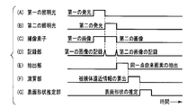
- an embodiment according to the present invention includes a light source device that includes a first irradiation window that irradiates first illumination light and a second irradiation window that irradiates second illumination light.
- the light source device includes the first illumination light and the second illumination light.
- the first illumination light and the second illumination light have substantially the same optical characteristics, and the imaging device includes the first and second illumination lights.
- the observation system compares the first optical information and the second image with the optical information recording unit that records the first optical information and the second optical information, and the same point on the subject.
- a calculation unit that calculates subject perspective information that is a relative distance relationship between the first identical point and the second identical point from the imaging device, and a surface shape that estimates the surface shape of the subject from the subject perspective information
- the observation system includes an estimation unit and a display unit that displays a stereoscopic image in which the surface shape estimated by the surface shape estimation unit is reflected.
- an uneven state on the surface of an object from a captured image captured under illumination light sequentially irradiated at successive timings from a plurality of irradiation windows at different positions arranged in parallel in one imaging optical system It is possible to provide an observation system capable of acquiring perspective information that suggests and displaying a three-dimensional observation image based on the perspective information.
- FIG. 1 is a diagram showing an overall configuration of an observation system according to the first embodiment of the present invention.
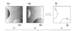
- FIG. 2 is a diagram for explaining pixels derived from the same point when the first image and the second image in which feature points are set are superimposed.
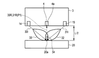
- FIG. 3 is a diagram illustrating a conceptual arrangement example in which the subject perspective information is acquired from the illumination light in a state where the observation system is close to the subject at the distance L1.
- FIG. 4 is a diagram illustrating a conceptual arrangement example in which the subject perspective information is acquired from the illumination light in a state where the observation system is remote from the subject at a distance L2.
- FIG. 5 is a diagram conceptually showing the level of light reflected from the flat surface when the subject is irradiated with the first illumination light and the second illumination light.
- FIG. 6 is a diagram illustrating the relationship between the amounts of light in the two reflected lights when the distal end surface of the insertion portion and the surface of the subject are inclined and face each other.
- FIG. 7 is a diagram conceptually illustrating the inclination of the surface of the subject according to the ratio of the amount of reflected light between the first illumination light and the second illumination light.
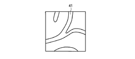
- FIG. 8A is an image diagram showing an observation screen of a two-dimensional image of a subject imaged by the observation system before perspective enhancement.
- FIG. 8B is an image diagram showing an observation screen of a three-dimensional image after perspective enhancement of the subject imaged by the observation system of the present embodiment.
- FIG. 9 is a flowchart for explaining display of perspective (unevenness) emphasis.
- FIG. 10 is a timing chart for explaining the display of perspective (unevenness) emphasis.
- FIG. 11 is a diagram illustrating a conceptual arrangement example of the observation system according to the second embodiment.
- FIG. 12 is a diagram illustrating a conceptual arrangement example in which the object perspective information is acquired from the illumination light in a state where the observation system is remote from the object at a distance L.
- FIG. 13 is a conceptual diagram for explaining the relationship between the distance and the amount of received light.
- FIG. 14 is a conceptual diagram of an image including the same points for explaining the features of the observation system according to the third embodiment.
- FIG. 15 is a conceptual diagram for explaining obtaining subject perspective information from a plurality of illumination lights irradiated from three or more irradiation windows.
- FIG. 1 shows the overall configuration of an observation system 1 according to the first embodiment of the present invention.
- FIGS. 2A, 2 ⁇ / b> B, and 2 ⁇ / b> C are diagrams for explaining the same point pixels (pixels derived from the same point) when the first image and the second image are overlaid.
- the observation system 1 can be implemented alone or incorporated into a device having other functions.
- an example is proposed in which the components of the observation system are incorporated into an endoscope insertion portion and a light source device or a video processor.
- the component part of an endoscope has a function equivalent to the component part of the observation system 1, you may share with the component part by the side of an endoscope.
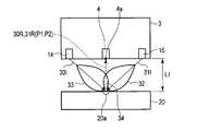
- the observation system 1 is broadly divided into a light source unit (light source device) 3 that irradiates illumination light from the distal end of the insertion portion 2 of the endoscope, an image pickup device 4 that is a light receiving portion and generates an image pickup signal, and an image pickup device 4.
- the three-dimensional image generation unit 5 that estimates the surface shape of the observation location (or the same point to be described later) 20a of the subject 20 from the imaging signal output from the image, and the observation location estimated by the three-dimensional image generation unit 5 from the surface shape
- a display unit (an endoscope monitor unit) 6 that displays image information including a three-dimensional image.
- the light source unit 3 includes a plurality of irradiation windows 12 and 13 disposed on the distal end surface 2 a of the insertion portion 2, a plurality of light conversion units 14 and 15 disposed in the insertion portion 2, and an outside of the insertion portion 2.
- the light emission control unit 7 is configured.
- the light emission control unit 7 may be incorporated in an endoscope light source device.
- the three-dimensional image generation unit 5 includes a control unit 21 that controls the entire observation system, an image processing unit 22, image data (images and information related to the images), optical information (amount of light (luminous intensity), imaging pixel address information, and the like).
- Recording unit optical information recording unit
- same-point origin pixel extracting unit hereinafter referred to as an extracting unit
- arithmetic unit 25 for calculating subject perspective information indicating the uneven state of the subject
- a surface shape estimation unit 26 that estimates the surface shape of the subject from the subject perspective information.
- the image processing unit 22 converts the imaging signal captured by the imaging device 4 into image data, and generates various information including optical information from the image data.
- the extraction unit 24 sets feature points 20a (same points XA and XB, which will be described later) on the subject for obtaining the positional relationship of the subject in the image, at portions common to at least two images, Pixels (or picture elements) that are feature points are set as image pixels derived from the same point (hereinafter referred to as “same point pixels”).
- the pixel of the image sensor that captures the same point image pixel on the image is referred to as the same point image pickup pixel (hereinafter referred to as the same point image pickup pixel 4a).
- the calculation unit 25 calculates subject distance information that is a relative distance relationship from light amount information (one of optical information) of pixels of an image captured by the image sensor 4.
- the surface shape estimation unit 26 estimates the surface shape (uneven shape) of the observation location of the subject from the subject perspective information.
- the same point here means that when a common subject is imprinted over a plurality of images, each of the images taken when a certain part of the subject image is arbitrarily determined as the feature point 20a.
- the feature points that match in the image are the same point.
- the images corresponding to these same points they are called the same point pixels (XA, XB shown in FIG. 2).
- the same point pixel A plurality of image pickup pixels 4a for picking up images are extracted, and address information of these image pickup pixels is output as one of optical information in association with image data. A signal indicating the light quantity of these same point pixels is generated, and subject perspective information is calculated.
- the feature points and the same points are referred to as points, but actually suggest a minimum feature region on the surface of the subject.
- the same point pixel is not limited to one pixel, but includes a small group of pixels or a plurality of pixels forming a small image area.
- the first irradiation window 12 and the second irradiation window 13 are disposed in the vicinity of the light receiving window 11 disposed in the vicinity of the center of the distal end surface 2a of the insertion portion 2.
- the observation window of the observation device that serves as the objective lens of the image sensor is also used as the light reception window of the endoscope, and hence is referred to as the light reception window in the following description.
- the illumination window which performs illumination at the time of observation of the observation apparatus is also used as the irradiation window of the endoscope, it is referred to as an irradiation window in the following description.
- the light receiving window 11, the first irradiation window 12, and the second irradiation window 13 are all attached to the distal end surface 2a in a watertight manner using a waterproof member such as a packing member.
- the first irradiation window 12 and the second irradiation window 13 are symmetrically arranged on the distal end surface 2a with the light receiving window 11 as the center and at substantially the same distance in the diameter direction.
- the plurality of irradiation windows may irradiate light of the same luminous intensity (light quantity) to the same point of the subject (for example, the center of the imaging field) or the observation range.
- the distance to the light receiving window 11 on the surface can be adjusted, and is not limited to the symmetrical arrangement shown in FIG.
- the first light conversion unit 14 is disposed in close contact with or close to the first irradiation window 12, and the second light conversion unit 15 is disposed in close contact with or close to the second irradiation window 13.
- the excitation light (optical signal) described later is converted into illumination light.
- the irradiation window of the present embodiment is a lens function that optically adjusts so that the illuminated illumination light 30I, 31I is uniformly diffused within the imaging field of view and a constant luminous intensity (light quantity) is distributed. have.
- an optical member (not shown) that performs the optical adjustment as described above may be separately provided between the irradiation window and the light conversion unit.
- the light conversion units 14 and 15 are provided with phosphors as wavelength conversion members at the tips of the optical fibers 16 and 17.
- the light emission control unit 7 includes a light source that emits excitation light, and emits excitation light to the first light conversion unit 14 and the second light conversion unit 15 through the optical fibers 16 and 17.
- the first light conversion unit 14 and the second light conversion unit 15 convert light having a wavelength different from the received excitation light into illumination light 30I and 31I from the first and second irradiation windows 12 and 13, respectively. Irradiates the observation target.
- the light emission control unit 7 is equipped with two blue semiconductor laser light sources that emit light of the same wavelength. These blue semiconductor laser light sources are continuously switched by alternately switching the first excitation light guided to the first light conversion unit 14 and the second excitation light guided to the second light conversion unit 15. Can be irradiated.
- the blue laser light that is the first and second excitation light emitted from the blue semiconductor laser light source is respectively converted into first and second light conversion units by optical fibers 16 and 17 that are, for example, multimode optical fibers. 14 and 15 are guided.
- the illumination light whose wavelength is converted from the laser light is emitted from the first irradiation window 12 as the first illumination light 30I, and is emitted from the second irradiation window 13 as the second illumination light 31I.
- the first illumination light 30I and the second illumination light 31I are emitted at different timings.
- a combination of one blue semiconductor laser light source and an optical switching unit can be switched to two optical fibers. It is also possible to introduce excitation light.
- both the first illumination light 30I and the second illumination light 31I are white light that is a mixed color of blue laser light and yellow fluorescence wavelength-converted by the light conversion units 14 and 15. Are combined, and have substantially the same optical characteristics.
- the light emission control unit 7 can control the output (output light amount) of the laser light source to adjust to substantially the same optical characteristics.
- an optical sensor (not shown) may be provided, or feedback control may be performed using a signal value for driving the image sensor 4.
- the first illumination light 30I irradiated from the first light conversion unit 14 is irradiated onto the subject 20, where it is reflected and scattered, and a part thereof becomes reflected light 30R and enters the imaging device 4.
- the second illumination light 31I irradiated from the second light conversion unit 15 is irradiated onto the subject 20, where it is reflected and scattered, and part of the second illumination light 31I becomes reflected light 31R. Incident.
- the observation system 1 is an example applied to an endoscope, and is therefore an application for observing the inside of a body cavity with almost no external light.
- the first illumination light 30I and the second illumination light 31I Except for the reflected lights 30R and 31R, the image pickup element 4 is hardly incident. Therefore, the imaging device 4 can capture the first image by only the reflected light 30R of the first illumination light 30I and the second image by only the reflected light 31R of the second illumination light 31I.
- the imaging device 4 used in the present embodiment is a spectrally detectable color imaging device in which a plurality of pixels form a light receiving surface in a matrix arrangement, and an RGB primary color filter having, for example, a normal Bayer array is provided on the light receiving surface. That is, it is a spectral detection imaging device.
- the image processing unit 22 extracts the first optical information as one of the image information from the first image captured under the first illumination light, and similarly, the first optical information captured under the second illumination light. Second optical information is extracted from the second image as image information, and is stored in the recording unit 23 in association with the image.
- the first and second optical information here is light amount information for each wavelength region of RGB detected by the image sensor 4.
- the first and second optical information is light amount information (including pixel address information) for each RGB color pixel of the image sensor 4, but is not limited thereto.
- information on the image sensor and information obtained by processing them are included.
- the extraction unit 24 compares the first image and the second image, and specifies the same point pixel which is the same point (same feature point) 20a on the subject 20, respectively. For example, in a plurality of captured images, when the same subject is captured with substantially the same composition, a plurality of feature points (same points 20a) common to each image are set, and the feature points are overlapped. By combining them, one superimposed image is formed. That is, the same point pixel is determined between images captured under illumination light irradiated from different positions.
- the first identical point pixel (XA1 in FIG. 2A) on the first image is a pixel that detects the first optical information at the same point, and is on the second image.
- the first identical point pixel (XA2 in FIG. 2B) is a pixel that detects the second optical information at the same common point of the same subject. If a plurality of J (J: integer) identical points are set in one image, there are J identical point pixels corresponding to the number. For example, if three identical points are set in one image, three identical point pixels corresponding to the plurality of identical points exist. The subject perspective information described later is calculated from these same point pixels.
- the extraction unit 24 compares the first image and the second image to identify the same point on the image.
- Various methods can be applied to specify the same point. As an example, when the position of the subject is shifted between two images captured by one image sensor, image processing for extracting a common feature point (same point) of the subject on each image is performed. . As shown in FIG. 4C, which will be described later, by specifying the positional relationship between two images so that their feature points overlap, the same point between the two images can be specified, and the corresponding imaging The same point pixel of element 4 is selected.
- the light emission timings of the first illumination light and the second illumination light are switched at a timing sufficiently earlier than the moving speed of the distal end surface 2a of the insertion portion 2, so that the light is continuously moved with little movement. And imaged. Moreover, since the front end surface 2a is moved while observing, the moving speed is generally slow. Therefore, in the captured image, the same point of each subject is substantially the same in the pixel position on the first image and the pixel position on the second image.
- the same point pixel (primary same point derived pixel) when the first image and the second image are overlaid will be described.
- the first image and the second image that are continuously captured in a short time are two images that are captured at substantially the same position of the image sensor with respect to the subject. For this reason, as shown in FIGS.
- At least two sets of feature points are both When extracted as the same point, the first image and the second image are arranged so that these two sets of feature points (XA1 and XA2, XB1 and XB2) overlap.
- the two overlapping images are the same subject with almost the same composition, these feature points also coincide and overlap two points (XA, XB) as shown in FIG. Therefore, in the superimposed image, all feature points can be set as the same point of the two images, and pixels that capture the same point are the same point pixels.
- the pixels that respectively capture the feature points XA1, XB1, XA2, and XB2 are the first image first point pixel (XA1), the first image second point pixel (XB1), and the first point of the second image.
- Pixel (XB2) and second image second The same point image (XB2) is used.
- J integer
- the calculation unit 25 compares and calculates the first optical information of the first image output from the extraction unit 24 and the second optical information of the second image, and the same as the subject that is the feature point.
- One point (or any measurement site) is extracted.
- extraction is performed based on light amount information, which is one of the optical information of the same point pixels of the first and second images.
- a feature point detection method used in a known image pasting method can be used.
- a detection method for example, on one image, a pixel group composed of feature pixels and its peripheral pixels is set, and a pattern based on the image signal value or light amount value is generated. Pattern detection that searches for matching pixel groups is also one of the techniques.
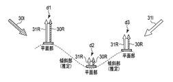
- FIG. 3 is a diagram illustrating a conceptual arrangement example in which the observation system 1 acquires subject perspective information from illumination light in a state in which the observation system 1 is close to the subject 20 at a distance L1.
- FIG. 4 is a diagram illustrating a conceptual arrangement example in which the subject perspective information is acquired from the illumination light in a state where the observation system 1 is remote from the subject 20 at a distance L2.
- FIG. 5 is a diagram conceptually showing the level of light reflected from the flat surface when the subject is irradiated with the first illumination light and the second illumination light.
- one light ray of the diffused light of each white illumination light is indicated by a solid line and a dotted line.
- light distributions (light distribution information) 32 and 33 forming a drop shape along the optical axis of the reflected light 30R and 31R are shown on the reflection side that is line-symmetric with the incident angles of the illumination lights 30I and 31I. Yes.
- This light distribution information is the relationship between the irradiation direction of the light source and the light intensity, and is recorded in the recording unit 23 as one piece of information regarding the image.
- the calculation unit 25 uses the received light amount P1 (reflected light 30R) as light amount information in the first image and the light amount information in the second image for the same point pixel associated with the extracted same point 20a.
- a certain amount of received light P2 (reflected light 31R) is extracted, and light quantity ratio information P1 / P2 which is a ratio thereof is obtained.
- this light quantity ratio information P1 / P2 the light emitted from the first irradiation window 12 is reflected and scattered at the same point 20a, and the light quantity incident on the image sensor 4 and the light emitted from the second irradiation window 13 are the same. It is a ratio to the amount of light reflected at the same point and incident on the image sensor.
- grouping is performed for each pixel at the same point based on the light quantity ratio information P1 / P2.
- the ratio of the light quantity ratio information P1 / P2 is “1” (absolute value) or “substantially 1” in the second group, that is, the same light quantity pixels in which two identical pixels have the same light quantity ratio. If there is, as shown in FIG. 5, the same point on the surface of the subject faces the tip surface (plane) of the insertion portion 2 where the irradiation window is arranged in parallel, and the surface It is estimated that the same point is a plane part.
- the light amount ratio can estimate whether or not the surface is flat, but it cannot estimate the distance with respect to the distance because it is not the magnitude of the light amount.
- the height of these flat portions that is, the distance from the image sensor 4 to the subject can be calculated from the amount of light detected by the image sensor 4 using the aforementioned triangulation method or the like.
- the calculating unit 25 compares the magnitude relation of the plurality of identical points 20a included in the second group of the equal light quantity ratio information P1 / P2 ⁇ 1 by the absolute value of the light quantity at P1 ( ⁇ P2).
- the magnitude of the light quantity P1 ( ⁇ P2) is related to the distance between the imaging element 4 and the same point 20a on the subject 20. That is, when the magnitude relationship of P1 ( ⁇ P2) is compared, it can be seen that the same point d1 having a larger light amount is closer to the image sensor 4 than the smaller same point d2, and the distance L is shorter.
- the calculation unit 25 calculates subject perspective information that is a relative distance relationship from the image sensor 4 to the subject 20 based on the amount of light detected by the image sensor 4. Furthermore, the surface shape estimation unit 26 estimates the uneven state of the observation location of the subject from the subject perspective information and the image associated with the same point read from the recording unit 23, and the perspective (unevenness). A three-dimensional image is formed by enhancement.
- the light distribution information obtained when the light irradiated from the illumination light hits a substance (for example, a surface tissue or the like) and reflects is used, and data stored in the recording unit is used. This light distribution information is detected and accumulated in advance for data on each substance (including blood vessels) that can be measured.
- the distribution of reflected light from the illumination light is also tilted, and the intensity of the amount of light received by the image sensor changes, so that the part (substance) is tilted. It can be recognized, and surface irregularities can be corrected from the relationship with adjacent pixels.
- the plane portion d1 is higher than the plane portion d2 on the top side due to the difference in the amount of light detected by the imaging device 4, and between the plane portion and the plane portion.
- the plane part d1 and the plane part d2 it has a concavo-convex state in which the plane part d2 is on the bottom side, and it is estimated that the part is connected by an inclined part.
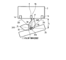
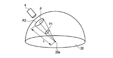
- FIG. 6 is a diagram illustrating the relationship between the amounts of light in the two reflected lights when the distal end surface 2a of the insertion section 2 and the surface of the subject 20 are inclined and face each other.
- FIG. 7 is a diagram conceptually illustrating the inclination of the surface of the subject according to the ratio of the amount of reflected light between the first illumination light and the second illumination light.
- the ratio of the reflected and scattered light amount of the subject 20 is the imaging field of view direction of the imaging device 4. It changes depending on the incident direction of the illumination light with respect to the observation axis (arrow 34 in FIG. 6).
- the observation axis is a perpendicular to the observation direction of the image sensor, generally the tip plane. How much the observation surface of the subject is inclined with respect to this observation axis is expressed as an observation axis inclination angle.
- the reflected light amount of the first illumination light is greater than the reflected light amount of the second illumination light. Becomes smaller.
- the reflected light 30R of the first illumination light 30I enters the light receiving surface of the image pickup element 4 with a portion where the light amount of the light distribution is increased close to the observation axis 34.
- the reflected light 31R of the second illumination light 31I is incident on the image sensor 4 with the portion of the light distribution in the light distribution distribution being increased away from the observation axis 34 by increasing the reflection angle.
- the light quantity 32 of the 1st reflected light 30R light-received by the image pick-up element 4 by the inclination becomes larger than the light quantity 33 of the 2nd reflected light 31R. That is, P1 and P2 are different, and P1 / P2 is other than 1.
- the calculation unit 25 sets the light amount ratio information P1 / P2 ⁇ 1 as the same point 20a on the plane portion of the subject, that is, pixels having substantially the same P1 and P2 (assuming the same light amount). Extract as a second group. Further, the plane portion of the subject is estimated from the first subject perspective information obtained from the second group of pixels. Further, as shown in FIG. 7, by obtaining long-distance information even when the equal light ratio pixel is different from 1/1, for example, at 1/2 location, 1/2 location can also be obtained at 1/1 location. In addition, more detailed long-distance information can be acquired.
- the calculation unit 25 sets a plurality of identical points 20a on all or a part of the surface of the subject for pixels excluding the second group of pixels. Using the light quantity of the same point pixel at the same point 20a that has been imaged, second object perspective information that is a relative distance relationship is calculated.
- the plane estimated by the second object perspective information does not include the second group of pixels, that is, does not include the plane portion of the object 20, and thus is inclined in any direction. It turns out that it is an inclined part.
- the planar portion and the planar portion of the second group are smoothly connected by the inclined portion obtained from the second subject perspective information, and the uneven state of the subject is estimated as shown in FIG. be able to.
- the surface shape estimation unit 26 reads the image recorded in the recording unit 23, reflects the calculated subject perspective information on the entire image or a part thereof, and emphasizes the perspective (uneven shape). A three-dimensional image of the three-dimensional image is formed and output to the display unit 6.
- FIG. 8A is an image diagram showing an observation screen of a two-dimensional image before perspective enhancement of a subject imaged by an endoscope equipped with an observation system
- FIG. 8B is a three-dimensional image generation of this embodiment.
- 6 is an image diagram showing an observation screen of a three-dimensional image after perspective enhancement of a subject imaged by an endoscope equipped with an observation system 1 having a unit 5.
- FIG. 8B the portion 42a in which the unevenness is emphasized and the portion 42b before the unevenness enhancement that cannot be confirmed in FIG. 8A are easily visible.
- Such a three-dimensional image display can give the operator and observer a sense of distance and a three-dimensional feeling between the parts, and can reduce the burden on the grasping and treatment operations of the treatment target part.
- diagnosis and judgment at the time of observation can be assisted.
- the received light amounts P1 and P2 of the first and second images are P1-R
- Information on P1-G, P1-B, P2-R, P2-G, and P2-B can be detected. What added these for every P1 and P2 may be used as light quantity information.
- information on a color pixel having a high spectral reflectance of the subject may be used.
- the values of P1-R and P2-R are larger than the light amount information of other colors. Therefore, by using only the red light quantity information, it is possible to obtain more accurate subject perspective information.
- spectral reflectance information for a substance such as an internal blood vessel or a surface layer tissue to be measured, a measurement value measured in advance or a numerical value disclosed in literature is acquired as spectral reflectance information and stored in the recording unit 23. deep. Comparing the spectral reflectance information of the part (or substance) obtained by actual measurement with the spectral reflectance information stored in the recording unit 23, for example, estimating whether it is the surface or the inside, and correcting the perspective information Is possible.
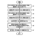
- the light emission control unit 7 controls the irradiation timings of the first light conversion unit and the second light conversion unit to be different.
- the light emission control unit 7 irradiates the observation portion of the subject 20 with the first illumination light 30I [FIG. 10A], and the imaging device 4 receives the reflected light 30R from the subject 20.
- the first imaging signal is output to the image processing unit 22 [FIG. 10C] (step S1).
- the image processing unit 22 calculates the first reflected light amount by the reflected light received from the first imaging signal, and records the first reflected light amount together with the image data in the recording unit 23 [FIG.
- the light emission control unit 7 irradiates the observation portion of the subject 20 with the second illumination light 31I [FIG. 10B], and the imaging device 4 receives the reflected light 31R from the subject 20.
- the second imaging signal is output to the image processing unit 22 [FIG. 10C] (step S3).
- the image processing unit 22 calculates the second reflected light amount by the reflected light received from the second imaging signal, and records it in the recording unit 23 together with the image data [FIG. 10D] (step S4).
- the extraction unit 24 compares the pixel of the first reflected light amount image read from the recording unit 23 with the pixel of the second reflected light amount image, and extracts the same point pixel in the observation location.
- the calculation unit 25 calculates the subject perspective information for the observation location (planar portion) where P1 / P2 ⁇ 1, which is the ratio of the extracted light amount information of the same point pixels [FIG. 10 (F)]. Further, the above-described inclined portion may be calculated continuously.
- the surface shape estimation unit 26 estimates the surface shape of the observation location of the subject from the calculated subject perspective information [FIG. 10 (G)], and unevenness enhancement is performed on the image read from the recording unit 23.
- the image processing is performed (step S6).
- the display unit 6 displays an image of the observation location with the unevenness enhanced (step S7).
- the illumination light is irradiated to the subject at different light emission timings from a plurality of light sources that are equidistant from one image sensor, and the images are captured with the respective reflected light amounts.
- the same part of at least one subject is specified, and the ratio of the reflected light of each light source (first reflected light quantity / second reflected light quantity) in each part is substantially equal.
- the perspective information of the subject is acquired based on the absolute value of the ratio. Even if the surface of the part is wet with mucus and diffusely reflected, it can be recognized that the parts having the same reflection spectrum from two or more different light sources are the same plane.
- the light quantity ratio (first reflected light quantity / second reflected light quantity) is measured by measuring the relationship between the slopes of substantially the same part or different parts, and specifying the slope of the slope based on the magnitude of the light quantity ratio.
- the perspective (unevenness) state of the subject can be estimated.
- the present embodiment conventionally, it is easy and reliable to disperse various pigments and to disperse pigments for scenes where a “pigment method” for observing the reaction is necessary. Perspective (unevenness) emphasis can be realized. Since the coloring agent is not sprayed, normal observation of the original tissue can be continued, and since there is no major change in the usage and structure of existing endoscopes, it is also excellent in terms of reliability and cost. .
- the same point pixel (the same point derived pixel) is defined as one pixel of the image sensor, but is not limited to one pixel.
- the sum of the light amount information detected by the individual pixels constituting these pixel groups is defined as the light amount information detected by the pixel group.
- the same subject perspective information is obtained by using the sum of only individual pixels having the same spectral region as the light amount information detected by the pixel group. And the surface shape of the subject can be calculated and estimated.
- the positional relationship of the end faces of the first irradiation window, the second irradiation window, and the image sensor is an embodiment in which the first irradiation window and the second irradiation window are arranged symmetrically at equal intervals around the image sensor.
- the imaging element is shifted from the axis connecting the first irradiation window and the second irradiation window, the ratio of the amount of light irradiated from the first irradiation window and the second irradiation window, the first The image may be acquired by correcting the relationship between the distances between the irradiation window, the second irradiation window, and the imaging element.
- the calculation unit 25 detects the first reflected light amount and the second reflected light amount with the image sensor 4 when calculating subject perspective information that is an uneven shape of the subject 20.
- the inclination of the surface shape of the subject 20 with respect to the flat light receiving surface of the image sensor 4 is used as inclination information obtained by sequentially connecting the light quantity values output from adjacent pixels, and the image is obtained from the perspective (based on the inclination information). It is also possible to create and display a three-dimensional image by performing image processing on the (unevenness) emphasized image.
- the type of the subject 20 having the same color information can be specified from the color information such as the RGB ratio of each pixel, and the accuracy of the part information can be improved.
- the image sensor is not limited to an RGB light source, for example, an image sensor 4 provided with no color filter and an image sensor using a surface sequential method that alternately emits R light, G light, and B light from two irradiation windows. 6 images (first R light image, second R light image, first G light image, second G light image, first B light image, second B light image) obtained by 4 Using the combination, the type of the subject 20 can be specified from these color information, and the accuracy of the part information can be improved.
- pixels with the same light amount that have a light amount ratio P1 / P2 ⁇ 1 are used as observation locations, but pixels with different light amounts of P1 / P2 ⁇ ( ⁇ is a predetermined positive number). Can be used.
- the surface orthogonal to the observation axis is the observation location.
- a surface having an arbitrary inclination angle with respect to the observation axis is extracted as the observation location.
- FIG. 11 is a diagram illustrating a conceptual arrangement example in which the observation system 1 according to the second embodiment acquires subject perspective information from illumination light in a state in which the observation system 1 is close to the subject 20 at a distance L / 2.
- FIG. 12 is a diagram illustrating a conceptual arrangement example in which the subject perspective information is acquired from the illumination light in a state where the observation system 1 is remote from the subject 20 at a distance L.
- the subject perspective information is calculated according to the magnitude relationship of the amount of received light with respect to pixels having the same light amount (pixels derived from the same point) satisfying P1 / P2 ⁇ 1.
- the amount of reflected light P1 increases in proportion to the distance.
- FIG. 11 shows an example in which the distance between the image sensor 4 and the subject 20 is L / 2.
- the amount of reflected light P2 is also reduced in proportion to the distance.
- FIG. 12 shows an example in which the distance between the image sensor 4 and the subject 20 is L, for example.
- the received light amount received by the same light quantity pixel is the same point on the imaging element 4 and the subject 20. It becomes smaller in inverse proportion to the square of the distance to 20a.
- the distance can be calculated as a value proportional to the reciprocal of the square root of the amount of light received by the same light quantity pixel. For example, when the distance L is doubled, the amount of light that can be measured is 1 ⁇ 4. If the amount of light is regarded as a flat area, the amount of light that can be received by the imaging element 4 having a finite size has an inversely proportional relationship with the distance.
- the observation system according to the third embodiment is an observation system in which the light source unit has three or more irradiation windows. Components other than the light source unit of the present embodiment are the same as those of the first embodiment, and the same components are denoted by the same reference numerals and description thereof is omitted.
- the light source unit 3 of the present embodiment shown in FIG. 14 has a configuration example in which three irradiation windows 13, 14, 51 are arranged on the distal end surface 2 a of the insertion portion 2 at an equal distance with one light receiving window as the center. It is. Among these three irradiation windows 13, 14, 51, two appropriate irradiation windows are selected, and a three-dimensional imaging process equivalent to that in the first embodiment described above is performed. Further, as shown in FIGS. 15 (a), (b), and (c), with respect to a plurality of illumination lights irradiated from three or more irradiation windows, the respective light quantity information is used and the above-described method is used. It is also possible to obtain the subject perspective information of FIG.
- the three irradiation windows 13, 14, 51 and the imaging device 4 are defined.
- the configuration having only two irradiation windows can detect the relative distance information in the arrangement direction of the light source with high accuracy, but with respect to the direction orthogonal thereto. Although the accuracy slightly decreases, the configuration having three or more irradiation windows can detect the relative distance information with high accuracy in all directions.
- the present embodiment by selecting two appropriate irradiation windows among these three irradiation windows 13, 14, 51, the same effects as those of the first embodiment described above can be obtained. Obtainable. Further, by adding the third irradiation window 51, the number of images captured under illumination light irradiated from different directions (y) increases, and more subject perspective information can be acquired. A detailed three-dimensional image can be estimated.
- the observation system is configured to arrange four or more irradiation windows.
- the configuration example can be realized by the configurations shown in FIGS. 1 and 14 except for a configuration in which a plurality of illumination windows are arranged and the illumination light is irradiated to each.
- an image of the subject 20 is picked up through one light receiving window 11 in which the image pickup device 4 is arranged.
- a plurality of irradiation windows are arranged in the vicinity of the light receiving window 11 as a substantial center.
- the light emission control unit 7 selectively and sequentially irradiates the subject 20 with illumination light having the same optical characteristics generated by the light source device from a plurality of irradiation windows.
- the imaging element 4 captures a plurality of images captured for each illumination light under illumination light that is selectively and sequentially irradiated, and outputs the captured images to the image processing unit 22 as imaging signals.
- the image processing unit 22 generates optical information included in each image, and records the optical information in the recording unit 23 in association with the image.
- the same-origin pixel extraction unit 24 reads a plurality of images from the recording unit 23 under the control of the control unit 21 and sequentially sets the same feature points (such as XA) on the subject 20 as the same points. Specifically, at least two provisional feature points are set on one image, and it is confirmed whether or not provisional feature points exist for all other images. When temporary feature points exist in all images, these temporary feature points are set to the same point. If the temporary feature point does not exist in all the images, the temporary feature line is reset and the existence is confirmed. Feature points existing in all images are set as the same point.
- the same feature points such as XA
- one image be a reference image, and at least two identical points be reference identical points.
- Each image is subjected to image superimposition processing by moving the entire image so that the two identical points are positioned at the reference identical point. Pixels obtained by imaging the same point are extracted as pixels derived from the same point, and are output to the calculation unit 25 together with the light amount value output by the pixel.
- the calculation unit 25 calculates subject perspective information using the light amount value included in the optical information output by the same point imaging pixel as a relative distance from the imaging element 4 and outputs the object perspective information to the surface shape estimation unit 26.
- the light amount value of the same point pixel in the captured image may be output from the recording unit 23 to the calculation unit 25.
- the surface shape estimation unit 26 compares the optical information output from the plurality of identical point-derived pixels obtained by imaging the plurality of identical points common to the images between the paired images. The same point with the comparison result of approximately 1 is determined as the plane portion, the same point with the comparison result exceeding approximately 1 is determined as the first inclined portion, or the same point with the comparison result less than approximately 1 is determined as the second inclined portion. Based on these determinations, the surface shape of the subject is estimated by associating the relative distance previously obtained with the plane portion and the first and second inclined portions.
- the display unit 6 displays a three-dimensional image with the surface shape estimated by the surface shape estimation unit.
- two images (images A and B) captured under illumination by two arbitrary illumination windows arranged on both sides of the light receiving window are set as a first pair of images.
- a second pair of illumination windows arranged on a straight line in an arbitrary direction that intersects the direction of the straight line connecting the positions of these two illumination windows is selected, and two images (images taken under these illuminations) Let C, D) be a second pair of images.
- a plurality of identical points are set with the same feature point (XA, etc.) on the subject 20 being imaged in each image of these pairs as the same point, and pixels that have imaged those same points are derived from the same point.
- the pixel is extracted and output to the calculation unit 25 together with the light amount value output by the pixel. Subsequent calculation of the subject perspective information by the calculation unit 25 and estimation of the surface shape of the subject by the surface shape estimation unit 26 are equivalent to the above-described modification.
- the observation system is configured to arrange three or more irradiation windows, by combining with the first and second embodiments, more accurate subject perspective information while maintaining its effect, and It is possible to obtain the above-described various information required therefrom.
- the embodiment and the modification described above are merely examples, and various modifications can be made without departing from the spirit of the invention.
- the embodiment described above includes the gist of the following invention.
- an image pickup device for picking up an image of a subject taken from the light receiving window;
- a first irradiation window that is disposed in the vicinity of the light receiving window, irradiates the subject with first illumination light, and a position that is symmetrical to the position of the first irradiation window with respect to the light receiving window.
- a second irradiation window for irradiating the subject with the second illumination light having the same optical characteristics as the first illumination light, and light emission for emitting the first illumination light and the second illumination light at different timings A light source device comprising: a control unit; The image sensor captures a first image of the subject imaged under the first illumination light and a second image of the subject imaged under the second illumination light, An image processing unit for generating first optical information included in the first image and second optical information included in the second image; A recording unit that records the first optical information and the second optical information in relation to the image output by the image processing unit; The first image and the second image are compared to find a plurality of the same feature points on the imaged subject as the same point, and the same point on the first image is found as the first image.
- the same point-derived pixel extraction unit that extracts the same point on the second image as the second image same point-derived pixel as the same point-derived pixel; For the first identical point and the second identical point set out of a plurality of identical points on the subject extracted by the identical point-derived pixel extraction unit, First optical information of the first image first identical point derived pixel at the first identical point, second optical information of the second image first identical point derived pixel, The first optical information of the first image second identical point-derived pixel at the second identical point is compared with the second optical information of the second image second identical point-derived pixel, respectively, A computing unit that calculates subject perspective information that is a relative distance relationship between the first identical point and the second identical point on the subject from the imaging device; A surface shape estimation unit that estimates the surface shape of the subject based on the subject perspective information; A display unit for displaying as a stereoscopic image by the surface shape estimated by the surface shape estimation unit; An observation system comprising:
Abstract
Provided are one imaging optical system, and an observation system which acquires, from captured images captured under illumination light applied at different timings from a plurality of irradiation windows, perspective information that suggests the uneven state of the surface of a subject, and displays a three-dimensional observation image.
An observation system captures images of a subject under illumination light applied at different timings from a plurality of irradiation windows disposed near one imaging element, generates optical information included in each of the images, calculates, as a relative distance from the imaging element, the value of a light quantity included in the optical information outputted from a same point-derived pixel obtained by capturing an image of the same point that is the same feature point on the subject within each of the images, compares the optical information between the images, determines the same point of the subject as a planar part or an inclined part according to the result of the comparison, associates the distance with the planar part or the inclined part to estimate the surface shape of the subject, and displays a three-dimensional image of the subject.
Description
本発明は、被検体の同一観察箇所に対する複数回の発光による各撮像画像から算出した遠近情報に基づく被検体の表面形状を推定し立体画像として表示する観察システムに関する。
The present invention relates to an observation system that estimates a surface shape of a subject based on perspective information calculated from each captured image by light emission a plurality of times with respect to the same observation location of the subject and displays it as a stereoscopic image.
一般的に、立体画像(3次元画像)をモニタ表示する場合は、視点の差(両眼視差)を有する2つの撮像系を用いて、それぞれに撮像した画像を合成して表示している。撮像素子を搭載する内視鏡等に適用される観察装置においては、処置具が取り付けられたアームを用いる内視鏡手術を実施する際に、処置対象となる被検体の表面の凹凸状態をわかりやすく立体的に表示する3次元表示が望まれている。
Generally, when a stereoscopic image (three-dimensional image) is displayed on a monitor, two captured images having a difference in viewpoint (binocular parallax) are used to synthesize and display the captured images. In an observation apparatus applied to an endoscope or the like equipped with an imaging device, when performing an endoscopic operation using an arm to which a treatment tool is attached, the unevenness state of the surface of the subject to be treated is known. A three-dimensional display that easily displays in three dimensions is desired.
被検体表面の凹凸状態を表示するために必要な遠近情報は、例えば、光を測定箇所に照射し、その反射光を撮像素子に取り込み、受光面の結像位置から観察箇所までの距離として算出する所謂、三角測距方式を用いることにより取得し、この遠近情報から観察箇所の凹凸状態を算出できることが知られている。
Perspective information necessary to display the uneven state of the subject surface is calculated as the distance from the imaging position of the light receiving surface to the observation location by, for example, irradiating the measurement location with light and capturing the reflected light into the image sensor It is known that it is obtained by using a so-called triangulation method, and the uneven state of the observation location can be calculated from this perspective information.
しかし、内視鏡等の観察システムにおいては、挿入部は細径化が望まれており、その先端面には、鉗子孔等も加わり、複数の撮像光学系(複眼)を配置するほどの配置スペースがないため、1つの撮像光学系による3次元画像の構築が望まれている。例えば、引用文献1においては、1つの撮像光学系に対して、1つの光源を移動させて異なる位置から同一光度の拡散光を不動な観察箇所にそれぞれに照射し、取得した複数の撮像画像の輝度分布を測定し、測定箇所表面の距離分布を算出して、観察箇所の凹凸状態を計測する計測方法が提案されている。ここでは、輝度が光源から測定箇所までの距離の二乗に反比例することを利用して、光源から観察箇所表面までの距離を算出しており、複数の反射光による輝度分布から距離分布を算出している。
However, in an observation system such as an endoscope, the insertion portion is desired to have a small diameter, and a forceps hole or the like is added to the distal end surface thereof, so that a plurality of imaging optical systems (compound eyes) are arranged. Since there is no space, it is desired to construct a three-dimensional image with one imaging optical system. For example, in Cited Document 1, a single light source is moved with respect to one imaging optical system, and diffused light having the same luminous intensity is irradiated from different positions to each stationary observation location. There has been proposed a measurement method for measuring the luminance distribution, calculating the distance distribution on the surface of the measurement location, and measuring the uneven state of the observation location. Here, using the fact that the luminance is inversely proportional to the square of the distance from the light source to the measurement location, the distance from the light source to the surface of the observation location is calculated, and the distance distribution is calculated from the luminance distribution of multiple reflected lights. ing.
前述した特許文献1においては、距離分布は、観察対象が完全拡散反射面であることを想定した輝度分布により測定されている。しかしながら、内視鏡を使用する体腔内の環境では、観察箇所の表面が粘液で濡れているため、完全拡散反射面の環境ではなく、さらに表面の凹凸状態により、光が不均一な拡散反射(乱反射)する。このような拡散反射することで、観察箇所の表面の輝度が視点の角度によって異なってしまうため、輝度分布からは必ずしも正確な距離が算出されているとは限らない。また、特許文献1では、1つの光源を不動の被検体に対して、平行移動させて複数の点光源として使用することが提案されている。内視鏡においては、挿入部先端が湾曲動作により円軌道で移動するため、体腔内で挿入部先端を平行に移動させることは容易な操作ではなく、さらに、撮像部と照明部が一体で移動するため、接近して撮影している観察箇所が観察視野から外れてしまうことが懸念される。
In Patent Document 1 described above, the distance distribution is measured by a luminance distribution assuming that the observation target is a complete diffuse reflection surface. However, in the environment inside the body cavity using an endoscope, the surface of the observation site is wet with mucus, so that the light is not diffusely reflected due to unevenness of the surface, not the environment of the complete diffuse reflection surface ( Diffuse reflection). By such diffuse reflection, the brightness of the surface of the observation location varies depending on the angle of the viewpoint, and therefore an accurate distance is not always calculated from the brightness distribution. Further, Patent Document 1 proposes to use one light source as a plurality of point light sources by translating with respect to a stationary object. In an endoscope, the distal end of the insertion section moves in a circular orbit by a bending operation, so it is not easy to move the distal end of the insertion section in parallel within the body cavity, and the imaging section and the illumination section move together. For this reason, there is a concern that an observation spot that is being photographed close to the camera may be out of the observation field.
そこで本発明は、1つの撮像光学系に並設される異なる位置の複数の照射窓から、連続的なタイミングで順次照射された照明光下で撮像された撮像画像から被検体表面の凹凸状態を示唆する遠近情報を取得し、遠近情報に基づく3次元の観察画像を表示させることができる観察システムを提供することを目的とする。
In view of this, the present invention provides an uneven state on the surface of a subject from captured images captured under illumination light sequentially irradiated at successive timings from a plurality of irradiation windows at different positions arranged in parallel in one imaging optical system. It is an object of the present invention to provide an observation system capable of acquiring suggested perspective information and displaying a three-dimensional observation image based on the perspective information.
上記目的を達成するために、本発明に従う実施形態は、第1の照明光を照射する第1の照射窓と、第2の照明光を照射する第2の照射窓と、を有する光源装置と、前記第1、及び第2の照明光に照射された、被検体の画像を撮像する撮像素子と、を有する観察システムにおいて、前記光源装置は、第1の照明光と、第2の照明光とを、互いに異なるタイミングで発光させる発光制御部を有しており、前記第1、及び第2の照明光は、互いにほぼ等しい光学特性を有しており、前記撮像素子は、前記第1の照明光のみによる前記被検体の画像である第1の画像と、前記第2の照明光のみによる前記被検体の画像である第2の画像と、を取得可能であり、前記第1の画像は、第1の光学情報を、第2の画像は第2の光学情報をそれぞれ含んでおり、前記観察システムは、前記第1の光学情報と前記第2の光学情報を記録する光学情報記録部と、前記第1の画像と前記第2の画像を比較して、被検体上の同一点に由来する、第1の画像上の同一点由来画素である第1画像同一点由来画素と、第2の画像上の同一点由来画素である第2画像同一点由来画素とを対応付けて、被検体上の複数の同一点として、第1同一点と第2同一点を抽出する同一点由来画素抽出部と、を有し、さらに、前記第1同一点における第1画像第1同一点由来画素の有する第1の光学情報と、第2画像第1同一点由来画素の有する第2の光学情報と、前記第2同一点における第1画像第2同一点由来画素の有する第1の光学情報と、第2画像第2同一点由来画素の有する第2の光学情報と、を比較して、被検体上の第1同一点と第2同一点の、前記撮像素子からの相対的な距離関係である被検体遠近情報を算出する演算部と、前記被検体遠近情報から被検体の表面形状を推定する表面形状推定部と、前記表面形状推定部により推定された表面形状が反映された立体的な画像を表示する表示部と、を有する観察システムである。
In order to achieve the above object, an embodiment according to the present invention includes a light source device that includes a first irradiation window that irradiates first illumination light and a second irradiation window that irradiates second illumination light. In the observation system having an imaging element that images the subject irradiated with the first and second illumination lights, the light source device includes the first illumination light and the second illumination light. And the first illumination light and the second illumination light have substantially the same optical characteristics, and the imaging device includes the first and second illumination lights. It is possible to acquire a first image that is an image of the subject by only illumination light and a second image that is an image of the subject by only the second illumination light, and the first image is , The first optical information, and the second image includes the second optical information, respectively. The observation system compares the first optical information and the second image with the optical information recording unit that records the first optical information and the second optical information, and the same point on the subject. The first image same point origin pixel that is the same point origin pixel on the first image, and the second image same point origin pixel that is the same point origin pixel on the second image, A plurality of identical points on the subject, the same point-derived pixel extracting unit for extracting the first identical point and the second identical point, and further derived from the first identical point of the first image at the first identical point 1st optical information which a pixel has, 2nd optical information which a 2nd image 1st point origin pixel has, and 1st optical information which a 1st image 2nd point origin pixel in the said 2nd same point has And the second optical information possessed by the second image second identical point origin pixel on the subject. A calculation unit that calculates subject perspective information that is a relative distance relationship between the first identical point and the second identical point from the imaging device, and a surface shape that estimates the surface shape of the subject from the subject perspective information The observation system includes an estimation unit and a display unit that displays a stereoscopic image in which the surface shape estimated by the surface shape estimation unit is reflected.
本発明によれば、1つの撮像光学系に並設される異なる位置の複数の照射窓から、連続的なタイミングで順次照射された照明光下で撮像された撮像画像から被検体表面の凹凸状態を示唆する遠近情報を取得し、遠近情報に基づく3次元の観察画像を表示させることができる観察システムを提供することができる。
According to the present invention, an uneven state on the surface of an object from a captured image captured under illumination light sequentially irradiated at successive timings from a plurality of irradiation windows at different positions arranged in parallel in one imaging optical system It is possible to provide an observation system capable of acquiring perspective information that suggests and displaying a three-dimensional observation image based on the perspective information.
以下、図面を参照して本発明の実施形態について詳細に説明する。
[第1の実施形態]
図1は、本発明の第1の実施形態に係る観察システム1の全体構成を示している。図2(a),(b),(c)は、第1の画像と第2の画像を重ね合わせたときの同一点画素(素同一点由来画素)について説明するための図である。
観察システム1は、単独であっても、他の機能を有する機器に組み入れて実施することも可能である。本実施形態では、観察システムの構成部位を、内視鏡の挿入部及び、光源装置又はビデオプロセッサに組み入れて構成される例を提案している。尚、内視鏡の構成部位が観察システム1の構成部位と同等の機能を有している場合には、内視鏡側の構成部位で兼用してもよい。 Hereinafter, embodiments of the present invention will be described in detail with reference to the drawings.
[First Embodiment]
FIG. 1 shows the overall configuration of anobservation system 1 according to the first embodiment of the present invention. FIGS. 2A, 2 </ b> B, and 2 </ b> C are diagrams for explaining the same point pixels (pixels derived from the same point) when the first image and the second image are overlaid.
Theobservation system 1 can be implemented alone or incorporated into a device having other functions. In the present embodiment, an example is proposed in which the components of the observation system are incorporated into an endoscope insertion portion and a light source device or a video processor. In addition, when the component part of an endoscope has a function equivalent to the component part of the observation system 1, you may share with the component part by the side of an endoscope.
[第1の実施形態]
図1は、本発明の第1の実施形態に係る観察システム1の全体構成を示している。図2(a),(b),(c)は、第1の画像と第2の画像を重ね合わせたときの同一点画素(素同一点由来画素)について説明するための図である。
観察システム1は、単独であっても、他の機能を有する機器に組み入れて実施することも可能である。本実施形態では、観察システムの構成部位を、内視鏡の挿入部及び、光源装置又はビデオプロセッサに組み入れて構成される例を提案している。尚、内視鏡の構成部位が観察システム1の構成部位と同等の機能を有している場合には、内視鏡側の構成部位で兼用してもよい。 Hereinafter, embodiments of the present invention will be described in detail with reference to the drawings.
[First Embodiment]
FIG. 1 shows the overall configuration of an
The
この観察システム1は、大別して、内視鏡の挿入部2の先端から照明光を照射する光源ユニット(光源装置)3と、受光部であり撮像信号を生成する撮像素子4と、撮像素子4が出力した撮像信号から被検体20の観察箇所(又は、後述する同一点)20aの表面形状を推定する3次元画像生成部5と、3次元画像生成部5が表面形状から推定した観察箇所の3次元画像を含む画像情報を表示する表示部(内視鏡のモニタ部)6と、で構成される。
The observation system 1 is broadly divided into a light source unit (light source device) 3 that irradiates illumination light from the distal end of the insertion portion 2 of the endoscope, an image pickup device 4 that is a light receiving portion and generates an image pickup signal, and an image pickup device 4. The three-dimensional image generation unit 5 that estimates the surface shape of the observation location (or the same point to be described later) 20a of the subject 20 from the imaging signal output from the image, and the observation location estimated by the three-dimensional image generation unit 5 from the surface shape And a display unit (an endoscope monitor unit) 6 that displays image information including a three-dimensional image.
光源ユニット3は、挿入部2の先端面2aに配置された複数の照射窓12,13と、挿入部2内に配置された複数の光変換ユニット14,15と、挿入部2の外部に配置された発光制御部7とで構成される。発光制御部7は、内視鏡の光源装置に組み入れてもよい。
3次元画像生成部5は、観察システム全体を制御する制御部21と、画像処理部22と、画像データ(画像及び画像に関する情報等)と光学情報(光量(光度)、撮像画素のアドレス情報等)を記録する記録部(光学情報記録部)23と、同一点由来画素抽出部(以下、抽出部と称する)24と、被検体の凹凸状態を示す被検体遠近情報を算出する演算部25と、被検体遠近情報から被検体の表面形状を推定する表面形状推定部26と、で構成される。 Thelight source unit 3 includes a plurality of irradiation windows 12 and 13 disposed on the distal end surface 2 a of the insertion portion 2, a plurality of light conversion units 14 and 15 disposed in the insertion portion 2, and an outside of the insertion portion 2. The light emission control unit 7 is configured. The light emission control unit 7 may be incorporated in an endoscope light source device.
The three-dimensionalimage generation unit 5 includes a control unit 21 that controls the entire observation system, an image processing unit 22, image data (images and information related to the images), optical information (amount of light (luminous intensity), imaging pixel address information, and the like). ) Recording unit (optical information recording unit) 23, same-point origin pixel extracting unit (hereinafter referred to as an extracting unit) 24, arithmetic unit 25 for calculating subject perspective information indicating the uneven state of the subject, A surface shape estimation unit 26 that estimates the surface shape of the subject from the subject perspective information.
3次元画像生成部5は、観察システム全体を制御する制御部21と、画像処理部22と、画像データ(画像及び画像に関する情報等)と光学情報(光量(光度)、撮像画素のアドレス情報等)を記録する記録部(光学情報記録部)23と、同一点由来画素抽出部(以下、抽出部と称する)24と、被検体の凹凸状態を示す被検体遠近情報を算出する演算部25と、被検体遠近情報から被検体の表面形状を推定する表面形状推定部26と、で構成される。 The
The three-dimensional
画像処理部22は、撮像素子4が撮像した撮像信号を画像データ化して、画像データから光学情報を含む種々の情報を生成する。抽出部24は、少なくとも2つの画像上で共通する部位に、画像内における被検体の位置関係を求めるための被検体上に特徴点20a(後述する同一点XA,XB)を設定し、それらの特徴点である画素(又は、絵素)を同一点由来画像画素(以下、同一点画素と称する)とする。また、画像上の同一点画像画素を撮像する撮像素子の画素を同一点由来撮像画素(以下、同一点撮像画素4aと称する)とする。
The image processing unit 22 converts the imaging signal captured by the imaging device 4 into image data, and generates various information including optical information from the image data. The extraction unit 24 sets feature points 20a (same points XA and XB, which will be described later) on the subject for obtaining the positional relationship of the subject in the image, at portions common to at least two images, Pixels (or picture elements) that are feature points are set as image pixels derived from the same point (hereinafter referred to as “same point pixels”). In addition, the pixel of the image sensor that captures the same point image pixel on the image is referred to as the same point image pickup pixel (hereinafter referred to as the same point image pickup pixel 4a).
演算部25は、撮像素子4により撮像された画像の画素の光量情報(光学情報の1つ)から、相対的な距離関係である被検体遠近情報を算出する。表面形状推定部26は、被検体遠近情報から被検体の観察箇所の表面形状(凹凸形状)を推定する。
The calculation unit 25 calculates subject distance information that is a relative distance relationship from light amount information (one of optical information) of pixels of an image captured by the image sensor 4. The surface shape estimation unit 26 estimates the surface shape (uneven shape) of the observation location of the subject from the subject perspective information.
ここでいう同一点は、複数の画像に渡って共通の被検体が写し込まれている場合に、それらの被検体像のある部位を特徴点20aとして任意に定めたときに、撮像された各画像で一致する特徴点を同一点としている。これらの同一点に対応する画像の内で同一点画素(図2に示すXA,XB)と称している。
The same point here means that when a common subject is imprinted over a plurality of images, each of the images taken when a certain part of the subject image is arbitrarily determined as the feature point 20a. The feature points that match in the image are the same point. Among the images corresponding to these same points, they are called the same point pixels (XA, XB shown in FIG. 2).
このため、1つの撮像素子で連続的に撮像した画像内に設定した同一点が、撮影時の揺れや被検体の移動により、各画像間で位置が移動していた場合には、同一点画素を撮像する撮像画素4aが複数個が抽出され、それらの撮像画素のアドレス情報も光学情報の1つとして、画像データと共に関係づけて出力される。これらの同一点画素の光量を示す信号が生成され、被検体遠近情報が算出される。尚、特徴点及び同一点は、点と称しているが、実際には、被検体の表面における極小の特徴領域を示唆する。また、同一点画素においても、1つの画素に限定されるものではなく、小さい一群を成す画素群又は、小さい画像領域を形成する複数の画素をも含んでいる。
For this reason, if the same point set in an image continuously picked up by one image sensor has moved in position between images due to shaking at the time of imaging or movement of the subject, the same point pixel A plurality of image pickup pixels 4a for picking up images are extracted, and address information of these image pickup pixels is output as one of optical information in association with image data. A signal indicating the light quantity of these same point pixels is generated, and subject perspective information is calculated. Note that the feature points and the same points are referred to as points, but actually suggest a minimum feature region on the surface of the subject. In addition, the same point pixel is not limited to one pixel, but includes a small group of pixels or a plurality of pixels forming a small image area.
本実施形態においては、挿入部2の先端面2aの中央付近に配置された受光窓11の近傍に第1の照射窓12と第2の照射窓13が配置されている。ここで本実施形態では、撮像素子の対物レンズとなる観察装置の観察窓を内視鏡の受光窓と兼用しているため、以下の説明では、受光窓と称している。また、観察装置の観察時の照明を行う照明窓は、内視鏡の照射窓と兼用しているため、以下の説明では、照射窓と称している。尚、受光窓11、第1の照射窓12及び第2の照射窓13は、いずれもパッキン部材等の防水部材を用いて、水密に先端面2aに取り付けられている。
In the present embodiment, the first irradiation window 12 and the second irradiation window 13 are disposed in the vicinity of the light receiving window 11 disposed in the vicinity of the center of the distal end surface 2a of the insertion portion 2. Here, in the present embodiment, the observation window of the observation device that serves as the objective lens of the image sensor is also used as the light reception window of the endoscope, and hence is referred to as the light reception window in the following description. Moreover, since the illumination window which performs illumination at the time of observation of the observation apparatus is also used as the irradiation window of the endoscope, it is referred to as an irradiation window in the following description. The light receiving window 11, the first irradiation window 12, and the second irradiation window 13 are all attached to the distal end surface 2a in a watertight manner using a waterproof member such as a packing member.
本実施形態の構成例では、第1の照射窓12と第2の照射窓13は、先端面2a上で受光窓11を中心として、直径方向に略同一距離を離れて対称に配置されている。勿論、複数の照射窓は、同じ光度(光量)の光が被検体の同一点(例えば、撮像視野の中心)又は観察範囲に照射されれば良く、照射される光量を調整することで、先端面上の受光窓11までの距離を調整することが可能であり、図1に示す対称な配置に限定されるものではない。
In the configuration example of the present embodiment, the first irradiation window 12 and the second irradiation window 13 are symmetrically arranged on the distal end surface 2a with the light receiving window 11 as the center and at substantially the same distance in the diameter direction. . Of course, the plurality of irradiation windows may irradiate light of the same luminous intensity (light quantity) to the same point of the subject (for example, the center of the imaging field) or the observation range. The distance to the light receiving window 11 on the surface can be adjusted, and is not limited to the symmetrical arrangement shown in FIG.
本実施形態では、第1の照射窓12に密着又は近接して第1の光変換ユニット14が配置され、第2の照射窓13に密着又は近接して第2の光変換ユニット15が配置され、それぞれに後述する励起光(光信号)を照明光に変換する。尚、本実施形態の照射窓は、照射される照明光30I,31Iが撮像視野範囲内に均一的に拡散して、一定の光度(光量)が分布するように光学的な調整を行うレンズ機能を有している。また、別途、照射窓と光変換ユニットとの間に、上述のような光学的な調整を行う図示しない光学部材を備えてもよい。光変換ユニット14,15には、光ファイバ16,17の先端に、波長変換部材である蛍光体が設けられている。
In the present embodiment, the first light conversion unit 14 is disposed in close contact with or close to the first irradiation window 12, and the second light conversion unit 15 is disposed in close contact with or close to the second irradiation window 13. The excitation light (optical signal) described later is converted into illumination light. Note that the irradiation window of the present embodiment is a lens function that optically adjusts so that the illuminated illumination light 30I, 31I is uniformly diffused within the imaging field of view and a constant luminous intensity (light quantity) is distributed. have. In addition, an optical member (not shown) that performs the optical adjustment as described above may be separately provided between the irradiation window and the light conversion unit. The light conversion units 14 and 15 are provided with phosphors as wavelength conversion members at the tips of the optical fibers 16 and 17.
発光制御部7は、励起光を照射する光源を含み、光ファイバ16,17を通じて、第1の光変換ユニット14と第2の光変換ユニット15に励起光を出射する。第1の光変換ユニット14と第2の光変換ユニット15は、受光した励起光とは異なる波長の光に変換して、第1,第2の照射窓12,13から照明光30I,31Iとして観察対象に照射される。
The light emission control unit 7 includes a light source that emits excitation light, and emits excitation light to the first light conversion unit 14 and the second light conversion unit 15 through the optical fibers 16 and 17. The first light conversion unit 14 and the second light conversion unit 15 convert light having a wavelength different from the received excitation light into illumination light 30I and 31I from the first and second irradiation windows 12 and 13, respectively. Irradiates the observation target.
本実施形態では、発光制御部7は、同一の波長の光を照射する2つの青色半導体レーザ光源を搭載している。これらの青色半導体レーザ光源は、第1の光変換ユニット14に導光する第1の励起光と、第2の光変換ユニット15に導光する第2の励起光とを交互に切り替えて連続的に照射可能である。
In this embodiment, the light emission control unit 7 is equipped with two blue semiconductor laser light sources that emit light of the same wavelength. These blue semiconductor laser light sources are continuously switched by alternately switching the first excitation light guided to the first light conversion unit 14 and the second excitation light guided to the second light conversion unit 15. Can be irradiated.
また、青色半導体レーザ光源から照射された、第1及び第2の励起光である青色レーザ光は、それぞれ、例えばマルチモード光ファイバである光ファイバ16,17により第1及び第2の光変換ユニット14,15まで導光される。レーザ光から波長変換された照明光は、第1の照射窓12から第1の照明光30Iとして照射され、第2の照射窓13から第2の照明光31Iとして照射される。第1の照明光30Iと第2の照明光31Iとは、互いに異なるタイミングで照射される。尚、同時照射がなく、常にタイミング差を設けて交互に照射するように駆動される場合には、1つの青色半導体レーザ光源と、光学的切り換え部とを組み合わせて、2つの光ファイバに切り換えて励起光を導入させることも可能である。
The blue laser light that is the first and second excitation light emitted from the blue semiconductor laser light source is respectively converted into first and second light conversion units by optical fibers 16 and 17 that are, for example, multimode optical fibers. 14 and 15 are guided. The illumination light whose wavelength is converted from the laser light is emitted from the first irradiation window 12 as the first illumination light 30I, and is emitted from the second irradiation window 13 as the second illumination light 31I. The first illumination light 30I and the second illumination light 31I are emitted at different timings. If there is no simultaneous irradiation, and it is driven so as to always irradiate alternately with a timing difference, a combination of one blue semiconductor laser light source and an optical switching unit can be switched to two optical fibers. It is also possible to introduce excitation light.
本実施形態では、第1の照明光30I及び第2の照明光31Iは共に、青色レーザ光と、これらの光変換ユニット14,15により波長変換された黄色蛍光と、の混合色である白色光とが組み合わされた光であり、略等しい光学特性を有している。勿論、発光制御部7によりレーザ光源の出力(出力光量)を制御することで、略等しい光学特性に調整することも可能である。発光制御部7による光学特性(光量)の制御を行う場合には、図示しない光センサを設けるか、撮像素子4を駆動させる信号値を用いてフィードバック制御すればよい。
In the present embodiment, both the first illumination light 30I and the second illumination light 31I are white light that is a mixed color of blue laser light and yellow fluorescence wavelength-converted by the light conversion units 14 and 15. Are combined, and have substantially the same optical characteristics. Of course, the light emission control unit 7 can control the output (output light amount) of the laser light source to adjust to substantially the same optical characteristics. When the optical characteristic (light quantity) is controlled by the light emission controller 7, an optical sensor (not shown) may be provided, or feedback control may be performed using a signal value for driving the image sensor 4.
第1の光変換ユニット14から照射された第1の照明光30Iは、被検体20に照射され、ここで反射及び散乱されて、その一部は、反射光30Rとなり撮像素子4に入射する。同様に、第2の光変換ユニット15から照射された第2の照明光31Iは、被検体20に照射され、ここで反射及び散乱されて、その一部は反射光31Rとなり、撮像素子4に入射する。
The first illumination light 30I irradiated from the first light conversion unit 14 is irradiated onto the subject 20, where it is reflected and scattered, and a part thereof becomes reflected light 30R and enters the imaging device 4. Similarly, the second illumination light 31I irradiated from the second light conversion unit 15 is irradiated onto the subject 20, where it is reflected and scattered, and part of the second illumination light 31I becomes reflected light 31R. Incident.
本実施形態の観察システム1においては、内視鏡に適用される例であるため、外光のほとんどない体腔内を観察する用途であり、第1の照明光30I及び第2の照明光31Iの反射光30R,31R以外は、ほとんど撮像素子4に入射しない。従って、撮像素子4は、第1の照明光30Iの反射光30Rのみによる第1の画像と、第2の照明光31Iの反射光31Rのみによる第2の画像を撮像することができる。
The observation system 1 according to the present embodiment is an example applied to an endoscope, and is therefore an application for observing the inside of a body cavity with almost no external light. The first illumination light 30I and the second illumination light 31I Except for the reflected lights 30R and 31R, the image pickup element 4 is hardly incident. Therefore, the imaging device 4 can capture the first image by only the reflected light 30R of the first illumination light 30I and the second image by only the reflected light 31R of the second illumination light 31I.
本実施形態で用いる撮像素子4は、複数の画素がマトリックス配置で受光面を形成し、その受光面上に例えば、通常のベイヤ配列を有するRGB原色フィルタが設けられた分光検出可能なカラー撮像素子、即ち、分光検出撮像素子である。画像処理部22により、第1の照明光下で撮像された第1の画像から画像情報の1つとして第1の光学情報が抽出され、同様に、第2の照明光下で撮像された第2の画像から画像情報として第2の光学情報が抽出されて、共に、画像と関係づけて記録部23に格納される。ここでいう第1及び第2の光学情報は、撮像素子4により検出される、RGBの波長領域毎の光量情報である。尚、本実施形態では、第1及び第2の光学情報は、撮像素子4のRGB色画素ごとの光量情報(画素のアドレス情報等を含む)としたが、これに限定されるものではない。その他、撮像素子に関する情報や、それらを加工して得られる情報が含まれる。
The imaging device 4 used in the present embodiment is a spectrally detectable color imaging device in which a plurality of pixels form a light receiving surface in a matrix arrangement, and an RGB primary color filter having, for example, a normal Bayer array is provided on the light receiving surface. That is, it is a spectral detection imaging device. The image processing unit 22 extracts the first optical information as one of the image information from the first image captured under the first illumination light, and similarly, the first optical information captured under the second illumination light. Second optical information is extracted from the second image as image information, and is stored in the recording unit 23 in association with the image. The first and second optical information here is light amount information for each wavelength region of RGB detected by the image sensor 4. In the present embodiment, the first and second optical information is light amount information (including pixel address information) for each RGB color pixel of the image sensor 4, but is not limited thereto. In addition, information on the image sensor and information obtained by processing them are included.
抽出部24は、第1の画像と第2の画像を比較し、被検体20上の同一点(同じ特徴点)20aである同一点画素をそれぞれに特定する。例えば、撮像された複数の画像において、略同じ構図で同一の被写体が撮像されていた場合に、各画像で共通する特徴点(同一点20a)を複数個、設定し、それらの特徴点を重ね合わせることで、1つの重ね合わせ画像が形成される。つまり、異なる位置から照射された照明光下で撮像された画像間で同一点画素がそれぞれに確定される。
The extraction unit 24 compares the first image and the second image, and specifies the same point pixel which is the same point (same feature point) 20a on the subject 20, respectively. For example, in a plurality of captured images, when the same subject is captured with substantially the same composition, a plurality of feature points (same points 20a) common to each image are set, and the feature points are overlapped. By combining them, one superimposed image is formed. That is, the same point pixel is determined between images captured under illumination light irradiated from different positions.
本実施形態では、第1の画像上の第1の同一点画素(図2(a)のXA1)とは、その同一点における第1の光学情報を検出する画素であり、第2の画像上の第1の同一点画素(図2(b)のXA2)とは、同じ被検体の共通する同一点における第2の光学情報を検出する画素である。また、1つの画像内で複数のJ個(J:整数)の同一点が設定されれば、その個数に応じたJ個の同一点画素が存在する。例えば、1つの画像内に、3箇所の同一点が設定されれば、その複数個に応じた、3個の同一点画素が存在することとなる。これらの同一点画素から後述する被検体遠近情報がそれぞれに算出される。
In the present embodiment, the first identical point pixel (XA1 in FIG. 2A) on the first image is a pixel that detects the first optical information at the same point, and is on the second image. The first identical point pixel (XA2 in FIG. 2B) is a pixel that detects the second optical information at the same common point of the same subject. If a plurality of J (J: integer) identical points are set in one image, there are J identical point pixels corresponding to the number. For example, if three identical points are set in one image, three identical point pixels corresponding to the plurality of identical points exist. The subject perspective information described later is calculated from these same point pixels.
抽出部24は、第1の画像と第2の画像とを比較して、画像上の同一点を特定する。同一点の特定には、様々な手法を適用することが可能である。
一例として、1つの撮像素子で撮像した2つの画像間で被検体の位置がずれていた場合には、それぞれの画像上の被検体の共通の特徴点(同一点)を抽出する画像処理を行う。後述する図4(c)に示すように、それらの特徴点が重なるように2枚の画像の位置関係を特定することで、2つの画像間の同一点を特定することができ、対応する撮像素子4の同一点画素が選択される。 Theextraction unit 24 compares the first image and the second image to identify the same point on the image. Various methods can be applied to specify the same point.
As an example, when the position of the subject is shifted between two images captured by one image sensor, image processing for extracting a common feature point (same point) of the subject on each image is performed. . As shown in FIG. 4C, which will be described later, by specifying the positional relationship between two images so that their feature points overlap, the same point between the two images can be specified, and the corresponding imaging The same point pixel ofelement 4 is selected.
一例として、1つの撮像素子で撮像した2つの画像間で被検体の位置がずれていた場合には、それぞれの画像上の被検体の共通の特徴点(同一点)を抽出する画像処理を行う。後述する図4(c)に示すように、それらの特徴点が重なるように2枚の画像の位置関係を特定することで、2つの画像間の同一点を特定することができ、対応する撮像素子4の同一点画素が選択される。 The
As an example, when the position of the subject is shifted between two images captured by one image sensor, image processing for extracting a common feature point (same point) of the subject on each image is performed. . As shown in FIG. 4C, which will be described later, by specifying the positional relationship between two images so that their feature points overlap, the same point between the two images can be specified, and the corresponding imaging The same point pixel of
他の例として、第1の照明光と第2の照明光との発光タイミングを、挿入部2の先端面2aの移動速度より十分に早いタイミングで切り替えることで、殆ど移動していない状態で連続して撮像される。また、先端面2aは、観察しながら移動させているため、一般的に移動速度が遅い。よって、撮像された画像において、互いの被検体の同一点が、第1の画像上の画素の位置と第2の画像上の画素の位置が略一致している。
As another example, the light emission timings of the first illumination light and the second illumination light are switched at a timing sufficiently earlier than the moving speed of the distal end surface 2a of the insertion portion 2, so that the light is continuously moved with little movement. And imaged. Moreover, since the front end surface 2a is moved while observing, the moving speed is generally slow. Therefore, in the captured image, the same point of each subject is substantially the same in the pixel position on the first image and the pixel position on the second image.
次に、図2(a),(b),(c)を参照して、第1の画像と第2の画像を重ね合わせたときの同一点画素(素同一点由来画素)について説明する。
これらを組み合わせ、同じ被検体における画像上の画素を仮の同一点として、画像処理等により位置を微調整するようなアルゴリズムを用いることが可能である。短時間で連続撮像された第1の画像と第2の画像は、被検体に対する撮像素子がほぼ等しい位置で撮像された2枚の画像である。このため、図2(a),2(b)に示すように、少なくとも2組の特徴点(第1の特徴点:XA1,XB1),(第2の特徴点:XA2,XB2)が、共に同一点として抽出された場合、第1の画像と第2の画像を、これらの2組の特徴点(XA1とXA2,XB1とXB2)が重なるように配置する。 Next, with reference to FIGS. 2A, 2 </ b> B, and 2 </ b> C, the same point pixel (primary same point derived pixel) when the first image and the second image are overlaid will be described.
By combining these, it is possible to use an algorithm that finely adjusts the position by image processing or the like using the pixels on the image of the same subject as the tentative same point. The first image and the second image that are continuously captured in a short time are two images that are captured at substantially the same position of the image sensor with respect to the subject. For this reason, as shown in FIGS. 2A and 2B, at least two sets of feature points (first feature points: XA1, XB1) and (second feature points: XA2, XB2) are both When extracted as the same point, the first image and the second image are arranged so that these two sets of feature points (XA1 and XA2, XB1 and XB2) overlap.
この重ね配置は、重なり合う2つの画像がほぼ同じ構図で同一の被検体であるため、図2(c)に示すように、これらの特徴点も一致して2点(XA,XB)に重なり合う。従って、重ね画像内で、全ての特徴点が2つの画像の同一点として設定することができ、それらの同一点を撮像する画素を同一点画素となる。ここで、特徴点XA1,XB1,XA2,XB2をそれぞれ撮像する画素を第1画像第1同一点画素(XA1)、第1画像第2同一点画素(XB1)、第2画像の第1同一点画素(XB2)、及び第2画像第2
同一点画像(XB2)とする。さらに、複数個J(J:整数)の同一点がある場合には、第1画像第J同一点由来画素及び、第2画像第J同一点由来画素とする。 In this overlapping arrangement, since the two overlapping images are the same subject with almost the same composition, these feature points also coincide and overlap two points (XA, XB) as shown in FIG. Therefore, in the superimposed image, all feature points can be set as the same point of the two images, and pixels that capture the same point are the same point pixels. Here, the pixels that respectively capture the feature points XA1, XB1, XA2, and XB2 are the first image first point pixel (XA1), the first image second point pixel (XB1), and the first point of the second image. Pixel (XB2) and second image second
The same point image (XB2) is used. Furthermore, when there are a plurality of J (J: integer) identical points, the first image is derived from the J identical point and the second image is derived from the J identical point.
次に、演算部25は、抽出部24から出力された第1の画像の第1の光学情報及び第2の画像の第2の光学情報とを比較演算し、特徴点である被検体の同一点(又は、任意の測定部位)を抽出する。本実施形態では、第1、第2の画像の同一点画素の光学情報の1つである、光量情報に基づいて抽出する。その抽出方法は、公知な画像貼り合わせ手法に用いられている特徴点の検出方法を利用することができる。検出方法として、例えば、一方の画像上で、特徴画素とその周辺画素による画素群を設定して、それらの画像信号値又は光量値によるパターンを生成し、他方の画像に対して、そのパターンに合致する画素群を検索するパターン検出も手法の1つである。
Next, the calculation unit 25 compares and calculates the first optical information of the first image output from the extraction unit 24 and the second optical information of the second image, and the same as the subject that is the feature point. One point (or any measurement site) is extracted. In the present embodiment, extraction is performed based on light amount information, which is one of the optical information of the same point pixels of the first and second images. As the extraction method, a feature point detection method used in a known image pasting method can be used. As a detection method, for example, on one image, a pixel group composed of feature pixels and its peripheral pixels is set, and a pattern based on the image signal value or light amount value is generated. Pattern detection that searches for matching pixel groups is also one of the techniques.
図3は、観察システム1が被検体20に距離L1に近接する状態で照明光から被検体遠近情報を取得する概念的な配置例を示す図である。図4は、観察システム1が被検体20に距離L2に遠隔する状態で照明光から被検体遠近情報を取得する概念的な配置例を示す図である。図5は、第1の照明光と第2の照明光が被検体に照射された際の平坦な表面からの反射光量による高低を概念的に示す図である。
FIG. 3 is a diagram illustrating a conceptual arrangement example in which the observation system 1 acquires subject perspective information from illumination light in a state in which the observation system 1 is close to the subject 20 at a distance L1. FIG. 4 is a diagram illustrating a conceptual arrangement example in which the subject perspective information is acquired from the illumination light in a state where the observation system 1 is remote from the subject 20 at a distance L2. FIG. 5 is a diagram conceptually showing the level of light reflected from the flat surface when the subject is irradiated with the first illumination light and the second illumination light.
図3及び図4においては、それぞれの白色照明光の拡散光のうちの1つの光線を実線及び点線により示している。さらに、それぞれの照明光30I,31Iの入射角度と線対称となる反射側に、反射光30R,31Rの光軸に沿った滴型を成す配光分布(配光情報)32,33を示している。この配光情報は、光源の照射方向と光強度の関係であり、記録部23に画像に関する情報の1つとして記録されている。
3 and 4, one light ray of the diffused light of each white illumination light is indicated by a solid line and a dotted line. Further, light distributions (light distribution information) 32 and 33 forming a drop shape along the optical axis of the reflected light 30R and 31R are shown on the reflection side that is line-symmetric with the incident angles of the illumination lights 30I and 31I. Yes. This light distribution information is the relationship between the irradiation direction of the light source and the light intensity, and is recorded in the recording unit 23 as one piece of information regarding the image.
演算部25は、抽出された同一点20aに対応づけられた同一点画素に対して、第1の画像における光量情報である受光量P1(反射光30R)と、第2の画像における光量情報である受光量P2(反射光31R)とを抽出し、その比である光量比情報P1/P2を求める。この光量比情報P1/P2は、第1の照射窓12から照射された光が同一点20aで反射散乱され、撮像素子4に入射する光量と、第2の照射窓13から照射された光が前記同一点で反射され、撮像素子に入射する光量との比である。
The calculation unit 25 uses the received light amount P1 (reflected light 30R) as light amount information in the first image and the light amount information in the second image for the same point pixel associated with the extracted same point 20a. A certain amount of received light P2 (reflected light 31R) is extracted, and light quantity ratio information P1 / P2 which is a ratio thereof is obtained. In this light quantity ratio information P1 / P2, the light emitted from the first irradiation window 12 is reflected and scattered at the same point 20a, and the light quantity incident on the image sensor 4 and the light emitted from the second irradiation window 13 are the same. It is a ratio to the amount of light reflected at the same point and incident on the image sensor.
次に、その光量比情報P1/P2に基づいて、同一点画素ごとにグルーピングする。例えば、P1/P2>1…第1グループ、P1/P2≒1…第2グループ(等光量比)、P1/P2<1…第3グループの3個に分割する。
Next, grouping is performed for each pixel at the same point based on the light quantity ratio information P1 / P2. For example, P1 / P2> 1... First group, P1 / P2≈1... Second group (equal light quantity ratio), P1 / P2 <1.
ここで、光量比情報P1/P2の比が第2グループの「1」(絶対値)又は「略1」であった場合、即ち、2つの同一点画素が等光量比である同一光量画素であった場合には、図5に示すように、照射窓が配置された挿入部2の先端面(平面)に対して、被検体の表面の同一点が平行に対向することとなり、且つ表面の同一点が平面部であることが推定される。このように、光量比は、表面が平坦か否かを推定できるが、その光量の大きさでないため、距離についての遠近は推定できない。これらの平坦部の高低、即ち撮像素子4からの被検体までの距離は、前述した三角測距方式等を用いて、撮像素子4が検出した光量から算出することができる。
Here, when the ratio of the light quantity ratio information P1 / P2 is “1” (absolute value) or “substantially 1” in the second group, that is, the same light quantity pixels in which two identical pixels have the same light quantity ratio. If there is, as shown in FIG. 5, the same point on the surface of the subject faces the tip surface (plane) of the insertion portion 2 where the irradiation window is arranged in parallel, and the surface It is estimated that the same point is a plane part. As described above, the light amount ratio can estimate whether or not the surface is flat, but it cannot estimate the distance with respect to the distance because it is not the magnitude of the light amount. The height of these flat portions, that is, the distance from the image sensor 4 to the subject can be calculated from the amount of light detected by the image sensor 4 using the aforementioned triangulation method or the like.
演算部25は、等光量比情報P1/P2≒1の第2グループに含まれる複数の同一点20aについて、P1(≒P2)における光量の絶対値により大小関係を比較する。P1(≒P2)の光量の大きさは、撮像素子4と被検体20上の同一点20aとの距離の遠近と関係している。すなわち、P1(≒P2)の大小関係を比較したとき、光量が大きい同一点d1の方が、小さい同一点d2より撮像素子4に近く、距離Lが短いことが分かる。
The calculating unit 25 compares the magnitude relation of the plurality of identical points 20a included in the second group of the equal light quantity ratio information P1 / P2≈1 by the absolute value of the light quantity at P1 (≈P2). The magnitude of the light quantity P1 (≈P2) is related to the distance between the imaging element 4 and the same point 20a on the subject 20. That is, when the magnitude relationship of P1 (≈P2) is compared, it can be seen that the same point d1 having a larger light amount is closer to the image sensor 4 than the smaller same point d2, and the distance L is shorter.
従って、演算部25は、撮像素子4が検出した光量に基づき、撮像素子4から被検体20までの相対的な距離関係である被検体遠近情報を算出する。さらに、表面形状推定部26は、この被検体遠近情報及び、記録部23から読み出された同一点が関係づけられた画像から、被検体の観察箇所の凹凸状態を推定し、遠近(凹凸)強調による画像の3次元画像化を行う。尚、照明光から照射した光が物質(例えば表層の組織等)に当り反射したときの配光情報を予め取得して記録部に蓄積したデータを使用する。この配光情報は、予め測定可能な各物質(血管等も)におけるデータを検出して、蓄積しておく。蓄積データに格納される物質が傾いていれば、照明光からの反射光の配光も傾き、撮像素子で受光する成分の光量の強度が変わるため、その部位(物質)が傾いていることが認識でき、隣り合う画素との関係から表面の凹凸が補正できる。
Therefore, the calculation unit 25 calculates subject perspective information that is a relative distance relationship from the image sensor 4 to the subject 20 based on the amount of light detected by the image sensor 4. Furthermore, the surface shape estimation unit 26 estimates the uneven state of the observation location of the subject from the subject perspective information and the image associated with the same point read from the recording unit 23, and the perspective (unevenness). A three-dimensional image is formed by enhancement. In addition, the light distribution information obtained when the light irradiated from the illumination light hits a substance (for example, a surface tissue or the like) and reflects is used, and data stored in the recording unit is used. This light distribution information is detected and accumulated in advance for data on each substance (including blood vessels) that can be measured. If the substance stored in the accumulated data is tilted, the distribution of reflected light from the illumination light is also tilted, and the intensity of the amount of light received by the image sensor changes, so that the part (substance) is tilted. It can be recognized, and surface irregularities can be corrected from the relationship with adjacent pixels.
ここで、平面部のみを推定した場合には、図5においては、撮像素子4が検出した光量の違いから平面部d1が平面部d2よりも高く頂部側であり、平面部と平面部の間、例えば、平面部d1と平面部d2の間は、平面部d2が底部側となる凹凸状態を有しており、その間は、傾斜部で繋げられていると推定する。
Here, when only the plane portion is estimated, in FIG. 5, the plane portion d1 is higher than the plane portion d2 on the top side due to the difference in the amount of light detected by the imaging device 4, and between the plane portion and the plane portion. For example, between the plane part d1 and the plane part d2, it has a concavo-convex state in which the plane part d2 is on the bottom side, and it is estimated that the part is connected by an inclined part.
次に、図6及び図7を参照して、平面部と平面部の間の傾斜部について説明する。
図6は、挿入部2の先端面2aと被検体20の表面とが傾斜して対向していた場合の2つの反射光における光量の関係を示す図である。図7は、第1の照明光と第2の照明光の反射光量の比による被検体の表面の傾斜を概念的に示す図である。 Next, with reference to FIG.6 and FIG.7, the inclination part between a plane part is demonstrated.
FIG. 6 is a diagram illustrating the relationship between the amounts of light in the two reflected lights when thedistal end surface 2a of the insertion section 2 and the surface of the subject 20 are inclined and face each other. FIG. 7 is a diagram conceptually illustrating the inclination of the surface of the subject according to the ratio of the amount of reflected light between the first illumination light and the second illumination light.
図6は、挿入部2の先端面2aと被検体20の表面とが傾斜して対向していた場合の2つの反射光における光量の関係を示す図である。図7は、第1の照明光と第2の照明光の反射光量の比による被検体の表面の傾斜を概念的に示す図である。 Next, with reference to FIG.6 and FIG.7, the inclination part between a plane part is demonstrated.
FIG. 6 is a diagram illustrating the relationship between the amounts of light in the two reflected lights when the
第1グループのP1/P2>1及び、第3グループのP1/P2<1の場合について説明する。
図6に示すように、先端面2aと被検体20の表面とが傾斜して対向する状態であった場合には、被検体20の反射及び散乱光量の割合が、撮像素子4の撮像視野方向(図6の矢印34)である観察軸に対する照明光の入射方向に依存して変化する。観察軸は、撮像素子の観察方向、一般的には先端の平面に対する垂線となる。この観察軸から被検体の観察表面がどのくらい傾いているかを観察軸傾斜角として表すことにする。 A case where P1 / P2> 1 of the first group and P1 / P2 <1 of the third group will be described.
As shown in FIG. 6, when thefront end surface 2 a and the surface of the subject 20 are inclined and face each other, the ratio of the reflected and scattered light amount of the subject 20 is the imaging field of view direction of the imaging device 4. It changes depending on the incident direction of the illumination light with respect to the observation axis (arrow 34 in FIG. 6). The observation axis is a perpendicular to the observation direction of the image sensor, generally the tip plane. How much the observation surface of the subject is inclined with respect to this observation axis is expressed as an observation axis inclination angle.
図6に示すように、先端面2aと被検体20の表面とが傾斜して対向する状態であった場合には、被検体20の反射及び散乱光量の割合が、撮像素子4の撮像視野方向(図6の矢印34)である観察軸に対する照明光の入射方向に依存して変化する。観察軸は、撮像素子の観察方向、一般的には先端の平面に対する垂線となる。この観察軸から被検体の観察表面がどのくらい傾いているかを観察軸傾斜角として表すことにする。 A case where P1 / P2> 1 of the first group and P1 / P2 <1 of the third group will be described.
As shown in FIG. 6, when the
つまり、被検体が撮像素子の受光面に対して、観察軸傾斜角を有していた場合、第2の照明光の反射光量に較べて、第1の照明光の反射光量の方が反射角は小さくなる。この反射角が小さくなることで、観察軸34に対して、第1の照明光30Iの反射光30Rが配光分布の光量の高くなる部分を近づけて撮像素子4の受光面に入射する。反対に、反射角が大きくなることで、第2の照明光31Iの反射光31Rは、観察軸34に対して配光分布の光量の高くなる部分を遠ざけて撮像素子4に入射する。これにより、傾斜があることで撮像素子4に受光される第1の反射光30Rの光量32が第2の反射光31Rの光量33よりも大きくなる。つまり、P1とP2とが異なるようになり、P1/P2が1以外となる。
That is, when the subject has an observation axis tilt angle with respect to the light receiving surface of the image sensor, the reflected light amount of the first illumination light is greater than the reflected light amount of the second illumination light. Becomes smaller. By reducing the reflection angle, the reflected light 30R of the first illumination light 30I enters the light receiving surface of the image pickup element 4 with a portion where the light amount of the light distribution is increased close to the observation axis 34. On the other hand, the reflected light 31R of the second illumination light 31I is incident on the image sensor 4 with the portion of the light distribution in the light distribution distribution being increased away from the observation axis 34 by increasing the reflection angle. Thereby, the light quantity 32 of the 1st reflected light 30R light-received by the image pick-up element 4 by the inclination becomes larger than the light quantity 33 of the 2nd reflected light 31R. That is, P1 and P2 are different, and P1 / P2 is other than 1.
図6においては、第2の反射光量31Rに較べ、第1の反射光量30Rが大きいことで、被検体20の傾きは右側(反射光量が高い光源位置の反対側)が高い位置にあると推測できる。
つまり、図7に示すように、第3グループのP1/P2<1が得られた場合には、傾斜部d5の傾斜状態となる。反対に、第1グループのP1/P2>1におけるP1/P2が1より大きい場合は、傾斜部d4のように、傾斜部d5とは、逆方向の傾斜状態となる。これらは、繋がる平面部どうし、例えば、平面部d2に対する平面部d1と平面部d3の高低差によって傾斜角度が変わっており、この傾斜角度は、P1とP2の光量差により推定することも可能である。 In FIG. 6, since the first reflectedlight amount 30R is larger than the second reflected light amount 31R, it is estimated that the inclination of the subject 20 is higher on the right side (opposite the light source position where the reflected light amount is higher). it can.
That is, as shown in FIG. 7, when P1 / P2 <1 of the third group is obtained, the inclined portion d5 is in the inclined state. On the other hand, when P1 / P2 in P1 / P2> 1 of the first group is larger than 1, the inclined portion d5 is inclined in the opposite direction as the inclined portion d4. These change the inclination angle between the connected flat portions, for example, the difference in level between the flat portion d1 and the flat portion d3 with respect to the flat portion d2, and this inclination angle can also be estimated by the light amount difference between P1 and P2. is there.
つまり、図7に示すように、第3グループのP1/P2<1が得られた場合には、傾斜部d5の傾斜状態となる。反対に、第1グループのP1/P2>1におけるP1/P2が1より大きい場合は、傾斜部d4のように、傾斜部d5とは、逆方向の傾斜状態となる。これらは、繋がる平面部どうし、例えば、平面部d2に対する平面部d1と平面部d3の高低差によって傾斜角度が変わっており、この傾斜角度は、P1とP2の光量差により推定することも可能である。 In FIG. 6, since the first reflected
That is, as shown in FIG. 7, when P1 / P2 <1 of the third group is obtained, the inclined portion d5 is in the inclined state. On the other hand, when P1 / P2 in P1 / P2> 1 of the first group is larger than 1, the inclined portion d5 is inclined in the opposite direction as the inclined portion d4. These change the inclination angle between the connected flat portions, for example, the difference in level between the flat portion d1 and the flat portion d3 with respect to the flat portion d2, and this inclination angle can also be estimated by the light amount difference between P1 and P2. is there.
本実施形態では、演算部25は、被検体の平面部の同一点20aとして、光量比情報P1/P2≒1となる、すなわちP1とP2が互いに略等しい画素(同一光量の画素とする)を第2グループとして抽出する。さらに、第2グループの画素から得られた第1の被検体遠近情報から被検体の平面部を推定する。また、図7に示したように、等光量比画素が1/1と異なる、例えば、1/2の箇所でも遠距離情報を取得することにより、1/1の箇所に1/2の箇所も加えることでさらに詳細な遠距離情報を取得することもできる。
In the present embodiment, the calculation unit 25 sets the light amount ratio information P1 / P2≈1 as the same point 20a on the plane portion of the subject, that is, pixels having substantially the same P1 and P2 (assuming the same light amount). Extract as a second group. Further, the plane portion of the subject is estimated from the first subject perspective information obtained from the second group of pixels. Further, as shown in FIG. 7, by obtaining long-distance information even when the equal light ratio pixel is different from 1/1, for example, at 1/2 location, 1/2 location can also be obtained at 1/1 location. In addition, more detailed long-distance information can be acquired.
次に、演算部25は、第2グループの画素を除く画素を対象として、被検体のすべて又は、その一部の表面に対して、複数の同一点20aを設定する。撮像されたそれらの同一点20aにおける同一点画素の光量を用いて、それぞれの相対的な距離関係である第2の被検体遠近情報を算出する。この第2の被検体遠近情報により推定される面は、第2グループの画素が含まれていない、即ち、被検体20の平面部が含まれていないため、いずれかの方向に傾斜している傾斜部であることがわかる。
Next, the calculation unit 25 sets a plurality of identical points 20a on all or a part of the surface of the subject for pixels excluding the second group of pixels. Using the light quantity of the same point pixel at the same point 20a that has been imaged, second object perspective information that is a relative distance relationship is calculated. The plane estimated by the second object perspective information does not include the second group of pixels, that is, does not include the plane portion of the object 20, and thus is inclined in any direction. It turns out that it is an inclined part.
そこで、第2グループによる平面部と平面部の間を、第2の被検体遠近情報から求められた傾斜部でスムーズに接続して、図7に示すように、被検体の凹凸状態を推定することができる。さらに、表面形状推定部26は、記録部23に記録されている画像を読み出して、算出した被検体遠近情報を画像全体、またはその一部に反映させて、遠近(凹凸形状)を強調して立体化する画像の3次元画像化を行い、表示部6に出力する。
Therefore, the planar portion and the planar portion of the second group are smoothly connected by the inclined portion obtained from the second subject perspective information, and the uneven state of the subject is estimated as shown in FIG. be able to. Furthermore, the surface shape estimation unit 26 reads the image recorded in the recording unit 23, reflects the calculated subject perspective information on the entire image or a part thereof, and emphasizes the perspective (uneven shape). A three-dimensional image of the three-dimensional image is formed and output to the display unit 6.
図8(a)は、観察システムを搭載した内視鏡により撮像した被検体の遠近強調前の2次元画像の観察画面を示すイメージ図、図8(b)は、本実施形態の3次元画像生成部5を有する観察システム1を搭載した内視鏡により撮像した被検体の遠近強調後の3次元画像の観察画面を示すイメージ図である。
FIG. 8A is an image diagram showing an observation screen of a two-dimensional image before perspective enhancement of a subject imaged by an endoscope equipped with an observation system, and FIG. 8B is a three-dimensional image generation of this embodiment. 6 is an image diagram showing an observation screen of a three-dimensional image after perspective enhancement of a subject imaged by an endoscope equipped with an observation system 1 having a unit 5. FIG.
図8(a),8(b)においては、例えば、腸等の襞のように筋状に盛り上がった部位41に対して、被検体遠近情報から推定した立体形状による遠近(凹凸)強調を行うことで、観察部位又は処置対象部位を立体的に表示させることができる。図8(b)に示すように、凹凸が強調された部位42aや、図8(a)では確認できなかった凹凸強調前の部位42bが見えやすくなっている。このような3次元化された画像表示により、術者や観察者に部位間の距離感や立体感を与えることができ、処置対象部位の把持操作や処置操作を行う際に掛かる負担を軽減でき、且つ観察時の診断や判断を補助することができる。
8 (a) and 8 (b), for example, perspective (unevenness) emphasis by a solid shape estimated from the subject perspective information is performed on a portion 41 that rises in a muscle shape, such as a fold such as an intestine. Thus, the observation site or the treatment target site can be displayed three-dimensionally. As shown in FIG. 8B, the portion 42a in which the unevenness is emphasized and the portion 42b before the unevenness enhancement that cannot be confirmed in FIG. 8A are easily visible. Such a three-dimensional image display can give the operator and observer a sense of distance and a three-dimensional feeling between the parts, and can reduce the burden on the grasping and treatment operations of the treatment target part. In addition, diagnosis and judgment at the time of observation can be assisted.
さらに、本実施形態では、RGBベイヤ配列の原色撮像素子を用いているため、第1、第2の画像の受光量P1,P2はRGBの各色について、分光された色情報として、P1-R、P1-G、P1-B、P2-R、P2-G、P2-Bの情報が検出できる。これらをP1、P2ごとに足し合わせたものを光量情報として用いても良い。また、被検体の分光反射率が高い色画素の情報(分光反射率情報)を用いてもよい。被検体が生体である医療用内視鏡の場合、生体の分光反射率は赤色が高いため、P1-R、P2-Rは他の色の光量情報より値が大きくなる。従って、赤色の光量情報のみを用いることで、より精度の高い被検体遠近情報を得ることが可能となる。
Further, in the present embodiment, since primary color image sensors with an RGB Bayer array are used, the received light amounts P1 and P2 of the first and second images are P1-R, Information on P1-G, P1-B, P2-R, P2-G, and P2-B can be detected. What added these for every P1 and P2 may be used as light quantity information. In addition, information on a color pixel having a high spectral reflectance of the subject (spectral reflectance information) may be used. In the case of a medical endoscope in which the subject is a living body, since the spectral reflectance of the living body is high in red, the values of P1-R and P2-R are larger than the light amount information of other colors. Therefore, by using only the red light quantity information, it is possible to obtain more accurate subject perspective information.
また、測定対象となる内部の血管や表層の組織等の物質に対して、予め実測した測定値や文献等で開示されている数値を分光反射率情報として取得し、記録部23に記憶しておく。実測で取得した部位(又は、物質)の分光反射率情報と、記録部23に記憶されている分光反射率情報とを比較して、例えば、表面なのか内部なのか推定して遠近情報を補正することが可能である。
In addition, for a substance such as an internal blood vessel or a surface layer tissue to be measured, a measurement value measured in advance or a numerical value disclosed in literature is acquired as spectral reflectance information and stored in the recording unit 23. deep. Comparing the spectral reflectance information of the part (or substance) obtained by actual measurement with the spectral reflectance information stored in the recording unit 23, for example, estimating whether it is the surface or the inside, and correcting the perspective information Is possible.
次に、図9に示すフローチャート及び図10に示すタイミングチャートを参照して、遠近(凹凸)強調の表示について説明する。
まず、発光制御部7により第1の光変換ユニットと第2の光変換ユニットの照射のタイミングを異なるように制御する。最初に、発光制御部7は、第1の照明光30Iを被検体20の観察箇所に照射させて[図10(A)]、撮像素子4は、被検体20からの反射光30Rを受光し、第1の撮像信号を画像処理部22へ出力する[図10(C)](ステップS1)。画像処理部22は、第1の撮像信号から受光した反射光による第1の反射光量を算出して記録部23に画像データと共に記録する[図10(D)](ステップS2)。 Next, the perspective (unevenness) emphasis display will be described with reference to the flowchart shown in FIG. 9 and the timing chart shown in FIG.
First, the light emission control unit 7 controls the irradiation timings of the first light conversion unit and the second light conversion unit to be different. First, the light emission control unit 7 irradiates the observation portion of the subject 20 with the first illumination light 30I [FIG. 10A], and theimaging device 4 receives the reflected light 30R from the subject 20. Then, the first imaging signal is output to the image processing unit 22 [FIG. 10C] (step S1). The image processing unit 22 calculates the first reflected light amount by the reflected light received from the first imaging signal, and records the first reflected light amount together with the image data in the recording unit 23 [FIG.
まず、発光制御部7により第1の光変換ユニットと第2の光変換ユニットの照射のタイミングを異なるように制御する。最初に、発光制御部7は、第1の照明光30Iを被検体20の観察箇所に照射させて[図10(A)]、撮像素子4は、被検体20からの反射光30Rを受光し、第1の撮像信号を画像処理部22へ出力する[図10(C)](ステップS1)。画像処理部22は、第1の撮像信号から受光した反射光による第1の反射光量を算出して記録部23に画像データと共に記録する[図10(D)](ステップS2)。 Next, the perspective (unevenness) emphasis display will be described with reference to the flowchart shown in FIG. 9 and the timing chart shown in FIG.
First, the light emission control unit 7 controls the irradiation timings of the first light conversion unit and the second light conversion unit to be different. First, the light emission control unit 7 irradiates the observation portion of the subject 20 with the first illumination light 30I [FIG. 10A], and the
続いて、発光制御部7は、第2の照明光31Iを被検体20の観察箇所に照射させて[図10(B)]、撮像素子4は、被検体20からの反射光31Rを受光し、第2の撮像信号を画像処理部22へ出力する[図10(C)](ステップS3)。画像処理部22は、第2の撮像信号から受光した反射光による第2の反射光量を算出して記録部23に画像データと共に記録する[図10(D)](ステップS4)。
Subsequently, the light emission control unit 7 irradiates the observation portion of the subject 20 with the second illumination light 31I [FIG. 10B], and the imaging device 4 receives the reflected light 31R from the subject 20. Then, the second imaging signal is output to the image processing unit 22 [FIG. 10C] (step S3). The image processing unit 22 calculates the second reflected light amount by the reflected light received from the second imaging signal, and records it in the recording unit 23 together with the image data [FIG. 10D] (step S4).
次に、抽出部24は、記録部23から読み出した第1の反射光量の画像の画素と、第2の反射光量の画像の画素との比較を行い、観察箇所内の同一点画素を抽出する[図10(E)](ステップS5)。
演算部25は、抽出された同一点画素の光量情報の比であるP1/P2≒1となる観察箇所(平面部)について被検体遠近情報を算出する[図10(F)]。また、引き続き、前述した傾斜部を算出してもよい。さらに、表面形状推定部26は、算出された被検体遠近情報から被検体の観察箇所の表面形状を推定し[図10(G)]、記録部23から読み出された画像に対して凹凸強調の画像処理を行う(ステップS6)。表示部6は、凹凸強調された観察箇所の画像を表示する(ステップS7)。 Next, theextraction unit 24 compares the pixel of the first reflected light amount image read from the recording unit 23 with the pixel of the second reflected light amount image, and extracts the same point pixel in the observation location. [FIG. 10E] (Step S5).
Thecalculation unit 25 calculates the subject perspective information for the observation location (planar portion) where P1 / P2≈1, which is the ratio of the extracted light amount information of the same point pixels [FIG. 10 (F)]. Further, the above-described inclined portion may be calculated continuously. Further, the surface shape estimation unit 26 estimates the surface shape of the observation location of the subject from the calculated subject perspective information [FIG. 10 (G)], and unevenness enhancement is performed on the image read from the recording unit 23. The image processing is performed (step S6). The display unit 6 displays an image of the observation location with the unevenness enhanced (step S7).
演算部25は、抽出された同一点画素の光量情報の比であるP1/P2≒1となる観察箇所(平面部)について被検体遠近情報を算出する[図10(F)]。また、引き続き、前述した傾斜部を算出してもよい。さらに、表面形状推定部26は、算出された被検体遠近情報から被検体の観察箇所の表面形状を推定し[図10(G)]、記録部23から読み出された画像に対して凹凸強調の画像処理を行う(ステップS6)。表示部6は、凹凸強調された観察箇所の画像を表示する(ステップS7)。 Next, the
The
以上説明した本実施形態によれば、1つの撮像素子に対して等距離離れた位置の複数の光源から、異なる発光タイミングで被検体に照明光を照射し、それぞれの反射光量で撮像された画像の画素情報を比較して、少なくとも1つの複数の被検体の同一部位を特定し、各部位における各光源の反射光の比率(第1の反射光量/第2の反射光量)がほぼ等しい反射光量比の絶対値の大小に基づいて、被検体の遠近情報を取得する。その部位の表面が粘液で濡れていて乱反射しても、異なる2つ以上の光源からの反射スペクトルが同一となる部位は同一平面であると認識することができる。また、光量比率(第1の反射光量/第2の反射光量)が、ほぼ同じ部位または異なる部位の傾斜の関係を計測し、光量比率の大小に基づいて、傾斜の傾きを特定することで簡易的に被検体の遠近(凹凸)状態を推定することができる。
According to the present embodiment described above, the illumination light is irradiated to the subject at different light emission timings from a plurality of light sources that are equidistant from one image sensor, and the images are captured with the respective reflected light amounts. Are compared, the same part of at least one subject is specified, and the ratio of the reflected light of each light source (first reflected light quantity / second reflected light quantity) in each part is substantially equal. The perspective information of the subject is acquired based on the absolute value of the ratio. Even if the surface of the part is wet with mucus and diffusely reflected, it can be recognized that the parts having the same reflection spectrum from two or more different light sources are the same plane. In addition, the light quantity ratio (first reflected light quantity / second reflected light quantity) is measured by measuring the relationship between the slopes of substantially the same part or different parts, and specifying the slope of the slope based on the magnitude of the light quantity ratio. Thus, the perspective (unevenness) state of the subject can be estimated.
さらに、図7に示したように、検出した平面部と傾斜部の位置を認識し、傾斜方向を考慮して隣り合う部位をつなぎ合わせることで、各部位の遠近(凹凸)情報を推測し、被検体をより詳細な3次元表示にすることが可能になる。
Furthermore, as shown in FIG. 7, by recognizing the position of the detected plane part and the inclined part, and connecting the adjacent parts in consideration of the inclination direction, the perspective (unevenness) information of each part is estimated, It becomes possible to make the subject more detailed three-dimensional display.
本実施形態によれば、従来であれば、各種の色素剤の散布を行い、その反応を観察する「色素法」が必要であった場面に対して、色素剤の散布不要で、簡単且つ確実に遠近(凹凸)強調が実現できる。色素剤を散布をしないことから、元々の組織の通常観察を継続でき、さらに、既存の内視鏡の使用形態や構造に大きな変更を強いることがないため、信頼性及びコスト面でも優れている。
According to the present embodiment, conventionally, it is easy and reliable to disperse various pigments and to disperse pigments for scenes where a “pigment method” for observing the reaction is necessary. Perspective (unevenness) emphasis can be realized. Since the coloring agent is not sprayed, normal observation of the original tissue can be continued, and since there is no major change in the usage and structure of existing endoscopes, it is also excellent in terms of reliability and cost. .
さらに、色素剤の散布に対する術者への処置の負担を軽減すると共に、観察対象が立体化されることで処置部位に対して、距離感を取ることが容易となり、処置時間が短縮でき、患者への負担も低減できる。
Furthermore, while reducing the burden of treatment on the surgeon for the spraying of the pigment, it is easy to take a sense of distance from the treatment site by making the observation object three-dimensional, and the treatment time can be shortened. Can also reduce the burden on.
尚、本実施形態では、同一点画素(同一点由来画素)としては、撮像素子の1画素に定義しているが、1画素に限定されるものではない。例えば、撮像素子の複数の撮像画素(画素郡)をまとめ、画素郡が検出した光量情報を用いて被検体遠近情報を求めることが可能である。例えば、3×3の画素をひとつの画素郡としたとき、これらの画素郡を構成する個別画素の検出した光量情報の和を画素郡の検出した光量情報と定義する。これにより、それ以降の手法は上述した実施形態と同様に処理することで被検体遠近情報を算出し、被検体の表面形状の推定することが可能となる。
In the present embodiment, the same point pixel (the same point derived pixel) is defined as one pixel of the image sensor, but is not limited to one pixel. For example, it is possible to collect a plurality of imaging pixels (pixel groups) of the imaging device and obtain subject distance information using light amount information detected by the pixel groups. For example, when 3 × 3 pixels are defined as one pixel group, the sum of the light amount information detected by the individual pixels constituting these pixel groups is defined as the light amount information detected by the pixel group. Thus, the subsequent method is processed in the same manner as in the above-described embodiment, thereby calculating the object perspective information and estimating the surface shape of the object.
また、画素郡が、検出可能な分光領域が異なる画素を有している場合、同じ分光領域を有する個別画素のみの和を画素郡の検出した光量情報とすることで、同様の被検体遠近情報や被検体の表面形状を算出、推定することが可能となる。
In addition, when the pixel group has pixels having different spectral regions that can be detected, the same subject perspective information is obtained by using the sum of only individual pixels having the same spectral region as the light amount information detected by the pixel group. And the surface shape of the subject can be calculated and estimated.
また、第1の照射窓と第2の照射窓と撮像素子との端面の位置関係は、撮像素子を中心として対称に等間隔で第1の照射窓と第2の照射窓と配置した実施形態について説明したが、第1の照射窓と第2の照射窓とを結ぶ軸から撮像素子をずらした場合でも、第1の照射窓と第2の照射窓からの照射した光量比や、第1の照射窓と第2の照射窓と撮像素子との距離の関係を補正して画像を取得してもよい。
In addition, the positional relationship of the end faces of the first irradiation window, the second irradiation window, and the image sensor is an embodiment in which the first irradiation window and the second irradiation window are arranged symmetrically at equal intervals around the image sensor. However, even when the imaging element is shifted from the axis connecting the first irradiation window and the second irradiation window, the ratio of the amount of light irradiated from the first irradiation window and the second irradiation window, the first The image may be acquired by correcting the relationship between the distances between the irradiation window, the second irradiation window, and the imaging element.
さらに、第1の変形例として、演算部25は、被検体20の凹凸形状である被検体遠近情報を算出する場合、第1の反射光量と第2の反射光量とを撮像素子4で検出する際に、撮像素子4の平坦な受光面に対する被検体20の表面形状の傾きを、隣接する画素が出力する光量の値を順次つなぎ合わせた傾き情報として、その傾き情報に基づき、画像が遠近(凹凸)強調画像に画像処理して、3次元画像を作成して表示することも可能である。
Furthermore, as a first modification, the calculation unit 25 detects the first reflected light amount and the second reflected light amount with the image sensor 4 when calculating subject perspective information that is an uneven shape of the subject 20. At this time, the inclination of the surface shape of the subject 20 with respect to the flat light receiving surface of the image sensor 4 is used as inclination information obtained by sequentially connecting the light quantity values output from adjacent pixels, and the image is obtained from the perspective (based on the inclination information). It is also possible to create and display a three-dimensional image by performing image processing on the (unevenness) emphasized image.
第2の変形例として、各画素のRGB比率のような色情報から、同じ色情報の被検体20の種類を特定し、部位の情報の精度を向上させることも可能である。さらに、RGB光源に限らない構成、例えば、カラーフィルタが設けられていない撮像素子4と、R光、G光、B光を2つの照射窓から交互に照射する面順次方式を用いて、撮像素子4が得る六つの画像(第1のR光画像、第2のR光画像、第1のG光画像、第2のG光画像、第1のB光画像、第2のB光画像)の組み合わせを用いて、これらの色情報から被検体20の種類を特定し、部位の情報の精度を向上させることができる。
As a second modification, the type of the subject 20 having the same color information can be specified from the color information such as the RGB ratio of each pixel, and the accuracy of the part information can be improved. Further, the image sensor is not limited to an RGB light source, for example, an image sensor 4 provided with no color filter and an image sensor using a surface sequential method that alternately emits R light, G light, and B light from two irradiation windows. 6 images (first R light image, second R light image, first G light image, second G light image, first B light image, second B light image) obtained by 4 Using the combination, the type of the subject 20 can be specified from these color information, and the accuracy of the part information can be improved.
第3の変形例について説明する。前述した第1の実施形態では、観察箇所として光量比P1/P2≒1となる、同一光量の画素を用いたが、P1/P2≒α(αは所定の正の数)の異なる光量の画素を用いることかできる。前述した第1の実施形態では、観察軸に対し直交する面を観察箇所としたが、本変形例では、観察軸に対して任意の傾斜角を有する面を観察箇所として抽出する。この光量比の設定により、被検体20の観察面が観察軸に対して傾き、P1/P2≒1となる同一点画素がほとんど得られない場合でも、十分な画素数の同一点画素を得ることが可能となる。このαの値は、被検体の表面の観察軸に対する傾斜角に基づいて設定することが望ましい。
A third modification will be described. In the first embodiment described above, pixels with the same light amount that have a light amount ratio P1 / P2≈1 are used as observation locations, but pixels with different light amounts of P1 / P2≈α (α is a predetermined positive number). Can be used. In the first embodiment described above, the surface orthogonal to the observation axis is the observation location. However, in this modification, a surface having an arbitrary inclination angle with respect to the observation axis is extracted as the observation location. By setting the light quantity ratio, even if the observation surface of the subject 20 is tilted with respect to the observation axis and the same-point pixels where P1 / P2≈1 are hardly obtained, the same-point pixels having a sufficient number of pixels can be obtained. Is possible. The value of α is desirably set based on the inclination angle of the surface of the subject with respect to the observation axis.
[第2の実施形態]
第2の実施形態に係る観察システムは、前述した第1の実施形態の構成と同等であり、同じ構成部位には同じ参照符号を付して、その説明を省略する。
図11は、第2の実施形態に係る観察システム1が被検体20に距離L/2に近接する状態で照明光から被検体遠近情報を取得する概念的な配置例を示す図である。図12は、観察システム1が被検体20に距離Lに遠隔する状態で照明光から被検体遠近情報を取得する概念的な配置例を示す図である。 [Second Embodiment]
The observation system according to the second embodiment is equivalent to the configuration of the first embodiment described above, and the same components are denoted by the same reference numerals and description thereof is omitted.
FIG. 11 is a diagram illustrating a conceptual arrangement example in which theobservation system 1 according to the second embodiment acquires subject perspective information from illumination light in a state in which the observation system 1 is close to the subject 20 at a distance L / 2. FIG. 12 is a diagram illustrating a conceptual arrangement example in which the subject perspective information is acquired from the illumination light in a state where the observation system 1 is remote from the subject 20 at a distance L.
第2の実施形態に係る観察システムは、前述した第1の実施形態の構成と同等であり、同じ構成部位には同じ参照符号を付して、その説明を省略する。
図11は、第2の実施形態に係る観察システム1が被検体20に距離L/2に近接する状態で照明光から被検体遠近情報を取得する概念的な配置例を示す図である。図12は、観察システム1が被検体20に距離Lに遠隔する状態で照明光から被検体遠近情報を取得する概念的な配置例を示す図である。 [Second Embodiment]
The observation system according to the second embodiment is equivalent to the configuration of the first embodiment described above, and the same components are denoted by the same reference numerals and description thereof is omitted.
FIG. 11 is a diagram illustrating a conceptual arrangement example in which the
前述した第1の実施形態では、P1/P2≒1となる同一光量の画素(同一点由来画素)に対して、その受光量の大小関係に従って被検体遠近情報を算出した。
光源ユニット3と被検体20が近距離にあった場合、その距離に比例して、反射光量P1も大きくなる。例えば、図11には、撮像素子4と被検体20との距離がL/2の例を示す。反対に、光源ユニット3と被検体20が遠距離にあった場合、その距離に比例して、反射光量P2も小さくなる。図12には、例えば、撮像素子4と被検体20との距離がLの例を示す。 In the first embodiment described above, the subject perspective information is calculated according to the magnitude relationship of the amount of received light with respect to pixels having the same light amount (pixels derived from the same point) satisfying P1 / P2≈1.
When thelight source unit 3 and the subject 20 are at a short distance, the amount of reflected light P1 increases in proportion to the distance. For example, FIG. 11 shows an example in which the distance between the image sensor 4 and the subject 20 is L / 2. On the contrary, when the light source unit 3 and the subject 20 are at a long distance, the amount of reflected light P2 is also reduced in proportion to the distance. FIG. 12 shows an example in which the distance between the image sensor 4 and the subject 20 is L, for example.
光源ユニット3と被検体20が近距離にあった場合、その距離に比例して、反射光量P1も大きくなる。例えば、図11には、撮像素子4と被検体20との距離がL/2の例を示す。反対に、光源ユニット3と被検体20が遠距離にあった場合、その距離に比例して、反射光量P2も小さくなる。図12には、例えば、撮像素子4と被検体20との距離がLの例を示す。 In the first embodiment described above, the subject perspective information is calculated according to the magnitude relationship of the amount of received light with respect to pixels having the same light amount (pixels derived from the same point) satisfying P1 / P2≈1.
When the
このとき、撮像素子4と被検体20が、照明光を散乱するときの散乱モードを等方散乱と仮定すると、同一光量画素の受光する受光量は、撮像素子4と被検体20上の同一点20aとの距離の二乗に反比例して小さくなる。図13に示すように、距離は、同一光量画素が受光する受光量の平方根の逆数に比例した値として算出することができる。例えば、距離Lが2倍になると、測定できる光量は1/4倍になる。光量を平面積と捉えると、有限の大きさの撮像素子4で受光できる光量は、距離に対して反比例の関係になる。また、被検体20が当方散乱でない場合であっても、上述の手法により、おおよその相対的な距離情報を知ることが可能となる。
以上のように、本実施形態によれば、前述した第1の実施形態の作用効果に加えて、さらに精度の高い表面形状や凹凸強調画像を得ることが可能となる。 At this time, assuming that the scattering mode when theimaging element 4 and the subject 20 scatter illumination light is isotropic scattering, the received light amount received by the same light quantity pixel is the same point on the imaging element 4 and the subject 20. It becomes smaller in inverse proportion to the square of the distance to 20a. As shown in FIG. 13, the distance can be calculated as a value proportional to the reciprocal of the square root of the amount of light received by the same light quantity pixel. For example, when the distance L is doubled, the amount of light that can be measured is ¼. If the amount of light is regarded as a flat area, the amount of light that can be received by the imaging element 4 having a finite size has an inversely proportional relationship with the distance. Further, even when the subject 20 is not we scattered, it is possible to know approximate relative distance information by the above-described method.
As described above, according to the present embodiment, it is possible to obtain a more accurate surface shape and unevenness-enhanced image in addition to the operational effects of the first embodiment described above.
以上のように、本実施形態によれば、前述した第1の実施形態の作用効果に加えて、さらに精度の高い表面形状や凹凸強調画像を得ることが可能となる。 At this time, assuming that the scattering mode when the
As described above, according to the present embodiment, it is possible to obtain a more accurate surface shape and unevenness-enhanced image in addition to the operational effects of the first embodiment described above.
[第3の実施形態]
図14,図15を参照して、第3の実施形態に係る観察システムについて説明する。前述した第1、第2の実施形態では、2つの照射窓が受光窓を中心として、直径方向に略同一距離を離れて対称に配置された構成例を示したが、これら窓の配置はこれに限定されるものではない。第3の実施形態に係る観察システムは、光源ユニットが3つ以上の照射窓を有する観察システムである。本実施形態の光源ユニット以外の構成部位は、第1の実施形態の構成と同等であり、同じ構成部位には同じ参照符号を付して、その説明を省略する。 [Third Embodiment]
An observation system according to the third embodiment will be described with reference to FIGS. 14 and 15. In the first and second embodiments described above, the configuration example in which the two irradiation windows are arranged symmetrically at substantially the same distance in the diameter direction around the light receiving window has been described. It is not limited to. The observation system according to the third embodiment is an observation system in which the light source unit has three or more irradiation windows. Components other than the light source unit of the present embodiment are the same as those of the first embodiment, and the same components are denoted by the same reference numerals and description thereof is omitted.
図14に示す本実施形態の光源ユニット3は、挿入部2の先端面2aに、1つの受光窓を11を中心として、等距離で3つの照射窓13,14,51が配置された構成例である。これらの3つの照射窓13,14,51のうち、適切な2つの照射窓を選択して、前述した第1の実施形態と同等の3次元画像化の処理を行う。
また、図15(a),(b),(c)に示すように、3つ以上の照射窓から照射される複数の照明光について、それぞれの光量情報を用い、前述した手法を用いて、図15(d)の被検体遠近情報を得ることも可能である。 Thelight source unit 3 of the present embodiment shown in FIG. 14 has a configuration example in which three irradiation windows 13, 14, 51 are arranged on the distal end surface 2 a of the insertion portion 2 at an equal distance with one light receiving window as the center. It is. Among these three irradiation windows 13, 14, 51, two appropriate irradiation windows are selected, and a three-dimensional imaging process equivalent to that in the first embodiment described above is performed.
Further, as shown in FIGS. 15 (a), (b), and (c), with respect to a plurality of illumination lights irradiated from three or more irradiation windows, the respective light quantity information is used and the above-described method is used. It is also possible to obtain the subject perspective information of FIG.
また、図15(a),(b),(c)に示すように、3つ以上の照射窓から照射される複数の照明光について、それぞれの光量情報を用い、前述した手法を用いて、図15(d)の被検体遠近情報を得ることも可能である。 The
Further, as shown in FIGS. 15 (a), (b), and (c), with respect to a plurality of illumination lights irradiated from three or more irradiation windows, the respective light quantity information is used and the above-described method is used. It is also possible to obtain the subject perspective information of FIG.
例えば、3つの照射窓13,14,51が配置された場合、P1=P2=P3となるように画素を同一光量画素と定義することで、3つの照射窓13,14,51と撮像素子4との位置関係から規定される観察軸に対し略垂直な平面と平行な画素を観察箇所として抽出することが可能となる。
また、観察軸に対して傾斜した場合についても、常に(P1:P2:P3≒1:β:γ)となるような画素を観察箇所として抽出することが可能となる。 For example, when three irradiation windows 13, 14, 51 are arranged, the pixels are defined as the same light quantity pixels so that P1 = P2 = P3, so that the three irradiation windows 13, 14, 51 and the imaging device 4 are defined. Thus, it is possible to extract a pixel parallel to a plane substantially perpendicular to the observation axis defined by the positional relationship with
In addition, even when tilted with respect to the observation axis, it is possible to extract a pixel that is always (P1: P2: P3≈1: β: γ) as an observation location.
また、観察軸に対して傾斜した場合についても、常に(P1:P2:P3≒1:β:γ)となるような画素を観察箇所として抽出することが可能となる。 For example, when three
In addition, even when tilted with respect to the observation axis, it is possible to extract a pixel that is always (P1: P2: P3≈1: β: γ) as an observation location.
このようにすることで、2つの照射窓のみを用いる場合と比較して、より高精度な被検体遠近情報を得ることができる。また、撮像素子に対する光源の配置が2次元的な広がりを有するため、2つの照射窓のみを有する構成では、光源の配列方向の相対距離情報を高精度で検出できるが、それと直交する方向に対しては精度がやや低下するのに対し、3つ以上の照射窓を有する構成では、あらゆる方向に対し、相対距離情報を高精度で検出することが可能となる。
In this way, more accurate subject perspective information can be obtained as compared to the case of using only two irradiation windows. In addition, since the arrangement of the light source with respect to the image sensor has a two-dimensional spread, the configuration having only two irradiation windows can detect the relative distance information in the arrangement direction of the light source with high accuracy, but with respect to the direction orthogonal thereto. Although the accuracy slightly decreases, the configuration having three or more irradiation windows can detect the relative distance information with high accuracy in all directions.
以上のように、本実施形態によれば、これらの3つの照射窓13,14,51のうち、適切な2つの照射窓を選択することで、前述した第1の実施形態と同等の効果を得ることができる。さらに、3つ目の照射窓51がさらに加わることで、異なる方向(y)から照射された照明光下で撮像された画像が増えて、さらに、多くの被検体遠近情報を取得することができ、詳細な3次元画像を推定することができる。
As described above, according to the present embodiment, by selecting two appropriate irradiation windows among these three irradiation windows 13, 14, 51, the same effects as those of the first embodiment described above can be obtained. Obtainable. Further, by adding the third irradiation window 51, the number of images captured under illumination light irradiated from different directions (y) increases, and more subject perspective information can be acquired. A detailed three-dimensional image can be estimated.
次に、第3の実施形態の変形例について説明する。
この変形例は、観察システムが、4つ以上の照射窓を配置する構成である。
構成例については、照明窓が複数個、配置されたそれぞれに照明光を照射する構成以外は、図1及び図14に示す構成で実現することができる。
例えば、内側に撮像素子4が配置された1つの受光窓11を介して、被検体20の画像を撮像する。受光窓11を略中心として、近傍には、複数の照射窓が配置される。発光制御部7は、光源装置が発生させた同一の光学特性の照明光を複数の照射窓から選択的に順次、被検体20へ照射する。撮像素子4は、選択的に順次照射された照明光下で、照明光毎に撮像された複数の画像を取り込み、画像処理部22に撮像信号として出力する。画像処理部22は、各画像に含まれる光学情報を生成し、光学情報をその画像に関係づけて記録部23に記録させる。 Next, a modification of the third embodiment will be described.
In this modification, the observation system is configured to arrange four or more irradiation windows.
The configuration example can be realized by the configurations shown in FIGS. 1 and 14 except for a configuration in which a plurality of illumination windows are arranged and the illumination light is irradiated to each.
For example, an image of the subject 20 is picked up through onelight receiving window 11 in which the image pickup device 4 is arranged. A plurality of irradiation windows are arranged in the vicinity of the light receiving window 11 as a substantial center. The light emission control unit 7 selectively and sequentially irradiates the subject 20 with illumination light having the same optical characteristics generated by the light source device from a plurality of irradiation windows. The imaging element 4 captures a plurality of images captured for each illumination light under illumination light that is selectively and sequentially irradiated, and outputs the captured images to the image processing unit 22 as imaging signals. The image processing unit 22 generates optical information included in each image, and records the optical information in the recording unit 23 in association with the image.
この変形例は、観察システムが、4つ以上の照射窓を配置する構成である。
構成例については、照明窓が複数個、配置されたそれぞれに照明光を照射する構成以外は、図1及び図14に示す構成で実現することができる。
例えば、内側に撮像素子4が配置された1つの受光窓11を介して、被検体20の画像を撮像する。受光窓11を略中心として、近傍には、複数の照射窓が配置される。発光制御部7は、光源装置が発生させた同一の光学特性の照明光を複数の照射窓から選択的に順次、被検体20へ照射する。撮像素子4は、選択的に順次照射された照明光下で、照明光毎に撮像された複数の画像を取り込み、画像処理部22に撮像信号として出力する。画像処理部22は、各画像に含まれる光学情報を生成し、光学情報をその画像に関係づけて記録部23に記録させる。 Next, a modification of the third embodiment will be described.
In this modification, the observation system is configured to arrange four or more irradiation windows.
The configuration example can be realized by the configurations shown in FIGS. 1 and 14 except for a configuration in which a plurality of illumination windows are arranged and the illumination light is irradiated to each.
For example, an image of the subject 20 is picked up through one
同一由来画素抽出部24は、制御部21の制御に従い、記録部23から複数の画像を読み出して、順次、被検体20上の同じ特徴点(XA等)を同一点として設定する。具体的には、1つの画像上に、少なくとも2つの仮の特徴点を設定し、他の全ての画像に対して、仮の特徴点が存在するか否かを確認する。全ての画像に、仮の特徴点が存在した場合には、それらの仮の特徴点を同一点に設定する。また、仮の特徴点が全ての画像には、存在していなかった場合には、再度、仮の特徴線を再設定して、存在の確認を行う。全ての画像に存在する特徴点を同一点として設定する。
The same-origin pixel extraction unit 24 reads a plurality of images from the recording unit 23 under the control of the control unit 21 and sequentially sets the same feature points (such as XA) on the subject 20 as the same points. Specifically, at least two provisional feature points are set on one image, and it is confirmed whether or not provisional feature points exist for all other images. When temporary feature points exist in all images, these temporary feature points are set to the same point. If the temporary feature point does not exist in all the images, the temporary feature line is reset and the existence is confirmed. Feature points existing in all images are set as the same point.
次に、1つの画像を基準画像として、少なくとも2つの同一点を基準同一点とする。それぞれの画像は、2つの同一点が基準同一点の位置になるように画像全体を移動させることにより、画像の重ね合わせ処理を行う。それらの同一点を撮像した画素を同一点由来画素として抽出し、その画素が出力した光量の値と共に、演算部25へ出力する。
Next, let one image be a reference image, and at least two identical points be reference identical points. Each image is subjected to image superimposition processing by moving the entire image so that the two identical points are positioned at the reference identical point. Pixels obtained by imaging the same point are extracted as pixels derived from the same point, and are output to the calculation unit 25 together with the light amount value output by the pixel.
演算部25は、同一点撮像画素が出力した光学情報に含まれる光量の値を撮像素子4からの相対的な距離とする被検体遠近情報を算出して、表面形状推定部26へ出力する。尚、撮像された画像内の同一点画素の光量の値は、記録部23から演算部25へ出力してもよい。
表面形状推定部26は、被検体遠近情報に基づき、画像に共通する複数の同一点をそれぞれ撮像した複数の同一点由来画素が出力した光学情報を対となった画像どうしで比較する。その比較結果が略1の同一点を平面部、又は比較結果が略1を超える同一点を第1傾斜部、又は、比較結果が略1に満たない同一点を第2傾斜部と判定する。これらの判定から平面部及び第1,第2傾斜部に、前に求められている相対的な距離を関連づけて、被検体の表面形状を推定する。表示部6は、表面形状推定部により推定された表面形状による立体的な画像として表示する。 Thecalculation unit 25 calculates subject perspective information using the light amount value included in the optical information output by the same point imaging pixel as a relative distance from the imaging element 4 and outputs the object perspective information to the surface shape estimation unit 26. Note that the light amount value of the same point pixel in the captured image may be output from the recording unit 23 to the calculation unit 25.
Based on the subject perspective information, the surfaceshape estimation unit 26 compares the optical information output from the plurality of identical point-derived pixels obtained by imaging the plurality of identical points common to the images between the paired images. The same point with the comparison result of approximately 1 is determined as the plane portion, the same point with the comparison result exceeding approximately 1 is determined as the first inclined portion, or the same point with the comparison result less than approximately 1 is determined as the second inclined portion. Based on these determinations, the surface shape of the subject is estimated by associating the relative distance previously obtained with the plane portion and the first and second inclined portions. The display unit 6 displays a three-dimensional image with the surface shape estimated by the surface shape estimation unit.
表面形状推定部26は、被検体遠近情報に基づき、画像に共通する複数の同一点をそれぞれ撮像した複数の同一点由来画素が出力した光学情報を対となった画像どうしで比較する。その比較結果が略1の同一点を平面部、又は比較結果が略1を超える同一点を第1傾斜部、又は、比較結果が略1に満たない同一点を第2傾斜部と判定する。これらの判定から平面部及び第1,第2傾斜部に、前に求められている相対的な距離を関連づけて、被検体の表面形状を推定する。表示部6は、表面形状推定部により推定された表面形状による立体的な画像として表示する。 The
Based on the subject perspective information, the surface
尚、複数の照明下で撮像された複数の画像に対して同一点を設定する他の処理方法について説明する。前述した同一点の設定は、全画像に対して処理を行うため、照明窓の数にもよるが、処理時間を要する場合も想定される。そこで、同一点設定に対して、更なる変形例について説明する。
まず、前述したように、複数の照明窓から連続して順次照射された照明光下で撮像した被検体の画像を取得し、記録部23に画像を記録する。 Another processing method for setting the same point for a plurality of images captured under a plurality of illuminations will be described. The above-described setting of the same point is performed for all images, and depending on the number of illumination windows, it may be assumed that processing time is required. Therefore, a further modified example for the same point setting will be described.
First, as described above, an image of a subject imaged under illumination light sequentially irradiated from a plurality of illumination windows is acquired, and the image is recorded in therecording unit 23.
まず、前述したように、複数の照明窓から連続して順次照射された照明光下で撮像した被検体の画像を取得し、記録部23に画像を記録する。 Another processing method for setting the same point for a plurality of images captured under a plurality of illuminations will be described. The above-described setting of the same point is performed for all images, and depending on the number of illumination windows, it may be assumed that processing time is required. Therefore, a further modified example for the same point setting will be described.
First, as described above, an image of a subject imaged under illumination light sequentially irradiated from a plurality of illumination windows is acquired, and the image is recorded in the
次に、これらの画像のうち、受光窓を挟み両側に配置された任意の2つの照明窓による照明下で撮像された2つの画像(画像A,B)を第1の対の画像とする。これらの2つの照明窓の位置を結んだ直線の方向と交差する任意の方向の直線上に配置された第2の対の照明窓を選択し、これらの照明下で撮像した2つの画像(画像C,D)を第2の対の画像とする。
Next, among these images, two images (images A and B) captured under illumination by two arbitrary illumination windows arranged on both sides of the light receiving window are set as a first pair of images. A second pair of illumination windows arranged on a straight line in an arbitrary direction that intersects the direction of the straight line connecting the positions of these two illumination windows is selected, and two images (images taken under these illuminations) Let C, D) be a second pair of images.
これらの対のそれぞれの画像内に撮像されている被検体20上の同じ特徴点(XA等)を同一点として、複数の同一点を設定し、それらの同一点を撮像した画素を同一点由来画素として抽出し、その画素が出力した光量の値と共に、演算部25へ出力する。
以後の演算部25による被検体遠近情報を算出及び、表面形状推定部26による被検体の表面形状を推定するは、前述した変形例と同等である。 A plurality of identical points are set with the same feature point (XA, etc.) on the subject 20 being imaged in each image of these pairs as the same point, and pixels that have imaged those same points are derived from the same point. The pixel is extracted and output to thecalculation unit 25 together with the light amount value output by the pixel.
Subsequent calculation of the subject perspective information by thecalculation unit 25 and estimation of the surface shape of the subject by the surface shape estimation unit 26 are equivalent to the above-described modification.
以後の演算部25による被検体遠近情報を算出及び、表面形状推定部26による被検体の表面形状を推定するは、前述した変形例と同等である。 A plurality of identical points are set with the same feature point (XA, etc.) on the subject 20 being imaged in each image of these pairs as the same point, and pixels that have imaged those same points are derived from the same point. The pixel is extracted and output to the
Subsequent calculation of the subject perspective information by the
従って、観察システムが、3つ以上の照射窓を配置する構成であれば、第1、第2の実施形態と組み合わせることで、その効果を維持したまま、より高精度な被検体遠近情報、及びそれから求められる上述した様々な情報を得ることが可能となる。尚、以上説明した実施形態及び変形例は、一例に過ぎず、発明の趣旨を逸脱しない範囲で様々な変形が可能である。
Therefore, if the observation system is configured to arrange three or more irradiation windows, by combining with the first and second embodiments, more accurate subject perspective information while maintaining its effect, and It is possible to obtain the above-described various information required therefrom. The embodiment and the modification described above are merely examples, and various modifications can be made without departing from the spirit of the invention.
以上説明した実施形態は、以下の発明の要旨を含んでいる。
(1)受光窓から取り入れた被検体の画像を撮像する撮像素子と、
前記受光窓の近傍に配置され、前記被検体に第1の照明光を照射する第1の照射窓と、前記受光窓に対する前記第1の照射窓の位置と対称となる位置に配置されて前記被検体に前記第1の照明光と同じ光学特性の第2の照明光を照射する第2の照射窓と、前記第1の照明光及び前記第2の照明光を互いに異なるタイミングで発光させる発光制御部と、を備える光源装置と、
前記撮像素子により、前記第1の照明光下で撮像された前記被検体の第1の画像と、前記第2の照明光下で撮像された前記被検体の第2の画像と、を取り込み、
前記第1の画像に含まれる第1の光学情報と前記第2の画像に含まれる第2の光学情報を生成する画像処理部と、
前記画像処理部が出力した画像に関係づけて前記第1の光学情報と前記第2の光学情報を記録する記録部と、
前記第1の画像と前記第2の画像とを比較して、撮像されている被検体上の同じ特徴点を同一点として複数個を見い出し、前記第1の画像上の同一点を第1画像同一点由来画素として、及び前記第2の画像上の前記同一点を第2画像同一点由来画素として対応づけて抽出する同一点由来画素抽出部と、
前記同一点由来画素抽出部により抽出された前記被検体上の複数の同一点の中から設定された第1同一点と第2同一点に対して、
前記第1同一点における第1画像第1同一点由来画素の有する第1の光学情報と、第2画像第1同一点由来画素の有する第2の光学情報と、
前記第2同一点における第1画像第2同一点由来画素の有する第1の光学情報と、第2画像第2同一点由来画素の有する第2の光学情報と、をそれぞれに比較して、
前記被検体上の第1同一点と第2同一点の、前記撮像素子からの相対的な距離関係である被検体遠近情報を算出する演算部と、
前記被検体遠近情報に基づいて、前記被検体の表面形状を推定する表面形状推定部と、
前記表面形状推定部により推定された表面形状による立体的な画像として表示する表示部と、
を具備することを特徴とする観察システム。 The embodiment described above includes the gist of the following invention.
(1) an image pickup device for picking up an image of a subject taken from the light receiving window;
A first irradiation window that is disposed in the vicinity of the light receiving window, irradiates the subject with first illumination light, and a position that is symmetrical to the position of the first irradiation window with respect to the light receiving window. A second irradiation window for irradiating the subject with the second illumination light having the same optical characteristics as the first illumination light, and light emission for emitting the first illumination light and the second illumination light at different timings A light source device comprising: a control unit;
The image sensor captures a first image of the subject imaged under the first illumination light and a second image of the subject imaged under the second illumination light,
An image processing unit for generating first optical information included in the first image and second optical information included in the second image;
A recording unit that records the first optical information and the second optical information in relation to the image output by the image processing unit;
The first image and the second image are compared to find a plurality of the same feature points on the imaged subject as the same point, and the same point on the first image is found as the first image. The same point-derived pixel extraction unit that extracts the same point on the second image as the second image same point-derived pixel as the same point-derived pixel;
For the first identical point and the second identical point set out of a plurality of identical points on the subject extracted by the identical point-derived pixel extraction unit,
First optical information of the first image first identical point derived pixel at the first identical point, second optical information of the second image first identical point derived pixel,
The first optical information of the first image second identical point-derived pixel at the second identical point is compared with the second optical information of the second image second identical point-derived pixel, respectively,
A computing unit that calculates subject perspective information that is a relative distance relationship between the first identical point and the second identical point on the subject from the imaging device;
A surface shape estimation unit that estimates the surface shape of the subject based on the subject perspective information;
A display unit for displaying as a stereoscopic image by the surface shape estimated by the surface shape estimation unit;
An observation system comprising:
Claims (18)
- 第1の照明光を照射する第1の照射窓と、
第2の照明光を照射する第2の照射窓と、を有する光源装置と、
前記第1、及び第2の照明光に照射された、被検体の画像を撮像する撮像素子と、
を有する観察システムにおいて、
前記光源装置は、第1の照明光と、第2の照明光とを、互いに異なるタイミングで発光させる発光制御部を有しており、
前記第1、及び第2の照明光は、互いにほぼ等しい光学特性を有しており、
前記撮像素子は、
前記第1の照明光のみによる前記被検体の画像である第1の画像と、
前記第2の照明光のみによる前記被検体の画像である第2の画像と、を取得可能であり、
前記第1の画像は、第1の光学情報を、第2の画像は第2の光学情報をそれぞれ含んでおり、
前記観察システムは、
前記第1の光学情報と前記第2の光学情報を記録する光学情報記録部と、
前記第1の画像と前記第2の画像を比較して、被検体上の同一点に由来する、第1の画像上の同一点由来画素である第1画像同一点由来画素と、第2の画像上の同一点由来画素である第2画像同一点由来画素とを対応付けて、被検体上の複数の同一点として、第1同一点と第2同一点を抽出する同一点由来画素抽出部と、を有し、さらに、
前記第1同一点における第1画像第1同一点由来画素の有する第1の光学情報と、第2画像第1同一点由来画素の有する第2の光学情報と、
前記第2同一点における第1画像第2同一点由来画素の有する第1の光学情報と、第2画像第2同一点由来画素の有する第2の光学情報と、
を比較して、被検体上の第1同一点と第2同一点の、前記撮像素子からの相対的な距離関係である被検体遠近情報を算出する演算部と、
前記被検体遠近情報から被検体の表面形状を推定する表面形状推定部と、
前記表面形状推定部により推定された表面形状が反映された立体的な画像を表示する表示部と、
を有することを特徴とする観察システム。 A first irradiation window for irradiating the first illumination light;
A light source device having a second irradiation window for irradiating the second illumination light;
An image sensor that captures an image of a subject irradiated with the first and second illumination light; and
In an observation system having
The light source device includes a light emission control unit that emits the first illumination light and the second illumination light at different timings,
The first and second illumination lights have optical characteristics substantially equal to each other,
The image sensor is
A first image which is an image of the subject by only the first illumination light;
A second image that is an image of the subject by only the second illumination light, and
The first image includes first optical information, and the second image includes second optical information,
The observation system includes:
An optical information recording unit for recording the first optical information and the second optical information;
The first image and the second image are compared, and the first image same-point derived pixel that is derived from the same point on the subject and is the same-point derived pixel on the first image; Same point origin pixel extraction unit that associates second image same point origin pixels that are the same point origin pixels on the image, and extracts the first same point and the second same point as a plurality of same points on the subject. And further,
First optical information of the first image first identical point derived pixel at the first identical point, second optical information of the second image first identical point derived pixel,
The first optical information of the first image second identical point-derived pixel at the second identical point, the second optical information possessed by the second image second identical point-derived pixel,
And calculating a subject perspective information that is a relative distance relationship between the first identical point and the second identical point on the subject from the imaging device,
A surface shape estimation unit that estimates the surface shape of the subject from the subject perspective information;
A display unit for displaying a stereoscopic image in which the surface shape estimated by the surface shape estimation unit is reflected;
An observation system comprising: - 前記同一点由来画素抽出部は、前記第1の画像、及び前記第2の画像について、3箇所以上の同一点由来画素を抽出し、
前記演算部は、前記3箇所以上の同一点由来画素に対し、全ての同一点について、相対的な距離関係である被検体遠近情報を算出し、さらに、
前記表面形状推定部は、前記3箇所以上の相対的な被検体遠近情報に基づいて、前記被検体の表面形状を推定することを特徴とする、請求項1に記載の観察システム。 The same point origin pixel extraction unit extracts three or more same point origin pixels for the first image and the second image,
The calculation unit calculates subject perspective information that is a relative distance relationship for all the same points with respect to the same point-derived pixels at three or more locations, and
The observation system according to claim 1, wherein the surface shape estimation unit estimates the surface shape of the subject based on the relative subject perspective information of the three or more locations. - 前記第1の光学情報は、前記同一点由来画素が検出した、前記第1の照明光に基づく被検体の第1の光量情報であり、
前記第2の光学情報は、前記同一点由来画素が検出した、前記第2の照明光に基づく被検体の第2の光量情報であり、
前記演算部は、
Jを1以上の整数としたときに、
前記第1画像第J同一点由来画素の第1の光量情報と、前記第2画像第J同一点由来画素の第2の光量情報と、の比である光量比情報を演算し、
前記光量比情報に基づいて、前記被検体遠近情報を算出することを特徴とする請求項2に記載の観察システム。 The first optical information is first light amount information of the subject based on the first illumination light detected by the same point-derived pixel,
The second optical information is second light amount information of the subject based on the second illumination light detected by the same point-derived pixel,
The computing unit is
When J is an integer greater than or equal to 1,
Calculating a light amount ratio information which is a ratio of the first light amount information of the first image J-point origin pixel and the second image second J light amount pixel information of the second image,
The observation system according to claim 2, wherein the subject perspective information is calculated based on the light amount ratio information. - 前記第1画像の第J同一点由来画素の第1の光量情報と、前記第2画像の第J同一点由来画素の第2の光量情報との比、が互いに略等しい画素を、等光量比画素としたときに、前記第1、及び第2の画像が、複数の等光量比画素を有している場合、
前記演算部は、前記複数の等光量比画素の光量情報の大小に基づいて、前記撮像素子からの相対的な距離情報である被検体遠近情報を算出し、
前記表面形状推定部が前記被検体遠近情報に基づいて、前記被検体の表面形状を推定することを特徴とする請求項3に記載の観察システム。 Pixels having substantially the same ratio of the first light quantity information of the pixels derived from the Jth same point of the first image and the second light quantity information of the pixels derived from the Jth same point of the second image When the pixel is a pixel, the first and second images have a plurality of equal light ratio pixels.
The computing unit calculates subject distance information, which is relative distance information from the imaging element, based on the light amount information of the plurality of equal light ratio pixels.
The observation system according to claim 3, wherein the surface shape estimation unit estimates a surface shape of the subject based on the subject perspective information. - 前記等光量比画素のうち、前記第J同一点における第1の光量情報と第2の光量情報とが互いに等しい画素を同一光量画素としたときに、
前記演算部は、前記同一光量画素の光量の絶対値の大小に基づいて、前記被検体と前記撮像素子との距離情報を被検体遠近情報として算出することを特徴とする請求項4に記載の観察システム。 When the pixels having the same first light amount information and the second light amount information at the same J-th point are the same light amount pixels among the equal light amount ratio pixels,
5. The calculation unit according to claim 4, wherein the calculation unit calculates distance information between the subject and the imaging element as subject perspective information based on a magnitude of an absolute value of a light amount of the same light amount pixel. Observation system. - 前記演算部は、前記距離情報を、前記等光量比画素又は前記同一光量画素のいずれかの受光した光量の絶対値の平方根の逆数に比例した値として算出することを特徴とする請求項5に記載の観察システム。 6. The calculation unit according to claim 5, wherein the calculation unit calculates the distance information as a value proportional to a reciprocal of a square root of an absolute value of received light amount of either the equal light amount ratio pixel or the same light amount pixel. The observation system described.
- 前記演算部は、前記光量比情報に基づいて、被検体上の同一点の、前記撮像素子と前記第1の照射窓と前記第2の照射窓とにより定義される観察軸に対する観察軸傾斜角を算出することを特徴とする請求項3に記載の観察システム。 Based on the light amount ratio information, the calculation unit is configured to observe an observation axis tilt angle with respect to an observation axis defined by the imaging element, the first irradiation window, and the second irradiation window at the same point on the subject. The observation system according to claim 3, wherein the observation system is calculated.
- 前記演算部は、前記光量比情報が異なり連なる複数の画素について、前記観察軸傾斜角をそれぞれに算出し、異なる観察軸傾斜角を有する画素を、画像上の連なる位置関係に基づいて滑らかに接続し、被検体の表面形状を算出することを特徴とする請求項7に記載の観察システム。 The calculation unit calculates the observation axis inclination angle for each of a plurality of pixels having different light amount ratio information and connecting the pixels having different observation axis inclination angles smoothly based on the continuous positional relationship on the image. The observation system according to claim 7, wherein the surface shape of the subject is calculated.
- 前記光学情報記録部は、光源の照射方向と光強度の関係である配光情報を有しており、前記演算部は、前記配光情報に基づいて、前記被検体遠近情報を補正することを特徴とする請求項3に記載の観察システム。 The optical information recording unit has light distribution information that is a relationship between an irradiation direction of a light source and light intensity, and the calculation unit corrects the subject perspective information based on the light distribution information. The observation system according to claim 3 characterized by things.
- 前記光学情報記録部は、前記被検体の分光反射率情報を有しており、
前記演算部は、前記分光反射率情報に基づいて被検体遠近情報を補正することを特徴とする請求項3に記載の観察システム。 The optical information recording unit has spectral reflectance information of the subject,
The observation system according to claim 3, wherein the calculation unit corrects subject perspective information based on the spectral reflectance information. - 前記撮像素子は、前記第1、及び第2の照明光を、波長に基づいて分光検出可能な分光検出撮像素子であり、
前記演算部は、前記撮像素子が受光した前記第1、及び第2の光学情報のうち、所定の波長域の光量情報である所定波長域光量情報に基づいて、被検体遠近情報を算出することを特徴とする請求項1に記載の観察システム。 The imaging device is a spectral detection imaging device capable of spectrally detecting the first and second illumination lights based on a wavelength;
The calculation unit calculates subject perspective information based on predetermined wavelength region light amount information that is light amount information of a predetermined wavelength region among the first and second optical information received by the imaging element. The observation system according to claim 1. - 前記所定の波長域は、前記被検体の分光反射率が高い領域であることを特徴とする請求項11に記載の観察システム。 The observation system according to claim 11, wherein the predetermined wavelength region is a region where a spectral reflectance of the subject is high.
- 前記第1画像第J同一点由来画素は、複数の画素により構成された画素郡であり、前記第1画像第J同一点由来画素と、前記第2画像第J同一点由来画素とは、同一の画素数、画素配置であり、前記第1、及び第2の光学情報は、前記画素郡の画素構成に基づいて、前記演算部により算出されることを特徴とする請求項3に記載の観察システム。 The first image J same point origin pixel is a pixel group composed of a plurality of pixels, and the first image J same point origin pixel and the second image J same point origin pixel are the same. 4. The observation according to claim 3, wherein the first optical information and the second optical information are calculated by the calculation unit based on a pixel configuration of the pixel group. system.
- 前記第1、及び第2の光学情報は、前記画素郡を構成する個々の画素の光学情報の和であることを特徴とする請求項13に記載の観察システム。 The observation system according to claim 13, wherein the first and second optical information is a sum of optical information of individual pixels constituting the pixel group.
- 前記撮像素子は、前記第1、及び第2の照明光の波長に基づいて分光検出可能な分光検出撮像素子であり、前記画素郡は、検出可能な分光領域が異なる画素を含んでおり、
前記第1、及び第2の光学情報は、前記分光領域が等しい個々の画素の和として求めることを特徴とする請求項13に記載の観察システム。 The imaging device is a spectral detection imaging device capable of spectral detection based on the wavelengths of the first and second illumination light, and the pixel group includes pixels having different detectable spectral regions,
14. The observation system according to claim 13, wherein the first and second optical information are obtained as a sum of individual pixels having the same spectral region. - 前記光源装置は、3つ以上の照射窓を備え、前記照射窓の2つを選択して、照明光を照射し、撮像された画像から被検体遠近情報を算出することを特徴とする請求項1乃至15のうちのいずれか1項に記載の観察システム。 The light source device includes three or more irradiation windows, selects two of the irradiation windows, irradiates illumination light, and calculates subject perspective information from a captured image. The observation system according to any one of 1 to 15.
- 第1の照明光を照射する第1の照射窓と、
第2の照明光を照射する第2の照射窓と、
第3の照明光を照射する第3の照射窓と、を有する光源装置と、
前記第1、第2及び第3の照明光に照射された、被検体の画像を撮像する撮像素子と、
を有する観察システムにおいて、
前記光源装置は、第1の照明光と、第2の照明光と、第3の照明光とを、互いに異なるタイミングで発光させる発光制御部を有しており、
前記第1の照明光、第2の照明光、第3の照明光は、互いにほぼ等しい光学特性を有しており、
前記撮像素子は、
前記第1の照明光のみによる前記被検体の画像である第1の画像と、
前記第2の照明光のみによる前記被検体の画像である第2の画像と、
前記第3の照明光のみによる前記被検体の画像である第3の画像と、を取得可能であり、
前記第1の画像は、第1の光学情報を、第2の画像は第2の光学情報を、第3の画像は第3の光学情報をそれぞれ含んでおり、
前記観察システムは、
前記第1の光学情報、前記第2の光学情報、及び前記第3の光学情報を記録する光学情報記録部と、
前記第1の画像と前記第2の画像と前記第3の画像とを比較して、被検体上の同一点に由来する、前記第1の画像上の同一点由来画素である第1画像同一点由来画素と、前記第2の画像上の同一点由来画素である第2画像同一点由来画素と、前記第3の画像上の同一点由来画素である第3の画像上の同一点由来画素と、を対応付けて抽出する同一点由来画素抽出部と、を有し、
前記同一点由来画素抽出部は、被検体上の複数の同一点として、第1同一点と第2同一点を抽出し、
前記第1同一点における第1画像第1同一点由来画素の有する第1の光学情報と、第2画像第1同一点由来画素の有する第2の光学情報と、第3画像第1同一点由来画素の有する第3の光学情報と、
前記第2同一点における第1画像第2同一点由来画素の有する第1の光学情報と、 第2画像第2同一点由来画素の有する第2の光学情報と、第3画像第1同一点由来画素の有する第3の光学情報と、
を比較して、前記被検体上の第1同一点と第2同一点の、前記撮像素子からの相対的な距離関係である被検体遠近情報を算出する演算部と、
前記被検体遠近情報に基づいて、前記被検体の表面形状を推定する表面形状推定部と、
前記表面形状推定部により推定された表面形状による立体的な画像として表示する表示部と、
を有することを特徴とする観察システム。 A first irradiation window for irradiating the first illumination light;
A second irradiation window for irradiating the second illumination light;
A light source device having a third irradiation window for irradiating third illumination light;
An image sensor that captures an image of a subject irradiated with the first, second, and third illumination light;
In an observation system having
The light source device includes a light emission control unit that emits the first illumination light, the second illumination light, and the third illumination light at different timings,
The first illumination light, the second illumination light, and the third illumination light have optical characteristics that are substantially equal to each other.
The image sensor is
A first image which is an image of the subject by only the first illumination light;
A second image that is an image of the subject only with the second illumination light;
A third image that is an image of the subject by only the third illumination light can be acquired;
The first image includes first optical information, the second image includes second optical information, and the third image includes third optical information,
The observation system includes:
An optical information recording unit for recording the first optical information, the second optical information, and the third optical information;
Comparing the first image, the second image, and the third image, the first image is a pixel derived from the same point on the first image and derived from the same point on the subject. A pixel derived from the same point, a pixel derived from the same point on the second image, the pixel derived from the same point on the second image, and a pixel derived from the same point on the third image, the pixel derived from the same point on the third image And a same-point-derived pixel extraction unit that extracts and associates
The same point origin pixel extraction unit extracts a first same point and a second same point as a plurality of same points on the subject,
The first optical information of the first image first pixel derived from the first image at the first same point, the second optical information of the second image first pixel derived from the first image, and the third image derived from the first same point Third optical information of the pixel;
First optical information possessed by the first image second identical point derived pixel at the second identical point, second optical information possessed by the second image second identical point derived pixel, and third image first identical point derived Third optical information of the pixel;
And calculating a subject perspective information that is a relative distance relationship between the first identical point and the second identical point on the subject from the imaging device,
A surface shape estimation unit that estimates the surface shape of the subject based on the subject perspective information;
A display unit for displaying as a stereoscopic image by the surface shape estimated by the surface shape estimation unit;
An observation system comprising: - 1つの受光窓から取り入れた被検体の画像を撮像する撮像素子と、
前記受光窓の近傍に配置され、前記被検体に同一の光学特性の照明光をそれぞれに照射する複数の照射窓と、
前記複数の照射窓から選択的に順次、前記照明光を照射させる発光制御部と、を備える光源装置と、
選択的に順次照射された照明光下で、前記撮像素子により、照明光毎に撮像された複数の画像を取り込み、前記画像の光量を含む光学情報を生成する画像処理部と、
前記画像処理部が出力した画像に関係づけて前記光学情報を記録する記録部と、
読み出した前記複数の画像内に撮像されている前記被検体上の共通の特徴点を同一点として、各画像内に複数の同一点を設定し、それらの同一点を同一点由来画素として抽出する同一点由来画素抽出部と、
前記同一点由来画素の前記光学情報による光量の値から前記撮像素子からの相対的な距離とする被検体遠近情報を算出する演算部と、
前記複数の同一点をそれぞれ撮像した複数の同一点由来画素の光学情報を比較して、比較結果が略1の同一点を平面部、該比較結果が略1を超える同一点を第1傾斜部、及び該比較結果が略1に満たない同一点を第2傾斜部と判定して、
前記平面部及び前記第1,第2傾斜部に前記相対的な距離を関連づけて繋ぎ、前記被検体の表面形状を推定する表面形状推定部と、
前記表面形状推定部により推定された表面形状による立体的な画像として表示する表示部と、
を具備することを特徴とする観察システム。 An image sensor that captures an image of a subject taken from one light receiving window;
A plurality of irradiation windows arranged in the vicinity of the light receiving window and irradiating the subject with illumination light having the same optical characteristics;
A light emission control unit that irradiates the illumination light selectively sequentially from the plurality of irradiation windows; and a light source device comprising:
An image processing unit that captures a plurality of images captured for each illumination light by the image sensor under illumination light that is selectively and sequentially irradiated, and generates optical information including the light amount of the image;
A recording unit for recording the optical information in relation to the image output by the image processing unit;
Common feature points on the subject imaged in the plurality of read images are set as the same point, a plurality of the same points are set in each image, and the same points are extracted as pixels derived from the same point. Same-point origin pixel extraction unit;
A calculation unit that calculates subject perspective information that is a relative distance from the image sensor from a light amount value of the optical information of the pixels derived from the same point;
Comparing optical information of a plurality of pixels derived from the same point that respectively imaged the plurality of the same points, the same point having a comparison result of approximately 1 is a plane portion, and the same point having a comparison result of approximately 1 is a first inclined portion. And the same point where the comparison result is less than about 1 is determined as the second inclined portion,
A surface shape estimation unit that estimates the surface shape of the subject by connecting the relative distance to the planar portion and the first and second inclined portions in association with each other;
A display unit for displaying as a stereoscopic image by the surface shape estimated by the surface shape estimation unit;
An observation system comprising:
Priority Applications (3)
| Application Number | Priority Date | Filing Date | Title |
|---|---|---|---|
| CN201580037611.6A CN106574831B (en) | 2014-07-10 | 2015-06-24 | Observing system |
| DE112015002821.8T DE112015002821T5 (en) | 2014-07-10 | 2015-06-24 | observing system |
| US15/398,044 US10485402B2 (en) | 2014-07-10 | 2017-01-04 | Observation system |
Applications Claiming Priority (2)
| Application Number | Priority Date | Filing Date | Title |
|---|---|---|---|
| JP2014142631A JP6454489B2 (en) | 2014-07-10 | 2014-07-10 | Observation system |
| JP2014-142631 | 2014-07-10 |
Related Child Applications (1)
| Application Number | Title | Priority Date | Filing Date |
|---|---|---|---|
| US15/398,044 Continuation US10485402B2 (en) | 2014-07-10 | 2017-01-04 | Observation system |
Publications (1)
| Publication Number | Publication Date |
|---|---|
| WO2016006451A1 true WO2016006451A1 (en) | 2016-01-14 |
Family
ID=55064089
Family Applications (1)
| Application Number | Title | Priority Date | Filing Date |
|---|---|---|---|
| PCT/JP2015/068214 WO2016006451A1 (en) | 2014-07-10 | 2015-06-24 | Observation system |
Country Status (5)
| Country | Link |
|---|---|
| US (1) | US10485402B2 (en) |
| JP (1) | JP6454489B2 (en) |
| CN (1) | CN106574831B (en) |
| DE (1) | DE112015002821T5 (en) |
| WO (1) | WO2016006451A1 (en) |
Cited By (2)
| Publication number | Priority date | Publication date | Assignee | Title |
|---|---|---|---|---|
| CN110475504A (en) * | 2017-03-29 | 2019-11-19 | 索尼公司 | Medical imaging apparatus and endoscope |
| CN110740676A (en) * | 2017-06-15 | 2020-01-31 | 奥林巴斯株式会社 | Endoscope system and method for operating endoscope system |
Families Citing this family (9)
| Publication number | Priority date | Publication date | Assignee | Title |
|---|---|---|---|---|
| JP2017020873A (en) * | 2015-07-09 | 2017-01-26 | キヤノン株式会社 | Measurement device for measuring shape of measurement object |
| JP6698451B2 (en) * | 2016-07-11 | 2020-05-27 | オリンパス株式会社 | Observation device |
| JP6959027B2 (en) * | 2017-04-25 | 2021-11-02 | 三菱重工業株式会社 | Clearance measuring device, clearance measuring sensor and clearance measuring method |
| CN110678736B (en) * | 2017-05-29 | 2022-12-27 | 住友电气工业株式会社 | Observation container and fine particle measuring device |
| CN109171616A (en) * | 2018-08-07 | 2019-01-11 | 重庆金山医疗器械有限公司 | Obtain the system and method for 3D shape inside measured object |
| US11004254B2 (en) * | 2019-07-25 | 2021-05-11 | Nvidia Corporation | Performance of ray-traced shadow creation within a scene |
| CN112161579B (en) * | 2020-09-17 | 2022-06-17 | 武大巨成结构股份有限公司 | Anchor hole inner diameter measuring method |
| CN115143929A (en) * | 2022-03-28 | 2022-10-04 | 南京大学 | Endoscopic range finder based on optical fiber bundle |
| CN116429250B (en) * | 2023-06-14 | 2023-10-13 | 深圳深浦电气有限公司 | Photoelectric detection circuit, photoelectric detection method, and photoelectric sensor |
Citations (8)
| Publication number | Priority date | Publication date | Assignee | Title |
|---|---|---|---|---|
| JPS63242233A (en) * | 1987-03-31 | 1988-10-07 | 株式会社東芝 | Electronic endoscopic apparatus |
| JPH05211996A (en) * | 1992-02-03 | 1993-08-24 | Toshiba Corp | Correcting method for uniformity of scope image |
| JP2000136913A (en) * | 1998-11-02 | 2000-05-16 | Minolta Co Ltd | Image reader |
| JP2003093336A (en) * | 2001-09-26 | 2003-04-02 | Toshiba Corp | Electronic endoscope apparatus |
| JP2007322357A (en) * | 2006-06-05 | 2007-12-13 | Fujitsu Ltd | Program, apparatus and method for measuring distance |
| JP2009213627A (en) * | 2008-03-10 | 2009-09-24 | Fujifilm Corp | Endoscopic examination system and examination method using the same |
| JP2012050650A (en) * | 2010-08-31 | 2012-03-15 | Fujifilm Corp | Endoscope system and calibration method thereof |
| JP2013063179A (en) * | 2011-09-16 | 2013-04-11 | Olympus Medical Systems Corp | Observation system |
Family Cites Families (17)
| Publication number | Priority date | Publication date | Assignee | Title |
|---|---|---|---|---|
| JPH0676888A (en) | 1992-08-26 | 1994-03-18 | Matsushita Electric Works Ltd | Coaxial connector |
| JPH09187038A (en) * | 1995-12-27 | 1997-07-15 | Canon Inc | Three-dimensional shape extract device |
| US6445814B2 (en) * | 1996-07-01 | 2002-09-03 | Canon Kabushiki Kaisha | Three-dimensional information processing apparatus and method |
| DE10136160A1 (en) * | 2001-07-25 | 2003-02-13 | Philips Corp Intellectual Pty | Method and device for registering two 3D image data sets |
| US7711179B2 (en) * | 2004-04-21 | 2010-05-04 | Nextengine, Inc. | Hand held portable three dimensional scanner |
| US20070161854A1 (en) * | 2005-10-26 | 2007-07-12 | Moshe Alamaro | System and method for endoscopic measurement and mapping of internal organs, tumors and other objects |
| CN101437437B (en) * | 2006-05-09 | 2012-01-11 | 皇家飞利浦电子股份有限公司 | Imaging system for three-dimensional imaging of the interior of an object |
| JP5362189B2 (en) * | 2006-05-10 | 2013-12-11 | 株式会社トプコン | Image processing apparatus and processing method thereof |
| EP2557447B1 (en) * | 2007-10-30 | 2019-06-19 | Olympus Corporation | Endoscope device |
| US8280496B2 (en) * | 2007-12-13 | 2012-10-02 | Boston Scientific Scimed, Inc. | Extended spectral sensitivity endoscope system and method of using the same |
| US9582889B2 (en) * | 2009-07-30 | 2017-02-28 | Apple Inc. | Depth mapping based on pattern matching and stereoscopic information |
| CN101882306B (en) * | 2010-06-13 | 2011-12-21 | 浙江大学 | High-precision joining method of uneven surface object picture |
| JP4971532B1 (en) * | 2010-12-01 | 2012-07-11 | パナソニック株式会社 | Stereoscopic image capturing apparatus and endoscope |
| IN2014CN02386A (en) * | 2011-10-13 | 2015-06-19 | Koninkl Philips Nv | |
| US11510600B2 (en) * | 2012-01-04 | 2022-11-29 | The Trustees Of Dartmouth College | Method and apparatus for quantitative and depth resolved hyperspectral fluorescence and reflectance imaging for surgical guidance |
| CN110136191B (en) * | 2013-10-02 | 2023-05-09 | 基文影像公司 | System and method for size estimation of in vivo objects |
| DE102014210051A1 (en) * | 2014-05-27 | 2015-12-03 | Carl Zeiss Meditec Ag | Method and device for determining a surface topography of a body |
-
2014
- 2014-07-10 JP JP2014142631A patent/JP6454489B2/en active Active
-
2015
- 2015-06-24 DE DE112015002821.8T patent/DE112015002821T5/en not_active Withdrawn
- 2015-06-24 WO PCT/JP2015/068214 patent/WO2016006451A1/en active Application Filing
- 2015-06-24 CN CN201580037611.6A patent/CN106574831B/en active Active
-
2017
- 2017-01-04 US US15/398,044 patent/US10485402B2/en active Active
Patent Citations (8)
| Publication number | Priority date | Publication date | Assignee | Title |
|---|---|---|---|---|
| JPS63242233A (en) * | 1987-03-31 | 1988-10-07 | 株式会社東芝 | Electronic endoscopic apparatus |
| JPH05211996A (en) * | 1992-02-03 | 1993-08-24 | Toshiba Corp | Correcting method for uniformity of scope image |
| JP2000136913A (en) * | 1998-11-02 | 2000-05-16 | Minolta Co Ltd | Image reader |
| JP2003093336A (en) * | 2001-09-26 | 2003-04-02 | Toshiba Corp | Electronic endoscope apparatus |
| JP2007322357A (en) * | 2006-06-05 | 2007-12-13 | Fujitsu Ltd | Program, apparatus and method for measuring distance |
| JP2009213627A (en) * | 2008-03-10 | 2009-09-24 | Fujifilm Corp | Endoscopic examination system and examination method using the same |
| JP2012050650A (en) * | 2010-08-31 | 2012-03-15 | Fujifilm Corp | Endoscope system and calibration method thereof |
| JP2013063179A (en) * | 2011-09-16 | 2013-04-11 | Olympus Medical Systems Corp | Observation system |
Cited By (3)
| Publication number | Priority date | Publication date | Assignee | Title |
|---|---|---|---|---|
| CN110475504A (en) * | 2017-03-29 | 2019-11-19 | 索尼公司 | Medical imaging apparatus and endoscope |
| CN110740676A (en) * | 2017-06-15 | 2020-01-31 | 奥林巴斯株式会社 | Endoscope system and method for operating endoscope system |
| CN110740676B (en) * | 2017-06-15 | 2022-02-25 | 奥林巴斯株式会社 | Endoscope system, endoscope image processing method, and recording medium |
Also Published As
| Publication number | Publication date |
|---|---|
| US20170112360A1 (en) | 2017-04-27 |
| US10485402B2 (en) | 2019-11-26 |
| DE112015002821T5 (en) | 2017-03-09 |
| CN106574831B (en) | 2019-05-28 |
| JP6454489B2 (en) | 2019-01-16 |
| JP2016017921A (en) | 2016-02-01 |
| CN106574831A (en) | 2017-04-19 |
Similar Documents
| Publication | Publication Date | Title |
|---|---|---|
| JP6454489B2 (en) | Observation system | |
| US11190752B2 (en) | Optical imaging system and methods thereof | |
| US11564678B2 (en) | Force sensor through structured light deflection | |
| JP6586211B2 (en) | Projection mapping device | |
| US9427137B2 (en) | Imaging a patient's interior | |
| US9436868B2 (en) | Object classification for measured three-dimensional object scenes | |
| CN111526775A (en) | Hyperspectral imaging with tool tracking in low light environments | |
| JP2011120916A (en) | System for medial imaging | |
| CN114128243A (en) | Hyperspectral and fluorescence imaging with topological laser scanning in low light environments | |
| US20120220823A1 (en) | Endoscope apparatus capable of providing narrow band imaging and image processing method of the endoscope apparatus | |
| CN114449940A (en) | Laser scanning and tool tracking imaging in a starved environment | |
| WO2017043539A1 (en) | Image processing system, image processing device, projecting device, and projecting method | |
| JP6706026B2 (en) | Endoscope system and operating method of endoscope apparatus | |
| US20220007925A1 (en) | Medical imaging systems and methods | |
| JP2015198260A (en) | Monitoring camera system | |
| WO2012165370A1 (en) | Image-processing apparatus | |
| US11010895B2 (en) | Processor for electronic endoscope and electronic endoscope system | |
| JP2009247463A (en) | Image processor, image processing method and program | |
| US20130060085A1 (en) | Endoscope capsule for detecting the three-dimensional structure of the inner surface of a body cavity | |
| US11892617B2 (en) | Endoscope system with adaptive lighting control | |
| US20220280042A1 (en) | Systems and a method for directing an imaging device to detect flourescence and for determining a lifetime of the flourescence | |
| JP6535701B2 (en) | Imaging device | |
| WO2024039586A1 (en) | Systems and methods for detecting and mitigating extraneous light at a scene | |
| JP2011000208A (en) | Imaging device |
Legal Events
| Date | Code | Title | Description |
|---|---|---|---|
| 121 | Ep: the epo has been informed by wipo that ep was designated in this application |
Ref document number: 15819416 Country of ref document: EP Kind code of ref document: A1 |
|
| WWE | Wipo information: entry into national phase |
Ref document number: 112015002821 Country of ref document: DE |
|
| 122 | Ep: pct application non-entry in european phase |
Ref document number: 15819416 Country of ref document: EP Kind code of ref document: A1 |