WO2016006360A1 - 電力負荷管理システム及びその制御方法 - Google Patents
電力負荷管理システム及びその制御方法 Download PDFInfo
- Publication number
- WO2016006360A1 WO2016006360A1 PCT/JP2015/065545 JP2015065545W WO2016006360A1 WO 2016006360 A1 WO2016006360 A1 WO 2016006360A1 JP 2015065545 W JP2015065545 W JP 2015065545W WO 2016006360 A1 WO2016006360 A1 WO 2016006360A1
- Authority
- WO
- WIPO (PCT)
- Prior art keywords
- power
- steam
- blower
- supplied
- power system
- Prior art date
- Legal status (The legal status is an assumption and is not a legal conclusion. Google has not performed a legal analysis and makes no representation as to the accuracy of the status listed.)
- Ceased
Links
Images

Classifications
-
- F—MECHANICAL ENGINEERING; LIGHTING; HEATING; WEAPONS; BLASTING
- F01—MACHINES OR ENGINES IN GENERAL; ENGINE PLANTS IN GENERAL; STEAM ENGINES
- F01D—NON-POSITIVE DISPLACEMENT MACHINES OR ENGINES, e.g. STEAM TURBINES
- F01D17/00—Regulating or controlling by varying flow
-
- F—MECHANICAL ENGINEERING; LIGHTING; HEATING; WEAPONS; BLASTING
- F01—MACHINES OR ENGINES IN GENERAL; ENGINE PLANTS IN GENERAL; STEAM ENGINES
- F01K—STEAM ENGINE PLANTS; STEAM ACCUMULATORS; ENGINE PLANTS NOT OTHERWISE PROVIDED FOR; ENGINES USING SPECIAL WORKING FLUIDS OR CYCLES
- F01K13/00—General layout or general methods of operation of complete plants
- F01K13/02—Controlling, e.g. stopping or starting
-
- F—MECHANICAL ENGINEERING; LIGHTING; HEATING; WEAPONS; BLASTING
- F01—MACHINES OR ENGINES IN GENERAL; ENGINE PLANTS IN GENERAL; STEAM ENGINES
- F01K—STEAM ENGINE PLANTS; STEAM ACCUMULATORS; ENGINE PLANTS NOT OTHERWISE PROVIDED FOR; ENGINES USING SPECIAL WORKING FLUIDS OR CYCLES
- F01K27/00—Plants for converting heat or fluid energy into mechanical energy, not otherwise provided for
-
- H—ELECTRICITY
- H02—GENERATION; CONVERSION OR DISTRIBUTION OF ELECTRIC POWER
- H02P—CONTROL OR REGULATION OF ELECTRIC MOTORS, ELECTRIC GENERATORS OR DYNAMO-ELECTRIC CONVERTERS; CONTROLLING TRANSFORMERS, REACTORS OR CHOKE COILS
- H02P9/00—Arrangements for controlling electric generators for the purpose of obtaining a desired output
Definitions
- the present disclosure relates to a power load management system that manages a power load in a facility and a control method thereof.
- a private power plant installed in an industrial facility such as a factory, fuel such as coal, oil, or LNG is burned in a boiler to generate steam, and power is generated by driving a steam turbine with the steam.
- the private power plant is connected to the internal power system in the facility, and the power generated by the private power plant is supplied to the power load in the facility through the internal power system.
- the power generation amount of the private power plant may be insufficient with respect to the power load due to fluctuations in the power load or the like. In such a case, the shortage of power is compensated by purchasing power from the commercial power system. On the other hand, in contrast to power purchase, there is also a case where power is sold by supplying power generated by a private power plant to a commercial power system.
- the electric load in the facility can be an electric motor for a blower, but there are some blowers that can be driven by both an electric motor and a steam turbine.
- the blower in the blast furnace blower facility described in Patent Document 1, the blower is driven mainly by a steam turbine during the daytime when the power unit price is high, and the electric motor is mainly used as a generator.
- the blower is driven mainly by an electric motor, and the amount of steam supplied to the steam turbine is reduced as much as possible to save energy.
- the contract power is determined according to the peak of the supplied power.
- the peak of the supplied power becomes large and a large contract power is required. As a result, there is a problem that the power charge becomes high.
- An object of at least one embodiment of the present invention is to provide a power load management system capable of stabilizing power supplied from an external power system to an internal power system, or power supplied from an internal power system to an external power system, and the system It is to provide a control method.
- a wattmeter configured to measure power supplied from an external power system to an internal power system or power supplied from the internal power system to the external power system; At least one blower, an electric motor coupled to the at least one blower and configured to drive the at least one blower with power received from the internal power system, and the at least one blower with supplied steam.
- a steam turbine configured to drive a blower
- a steam control valve configured to be able to adjust a supply amount of steam to the steam turbine, and a measured value of electric power measured by the power meter
- a control device configured to control the steam control valve.
- the power supplied from the external power system to the internal power system or the power supplied from the internal power system to the external power system varies depending on the size of all power loads connected to the internal power system.
- the steam control valve is controlled based on the measured value of the power measured by the power meter, so that the blower is driven, so that part or all of the power that the electric motor carries is The turbine can take on. That is, the magnitude of the power load of the electric motor can be arbitrarily changed, and the magnitude of the total power load connected to the internal power system can be adjusted. Therefore, according to this configuration, it is possible to stabilize the power supplied from the external power system to the internal power system or the power supplied from the internal power system to the external power system.
- the control device is configured to control the steam control valve so that a measured value of power measured by the power meter approaches a preset target value of power.
- the power supplied from the external power system to the internal power system or the power supplied from the internal power system to the external power system can be stabilized in the vicinity of the power target value.
- the size of the power load of the electric motor changes quickly. The deviation of the measured value from the target value can be reduced. For this reason, when purchasing electric power from an external electric power grid
- the electric motor is configured to be able to generate electric power by being driven by the steam turbine. According to this configuration, large fluctuations in the power load can be compensated for by the electric motor generating power.
- At least one blower and an electric motor coupled to the at least one blower and configured to drive the at least one blower with power received from an internal power system;
- An electric power load management system comprising: a steam turbine configured to drive the at least one blower by supplied steam; and a steam control valve configured to adjust a supply amount of steam to the steam turbine.
- a power measurement step of measuring power supplied from the external power system to the internal power system or power supplied from the internal power system to the external power system, and measurement of power measured by the power measurement step A steam control valve control step for controlling the steam control valve based on a value. Control method for load management system is provided.
- the magnitude of the power load of the electric motor can be changed by controlling the steam control valve based on the measured value of power, and the magnitude of the total power load connected to the internal power system. Can be adjusted. Therefore, according to this configuration, it is possible to stabilize the power supplied from the external power system to the internal power system or the power supplied from the internal power system to the external power system.
- a power load management system capable of stabilizing power supplied from an external power system to an internal power system, or power supplied from an internal power system to an external power system, and the system A control method is provided.
- FIG. 1 is a diagram for explaining a schematic configuration of a power load management system according to some embodiments of the present invention.
- the power load management system is applied to an industrial facility such as a factory having a private power plant 10.
- the private power plant 10 includes a boiler 12, a turbine 14, and a generator 16.
- the private power plant 10 also supplies a fuel supply system (not shown) for supplying fuel to the boiler 12, a water supply system (not shown) for supplying water to the boiler 12, and supplies air to the boiler 12.
- a blower 18 is provided.
- the boiler 12 heats water with the heat generated by burning the fuel and turns it into steam.
- the steam obtained by the boiler 12 is supplied to the turbine 14, and the turbine 14 drives the generator 16 using the energy of the steam, and thereby the generator 16 generates power.
- the generator 16 is connected to an internal power system 20 in the facility.
- the internal power system 20 has a power distribution board 22, and the generator 16 is connected to the power distribution board 22.
- the distribution board 22 is connected to an external power system (commercial power system) 24 outside the facility, and power is supplied from the external power system 24 to the internal power system 20 or the internal power system 20 via the distribution board 22. To the external power system 24 can be supplied.
- commercial power system commercial power system
- the power load management system includes a power meter 26, an electric motor 28, a steam turbine 30, a steam control valve 31, and a control device 32 along with the blower 18.
- the wattmeter 26 is configured to measure the power supplied from the external power system 24 to the internal power system 20 or the power supplied from the internal power system 20 to the external power system 24.
- the wattmeter 26 is attached to, for example, an electric wire connecting the power distribution board 22 and the external power system 24, but the power distribution board 22 may incorporate the wattmeter 26.
- the electric motor 28 is connected to the blower 18 and is configured to drive at least one blower 18 by electric power received from the internal power system 20.
- the electric motor 28 is connected to the power distribution board 22 via the power line 34, and power is supplied to the electric motor 28 via the power distribution board 22.
- the electric motor 28 is a kind of power load, but another power load may be connected to the power line 34.
- the electric power load may be connected to the power distribution board 22 via the electric wire.
- the steam turbine 30 is configured to drive the blower 18 with the supplied steam.
- a portion of the steam obtained by the boiler 12 is configured to be supplied to the steam turbine 30.
- the steam discharged from the steam turbine 30 is returned to the water supply system in the same manner as the steam discharged from the turbine 14. Note that the steam obtained by the boiler 12 may be supplied to another steam load such as a heater.
- the steam control valve 31 is configured to be able to adjust the amount of steam supplied to the steam turbine 30.
- the steam control valve 31 is an electromagnetic control valve interposed in a pipe 35 extending between the steam outlet of the boiler 12 and the steam inlet of the steam turbine 30, and by adjusting the opening degree of the steam control valve 31.
- the amount of steam supplied to the steam turbine 30 can be adjusted.
- the opening degree adjustment of the steam control valve 31 may be performed by duty ratio control.
- the control device 32 is configured to control the steam control valve 31 based on the measured value of power measured by the wattmeter 26. Therefore, the control device 32 includes a steam control valve control unit 36 configured to control the steam control valve 31. In some embodiments, the control device 32 includes a motor control unit 38 configured to control the electric motor 28.
- the control device is constituted by 32, a computer, a PLC (programmable logic controller), etc., and is connected to the steam control valve 31 via a signal line. The control device 32 may be incorporated in the power distribution board 22.
- the controller 32 is configured to control a main steam control valve 39 that is capable of adjusting the amount of steam supplied to the turbine 14 and is based on power measurements measured by the wattmeter 26.
- the opening degree of the main steam control valve 39 can be adjusted.
- FIG. 2 is a flowchart showing a schematic procedure of an example of a control method executed by the control device 32 of the power load control system of FIG.
- the control device 32 sets the flag F to 0 as an initial setting (initial setting step S10).
- the control device 32 reads the target value Pt of the power supplied from the external power system 24 to the internal power system 20 or the power supplied from the internal power system 20 to the external power system 24 (target value reading step S12).
- the target value Pt may be registered in advance in the storage device of the control device 32, or may be input by an operator.
- the control device 32 determines whether or not the operation of the blower 18 is necessary (determination step S14). As a result of the determination in the determination step S14, when the operation of the blower 18 is necessary (in the case of yes), the wattmeter 26 measures power (power measurement step), and the control device 32 measures the power measured by the wattmeter 26. The measurement value Pm is acquired (measurement value acquisition step S16).
- the control device 32 calculates the target value Vt of the opening of the steam control valve 31 based on the target value Pt and the measured value Pm of the power (steam control valve opening calculation step S18). And the steam control valve control part 36 of the control apparatus 32 controls the steam control valve 31 so that the opening degree of the steam control valve 31 approaches the target value Vt (steam control valve control process S20).
- the control device 32 determines whether or not the flag F is 1 (flag determination step S22).
- the control device The motor control unit 38 of 32 causes the power distribution board 22 to start supplying power to the electric motor 28 (electric motor power supply start step S24). And the control apparatus 32 sets the flag F to 1 (flag setting process S26), and a flow returns to determination process S14. Thereafter, as long as the operation of the blower 18 is required, the measurement value acquisition step S16, the steam control valve opening calculation step S18, the steam control valve control step S20, and the flag determination step S22 are repeated.
- the control device 32 determines whether or not the flag F is 1 (flag determination step S28). As a result of the determination in the flag determination step S28, when the flag F is 1 (in the case of yes), the steam control valve control unit 36 of the control device 32 closes the steam control valve 31 (steam control valve closing step S30), and performs control.
- the motor control unit 38 of the device 32 causes the power distribution board 22 to stop supplying power to the electric motor 28 (electric motor power supply stopping step S32).
- the series of flow is also completed when the flag F is 0 (in the case of No) as a result of the determination in the flag determination step S28.
- the air blower 18 can be operated as needed by the control device 32 repeatedly executing the above-described series of flows.
- the power supplied from the external power system 24 to the internal power system 20 or the power supplied from the internal power system 20 to the external power system 24 varies depending on the size of all power loads connected to the internal power system 20. To do.
- the power load of the electric motor 28 can be reduced.
- the size can be changed, and the size of the total power load connected to the internal power system 20 can be adjusted. Therefore, according to this configuration, the power supplied from the external power system 24 to the internal power system 20 or the power supplied from the internal power system 20 to the external power system 24 can be stabilized.
- control device 32 is configured to control the steam control valve 31 so that the measured power value Pm measured by the wattmeter 26 approaches the preset power target value Pt. Yes.
- the power supplied from the external power system 24 to the internal power system 20 or the power supplied from the internal power system 20 to the external power system 24 is stabilized in the vicinity of the power target value Pt. Can do.
- the magnitude of the total power load connected to the internal power system 20 is adjusted by adjusting the magnitude of the power load of the electric motor 28, the magnitude of the power load of the electric motor 28 changes quickly. .
- FIG. 3A is a graph schematically showing a time change of the measured value Pm of the power measured by the wattmeter 26 at the time of power purchase together with the target value Pt of power and the contract power.
- b) is a graph schematically showing a time change of the measured value Pm of the power measured by the wattmeter 26 at the time of power sale together with the target value Pt of power and the contract power.
- the measured value Pm from the target value Pt of contract power or power is obtained because the magnitude of the power load of the electric motor 28 changes quickly and the response is good. Deviation can be reduced.
- the power target value Pt is set to a value smaller than the contract power in consideration of the deviation from the measured value Pm, and at the time of power sale, the power target value Pt is set to the measured value Pm. Is set to a value larger than the contract power.
- the electric motor 28 is an induction motor.
- the induction generator as the electric motor 28 is configured to be capable of generating power by being driven by the steam turbine 30. According to this configuration, large fluctuations in the power load can be compensated for by the electric motor 28 generating power.
- the steam turbine 30 and the electric motor 28 are connected via a one-way clutch 40, and the electric motor 28 is connected to the blower 18.
- the one-way clutch 40 connects the steam turbine 30 and the electric motor 28 when the rotation speed of the steam turbine 30 exceeds the rotation speed of the electric motor 28, and the rotation speed of the steam turbine 30 is the rotation speed of the electric motor 28.
- the steam turbine 30 and the electric motor 28 are separated from each other. According to this configuration, the power of the steam turbine 30 can be transmitted to the blower 18 with a simple configuration.
- a steam accumulator 42 that stores steam is interposed between the boiler 12 and the steam control valve 31.
- the steam necessary for the steam turbine 30 can be quickly supplied when the amount of steam to be supplied to the steam turbine 30 increases.
- the present invention is not limited to the above-described embodiments, and includes forms obtained by modifying the above-described embodiments and combinations of the above-described embodiments.
- the industrial facility has a private power plant 10, but the turbine 14 and the generator 16 are not necessary if only power is purchased from the external power grid 24, and the industrial The facility only needs to have a boiler 12.
- one electric motor 28 is provided in an industrial facility, but a plurality of electric motors 28 may be provided.
- the control device 32 may be configured to adjust the power supplied to the plurality of electric motors 28.
- the control device 32 is configured to control a plurality of steam control valves 31 configured to adjust the amount of steam supplied to the plurality of steam turbines 30 corresponding to the plurality of electric motors 28. May be.
Landscapes
- Engineering & Computer Science (AREA)
- Mechanical Engineering (AREA)
- General Engineering & Computer Science (AREA)
- Chemical & Material Sciences (AREA)
- Combustion & Propulsion (AREA)
- Power Engineering (AREA)
- Supply And Distribution Of Alternating Current (AREA)
- Control Of Eletrric Generators (AREA)
- Control Of Turbines (AREA)
Abstract
電力負荷管理システムは、外部電力系統から内部電力系統に供給される電力又は内部電力系統から外部電力系統に供給される電力を測定するように構成された電力計と、少なくとも1つの送風機と、少なくとも1つの送風機に連結され、内部電力系統から受け取った電力によって少なくとも1つの送風機を駆動するように構成された電動モータと、供給された蒸気によって少なくとも1つの送風機を駆動するように構成された蒸気タービンと、蒸気タービンへの蒸気の供給量を調整可能に構成された蒸気制御弁と、電力計によって測定された電力の測定値に基づいて、蒸気制御弁を制御するように構成された制御装置とを備える。
Description
本開示は、施設内の電力負荷を管理する電力負荷管理システム及びその制御方法に関する。
工場等の産業施設に設けられる自家用発電プラントでは、石炭、石油或いはLNGなどの燃料をボイラで燃焼して蒸気を生成し、この蒸気によって蒸気タービンを駆動することで発電を行っている。自家用発電プラントは施設内の内部電力系統に接続されており、自家用発電プラントで発電された電力は、内部電力系統を通じて施設内の電力負荷に供給される。
自家用発電プラントの発電量は、電力負荷の変動等に起因して、電力負荷に対し不足する場合がある。このような場合、不足分の電力は商用電力系統からの買電によって補われる。
一方、買電とは逆に、自家用発電プラントで発電された電力を商用電力系統に供給する売電も行われることもある。
一方、買電とは逆に、自家用発電プラントで発電された電力を商用電力系統に供給する売電も行われることもある。
施設内の電力負荷としては送風機のための電動モータをあげることができるが、送風機には、電動モータ及び蒸気タービンの両方によって駆動可能なものがある。この種の送風機を用いた例として、特許文献1に記載された高炉送風設備では、電力単価の高い日中は主として蒸気タービンで送風機が駆動され、電動モータは主として発電機として使用される。一方、電力単価の低い夜間は主として電動モータで送風機が駆動され、蒸気タービンへの供給蒸気量を可及的に減少させて省エネルギー化が図られている。
ところで、商用電力系統(外部電力系統)から内部電力系統に電力供給を受ける買電契約では、供給電力のピークに応じて契約電力が決定される。施設内の電力負荷の変動が大きい場合、供給電力のピークが大きくなり、大きな契約電力が必要となる。この結果として、電力料金が高くなってしまうという問題がある。
一方、自家用発電プラントで発電した電力を商用電力系統に供給する売電契約の場合、契約電力だけ商用電力系統に供給できればよい。しかしながら、施設内の電力負荷の変動が大きい場合、契約電力を常に確保するために、自家用発電プラントは余裕をもって発電を行う必要がある。このため、燃料ロスが生じてしまうという問題がある。
本発明の少なくとも一実施形態の目的は、外部電力系統から内部電力系統に供給される電力、又は、内部電力系統から外部電力系統に供給される電力を安定させることができる電力負荷管理システム及びその制御方法を提供することにある。
本発明の少なくとも一実施形態によれば、外部電力系統から内部電力系統に供給される電力又は前記内部電力系統から前記外部電力系統に供給される電力を測定するように構成された電力計と、少なくとも1つの送風機と、前記少なくとも1つの送風機に連結され、前記内部電力系統から受け取った電力によって前記少なくとも1つの送風機を駆動するように構成された電動モータと、供給された蒸気によって前記少なくとも1つの送風機を駆動するように構成された蒸気タービンと、前記蒸気タービンへの蒸気の供給量を調整可能に構成された蒸気制御弁と、前記電力計によって測定された電力の測定値に基づいて、前記蒸気制御弁を制御するように構成された制御装置とを備えることを特徴とする電力負荷管理システムが提供される。
外部電力系統から内部電力系統に供給される電力、又は、内部電力系統から外部電力系統に供給される電力は、内部電力系統に接続された全ての電力負荷の大きさによって変化する。この点、この構成によれば、電力計によって測定される電力の測定値に基づいて蒸気制御弁を制御することにより、送風機を駆動するため、電動モータが担う動力の一部又は全部を、蒸気タービンが担うことができる。つまり、電動モータの電力負荷の大きさを任意に変化させることができ、内部電力系統に接続された全電力負荷の大きさを調整することができる。従って、この構成によれば、外部電力系統から内部電力系統に供給される電力、又は、内部電力系統から外部電力系統に供給される電力を安定させることができる。
幾つかの実施形態では、前記制御装置は、前記電力計によって測定された電力の測定値が予め設定された電力の目標値に近付くように前記蒸気制御弁を制御するように構成されている。
この構成によれば、外部電力系統から内部電力系統に供給される電力、又は、内部電力系統から外部電力系統に供給される電力を、電力の目標値の近傍で安定させることができる。特に、電動モータの電力負荷の大きさを調整することにより、内部電力系統に接続された全電力負荷の大きさを調整する場合、電動モータの電力負荷の大きさは速やかに変化するので、電力の目標値からの測定値の偏差を小さくすることができる。このため、外部電力系統から電力を買う場合には、契約電力を低く設定して買電のコストを削減することができる。あるいは、外部電力系統に対し電力を売る場合には、必要最小限の発電量で契約電力を確保することができ、発電コストを削減することができる。
この構成によれば、外部電力系統から内部電力系統に供給される電力、又は、内部電力系統から外部電力系統に供給される電力を、電力の目標値の近傍で安定させることができる。特に、電動モータの電力負荷の大きさを調整することにより、内部電力系統に接続された全電力負荷の大きさを調整する場合、電動モータの電力負荷の大きさは速やかに変化するので、電力の目標値からの測定値の偏差を小さくすることができる。このため、外部電力系統から電力を買う場合には、契約電力を低く設定して買電のコストを削減することができる。あるいは、外部電力系統に対し電力を売る場合には、必要最小限の発電量で契約電力を確保することができ、発電コストを削減することができる。
幾つかの実施形態では、前記電動モータは、前記蒸気タービンによって駆動されることによって発電可能に構成されている。
この構成によれば、電動モータが発電することによって、電力負荷の大きな変動を補償することができる。
この構成によれば、電動モータが発電することによって、電力負荷の大きな変動を補償することができる。
本発明の少なくとも一実施形態によれば、少なくとも1つの送風機と、前記少なくとも1つの送風機に連結され、内部電力系統から受け取った電力によって前記少なくとも1つの送風機を駆動するように構成された電動モータと、供給された蒸気によって前記少なくとも1つの送風機を駆動するように構成された蒸気タービンと、前記蒸気タービンへの蒸気の供給量を調整可能に構成された蒸気制御弁とを備える電力負荷管理システムの制御方法において、外部電力系統から前記内部電力系統に供給される電力又は前記内部電力系統から外部電力系統に供給される電力を測定する電力測定工程と、前記電力測定工程によって測定された電力の測定値に基づいて、前記蒸気制御弁を制御する蒸気制御弁制御工程とを備えることを特徴とする電力負荷管理システムの制御方法が提供される。
この構成によれば、電力の測定値に基づいて蒸気制御弁を制御することにより、電動モータの電力負荷の大きさを変化させることができ、内部電力系統に接続された全電力負荷の大きさを調整することができる。従って、この構成によれば、外部電力系統から内部電力系統に供給される電力、又は、内部電力系統から外部電力系統に供給される電力を安定させることができる。
本発明の少なくとも一実施形態によれば、外部電力系統から内部電力系統に供給される電力、又は、内部電力系統から外部電力系統に供給される電力を安定させることができる電力負荷管理システム及びその制御方法が提供される。
以下、添付図面を参照して、本発明の実施形態について説明する。ただし、この実施形態に記載されている又は図面に示されている構成部品の寸法、材質、形状及びその相対的配置等は、本発明の範囲をこれに限定する趣旨ではなく、単なる説明例にすぎない。
図1は、本発明の幾つかの実施形態にかかる電力負荷管理システムの概略的な構成を説明するための図である。
幾つかの実施形態では、図1に示したように、電力負荷管理システムは、自家用発電プラント10を有する工場等の産業施設に適用されている。
自家用発電プラント10は、ボイラ12、タービン14、及び、発電機16を有する。また、自家用発電プラント10は、ボイラ12に燃料を供給するための燃料供給システム(不図示)、ボイラ12に水を供給するための給水システム(不図示)、及び、ボイラ12に空気を供給するための送風機18を有する。
幾つかの実施形態では、図1に示したように、電力負荷管理システムは、自家用発電プラント10を有する工場等の産業施設に適用されている。
自家用発電プラント10は、ボイラ12、タービン14、及び、発電機16を有する。また、自家用発電プラント10は、ボイラ12に燃料を供給するための燃料供給システム(不図示)、ボイラ12に水を供給するための給水システム(不図示)、及び、ボイラ12に空気を供給するための送風機18を有する。
ボイラ12は、燃料を燃焼させることにより発生した熱で水を加熱して蒸気にする。ボイラ12によって得られた蒸気はタービン14に供給され、タービン14は蒸気のエネルギを利用して発電機16を駆動し、これにより発電機16は発電する。
発電機16は、施設内の内部電力系統20に接続されている。幾つかの実施形態では、内部電力系統20は受配電盤22を有し、発電機16は受配電盤22に接続されている。
受配電盤22は、施設外の外部電力系統(商用電源系統)24に接続されており、受配電盤22を介して、外部電力系統24から内部電力系統20への電力供給、或いは、内部電力系統20から外部電力系統24への電力供給が可能である。
受配電盤22は、施設外の外部電力系統(商用電源系統)24に接続されており、受配電盤22を介して、外部電力系統24から内部電力系統20への電力供給、或いは、内部電力系統20から外部電力系統24への電力供給が可能である。
幾つかの実施形態では、電力負荷管理システムは、送風機18とともに、電力計26、電動モータ28、蒸気タービン30、蒸気制御弁31、及び、制御装置32を有する。
電力計26は、外部電力系統24から内部電力系統20に供給される電力又は内部電力系統20から外部電力系統24に供給される電力を測定するように構成されている。電力計26は、例えば、受配電盤22と外部電力系統24とを接続する電線に取り付けられるが、受配電盤22が電力計26を内蔵していてもよい。
電力計26は、外部電力系統24から内部電力系統20に供給される電力又は内部電力系統20から外部電力系統24に供給される電力を測定するように構成されている。電力計26は、例えば、受配電盤22と外部電力系統24とを接続する電線に取り付けられるが、受配電盤22が電力計26を内蔵していてもよい。
電動モータ28は送風機18に連結され、内部電力系統20から受け取った電力によって少なくとも1つの送風機18を駆動するように構成されている。幾つかの実施形態では、電動モータ28は、受配電盤22に動力線34を介して接続されており、受配電盤22を介して電動モータ28に電力が供給される。なお、電動モータ28は動力負荷の一種であるが、動力線34には、他の動力負荷が接続されていてもよい。また、受配電盤22には、図示しないけれども、電灯線を介して電灯負荷が接続されていてもよい。
蒸気タービン30は、供給された蒸気によって送風機18を駆動するように構成されている。幾つかの実施形態では、ボイラ12によって得られた蒸気の一部が、蒸気タービン30に供給可能に構成されている。蒸気タービン30から排出された蒸気は、タービン14から排出された蒸気と同様に、給水システムに返戻される。
なお、ボイラ12によって得られた蒸気は、ヒータ等の他の蒸気負荷に供給されていてもよい。
なお、ボイラ12によって得られた蒸気は、ヒータ等の他の蒸気負荷に供給されていてもよい。
蒸気制御弁31は、蒸気タービン30への蒸気の供給量を調整可能に構成されている。例えば、蒸気制御弁31は、ボイラ12の蒸気出口と蒸気タービン30の蒸気入口との間を延びる配管35に介装された電磁制御弁であり、蒸気制御弁31の開度を調整することにより、蒸気タービン30への蒸気の供給量を調整可能である。なお、蒸気制御弁31の開度調整は、デューティ比制御によって行われてもよい。
制御装置32は、電力計26によって測定された電力の測定値に基づいて、蒸気制御弁31を制御するように構成されている。従って、制御装置32は、蒸気制御弁31を制御するように構成された蒸気制御弁制御部36を有する。また、幾つかの実施形態では、制御装置32は、電動モータ28を制御するように構成されたモータ制御部38を有する。
制御装置は32、コンピュータやPLC(プログラマブルロジックコントローラ)等によって構成され、信号線を介して蒸気制御弁31に接続される。なお、制御装置32は、受配電盤22に組み込まれていてもよい。
制御装置は32、コンピュータやPLC(プログラマブルロジックコントローラ)等によって構成され、信号線を介して蒸気制御弁31に接続される。なお、制御装置32は、受配電盤22に組み込まれていてもよい。
幾つかの実施形態では、制御装置32は、タービン14に供給される蒸気量を調整可能な主蒸気制御弁39を制御可能に構成され、電力計26によって測定された電力の測定値に基づいて、主蒸気制御弁39の開度を調整可能である。
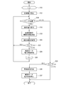
図2は、図1の電力負荷制御システムの制御装置32が実行する制御方法の一例の概略的な手順を示すフローチャートである。
図2の制御方法では、制御装置32は、初期設定としてフラグFを0に設定する(初期設定工程S10)。それから、制御装置32は、外部電力系統24から内部電力系統20に供給される電力、又は、内部電力系統20から外部電力系統24に供給される電力の目標値Ptを読み込む(目標値読込工程S12)。目標値Ptは、予め制御装置32の記憶装置に登録されていてもよいし、作業者が入力してもよい。
図2の制御方法では、制御装置32は、初期設定としてフラグFを0に設定する(初期設定工程S10)。それから、制御装置32は、外部電力系統24から内部電力系統20に供給される電力、又は、内部電力系統20から外部電力系統24に供給される電力の目標値Ptを読み込む(目標値読込工程S12)。目標値Ptは、予め制御装置32の記憶装置に登録されていてもよいし、作業者が入力してもよい。
次に、制御装置32は、送風機18の運転が必要であるか否かを判定する(判定工程S14)。判定工程S14の判定の結果、送風機18の運転が必要である場合(はいの場合)、電力計26が電力を測定し(電力測定工程)、制御装置32が、電力計26によって測定された電力の測定値Pmを取得する(測定値取得工程S16)。
その後、制御装置32は、電力の目標値Ptと測定値Pmに基づいて、蒸気制御弁31の開度の目標値Vtを演算する(蒸気制御弁開度演算工程S18)。そして、制御装置32の蒸気制御弁制御部36は、蒸気制御弁31の開度が目標値Vtに近付くように、蒸気制御弁31を制御する(蒸気制御弁制御工程S20)。
それから、制御装置32は、フラグFが1であるか否かを判定し(フラグ判定工程S22)、フラグ判定工程S22の判定の結果、フラグFが1ではない場合(いいえの場合)、制御装置32のモータ制御部38は、受配電盤22に電動モータ28への電力供給を開始させる(電動モータ電力供給開始工程S24)。そして、制御装置32は、フラグFを1に設定し(フラグ設定工程S26)、フローは判定工程S14に戻る。
この後、送風機18の運転が要求されている限り、測定値取得工程S16、蒸気制御弁開度演算工程S18、蒸気制御弁制御工程S20、及び、フラグ判定工程S22が繰り返される。
この後、送風機18の運転が要求されている限り、測定値取得工程S16、蒸気制御弁開度演算工程S18、蒸気制御弁制御工程S20、及び、フラグ判定工程S22が繰り返される。
一方、判定工程S14において、送風機18の運転が要求されていない場合(いいえの場合)、制御装置32は、フラグFが1であるか否かを判定する(フラグ判定工程S28)。フラグ判定工程S28の判定の結果、フラグFが1である場合(はいの場合)、制御装置32の蒸気制御弁制御部36は蒸気制御弁31を閉じるとともに(蒸気制御弁閉工程S30)、制御装置32のモータ制御部38は、受配電盤22に対し、電動モータ28への電力供給を停止させる(電動モータ電力供給停止工程S32)。以上で制御方法の一連のフローが終了するが、フラグ判定工程S28の判定の結果、フラグFが0である場合(いいえの場合)にも一連のフローが終了する。なお、制御装置32が上述した一連のフローを繰り返し実行することによって、必要に応じて送風機18を作動させることができる。
外部電力系統24から内部電力系統20に供給される電力、又は、内部電力系統20から外部電力系統24に供給される電力は、内部電力系統20に接続された全ての電力負荷の大きさによって変化する。この点、上述した電力負荷管理システム及び制御方法の構成によれば、電力計26によって測定される電力の測定値Pmに基づいて蒸気制御弁31を制御することにより、電動モータ28の電力負荷の大きさを変化させることができ、内部電力系統20に接続された全電力負荷の大きさを調整することができる。従って、この構成によれば、外部電力系統24から内部電力系統20に供給される電力、又は、内部電力系統20から外部電力系統24に供給される電力を安定させることができる。
幾つかの実施形態では、制御装置32は、電力計26によって測定された電力の測定値Pmが予め設定された電力の目標値Ptに近付くように蒸気制御弁31を制御するように構成されている。
この構成によれば、外部電力系統24から内部電力系統20に供給される電力、又は、内部電力系統20から外部電力系統24に供給される電力を、電力の目標値Ptの近傍で安定させることができる。特に、電動モータ28の電力負荷の大きさを調整することにより、内部電力系統20に接続された全電力負荷の大きさを調整する場合、電動モータ28の電力負荷の大きさは速やかに変化する。
この構成によれば、外部電力系統24から内部電力系統20に供給される電力、又は、内部電力系統20から外部電力系統24に供給される電力を、電力の目標値Ptの近傍で安定させることができる。特に、電動モータ28の電力負荷の大きさを調整することにより、内部電力系統20に接続された全電力負荷の大きさを調整する場合、電動モータ28の電力負荷の大きさは速やかに変化する。
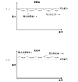
ここで、図3(a)は、買電時に電力計26によって測定される電力の測定値Pmの時間変化を、電力の目標値Pt及び契約電力とともに概略的に示すグラフであり、図3(b)は、売電時に電力計26によって測定される電力の測定値Pmの時間変化を、電力の目標値Pt及び契約電力とともに概略的に示すグラフである。
図3(a)及び(b)に示したように、電動モータ28の電力負荷の大きさが速やかに変化して応答性が良いことで、契約電力又は電力の目標値Ptからの測定値Pmの偏差を小さくすることができる。このため、外部電力系統24から電力を買う場合には、契約電力を低く設定して買電のコストを削減することができる。あるいは、外部電力系統24に対し電力を売る場合には、必要最小限の発電量で契約電力を確保することができ、発電コストを削減することができる。
図3(a)及び(b)に示したように、電動モータ28の電力負荷の大きさが速やかに変化して応答性が良いことで、契約電力又は電力の目標値Ptからの測定値Pmの偏差を小さくすることができる。このため、外部電力系統24から電力を買う場合には、契約電力を低く設定して買電のコストを削減することができる。あるいは、外部電力系統24に対し電力を売る場合には、必要最小限の発電量で契約電力を確保することができ、発電コストを削減することができる。
幾つかの実施形態では、買電時には、電力の目標値Ptは測定値Pmとの偏差を考慮して契約電力よりも小さな値に設定され、売電時には、電力の目標値Ptは測定値Pmとの偏差を考慮して契約電力よりも大きな値に設定される。
幾つかの実施形態では、電動モータ28は誘導電動機である。
幾つかの実施形態では、電動モータ28としての誘導発電機は、蒸気タービン30によって駆動されることによって発電可能に構成されている。この構成によれば、電動モータ28が発電することによって、電力負荷の大きな変動を補償することができる。
幾つかの実施形態では、電動モータ28としての誘導発電機は、蒸気タービン30によって駆動されることによって発電可能に構成されている。この構成によれば、電動モータ28が発電することによって、電力負荷の大きな変動を補償することができる。
幾つかの実施形態では、蒸気タービン30と電動モータ28は、ワンウェイクラッチ40を介して接続され、電動モータ28が送風機18に接続されている。ワンウェイクラッチ40は、蒸気タービン30の回転数が電動モータ28の回転数を上回っているときに、蒸気タービン30と電動モータ28とを連結し、蒸気タービン30の回転数が電動モータ28の回転数以下である場合、蒸気タービン30と電動モータ28とを切り離すように構成されている。
この構成によれば、簡単な構成にて、蒸気タービン30の動力を送風機18に伝達することができる。
この構成によれば、簡単な構成にて、蒸気タービン30の動力を送風機18に伝達することができる。
幾つかの実施形態では、ボイラ12と蒸気制御弁31との間に、蒸気を蓄える蒸気アキュムレータ42が介装されている。
蒸気タービン30に供給すべき蒸気量が増大したときに、ボイラ12での蒸気発生量を増大させるには時間がかかる。この構成によれば、蒸気アキュムレータ42に蒸気を蓄えているので、蒸気タービン30に供給すべき蒸気量が増大したときに、蒸気タービン30に必要な蒸気を速やかに供給することができる。
蒸気タービン30に供給すべき蒸気量が増大したときに、ボイラ12での蒸気発生量を増大させるには時間がかかる。この構成によれば、蒸気アキュムレータ42に蒸気を蓄えているので、蒸気タービン30に供給すべき蒸気量が増大したときに、蒸気タービン30に必要な蒸気を速やかに供給することができる。
本発明は、上述した幾つかの実施形態に限定されることはなく、上述した幾つかの実施形態に変形を加えた形態や、上述した幾つかの実施形態を組み合わせた形態も含む。
例えば、上述した幾つかの実施形態では、産業施設が自家用発電プラント10を有していたけれども、外部電力系統24から電力を買うのみであれば、タービン14及び発電機16は必要ではなく、産業施設はボイラ12を有していればよい。
例えば、上述した幾つかの実施形態では、産業施設が自家用発電プラント10を有していたけれども、外部電力系統24から電力を買うのみであれば、タービン14及び発電機16は必要ではなく、産業施設はボイラ12を有していればよい。
また例えば、上述した幾つかの実施形態では、産業施設に1つの電動モータ28が設けられていたが、複数の電動モータ28が設けられていてもよい。この場合、制御装置32は、複数の電動モータ28に供給される電力を調整するように構成されていてもよい。また、制御装置32は、複数の電動モータ28に対応して、複数の蒸気タービン30に供給される蒸気量を調整するように構成された複数の蒸気制御弁31を制御するように構成されていてもよい。
10 自家用発電プラント
12 ボイラ
14 タービン
16 発電機
18 送風機
20 内部電力系統
22 受配電盤
24 外部電力系統
26 電力計
28 電動モータ
30 蒸気タービン
31 蒸気制御弁
32 制御装置
34 動力線
35 配管
36 蒸気制御弁制御部
38 モータ制御部
39 主蒸気制御弁
40 ワンウェイクラッチ
42 蒸気アキュムレータ
12 ボイラ
14 タービン
16 発電機
18 送風機
20 内部電力系統
22 受配電盤
24 外部電力系統
26 電力計
28 電動モータ
30 蒸気タービン
31 蒸気制御弁
32 制御装置
34 動力線
35 配管
36 蒸気制御弁制御部
38 モータ制御部
39 主蒸気制御弁
40 ワンウェイクラッチ
42 蒸気アキュムレータ
Claims (4)
- 外部電力系統から内部電力系統に供給される電力又は前記内部電力系統から前記外部電力系統に供給される電力を測定するように構成された電力計と、
少なくとも1つの送風機と、
前記少なくとも1つの送風機に連結され、前記内部電力系統から受け取った電力によって前記少なくとも1つの送風機を駆動するように構成された電動モータと、
供給された蒸気によって前記少なくとも1つの送風機を駆動するように構成された蒸気タービンと、
前記蒸気タービンへの蒸気の供給量を調整可能に構成された蒸気制御弁と、
前記電力計によって測定された電力の測定値に基づいて、前記蒸気制御弁を制御するように構成された制御装置と
を備えることを特徴とする電力負荷管理システム。 - 前記制御装置は、前記電力計によって測定された電力の測定値が予め設定された電力の目標値に近付くように前記蒸気制御弁を制御するように構成されている
ことを特徴とする請求項1に記載の電力負荷管理システム。 - 前記電動モータは、前記蒸気タービンによって駆動されることによって発電可能に構成されている
ことを特徴とする請求項1又は2に記載の電力負荷管理システム。 - 少なくとも1つの送風機と、
前記少なくとも1つの送風機に連結され、内部電力系統から受け取った電力によって前記少なくとも1つの送風機を駆動するように構成された電動モータと、
供給された蒸気によって前記少なくとも1つの送風機を駆動するように構成された蒸気タービンと、
前記蒸気タービンへの蒸気の供給量を調整可能に構成された蒸気制御弁と
を備える電力負荷管理システムの制御方法において、
外部電力系統から前記内部電力系統に供給される電力又は前記内部電力系統から外部電力系統に供給される電力を測定する電力測定工程と、
前記電力測定工程によって測定された電力の測定値に基づいて、前記蒸気制御弁を制御する蒸気制御弁制御工程と
を備えることを特徴とする電力負荷管理システムの制御方法。
Applications Claiming Priority (2)
| Application Number | Priority Date | Filing Date | Title |
|---|---|---|---|
| JP2014-139903 | 2014-07-07 | ||
| JP2014139903A JP6283274B2 (ja) | 2014-07-07 | 2014-07-07 | 電力負荷管理システム及びその制御方法及び産業施設 |
Publications (1)
| Publication Number | Publication Date |
|---|---|
| WO2016006360A1 true WO2016006360A1 (ja) | 2016-01-14 |
Family
ID=55064002
Family Applications (1)
| Application Number | Title | Priority Date | Filing Date |
|---|---|---|---|
| PCT/JP2015/065545 Ceased WO2016006360A1 (ja) | 2014-07-07 | 2015-05-29 | 電力負荷管理システム及びその制御方法 |
Country Status (2)
| Country | Link |
|---|---|
| JP (1) | JP6283274B2 (ja) |
| WO (1) | WO2016006360A1 (ja) |
Citations (4)
| Publication number | Priority date | Publication date | Assignee | Title |
|---|---|---|---|---|
| JPS60164604A (ja) * | 1984-02-08 | 1985-08-27 | Hitachi Ltd | 買電量制御方法 |
| JPS60258404A (ja) * | 1984-06-05 | 1985-12-20 | Kawasaki Steel Corp | 高炉送風装置 |
| JPH0476200U (ja) * | 1990-11-15 | 1992-07-02 | ||
| JPH11264006A (ja) * | 1998-03-16 | 1999-09-28 | Kawasaki Steel Corp | 蒸気タービン及び電動モータ併設送風設備の制御方法 |
-
2014
- 2014-07-07 JP JP2014139903A patent/JP6283274B2/ja active Active
-
2015
- 2015-05-29 WO PCT/JP2015/065545 patent/WO2016006360A1/ja not_active Ceased
Patent Citations (4)
| Publication number | Priority date | Publication date | Assignee | Title |
|---|---|---|---|---|
| JPS60164604A (ja) * | 1984-02-08 | 1985-08-27 | Hitachi Ltd | 買電量制御方法 |
| JPS60258404A (ja) * | 1984-06-05 | 1985-12-20 | Kawasaki Steel Corp | 高炉送風装置 |
| JPH0476200U (ja) * | 1990-11-15 | 1992-07-02 | ||
| JPH11264006A (ja) * | 1998-03-16 | 1999-09-28 | Kawasaki Steel Corp | 蒸気タービン及び電動モータ併設送風設備の制御方法 |
Also Published As
| Publication number | Publication date |
|---|---|
| JP2016017443A (ja) | 2016-02-01 |
| JP6283274B2 (ja) | 2018-02-21 |
Similar Documents
| Publication | Publication Date | Title |
|---|---|---|
| US9163828B2 (en) | Model-based load demand control | |
| JP6046890B2 (ja) | 蒸気タービンの装荷方法及び装荷システム | |
| CA2868093C (en) | Steam temperature control using model-based temperature balancing | |
| CA2914954C (en) | Model-based combined cycle power plant load control | |
| PH12010000273A1 (en) | Optimized control of power plants having air cooled condensers | |
| JP2015090132A5 (ja) | ||
| EP2792858B1 (en) | Steam turbine power plant | |
| CN104612762B (zh) | 蒸汽轮机发电装置及其启动方法 | |
| CN102374518A (zh) | 使用动态矩阵控制的蒸汽温度控制 | |
| JP2015090091A5 (ja) | ||
| JP2014142176A (ja) | 給水ポンプ再循環弁のためにオーバライド制御を提供するためのシステムおよび方法 | |
| CN105899874A (zh) | 用于发电和/或供热的蒸汽发生器的功率调节的方法 | |
| JP5343935B2 (ja) | ボイラシステム | |
| JP6283274B2 (ja) | 電力負荷管理システム及びその制御方法及び産業施設 | |
| KR20200030504A (ko) | 연료 삭감율 출력 시스템, 연료 삭감율 출력 방법 및 연료 삭감율 출력 프로그램 | |
| JP6510923B2 (ja) | 発電プラントの起動制御装置及び起動制御方法 | |
| Annus et al. | Pumps energy consumption based on new EU legislation | |
| JP5544314B2 (ja) | 用役設備の最適運転システム | |
| JP2013234847A (ja) | ボイラシステム | |
| JP2014177874A (ja) | 自家発電設備の制御装置および制御方法 | |
| JP6668420B2 (ja) | 送電電力量制御装置および分散型発電設備 | |
| JP6365553B2 (ja) | 電力調整方法 | |
| JP2017028764A (ja) | 需要電力制御装置および需要電力制御方法 | |
| KR20160058451A (ko) | 선박용 이종 열교환 시스템 및 이를 사용한 이종 열교환 방법 | |
| RU2013157365A (ru) | Система управления для многовариантного регулирования теплоэлектростанции |
Legal Events
| Date | Code | Title | Description |
|---|---|---|---|
| 121 | Ep: the epo has been informed by wipo that ep was designated in this application |
Ref document number: 15818472 Country of ref document: EP Kind code of ref document: A1 |
|
| NENP | Non-entry into the national phase |
Ref country code: DE |
|
| 122 | Ep: pct application non-entry in european phase |
Ref document number: 15818472 Country of ref document: EP Kind code of ref document: A1 |