WO2016006331A1 - Nickel-zinc battery - Google Patents
Nickel-zinc battery Download PDFInfo
- Publication number
- WO2016006331A1 WO2016006331A1 PCT/JP2015/064616 JP2015064616W WO2016006331A1 WO 2016006331 A1 WO2016006331 A1 WO 2016006331A1 JP 2015064616 W JP2015064616 W JP 2015064616W WO 2016006331 A1 WO2016006331 A1 WO 2016006331A1
- Authority
- WO
- WIPO (PCT)
- Prior art keywords
- negative electrode
- positive electrode
- nickel
- separator
- zinc battery
- Prior art date
Links
Images

Classifications
-
- H—ELECTRICITY
- H01—ELECTRIC ELEMENTS
- H01M—PROCESSES OR MEANS, e.g. BATTERIES, FOR THE DIRECT CONVERSION OF CHEMICAL ENERGY INTO ELECTRICAL ENERGY
- H01M10/00—Secondary cells; Manufacture thereof
- H01M10/24—Alkaline accumulators
- H01M10/30—Nickel accumulators
-
- H—ELECTRICITY
- H01—ELECTRIC ELEMENTS
- H01M—PROCESSES OR MEANS, e.g. BATTERIES, FOR THE DIRECT CONVERSION OF CHEMICAL ENERGY INTO ELECTRICAL ENERGY
- H01M10/00—Secondary cells; Manufacture thereof
- H01M10/24—Alkaline accumulators
- H01M10/28—Construction or manufacture
-
- H—ELECTRICITY
- H01—ELECTRIC ELEMENTS
- H01M—PROCESSES OR MEANS, e.g. BATTERIES, FOR THE DIRECT CONVERSION OF CHEMICAL ENERGY INTO ELECTRICAL ENERGY
- H01M10/00—Secondary cells; Manufacture thereof
- H01M10/34—Gastight accumulators
-
- H—ELECTRICITY
- H01—ELECTRIC ELEMENTS
- H01M—PROCESSES OR MEANS, e.g. BATTERIES, FOR THE DIRECT CONVERSION OF CHEMICAL ENERGY INTO ELECTRICAL ENERGY
- H01M4/00—Electrodes
- H01M4/02—Electrodes composed of, or comprising, active material
- H01M4/36—Selection of substances as active materials, active masses, active liquids
- H01M4/38—Selection of substances as active materials, active masses, active liquids of elements or alloys
-
- H—ELECTRICITY
- H01—ELECTRIC ELEMENTS
- H01M—PROCESSES OR MEANS, e.g. BATTERIES, FOR THE DIRECT CONVERSION OF CHEMICAL ENERGY INTO ELECTRICAL ENERGY
- H01M4/00—Electrodes
- H01M4/02—Electrodes composed of, or comprising, active material
- H01M4/36—Selection of substances as active materials, active masses, active liquids
- H01M4/48—Selection of substances as active materials, active masses, active liquids of inorganic oxides or hydroxides
- H01M4/52—Selection of substances as active materials, active masses, active liquids of inorganic oxides or hydroxides of nickel, cobalt or iron
-
- H—ELECTRICITY
- H01—ELECTRIC ELEMENTS
- H01M—PROCESSES OR MEANS, e.g. BATTERIES, FOR THE DIRECT CONVERSION OF CHEMICAL ENERGY INTO ELECTRICAL ENERGY
- H01M50/00—Constructional details or processes of manufacture of the non-active parts of electrochemical cells other than fuel cells, e.g. hybrid cells
- H01M50/40—Separators; Membranes; Diaphragms; Spacing elements inside cells
- H01M50/409—Separators, membranes or diaphragms characterised by the material
- H01M50/431—Inorganic material
- H01M50/434—Ceramics
-
- H—ELECTRICITY
- H01—ELECTRIC ELEMENTS
- H01M—PROCESSES OR MEANS, e.g. BATTERIES, FOR THE DIRECT CONVERSION OF CHEMICAL ENERGY INTO ELECTRICAL ENERGY
- H01M50/00—Constructional details or processes of manufacture of the non-active parts of electrochemical cells other than fuel cells, e.g. hybrid cells
- H01M50/40—Separators; Membranes; Diaphragms; Spacing elements inside cells
- H01M50/409—Separators, membranes or diaphragms characterised by the material
- H01M50/443—Particulate material
-
- H—ELECTRICITY
- H01—ELECTRIC ELEMENTS
- H01M—PROCESSES OR MEANS, e.g. BATTERIES, FOR THE DIRECT CONVERSION OF CHEMICAL ENERGY INTO ELECTRICAL ENERGY
- H01M50/00—Constructional details or processes of manufacture of the non-active parts of electrochemical cells other than fuel cells, e.g. hybrid cells
- H01M50/40—Separators; Membranes; Diaphragms; Spacing elements inside cells
- H01M50/409—Separators, membranes or diaphragms characterised by the material
- H01M50/449—Separators, membranes or diaphragms characterised by the material having a layered structure
-
- H—ELECTRICITY
- H01—ELECTRIC ELEMENTS
- H01M—PROCESSES OR MEANS, e.g. BATTERIES, FOR THE DIRECT CONVERSION OF CHEMICAL ENERGY INTO ELECTRICAL ENERGY
- H01M50/00—Constructional details or processes of manufacture of the non-active parts of electrochemical cells other than fuel cells, e.g. hybrid cells
- H01M50/40—Separators; Membranes; Diaphragms; Spacing elements inside cells
- H01M50/463—Separators, membranes or diaphragms characterised by their shape
-
- H—ELECTRICITY
- H01—ELECTRIC ELEMENTS
- H01M—PROCESSES OR MEANS, e.g. BATTERIES, FOR THE DIRECT CONVERSION OF CHEMICAL ENERGY INTO ELECTRICAL ENERGY
- H01M50/00—Constructional details or processes of manufacture of the non-active parts of electrochemical cells other than fuel cells, e.g. hybrid cells
- H01M50/40—Separators; Membranes; Diaphragms; Spacing elements inside cells
- H01M50/489—Separators, membranes, diaphragms or spacing elements inside the cells, characterised by their physical properties, e.g. swelling degree, hydrophilicity or shut down properties
- H01M50/497—Ionic conductivity
-
- H—ELECTRICITY
- H01—ELECTRIC ELEMENTS
- H01M—PROCESSES OR MEANS, e.g. BATTERIES, FOR THE DIRECT CONVERSION OF CHEMICAL ENERGY INTO ELECTRICAL ENERGY
- H01M2300/00—Electrolytes
- H01M2300/0002—Aqueous electrolytes
- H01M2300/0014—Alkaline electrolytes
-
- H—ELECTRICITY
- H01—ELECTRIC ELEMENTS
- H01M—PROCESSES OR MEANS, e.g. BATTERIES, FOR THE DIRECT CONVERSION OF CHEMICAL ENERGY INTO ELECTRICAL ENERGY
- H01M2300/00—Electrolytes
- H01M2300/0017—Non-aqueous electrolytes
- H01M2300/0065—Solid electrolytes
- H01M2300/0068—Solid electrolytes inorganic
-
- H—ELECTRICITY
- H01—ELECTRIC ELEMENTS
- H01M—PROCESSES OR MEANS, e.g. BATTERIES, FOR THE DIRECT CONVERSION OF CHEMICAL ENERGY INTO ELECTRICAL ENERGY
- H01M4/00—Electrodes
- H01M4/02—Electrodes composed of, or comprising, active material
- H01M4/36—Selection of substances as active materials, active masses, active liquids
- H01M4/38—Selection of substances as active materials, active masses, active liquids of elements or alloys
- H01M4/42—Alloys based on zinc
-
- H—ELECTRICITY
- H01—ELECTRIC ELEMENTS
- H01M—PROCESSES OR MEANS, e.g. BATTERIES, FOR THE DIRECT CONVERSION OF CHEMICAL ENERGY INTO ELECTRICAL ENERGY
- H01M50/00—Constructional details or processes of manufacture of the non-active parts of electrochemical cells other than fuel cells, e.g. hybrid cells
- H01M50/40—Separators; Membranes; Diaphragms; Spacing elements inside cells
- H01M50/409—Separators, membranes or diaphragms characterised by the material
- H01M50/446—Composite material consisting of a mixture of organic and inorganic materials
-
- Y—GENERAL TAGGING OF NEW TECHNOLOGICAL DEVELOPMENTS; GENERAL TAGGING OF CROSS-SECTIONAL TECHNOLOGIES SPANNING OVER SEVERAL SECTIONS OF THE IPC; TECHNICAL SUBJECTS COVERED BY FORMER USPC CROSS-REFERENCE ART COLLECTIONS [XRACs] AND DIGESTS
- Y02—TECHNOLOGIES OR APPLICATIONS FOR MITIGATION OR ADAPTATION AGAINST CLIMATE CHANGE
- Y02E—REDUCTION OF GREENHOUSE GAS [GHG] EMISSIONS, RELATED TO ENERGY GENERATION, TRANSMISSION OR DISTRIBUTION
- Y02E60/00—Enabling technologies; Technologies with a potential or indirect contribution to GHG emissions mitigation
- Y02E60/10—Energy storage using batteries
-
- Y—GENERAL TAGGING OF NEW TECHNOLOGICAL DEVELOPMENTS; GENERAL TAGGING OF CROSS-SECTIONAL TECHNOLOGIES SPANNING OVER SEVERAL SECTIONS OF THE IPC; TECHNICAL SUBJECTS COVERED BY FORMER USPC CROSS-REFERENCE ART COLLECTIONS [XRACs] AND DIGESTS
- Y02—TECHNOLOGIES OR APPLICATIONS FOR MITIGATION OR ADAPTATION AGAINST CLIMATE CHANGE
- Y02P—CLIMATE CHANGE MITIGATION TECHNOLOGIES IN THE PRODUCTION OR PROCESSING OF GOODS
- Y02P70/00—Climate change mitigation technologies in the production process for final industrial or consumer products
- Y02P70/50—Manufacturing or production processes characterised by the final manufactured product
Definitions
- the present invention relates to a nickel zinc battery.
- Nickel-zinc secondary batteries have been developed and studied for a long time, but have not yet been put into practical use. This is because the zinc constituting the negative electrode produces dendritic crystals called dendrite during charging, and this dendrite breaks through the separator and causes a short circuit with the positive electrode.
- nickel cadmium batteries and nickel metal hydride batteries have already been commercialized.
- the nickel-zinc secondary battery has an extremely high theoretical capacity density of about 5 times that of the nickel-cadmium secondary battery, 2.5 times that of the nickel-hydrogen secondary battery, and 1.3 times that of the lithium-ion battery. And the raw material price is low. Therefore, a technique for preventing a short circuit due to zinc dendrite in a nickel zinc secondary battery is strongly desired.
- Patent Document 1 International Publication No. 2013/118561
- a separator made of a hydroxide ion conductive inorganic solid electrolyte is provided between a positive electrode and a negative electrode for the purpose of preventing a short circuit due to zinc dendrite.
- Nickel zinc secondary batteries have been proposed.
- the inorganic solid electrolyte body has a relative density of 90% or more, the general formula: M 2+ 1-x M 3+ x (OH) in 2 A n- x / n ⁇ mH 2 O (wherein, M 2+ is at least 1 a kind or more divalent cations, M 3+ is at least one or more trivalent cations, a n-is the n-valent anion, n represents an integer of 1 or more, x is 0. It is disclosed in this document that it can consist of layered double hydroxides having a basic composition of 1 to 0.4.
- Patent Document 2 Japanese Patent Application Laid-Open No. 5-303978 discloses a hermetic seal having an electrode plate group having a positive electrode plate, a negative electrode plate, a separator, and a retainer, and a liquid retaining layer disposed around the electrode plate group.
- a nickel-zinc battery is disclosed, and it is disclosed that the liquid retaining layer contains an electrolytic solution in cellulose fibers having a length of 0.5 to 50 mm and a diameter of 5 to 100 ⁇ m.
- a separator obtained by treating a porous polypropylene membrane with a surfactant is used.
- Patent Document 3 Japanese Patent Laid-Open No. 6-96795
- the electrode plate surface of the electrode group is disposed so as to face the bottom surface of the battery case, and the volume of the electrolyte exceeds 110% of the total space volume of the electrode group. %, But a microporous film and a cellophane film are used as a separator.
- Patent Document 4 Japanese Patent Application Laid-Open No. 5-36394 discloses an alkaline battery separator made of a hydrophobic resin porous membrane having at least hydrophilic fibers on the surface.
- the present inventors have now obtained the knowledge that a highly reliable nickel-zinc battery can be provided by using a separator having hydroxide ion conductivity but not water permeability.
- an object of the present invention is to provide a highly reliable nickel-zinc battery using a separator having hydroxide ion conductivity but not water permeability.
- a positive electrode comprising nickel hydroxide and / or nickel oxyhydroxide
- a positive electrode electrolyte solution comprising an alkali metal hydroxide, in which the positive electrode is immersed
- a negative electrode comprising zinc and / or zinc oxide
- a negative electrode electrolyte solution comprising an alkali metal hydroxide, in which the negative electrode is immersed
- a sealed container containing the positive electrode, the positive electrode electrolyte, the negative electrode, and the negative electrode electrolyte; In the sealed container, provided to partition the positive electrode chamber containing the positive electrode and the positive electrode electrolyte solution and the negative electrode chamber containing the negative electrode and the negative electrode electrolyte solution, and has hydroxide ion conductivity.
- a separator having no water permeability;
- a nickel zinc battery comprising:
- FIG. 1 It is a conceptual diagram which shows typically an example of the nickel zinc battery by this invention, and shows a discharge end state. It is a figure which shows the full charge state of the nickel zinc battery shown by FIG. It is a conceptual diagram which shows typically an example of the parallel lamination type nickel zinc battery by this invention, and shows the end-of-discharge state. It is a schematic cross section showing one mode of a separator with a porous substrate. It is a schematic cross section which shows the other one aspect
- FIG. 3 is an XRD profile obtained for the crystal phase of the sample in Example 1.
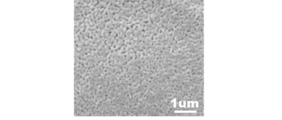
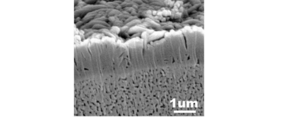
- 2 is an SEM image showing a surface microstructure of a film sample observed in Example 1.
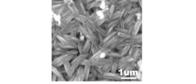
- 2 is an SEM image of a polished cross-sectional microstructure of a composite material sample observed in Example 1.
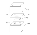
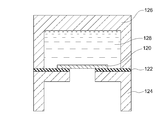
- FIG. 2 is an exploded perspective view of a denseness discrimination measurement system used in Example 1.
- FIG. 2 is a schematic cross-sectional view of a denseness discrimination measurement system used in Example 1.
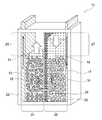
- FIG. 1 schematically shows an example of a nickel zinc battery according to the present invention.
- the nickel zinc battery shown in FIG. 1 shows an initial state before charging, and corresponds to a discharged state.
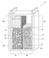
- the nickel-zinc battery of the present invention may be configured in a fully charged state.
- a nickel zinc battery 10 according to the present invention includes a positive electrode 12, a positive electrode electrolyte 14, a negative electrode 16, a negative electrode electrolyte 18, and a separator 20 in a sealed container 22.
- the positive electrode 12 includes nickel hydroxide and / or nickel oxyhydroxide.
- the positive electrode electrolyte 14 contains an alkali metal hydroxide, and the positive electrode 12 is immersed therein.
- the negative electrode 16 includes zinc and / or zinc oxide.
- the negative electrode electrolyte 18 contains an alkali metal hydroxide, and the negative electrode 16 is immersed therein.
- the sealed container 22 contains the positive electrode 12, the positive electrode electrolyte 14, the negative electrode 16, and the negative electrode electrolyte 18.
- the positive electrode 12 and the positive electrode electrolyte solution 14 are not necessarily separated from each other, and may be configured as a positive electrode mixture in which the positive electrode 12 and the positive electrode electrolyte solution 14 are mixed.
- the negative electrode 16 and the negative electrode electrolyte 18 are not necessarily separated from each other, and may be configured as a negative electrode mixture in which the negative electrode 16 and the negative electrode electrolyte 18 are mixed.
- a positive electrode current collector 13 is provided in contact with the positive electrode 12.
- a negative electrode current collector 17 is provided in contact with the negative electrode 16.
- the separator 20 is provided in the sealed container 22 so as to partition a positive electrode chamber 24 that accommodates the positive electrode 12 and the positive electrode electrolyte solution 14 and a negative electrode chamber 26 that accommodates the negative electrode 16 and the negative electrode electrolyte solution 18.
- the separator 20 has hydroxide ion conductivity but does not have water permeability.
- “not having water permeability” means “measurement object (when the water permeability is evaluated by a“ denseness determination test ”employed in Example 1 described later) or a technique or configuration according thereto. For example, it means that water that contacts one side of the separator 20 and / or the porous substrate 28) does not permeate the other side.
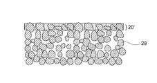
- the separator 20 does not have water permeability means that the separator 20 has a high degree of denseness that does not allow water to pass through, and is not a porous film or other porous material having water permeability. Means. For this reason, it has a very effective configuration for physically preventing penetration of the separator by zinc dendrite generated during charging and preventing a short circuit between the positive and negative electrodes.
- the porous substrate 28 may be attached to the separator 20 as shown in FIG. In any case, since the separator 20 has hydroxide ion conductivity, it is possible to efficiently move the required hydroxide ions between the positive electrode electrolyte 14 and the negative electrode electrolyte 18, and the positive electrode chamber 24 and the negative electrode.
- the charge / discharge reaction in the chamber 26 can be realized.
- the reaction at the time of charging in the positive electrode chamber 24 and the negative electrode chamber 26 is as shown below, and the discharge reaction is reversed.
- the negative electrode reaction is composed of the following two reactions.
- -ZnO dissolution reaction ZnO + H 2 O + 2OH ⁇ ⁇ Zn (OH) 4 2 ⁇ - precipitation reaction of Zn: Zn (OH) 4 2- + 2e - ⁇ Zn + 4OH -
- the nickel zinc battery 10 has a positive electrode-side surplus space 25 having a volume that allows an increase / decrease in the amount of water accompanying the positive electrode reaction during charge / discharge in the positive electrode chamber 24, and accompanies the negative electrode reaction during charge / discharge in the negative electrode chamber 26. It is preferable to have a negative electrode-side surplus space 27 having a volume that allows a decrease in the amount of moisture. This effectively prevents problems associated with the increase or decrease in the amount of moisture in the positive electrode chamber 24 and the negative electrode chamber 26 (for example, liquid leakage, deformation of the container due to changes in the container internal pressure, etc.), and further improves the reliability of the nickel zinc battery. Can be improved.
- the positive electrode chamber 24 has a positive electrode-side surplus space 25 having a volume that allows an increase or decrease in the amount of water associated with the positive electrode reaction during charge / discharge, thereby increasing the positive electrolyte 14 during charging as shown in FIG. It can be made to function as a buffer that can cope with this. That is, as shown in FIG. 2, the positive electrode side excess space 25 functions as a buffer even after full charge, so that the increased amount of the positive electrode electrolyte solution 14 is reliably held in the positive electrode chamber 24 without overflowing. Can do.
- the negative electrode chamber 26 has a negative electrode-side surplus space 27 having a volume that allows a decrease in the amount of water associated with the negative electrode reaction during charge / discharge, thereby functioning as a buffer that can cope with an increase in the negative electrode electrolyte 18 during discharge. Can be made.
- moisture content in the positive electrode chamber 24 and the negative electrode chamber 26 can be calculated based on the reaction formula mentioned above.
- the amount of H 2 O produced at the positive electrode 12 during charging corresponds to twice the amount of H 2 O consumed at the negative electrode 16. Therefore, the volume of the positive electrode side surplus space 25 may be larger than that of the negative electrode side surplus space 27.
- the volume of the positive-side surplus space 25 can be generated not only from the amount of water increase expected in the positive electrode chamber 24 but also from the positive electrode 12 during overcharge or a gas such as air existing in the positive electrode chamber 24 in advance. It is preferable that the volume has a slight or some margin so that oxygen gas can be accommodated at an appropriate internal pressure.
- the negative side surplus space 27 has the same volume as the positive side surplus space 25 as shown in FIG. It is desirable to provide a surplus space that exceeds the amount of water reduction. In any case, the negative electrode side surplus space 27 may be smaller than the positive electrode side surplus space 25 because the amount of water increases or decreases by about half of the amount in the positive electrode chamber 24.
- the positive-side surplus space 25 has a volume that exceeds the amount of water expected to increase with the positive-electrode reaction during charging, and the positive-side surplus space 25 Is not filled with the positive electrode electrolyte 14 in advance, and the negative electrode side surplus space 27 has a volume exceeding the amount of water expected to decrease with the negative electrode reaction during charging, and the negative electrode side surplus space 27 Is preferably filled in advance with an amount of the negative electrode electrolyte 18 that is expected to decrease.
- the positive-side surplus space 25 has a volume exceeding the amount of water expected to decrease with the positive-electrode reaction during discharge, and the positive-side surplus The space 25 is preliminarily filled with an amount of the positive electrode electrolyte 14 that is expected to decrease, and the negative surplus space 27 exceeds the amount of water that is expected to increase with the negative electrode reaction during discharge. It is preferable that the negative electrode side excess space 27 is not filled with the negative electrode electrolyte 18 in advance.
- the positive electrode side surplus space 25 is not filled with the positive electrode 12 and / or the negative electrode side surplus space 27 is not filled with the negative electrode 16, and the positive electrode side surplus space 25 and the negative electrode side surplus space 27 are filled with the positive electrode 12. More preferably, the negative electrode 16 and the negative electrode 16 are not filled. In these surplus spaces, electrolyte can be depleted due to a decrease in the amount of water during charging and discharging. That is, even if these surplus spaces are filled with the positive electrode 12 and the negative electrode 16, they cannot be sufficiently involved in the charge / discharge reaction, which is inefficient. Therefore, the positive electrode 12 and the negative electrode 16 can be more efficiently and stably involved in the battery reaction without waste by not filling the positive electrode 12 and the negative electrode 16 in the positive electrode side excess space 25 and the negative electrode side excess space 27, respectively.
- the nickel zinc battery of the present invention is preferably configured in a vertical structure in which separators are provided vertically.
- the positive electrode chamber / separator / negative electrode chamber are arranged in the horizontal direction (horizontal direction).
- the separator 20 is provided vertically as shown in FIG. 1, it is typical that the positive electrode chamber 24 has a positive side excess space 25 above it, and the negative electrode chamber 26 has a negative side excess space 27 above it. It is.
- the electrolyte solution can be held in the charge / discharge reaction portion of the positive electrode chamber 24 and / or the negative electrode chamber 26 despite the decrease in the electrolyte solution.
- the nickel zinc battery of the present invention may be configured in a horizontal structure in which a separator is provided horizontally.
- the separator is provided horizontally
- the positive electrode chamber / separator / negative electrode chamber is stacked in the vertical direction (vertical direction).
- a gel electrolyte by using a gel electrolyte, the contact between the separator and the electrolyte can be constantly maintained regardless of the decrease in the electrolyte.
- a second separator made of a water-absorbing resin such as a nonwoven fabric or a liquid-retaining resin is disposed between the positive electrode and the separator and / or between the negative electrode and the separator, and the electrolytic solution decreases.
- the electrolytic solution may be held in the charge / discharge reaction part of the positive electrode and / or the negative electrode.
- the water absorbent resin or the liquid retaining resin include polyolefin resins.
- the separator separator 20 is a member having hydroxide ion conductivity but not water permeability, and typically has a plate shape, a film shape, or a layer shape.
- the separator 20 is provided in the sealed container 22, and partitions the positive electrode chamber 24 that stores the positive electrode 12 and the positive electrode electrolyte 14, and the negative electrode chamber 26 that stores the negative electrode 16 and the negative electrode electrolyte 18.
- the separator 20 is preferably made of an inorganic solid electrolyte.
- an inorganic solid electrolyte By using a hydroxide ion conductive inorganic solid electrolyte as the separator 20, the electrolyte solution between the positive and negative electrodes is isolated and the hydroxide ion conductivity is ensured.
- the inorganic solid electrolyte which comprises the separator 20 is typically a dense and hard inorganic solid, the penetration of the separator by the zinc dendrite produced
- the inorganic solid electrolyte body preferably has a relative density of 90% or more, more preferably 92% or more, and even more preferably 95% or more, calculated by the Archimedes method, but prevents penetration of zinc dendrite. It is not limited to this as long as it is as dense and hard as possible.
- a dense and hard inorganic solid electrolyte body can be produced through a hydrothermal treatment. Therefore, a simple green compact that has not been subjected to hydrothermal treatment is not preferable as the inorganic solid electrolyte body of the present invention because it is not dense and is brittle in solution.
- any manufacturing method can be used as long as a dense and hard inorganic solid electrolyte body can be obtained, even if it has not undergone hydrothermal treatment.
- the separator 20 or the inorganic solid electrolyte body may be a composite of a particle group including an inorganic solid electrolyte having hydroxide ion conductivity and an auxiliary component that assists densification and hardening of the particle group.
- the separator 20 includes an open-pore porous body as a base material and an inorganic solid electrolyte (for example, layered double hydroxide) deposited and grown in the pores so as to fill the pores of the porous body. It may be a complex.
- the substance constituting the porous body include ceramics such as alumina and zirconia, and insulating substances such as a porous sheet made of a foamed resin or a fibrous substance.
- the inorganic solid electrolyte has a general formula: M 2+ 1-x M 3+ x (OH) 2 A n ⁇ x / n ⁇ mH 2 O (wherein M 2+ is a divalent cation and M 3+ is 3 the valence of the cation, a n-is the n-valent anion, n is an integer of 1 or more, x is 0.1 to 0.4, the basic of m is any real number) It preferably comprises a layered double hydroxide (LDH) having a composition, more preferably such LDH.
- LDH layered double hydroxide
- M 2+ may be any divalent cation, and preferred examples include Mg 2+ , Ca 2+ and Zn 2+ , and more preferably Mg 2+ .
- M 3+ may be any trivalent cation, but preferred examples include Al 3+ or Cr 3+ , and more preferred is Al 3+ .
- a n- can be any anion, but preferred examples include OH - and CO 3 2- . Therefore, in the general formula, M 2+ comprises Mg 2+, M 3+ comprises Al 3+, A n-is OH - and / or CO preferably contains 3 2-.
- n is an integer of 1 or more, preferably 1 or 2.
- x is 0.1 to 0.4, preferably 0.2 to 0.35.
- m is an arbitrary real number.
- m is a real number or an integer of 0 or more, typically more than 0 or 1 or more. It is also possible to replace the part or all of the M 3+ in the general formula tetravalent or higher valency cation, in which case, the anion A n- coefficients x / n of the above general formula It may be changed as appropriate.
- the inorganic solid electrolyte body is densified by hydrothermal treatment.
- Hydrothermal treatment is extremely effective for the densification of layered double hydroxides, especially Mg—Al type layered double hydroxides.
- Densification by hydrothermal treatment is performed, for example, as described in Patent Document 1 (International Publication No. 2013/118561), in which pure water and a plate-shaped green compact are placed in a pressure vessel, and 120 to 250 ° C., preferably The reaction can be carried out at a temperature of 180 to 250 ° C., 2 to 24 hours, preferably 3 to 10 hours.
- Patent Document 1 International Publication No. 2013/118561
- the reaction can be carried out at a temperature of 180 to 250 ° C., 2 to 24 hours, preferably 3 to 10 hours.
- a more preferable production method using hydrothermal treatment will be described later.
- the inorganic solid electrolyte body may be in the form of a plate, a film, or a layer.
- the film or layer of the inorganic solid electrolyte is on the porous substrate or its It is preferably formed in the inside.
- the plate-like form is used, sufficient hardness can be secured and penetration of zinc dendrites can be more effectively prevented.
- the film or layer form is thinner than the plate, there is an advantage that the resistance of the separator can be significantly reduced while ensuring the minimum necessary hardness to prevent the penetration of zinc dendrite. is there.
- the preferred thickness of the plate-like inorganic solid electrolyte body is 0.01 to 0.5 mm, more preferably 0.02 to 0.2 mm, and still more preferably 0.05 to 0.1 mm. Further, the higher the hydroxide ion conductivity of the inorganic solid electrolyte body is, the higher is desirable, but typically it has a conductivity of 10 ⁇ 4 to 10 ⁇ 1 S / m. On the other hand, in the case of a film-like or layered form, the thickness is preferably 100 ⁇ m or less, more preferably 75 ⁇ m or less, still more preferably 50 ⁇ m or less, particularly preferably 25 ⁇ m or less, and most preferably 5 ⁇ m or less.
- the resistance of the separator 20 can be reduced by being thin.
- the lower limit of the thickness is not particularly limited because it varies depending on the application, but in order to ensure a certain degree of rigidity desired as a separator film or layer, the thickness is preferably 1 ⁇ m or more, more preferably 2 ⁇ m or more. is there.
- the porous substrate 28 may be provided on one side or both sides of the separator 20.
- the porous substrate 28 may be provided on the surface of the separator 20 on the negative electrode 16 side or on the surface of the separator 20 on the positive electrode 12 side.
- the porous base material 28 has water permeability, and therefore, the positive electrode electrolyte 14 and the negative electrode electrolyte 18 can reach the separator 20. It is also possible to hold hydroxide ions more stably.
- the separator 20 can be made thin to reduce the resistance.
- a dense film or a dense layer of an inorganic solid electrolyte (preferably LDH) can be formed on or in the porous substrate 28.
- an inorganic solid electrolyte preferably LDH
- a method of preparing a porous substrate and depositing an inorganic solid electrolyte on the porous substrate can be considered (this method will be described later).
- a porous base material on both surfaces of the separator 20 it can be considered that the raw material powder of the inorganic solid electrolyte is sandwiched between two porous base materials for densification.
- the porous substrate 28 is provided over the entire surface of one side of the separator 20, but may be provided only on a part of one side of the separator 20 (for example, a region involved in the charge / discharge reaction).
- the porous substrate 28 is provided over the entire surface of one side of the separator 20 due to the manufacturing method. It is typical to become.
- the porous base material 28 is formed only on a part of one side of the separator 20 (for example, a region involved in the charge / discharge reaction). May be retrofitted, or the porous substrate 28 may be retrofitted over the entire surface of one side.
- a second separator made of a water-absorbing resin such as a nonwoven fabric or a liquid retaining resin is disposed between the positive electrode 12 and the separator 20 and / or between the negative electrode 16 and the separator 20, Even when the electrolyte is decreased, the electrolyte may be held in the reaction portion of the positive electrode and / or the negative electrode.
- the water absorbent resin or the liquid retaining resin include polyolefin resins.
- the positive electrode 12 includes nickel hydroxide and / or nickel oxyhydroxide.
- nickel hydroxide may be used as the positive electrode 12 when the nickel-zinc battery is configured in the end-of-discharge state as shown in FIG. 1, and positive electrode when configured in the fully charged state as shown in FIG. 12 may be nickel oxyhydroxide.
- Nickel hydroxide and nickel oxyhydroxide are positive electrode active materials generally used in nickel zinc batteries, and are typically in the form of particles.
- different elements other than nickel may be dissolved in the crystal lattice, thereby improving the charging efficiency at high temperatures. Examples of such different elements include zinc and cobalt.
- nickel hydroxide or the like may be mixed with a cobalt-based component, and examples of such a cobalt-based component include granular materials of metallic cobalt and cobalt oxide (for example, cobalt monoxide). .
- the surface of particles such as nickel hydroxide (which may contain different elements in solid solution) may be coated with a cobalt compound.
- cobalt compounds include cobalt monoxide, divalent ⁇ -type. Examples include cobalt hydroxide, divalent ⁇ -type cobalt hydroxide, compounds of higher-order cobalt exceeding 2 valences, and any combination thereof.
- the positive electrode 12 may further contain an additional element in addition to the nickel hydroxide compound and the different element that can be dissolved therein.
- additional elements include scandium (Sc), lanthanum (La), cerium (Ce), praseodymium (Pr), neodymium (Nd), promethium (Pm), samarium (Sm), europium (Eu), Gadolinium (Gd), terbium (Tb), dysprosium (Dy), holmium (Ho), elpium (Er), thulium (Tm), lutetium (Lu), hafnium (Hf), tantalum (Ta), tungsten (W), Examples include rhenium (Re), osmium (Os), iridium (Ir), platinum (Pt), gold (Au) and mercury (Hg), and any combination thereof.
- the inclusion form of the additional element is not particularly limited, and may be contained in the form of a simple metal or a metal compound (for example, oxide, hydroxide, halide, and carbonate).
- a simple metal or a metal compound for example, oxide, hydroxide, halide, and carbonate.
- the addition amount is preferably 0.5 to 20 parts by weight, more preferably 2 to 5 parts by weight, per 100 parts by weight of the nickel hydroxide compound. It is.
- the positive electrode 12 may be configured as a positive electrode mixture by further containing an electrolytic solution or the like.
- the positive electrode mixture can include nickel hydroxide compound particles, an electrolytic solution, and optionally a conductive material such as carbon particles, a binder, and the like.
- the positive electrode current collector 13 is provided in contact with the positive electrode 12. As shown in FIG. 1, the positive electrode current collector 13 may penetrate the sealed container 22 and extend to the outside thereof to constitute the positive electrode terminal itself, or the positive electrode terminal provided separately may be connected to the sealed container. It is good also as a structure connected in 22 or outside.
- a preferable example of the positive electrode current collector 13 is a nickel porous substrate such as a foamed nickel plate.
- a positive electrode plate made of positive electrode 12 / positive electrode current collector 13 is preferably prepared by uniformly applying a paste containing an electrode active material such as nickel hydroxide on a nickel porous substrate and drying the paste. Can do. At that time, it is also preferable to press the dried positive electrode plate (that is, positive electrode 12 / positive electrode current collector 13) to prevent the electrode active material from falling off and to improve the electrode density.
- the negative electrode 16 includes zinc and / or zinc oxide.
- Zinc may be contained in any form of zinc metal, zinc compound and zinc alloy as long as it has an electrochemical activity suitable for the negative electrode.
- the negative electrode material include zinc oxide, zinc metal, calcium zincate and the like, and a mixture of zinc metal and zinc oxide is more preferable.
- the negative electrode 16 may be formed in a gel form, or may be mixed with an electrolytic solution to form a negative electrode mixture.
- a gelled negative electrode can be easily obtained by adding an electrolytic solution and a thickener to the negative electrode active material.
- the thickener include polyvinyl alcohol, polyacrylate, CMC, alginic acid and the like. Polyacrylic acid is preferable because it has excellent chemical resistance to strong alkali.
- the zinc alloy it is possible to use a zinc alloy that does not contain mercury and lead, which is known as a non-free zinc alloy.
- a zinc alloy containing 0.01 to 0.06 mass% indium, 0.005 to 0.02 mass% bismuth, and 0.0035 to 0.015 mass% aluminum has an effect of suppressing hydrogen gas generation. Therefore, it is preferable.
- indium and bismuth are advantageous in improving the discharge performance.
- the use of the zinc alloy for the negative electrode can improve the safety by suppressing the generation of hydrogen gas by slowing the self-dissolution rate in the alkaline electrolyte.
- the shape of the negative electrode material is not particularly limited, but it is preferably a powder form, which increases the surface area and makes it possible to cope with a large current discharge.
- the preferable average particle diameter of the negative electrode material is in the range of 90 to 210 ⁇ m. If the average particle diameter is within this range, the surface area is large, so that it is suitable for dealing with a large current discharge. Easy to mix evenly and easy to handle during battery assembly.
- the negative electrode current collector 17 is preferably provided in contact with the negative electrode 16. As shown in FIG. 1, the negative electrode current collector 17 may penetrate the sealed container 22 and extend to the outside thereof to constitute the negative electrode terminal itself, or the negative electrode terminal provided separately may have a sealed container. It is good also as a structure connected in 22 or outside.
- a preferred example of the negative electrode current collector 17 is copper punching metal. In this case, for example, a mixture containing zinc oxide powder and / or zinc powder and, optionally, a binder (for example, polytetrafluoroethylene particles) is applied onto copper punching metal, and the negative electrode 16 / negative electrode current collector 17 is used.
- a negative electrode plate can be preferably produced. At that time, it is also preferable to press the dried negative electrode plate (that is, negative electrode 16 / negative electrode current collector 17) to prevent the electrode active material from falling off and to improve the electrode density.
- the electrolyte positive electrode electrolyte 14 and the negative electrode electrolyte 18 contain an alkali metal hydroxide. That is, an aqueous solution containing an alkali metal hydroxide is used as the positive electrode electrolyte 14 and the negative electrode electrolyte 18.
- the alkali metal hydroxide include potassium hydroxide, sodium hydroxide, lithium hydroxide, ammonium hydroxide and the like, and potassium hydroxide is more preferable.
- a zinc compound such as zinc oxide or zinc hydroxide may be added to the electrolytic solution.
- the positive electrode electrolyte 14 and the negative electrode electrolyte 18 may be mixed with the positive electrode 12 and / or the negative electrode 16 and exist in the form of a positive electrode mixture and / or a negative electrode mixture.
- the electrolytic solution may be gelled in order to prevent leakage of the electrolytic solution.
- the gelling agent it is desirable to use a polymer that swells by absorbing the solvent of the electrolytic solution, and polymers such as polyethylene oxide, polyvinyl alcohol, and polyacrylamide, and starch are used.
- the hermetic container 22 is a container that hermetically houses the positive electrode 12, the positive electrode electrolyte 14, the negative electrode 16, and the negative electrode electrolyte 18, and has a structure having liquid tightness and air tightness.
- the material of the sealed container is not particularly limited as long as it has resistance to an alkali metal hydroxide such as potassium hydroxide, and is preferably made of a resin such as polyolefin resin, ABS resin, modified polyphenylene ether, and more preferably. ABS resin or modified polyphenylene ether.
- the separator 20 may be fixed to the sealed container 22 by various methods, but is preferably fixed by an adhesive having resistance to alkali metal hydroxide such as potassium hydroxide. Moreover, when the polyolefin resin-made airtight container 22 is used, fixing of the separator 20 by heat sealing is also preferable.
- the nickel-zinc battery 10 shown in FIG. 1 includes a pair of positive electrodes 12 and negative electrodes 16, and has a configuration in which two or more pairs of positive electrodes 12 and negative electrodes 16 are provided in a sealed container 22. Also good. In this case, it is preferable that the positive electrode 12 and the negative electrode 16 are alternately arranged in parallel to constitute a parallel laminated nickel zinc battery.
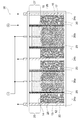
- FIG. 3 the parallel stacked nickel-zinc battery 30 includes a first positive electrode chamber 24 a (comprising a positive electrode current collector 13 coated on one side of the positive electrode 12) / separator 20 / first negative electrode chamber 26 a (coated on both sides of the negative electrode 16.
- Negative electrode current collector 17 / separator 20 / second positive electrode chamber 24b (including positive electrode current collector 13 coated on both sides of positive electrode 12) / separator 20 / second negative electrode chamber 26b (negative electrode 16 coated on both sides)
- the negative electrode current collector 17 is provided) / the separator 20 / the third positive electrode chamber 24c (including the positive electrode current collector 13 on which the positive electrode 12 is coated on one side) is arranged in this order.
- the constituent elements of the positive electrode chambers 24a, 24b and 24c are the same as those of the positive electrode chamber 24 in FIG. Since it is the same as that of the negative electrode chamber 26 of FIG.
- the nickel zinc battery of the present invention can be used in various applications in order to make use of its excellent power storage capacity.
- Examples of preferable applications to which the nickel zinc battery of the present invention can be applied include UPS (uninterruptible power supply), HEMS (home energy management system), stores (for example, 24-hour store), BEMS (building energy). ⁇ Management system), hospital, data center, radio base station, ship (in the harbor), FEMS (factory energy management system), smart community, CEMS (cluster / community energy management system), Examples include mega solar and wind farms (wind power plants).
- the nickel-zinc battery of the present invention can exhibit a function as a backup power source and a peak cut / shift function.
- Nickel zinc batteries for example, cells having a capacity of 40 to 200 Wh
- nickel zinc battery modules for example, more than 6 cells
- nickel zinc battery systems for example, more than 6 cells
- Nickel zinc battery module and the like, and an optimum form may be adopted depending on the application.
- the nickel-zinc battery of the present invention may be configured not only as a nickel-zinc battery alone but also as a battery system in cooperation with sunlight, or as a fuel cell (for example, a solid oxide fuel cell (SOFC) or a polymer fuel cell ( It may be configured to be used in conjunction with PEFC)).
- a fuel cell for example, a solid oxide fuel cell (SOFC) or a polymer fuel cell ( It may be configured to be used in conjunction with PEFC)
- the inorganic solid electrolyte body constituting the separator in the present invention can be in the form of a film or a layer.
- a separator with a porous substrate in which a film-like or layered inorganic solid electrolyte is formed on or in the porous substrate.
- a particularly preferred separator with a porous substrate comprises a porous substrate and a separator layer formed on and / or in the porous substrate, and the separator layer is layered as described above. It comprises double hydroxide (LDH).
- the separator layer does not have water permeability.
- the porous material may have water permeability due to the presence of pores, but the separator layer is densified with LDH to such an extent that it does not have water permeability.
- the separator layer is preferably formed on a porous substrate.
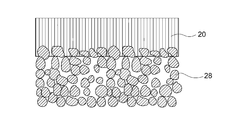
- the separator layer 20 is preferably formed as an LDH dense film on the porous substrate 28.
- LDH may also be formed on the surface of the porous substrate 28 and in the pores in the vicinity thereof as shown in FIG. 4 due to the nature of the porous substrate 28.
- FIG. 4 shows that is, the porous material may have water permeability due to the presence of pores, but the separator layer is densified with LDH to such an extent that it does not have water permeability.
- the separator layer is preferably formed on a porous substrate.
- the separator layer 20 is preferably formed as an LDH dense film on the porous substrate 28.
- LDH may also be formed on the surface of the porous substrate 28 and in the pores in the vicinity thereof as shown in FIG. 4 due to the nature
- LDH is densely formed in the porous substrate 28 (for example, the surface of the porous substrate 28 and the pores in the vicinity thereof), whereby at least one of the porous substrates 28 is formed.
- the part may constitute separator layer 20 '.
- the embodiment shown in FIG. 5 has a configuration in which the membrane equivalent portion of the separator layer 20 of the embodiment shown in FIG. 4 is removed, but is not limited to this, and is parallel to the surface of the porous substrate 28.
- a separator layer only needs to be present. In any case, since the separator layer is densified with LDH to such an extent that it does not have water permeability, it can have a specific function of having hydroxide ion conductivity but not water permeability.
- the porous substrate is preferably one that can form an LDH-containing separator layer on and / or in the porous substrate, and the material and porous structure are not particularly limited.
- an LDH-containing separator layer is formed on and / or in a porous substrate, but an LDH-containing separator layer is formed on a non-porous substrate and then non-porous by various known techniques.
- the porous substrate may be made porous.
- the porous base material has a porous structure having water permeability in that the electrolyte solution can reach the separator layer when incorporated into the battery as a battery separator.
- the porous substrate is preferably composed of at least one selected from the group consisting of ceramic materials, metal materials, and polymer materials. More preferably, the porous substrate is made of a ceramic material.
- the ceramic material include alumina, zirconia, titania, magnesia, spinel, calcia, cordierite, zeolite, mullite, ferrite, zinc oxide, silicon carbide, aluminum nitride, silicon nitride, and any combination thereof. More preferred are alumina, zirconia, titania, and any combination thereof, particularly preferred are alumina and zirconia, and most preferred is alumina.
- the metal material include aluminum and zinc.
- Preferred examples of the polymer material include polystyrene, polyethersulfone, polypropylene, epoxy resin, polyphenylene sulfide, and any combination thereof. It is more preferable to appropriately select a material excellent in alkali resistance as the resistance to the battery electrolyte from the various preferable materials described above.
- the porous substrate preferably has an average pore diameter of 0.001 to 1.5 ⁇ m, more preferably 0.001 to 1.25 ⁇ m, still more preferably 0.001 to 1.0 ⁇ m, and particularly preferably 0.001. 0.75 ⁇ m, most preferably 0.001 to 0.5 ⁇ m.
- the average pore diameter can be measured by measuring the longest distance of the pores based on an electron microscope (SEM) image of the surface of the porous substrate.
- the surface of the porous substrate preferably has a porosity of 10 to 60%, more preferably 15 to 55%, still more preferably 20 to 50%. By setting it within these ranges, it is possible to form an LDH-containing separator layer that is so dense that it does not have water permeability while ensuring desired water permeability in the porous substrate.
- the porosity of the surface of the porous substrate is adopted because it is easy to measure the porosity using the image processing described below, and the porosity of the surface of the porous substrate. This is because it can be said that it generally represents the porosity inside the porous substrate. That is, if the surface of the porous substrate is dense, the inside of the porous substrate can be said to be dense as well.
- the porosity of the surface of the porous substrate can be measured as follows by a technique using image processing. That is, 1) An electron microscope (SEM) image of the surface of the porous substrate (acquisition of 10,000 times or more) is obtained, and 2) a grayscale SEM image is read using image analysis software such as Photoshop (manufactured by Adobe). 3) Create a black-and-white binary image by the procedure of [Image] ⁇ [Tonal Correction] ⁇ [Turn Tone], and 4) The value obtained by dividing the number of pixels occupied by the black part by the total number of pixels in the image Rate (%).
- the porosity measurement by this image processing is preferably performed for a 6 ⁇ m ⁇ 6 ⁇ m region on the surface of the porous substrate. In order to obtain a more objective index, three arbitrarily selected regions are used. It is more preferable to employ the average value of the obtained porosity.
- the separator layer is formed on the porous substrate and / or in the porous substrate, preferably on the porous substrate.
- the separator layer 20 is in the form of an LDH dense film, which is typically made from LDH.
- the separator layer 20 ′ is formed in the porous substrate 28 as shown in FIG. 5, the surface of the porous substrate 28 (typically the surface of the porous substrate 28 and the vicinity thereof). Since the LDH is densely formed in the pores), the separator layer 20 ′ is typically composed of at least a part of the porous substrate 28 and LDH.
- the separator layer 20 ′ shown in FIG. 5 can be obtained by removing a portion corresponding to the film in the separator layer 20 shown in FIG. 4 by a known method such as polishing or cutting.
- the separator layer does not have water permeability.
- the separator layer does not allow water to pass through even if one side of the separator layer is contacted with water at 25 ° C. for one week. That is, the separator layer is densified with LDH to such an extent that it does not have water permeability.
- an appropriate repair agent for example, epoxy resin
- Such a repair agent need not necessarily have hydroxide ion conductivity.
- the surface of the separator layer (typically the LDH dense film) preferably has a porosity of 20% or less, more preferably 15% or less, still more preferably 10% or less, and particularly preferably 7%. It is as follows. It means that the lower the porosity of the surface of the separator layer, the higher the density of the separator layer (typically the LDH dense film), which is preferable.
- the porosity of the surface of the separator layer is adopted because it is easy to measure the porosity using the image processing described below, and the porosity of the surface of the separator layer is determined inside the separator layer. It is because it can be said that the porosity of is generally expressed.
- the porosity of the surface of the separator layer can be measured as follows by a technique using image processing. That is, 1) An electron microscope (SEM) image (10,000 times or more magnification) of the surface of the separator layer is acquired, and 2) a gray-scale SEM image is read using image analysis software such as Photoshop (manufactured by Adobe). ) Create a black-and-white binary image by the procedure of [Image] ⁇ [Tone Correction] ⁇ [2 Gradation], and 4) Porosity (the value obtained by dividing the number of pixels occupied by the black part by the total number of pixels in the image) %).
- SEM electron microscope
- Photoshop manufactured by Adobe
- the porosity measurement by this image processing is preferably performed for a 6 ⁇ m ⁇ 6 ⁇ m region on the surface of the separator layer. In order to obtain a more objective index, it is obtained for three arbitrarily selected regions. It is more preferable to adopt the average value of the porosity.
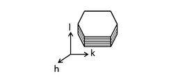
- the layered double hydroxide is composed of an aggregate of a plurality of plate-like particles (that is, LDH plate-like particles), and the plurality of plate-like particles are substantially the same as the surface of the porous substrate (substrate surface). It is preferably oriented in a direction that intersects perpendicularly or diagonally.
- this embodiment is a particularly preferable and feasible embodiment when the separator layer 20 is formed as an LDH dense film on the porous substrate 28.
- LDH is densely formed in the porous substrate 28 (typically in the surface of the porous substrate 28 and in the pores in the vicinity thereof), whereby at least a part of the porous substrate 28 forms the separator layer 20 ′. This can be realized even in the case of configuration.
- the LDH crystal is known to have the form of a plate-like particle having a layered structure as shown in FIG. 6, but the above-mentioned substantially vertical or oblique orientation is obtained by using an LDH-containing separator layer (for example, an LDH dense film).
- an LDH-containing separator layer for example, an LDH dense film
- the hydroxide ion conductivity in the direction in which the LDH plate-like particles are oriented is perpendicular to this. This is because there is a conductivity anisotropy that is much higher than the conductivity in the direction.
- the present inventors have found that in an LDH oriented bulk body, the conductivity (S / cm) in the orientation direction is an order of magnitude higher than the conductivity (S / cm) in the direction perpendicular to the orientation direction. It has gained. That is, the substantially vertical or oblique alignment in the LDH-containing separator layer of the present invention indicates the conductivity anisotropy that the LDH alignment body can have in the layer thickness direction (that is, the direction perpendicular to the surface of the separator layer or the porous substrate). As a result, the conductivity in the layer thickness direction can be maximized or significantly increased. In addition, since the LDH-containing separator layer has a layer form, lower resistance can be realized than a bulk form LDH. An LDH-containing separator layer having such an orientation is easy to conduct hydroxide ions in the layer thickness direction. In addition, since it is densified, it is extremely suitable for a separator that requires high conductivity and denseness in the layer thickness direction.
- the LDH plate-like particles are highly oriented in a substantially vertical direction in the LDH-containing separator layer (typically an LDH dense film).
- LDH-containing separator layer typically an LDH dense film.
- This high degree of orientation is confirmed by the fact that when the surface of the separator layer is measured by an X-ray diffraction method, the peak of the (003) plane is not substantially detected or smaller than the peak of the (012) plane. (However, when a porous substrate in which a diffraction peak is observed at the same position as the peak due to the (012) plane is used, the peak of the (012) plane due to the LDH plate-like particle is used. This is not the case).
- This characteristic peak characteristic indicates that the LDH plate-like particles constituting the separator layer are oriented in a substantially vertical direction (that is, a vertical direction or an oblique direction similar thereto, preferably a vertical direction) with respect to the separator layer. That is, the (003) plane peak is known as the strongest peak observed when X-ray diffraction is performed on non-oriented LDH powder. In the oriented LDH-containing separator layer, the LDH plate-like particles are separated from the separator. By being oriented in a direction substantially perpendicular to the layer, the peak of the (003) plane is not substantially detected or detected smaller than the peak of the (012) plane.
- the c-axis direction (00l) plane (l is 3 and 6) to which the (003) plane belongs is a plane parallel to the layered structure of the LDH plate-like particles.
- the LDH layered structure also faces in a substantially vertical direction.
- the separator layer surface is measured by an X-ray diffraction method, the (00l) plane (l is 3 and 6).
- the peak of) does not appear or becomes difficult to appear.
- the peak of the (003) plane tends to be stronger than the peak of the (006) plane when it is present. I can say that. Therefore, in the oriented LDH-containing separator layer, the (003) plane peak is substantially not detected or smaller than the (012) plane peak, suggesting a high degree of vertical orientation. It can be said that it is preferable.
- the separator layer preferably has a thickness of 100 ⁇ m or less, more preferably 75 ⁇ m or less, still more preferably 50 ⁇ m or less, particularly preferably 25 ⁇ m or less, and most preferably 5 ⁇ m or less.
- the separator layer is preferably formed as an LDH dense film on the porous substrate.
- the thickness of the separator layer corresponds to the thickness of the LDH dense film.
- the thickness of the separator layer corresponds to the thickness of the composite layer composed of at least part of the porous substrate and LDH, and the separator layer is porous.
- the thickness of the LDH alignment film is not particularly limited because it varies depending on the application, but in order to ensure a certain degree of hardness desired as a functional film such as a separator, the thickness is preferably 1 ⁇ m or more. Preferably it is 2 micrometers or more.
- the LDH separator with a porous substrate described above is (1) a porous substrate is prepared, and (2) a total of 0.20 to 0.40 mol / L of magnesium ions (Mg 2+ ) and aluminum ions (Al 3+ ).
- a separator comprising a layered double hydroxide by immersing the porous substrate in a raw material aqueous solution containing urea at a concentration and (3) hydrothermally treating the porous substrate in the raw material aqueous solution It can be produced by forming a layer on and / or in a porous substrate.
- the porous substrate is as described above, and is preferably composed of at least one selected from the group consisting of ceramic materials, metal materials, and polymer materials. More preferably, the porous substrate is made of a ceramic material.
- the ceramic material include alumina, zirconia, titania, magnesia, spinel, calcia, cordierite, zeolite, mullite, ferrite, zinc oxide, silicon carbide, aluminum nitride, silicon nitride, and any combination thereof. More preferred are alumina, zirconia, titania, and any combination thereof, particularly preferred are alumina and zirconia, and most preferred is alumina.
- the density of the LDH-containing separator layer tends to be improved.
- a polymer substrate having an anionized surface since the surface is anionized, LDH nuclei can be generated in anion-derived groups in the subsequent steps, and the growth and orientation in the substantially vertical direction of the LDH plate-like particles can be promoted.
- the polymer base material whose surface is anionized may be prepared by anionizing a polymer base material capable of anionization by a known method. In the anionization treatment, at least one selected from SO 3 ⁇ (sulfonated), OH ⁇ (hydroxylated) and CO 2 ⁇ (carboxylated) which can be taken as an anion of LDH is applied to the surface of the polymer substrate.
- the anionizable polymer base material desirably has alkali resistance as a resistance to the battery electrolyte.
- the anionizable polymer substrate is preferably composed of at least one selected from the group consisting of polystyrene, polyethersulfone, polypropylene, epoxy resin, and polyphenylene sulfide, and these polymer substrates are particularly sulfonated. Suitable for.
- the aromatic polymer base material is preferable in that it is easily anionized (particularly sulfonated).
- aromatic polymer base materials include, for example, polystyrene, polyethersulfone, epoxy resin, and polyphenylene sulfide.
- the sulfonated polymer base material may be immersed in a sulfonateable acid such as sulfuric acid (for example, concentrated sulfuric acid), fuming sulfuric acid, chlorosulfonic acid, and anhydrous sulfuric acid.
- a sulfonateable acid such as sulfuric acid (for example, concentrated sulfuric acid), fuming sulfuric acid, chlorosulfonic acid, and anhydrous sulfuric acid.
- the immersion in the sulfonateable acid may be performed at room temperature or at a high temperature (for example, 50 to 150 ° C.).
- a value T 1601 / T 1127 obtained by dividing the transmittance value T 1601 at 1601 cm ⁇ 1 derived from the phenyl group CC stretching vibration of the transmission spectrum by the transmittance value T 1127 at 1127 cm ⁇ 1 derived from the sulfonic acid group is It is preferably 0.920 or more, more preferably 0.930 or more, and still more preferably 0.940 or more.
- the value T 1601 of the transmittance of the absorption peaks seen in 1601 cm -1 are the same value regardless of the presence of sulfone group for an origin phenyl group CC stretching vibration absorption peaks seen in 1127Cm -1
- the transmittance value T 1127 is derived from a sulfonic acid group, the lower the sulfonic acid density, the lower the value. Therefore, the larger the value of T 1601 / T 1127 , the higher the density of LDH nuclei in which a large number of sulfonic acid groups exist on the surface of the polymer substrate and the sulfonic acid groups are incorporated as intermediate layer anions. And contributes to densification of the LDH-containing separator layer.
- the value of T 1601 / T 1127 can be set within the above range by appropriately adjusting the time of immersion in the sulfonateable acid.
- the immersion time is preferably 6 days or longer, more preferably 12 days or longer.
- the anionized polymer substrate is preferably washed with ion-exchanged water and then dried at room temperature or high temperature (for example, 30 to 50 ° C.).
- the porous substrate is immersed in the raw material aqueous solution in a desired direction (for example, horizontally or vertically).
- a desired direction for example, horizontally or vertically.
- the porous substrate may be suspended, floated, or disposed so as to be in contact with the bottom of the container.
- the porous substrate is suspended from the bottom of the container in the raw material aqueous solution.
- the material may be fixed.
- a jig that can set the porous substrate vertically on the bottom of the container may be placed.
- LDH is substantially perpendicular to or close to the porous substrate (that is, the LDH plate-like particles have their plate surfaces intersecting the surface (substrate surface) of the porous substrate substantially perpendicularly or obliquely. It is preferable to adopt a configuration or arrangement in which growth is performed in such a direction.
- the raw material aqueous solution contains magnesium ions (Mg 2+ ) and aluminum ions (Al 3+ ) at a predetermined total concentration, and contains urea. By the presence of urea, ammonia is generated in the solution by utilizing hydrolysis of urea, so that the pH value increases, and the coexisting metal ions form hydroxides to obtain LDH.
- the total concentration (Mg 2+ + Al 3+ ) of magnesium ions and aluminum ions contained in the raw material aqueous solution is preferably 0.20 to 0.40 mol / L, more preferably 0.22 to 0.38 mol / L, still more preferably The amount is 0.24 to 0.36 mol / L, particularly preferably 0.26 to 0.34 mol / L.
- concentration is within such a range, nucleation and crystal growth can proceed in a well-balanced manner, and an LDH-containing separator layer that is excellent not only in orientation but also in denseness can be obtained. That is, when the total concentration of magnesium ions and aluminum ions is low, crystal growth becomes dominant compared to nucleation, and the number of particles decreases and particle size increases. It is considered that the generation becomes dominant, the number of particles increases, and the particle size decreases.
- magnesium nitrate and aluminum nitrate are dissolved in the raw material aqueous solution, so that the raw material aqueous solution contains nitrate ions in addition to magnesium ions and aluminum ions.
- the molar ratio of urea to nitrate ions (NO 3 ⁇ ) (urea / NO 3 ⁇ ) in the raw material aqueous solution is preferably 2 to 6, and more preferably 4 to 5.
- the porous substrate is hydrothermally treated in the raw material aqueous solution, and the separator layer containing LDH is placed on the porous substrate and / or in the porous substrate. Let it form.
- This hydrothermal treatment is preferably carried out in a closed container at 60 to 150 ° C., more preferably 65 to 120 ° C., further preferably 65 to 100 ° C., and particularly preferably 70 to 90 ° C.
- the upper limit temperature of the hydrothermal treatment may be selected so that the porous substrate (for example, the polymer substrate) is not deformed by heat.
- the rate of temperature increase during the hydrothermal treatment is not particularly limited, and may be, for example, 10 to 200 ° C./h, preferably 100 to 200 ° C./h, more preferably 100 to 150 ° C./h.
- the hydrothermal treatment time may be appropriately determined according to the target density and thickness of the LDH-containing separator layer.
- the porous substrate After the hydrothermal treatment, it is preferable to take out the porous substrate from the sealed container and wash it with ion-exchanged water.
- the LDH-containing separator layer in the LDH-containing composite material produced as described above is one in which LDH plate-like particles are highly densified and are oriented in a substantially vertical direction advantageous for conduction. Therefore, it can be said that it is extremely suitable for a nickel-zinc battery in which the progress of zinc dendrite has become a major barrier to practical use.
- the LDH containing separator layer obtained by the said manufacturing method can be formed in both surfaces of a porous base material. For this reason, in order to make the LDH-containing composite material suitable for use as a separator, the LDH-containing separator layer on one side of the porous substrate is mechanically scraped after film formation, or on one side during film formation. It is desirable to take measures so that the LDH-containing separator layer cannot be formed.
- LDH dense body is a layered double hydroxide (LDH) dense body.
- LDH dense body may be produced by any method, an embodiment of a preferable production method will be described below. This production method is carried out by forming and firing LDH raw material powder typified by hydrotalcite to form an oxide fired body, regenerating it into a layered double hydroxide, and then removing excess water. . According to this method, a high-quality layered double hydroxide dense body having a relative density of 88% or more can be provided and produced easily and stably.
- M 2+ may be any divalent cation, and preferred examples include Mg 2+ , Ca 2+ and Zn 2+ , and more preferably Mg 2+ .
- M 3+ may be any trivalent cation, but preferred examples include Al 3+ or Cr 3+ , and more preferred is Al 3+ .
- a n- can be any anion, but preferred examples include OH - and CO 3 2- . Accordingly, the general formula is at least M 2+ is Mg 2+, include M 3+ is Al 3+, A n-is OH - and / or CO preferably contains 3 2-.
- n is an integer of 1 or more, preferably 1 or 2.
- x is 0.1 to 0.4, preferably 0.2 to 0.35.
- Such a raw material powder may be a commercially available layered double hydroxide product, or may be a raw material produced by a known method such as a liquid phase synthesis method using nitrate or chloride.
- the particle diameter of the raw material powder is not limited as long as a desired layered double hydroxide dense body is obtained, but the volume-based D50 average particle diameter is preferably 0.1 to 1.0 ⁇ m, more preferably 0.3. ⁇ 0.8 ⁇ m. This is because if the particle size of the raw material powder is too fine, the powder tends to aggregate, and there is a high possibility that pores will remain during molding, and if it is too large, the moldability will deteriorate.
- the raw material powder may be calcined to obtain an oxide powder.
- the calcining temperature at this time is somewhat different depending on the constituent M 2+ and M 3+ , but is preferably 500 ° C. or less, more preferably 380 to 460 ° C., and in a region where the raw material particle size does not change greatly.
- a molded body after molding and before firing (hereinafter referred to as a molded body) has a relative density of 43 to 65%, more preferably 45 to 60%, and still more preferably 47% to 58%. For example, it is preferably performed by pressure molding.
- the relative density of the molded body is calculated by calculating the density from the size and weight of the molded body and dividing by the theoretical density, but the weight of the molded body is affected by the adsorbed moisture.
- the relative density of the compact is preferably 26 to 40%, more preferably 29 to 36%.
- the relative density in the case of using oxide powder is based on the assumption that each metal element constituting the layered double hydroxide has changed to oxide by calcining, and the converted density obtained as a mixture of each oxide is the denominator. As sought.
- the pressure forming described as an example may be performed by a uniaxial press of a mold, or may be performed by cold isostatic pressing (CIP).
- CIP cold isostatic pressing
- mold by well-known methods, such as slip casting and extrusion molding, and it does not specifically limit about a shaping
- the raw material powder is calcined to obtain an oxide powder, it is limited to the dry molding method.
- the relative density of these compacts not only affects the strength of the resulting compact, but also affects the degree of orientation of the layered double hydroxides that usually have a plate shape.
- the relative density is preferably set within the above range.
- the molded body obtained in the above step is fired to obtain an oxide fired body.
- This firing is preferably carried out so that the oxide fired body has a weight of 57 to 65% of the weight of the compact and / or a volume of 70 to 76% or less of the volume of the compact.
- it is 57% or more of the weight of the molded product, it is difficult to generate a heterogeneous phase that cannot be regenerated during regeneration to a layered double hydroxide in the subsequent step, and when it is 65% or less, sufficient firing is performed in the subsequent step. Densify.
- the raw material powder is calcined to obtain an oxide powder
- the firing is preferably performed so that the oxide fired body has a relative density of 20 to 40% in terms of oxide, more preferably 20 to 35. %, More preferably 20-30%.
- the relative density in terms of oxide means that each metal element constituting the layered double hydroxide is changed to an oxide by firing, and the converted density obtained as a mixture of each oxide is used as the denominator. It is the obtained relative density.
- a preferable baking temperature for obtaining the oxide fired body is 400 to 850 ° C., more preferably 700 to 800 ° C. It is preferable to hold at a firing temperature within this range for 1 hour or more, and a more preferable holding time is 3 to 10 hours. Further, in order to prevent moisture and carbon dioxide from being released due to rapid temperature rise and cracking the molded body, the temperature rise for reaching the firing temperature is preferably performed at a rate of 100 ° C./h or less.
- the total firing time from the temperature rise to the temperature fall (100 ° C. or less) is preferably secured for 20 hours or more, more preferably 30 to 70 hours, and further preferably 35 to 65 hours.
- the layered double hydroxide is obtained by holding the calcined oxide obtained in the above step in the aqueous solution containing the n-valent anion (A n ⁇ ) or just above it. It regenerates into a product, thereby obtaining a layered double hydroxide solidified body rich in moisture. That is, the layered double hydroxide solidified body obtained by this production method inevitably contains excess moisture.
- the anion contained in the aqueous solution may be the same kind of anion as that contained in the raw material powder, or may be a different kind of anion.
- the oxide fired body is held in an aqueous solution or immediately above the aqueous solution by a hydrothermal synthesis method in a sealed container, and an example of such a sealed container is a sealed container made of Teflon (registered trademark). More preferably, it is a closed container provided with a jacket made of stainless steel or the like on the outside thereof.
- the layered double hydroxide is preferably formed by maintaining the oxide fired body at 20 ° C. or more and less than 200 ° C. so that at least one surface of the oxide fired body is in contact with the aqueous solution, and a more preferable temperature is 50 to 180. And a more preferred temperature is 100 to 150 ° C.
- the oxide sintered body is preferably held for 1 hour or more at such a layered double hydroxide formation temperature, more preferably 2 to 50 hours, and further preferably 5 to 20 hours. With such a holding time, it is possible to avoid or reduce the occurrence of a heterogeneous phase by sufficiently regenerating the layered double hydroxide.
- the holding time is not particularly problematic if it is too long, but it may be set in a timely manner with emphasis on efficiency.
- the fired oxide body may be submerged in the aqueous solution, or the treatment may be performed in a state where at least one surface is in contact with the aqueous solution using a jig.
- the amount of excess water is small compared to complete submergence, so that the subsequent steps may be completed in a short time.
- the amount of the aqueous solution is too small, cracks are likely to occur. Therefore, it is preferable to use moisture equal to or greater than the weight of the fired body.
- the layered double hydroxide dense body of the present invention is obtained.
- the step of removing excess water is preferably performed in an environment of 300 ° C. or lower and an estimated relative humidity of 25% or higher at the maximum temperature of the removal step.
- the preferred temperature is 50 to 250 ° C., more preferably 100 to 200 ° C.
- a more preferable relative humidity at the time of dehydration is 25 to 70%, and further preferably 40 to 60%. Dehydration may be performed at room temperature, and there is no problem as long as the relative humidity is within a range of 40 to 70% in a normal indoor environment.
- Example 1 Production and evaluation of LDH separator with porous substrate (1) Production of porous substrate Boehmite (manufactured by Sasol, DISPAL 18N4-80), methylcellulose, and ion-exchanged water (boehmite): (methylcellulose) : (Ion-exchanged water) mass ratio was 10: 1: 5, and then kneaded. The obtained kneaded product was subjected to extrusion molding using a hand press and molded into a plate shape having a size sufficiently exceeding 5 cm ⁇ 8 cm and a thickness of 0.5 cm. The obtained molded body was dried at 80 ° C. for 12 hours and then calcined at 1150 ° C. for 3 hours to obtain an alumina porous substrate. The porous substrate thus obtained was cut into a size of 5 cm ⁇ 8 cm.
- Boehmite manufactured by Sasol, DISPAL 18N4-80
- methylcellulose methylcellulose
- the porosity of the surface of the porous substrate was measured by a technique using image processing, and it was 24.6%.
- the porosity is measured by 1) observing the surface microstructure with an accelerating voltage of 10 to 20 kV using a scanning electron microscope (SEM, JSM-6610LV, manufactured by JEOL Co., Ltd.). SEM) image (magnification of 10,000 times or more) is obtained, 2) a grayscale SEM image is read using image analysis software such as Photoshop (manufactured by Adobe), etc.
- the average pore diameter of the porous substrate was measured, it was about 0.1 ⁇ m.
- the average pore diameter was measured by measuring the longest distance of the pores based on an electron microscope (SEM) image of the surface of the porous substrate.
- the magnification of the electron microscope (SEM) image used for this measurement is 20000 times, and all the obtained pore diameters are arranged in order of size, and the top 15 points and the bottom 15 points from the average value, and 30 points per visual field in total.
- the average value for two visual fields was calculated to obtain the average pore diameter.
- the length measurement function of SEM software was used.
- magnesium nitrate hexahydrate (Mg (NO 3) 2 ⁇ 6H 2 O, manufactured by Kanto Chemical Co., Inc.), aluminum nitrate nonahydrate (Al (NO 3) 3 ⁇ 9H 2 O, manufactured by Kanto Chemical Co., Ltd.) and urea ((NH 2 ) 2 CO, manufactured by Sigma-Aldrich) were prepared.
- Mg (NO 3) 2 ⁇ 6H 2 O manufactured by Kanto Chemical Co., Inc.
- Al (NO 3) 3 ⁇ 9H 2 O manufactured by Kanto Chemical Co., Ltd.
- urea ((NH 2 ) 2 CO, manufactured by Sigma-Aldrich)
- ion exchange water was added to make a total volume of 75 ml.
- the substrate is taken out from the sealed container, washed with ion-exchanged water, dried at 70 ° C. for 10 hours, and a dense layer of layered double hydroxide (hereinafter referred to as LDH) (hereinafter referred to as a membrane sample). ) was obtained on a substrate.
- LDH layered double hydroxide
- the thickness of the obtained film sample was about 1.5 ⁇ m.
- a composite material sample was obtained.
- the LDH film was formed on both surfaces of the porous substrate, the LDH film on one surface of the porous substrate was mechanically scraped to give the composite material a form as a separator.
- FIG. 9 shows an SEM image (secondary electron image) of the surface microstructure of the obtained film sample.
- the cross section of the composite material sample was polished by CP polishing to form a polished cross section, and the microstructure of the polished cross section was observed with a scanning electron microscope (SEM) at an acceleration voltage of 10 to 20 kV.
- SEM scanning electron microscope
- the porosity of the surface of the membrane was measured for the membrane sample by a technique using image processing.
- the porosity is measured by 1) observing the surface microstructure with a scanning electron microscope (SEM, JSM-6610LV, manufactured by JEOL) at an acceleration voltage of 10 to 20 kV, and observing an electron microscope (SEM) on the surface of the film.
- SEM scanning electron microscope
- the porosity of the polished cross section of the film sample was also measured.
- the measurement of the porosity of the polished cross section is the same as that described above except that an electron microscope (SEM) image (magnification of 10,000 times or more) of the cross-section polished surface in the thickness direction of the film was obtained according to the procedure shown in (5b) above. It carried out similarly to the porosity of the film
- the measurement of the porosity was performed on the film portion of the alignment film cross section.
- the porosity calculated from the cross-sectional polished surface of the film sample is 3.5% on average (average value of the three cross-sectional polished surfaces), and a very high-density film is formed on the porous substrate. It was confirmed that
- Denseness determination test A denseness determination test was performed as follows in order to confirm that the film sample has a denseness that does not have water permeability. First, as shown in FIG. 11A, the composite material sample 120 obtained in (1) above (cut to 1 cm ⁇ 1 cm square) has a center of 0.5 cm ⁇ 0.5 cm square on the film sample side. The silicon rubber 122 provided with the opening 122a was adhered, and the obtained laminate was adhered between two acrylic containers 124 and 126. The bottom of the acrylic container 124 disposed on the silicon rubber 122 side is pulled out, whereby the silicon rubber 122 is bonded to the acrylic container 124 with the opening 122a open.
- the acrylic container 126 disposed on the porous substrate side of the composite material sample 120 has a bottom, and ion-exchanged water 128 is contained in the container 126.
- Al and / or Mg may be dissolved in the ion exchange water. That is, by assembling the components upside down after assembly, the constituent members are arranged so that the ion exchange water 128 is in contact with the porous substrate side of the composite material sample 120. After assembling these components, the total weight was measured. Needless to say, the container 126 has a closed vent hole (not shown) and is opened after being turned upside down. The assembly was placed upside down as shown in FIG. 11B and held at 25 ° C. for 1 week, and then the total weight was measured again.
- the membrane sample (that is, the functional membrane) has high density so as not to have water permeability.
- Example 2 Production and evaluation of nickel zinc battery (1) Preparation of separator with porous substrate Hydrotalcite membrane on alumina substrate (size: 5 cm ⁇ ) as a separator with porous substrate by the same procedure as in Example 1. 8 cm) was prepared.
- Nickel hydroxide particles to which zinc and cobalt were added so as to form a solid solution were prepared.
- the nickel hydroxide particles were coated with cobalt hydroxide to obtain a positive electrode active material.
- the obtained positive electrode active material was mixed with a 2% aqueous solution of carboxymethyl cellulose to prepare a paste.
- the paste obtained above is uniformly applied to a current collector made of a nickel metal porous substrate having a porosity of about 95% and dried so that the porosity of the positive electrode active material is 50%.
- a positive electrode plate coated over an area of 5 cm ⁇ 5 cm was obtained. At this time, the coating amount was adjusted so that nickel hydroxide particles corresponding to 4 Ah were included in the active material.
- a rectangular parallelepiped case body made of ABS resin with the case top lid removed was prepared.
- a separator with a porous substrate (a hydrotalcite film on an alumina substrate) was inserted near the center of the case body, and three sides thereof were fixed to the inner wall of the case body using a commercially available adhesive.
- the positive electrode plate and the negative electrode plate were inserted into the positive electrode chamber and the negative electrode chamber, respectively.
- the positive electrode plate and the negative electrode plate were arranged so that the positive electrode current collector and the negative electrode current collector were in contact with the inner wall of the case body.
- a 6 mol / L aqueous KOH solution in an amount that sufficiently hides the positive electrode active material coating portion was injected into the positive electrode chamber as an electrolyte.
- the liquid level in the positive electrode chamber was about 5.2 cm from the case bottom.
- the negative electrode chamber not only the negative electrode active material coating part was sufficiently hidden, but also an excessive amount of 6 mol / L KOH aqueous solution was injected as an electrolyte considering the amount of water expected to decrease during charging. .
- the liquid level in the negative electrode chamber was about 6.5 cm from the case bottom.
- the terminal portions of the positive electrode current collector and the negative electrode current collector were connected to external terminals at the top of the case.
- the case upper lid was fixed to the case body by heat sealing, and the battery case container was sealed. Thus, a nickel zinc battery was obtained.
- the positive electrode chamber and the negative electrode The space equivalent to 3 cm above the chamber can be said to be the positive electrode side excess space and the negative electrode side excess space.
- the manufactured nickel zinc battery was subjected to constant current charging for 10 hours at a current of 0.4 mA corresponding to 0.1 C with a design capacity of 4 Ah. After charging, no deformation of the case or leakage of the electrolyte was observed. When the amount of the electrolyte after charging was observed, the electrolyte level in the positive electrode chamber was about 7.5 cm from the bottom of the case, and the electrolyte level in the negative electrode chamber was about 5.2 cm from the bottom of the case. It was. Although the positive electrode chamber electrolyte increased and the negative electrode chamber electrolyte decreased due to charging, there was sufficient electrolyte in the negative electrode active material coating part, and the applied positive electrode active material and negative electrode active material were charged and discharged. The electrolyte that causes a sufficient charge / discharge reaction could be held in the case.
Abstract
Description
前記正極が浸漬される、アルカリ金属水酸化物を含んでなる正極電解液と、
亜鉛及び/又は酸化亜鉛を含んでなる負極と、
前記負極が浸漬される、アルカリ金属水酸化物を含んでなる負極電解液と、
前記正極、前記正極電解液、前記負極、及び前記負極電解液を収容する密閉容器と、
前記密閉容器内に、前記正極及び前記正極電解液を収容する正極室と、前記負極及び前記負極電解液を収容する負極室とを区画するように設けられ、水酸化物イオン伝導性を有するが透水性を有しないセパレータと、
を備えてなる、ニッケル亜鉛電池が提供される。 According to one aspect of the invention, a positive electrode comprising nickel hydroxide and / or nickel oxyhydroxide,
A positive electrode electrolyte solution comprising an alkali metal hydroxide, in which the positive electrode is immersed;
A negative electrode comprising zinc and / or zinc oxide;
A negative electrode electrolyte solution comprising an alkali metal hydroxide, in which the negative electrode is immersed;
A sealed container containing the positive electrode, the positive electrode electrolyte, the negative electrode, and the negative electrode electrolyte;
In the sealed container, provided to partition the positive electrode chamber containing the positive electrode and the positive electrode electrolyte solution and the negative electrode chamber containing the negative electrode and the negative electrode electrolyte solution, and has hydroxide ion conductivity. A separator having no water permeability;
There is provided a nickel zinc battery comprising:
図1に、本発明によるニッケル亜鉛電池の一例を模式的に示す。図1に示されるニッケル亜鉛電池は充電が行われる前の初期状態を示しており、放電末状態に相当する。もっとも、本発明のニッケル亜鉛電池は満充電状態で構成されてもよいのはいうまでもない。図1に示されるように、本発明によるニッケル亜鉛電池10は、正極12、正極電解液14、負極16、負極電解液18、及びセパレータ20を密閉容器22内に備えてなる。正極12は、水酸化ニッケル及び/又はオキシ水酸化ニッケルを含んでなる。正極電解液14はアルカリ金属水酸化物を含んでなり、正極12が浸漬される。負極16は亜鉛及び/又は酸化亜鉛を含んでなる。負極電解液18はアルカリ金属水酸化物を含んでなり、負極16が浸漬される。密閉容器22は、正極12、正極電解液14、負極16、及び負極電解液18を収容する。正極12及び正極電解液14は必ずしも分離している必要はなく、正極12と正極電解液14が混合された正極合材として構成されてもよい。同様に、負極16及び負極電解液18は必ずしも分離している必要はなく、負極16と負極電解液18が混合された負極合材として構成されてもよい。所望により、正極集電体13が正極12に接触して設けられる。また、所望により、負極集電体17が負極16に接触して設けられる。 Nickel Zinc Battery FIG. 1 schematically shows an example of a nickel zinc battery according to the present invention. The nickel zinc battery shown in FIG. 1 shows an initial state before charging, and corresponds to a discharged state. However, it goes without saying that the nickel-zinc battery of the present invention may be configured in a fully charged state. As shown in FIG. 1, a
‐ 正極: Ni(OH)2+OH-→NiOOH+H2O+e-
‐ 負極: ZnO+H2O+2e-→Zn+2OH- The
-Positive electrode: Ni (OH) 2 + OH − → NiOOH + H 2 O + e −
-Negative electrode: ZnO + H 2 O + 2e − → Zn + 2OH −
‐ ZnOの溶解反応: ZnO+H2O+2OH-→Zn(OH)4 2-
‐ Znの析出反応: Zn(OH)4 2-+2e-→Zn+4OH- However, the negative electrode reaction is composed of the following two reactions.
-ZnO dissolution reaction: ZnO + H 2 O + 2OH − → Zn (OH) 4 2−
- precipitation reaction of Zn: Zn (OH) 4 2- + 2e - → Zn + 4OH -
セパレータ20は水酸化物イオン伝導性を有するが透水性を有しない部材であり、典型的には板状、膜状又は層状の形態である。セパレータ20は、密閉容器22内に設けられ、正極12及び正極電解液14を収容する正極室24と、負極16及び負極電解液18を収容する負極室26とを区画する。 The
正極12は水酸化ニッケル及び/又はオキシ水酸化ニッケルを含んでなる。例えば、ニッケル亜鉛電池を図1に示されるような放電末状態で構成する場合には正極12として水酸化ニッケルを用いればよく、図2に示されるような満充電状態で構成する場合には正極12としてオキシ水酸化ニッケルを用いればよい。水酸化ニッケル及びオキシ水酸化ニッケル(以下、水酸化ニッケル等という)は、ニッケル亜鉛電池に一般的に用いられている正極活物質であり、典型的には粒子形態である。水酸化ニッケル等には、その結晶格子中にニッケル以外の異種元素が固溶されていてもよく、それにより高温下での充電効率の向上が図れる。このような異種元素の例としては、亜鉛及びコバルトが挙げられる。また、水酸化ニッケル等はコバルト系成分と混合されたものであってもよく、そのようなコバルト系成分の例としては、金属コバルトやコバルト酸化物(例えば一酸化コバルト)の粒状物が挙げられる。さらに、水酸化ニッケル等の粒子(異種元素が固溶されていてよい)の表面をコバルト化合物で被覆してもよく、そのようなコバルト化合物の例としては、一酸化コバルト、2価のα型水酸化コバルト、2価のβ型水酸化コバルト、2価を超える高次コバルトの化合物、及びそれらの任意の組合せが挙げられる。 The
負極16は亜鉛及び/又は酸化亜鉛を含んでなる。亜鉛は、負極に適した電気化学的活性を有するものであれば、亜鉛金属、亜鉛化合物及び亜鉛合金のいずれの形態で含まれていてもよい。負極材料の好ましい例としては、酸化亜鉛、亜鉛金属、亜鉛酸カルシウム等が挙げられるが、亜鉛金属及び酸化亜鉛の混合物がより好ましい。負極16はゲル状に構成してもよいし、電解液と混合して負極合材としてもよい。例えば、負極活物質に電解液及び増粘剤を添加することにより容易にゲル化した負極を得ることができる。増粘剤の例としては、ポリビニルアルコール、ポリアクリル酸塩、CMC、アルギン酸等が挙げられるが、ポリアクリル酸が強アルカリに対する耐薬品性に優れているため好ましい。 The
正極電解液14及び負極電解液18はアルカリ金属水酸化物を含んでなる。すなわち、アルカリ金属水酸化物を含む水溶液が正極電解液14及び負極電解液18として用いられる。アルカリ金属水酸化物の例としては、水酸化カリウム、水酸化ナトリウム、水酸化リチウム、水酸化アンモニウム等が挙げられるが、水酸化カリウムがより好ましい。亜鉛合金の自己溶解を抑制するために、電解液中に酸化亜鉛、水酸化亜鉛等の亜鉛化合物を添加してもよい。前述のとおり、正極電解液14及び負極電解液18は正極12及び/又は負極16と混合させて正極合材及び/又は負極合材の形態で存在させてもよい。また、電解液の漏洩を防止するために電解液をゲル化してもよい。ゲル化剤としては電解液の溶媒を吸収して膨潤するようなポリマーを用いるのが望ましく、ポリエチレンオキサイド,ポリビニルアルコール,ポリアクリルアミドなどのポリマーやデンプンが用いられる。 The electrolyte
密閉容器22は、正極12、正極電解液14、負極16、及び負極電解液18を密閉収容する容器であり、液密性及び気密性を有する構造を有する。密閉容器の材質は水酸化カリウム等のアルカリ金属水酸化物に対する耐性を有するものであれば特に限定されず、ポリオレフィン樹脂、ABS樹脂、変性ポリフェニレンエーテル等の樹脂製であるのが好ましく、より好ましくはABS樹脂又は変性ポリフェニレンエーテルである。密閉容器22にはセパレータ20が様々な手法で固定されてよいが、水酸化カリウム等のアルカリ金属水酸化物に対する耐性を有する接着剤により固定されるのが好ましい。また、ポリオレフィン樹脂製の密閉容器22を用いた場合には熱融着によるセパレータ20の固定も好ましい。 The
図1に示されるニッケル亜鉛電池10は1対の正極12及び負極16を備えたものであるが、密閉容器22内に正極12及び負極16を2対以上備えた構成としてもよい。この場合、正極12及び負極16を交互に並置して並列積層型のニッケル亜鉛電池に構成するのが好ましい。そのような並列積層型ニッケル亜鉛電池の一例が図3に示される。図3に並列積層型ニッケル亜鉛電池30は、第1正極室24a(正極12を片面塗工した正極集電体13を備える)/セパレータ20/第1負極室26a(負極16を両面塗工した負極集電体17を備える)/セパレータ20/第2正極室24b(正極12を両面塗工した正極集電体13を備える)/セパレータ20/第2負極室26b(負極16を両面塗工した負極集電体17を備える)/セパレータ20/第3正極室24c(正極12を片面塗工した正極集電体13を備える)が順に並んだ構成を有している。なお、図3において、正極室24a,24b及び24cの構成要素は図1の正極室24の構成要素と同様のため図1と同じ符号を付してあり、負極室26a及び26bの構成要素は図1の負極室26の構成要素と同様のため図1と同じ符号を付してある。このように、正極室、セパレータ及び負極室をこの順に所望の回数繰り返して適宜配置することで、所望の数の正極及び負極を備えた並列積層型ニッケル亜鉛電池を構成することができる。 Parallel-stacked nickel-zinc battery The nickel-
本発明のニッケル亜鉛電池はその優れた蓄電能力を活かすべく様々な用途に利用することができる。本発明のニッケル亜鉛電池が適用可能な好ましい用途の例としては、UPS(無停電電源装置)、HEMS(ホーム・エネルギー・マネジメント・システム)、店舗(例えば24時間営業ストア)、BEMS(ビルディング・エネルギー・マネジメント・システム)、病院、データセンター、無線基地局、(港湾内における)船舶、FEMS(ファクトリー・エネルギー・マネジメント・システム)、スマート・コミュニティ、CEMS(クラスター/コミュニティ・エネルギー・マネジメント・システム)、メガソーラー、ウィンドファーム(風力発電所)等が挙げられる。これらの用途において、本発明のニッケル亜鉛電池は、バックアップ電源としての機能やピークカット/シフトの機能を発揮することができる。上記の好ましい用途はいずれも定置型電池に適したものであり、それ故、天地無用で且つ安定した状態(例えば振動が少ない状態)での取り扱いが望まれるニッケル亜鉛電池に特に適しているといえる。これらの用途向けのニッケル亜鉛電池の形態としては、ニッケル亜鉛セル(例えば容量が40~200Whのセル)、ニッケル亜鉛電池モジュール(例えば6個超のセル)、ニッケル亜鉛電池システム(例えば6個超のニッケル亜鉛電池モジュール)等が挙げられ、用途に応じて最適な形態を採用すればよい。本発明のニッケル亜鉛電池は、ニッケル亜鉛電池単体のみでなく、太陽光と連携した電池システムとして構成されてもよいし、燃料電池(例えば固体電解質型燃料電池(SOFC)や高分子型燃料電池(PEFC))と併設して使用するように構成されてもよい。 Applications The nickel zinc battery of the present invention can be used in various applications in order to make use of its excellent power storage capacity. Examples of preferable applications to which the nickel zinc battery of the present invention can be applied include UPS (uninterruptible power supply), HEMS (home energy management system), stores (for example, 24-hour store), BEMS (building energy).・ Management system), hospital, data center, radio base station, ship (in the harbor), FEMS (factory energy management system), smart community, CEMS (cluster / community energy management system), Examples include mega solar and wind farms (wind power plants). In these applications, the nickel-zinc battery of the present invention can exhibit a function as a backup power source and a peak cut / shift function. All of the above preferred applications are suitable for stationary batteries, and are therefore particularly suitable for nickel-zinc batteries that are not used upside down and are desired to be handled in a stable state (for example, with little vibration). . Nickel zinc batteries (for example, cells having a capacity of 40 to 200 Wh), nickel zinc battery modules (for example, more than 6 cells), nickel zinc battery systems (for example, more than 6 cells) for these applications Nickel zinc battery module) and the like, and an optimum form may be adopted depending on the application. The nickel-zinc battery of the present invention may be configured not only as a nickel-zinc battery alone but also as a battery system in cooperation with sunlight, or as a fuel cell (for example, a solid oxide fuel cell (SOFC) or a polymer fuel cell ( It may be configured to be used in conjunction with PEFC)).
前述のとおり、本発明においてセパレータを構成する無機固体電解質体は膜状又は層状の形態であることができる。この場合、膜状又は層状の無機固体電解質体が多孔質基材上又はその中に形成されてなる、多孔質基材付きセパレータとするのが好ましい。特に好ましい多孔質基材付きセパレータは、多孔質基材と、この多孔質基材上及び/又は多孔質基材中に形成されるセパレータ層とを備えてなり、セパレータ層が前述したような層状複水酸化物(LDH)を含んでなるものである。セパレータ層は透水性を有しない。すなわち、多孔質材料は孔の存在により透水性を有しうるが、セパレータ層は透水性を有しない程にまでLDHで緻密化されている。セパレータ層は多孔質基材上に形成されるのが好ましい。例えば、図4に示されるように、多孔質基材28上にセパレータ層20がLDH緻密膜として形成されるのが好ましい。この場合、多孔質基材28の性質上、図4に示されるように多孔質基材28の表面及びその近傍の孔内にもLDHが形成されてよいのはいうまでもない。あるいは、図5に示されるように、多孔質基材28中(例えば多孔質基材28の表面及びその近傍の孔内)にLDHが緻密に形成され、それにより多孔質基材28の少なくとも一部がセパレータ層20’を構成するものであってもよい。この点、図5に示される態様は図4に示される態様のセパレータ層20における膜相当部分を除去した構成となっているが、これに限定されず、多孔質基材28の表面と平行にセパレータ層が存在していればよい。いずれにしても、セパレータ層は透水性を有しない程にまでLDHで緻密化されているため、水酸化物イオン伝導性を有するが透水性を有しないという特有の機能を有することができる。 LDH separator with porous substrate As described above, the inorganic solid electrolyte body constituting the separator in the present invention can be in the form of a film or a layer. In this case, it is preferable to use a separator with a porous substrate, in which a film-like or layered inorganic solid electrolyte is formed on or in the porous substrate. A particularly preferred separator with a porous substrate comprises a porous substrate and a separator layer formed on and / or in the porous substrate, and the separator layer is layered as described above. It comprises double hydroxide (LDH). The separator layer does not have water permeability. That is, the porous material may have water permeability due to the presence of pores, but the separator layer is densified with LDH to such an extent that it does not have water permeability. The separator layer is preferably formed on a porous substrate. For example, as shown in FIG. 4, the
多孔質基材は、前述したとおりであり、セラミックス材料、金属材料、及び高分子材料からなる群から選択される少なくとも1種で構成されるのが好ましい。多孔質基材は、セラミックス材料で構成されるのがより好ましい。この場合、セラミックス材料の好ましい例としては、アルミナ、ジルコニア、チタニア、マグネシア、スピネル、カルシア、コージライト、ゼオライト、ムライト、フェライト、酸化亜鉛、炭化ケイ素、窒化アルミニウム、窒化ケイ素、及びそれらの任意の組合せが挙げられ、より好ましくは、アルミナ、ジルコニア、チタニア、及びそれらの任意の組合せであり、特に好ましくはアルミナ及びジルコニアであり、最も好ましくはアルミナである。これらの多孔質セラミックスを用いるとLDH含有セパレータ層の緻密性を向上しやすい傾向がある。セラミックス材料製の多孔質基材を用いる場合、超音波洗浄、イオン交換水での洗浄等を多孔質基材に施すのが好ましい。 (1) Preparation of porous substrate The porous substrate is as described above, and is preferably composed of at least one selected from the group consisting of ceramic materials, metal materials, and polymer materials. More preferably, the porous substrate is made of a ceramic material. In this case, preferable examples of the ceramic material include alumina, zirconia, titania, magnesia, spinel, calcia, cordierite, zeolite, mullite, ferrite, zinc oxide, silicon carbide, aluminum nitride, silicon nitride, and any combination thereof. More preferred are alumina, zirconia, titania, and any combination thereof, particularly preferred are alumina and zirconia, and most preferred is alumina. When these porous ceramics are used, the density of the LDH-containing separator layer tends to be improved. When using a porous substrate made of a ceramic material, it is preferable to subject the porous substrate to ultrasonic cleaning, cleaning with ion exchange water, and the like.
次に、多孔質基材を原料水溶液に所望の向きで(例えば水平又は垂直に)浸漬させる。多孔質基材を水平に保持する場合は、吊るす、浮かせる、容器の底に接するように多孔質基材を配置すればよく、例えば、容器の底から原料水溶液中に浮かせた状態で多孔質基材を固定としてもよい。多孔質基材を垂直に保持する場合は、容器の底に多孔質基材を垂直に設置できるような冶具を置けばよい。いずれにしても、多孔質基材にLDHを略垂直方向又はそれに近い方向(すなわちLDH板状粒子がそれらの板面が多孔質基材の表面(基材面)と略垂直に又は斜めに交差するような向きに)に成長させる構成ないし配置とするのが好ましい。原料水溶液は、マグネシウムイオン(Mg2+)及びアルミニウムイオン(Al3+)を所定の合計濃度で含み、かつ、尿素を含んでなる。尿素が存在することで尿素の加水分解を利用してアンモニアが溶液中に発生することによりpH値が上昇し、共存する金属イオンが水酸化物を形成することによりLDHを得ることができる。また、加水分解に二酸化炭素の発生を伴うため、陰イオンが炭酸イオン型のLDHを得ることができる。原料水溶液に含まれるマグネシウムイオン及びアルミニウムイオンの合計濃度(Mg2++Al3+)は0.20~0.40mol/Lが好ましく、より好ましくは0.22~0.38mol/Lであり、さらに好ましくは0.24~0.36mol/L、特に好ましくは0.26~0.34mol/Lである。このような範囲内の濃度であると核生成と結晶成長をバランスよく進行させることができ、配向性のみならず緻密性にも優れたLDH含有セパレータ層を得ることが可能となる。すなわち、マグネシウムイオン及びアルミニウムイオンの合計濃度が低いと核生成に比べて結晶成長が支配的となり、粒子数が減少して粒子サイズが増大する一方、この合計濃度が高いと結晶成長に比べて核生成が支配的となり、粒子数が増大して粒子サイズが減少するものと考えられる。 (2) Immersion in raw material aqueous solution Next, the porous substrate is immersed in the raw material aqueous solution in a desired direction (for example, horizontally or vertically). When the porous substrate is held horizontally, the porous substrate may be suspended, floated, or disposed so as to be in contact with the bottom of the container. For example, the porous substrate is suspended from the bottom of the container in the raw material aqueous solution. The material may be fixed. When the porous substrate is held vertically, a jig that can set the porous substrate vertically on the bottom of the container may be placed. In any case, LDH is substantially perpendicular to or close to the porous substrate (that is, the LDH plate-like particles have their plate surfaces intersecting the surface (substrate surface) of the porous substrate substantially perpendicularly or obliquely. It is preferable to adopt a configuration or arrangement in which growth is performed in such a direction. The raw material aqueous solution contains magnesium ions (Mg 2+ ) and aluminum ions (Al 3+ ) at a predetermined total concentration, and contains urea. By the presence of urea, ammonia is generated in the solution by utilizing hydrolysis of urea, so that the pH value increases, and the coexisting metal ions form hydroxides to obtain LDH. Further, since carbon dioxide is generated in the hydrolysis, LDH in which the anion is carbonate ion type can be obtained. The total concentration (Mg 2+ + Al 3+ ) of magnesium ions and aluminum ions contained in the raw material aqueous solution is preferably 0.20 to 0.40 mol / L, more preferably 0.22 to 0.38 mol / L, still more preferably The amount is 0.24 to 0.36 mol / L, particularly preferably 0.26 to 0.34 mol / L. When the concentration is within such a range, nucleation and crystal growth can proceed in a well-balanced manner, and an LDH-containing separator layer that is excellent not only in orientation but also in denseness can be obtained. That is, when the total concentration of magnesium ions and aluminum ions is low, crystal growth becomes dominant compared to nucleation, and the number of particles decreases and particle size increases. It is considered that the generation becomes dominant, the number of particles increases, and the particle size decreases.
そして、原料水溶液中で多孔質基材を水熱処理して、LDHを含んでなるセパレータ層を多孔質基材上及び/又は多孔質基材中に形成させる。この水熱処理は密閉容器中、60~150℃で行われるのが好ましく、より好ましくは65~120℃であり、さらに好ましくは65~100℃であり、特に好ましくは70~90℃である。水熱処理の上限温度は多孔質基材(例えば高分子基材)が熱で変形しない程度の温度を選択すればよい。水熱処理時の昇温速度は特に限定されず、例えば10~200℃/hであってよいが、好ましくは100~200℃/hである、より好ましくは100~150℃/hである。水熱処理の時間はLDH含有セパレータ層の目的とする密度と厚さに応じて適宜決定すればよい。 (3) Formation of LDH-containing separator layer by hydrothermal treatment Then, the porous substrate is hydrothermally treated in the raw material aqueous solution, and the separator layer containing LDH is placed on the porous substrate and / or in the porous substrate. Let it form. This hydrothermal treatment is preferably carried out in a closed container at 60 to 150 ° C., more preferably 65 to 120 ° C., further preferably 65 to 100 ° C., and particularly preferably 70 to 90 ° C. The upper limit temperature of the hydrothermal treatment may be selected so that the porous substrate (for example, the polymer substrate) is not deformed by heat. The rate of temperature increase during the hydrothermal treatment is not particularly limited, and may be, for example, 10 to 200 ° C./h, preferably 100 to 200 ° C./h, more preferably 100 to 150 ° C./h. The hydrothermal treatment time may be appropriately determined according to the target density and thickness of the LDH-containing separator layer.
板状の無機固体電解質の好ましい形態として、層状複水酸化物(LDH)緻密体が挙げられる。LDH緻密体はあらゆる方法によって作製されたものであってもよいが、以下に好ましい製造方法の一態様を説明する。この製造方法は、ハイドロタルサイトに代表されるLDHの原料粉末を成形及び焼成して酸化物焼成体とし、これを層状複水酸化物へ再生した後、余剰の水分を除去することにより行われる。この方法によれば、88%以上の相対密度を有する高品位な層状複水酸化物緻密体を簡便に且つ安定的に提供及び製造することができる。 Method for Producing LDH Dense Plate A preferred form of the plate-like inorganic solid electrolyte is a layered double hydroxide (LDH) dense body. Although the LDH dense body may be produced by any method, an embodiment of a preferable production method will be described below. This production method is carried out by forming and firing LDH raw material powder typified by hydrotalcite to form an oxide fired body, regenerating it into a layered double hydroxide, and then removing excess water. . According to this method, a high-quality layered double hydroxide dense body having a relative density of 88% or more can be provided and produced easily and stably.
原料粉末として、一般式:M2+ 1-xM3+ x(OH)2An- x/n・mH2O(式中、M2+は2価の陽イオン、M3+は3価の陽イオンであり、An-はn価の陰イオン、nは1以上の整数、xは0.1~0.4であり、mは任意の実数である)で表される層状複水酸化物の粉末を用意する。上記一般式において、M2+は任意の2価の陽イオンでありうるが、好ましい例としてはMg2+、Ca2+及びZn2+が挙げられ、より好ましくはMg2+である。M3+は任意の3価の陽イオンでありうるが、好ましい例としてはAl3+又はCr3+が挙げられ、より好ましくはAl3+である。An-は任意の陰イオンでありうるが、好ましい例としてはOH-及びCO3 2-が挙げられる。したがって、上記一般式は、少なくともM2+がMg2+を、M3+がAl3+を含み、An-がOH-及び/又はCO3 2-を含むのが好ましい。nは1以上の整数であるが、好ましくは1又は2である。xは0.1~0.4であるが、好ましくは0.2~0.35である。このような原料粉末は市販の層状複水酸化物製品であってもよいし、硝酸塩や塩化物を用いた液相合成法等の公知の方法にて作製した原料であってもよい。原料粉末の粒径は、所望の層状複水酸化物緻密体が得られる限り限定されないが、体積基準D50平均粒径が0.1~1.0μmであるのが好ましく、より好ましくは0.3~0.8μmである。原料粉末の粒径が細かすぎると粉末が凝集しやすく、成形時に気孔が残留する可能性が高く、大きすぎると成形性が悪くなるためである。 (1) as prepared raw material powder of the raw material powder, the general formula: M 2+ 1-x M 3+ x (OH) 2 A n- x / n · mH 2 O ( wherein, M 2+ is a divalent cation, M 3+ is a trivalent cation, a n-n-valent anion, n represents an integer of 1 or more, x is 0.1 ~ 0.4, m is represented by any real numbers) A layered double hydroxide powder is prepared. In the above general formula, M 2+ may be any divalent cation, and preferred examples include Mg 2+ , Ca 2+ and Zn 2+ , and more preferably Mg 2+ . M 3+ may be any trivalent cation, but preferred examples include Al 3+ or Cr 3+ , and more preferred is Al 3+ . A n- can be any anion, but preferred examples include OH - and CO 3 2- . Accordingly, the general formula is at least M 2+ is Mg 2+, include M 3+ is Al 3+, A n-is OH - and / or CO preferably contains 3 2-. n is an integer of 1 or more, preferably 1 or 2. x is 0.1 to 0.4, preferably 0.2 to 0.35. Such a raw material powder may be a commercially available layered double hydroxide product, or may be a raw material produced by a known method such as a liquid phase synthesis method using nitrate or chloride. The particle diameter of the raw material powder is not limited as long as a desired layered double hydroxide dense body is obtained, but the volume-based D50 average particle diameter is preferably 0.1 to 1.0 μm, more preferably 0.3. ~ 0.8 μm. This is because if the particle size of the raw material powder is too fine, the powder tends to aggregate, and there is a high possibility that pores will remain during molding, and if it is too large, the moldability will deteriorate.
原料粉末を成形して成形体を得る。この成形は、成形後且つ焼成前の成形体(以下、成形体という)が、43~65%、より好ましくは45~60%であり、さらに好ましくは47%~58%の相対密度を有するように、例えば加圧成形により行われるのが好ましい。成形体の相対密度は、成形体の寸法及び重量から密度を算出し、理論密度で除して求められるが、成形体の重量は吸着水分の影響を受けるため、一義的な値を得るために、室温、相対湿度20%以下のデシケータ内で24時間以上保管した原料粉末を用いた成形体か、もしくは成形体を前記条件下で保管した後に相対密度を測定するのが好ましい。ただし、原料粉末を仮焼して酸化物粉末とした場合は、成形体の相対密度が26~40%であるのが好ましく、より好ましくは29~36%である。なお、酸化物粉末を用いる場合の相対密度は、層状複水酸化物を構成する各金属元素が仮焼により各々酸化物に変化したと仮定し、各酸化物の混合物として求めた換算密度を分母として求めた。一例に挙げた加圧成形は、金型一軸プレスにより行ってもよいし、冷間等方圧加圧(CIP)により行ってもよい。冷間等方圧加圧(CIP)を用いる場合は原料粉末をゴム製容器中に入れて真空封じするか、あるいは予備成形したものを用いるのが好ましい。その他、スリップキャストや押出成形など、公知の方法で成形してもよく、成形方法については特に限定されない。ただし、原料粉末を仮焼して酸化物粉末とした場合は、乾式成形法に限られる。これらの成形体の相対密度は、得られる緻密体の強度だけではなく、通常板状形状を有する層状複水酸化物の配向度への影響もあることから、その用途等を考慮して成形時の相対密度を上記の範囲で適宜設定するのが好ましい。 (2) Production of molded body A raw material powder is molded to obtain a molded body. In this molding, a molded body after molding and before firing (hereinafter referred to as a molded body) has a relative density of 43 to 65%, more preferably 45 to 60%, and still more preferably 47% to 58%. For example, it is preferably performed by pressure molding. The relative density of the molded body is calculated by calculating the density from the size and weight of the molded body and dividing by the theoretical density, but the weight of the molded body is affected by the adsorbed moisture. It is preferable to measure the relative density after the molded body using the raw material powder stored for 24 hours or more in a desiccator having a room temperature and a relative humidity of 20% or less, or after storing the molded body under the above conditions. However, when the raw material powder is calcined to obtain an oxide powder, the relative density of the compact is preferably 26 to 40%, more preferably 29 to 36%. The relative density in the case of using oxide powder is based on the assumption that each metal element constituting the layered double hydroxide has changed to oxide by calcining, and the converted density obtained as a mixture of each oxide is the denominator. As sought. The pressure forming described as an example may be performed by a uniaxial press of a mold, or may be performed by cold isostatic pressing (CIP). In the case of using cold isostatic pressing (CIP), it is preferable to put the raw material powder in a rubber container and vacuum-seal it or use a preformed one. In addition, you may shape | mold by well-known methods, such as slip casting and extrusion molding, and it does not specifically limit about a shaping | molding method. However, when the raw material powder is calcined to obtain an oxide powder, it is limited to the dry molding method. The relative density of these compacts not only affects the strength of the resulting compact, but also affects the degree of orientation of the layered double hydroxides that usually have a plate shape. The relative density is preferably set within the above range.
上記工程で得られた成形体を焼成して酸化物焼成体を得る。この焼成は、酸化物焼成体が、成形体の重量の57~65%の重量となり、且つ/又は、成形体の体積の70~76%以下の体積となるように行われるのが好ましい。成形体の重量の57%以上であると、後工程の層状複水酸化物への再生時に再生できない異相が生成しにくくなり、65%以下であると焼成が十分に行われて後工程で十分に緻密化する。また、成形体の体積の70%以上であると、後工程の層状複水酸化物への再生時に異相が生成にくくなるとともに、クラックも生じにくくなり、76%以下であると、焼成が十分に行われて後工程で十分に緻密化する。原料粉末を仮焼して酸化物粉末とした場合は、成形体の重量の85~95%、及び/又は成形体の体積の90%以上の酸化物焼成体を得るのが好ましい。原料粉末が仮焼されるか否かに関わらず、焼成は、酸化物焼成体が、酸化物換算で20~40%の相対密度を有するように行われるのが好ましく、より好ましくは20~35%であり、さらに好ましくは20~30%である。ここで、酸化物換算での相対密度とは、層状複水酸化物を構成する各金属元素が焼成により各々酸化物に変化したと仮定し、各酸化物の混合物として求めた換算密度を分母として求めた相対密度である。酸化物焼成体を得るための好ましい焼成温度は400~850℃であり、より好ましくは700~800℃である。この範囲内の焼成温度で1時間以上保持されるのが好ましく、より好ましい保持時間は3~10時間である。また、急激な昇温により水分や二酸化炭素が放出して成形体が割れるのを防ぐため、上記焼成温度に到達させるための昇温は100℃/h以下の速度で行われるのが好ましく、より好ましくは5~75℃/hであり、さらに好ましくは10~50℃/hである。したがって、昇温から降温(100℃以下)に至るまでの全焼成時間は20時間以上確保するのが好ましく、より好ましくは30~70時間、さらに好ましくは35~65時間である。 (3) Firing step The molded body obtained in the above step is fired to obtain an oxide fired body. This firing is preferably carried out so that the oxide fired body has a weight of 57 to 65% of the weight of the compact and / or a volume of 70 to 76% or less of the volume of the compact. When it is 57% or more of the weight of the molded product, it is difficult to generate a heterogeneous phase that cannot be regenerated during regeneration to a layered double hydroxide in the subsequent step, and when it is 65% or less, sufficient firing is performed in the subsequent step. Densify. Further, when it is 70% or more of the volume of the molded body, it is difficult to generate a heterogeneous phase when regenerating into a layered double hydroxide in a subsequent process, and cracks are hardly generated. Done and fully densified in later steps. When the raw material powder is calcined to obtain an oxide powder, it is preferable to obtain an oxide fired body of 85 to 95% of the weight of the compact and / or 90% or more of the volume of the compact. Regardless of whether or not the raw material powder is calcined, the firing is preferably performed so that the oxide fired body has a relative density of 20 to 40% in terms of oxide, more preferably 20 to 35. %, More preferably 20-30%. Here, the relative density in terms of oxide means that each metal element constituting the layered double hydroxide is changed to an oxide by firing, and the converted density obtained as a mixture of each oxide is used as the denominator. It is the obtained relative density. A preferable baking temperature for obtaining the oxide fired body is 400 to 850 ° C., more preferably 700 to 800 ° C. It is preferable to hold at a firing temperature within this range for 1 hour or more, and a more preferable holding time is 3 to 10 hours. Further, in order to prevent moisture and carbon dioxide from being released due to rapid temperature rise and cracking the molded body, the temperature rise for reaching the firing temperature is preferably performed at a rate of 100 ° C./h or less. Preferably, it is 5 to 75 ° C./h, more preferably 10 to 50 ° C./h. Therefore, the total firing time from the temperature rise to the temperature fall (100 ° C. or less) is preferably secured for 20 hours or more, more preferably 30 to 70 hours, and further preferably 35 to 65 hours.
上記工程で得られた酸化物焼成体を上述したn価の陰イオン(An-)を含む水溶液中又はその直上に保持して層状複水酸化物へと再生し、それにより水分に富む層状複水酸化物固化体を得る。すなわち、この製法により得られる層状複水酸化物固化体は必然的に余分な水分を含んでいる。なお、水溶液中に含まれる陰イオンは原料粉末中に含まれる陰イオンと同種の陰イオンとしてよいし、異なる種類の陰イオンとしてもよい。酸化物焼成体の水溶液中又は水溶液直上での保持は密閉容器内で水熱合成の手法により行われるのが好ましく、そのような密閉容器の例としてはテフロン(登録商標)製の密閉容器が挙げられ、より好ましくはその外側にステンレス製等のジャケットを備えた密閉容器である。層状複水酸化物化は、酸化物焼成体を20℃以上200℃未満で、少なくとも酸化物焼成体の一面が水溶液に接する状態に保持することにより行われるのが好ましく、より好ましい温度は50~180℃であり、さらに好ましい温度は100~150℃である。このような層状複水酸化物化温度で酸化物焼結体が1時間以上保持されるのが好ましく、より好ましくは2~50時間であり、さらに好ましくは5~20時間である。このような保持時間であると十分に層状複水酸化物への再生を進行させて異相が残るのを回避又は低減できる。なお、この保持時間は、長すぎても特に問題はないが、効率性を重視して適時設定すればよい。 (4) Step of regenerating into layered double hydroxide The layered double hydroxide is obtained by holding the calcined oxide obtained in the above step in the aqueous solution containing the n-valent anion (A n− ) or just above it. It regenerates into a product, thereby obtaining a layered double hydroxide solidified body rich in moisture. That is, the layered double hydroxide solidified body obtained by this production method inevitably contains excess moisture. The anion contained in the aqueous solution may be the same kind of anion as that contained in the raw material powder, or may be a different kind of anion. It is preferable that the oxide fired body is held in an aqueous solution or immediately above the aqueous solution by a hydrothermal synthesis method in a sealed container, and an example of such a sealed container is a sealed container made of Teflon (registered trademark). More preferably, it is a closed container provided with a jacket made of stainless steel or the like on the outside thereof. The layered double hydroxide is preferably formed by maintaining the oxide fired body at 20 ° C. or more and less than 200 ° C. so that at least one surface of the oxide fired body is in contact with the aqueous solution, and a more preferable temperature is 50 to 180. And a more preferred temperature is 100 to 150 ° C. The oxide sintered body is preferably held for 1 hour or more at such a layered double hydroxide formation temperature, more preferably 2 to 50 hours, and further preferably 5 to 20 hours. With such a holding time, it is possible to avoid or reduce the occurrence of a heterogeneous phase by sufficiently regenerating the layered double hydroxide. The holding time is not particularly problematic if it is too long, but it may be set in a timely manner with emphasis on efficiency.
上記工程で得られた水分に富む層状複水酸化物固化体から余剰の水分を除去する。こうして本発明の層状複水酸化物緻密体が得られる。この余剰の水分を除去する工程は、300℃以下、除去工程の最高温度での推定相対湿度25%以上の環境下で行われるのが好ましい。層状複水酸化物固化体からの急激な水分の蒸発を防ぐため、室温より高い温度で脱水する場合は層状複水酸化物への再生工程で使用した密閉容器中に再び封入して行うことが好ましい。その場合の好ましい温度は50~250℃であり、さらに好ましくは100~200℃である。また、脱水時のより好ましい相対湿度は25~70%であり、さらに好ましくは40~60%である。脱水を室温で行ってもよく、その場合の相対湿度は通常の室内環境における40~70%の範囲内であれば問題はない。 (5) Dehydration process Excess water is removed from the water-rich layered double hydroxide solidified product obtained in the above process. Thus, the layered double hydroxide dense body of the present invention is obtained. The step of removing excess water is preferably performed in an environment of 300 ° C. or lower and an estimated relative humidity of 25% or higher at the maximum temperature of the removal step. In order to prevent rapid evaporation of moisture from the layered double hydroxide solidified body, when dehydrating at a temperature higher than room temperature, it should be re-enclosed in the sealed container used in the regeneration process to the layered double hydroxide. preferable. In this case, the preferred temperature is 50 to 250 ° C., more preferably 100 to 200 ° C. Further, a more preferable relative humidity at the time of dehydration is 25 to 70%, and further preferably 40 to 60%. Dehydration may be performed at room temperature, and there is no problem as long as the relative humidity is within a range of 40 to 70% in a normal indoor environment.
(1)多孔質基材の作製
ベーマイト(サソール社製、DISPAL 18N4-80)、メチルセルロース、及びイオン交換水を、(ベーマイト):(メチルセルロース):(イオン交換水)の質量比が10:1:5となるように秤量した後、混練した。得られた混練物を、ハンドプレスを用いた押出成形に付し、5cm×8cmを十分に超える大きさで且つ厚さ0.5cmの板状に成形した。得られた成形体を80℃で12時間乾燥した後、1150℃で3時間焼成して、アルミナ製多孔質基材を得た。こうして得られた多孔質基材を5cm×8cmの大きさに切断加工した。 Example 1 : Production and evaluation of LDH separator with porous substrate (1) Production of porous substrate Boehmite (manufactured by Sasol, DISPAL 18N4-80), methylcellulose, and ion-exchanged water (boehmite): (methylcellulose) : (Ion-exchanged water) mass ratio was 10: 1: 5, and then kneaded. The obtained kneaded product was subjected to extrusion molding using a hand press and molded into a plate shape having a size sufficiently exceeding 5 cm × 8 cm and a thickness of 0.5 cm. The obtained molded body was dried at 80 ° C. for 12 hours and then calcined at 1150 ° C. for 3 hours to obtain an alumina porous substrate. The porous substrate thus obtained was cut into a size of 5 cm × 8 cm.
得られた多孔質基材をアセトン中で5分間超音波洗浄し、エタノール中で2分間超音波洗浄、その後、イオン交換水中で1分間超音波洗浄した。 (2) Cleaning of porous substrate The obtained porous substrate was ultrasonically cleaned in acetone for 5 minutes, ultrasonically cleaned in ethanol for 2 minutes, and then ultrasonically cleaned in ion-exchanged water for 1 minute.
原料として、硝酸マグネシウム六水和物(Mg(NO3)2・6H2O、関東化学株式会社製)、硝酸アルミニウム九水和物(Al(NO3)3・9H2O、関東化学株式会社製)、及び尿素((NH2)2CO、シグマアルドリッチ製)を用意した。カチオン比(Mg2+/Al3+)が2となり且つ全金属イオンモル濃度(Mg2++Al3+)が0.320mol/Lとなるように、硝酸マグネシウム六水和物と硝酸アルミニウム九水和物を秤量してビーカーに入れ、そこにイオン交換水を加えて全量を75mlとした。得られた溶液を攪拌した後、溶液中に尿素/NO3 -=4の割合で秤量した尿素を加え、更に攪拌して原料水溶液を得た。 (3) As the manufacturing raw material of the raw aqueous solution, magnesium nitrate hexahydrate (Mg (NO 3) 2 · 6H 2 O, manufactured by Kanto Chemical Co., Inc.), aluminum nitrate nonahydrate (Al (NO 3) 3 · 9H 2 O, manufactured by Kanto Chemical Co., Ltd.) and urea ((NH 2 ) 2 CO, manufactured by Sigma-Aldrich) were prepared. Weigh magnesium nitrate hexahydrate and aluminum nitrate nonahydrate so that the cation ratio (Mg 2+ / Al 3+ ) is 2 and the total metal ion molar concentration (Mg 2+ + Al 3+ ) is 0.320 mol / L. In a beaker, ion exchange water was added to make a total volume of 75 ml. After stirring the obtained solution, urea weighed at a ratio of urea / NO 3 − = 4 was added to the solution, and further stirred to obtain an aqueous raw material solution.
テフロン(登録商標)製密閉容器(内容量100ml、外側がステンレス製ジャケット)に上記(3)で作製した原料水溶液と上記(2)で洗浄した多孔質基材を共に封入した。このとき、基材はテフロン(登録商標)製密閉容器の底から浮かせて固定し、基材両面に溶液が接するように水平に設置した。その後、水熱温度70℃で168時間(7日間)水熱処理を施すことにより基材表面に層状複水酸化物配向膜(セパレータ層)の形成を行った。所定時間の経過後、基材を密閉容器から取り出し、イオン交換水で洗浄し、70℃で10時間乾燥させて、層状複水酸化物(以下、LDHという)の緻密膜(以下、膜試料という)を基材上に得た。得られた膜試料の厚さは約1.5μmであった。こうして、層状複水酸化物含有複合材料試料(以下、複合材料試料という)を得た。なお、LDH膜は多孔質基材の両面に形成されていたが、セパレータとして形態を複合材料に付与するため、多孔質基材の片面のLDH膜を機械的に削り取った。 (4) Film formation by hydrothermal treatment The raw material aqueous solution prepared in (3) above and the porous substrate washed in (2) above are sealed in a Teflon (registered trademark) sealed container (internal volume of 100 ml, outside is a stainless steel jacket). Both were enclosed. At this time, the base material was fixed by being floated from the bottom of a Teflon (registered trademark) sealed container, and placed horizontally so that the solution was in contact with both surfaces of the base material. Thereafter, hydrothermal treatment was performed at a hydrothermal temperature of 70 ° C. for 168 hours (7 days) to form a layered double hydroxide alignment film (separator layer) on the substrate surface. After the elapse of a predetermined time, the substrate is taken out from the sealed container, washed with ion-exchanged water, dried at 70 ° C. for 10 hours, and a dense layer of layered double hydroxide (hereinafter referred to as LDH) (hereinafter referred to as a membrane sample). ) Was obtained on a substrate. The thickness of the obtained film sample was about 1.5 μm. Thus, a layered double hydroxide-containing composite material sample (hereinafter referred to as a composite material sample) was obtained. Although the LDH film was formed on both surfaces of the porous substrate, the LDH film on one surface of the porous substrate was mechanically scraped to give the composite material a form as a separator.
(5a)膜試料の同定
X線回折装置(リガク社製 RINT TTR III)にて、電圧:50kV、電流値:300mA、測定範囲:10~70°の測定条件で、膜試料の結晶相を測定したところ、図8に示されるXRDプロファイルが得られた。得られたXRDプロファイルについて、JCPDSカードNO.35-0964に記載される層状複水酸化物(ハイドロタルサイト類化合物)の回折ピークを用いて同定した。その結果、膜試料は層状複水酸化物(LDH、ハイドロタルサイト類化合物)であることが確認された。なお、図8に示されるXRDプロファイルにおいては、膜試料が形成されている多孔質基材を構成するアルミナに起因するピーク(図中で○印が付されたピーク)も併せて観察されている。 (5) Various evaluations (5a) Identification of film sample Film sample with X-ray diffractometer (RINT TTR III manufactured by Rigaku Corporation) under voltage: 50 kV, current value: 300 mA, measurement range: 10-70 ° As a result, the XRD profile shown in FIG. 8 was obtained. About the obtained XRD profile, JCPDS card NO. It was identified using the diffraction peak of the layered double hydroxide (hydrotalcite compound) described in 35-0964. As a result, it was confirmed that the film sample was a layered double hydroxide (LDH, hydrotalcite compound). In addition, in the XRD profile shown in FIG. 8, a peak (a peak marked with a circle in the figure) due to alumina constituting the porous substrate on which the film sample is formed is also observed. .
膜試料の表面微構造を走査型電子顕微鏡(SEM、JSM-6610LV、JEOL社製)を用いて10~20kVの加速電圧で観察した。得られた膜試料の表面微構造のSEM画像(二次電子像)を図9に示す。 (5b) Observation of microstructure The surface microstructure of the film sample was observed with a scanning electron microscope (SEM, JSM-6610LV, manufactured by JEOL) at an acceleration voltage of 10 to 20 kV. FIG. 9 shows an SEM image (secondary electron image) of the surface microstructure of the obtained film sample.
膜試料について、画像処理を用いた手法により、膜の表面の気孔率を測定した。この気孔率の測定は、1)表面微構造を走査型電子顕微鏡(SEM、JSM-6610LV、JEOL社製)を用いて10~20kVの加速電圧で観察して膜の表面の電子顕微鏡(SEM)画像(倍率10000倍以上)を取得し、2)Photoshop(Adobe社製)等の画像解析ソフトを用いてグレースケールのSEM画像を読み込み、3)[イメージ]→[色調補正]→[2階調化]の手順で白黒の2値画像を作成し、4)黒い部分が占めるピクセル数を画像の全ピクセル数で割った値を気孔率(%)とすることにより行った。この気孔率の測定は配向膜表面の6μm×6μmの領域について行われた。その結果、膜の表面の気孔率は19.0%であった。また、この膜表面の気孔率を用いて、膜表面から見たときの密度D(以下、表面膜密度という)をD=100%-(膜表面の気孔率)により算出したところ、81.0%であった。 (5c) Measurement of porosity The porosity of the surface of the membrane was measured for the membrane sample by a technique using image processing. The porosity is measured by 1) observing the surface microstructure with a scanning electron microscope (SEM, JSM-6610LV, manufactured by JEOL) at an acceleration voltage of 10 to 20 kV, and observing an electron microscope (SEM) on the surface of the film. An image (magnification of 10,000 times or more) is acquired, 2) a grayscale SEM image is read using image analysis software such as Photoshop (manufactured by Adobe), and 3) [image] → [tone correction] → [2 gradations] A black and white binary image was created by the procedure of 4), and 4) the value obtained by dividing the number of pixels occupied by the black portion by the total number of pixels of the image was taken as the porosity (%). This porosity measurement was performed on a 6 μm × 6 μm region of the alignment film surface. As a result, the porosity of the film surface was 19.0%. Further, using the porosity of the film surface, the density D when viewed from the film surface (hereinafter referred to as the surface film density) was calculated by D = 100% − (porosity of the film surface). %Met.
膜試料が透水性を有しない程の緻密性を有することを確認すべく、緻密性判定試験を以下のとおり行った。まず、図11Aに示されるように、上記(1)において得られた複合材料試料120(1cm×1cm平方に切り出されたもの)の膜試料側に、中央に0.5cm×0.5cm平方の開口部122aを備えたシリコンゴム122を接着し、得られた積層物を2つのアクリル製容器124,126で挟んで接着した。シリコンゴム122側に配置されるアクリル製容器124は底が抜けており、それによりシリコンゴム122はその開口部122aが開放された状態でアクリル製容器124と接着される。一方、複合材料試料120の多孔質基材側に配置されるアクリル製容器126は底を有しており、その容器126内にはイオン交換水128が入っている。この時、イオン交換水にAl及び/又はMgを溶解させておいてもよい。すなわち、組み立て後に上下逆さにすることで、複合材料試料120の多孔質基材側にイオン交換水128が接するように各構成部材が配置されてなる。これらの構成部材等を組み立て後、総重量を測定した。なお、容器126には閉栓された通気穴(図示せず)が形成されており、上下逆さにした後に開栓されることはいうまでもない。図11Bに示されるように組み立て体を上下逆さに配置して25℃で1週間保持した後、総重量を再度測定した。このとき、アクリル製容器124の内側側面に水滴が付着している場合には、その水滴を拭き取った。そして、試験前後の総重量の差を算出することにより緻密度を判定した。その結果、25℃で1週間保持した後においても、イオン交換水の重量に変化は見られなかった。このことから、膜試料(すなわち機能膜)は透水性を有しない程に高い緻密性を有することが確認された。 (5d) Denseness determination test A denseness determination test was performed as follows in order to confirm that the film sample has a denseness that does not have water permeability. First, as shown in FIG. 11A, the
(1)多孔質基材付きセパレータの用意
例1と同様の手順により、多孔質基材付きセパレータとして、アルミナ基材上ハイドロタルサイト膜(サイズ:5cm×8cm)を用意した。 Example 2 : Production and evaluation of nickel zinc battery (1) Preparation of separator with porous substrate Hydrotalcite membrane on alumina substrate (size: 5 cm ×) as a separator with porous substrate by the same procedure as in Example 1. 8 cm) was prepared.
亜鉛及びコバルトを固溶体となるように添加した水酸化ニッケル粒子を用意した。この水酸化ニッケル粒子を水酸化コバルトで被覆して正極活物質を得た。得られた正極活物質と、カルボキシメチルセルロースの2%水溶液とを混合してペーストを調製した。正極活物質の多孔度が50%となるように、多孔度が約95%のニッケル金属多孔質基板からなる集電体に上記得られたペーストを均一に塗布して乾燥し、活物質部分が5cm×5cmの領域にわたって塗工された正極板を得た。このとき、4Ah相当の水酸化ニッケル粒子が活物質中に含まれるように塗工量を調整した。 (2) Preparation of positive electrode plate Nickel hydroxide particles to which zinc and cobalt were added so as to form a solid solution were prepared. The nickel hydroxide particles were coated with cobalt hydroxide to obtain a positive electrode active material. The obtained positive electrode active material was mixed with a 2% aqueous solution of carboxymethyl cellulose to prepare a paste. The paste obtained above is uniformly applied to a current collector made of a nickel metal porous substrate having a porosity of about 95% and dried so that the porosity of the positive electrode active material is 50%. A positive electrode plate coated over an area of 5 cm × 5 cm was obtained. At this time, the coating amount was adjusted so that nickel hydroxide particles corresponding to 4 Ah were included in the active material.
銅パンチングメタルからなる集電体上に、酸化亜鉛粉末80重量部、亜鉛粉末20重量部及びポリテトラフルオロエチレン粒子3重量部からなる混合物を塗布して、多孔度約50%で、活物質部分が5cm×5cmの領域にわたって塗工された負極板を得た。このとき、正極板容量の4Ah相当の酸化亜鉛粉末が活物質中に含まれるように塗工量を調整した。 (3) Production of negative electrode plate A mixture of 80 parts by weight of zinc oxide powder, 20 parts by weight of zinc powder and 3 parts by weight of polytetrafluoroethylene particles was applied on a current collector made of copper punching metal, and the porosity was about A negative electrode plate was obtained in which the active material portion was coated over an area of 5 cm × 5 cm at 50%. At this time, the coating amount was adjusted so that the zinc oxide powder corresponding to the positive electrode plate capacity of 4 Ah was included in the active material.
上記得られた正極板、負極板、及び多孔質基材付きセパレータを用いて、図1に示されるようなニッケル亜鉛電池を以下のような手順で組み立てた。 (4) Battery assembly Using the positive electrode plate, the negative electrode plate, and the separator with a porous substrate obtained above, a nickel zinc battery as shown in FIG. 1 was assembled in the following procedure.
作製したニッケル亜鉛電池に対して、設計容量4Ahの0.1C相当の0.4mAの電流で10時間定電流充電を実施した。充電後、ケースの変形や電解液の漏れは観察されなかった。充電後の電解液量を観察したところ、正極室の電解液の液面高さはケース底より約7.5cm、負極室の電解液の液面高さはケース底より約5.2cmであった。充電により、正極室電解液が増加し、負極室電解液が減少したものの、負極活物質塗工部分には十分な電解液があり、充放電を通して、塗工した正極活物質及び負極活物質が、十分な充放電反応を起こす電解液をケース内に保持できていた。 (5) Evaluation The manufactured nickel zinc battery was subjected to constant current charging for 10 hours at a current of 0.4 mA corresponding to 0.1 C with a design capacity of 4 Ah. After charging, no deformation of the case or leakage of the electrolyte was observed. When the amount of the electrolyte after charging was observed, the electrolyte level in the positive electrode chamber was about 7.5 cm from the bottom of the case, and the electrolyte level in the negative electrode chamber was about 5.2 cm from the bottom of the case. It was. Although the positive electrode chamber electrolyte increased and the negative electrode chamber electrolyte decreased due to charging, there was sufficient electrolyte in the negative electrode active material coating part, and the applied positive electrode active material and negative electrode active material were charged and discharged. The electrolyte that causes a sufficient charge / discharge reaction could be held in the case.
Claims (16)
- 水酸化ニッケル及び/又はオキシ水酸化ニッケルを含んでなる正極と、
前記正極が浸漬される、アルカリ金属水酸化物を含んでなる正極電解液と、
亜鉛及び/又は酸化亜鉛を含んでなる負極と、
前記負極が浸漬される、アルカリ金属水酸化物を含んでなる負極電解液と、
前記正極、前記正極電解液、前記負極、及び前記負極電解液を収容する密閉容器と、
前記密閉容器内に、前記正極及び前記正極電解液を収容する正極室と、前記負極及び前記負極電解液を収容する負極室とを区画するように設けられ、水酸化物イオン伝導性を有するが透水性を有しないセパレータと、
を備えてなる、ニッケル亜鉛電池。 A positive electrode comprising nickel hydroxide and / or nickel oxyhydroxide,
A positive electrode electrolyte solution comprising an alkali metal hydroxide, in which the positive electrode is immersed;
A negative electrode comprising zinc and / or zinc oxide;
A negative electrode electrolyte solution comprising an alkali metal hydroxide, in which the negative electrode is immersed;
A sealed container containing the positive electrode, the positive electrode electrolyte, the negative electrode, and the negative electrode electrolyte;
In the sealed container, provided to partition the positive electrode chamber containing the positive electrode and the positive electrode electrolyte solution and the negative electrode chamber containing the negative electrode and the negative electrode electrolyte solution, and has hydroxide ion conductivity. A separator having no water permeability;
A nickel-zinc battery comprising: - 前記正極室に充放電時の正極反応に伴う水分量の増減を許容する容積の正極側余剰空間を有し、かつ、前記負極室に充放電時の負極反応に伴う水分量の減増を許容する容積の負極側余剰空間を有する、請求項1に記載のニッケル亜鉛電池。 The positive electrode chamber has a positive electrode-side surplus space with a volume allowing an increase or decrease in the amount of water associated with the positive electrode reaction during charge / discharge, and the negative electrode chamber allows for an increase or decrease in the amount of water associated with the negative electrode reaction during charge / discharge The nickel zinc battery according to claim 1, further comprising a negative electrode-side surplus space having a volume to perform.
- 前記正極側余剰空間が、充電時の正極反応に伴い増加することが見込まれる水分量を超える容積を有し、該正極側余剰空間には前記正極電解液が予め充填されておらず、かつ、前記負極側余剰空間が、充電時の負極反応に伴い減少することが見込まれる水分量を超える容積を有し、該負極側余剰空間には減少することが見込まれる量の前記負極電解液が予め充填されている、請求項2に記載のニッケル亜鉛電池。 The positive electrode side surplus space has a volume exceeding the amount of moisture expected to increase with the positive electrode reaction during charging, the positive electrode side surplus space is not pre-filled with the positive electrode electrolyte solution, and The negative electrode side surplus space has a volume exceeding the amount of moisture expected to decrease with the negative electrode reaction during charging, and the negative electrode side surplus space is preliminarily filled with an amount of the negative electrode electrolyte that is expected to decrease. The nickel zinc battery according to claim 2, which is filled.
- 前記正極側余剰空間が、放電時の正極反応に伴い減少することが見込まれる水分量を超える容積を有し、該正極側余剰空間には減少することが見込まれる量の前記正極電解液が予め充填されており、かつ、前記負極側余剰空間が、放電時の負極反応に伴い増加することが見込まれる水分量を超える容積を有し、該負極側余剰空間には前記負極電解液が予め充填されていない、請求項2又は3に記載のニッケル亜鉛電池。 The positive electrode side surplus space has a volume exceeding the amount of water expected to decrease with the positive electrode reaction during discharge, and the positive electrode side surplus space is preliminarily filled with an amount of the positive electrode electrolyte expected to decrease. The negative electrode side surplus space is filled and has a volume exceeding the amount of moisture expected to increase with the negative electrode reaction during discharge, and the negative electrode side surplus space is prefilled with the negative electrode electrolyte. The nickel zinc battery of Claim 2 or 3 which is not carried out.
- 前記正極側余剰空間には前記正極が充填されておらず、且つ/又は前記負極側余剰空間には前記負極が充填されていない、請求項2~4のいずれか一項に記載のニッケル亜鉛電池。 The nickel zinc battery according to any one of claims 2 to 4, wherein the positive electrode side surplus space is not filled with the positive electrode and / or the negative electrode side surplus space is not filled with the negative electrode. .
- 前記セパレータが縦に設けられ、前記正極室がその上方に前記正極側余剰空間を有し、かつ、前記負極室がその上方に前記負極側余剰空間を有する、請求項2~5のいずれか一項に記載のニッケル亜鉛電池。 6. The separator according to claim 2, wherein the separator is provided vertically, the positive electrode chamber has the positive electrode side surplus space above it, and the negative electrode chamber has the negative electrode side surplus space above it. The nickel-zinc battery according to item.
- 前記セパレータが無機固体電解質体からなる、請求項1~6のいずれか一項に記載のニッケル亜鉛電池。 The nickel-zinc battery according to any one of claims 1 to 6, wherein the separator is made of an inorganic solid electrolyte body.
- 前記無機固体電解質体が90%以上の相対密度を有する、請求項7に記載のニッケル亜鉛電池。 The nickel zinc battery according to claim 7, wherein the inorganic solid electrolyte body has a relative density of 90% or more.
- 前記無機固体電解質体が、一般式:
M2+ 1-xM3+ x(OH)2An- x/n・mH2O
(式中、M2+は2価の陽イオンであり、M3+は3価の陽イオンであり、An-はn価の陰イオンであり、nは1以上の整数であり、xは0.1~0.4であり、mは任意の実数である)の基本組成を有する層状複水酸化物からなる、請求項7又は8に記載のニッケル亜鉛電池。 The inorganic solid electrolyte body has the general formula:
M 2+ 1-x M 3+ x (OH) 2 A n- x / n · mH 2 O
(Wherein, M 2+ is a divalent cation, M 3+ is a trivalent cation, A n-is the n-valent anion, n is an integer of 1 or more, x is 0 The nickel zinc battery according to claim 7 or 8, comprising a layered double hydroxide having a basic composition of 0.1 to 0.4, and m is an arbitrary real number. - 前記一般式において、M2+がMg2+を含み、M3+がAl3+を含み、An-がOH-及び/又はCO3 2-を含む、請求項8に記載のニッケル亜鉛電池。 In the general formula, M 2+ comprises Mg 2+, M 3+ comprises Al 3+, A n-is OH - containing and / or CO 3 2- and nickel-zinc battery according to claim 8.
- 前記無機固体電解質体が、板状、膜状又は層状の形態を有する、請求項7~10のいずれか一項に記載のニッケル亜鉛電池。 The nickel zinc battery according to any one of claims 7 to 10, wherein the inorganic solid electrolyte body has a plate shape, a film shape, or a layer shape.
- 前記セパレータの片面又は両面に多孔質基材をさらに備えた、請求項1~11のいずれか一項に記載のニッケル亜鉛電池。 The nickel zinc battery according to any one of claims 1 to 11, further comprising a porous substrate on one side or both sides of the separator.
- 前記無機固体電解質体が膜状又は層状の形態であり、該膜状又は層状の無機固体電解質体が前記多孔質基材上又はその中に形成されたものである、請求項12に記載のニッケル亜鉛電池。 The nickel according to claim 12, wherein the inorganic solid electrolyte body is in the form of a film or a layer, and the film or layered inorganic solid electrolyte is formed on or in the porous substrate. Zinc battery.
- 前記無機固体電解質体が水熱処理によって緻密化されたものである、請求項7~13のいずれか一項に記載のニッケル亜鉛電池。 The nickel-zinc battery according to any one of claims 7 to 13, wherein the inorganic solid electrolyte body is densified by hydrothermal treatment.
- 前記アルカリ金属水酸化物が水酸化カリウムである、請求項1~14のいずれか一項に記載のニッケル亜鉛電池。 The nickel zinc battery according to any one of claims 1 to 14, wherein the alkali metal hydroxide is potassium hydroxide.
- 前記正極に接触して設けられる正極集電体と、前記負極に接触して設けられる負極集電体とをさらに備えた、請求項1~15のいずれか一項に記載のニッケル亜鉛電池。
The nickel zinc battery according to any one of claims 1 to 15, further comprising a positive electrode current collector provided in contact with the positive electrode and a negative electrode current collector provided in contact with the negative electrode.
Priority Applications (4)
| Application Number | Priority Date | Filing Date | Title |
|---|---|---|---|
| EP15818260.0A EP3076476B1 (en) | 2014-07-09 | 2015-05-21 | Nickel-zinc battery |
| JP2015547589A JP5914775B1 (en) | 2014-07-09 | 2015-05-21 | Nickel zinc battery |
| CN201580002786.3A CN106463783B (en) | 2014-07-09 | 2015-05-21 | Nickel-zinc battery |
| US15/177,591 US10381689B2 (en) | 2014-07-09 | 2016-06-09 | Nickel-zinc battery |
Applications Claiming Priority (2)
| Application Number | Priority Date | Filing Date | Title |
|---|---|---|---|
| JP2014141713 | 2014-07-09 | ||
| JP2014-141713 | 2014-07-09 |
Related Child Applications (1)
| Application Number | Title | Priority Date | Filing Date |
|---|---|---|---|
| US15/177,591 Continuation US10381689B2 (en) | 2014-07-09 | 2016-06-09 | Nickel-zinc battery |
Publications (1)
| Publication Number | Publication Date |
|---|---|
| WO2016006331A1 true WO2016006331A1 (en) | 2016-01-14 |
Family
ID=55063974
Family Applications (2)
| Application Number | Title | Priority Date | Filing Date |
|---|---|---|---|
| PCT/JP2015/064615 WO2016006330A1 (en) | 2014-07-09 | 2015-05-21 | Nickel-zinc battery |
| PCT/JP2015/064616 WO2016006331A1 (en) | 2014-07-09 | 2015-05-21 | Nickel-zinc battery |
Family Applications Before (1)
| Application Number | Title | Priority Date | Filing Date |
|---|---|---|---|
| PCT/JP2015/064615 WO2016006330A1 (en) | 2014-07-09 | 2015-05-21 | Nickel-zinc battery |
Country Status (5)
| Country | Link |
|---|---|
| US (2) | US10128542B2 (en) |
| EP (2) | EP3076477B1 (en) |
| JP (3) | JP5917780B1 (en) |
| CN (2) | CN106463783B (en) |
| WO (2) | WO2016006330A1 (en) |
Cited By (1)
| Publication number | Priority date | Publication date | Assignee | Title |
|---|---|---|---|---|
| JP2020149930A (en) * | 2019-03-15 | 2020-09-17 | 株式会社東芝 | Battery, battery pack, vehicle and fixed power source |
Families Citing this family (9)
| Publication number | Priority date | Publication date | Assignee | Title |
|---|---|---|---|---|
| WO2016006330A1 (en) * | 2014-07-09 | 2016-01-14 | 日本碍子株式会社 | Nickel-zinc battery |
| WO2016006349A1 (en) * | 2014-07-09 | 2016-01-14 | 日本碍子株式会社 | Nickel-zinc battery |
| WO2016204050A1 (en) * | 2015-06-15 | 2016-12-22 | 日本碍子株式会社 | Nickel-zinc battery cell pack and battery pack using same |
| JP6586221B2 (en) * | 2016-03-09 | 2019-10-02 | 日本碍子株式会社 | Method for selecting an adhesive suitable for manufacturing an alkaline secondary battery, and an alkaline secondary battery |
| WO2017209100A1 (en) * | 2016-05-31 | 2017-12-07 | 京セラ株式会社 | Zinc cell and zinc flow cell |
| US10707531B1 (en) | 2016-09-27 | 2020-07-07 | New Dominion Enterprises Inc. | All-inorganic solvents for electrolytes |
| EP3675270B1 (en) * | 2017-10-20 | 2022-05-18 | NGK Insulators, Ltd. | Zinc secondary battery |
| JP6886034B2 (en) | 2017-10-20 | 2021-06-16 | 日本碍子株式会社 | Zinc secondary battery |
| CN111398322B (en) * | 2020-03-30 | 2022-10-14 | 扬州大学 | Preparation method of nickel-metal hydride battery sample for synchrotron radiation XRD (X-ray diffraction) in-situ test technology |
Citations (3)
| Publication number | Priority date | Publication date | Assignee | Title |
|---|---|---|---|---|
| JP2001500661A (en) * | 1996-03-08 | 2001-01-16 | ラボラトワール ソラペク | Alkaline storage battery using zinc for negative electrode |
| JP2003510791A (en) * | 1999-09-30 | 2003-03-18 | ソラペック | Improved rechargeable Ni-Zn battery |
| WO2013118561A1 (en) * | 2012-02-06 | 2013-08-15 | 日本碍子株式会社 | Zinc secondary cell |
Family Cites Families (9)
| Publication number | Priority date | Publication date | Assignee | Title |
|---|---|---|---|---|
| JPH0536394A (en) | 1991-07-29 | 1993-02-12 | Asahi Chem Ind Co Ltd | Alkaline battery separator |
| JPH0696795A (en) | 1991-12-28 | 1994-04-08 | Yuasa Corp | Sealed nickel-zinc battery |
| JP3287367B2 (en) | 1992-04-24 | 2002-06-04 | 株式会社ユアサコーポレーション | Sealed nickel zinc battery |
| JP4967890B2 (en) * | 2007-05-01 | 2012-07-04 | トヨタ自動車株式会社 | Air battery system |
| JP2009181807A (en) * | 2008-01-30 | 2009-08-13 | Sony Corp | Solid electrolyte, solid electrolyte battery, manufacturing method of lithium ion conductor, manufacturing method of solid electrolyte, and manufacturing method of solid electrolyte battery |
| WO2010066642A1 (en) * | 2008-12-08 | 2010-06-17 | Akzo Nobel N.V. | Polymer-containing composition comprising a layered double hydroxide in a matrix |
| EP2263976A1 (en) * | 2009-06-03 | 2010-12-22 | Akzo Nobel Chemicals International B.V. | Layered double hydroxide with a specific morphology, its preparation and use |
| CN101867068B (en) * | 2010-05-11 | 2012-02-08 | 刘建政 | High-performance zinc-nickel storage battery |
| WO2016006330A1 (en) * | 2014-07-09 | 2016-01-14 | 日本碍子株式会社 | Nickel-zinc battery |
-
2015
- 2015-05-21 WO PCT/JP2015/064615 patent/WO2016006330A1/en active Application Filing
- 2015-05-21 EP EP15818894.6A patent/EP3076477B1/en not_active Not-in-force
- 2015-05-21 JP JP2015547585A patent/JP5917780B1/en active Active
- 2015-05-21 CN CN201580002786.3A patent/CN106463783B/en not_active Expired - Fee Related
- 2015-05-21 WO PCT/JP2015/064616 patent/WO2016006331A1/en active Application Filing
- 2015-05-21 CN CN201580002787.8A patent/CN106463784B/en not_active Expired - Fee Related
- 2015-05-21 EP EP15818260.0A patent/EP3076476B1/en not_active Not-in-force
- 2015-05-21 JP JP2015547589A patent/JP5914775B1/en active Active
-
2016
- 2016-04-06 JP JP2016076640A patent/JP6189469B2/en active Active
- 2016-06-01 US US15/169,853 patent/US10128542B2/en not_active Expired - Fee Related
- 2016-06-09 US US15/177,591 patent/US10381689B2/en not_active Expired - Fee Related
Patent Citations (3)
| Publication number | Priority date | Publication date | Assignee | Title |
|---|---|---|---|---|
| JP2001500661A (en) * | 1996-03-08 | 2001-01-16 | ラボラトワール ソラペク | Alkaline storage battery using zinc for negative electrode |
| JP2003510791A (en) * | 1999-09-30 | 2003-03-18 | ソラペック | Improved rechargeable Ni-Zn battery |
| WO2013118561A1 (en) * | 2012-02-06 | 2013-08-15 | 日本碍子株式会社 | Zinc secondary cell |
Non-Patent Citations (1)
| Title |
|---|
| See also references of EP3076476A4 * |
Cited By (1)
| Publication number | Priority date | Publication date | Assignee | Title |
|---|---|---|---|---|
| JP2020149930A (en) * | 2019-03-15 | 2020-09-17 | 株式会社東芝 | Battery, battery pack, vehicle and fixed power source |
Also Published As
| Publication number | Publication date |
|---|---|
| US20160294018A1 (en) | 2016-10-06 |
| EP3076476A1 (en) | 2016-10-05 |
| US10128542B2 (en) | 2018-11-13 |
| EP3076477B1 (en) | 2018-09-19 |
| EP3076477A4 (en) | 2017-07-19 |
| CN106463783B (en) | 2020-05-08 |
| JP5914775B1 (en) | 2016-05-11 |
| WO2016006330A1 (en) | 2016-01-14 |
| JPWO2016006331A1 (en) | 2017-04-27 |
| EP3076476A4 (en) | 2017-07-19 |
| JP5917780B1 (en) | 2016-05-18 |
| CN106463784B (en) | 2019-03-08 |
| JPWO2016006330A1 (en) | 2017-04-27 |
| US20160276714A1 (en) | 2016-09-22 |
| CN106463784A (en) | 2017-02-22 |
| JP2016129156A (en) | 2016-07-14 |
| EP3076477A1 (en) | 2016-10-05 |
| CN106463783A (en) | 2017-02-22 |
| EP3076476B1 (en) | 2018-09-19 |
| JP6189469B2 (en) | 2017-08-30 |
| US10381689B2 (en) | 2019-08-13 |
Similar Documents
| Publication | Publication Date | Title |
|---|---|---|
| JP5914775B1 (en) | Nickel zinc battery | |
| JP6001198B2 (en) | Batteries using layered double hydroxides | |
| JP6067925B2 (en) | Zinc-air secondary battery | |
| JP5936788B1 (en) | Nickel zinc battery | |
| JP5936789B1 (en) | Nickel zinc battery | |
| US10297869B2 (en) | Nickel-zinc battery | |
| JP6408878B2 (en) | Secondary battery using hydroxide ion conductive ceramic separator | |
| JP6580379B2 (en) | Nickel zinc battery | |
| JP6313156B2 (en) | Zinc-air secondary battery | |
| JP6587837B2 (en) | Nickel battery |
Legal Events
| Date | Code | Title | Description |
|---|---|---|---|
| ENP | Entry into the national phase |
Ref document number: 2015547589 Country of ref document: JP Kind code of ref document: A |
|
| 121 | Ep: the epo has been informed by wipo that ep was designated in this application |
Ref document number: 15818260 Country of ref document: EP Kind code of ref document: A1 |
|
| REEP | Request for entry into the european phase |
Ref document number: 2015818260 Country of ref document: EP |
|
| WWE | Wipo information: entry into national phase |
Ref document number: 2015818260 Country of ref document: EP |
|
| NENP | Non-entry into the national phase |
Ref country code: DE |