WO2016006291A1 - Printer - Google Patents
Printer Download PDFInfo
- Publication number
- WO2016006291A1 WO2016006291A1 PCT/JP2015/060944 JP2015060944W WO2016006291A1 WO 2016006291 A1 WO2016006291 A1 WO 2016006291A1 JP 2015060944 W JP2015060944 W JP 2015060944W WO 2016006291 A1 WO2016006291 A1 WO 2016006291A1
- Authority
- WO
- WIPO (PCT)
- Prior art keywords
- label
- protrusion
- opening
- printer
- print medium
- Prior art date
Links
Images


Classifications
-
- B—PERFORMING OPERATIONS; TRANSPORTING
- B41—PRINTING; LINING MACHINES; TYPEWRITERS; STAMPS
- B41J—TYPEWRITERS; SELECTIVE PRINTING MECHANISMS, i.e. MECHANISMS PRINTING OTHERWISE THAN FROM A FORME; CORRECTION OF TYPOGRAPHICAL ERRORS
- B41J11/00—Devices or arrangements of selective printing mechanisms, e.g. ink-jet printers or thermal printers, for supporting or handling copy material in sheet or web form
- B41J11/0045—Guides for printing material
-
- B—PERFORMING OPERATIONS; TRANSPORTING
- B41—PRINTING; LINING MACHINES; TYPEWRITERS; STAMPS
- B41J—TYPEWRITERS; SELECTIVE PRINTING MECHANISMS, i.e. MECHANISMS PRINTING OTHERWISE THAN FROM A FORME; CORRECTION OF TYPOGRAPHICAL ERRORS
- B41J11/00—Devices or arrangements of selective printing mechanisms, e.g. ink-jet printers or thermal printers, for supporting or handling copy material in sheet or web form
- B41J11/0095—Detecting means for copy material, e.g. for detecting or sensing presence of copy material or its leading or trailing end
-
- B—PERFORMING OPERATIONS; TRANSPORTING
- B41—PRINTING; LINING MACHINES; TYPEWRITERS; STAMPS
- B41J—TYPEWRITERS; SELECTIVE PRINTING MECHANISMS, i.e. MECHANISMS PRINTING OTHERWISE THAN FROM A FORME; CORRECTION OF TYPOGRAPHICAL ERRORS
- B41J11/00—Devices or arrangements of selective printing mechanisms, e.g. ink-jet printers or thermal printers, for supporting or handling copy material in sheet or web form
- B41J11/02—Platens
- B41J11/04—Roller platens
-
- B—PERFORMING OPERATIONS; TRANSPORTING
- B41—PRINTING; LINING MACHINES; TYPEWRITERS; STAMPS
- B41J—TYPEWRITERS; SELECTIVE PRINTING MECHANISMS, i.e. MECHANISMS PRINTING OTHERWISE THAN FROM A FORME; CORRECTION OF TYPOGRAPHICAL ERRORS
- B41J15/00—Devices or arrangements of selective printing mechanisms, e.g. ink-jet printers or thermal printers, specially adapted for supporting or handling copy material in continuous form, e.g. webs
- B41J15/04—Supporting, feeding, or guiding devices; Mountings for web rolls or spindles
-
- B—PERFORMING OPERATIONS; TRANSPORTING
- B41—PRINTING; LINING MACHINES; TYPEWRITERS; STAMPS
- B41J—TYPEWRITERS; SELECTIVE PRINTING MECHANISMS, i.e. MECHANISMS PRINTING OTHERWISE THAN FROM A FORME; CORRECTION OF TYPOGRAPHICAL ERRORS
- B41J2/00—Typewriters or selective printing mechanisms characterised by the printing or marking process for which they are designed
- B41J2/315—Typewriters or selective printing mechanisms characterised by the printing or marking process for which they are designed characterised by selective application of heat to a heat sensitive printing or impression-transfer material
- B41J2/32—Typewriters or selective printing mechanisms characterised by the printing or marking process for which they are designed characterised by selective application of heat to a heat sensitive printing or impression-transfer material using thermal heads
-
- B—PERFORMING OPERATIONS; TRANSPORTING
- B41—PRINTING; LINING MACHINES; TYPEWRITERS; STAMPS
- B41J—TYPEWRITERS; SELECTIVE PRINTING MECHANISMS, i.e. MECHANISMS PRINTING OTHERWISE THAN FROM A FORME; CORRECTION OF TYPOGRAPHICAL ERRORS
- B41J29/00—Details of, or accessories for, typewriters or selective printing mechanisms not otherwise provided for
- B41J29/02—Framework
-
- B—PERFORMING OPERATIONS; TRANSPORTING
- B41—PRINTING; LINING MACHINES; TYPEWRITERS; STAMPS
- B41J—TYPEWRITERS; SELECTIVE PRINTING MECHANISMS, i.e. MECHANISMS PRINTING OTHERWISE THAN FROM A FORME; CORRECTION OF TYPOGRAPHICAL ERRORS
- B41J29/00—Details of, or accessories for, typewriters or selective printing mechanisms not otherwise provided for
- B41J29/12—Guards, shields or dust excluders
- B41J29/13—Cases or covers
-
- B—PERFORMING OPERATIONS; TRANSPORTING
- B41—PRINTING; LINING MACHINES; TYPEWRITERS; STAMPS
- B41J—TYPEWRITERS; SELECTIVE PRINTING MECHANISMS, i.e. MECHANISMS PRINTING OTHERWISE THAN FROM A FORME; CORRECTION OF TYPOGRAPHICAL ERRORS
- B41J3/00—Typewriters or selective printing or marking mechanisms characterised by the purpose for which they are constructed
- B41J3/36—Typewriters or selective printing or marking mechanisms characterised by the purpose for which they are constructed for portability, i.e. hand-held printers or laptop printers
-
- B—PERFORMING OPERATIONS; TRANSPORTING
- B41—PRINTING; LINING MACHINES; TYPEWRITERS; STAMPS
- B41J—TYPEWRITERS; SELECTIVE PRINTING MECHANISMS, i.e. MECHANISMS PRINTING OTHERWISE THAN FROM A FORME; CORRECTION OF TYPOGRAPHICAL ERRORS
- B41J3/00—Typewriters or selective printing or marking mechanisms characterised by the purpose for which they are constructed
- B41J3/407—Typewriters or selective printing or marking mechanisms characterised by the purpose for which they are constructed for marking on special material
- B41J3/4075—Tape printers; Label printers
-
- B—PERFORMING OPERATIONS; TRANSPORTING
- B65—CONVEYING; PACKING; STORING; HANDLING THIN OR FILAMENTARY MATERIAL
- B65C—LABELLING OR TAGGING MACHINES, APPARATUS, OR PROCESSES
- B65C9/00—Details of labelling machines or apparatus
- B65C9/46—Applying date marks, code marks, or the like, to the label during labelling
Definitions
- the present invention relates to a printer, and more particularly to a label printer that prints desired information such as characters, symbols, figures, or barcodes on a label continuum.
- the label printer when the label printer is transported by rotating the platen roller in a state where one end of the roll of rolled label is sandwiched between the thermal head and the platen roller, the label printer is desired for the label. It is a printer for label printing that prints the information.
- Japanese Patent Application Laid-Open No. 2008-62597 discloses a label printer provided with a peeling portion for peeling a label from a label continuous body.
- the printer main body of the label printer is provided with an opening / closing cover that opens and closes the supply portion of the label continuous body.
- a platen roller is pivotally supported at the tip of the opening / closing cover portion in a rotatable state.
- a thermal head is provided at a position where the platen roller faces when the open / close cover is closed.
- desired information is printed on the label of the continuous label body by the thermal head. It is like that.
- a continuous label (a label without a mount) in which the label continuous body does not have a mount, and has an adhesive layer on one side and a release agent layer on the other side.
- the adhesive part of the label continuum is easily applied to the part where the adhesive of the label continuum contacts using non-adhesive material or non-adhesive treatment. It is not attached.
- the part of the label continuous body where the adhesive surface frequently contacts in the transport path of the label continuous body in the printer body adheres because the adhesive of the label continuous body overlaps and adheres.
- the adhesive surface of the body being easily attached, there is a problem that the label continuous body cannot be smoothly conveyed.
- the present invention has been made from the above-described technical background, and an object thereof is to provide a technique capable of improving the transportability of a print medium in a printer.
- the printer includes a housing in which an opening is formed, and a printing medium storage portion that is provided in the opening of the housing and can store a printing medium having an adhesive layer on one side. And an open / close cover portion that opens and closes the print medium accommodating portion, a conveyance roller that conveys the print medium, and a print that is provided to face the conveyance roller and that prints on the print medium.
- the head is transported from the first surface facing the print medium housing portion when the opening / closing cover portion is closed, and from the print medium housing portion toward the transport roller.
- a second surface facing the pressure-sensitive adhesive layer of the printing medium, and the end is located in the vicinity of the line of intersection between the first surface and the second surface, from the second surface.
- the protruding length of the protruding portion protruding from the end portion is determined by the protruding portion protruding from the end portion and the conveying roller when the print medium is in contact with the protruding portion protruding from the end portion.
- the printer according to the third aspect of the present invention the first surface of the opening / closing cover portion may be provided with a protrusion having a protrusion length shorter than the protrusion protruding from the end portion.
- a sensor for detecting the print medium may be provided on the second surface.
- the present invention it is possible to reduce the contact area between the pressure-sensitive adhesive layer of the print medium and the member of the conveyance path of the print medium, so that it is possible to improve the conveyance of the print medium in the printer.
- the contact area between the print medium in the paper storage portion and the first surface can be reduced, it is possible to reduce the frictional resistance when the print medium in the paper storage portion rotates.
- a sufficient interval can be secured between the print medium and the sensor to detect the print medium, it is possible to detect the print medium satisfactorily by the sensor.
- FIG. 1 is an overall perspective view of a normal issue state of a printer according to an embodiment of the present invention. It is a whole perspective view of the peeling issue state of the printer of Drawing 1A.
- FIG. 1B is an overall perspective view showing the external appearance of the printer and the label continuum in FIG. It is a principal part perspective view of the opening-and-closing cover part of the printer of FIG. 1A. It is the principal part perspective view which looked at the opening-and-closing cover part of FIG. 3 from the opposite surface side.
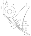
- FIG. 4B is an enlarged perspective view of a region R surrounded by a broken line in FIG. 4A.
- FIG. 3 is an enlarged perspective view of a main part of the peeling unit of the printer of FIG. 2 and its surroundings.
- FIG. 1A It is a schematic block diagram of the printer at the time of normal issue of FIG. 1A. It is a schematic block diagram of the printer at the time of peeling issuing of FIG. 1B. It is a schematic block diagram of the printer of a printing process. It is a principal part expansion schematic block diagram of the printer of FIG. It is a schematic block diagram of the printer of the printing process following FIG. It is a schematic block diagram of the printer of the printing process following FIG. 9A. It is a schematic block diagram of the printer of a back feed process. It is a principal part expansion schematic block diagram of the printer of FIG.
- the present invention relates to the patent application of Japanese Patent Application No. 2014-142097 filed with the Japan Patent Office on July 10, 2014, the contents of which are incorporated herein by reference.
- the direction in which the label continuum (an example of a print medium) is conveyed for printing, specifically, the direction in which the label continuum is sent from the paper supply unit to the thermal head is referred to as a print conveyance direction.
- the back feed refers to an operation of printing desired information on a desired label of the label continuum, then feeding the label continuum in the direction opposite to the print transport direction, and returning the subsequent other labels to the print start position.
- Normal issuance means that when a continuous label (label with mount) is used as a continuous label, a plurality of labels are temporarily attached to a long strip of mount at predetermined intervals, the label must not be peeled off from the mount.
- a method of issuing from a printer while being attached to a mount is referred to as a peeling issue, which is a method of releasing a label from the mount and issuing from a printer.
- FIG. 1A is an overall perspective view of the printer according to the present embodiment in a normal issue state.
- FIG. 1B is an overall perspective view of the printer of FIG.
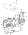
- FIG. 2 is an overall perspective view showing the external appearance of the printer and the label continuum of FIG. 1A when the open / close cover portion is open.
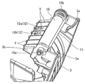
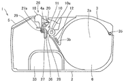
- FIG. 3 is a perspective view of an essential part of the opening / closing cover part of the printer of FIG. 1A.
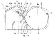
- 4A is a perspective view of a main part of the opening / closing cover part of FIG. 3 as viewed from the opposite surface side (a gear 10b side to be described later).
- 4B is an enlarged perspective view of a region R surrounded by a broken line in FIG. 4A.
- FIG. 5 is an enlarged perspective view of the main part of the peeling unit of the printer of FIG. 2 and its periphery.
- the printer 1 of the present embodiment is a portable label printer formed in a flat rectangular parallelepiped shape, for example, and includes a main body case (housing) 2, an opening / closing cover portion 3, and a peeling A unit (peeling mechanism part) 4 and a front cover part 5 are provided, and a single-unit configuration that can switch between normal issue and peel issue is provided.
- the printer 1 can be used with the issue port side facing up (sideways), but a belt hook (not shown) provided on the bottom surface of the printer 1 is used as an operator's belt. It can also be used in a state in which the issue port side is directed sideways (vertically placed) by hooking or by attaching a shoulder belt (not shown) to the shoulder of the operator.
- the main body case 2 is a casing that forms a part of the outer shape of the printer 1, and an opening 2a is formed on one surface thereof as shown in FIG.
- a paper storage portion (print medium storage portion) 6 is provided in the opening 2a.
- the sheet storage unit 6 is an area for storing the roll-shaped label continuum P, and a pair of guide plates 7a of the sheet guide mechanism unit 7 is installed therein.
- the paper guide mechanism unit 7 is a mechanism unit that supports and guides the label continuous body P according to its width. Note that, as shown in FIGS. 1A and 2, the battery cover portion 8 is pivotally supported on one side surface of the main body case 2 in a state where the battery cover portion 8 can be opened and closed.
- the battery cover portion 8 is an open / close cover for a battery housing portion (not shown in FIGS. 1A to 5) which will be described later.
- the label continuous body P is, for example, a continuous label having a pressure-sensitive adhesive layer on one side (a label without a mount), and is accommodated in the paper accommodating portion 6 while being wound in a roll shape. Is done.
- position detection marks (not shown) that indicate the position of the label are formed at predetermined intervals along the longitudinal direction.
- a thermosensitive coloring layer that develops a specific color (black, red, etc.) when reaching a predetermined temperature range. Is formed.
- the open / close cover portion 3 is an open / close cover for the paper storage portion 6, and is movable in a direction in which one end portion in the longitudinal direction of the open / close cover portion 3 (the longitudinal center side of the main body case 2) is separated from and close to the main body case 2. As described above, the other end portion in the longitudinal direction of the opening / closing cover portion 3 is pivotally supported by one end portion in the longitudinal direction of the main body case 2 by a hinge or the like.
- the open / close cover 3 is opened by a torsion spring (not shown in FIGS. 1A to 3) disposed on the other end in the longitudinal direction (the longitudinal end of the open / close cover 3 is connected to the main body case 2). In a direction away from the head).
- a pair of unit pressing portions 3a and 3a are formed at one end portion in the longitudinal direction of the opening / closing cover portion 3.
- the pair of unit pressing portions 3a, 3a are portions that hold the peeling unit 4 so as to be fixed at the peeling issuing position when the opening / closing cover portion 3 is closed at the time of peeling issuance. It is formed on both ends of the cover portion 3 in the direction orthogonal to the longitudinal direction.
- a platen roller (an example of a conveying roller) 10 is pivotally supported at one end portion in the longitudinal direction of the opening / closing cover portion 3 so as to be rotatable in the forward and reverse directions.
- the platen roller 10 is a conveying unit that conveys the label continuous body P, and is installed in a state of extending along the width direction of the label continuous body P.
- the platen roller 10 is made of, for example, a non-adhesive material such as a resin containing silicone or silicone rubber so that the adhesive of the label continuum P does not stick.
- a gear 10b is connected to one end of the platen shaft 10a of the platen roller 10.
- the gear 10b is engaged with a gear or the like (not shown) installed in the opening 2a when the opening / closing cover 3 is closed, and mechanically connected to a stepping motor (not shown) for driving the roller via the gear or the like. To be connected to.
- a peeling pin 11 is installed along the platen roller 10 in the vicinity of the platen roller 10 at one end in the longitudinal direction of the opening / closing cover 3.
- the peeling pin 11 is a peeling member that peels the label from the mount when a label with a mount is used as the label continuum, and both ends in the longitudinal direction are pivotally supported by the open / close cover portion 3.
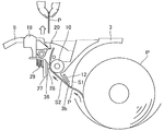
- an open end of the opening / closing cover portion 3 is formed with a head 3b having a V-shaped cross section whose thickness gradually decreases toward the tip.
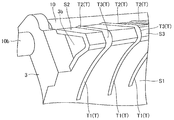
- the head 3b has a first surface S1, a second surface S2, and a third surface (an example of an end portion of the head) S3.
- the first surface S1, the second surface S2, and the third surface S3 may be covered with a non-adhesive material so that the first surface S1, the second surface S2, and the third surface S3 do not easily stick even if the adhesive surface of the label continuum P contacts.
- the first surface S1 is an inner wall surface facing the paper storage unit 6 (that is, the outer periphery of the roll-shaped label continuous body P), and is formed in a curved shape in accordance with the outer periphery of the roll-shaped label continuous body P, for example. Has been.
- the second surface S2 is an inner wall surface facing the adhesive layer of the label continuum P that is fed in a sheet form from the sheet storage unit 6 toward the platen roller 10, and intersects the first surface S1. Is provided.
- the second surface S2 faces the sheet passing route (conveyance path) of the sheet-like label continuous body P, and is formed in a flat shape along the sheet-like label continuous body P.
- the third surface S3 corresponds to the tip of the head 3b of the opening / closing cover portion 3 (the end located near the intersection of the first surface S1 and the second surface S2), and the first surface S1 and the second surface S2 This is a part of the inner wall surface sandwiched between the surface S2.
- the third surface S3 is formed in a flat shape, for example. However, the shape of the third surface S3 is not limited to a flat surface and may be a curved surface.
- Protruding portions T that extend in a continuous manner along the axial direction (longitudinal direction) of platen roller 10 are determined in advance. It is provided at every interval.
- the first protrusion T1 is a part protruding from the first surface S1.
- the second protrusion T2 is a part protruding from the second surface S2.
- the area which the adhesive layer of the sheet-like label continuous body P contacts 2nd surface S2 can be reduced. For this reason, it is possible to suppress or prevent the label continuum P from sticking to the second surface S2.
- 3rd protrusion T3 is a part which protrudes from 3rd surface S3 which is a front-end
- the protrusion length (protrusion height) of the third protrusion T3 is longer than the protrusion lengths of the first protrusion T1 and the second protrusion T2.
- the label continuum P has two contact points (two locations) between the third protrusion T3 and the platen roller 10 between the third surface S3 and the platen roller 10 when the label continuum P is printed and conveyed. It has come to be supported.
- the protrusion length of the second protrusion T2 of the second surface S2 is set to be as long as that of the third protrusion T3. Can be considered.
- the protruding length of the second protrusion T2 is increased, the adhesive surface of the label continuous body P becomes a part of the second protrusion T2 of the second surface S2 when the label continuous body P is conveyed. Increased risk of contact.
- the label continuum P bends between the platen roller 10 and the third surface S3 as described later with reference to FIG.
- the adhesive of the label continuum P can easily come into contact with the second protrusion T2 of the second surface S2. .
- the contact area between the adhesive of the label continuum P and the second surface S2 will increase. From these viewpoints, in the present embodiment, the second surface S2 of the inner wall surface of the opening / closing cover portion 3 protrudes beyond the third protrusion T3 of the third surface S3 of the inner wall surface of the opening / closing cover portion 3. A short second protrusion T2 was provided.
- the shape of the protrusion T is not limited to the above-described one.
- the shape of the protrusion T may be a dot (island). That is, a plurality of dot-shaped protrusions T may be arranged on the inner wall surface (first surface S1, second surface S2, and third surface S3) of the opening / closing cover portion 3.
- the protrusion length of the third protrusion T3 of the third surface S3 is set to be longer than the protrusion length of the first protrusion T1 of the first surface S1 and the second protrusion T2 of the second surface S2. Lengthen.
- sensors 12 (12a, 12b) are installed on the second surface S2 of the opening / closing cover 3.
- the sensor 12a is, for example, a sensor that detects the position of the label of the label continuum P (the position detection mark), and includes a reflective optical sensor or the like.
- the sensor 12b is, for example, a sensor that detects the presence or absence of the label continuum P, and includes a transmissive optical sensor or the like.
- the label continuous body P is supported by the two contact points between the platen roller 10 and the third protrusion T3 of the third surface S3, and is separated from the second surface S2. Therefore, a sufficient space for detecting the label continuum P can be secured between the sensor 12 and the label continuum P. For this reason, the label continuous body P can be favorably detected by the sensor 12.
- the peeling unit 4 has a function of separating the transport path between the mount and the label by peeling the label from the mount when a label with a mount is used as a label continuum, and the longitudinal end portion of the peeling unit 4 is connected to the printer 1. It is installed in a state where it can be moved to a normal issuance position inside the printer and a peeling issuance position outside the printer 1.
- the peeling unit 4 includes a nip roller 4a, a shaft portion 4b that supports the nip roller 4a in a rotatable state, a pair of support portions 4c and 4c that support the nip roller 4a and the shaft portion 4b, A pair of leaf springs 4da and screws 4e for fixing each leaf spring 4da are provided.
- the nip roller 4a is a member that is disposed so as to face the platen roller 10 at the time of release issuance, and is a member that sandwiches and conveys a mount inserted between the nip roller 4a and the platen roller 10 between the nip roller 4a and the platen roller 10. The nip roller 4a is driven to rotate following the rotation of the platen roller 10.
- the pair of leaf springs 4da, 4da is an elastic structure that urges the nip roller 4a toward the platen roller 10 by the unit pressing portion 3a of the opening / closing cover 3 coming into contact when the opening / closing cover 3 is closed at the time of release. is there.
- Each leaf spring 4da is fixed to one end side in the longitudinal direction of the support portion 4c (the side where the nip roller 4a is present) on the outer side surface of each support portion 4c, 4c, and is curved from there to the other end side in the longitudinal direction. It is in a floating state at the terminal end.
- the front cover portion 5 is fixed to the main body case 2 so as to cover the opposite side of the opening / closing cover portion 3 and the vicinity of both side surfaces of the main body case 2 in the opening 2 a of the main body case 2. Yes.
- the front cover portion 5 includes a display portion 15, operation buttons 16 a and 16 b, a power button 17, a cover open button 18, a pair of release lever portions 19 and 19, and a cutter 20.
- the display unit 15 is a screen that displays operation commands, messages, and the like, and is configured by, for example, an LCD (Liquid Crystal Display).
- the operation buttons 16a and 16b are buttons for operating the operation and setting of the printer 1, and the power button 17 is a button for turning on / off the power of the printer 1.
- the cover open button 18 is a button for opening the opening / closing cover part 3.
- the release lever portions 19 and 19 are members that hold the peeling unit 4 in the normal issue position, and the holding state of the peeling unit 4 can be released by moving them in a direction approaching each other.
- the cutter 20 is a member that cuts the label continuum P after the normal issuance.
- the cutter 20 extends from the end of the front cover 5 opposite to the opening / closing cover 3 toward the end of the platen roller 10 of the printer 1 in the axial direction. It is installed in a state where it is extended and formed. An issue port is formed between the opening / closing cover part 3 and the front cover part 5.
- FIG. 6A is a schematic configuration diagram of the printer at the time of normal issuance in FIG. 1A.
- FIG. 6B is a schematic configuration diagram of the printer at the time of release issuance in FIG. 1B.
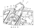
- the printing main body 26 is installed in the opening 2 a of the main body case 2 (inside the main body case 2) in a state adjacent to the paper storage portion 6.
- the printing main body 26 is a functional unit for printing on the label continuum P, and includes a head bracket 27, a thermal head (an example of a printing head unit) 28, a coil spring 29, a peeling unit 4, and a battery housing unit. 33.
- the head bracket 27 is a member that holds the open / close cover portion 3 in a closed state, and is installed in a swingable manner on the opposite side of the platen roller 10 when the open / close cover portion 3 is closed.
- the opening / closing cover portion 3 is held by the head bracket 27 by fitting the platen shaft 10 a of the platen roller 10 into a groove formed in the head bracket 27.
- a pressing portion 27 a is integrally formed with the head bracket 27.
- the pressing portion 27a is arranged at a position (directly below) facing the cover open button 18.
- the cover open button 18 When the cover open button 18 is pressed, the pressing portion 27a is also pressed, and the holding state of the opening / closing cover portion 3 by the head bracket 27 is released. It has come to be.
- the opening / closing cover 3 When the holding state of the opening / closing cover 3 is released, the opening / closing cover 3 is automatically opened by the urging force of the torsion spring 35 disposed on the other end in the longitudinal direction.
- the thermal head 28 is a printing unit that prints information such as characters, symbols, figures, or barcodes on the label continuum P.
- the thermal head 28 faces the platen roller 10 when the opening / closing cover unit 3 is closed.
- 28 is mounted on the head bracket 27 via the circuit board 36 with the print surface 28 facing the paper route.
- a plurality of heating resistors (heating elements) that generate heat when energized are arranged side by side along the width direction of the label continuum P.
- the circuit board 36 is a wiring board that transmits a print signal to the thermal head 28.
- the coil spring 29 is a member that urges the head bracket 27 and the thermal head 28 toward the platen roller 10 when the open / close cover portion 3 is closed, and is installed on the back side of the head bracket 27 (the back side of the mounting surface of the circuit board 36). ing. Since the head bracket 27 is pushed toward the platen roller 10 by the urging force of the coil spring 29, the platen shaft 10a fitted in the groove of the head bracket 27 is also pushed, and the holding state of the opening / closing cover portion 3 by the head bracket 27 is maintained. Has been.
- the battery accommodating portion 33 is a component that accommodates a battery for driving the printer 1 and can be opened and closed by the battery cover portion 8 (see FIG. 2).
- a battery for example, a lithium ion battery is used.
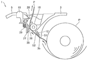
- FIG. 7 is a schematic configuration diagram of the printer in the printing process.
- FIG. 8 is an enlarged schematic configuration diagram of a main part of the printer of FIG.
- FIG. 9A is a schematic configuration diagram of the printer in the printing process subsequent to FIG.
- FIG. 9B is a schematic configuration diagram of the printer in the printing process subsequent to FIG. 9A.
- FIG. 10 is a schematic configuration diagram of the printer in the backfeed process.
- FIG. 11 is an enlarged schematic configuration diagram of a main part of the printer of FIG.
- the platen roller 10 is moved in a state where the label continuous body P fed out in a sheet form from the paper storage unit 6 is sandwiched between the thermal head 28 and the platen roller 10.
- the label continuous body P is conveyed by rotating.
- the printing timing is determined based on the timing signal detected by the sensor 12, and the thermal label of the label continuum P is detected by the heating scanning of the heating resistor of the thermal head 28 by the printing signal transmitted to the thermal head 28. Desired information is printed.
- the peeling unit 4 is disposed inside the printer 1 (below the cutter 20).
- the adhesive layer of the sheet-like label continuum P is the third.
- the area in contact with the surface S3 can be reduced. Therefore, since the frictional resistance at the time of printing conveyance of the sheet-like label continuum P can be reduced, the conveyance of the sheet-like label continuum P is not affected. Since power for conveyance can be reduced, battery consumption of the printer 1 can be reduced.
- the protruding length (projecting height) of the third protrusion T3 is longer (higher) than the protruding lengths of the first protrusion T1 and the second protrusion T2
- printing of the label continuum P is performed.
- the label continuous body P is supported between the third surface S3 and the platen roller 10 at two contact points (two portions) between the third protrusion T3 and the platen roller 10.
- the label continuum P is supported by two contact points (two portions) between the platen roller 10 and the third projection T3 and is separated from the second surface S2, the sensor 12 and the label continuum P
- a sufficient interval can be secured for detecting the label continuum P. For this reason, various information such as the position detection mark of the label continuum P and the presence or absence of the label continuum P can be satisfactorily detected by the sensor 12.
- the protrusion length of the second protrusion T2 of the second surface S2 in the protrusion T is shorter than the protrusion length of the third protrusion T3 of the third surface S3.
- the label portion after printing of the label continuum P is discharged, the label portion is picked with a finger and separated using the edge of the cutter 20 as shown in FIG. 9B.
- the label continuous body P is back-fed to return the subsequent label portion of the label continuous body P to the print position (thermal head 28 side).
- the label continuum P bends between the platen roller 10 and the third surface S3, and approaches the second surface S2.
- the protrusion length of the second protrusion T2 is as long as the third protrusion T3, the adhesive of the label continuum P easily comes into contact with the second protrusion T2.
- the protrusion length of the second protrusion T2 is shorter (lower) than the protrusion length of the third protrusion T3. It is difficult for the agent layer to contact the second protrusion T2. Even if contact is made, the contact area is small and does not stick. For this reason, the conveyance property at the time of the back feed of the label continuous body P can also be improved.
- the present invention is not limited to this, and a printer that can be used only for normal issue. It can also be applied to.
- the continuous label (label without a mount) which has an adhesive layer on one side was used as a printing medium was demonstrated, it is not limited to this,
- multiple Label continuous body (label with mount) temporarily attached to a long strip of mount, continuous sheet without adhesive layer (continuous sheet), or film that can be printed by thermal heads, not limited to paper, etc.
- thermal heads not limited to paper, etc.
- a label with a mount, a continuous sheet or a film can be provided with a position detection mark.
Abstract
Description
本発明の第2態様のプリンタは、前記頭部は、前記開閉カバー部の閉止時に前記印字媒体収容部に向いた第1の面と、前記印字媒体収容部から前記搬送ローラに向けて搬送される印字媒体の粘着剤層に向いた第2の面と、を有し、前記端部は、前記第1の面と第2の面との交線近傍に位置し、前記第2の面から突部が突出し、前記端部から突出する突部の突出長は、前記印字媒体が前記端部から突出する突部に接した場合に、前記端部から突出する突部と前記搬送ローラとで印字媒体を支持するように、前記第2の面から突出する突部の突出長よりも長く形成されていることを特徴とする。
本発明の第3態様のプリンタでは、前記開閉カバー部の前記第1の面には、前記端部から突出する突部よりも突出長の短い突部が設けられていてもよい。
本発明の第4態様のプリンタでは、前記第2の面には、前記印字媒体を検出するセンサが設けられていてもよい。 The printer according to the first aspect of the present invention includes a housing in which an opening is formed, and a printing medium storage portion that is provided in the opening of the housing and can store a printing medium having an adhesive layer on one side. And an open / close cover portion that opens and closes the print medium accommodating portion, a conveyance roller that conveys the print medium, and a print that is provided to face the conveyance roller and that prints on the print medium. A head portion having a thickness that gradually decreases toward the tip thereof, and the head portion includes a protrusion protruding from the end portion of the head portion. It is characterized by having.
In the printer according to the second aspect of the present invention, the head is transported from the first surface facing the print medium housing portion when the opening / closing cover portion is closed, and from the print medium housing portion toward the transport roller. A second surface facing the pressure-sensitive adhesive layer of the printing medium, and the end is located in the vicinity of the line of intersection between the first surface and the second surface, from the second surface The protruding length of the protruding portion protruding from the end portion is determined by the protruding portion protruding from the end portion and the conveying roller when the print medium is in contact with the protruding portion protruding from the end portion. It is characterized by being formed longer than the protruding length of the protrusion protruding from the second surface so as to support the print medium.
In the printer according to the third aspect of the present invention, the first surface of the opening / closing cover portion may be provided with a protrusion having a protrusion length shorter than the protrusion protruding from the end portion.
In the printer according to the fourth aspect of the present invention, a sensor for detecting the print medium may be provided on the second surface.
また、用紙収容部内の印字媒体と第1の面との接触面積を低減することができるので、用紙収容部内の印字媒体が回転するときの摩擦抵抗を低減することが可能になる。
また、印字媒体とセンサとの間に、印字媒体を検出する上で充分な間隔を確保することができるので、印字媒体をセンサにより良好に検出することが可能になる。 According to the present invention, it is possible to reduce the contact area between the pressure-sensitive adhesive layer of the print medium and the member of the conveyance path of the print medium, so that it is possible to improve the conveyance of the print medium in the printer.
In addition, since the contact area between the print medium in the paper storage portion and the first surface can be reduced, it is possible to reduce the frictional resistance when the print medium in the paper storage portion rotates.
In addition, since a sufficient interval can be secured between the print medium and the sensor to detect the print medium, it is possible to detect the print medium satisfactorily by the sensor.
Claims (4)
- 開口部が形成された筐体と、
前記筐体の開口部内に設けられ、片面に粘着剤層を有する印字媒体を収容することが可能な印字媒体収容部と、
前記筐体に設けられ、前記印字媒体収容部を開閉する開閉カバー部と、
前記印字媒体を搬送する搬送ローラと、
前記搬送ローラに対向するように設けられ、印字媒体に印字を施す印字ヘッド部と、
を備え、
前記開閉カバー部の開放端には先端に向かって厚さが漸減する頭部が形成されるとともに、前記頭部は、前記頭部の端部から突出する突部を有することを特徴とするプリンタ。 A housing in which an opening is formed;
A print medium housing portion provided in the opening of the housing and capable of housing a print medium having an adhesive layer on one side;
An opening / closing cover portion provided on the housing for opening and closing the print medium accommodating portion;
A transport roller for transporting the print medium;
A print head provided to face the transport roller and for printing on a print medium;
With
A head having a thickness gradually decreasing toward the tip is formed at an open end of the opening / closing cover, and the head has a protrusion protruding from an end of the head. . - 前記頭部は、
前記開閉カバー部の閉止時に前記印字媒体収容部に向いた第1の面と、
前記印字媒体収容部から前記搬送ローラに向けて搬送される印字媒体の粘着剤層に向いた第2の面と、を有し、
前記端部は、前記第1の面と第2の面との交線近傍に位置し、
前記第2の面から突部が突出し、
前記端部から突出する突部の突出長は、前記印字媒体が前記端部から突出する突部に接した場合に、前記端部から突出する突部と前記搬送ローラとで印字媒体を支持するように、前記第2の面から突出する突部の突出長よりも長く形成されていることを特徴とする請求項1に記載のプリンタ。 The head is
A first surface facing the print medium accommodating portion when the opening / closing cover portion is closed;
A second surface facing the adhesive layer of the print medium conveyed from the print medium accommodating unit toward the conveyance roller,
The end is located in the vicinity of the intersection line of the first surface and the second surface,
A protrusion protrudes from the second surface;
The protrusion length of the protrusion protruding from the end portion supports the print medium by the protrusion protruding from the end portion and the transport roller when the print medium contacts the protrusion protruding from the end portion. The printer according to claim 1, wherein the printer is formed longer than a protruding length of the protruding portion protruding from the second surface. - 前記開閉カバー部の前記第1の面には、前記端部から突出する突部よりも突出長の短い突部が設けられていることを特徴とする請求項2記載のプリンタ。 3. The printer according to claim 2, wherein the first surface of the opening / closing cover portion is provided with a protrusion having a protrusion length shorter than a protrusion protruding from the end portion.
- 前記第2の面には、前記印字媒体を検出するセンサが設けられていることを特徴とする請求項2又は3記載のプリンタ。 4. The printer according to claim 2, wherein a sensor for detecting the print medium is provided on the second surface.
Priority Applications (4)
| Application Number | Priority Date | Filing Date | Title |
|---|---|---|---|
| US15/310,273 US9862205B2 (en) | 2014-07-10 | 2015-04-08 | Printer |
| CN201580024121.2A CN106457850B (en) | 2014-07-10 | 2015-04-08 | Printer |
| EP15819395.3A EP3168050B1 (en) | 2014-07-10 | 2015-04-08 | Printer |
| KR1020167030712A KR101876821B1 (en) | 2014-07-10 | 2015-04-08 | Printer |
Applications Claiming Priority (2)
| Application Number | Priority Date | Filing Date | Title |
|---|---|---|---|
| JP2014-142097 | 2014-07-10 | ||
| JP2014142097A JP5897656B2 (en) | 2014-07-10 | 2014-07-10 | Printer |
Publications (1)
| Publication Number | Publication Date |
|---|---|
| WO2016006291A1 true WO2016006291A1 (en) | 2016-01-14 |
Family
ID=55063936
Family Applications (1)
| Application Number | Title | Priority Date | Filing Date |
|---|---|---|---|
| PCT/JP2015/060944 WO2016006291A1 (en) | 2014-07-10 | 2015-04-08 | Printer |
Country Status (6)
| Country | Link |
|---|---|
| US (1) | US9862205B2 (en) |
| EP (1) | EP3168050B1 (en) |
| JP (1) | JP5897656B2 (en) |
| KR (1) | KR101876821B1 (en) |
| CN (1) | CN106457850B (en) |
| WO (1) | WO2016006291A1 (en) |
Cited By (2)
| Publication number | Priority date | Publication date | Assignee | Title |
|---|---|---|---|---|
| USD893590S1 (en) * | 2018-02-09 | 2020-08-18 | Toshiba Tec Kabushiki Kaisha | Printer |
| USD963038S1 (en) * | 2015-07-17 | 2022-09-06 | Zebra Technologies Corporation | Media processing device |
Families Citing this family (6)
| Publication number | Priority date | Publication date | Assignee | Title |
|---|---|---|---|---|
| US20070001383A1 (en) | 2005-06-20 | 2007-01-04 | Gregory Jantsch | Dispensing of currency |
| JP5897656B2 (en) | 2014-07-10 | 2016-03-30 | サトーホールディングス株式会社 | Printer |
| JP6904771B2 (en) * | 2017-04-26 | 2021-07-21 | セイコーインスツル株式会社 | Thermal printers and portable terminals |
| KR101970512B1 (en) * | 2017-08-08 | 2019-04-22 | 제이스테판 주식회사 | Portable printer |
| JP2022183739A (en) * | 2021-05-31 | 2022-12-13 | セイコーエプソン株式会社 | printer |
| JP2023002368A (en) * | 2021-06-22 | 2023-01-10 | セイコーエプソン株式会社 | printer |
Citations (4)
| Publication number | Priority date | Publication date | Assignee | Title |
|---|---|---|---|---|
| JPH09254473A (en) * | 1996-03-22 | 1997-09-30 | Kofu Nippon Denki Kk | Roll paper storage device for printer |
| JP2004188935A (en) * | 2002-12-13 | 2004-07-08 | Canon Semiconductor Equipment Inc | Printer and method of controlling the same |
| JP2006026931A (en) * | 2004-07-12 | 2006-02-02 | Brother Ind Ltd | Printing device |
| JP2012240202A (en) * | 2011-05-13 | 2012-12-10 | Max Co Ltd | Label printer |
Family Cites Families (11)
| Publication number | Priority date | Publication date | Assignee | Title |
|---|---|---|---|---|
| DE60002145T2 (en) * | 1999-12-15 | 2003-12-18 | Seiko Epson Corp | printer |
| US6609844B1 (en) * | 2001-11-09 | 2003-08-26 | Zih Corp. | Portable printer having automatic print alignment |
| JP4639173B2 (en) | 2006-09-11 | 2011-02-23 | 株式会社サトー | Printer |
| US20080095565A1 (en) * | 2006-10-23 | 2008-04-24 | Zih Corp. | Printer With Platen Support Device for Linerless Media and Associated Method |
| JP2009107287A (en) * | 2007-10-31 | 2009-05-21 | Fujitsu Isotec Ltd | Printing device |
| JP5351648B2 (en) * | 2009-07-30 | 2013-11-27 | サトーホールディングス株式会社 | Mount prevention device for non-mounting label in thermal printer |
| US8752922B2 (en) * | 2010-04-12 | 2014-06-17 | Zih Corp. | Mobile printer networking and interfacing |
| US9434191B2 (en) * | 2010-04-12 | 2016-09-06 | Zih Corp. | Label peeling, universal printheads and related methods |
| JP5074555B2 (en) * | 2010-06-02 | 2012-11-14 | 東芝テック株式会社 | Printer |
| CN103847226B (en) * | 2012-11-29 | 2016-08-17 | 兄弟工业株式会社 | Printer |
| JP5897656B2 (en) | 2014-07-10 | 2016-03-30 | サトーホールディングス株式会社 | Printer |
-
2014
- 2014-07-10 JP JP2014142097A patent/JP5897656B2/en active Active
-
2015
- 2015-04-08 US US15/310,273 patent/US9862205B2/en active Active
- 2015-04-08 WO PCT/JP2015/060944 patent/WO2016006291A1/en active Application Filing
- 2015-04-08 KR KR1020167030712A patent/KR101876821B1/en active IP Right Grant
- 2015-04-08 EP EP15819395.3A patent/EP3168050B1/en active Active
- 2015-04-08 CN CN201580024121.2A patent/CN106457850B/en active Active
Patent Citations (4)
| Publication number | Priority date | Publication date | Assignee | Title |
|---|---|---|---|---|
| JPH09254473A (en) * | 1996-03-22 | 1997-09-30 | Kofu Nippon Denki Kk | Roll paper storage device for printer |
| JP2004188935A (en) * | 2002-12-13 | 2004-07-08 | Canon Semiconductor Equipment Inc | Printer and method of controlling the same |
| JP2006026931A (en) * | 2004-07-12 | 2006-02-02 | Brother Ind Ltd | Printing device |
| JP2012240202A (en) * | 2011-05-13 | 2012-12-10 | Max Co Ltd | Label printer |
Cited By (2)
| Publication number | Priority date | Publication date | Assignee | Title |
|---|---|---|---|---|
| USD963038S1 (en) * | 2015-07-17 | 2022-09-06 | Zebra Technologies Corporation | Media processing device |
| USD893590S1 (en) * | 2018-02-09 | 2020-08-18 | Toshiba Tec Kabushiki Kaisha | Printer |
Also Published As
| Publication number | Publication date |
|---|---|
| KR101876821B1 (en) | 2018-07-10 |
| US20170266996A1 (en) | 2017-09-21 |
| EP3168050A1 (en) | 2017-05-17 |
| CN106457850B (en) | 2018-10-02 |
| JP5897656B2 (en) | 2016-03-30 |
| US9862205B2 (en) | 2018-01-09 |
| JP2016016620A (en) | 2016-02-01 |
| EP3168050A4 (en) | 2018-02-28 |
| EP3168050B1 (en) | 2020-03-25 |
| CN106457850A (en) | 2017-02-22 |
| KR20160140910A (en) | 2016-12-07 |
Similar Documents
| Publication | Publication Date | Title |
|---|---|---|
| JP5897656B2 (en) | Printer | |
| JP5850977B2 (en) | Printer | |
| JP5852715B1 (en) | Printer | |
| JP5823011B1 (en) | Printer | |
| EP3141395B1 (en) | Printer | |
| JP2016137684A (en) | Printer | |
| JP6282530B2 (en) | Printer | |
| JP6301183B2 (en) | Printer | |
| WO2015198681A1 (en) | Label printer | |
| JP6358759B2 (en) | Printer | |
| JP6121510B2 (en) | Printer | |
| JP6262032B2 (en) | Printer | |
| JP2016022711A (en) | Printer | |
| JP6505984B2 (en) | Printer | |
| JP6633718B2 (en) | Printer | |
| JP6257452B2 (en) | Printer | |
| JP6494256B2 (en) | Label printer | |
| JP6862528B2 (en) | Printer | |
| JP6110526B2 (en) | Printer | |
| JP6470782B2 (en) | Printer | |
| JP6257487B2 (en) | Printer |
Legal Events
| Date | Code | Title | Description |
|---|---|---|---|
| 121 | Ep: the epo has been informed by wipo that ep was designated in this application |
Ref document number: 15819395 Country of ref document: EP Kind code of ref document: A1 |
|
| ENP | Entry into the national phase |
Ref document number: 20167030712 Country of ref document: KR Kind code of ref document: A |
|
| REEP | Request for entry into the european phase |
Ref document number: 2015819395 Country of ref document: EP |
|
| WWE | Wipo information: entry into national phase |
Ref document number: 2015819395 Country of ref document: EP |
|
| WWE | Wipo information: entry into national phase |
Ref document number: 15310273 Country of ref document: US |
|
| NENP | Non-entry into the national phase |
Ref country code: DE |