WO2016006197A1 - Method of manufacturing a lithium-ion secondary battery electrode sheet based on an active material dry powder - Google Patents
Method of manufacturing a lithium-ion secondary battery electrode sheet based on an active material dry powder Download PDFInfo
- Publication number
- WO2016006197A1 WO2016006197A1 PCT/JP2015/003264 JP2015003264W WO2016006197A1 WO 2016006197 A1 WO2016006197 A1 WO 2016006197A1 JP 2015003264 W JP2015003264 W JP 2015003264W WO 2016006197 A1 WO2016006197 A1 WO 2016006197A1
- Authority
- WO
- WIPO (PCT)
- Prior art keywords
- current collector
- granulated particles
- powder material
- binder
- particles
- Prior art date
- Legal status (The legal status is an assumption and is not a legal conclusion. Google has not performed a legal analysis and makes no representation as to the accuracy of the status listed.)
- Ceased
Links
Images


Classifications
-
- H—ELECTRICITY
- H01—ELECTRIC ELEMENTS
- H01M—PROCESSES OR MEANS, e.g. BATTERIES, FOR THE DIRECT CONVERSION OF CHEMICAL ENERGY INTO ELECTRICAL ENERGY
- H01M4/00—Electrodes
- H01M4/02—Electrodes composed of, or comprising, active material
- H01M4/04—Processes of manufacture in general
- H01M4/0402—Methods of deposition of the material
- H01M4/0404—Methods of deposition of the material by coating on electrode collectors
-
- H—ELECTRICITY
- H01—ELECTRIC ELEMENTS
- H01M—PROCESSES OR MEANS, e.g. BATTERIES, FOR THE DIRECT CONVERSION OF CHEMICAL ENERGY INTO ELECTRICAL ENERGY
- H01M10/00—Secondary cells; Manufacture thereof
- H01M10/05—Accumulators with non-aqueous electrolyte
- H01M10/052—Li-accumulators
- H01M10/0525—Rocking-chair batteries, i.e. batteries with lithium insertion or intercalation in both electrodes; Lithium-ion batteries
-
- H—ELECTRICITY
- H01—ELECTRIC ELEMENTS
- H01M—PROCESSES OR MEANS, e.g. BATTERIES, FOR THE DIRECT CONVERSION OF CHEMICAL ENERGY INTO ELECTRICAL ENERGY
- H01M4/00—Electrodes
- H01M4/02—Electrodes composed of, or comprising, active material
- H01M4/04—Processes of manufacture in general
- H01M4/043—Processes of manufacture in general involving compressing or compaction
- H01M4/0435—Rolling or calendering
-
- H—ELECTRICITY
- H01—ELECTRIC ELEMENTS
- H01M—PROCESSES OR MEANS, e.g. BATTERIES, FOR THE DIRECT CONVERSION OF CHEMICAL ENERGY INTO ELECTRICAL ENERGY
- H01M4/00—Electrodes
- H01M4/02—Electrodes composed of, or comprising, active material
- H01M4/13—Electrodes for accumulators with non-aqueous electrolyte, e.g. for lithium-accumulators; Processes of manufacture thereof
- H01M4/139—Processes of manufacture
-
- B—PERFORMING OPERATIONS; TRANSPORTING
- B05—SPRAYING OR ATOMISING IN GENERAL; APPLYING FLUENT MATERIALS TO SURFACES, IN GENERAL
- B05D—PROCESSES FOR APPLYING FLUENT MATERIALS TO SURFACES, IN GENERAL
- B05D3/00—Pretreatment of surfaces to which liquids or other fluent materials are to be applied; After-treatment of applied coatings, e.g. intermediate treating of an applied coating preparatory to subsequent applications of liquids or other fluent materials
- B05D3/12—Pretreatment of surfaces to which liquids or other fluent materials are to be applied; After-treatment of applied coatings, e.g. intermediate treating of an applied coating preparatory to subsequent applications of liquids or other fluent materials by mechanical means
-
- B—PERFORMING OPERATIONS; TRANSPORTING
- B05—SPRAYING OR ATOMISING IN GENERAL; APPLYING FLUENT MATERIALS TO SURFACES, IN GENERAL
- B05D—PROCESSES FOR APPLYING FLUENT MATERIALS TO SURFACES, IN GENERAL
- B05D5/00—Processes for applying liquids or other fluent materials to surfaces to obtain special surface effects, finishes or structures
- B05D5/12—Processes for applying liquids or other fluent materials to surfaces to obtain special surface effects, finishes or structures to obtain a coating with specific electrical properties
-
- Y—GENERAL TAGGING OF NEW TECHNOLOGICAL DEVELOPMENTS; GENERAL TAGGING OF CROSS-SECTIONAL TECHNOLOGIES SPANNING OVER SEVERAL SECTIONS OF THE IPC; TECHNICAL SUBJECTS COVERED BY FORMER USPC CROSS-REFERENCE ART COLLECTIONS [XRACs] AND DIGESTS
- Y02—TECHNOLOGIES OR APPLICATIONS FOR MITIGATION OR ADAPTATION AGAINST CLIMATE CHANGE
- Y02E—REDUCTION OF GREENHOUSE GAS [GHG] EMISSIONS, RELATED TO ENERGY GENERATION, TRANSMISSION OR DISTRIBUTION
- Y02E60/00—Enabling technologies; Technologies with a potential or indirect contribution to GHG emissions mitigation
- Y02E60/10—Energy storage using batteries
-
- Y—GENERAL TAGGING OF NEW TECHNOLOGICAL DEVELOPMENTS; GENERAL TAGGING OF CROSS-SECTIONAL TECHNOLOGIES SPANNING OVER SEVERAL SECTIONS OF THE IPC; TECHNICAL SUBJECTS COVERED BY FORMER USPC CROSS-REFERENCE ART COLLECTIONS [XRACs] AND DIGESTS
- Y02—TECHNOLOGIES OR APPLICATIONS FOR MITIGATION OR ADAPTATION AGAINST CLIMATE CHANGE
- Y02P—CLIMATE CHANGE MITIGATION TECHNOLOGIES IN THE PRODUCTION OR PROCESSING OF GOODS
- Y02P70/00—Climate change mitigation technologies in the production process for final industrial or consumer products
- Y02P70/50—Manufacturing or production processes characterised by the final manufactured product
Definitions
- the present invention relates to a method of manufacturing a lithium-ion secondary battery electrode sheet.
- the present application claims priority from Japanese Patent Application No. 2014-143142, filed on July 11, 2014, the entirety of which is incorporated by reference into this specification.
- the term “secondary battery” refers to a repeatedly rechargeable battery in general.
- the term “lithium-ion secondary battery” means a secondary battery that uses lithium ions as the electrolyte ions and implements charging and discharging by the transfer of electric charge which is associated with the transfer of the lithium ions between the positive and negative electrodes.
- the lithium-ion secondary battery is one type of non-aqueous electrolyte secondary battery, which uses a non-aqueous electrolyte comprising a non-aqueous solvent in which an electrolyte salt is dissolved.
- JP 2013-012327 A discloses that an electrode sheet is manufactured by coating a binder solution on an electrode current collector, thereafter depositing powder containing an active material and a binder thereon, and pressing the deposited layer in a thickness direction while heating the deposited layer.
- JP 2013-143304 A discloses a method of manufacturing an electrode sheet by powder molding.
- the publication discloses that an electrode sheet is formed by granulating an electrode mixture containing graphite while applying a magnetic field thereto to obtain an electrode mixture powder, then feeding the resultant powder onto the current collector foil, and then pressing the current collector foil.
- JP 2013-134897 A discloses the following.
- a hot melt binder aqueous solution in a liquid state is applied onto the surface of a sheet-shaped current collector and dried, and granulated particles containing active material particles and a binder are fed onto the surface of the current collector. Then, the current collector, the hot melt binder layer, and the granulated particles are compressed in a thickness direction of the current collector, while being heated.
- an electrode sheet having an active material layer formed on a current collector is manufactured by depositing powder of granulated particles containing an active material and a binder on a current collector and compressing the deposited powder and the current collector in a thickness direction.
- there is another method of manufacturing an electrode sheet The method involves coating a current collector with a mixture paste containing an active material and a binder mixed with a solvent, and drying the paste, to form an active material layer.
- the method of coating a current collector with a mixture paste and drying the paste to form an active material layer is introduced as prior art in, for example, JP 2013-134897 A.
- the peel strength of the active material layer tends to be lower in the case where the active material layer is formed by depositing powder of granulated particles than in the case where the active material layer is formed by coating the current collector with a mixture paste and drying the paste.
- the present inventors believe the cause of this tendency to be that pressing the granulated particles against the current collector foil provides only a small contact area of the binder in the case where the active material layer is formed by depositing powder of granulated particles.
- the binder component contained in the paste is dried and solidified in such a condition that the binder component is adhered extensively to the surfaces of the active material particles, which are also contained in the paste.
- the contact area of the binder is large in this case because the binder is dried in such a condition that it is adhered extensively to the active material particles and the current collector foil according to the surface tension of the paste.
- the method of forming the active material layer by coating the current collector with a mixture paste and drying the paste tends to produce an active material layer having a higher peel strength than the method of forming the active material layer from the powder material of granulated particles.
- the method of forming the active material layer by depositing powder of granulated particles does not have the drying step. This provides an advantage that the manufacturing cost can be lowered than the method of forming the active material layer by coating the current collector with a mixture paste and drying the paste.
- the present inventors believe that it is desirable to adopt the method of forming the active material layer by depositing powder of granulated particles on the current collector and pressing the current collector provided with the powder of granulated particles in order to keep the manufacturing cost low, and improve the peel strength of the obtained active material layer at the same time.
- a method of manufacturing a lithium-ion secondary battery electrode sheet proposed herein includes the following steps of: (a) preparing a current collector; (b) preparing granulated particles containing active material particles and a binder; (c) preparing a binder solution; (d) applying the binder solution onto the current collector; (e) feeding a powder material of the granulated particles onto the current collector; (f) pressing the powder material of the granulated particles against the current collector; and (g) subsequent to the step (e) and prior to or during the step (f), enhancing adhesive strength of the powder material of the granulated particles that has been fed on the current collector.
- the binder contained in the granulated particles and the binder contained in the binder solution may be the same as or different from each other. It should be noted that the order of the steps is not limited to the order of the steps as listed above, unless specifically stated otherwise.
- the method of manufacturing a lithium-ion secondary battery electrode sheet may be such that a solvent is added to the powder material of the granulated particles subsequent to the step (e) and prior to or during the step (f).
- solvent means one that is in a liquid form, and it may be any type of solvent, such as water and an organic solvent, as long as it is in a liquid state.
- examples of the organic solvent include alcohols, ethers, ketones, aromatic hydrocarbons, and chlorinated hydrocarbons.
- the method of manufacturing a lithium-ion secondary battery electrode sheet may comprise imparting shearing stress to the powder material of the granulated particles while pressing the powder material of the granulated particles against the current collector.
- the current collector and the granulated particles may be pressed by a pair of pressure rollers.
- the pair of pressure rollers may be rotated at different rotational speeds.
- an appropriate level of shearing stress can be imparted to the powder material of the granulated particles.
- the rotational speed of the pressure roller to be pressed against the powder material of the granulated particles may be made slower than that of the pressure roller to be pressed against the current collector.
- Fig. 1 is a schematic view illustrating a manufacturing apparatus that embodies a method of manufacturing a lithium-ion secondary battery electrode sheet proposed herein.
- Fig. 2 is a schematic view schematically illustrating a granulated particle.
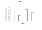
- Fig. 3 is a graph showing peel strength of samples 1 through 4 of a lithium-ion secondary battery electrode sheet.
- Fig. 1 is a schematic view illustrating a manufacturing apparatus 10 that embodies a method of manufacturing a lithium-ion secondary battery electrode sheet proposed herein.
- the manufacturing apparatus 10 has a conveyor device 21 for conveying a current collector 11, a coating device 22 for applying a binder solution 12, a feeding device 23 for feeding a powder material 13 of granulated particles 13a (see Fig. 2), a squeegee 24, a humidifier device 25, and pressure rollers 26 and 27.
- Fig. 2 is a view schematically illustrating the granulated particle 13a.
- a method of manufacturing a lithium-ion secondary battery electrode sheet proposed herein includes the following steps 1 through 7: 1. preparing a current collector 11; 2. preparing granulated particles 13a; 3. preparing a binder solution; 4. applying the binder solution onto the current collector 11; 5. feeding a powder material 13 of the granulated particles 13a onto the current collector 11; 6. pressing the powder material 13 of the granulated particles 13a against the current collector 11; and 7. subsequent to feeding the powder material 13 of the granulated particles and prior to or during pressing the powder material 13 of the granulated particles 13a against the current collector 11, enhancing adhesive strength of the powder material 13 of the granulated particles 13a.
- the current collector 11 is prepared.
- the current collector 11 prepared here is a member for obtaining electricity in the lithium-ion secondary battery electrode sheet.
- the material suitable as the current collector 11 used for a lithium-ion secondary battery is a material that has good electron conductivity and is capable of existing stably within the battery.
- the current collector 11 also requires being lightweight, predetermined mechanical strength, processability, and so forth.
- an aluminum foil is used as the current collector 11 for the positive electrode of a lithium-ion secondary battery.
- a copper foil is used as the current collector 11 for the negative electrode thereof. In the example shown in Fig.
- a strip-shaped metal foil (specifically, an aluminum foil or a copper foil) is prepared as the current collector, and although not shown in the figure, it is prepared in a condition of being coiled around a winding core.
- the strip-shaped current collector foil 11 is conveyed by the conveyor device 21 along a predetermined conveyance passage.
- Such a strip-shaped current collector foil 11 is suitable for subjecting it to a predetermined treatment while it is being conveyed in a roll-to-roll process, as illustrated in Fig. 1.
- the current collector 11 herein is prepared in the form of strip-shaped current collector foil, it may be formed in the form of a sheet-shaped current collector foil having a predetermined shape and may be processed by a sheet-by-sheet system.
- the granulated particles 13a are prepared. It is desirable that the granulated particles 13a prepared here contain at least active material particles 13a1 and a binder 13a2.
- the powder material 13 of the granulated particles 13a can be obtained by, for example, granulating a mixture (suspension) in which the active material particles 13a1 and the binder 13a2 are mixed with a solvent by a spray drying method. In the spray drying method, the mixture is sprayed in a dry atmosphere. At this stage, the particles contained in each of the sprayed droplets are merged into roughly one aggregate and formed into a larger particle. Therefore, depending on the size of the droplets, the solid content contained in the granulated particle 13a can vary, and also, the size, mass, and the like of the granulated particle 13a can vary.
- Such droplets cause migration in the process of being dried.
- the particle of the binder 13a2 contained in the droplet is smaller than the active material particle 13a1, and the density thereof is also lower.
- the binder tends to move toward the surface of the droplet.
- the granulated particle 13a in which the binder 13a2 is biased toward the surface is obtained, as illustrated in Fig. 2.
- the phrase “the binder 13a2 is biased toward the surface” means the condition in which the component of the binder 13a2 is contained in a greater amount in a portion of the granulated particle 13a near the surface than a central portion of the granulated particle 13a.
- the droplets to be sprayed contain at least the active material particles 13a1 and the binder 13a2. It is also possible that the droplets to be sprayed may contain materials other than the active material particles 13a1 and the binder 13a2. For example, a conductive agent may be contained therein.
- the active material particles 13a1 contained in the granulated particles 13a may vary depending on the electrode sheet to be manufactured.
- the active material particles for the positive electrode are used for the active material particles 13a1.
- the active material particles for the negative electrode are used for the active material particles 13a1.
- the lithium-ion secondary battery is taken as an example.
- the active material particles 13a1 used in the positive electrode of the lithium-ion secondary battery include: oxides containing lithium and one or more transition metal elements (i.e., lithium-transition metal oxide), such as lithium nickel oxide (for example, LiNiO 2 ), lithium cobalt oxide (for example, LiCoO 2 ), and lithium manganese oxide (LiMn 2 O 4 ); and phosphates containing lithium and one or more transition metal elements, such as lithium manganese phosphate (LiMnPO 4 ) and lithium iron phosphate (LiFePO 4 ).
- transition metal elements i.e., lithium-transition metal oxide
- LiNiO 2 lithium nickel oxide
- LiCoO 2 lithium cobalt oxide
- LiMn 2 O 4 lithium manganese oxide
- phosphates containing lithium and one or more transition metal elements such as lithium manganese phosphate (LiMnPO 4 ) and lithium iron phosphate (LiF
- positive electrode active material particles are used in particulate form and may be referred to as positive electrode active material particles, as appropriate.
- the positive electrode active material particles may be used either alone or in combination. Because these positive electrode active material particles have low electrical conductivity, the positive electrode active material layer contains a conductive agent in order to enhance the electrical conductivity. In this case, it is desirable that the conductive agent be contained in droplets that are sprayed in spray drying.
- the active material particles used in the negative electrode of the lithium-ion secondary battery include carbon-based materials, such as graphite carbons and amorphous carbons, lithium-transition metal oxides, and lithium-transition metal nitrides. These are used in particulate form and may be referred to as negative electrode active material particles, as appropriate.
- the negative electrode active material particles may be used either alone or in combination.
- the negative electrode active material layer may contain a conductive agent in order to enhance the electrical conductivity. In this case, it is desirable that the conductive agent be contained in droplets that are sprayed in spray drying.
- Examples of the conductive agent include carbon materials, such as carbon powder and carbon fiber. It is possible to use one of the just-mentioned examples of the conductive agents either alone or in combination with another one or more of the examples.
- Examples of the carbon powder include various types of carbon blacks (such as acetylene black, oil-furnace black, graphitized carbon black, and Ketjen Black) and graphite powder. It is desirable to use such a conductive agent for forming conductive paths between the active material particles 13a1 and the current collector 11 when the used active material particles 13a1 have poor electrical conductivity.
- the binder 13a2 that is to be added to the granulated particles 13a in the step of preparing granulated particles 13a.
- the granulated particles 13a are preferably granulated by a spray drying method. For this reason, a polymer that can be dissolved or dispersed in a solvent is used as the binder 13a2 that is to be added to the granulated particles 13a.
- Examples of the polymer that can be dissolved or dispersed in an aqueous solvent include rubber materials (such as styrene-butadiene copolymer (SBR) and acrylic acid-modified SBR resin (SBR latex)), polyvinyl alcohols (PVA), vinyl acetate copolymers, and acrylate polymers.
- Examples of the polymer that can be dissolved or dispersed in a non-aqueous solvent include polymers such as polyvinylidene fluoride (PVDF), polyvinylidene chloride (PVDC), and polyacrylonitrile (PAN).
- PEO polyethylene oxide
- FEP tetrafluoroethylene-hexafluoropropylene copolymer
- the droplets sprayed in the spray drying may contain cellulose-based polymers (such as carboxymethylcellulose (CMC) and hydroxypropyl methyl cellulose (HPMC)) as a thickening agent.
- CMC carboxymethylcellulose
- HPMC hydroxypropyl methyl cellulose
- the binder solution 12 is prepared.
- the binder solution 12 prepared here is a solution in which a binder is mixed with a solvent.
- an aqueous solvent As the solvent for the binder solution 12.
- water or a mixed solvent mainly composed of water is used.
- the solvent of the binder solution 12 is not limited to what is called an aqueous solvent, but may be what is called an organic-based solvent.
- An example of the organic-based solvent is N-methylpyrrolidone (NMP).
- the binder contained in the binder solution 12 be one that can be dispersed in a solvent.
- preferable examples include styrene-butadiene rubber (SBR) and polyacrylic acid (PAA), because the solvent is an aqueous solvent.
- SBR is used as the binder.
- preferable examples of the binder include polyvinylidene fluoride (PVDF) and polyacrylic acid (PAA).
- a preferable example of the binder solution 12 may be a SBR aqueous solution (40 wt %) in which SBR as the binder is contained at a concentration of 40 wt % and water is used as the solvent.
- the binder solution 12 is applied onto the current collector foil 11. It is desirable that the binder solution 12 be applied onto the current collector 11 in a predetermined pattern. It is also desirable that the binder solution 12 be applied thinly onto the current collector 11, for example, at a thickness of from about 1 ⁇ m to 20 ⁇ m, and be applied by gravure printing or the like.
- Fig. 1 shows a direct gravure roll coater as an example of the coating device 22. It is desirable to transfer the binder solution 12 onto the current collector 11 by direct gravure printing using the gravure roller 22a having minute patterns engraved on the surface thereof.
- the gravure roller 22a have, for example, grooves having a print depth of about from 10 ⁇ m to 30 ⁇ m (for example, 20 ⁇ m), a width of 50 ⁇ m, and a pitch of 200 ⁇ m, along an oblique line inclined with respect to the rotational axis.
- the pattern of the grooves formed in the gravure roller 22a may be a grid pattern or may be a pattern in which oblique lines are combined in a grid pattern.
- the width and the pitch of the grooves may be varied in a variety of ways. In the example shown in Fig.
- the strip-shaped current collector foil 11 should be conveyed so that the treatment surface to be coated with the binder solution 12 (i.e., the surface on which the active material layer is to be formed) faces downward, and the gravure roller 22a should be brought into contact with the current collector foil 11.
- the lower side of the gravure roller 22a is immersed in the binder solution 12 stored in a reservoir 22b. Thereby, the binder solution 12 stored in the reservoir 22b is continuously transferred to the current collector 11 through the gravure roller 22a.
- Step 5 the powder material 13 of the granulated particles 13a is fed onto the current collector 11.
- the current collector 11 strip-shaped current collector foil
- the feeding device 23, the squeegee 24, the humidifier device 25, and the pressure rollers 26 and 27 are disposed in that order in the conveyance passage of the current collector 11.
- the powder material 13 of the granulated particles 13a is fed onto the current collector 11 by the feeding device 23.
- the feeding device 23 is provided with a hopper 23a for storing the powder material 13 of the granulated particles 13a.
- the hopper 23a be provided with an adjusting device for adjusting the amount of the powder material 13 of the granulated particles 13a to be supplied.
- the hopper 23a should desirably adjust the feeding amount of the powder material 13 according to the conveying speed of the current collector 11 to feed an appropriate amount of the powder material 13 onto the current collector 11.
- ⁇ Squeegee 24> In this step, it is desirable that the powder material 13 that has been fed on the current collector 11 be made uniform.
- the squeegee 24 is provided on the downstream side of the feeding device 23 (i.e., on the downstream side in the conveyance passage of the current collector foil).
- the squeegee 24 adjusts the thickness of the powder material 13 that has been fed on the current collector 11.
- the squeegee 24 adjusts the gap from the current collector 11 to be conveyed, to adjust the thickness of the powder material 13 that passes therebetween.
- the squeegee 24 may be a blade-shaped member or a roller-shaped member.
- the gap between the squeegee 24 and the conveyed current collector 11 be adjusted to, for example, from about 100 ⁇ m to about 300 ⁇ m (preferably from about 150 ⁇ m to about 250 ⁇ m), although it may depend on the particle size and the weight per unit area (designed weight per unit area) of the granulated particle 13a.
- the powder material 13 of the granulated particles 13a is pressed against the current collector 11.
- the pressure rollers 26 and 27 are members for sandwiching the current collector 11 and the powder material 13 of the granulated particles 13a in the conveyance passage in which the strip-shaped current collector foil 13a is conveyed.
- the powder material 13 of the granulated particles 13a is pressed against the current collector 11 with an appropriate force.
- the number of contact locations of the binder 13a2 is increased in the powder material 13 of the granulated particles 13a, so the granulated particles 13a are allowed to obtain a required adhesive strength.
- step 7 adhesive strength of the powder material 13 of the granulated particles 13a is enhanced subsequent to feeding the powder material 13 of the granulated particles and prior to or during pressing the powder material 13 of the granulated particles 13a against the current collector 11.
- the phrase “subsequent to feeding the powder material 13 of the granulated particles” means subsequent to the step of feeding the powder material 13 of the granulated particles 13a onto the current collector 11. In Fig. 1, it is after the current collector has passed through the squeegee 24.
- the phrase “prior to or during pressing the powder material 13 against the current collector 11” means to include both a timing during which the powder material 13 is pressed against the current collector 11 and a timing before the powder material 13 is pressed against the current collector 11. It is a timing that includes the timing during which the powder material 13 is pressed against the current collector 11 and therebefore.
- ⁇ Humidifying> As a method of enhancing the adhesive strength of the powder material 13 of the granulated particles 13a, it is possible, for example, to add a solvent to the powder material 13 of the granulated particles 13a subsequent to the step of feeding the powder material 13 and prior to or during the step of pressing the powder material 13 against the current collector 11.
- a solvent When a solvent is added to the powder material 13 of the granulated particles 13a, the viscosity of the binder contained in the granulated particle 13a increases because the binder contains the solvent, so the adhesion strength of the binder is improved.
- the feeding device 23 feeds the powder material 13 onto the current collector 11.
- the humidifier device 25 is provided in the middle of the conveyance passage of the current collector 11, past the feeding device 23 toward the pressure rollers 26 and 27.
- the humidifier device 25 may be such a device that sprays fine droplets, like fog, of the solvent on the powder material 13 of the granulated particles 13a.
- a commercially available spray device Preferably, extremely fine droplets with a size of about 100 nm to 1000 nm should be sprayed using a commercially available electrostatic spray device. When using an electrostatic spray device, the droplets repel each other because the droplets are electrically charged.
- the droplets can be sprayed on the powder material 13 of the granulated particles 13a while being kept to be fine. Moreover, the droplets are quickly absorbed into the powder material 13 of the granulated particles 13a because the droplets are kept to be fine.
- the amount of the solvent to be added should be such an amount that the adhesion strength of the binder contained in the powder material 13 of the granulated particles 13a is improved, and it does not need to be greater than that. For example, if the amount of the solvent is too large, the step of drying the solvent is needed, and the advantage of forming the active material layer using the powder material 13 of the granulated particles 13a is lost.
- the humidifier device 25 is such a device that can add a solvent to the powder material 13 of the granulated particles 13a.
- the humidifier device 25 is not limited to the above-described electrostatic spray, but may be other types of spray devices and humidifier devices.
- the pair of pressure rollers 26 and 27 may be rotated at different rotational speeds in the above-described step. Thereby, shearing stress acts on the powder material 13 of the granulated particles 13a.
- the difference of the rotational speeds (circumferential speed) of the two pressure rollers 26 and 27 be from 2% to 8%, with reference to the rotational speed of the pressure roller 27 that is opposite to the pressure roller 26 that comes into contact with the powder material 13 of the granulated particles 13a.
- the rotational speed of the pressure roller 26 that comes into contact with the powder material 13 of the granulated particles 13a may be slower than the other pressure roller 27.
- the above-described humidifying is not necessarily needed, and the adhesive strength of the powder material 13 of the granulated particles 13a can be enhanced even without the humidifying.
- humidifying may be carried out additionally. By carrying out humidifying additionally, the adhesive strength of the powder material 13 of the granulated particles 13a can be further improved.
- the binder 13a2 (see Fig. 2) contained in the powder material 13 of the granulated particles 13a receives shearing stress, and the binder 13a2 is stretched between the active material particles 13a1 or between the current collector 11 (current collector foil) and the active material particles 13a1. Therefore, the contact area of the binder 13a2 with the active material particles 13a1 or with the current collector 11 is increased. As a result, the adhesion strength of the binder 13a2 is increased, and the adhesive strength between the powder material 13 of the granulated particles 13a and the current collector 11 is enhanced.
- the device for imparting shearing stress to the powder material 13 of the granulated particles 13a is not limited to the pressure rollers 26 and 27.
- the pair of flat plates that sandwiches the current collector 11 and the powder material 13 of the granulated particles 13a may be dislocated relative to each other to impart shearing stress to the powder material 13 of the granulated particles 13a.
- the powder material of the granulated particles in which the binder is biased toward the surface in the step of preparing granulated particles is desirable. More specifically, it is desirable that the granulation be performed by a spray drying method, by spraying a mixture (suspension) containing the active material particles 13a1 and the binder 13a2 using a spray drying granulation machine, as described above. In this case, due to the migration that occurs in the spray drying process, the binder 13a2 is biased toward the surface of the granulated particle 13a.
- the binder 13a2 When the binder 13a2 is biased toward the surface of the granulated particle 13a, the binder 13a2 is interposed between the granulated particles 13a and between the granulated particles 13a and the current collector 11.
- shearing stress is imparted to the powder material 13 of the granulated particles 13a under such a condition, the binder 13a2 being in contact with the granulated particle 13a is stretched by the force that acts on the active material particles 13a1 and the current collector 11.
- the contact area between the binder 13a2 and the granulated particles 13 is increased, and the adhesive strength of the powder material 13 is enhanced.
- a mixed solution comprising positive electrode active material particles, a binder, and a conductive agent mixed in a solvent be prepared, and the solution be sprayed and dried in the spray drying granulation machine, to granulate composite particles.
- an acrylic resin such as polymethyl methacrylate
- the amount of the acrylic resin to be added should desirably be about 1.5 wt %, for example.
- Acetylene black for example, is used as the conductive agent. It is desirable that the mean particle size (D50) of the granulated particles 13a prepared in this way be about 80 ⁇ m.
- a mixed solution comprising negative electrode active material particles and a binder mixed in a solvent be prepared, and the solution be sprayed and dried in the spray drying granulation machine, to granulate composite particles.
- graphite particles coated with amorphous carbon amorphous coated graphite
- Styrene-butadiene copolymer SBR
- the amount of the styrene-butadiene copolymer to be added should desirably be about 0.7 wt %, for example. It is desirable that the mean particle size (D50) of the granulated particles 13a prepared in this way be about 80 ⁇ m.
- the powder material 13 of the granulated particles 13a obtained herein is fed onto the current collector 11. At this time, it is desirable that the gap between the squeegee 24 and the current collector 11 be adjusted to, for example, about 200 ⁇ m. Then, in order to enhance the adhesive strength of the powder material 13 of the granulated particles 13a, it is desirable that water be added as the solvent and the powder material 13 of the granulated particles 13a be pressed against the current collector 11. It is desirable that the water be added in an amount of from about 0.01 mL/cm 2 to about 0.1 mL/cm 2 by electrostatic spraying.
- the contact area of the binder 13a2 with the active material particles 13a1 or the current collector 11 is increased because of the effect of adding water as the solvent.
- the adhesion strength of the binder 13a2 is increased, and the adhesive strength between the powder material 13 of the granulated particles 13a and the current collector 11 is enhanced.
- an electrode sheet provided with an active material layer having a higher peel strength can be obtained than in the case of preparing the electrode sheet by only pressing the powder material 13 of the granulated particles 13a against the current collector 11, without adding water as the solvent, provided that the powder material 13 of the granulated particles 13a is pressed against the current collector 11 with the same pressing amount (or the same pressing force).
- an electrode sheet provided with an active material layer having a higher peel strength can be obtained than in the case of preparing the electrode sheet by only pressing the powder material 13 of the granulated particles 13a against the current collector 11, provided that the powder material 13 of the granulated particles 13a is pressed against the current collector 11 with the same pressing amount (or the same pressing force).
- an electrode sheet provided with an active material layer having a higher peel strength can be obtained than in the case of preparing the electrode sheet by only pressing the powder material 13 of the granulated particles 13a against the current collector 11, provided that the powder material 13 of the granulated particles 13a is pressed against the current collector 11 with the same pressing amount (or the same pressing force).
- Fig. 3 is a graph showing the peel strength of each of samples 1 through 4 of the electrode sheet.
- sample 1 a mixture paste in which active material particles and a binder are mixed with a solvent is prepared. Then, a binder solution is applied onto the current collector, and the mixture paste is applied thereto at a predetermined weight per unit area. The resultant article is dried and pressed.
- Sample 2 a powder material of granulated particles containing active material particles and a binder is prepared. Then, a binder solution is applied onto the current collector, and the powder material of the granulated particles is deposited thereon. The resultant article is simply pressed.
- Samples 1 and 2 are not the electrode sheets made according to the method of manufacturing an electrode sheet proposed herein, but they are shown as comparative examples for evaluating the peel strength of the electrode sheet depending on the method of manufacturing an electrode sheet.
- a powder material of granulated particles containing active material particles and a binder is prepared. Then, a binder solution is applied onto the current collector, and further, the powder material of the granulated particles is deposited thereon at a predetermined thickness. Subsequently, a predetermined amount of water is added thereto, and the resultant article is pressed.
- a powder material of granulated particles containing active material particles and a binder is prepared. Then, a binder solution is applied onto the current collector, and further, the powder material of the granulated particles is deposited thereon at a predetermined thickness. Subsequently, shearing stress is imparted to the powder material of the granulated particles while the resultant article is being pressed.
- the mixture paste was applied at a weight per unit area of 7.35 mg/cm 2 on the basis of solid content.
- the current collector coated with the paste was dried by exposing it to a dry atmosphere at 100°C for 60 seconds.
- the active material layer formed after the drying is pressed by passing it between a pair of pressure rollers.
- the pressure of the pair of pressure rollers was adjusted so that the density of the active material layer became 1.3 mg/cm 3 .
- SBR Binder
- CMC Thickening agent
- the thickness of the powder material of the granulated particles deposited on the current collector was adjusted so that the weight per unit area of the powder material of the granulated particles became 7.35 mg/cm 2 .
- the current collector on which the powder material of the granulated particles is deposited is pressed by passing it between a pair of pressure rollers.
- the pressure of the pair of pressure rollers was adjusted so that the density of the active material layer formed after passing between the rollers became 1.3 mg/cm 3 .
- the amount of the water droplets sprayed by electrostatic spraying per unit area of the powder material of the granulated particles was set to 0.05 mL/cm 2 .
- the current collector on which the powder material of the granulated particles is deposited is pressed by passing it between a pair of pressure rollers.
- the pressure of the pair of pressure rollers was adjusted so that the density of the active material layer formed after passing between the rollers became 1.3 mg/cm 3 .
- the current collector on which the powder material of the granulated particles is deposited is pressed by passing it between a pair of pressure rollers.
- the pressure of the pair of pressure rollers was adjusted so that the density of the active material layer formed after passing between the rollers became 1.3 mg/cm 3 , and in addition, the rotational speed of the pressure roller that presses the side of the powder material of the granulated particles was set to be 5% slower than that of the pressure roller that presses the current collector.
- the current collector with the powder material of the granulated particles is passed between the rollers while the surface of the powder material of the granulated particles is being pushed backward. Thereby, almost uniform shearing stress is imparted to the powder material of the granulated particles.
- ⁇ Peel Strength Test> The peel strength of each of samples 1 through 4 obtained in the above-described manner is evaluated in the following test.
- 3 pieces of test specimen are prepared for each of samples 1 through 4 by cutting out the electrode sheet into a predetermined shape.
- the shape of the test specimen was 10 mm ⁇ 150 mm.
- the current collector of the electrode sheet of the test specimen is fixed to the table of a tensile tester so that the active material layer faces upward (vertically upward).
- one side of a double-sided tape is affixed to the lower end of a pulling jig, and the other side thereof is affixed to the active material layer.
- the pulling jig is attached to the tensile tester, and the pulling jig is pulled vertically upward at a predetermined constant rate. Then, the peel strength (tensile strength) [N/m] at the time when the active material layer is peeled from the current collector foil is measured.
- Sample 1 is an electrode sheet manufactured by coating the current collector with a mixture paste, and the peel strength is relatively high, 23.1 [N/m].
- sample 2 is an electrode sheet manufactured by pressing the powder material of the granulated particles deposited on the current collector. The peel strength of sample 2 is 13.0 [N/m], which is lower than that of sample 1.
- Sample 3 is an electrode sheet manufactured by spraying water to the powder material of the granulated particles deposited on the current collector, and pressing the powder material and the current collector. The peel strength of sample 3 is 26.3 [N/m], which is higher than that of sample 1.
- Sample 4 is an electrode sheet manufactured by imparting shearing stress to the powder material of the granulated particles while pressing the powder material of the granulated particles deposited on the current collector. The peel strength of sample 4 19.0 [N/m], which is higher than that of sample 2, although it is lower than that of sample 1.
- the method of manufacturing a lithium-ion secondary battery electrode sheet proposed herein can improve the peel strength of the obtained active material layer, although the active material layer is formed by depositing powder of granulated particles on the current collector and pressing the powder and the current collector.
- the peel strength of the active material layer can be improved to the same level as or a higher level than that can be obtained in the case where the active material layer is formed by applying a mixture paste.
- the method of manufacturing a lithium-ion secondary battery electrode sheet proposed herein can simplify or completely eliminate the drying step, in comparison with the case of applying the mixture paste to the current collector. For this reason, the manufacturing cost can be significantly reduced.
- the current collector 11, the powder material 13 of granulated particles, and the binder solution 12 are prepared, as illustrated in Fig. 1. Then, the binder solution 12 is applied onto the current collector 11. Subsequently, the powder material 13 of granulated particles is fed onto the current collector 11. Then, the powder material 13 of the granulated particles 13a is pressed against the current collector 11.
- the adhesive strength of the powder material 13 of the granulated particles 13a is enhanced after the powder material 13 of the granulated particles 13a is fed onto the current collector 11 and before or during the time when the powder material 13 of the granulated particles 13a is pressed against the current collector 11.
- sample 3 it is possible to add (preferably spray) water to the powder material 13 of the granulated particles fed onto the current collector 11. Also, as in sample 4, it is possible to impart shearing stress to the powder material 13 of granulated particles while pressing the powder material 13 against the current collector 11. This makes it possible to manufacture an electrode sheet having an active material layer formed thereon with the use of the powder material 13 of granulated particles and also to improve the peel strength of the active material layer. As a result, it is possible to provide an electrode sheet that has a required peel strength.
- the lithium-ion secondary battery electrode sheet manufactured by the method proposed herein can provide the active material layer with a required peel strength while keeping the manufacturing cost low. Therefore, it can be used suitably for such applications that require mass productivity and stable performance.
- An example of such applications is a power source (driving power source) for electric motors incorporated in vehicles.
- the types of the vehicles are not particularly limited, and examples include plug-in hybrid vehicles (PHVs), hybrid vehicles (HVs), electric cargo vehicles, small-sized motorcycles, power assisted bicycles, electric powered wheelchairs, and electric railroads.
- PGVs plug-in hybrid vehicles
- HVs hybrid vehicles
- Electric cargo vehicles small-sized motorcycles
- power assisted bicycles power assisted bicycles
- electric powered wheelchairs electric railroads.
- Such a lithium-ion secondary battery may be used in the form of a battery module, in which a plurality of the batteries are connected in series and/or in parallel to each other.
Landscapes
- Engineering & Computer Science (AREA)
- Chemical & Material Sciences (AREA)
- Manufacturing & Machinery (AREA)
- Chemical Kinetics & Catalysis (AREA)
- Electrochemistry (AREA)
- General Chemical & Material Sciences (AREA)
- Materials Engineering (AREA)
- Battery Electrode And Active Subsutance (AREA)
- Secondary Cells (AREA)
Abstract
Description
[PLT 2] JP 2013-143304 A
[PLT 3] JP 2013-134897 A
(a) preparing a current collector;
(b) preparing granulated particles containing active material particles and a binder;
(c) preparing a binder solution;
(d) applying the binder solution onto the current collector;
(e) feeding a powder material of the granulated particles onto the current collector;
(f) pressing the powder material of the granulated particles against the current collector; and
(g) subsequent to the step (e) and prior to or during the step (f), enhancing adhesive strength of the powder material of the granulated particles that has been fed on the current collector.
1. preparing a
2. preparing granulated
3. preparing a binder solution;
4. applying the binder solution onto the
5. feeding a
6. pressing the
7. subsequent to feeding the
At
At
Herein, the active material particles 13a1 contained in the
Herein, the lithium-ion secondary battery is taken as an example. Preferable examples of the active material particles 13a1 used in the positive electrode of the lithium-ion secondary battery include: oxides containing lithium and one or more transition metal elements (i.e., lithium-transition metal oxide), such as lithium nickel oxide (for example, LiNiO2), lithium cobalt oxide (for example, LiCoO2), and lithium manganese oxide (LiMn2O4); and phosphates containing lithium and one or more transition metal elements, such as lithium manganese phosphate (LiMnPO4) and lithium iron phosphate (LiFePO4). These are used in particulate form and may be referred to as positive electrode active material particles, as appropriate. The positive electrode active material particles may be used either alone or in combination. Because these positive electrode active material particles have low electrical conductivity, the positive electrode active material layer contains a conductive agent in order to enhance the electrical conductivity. In this case, it is desirable that the conductive agent be contained in droplets that are sprayed in spray drying.
Preferable examples of the active material particles used in the negative electrode of the lithium-ion secondary battery include carbon-based materials, such as graphite carbons and amorphous carbons, lithium-transition metal oxides, and lithium-transition metal nitrides. These are used in particulate form and may be referred to as negative electrode active material particles, as appropriate. The negative electrode active material particles may be used either alone or in combination. The negative electrode active material layer may contain a conductive agent in order to enhance the electrical conductivity. In this case, it is desirable that the conductive agent be contained in droplets that are sprayed in spray drying.
Examples of the conductive agent include carbon materials, such as carbon powder and carbon fiber. It is possible to use one of the just-mentioned examples of the conductive agents either alone or in combination with another one or more of the examples. Examples of the carbon powder include various types of carbon blacks (such as acetylene black, oil-furnace black, graphitized carbon black, and Ketjen Black) and graphite powder. It is desirable to use such a conductive agent for forming conductive paths between the active material particles 13a1 and the
Next, the following describes the binder 13a2 that is to be added to the
At
At
At step 5, the
The
In this step, it is desirable that the
At step 6, the
At step 7, adhesive strength of the
As a method of enhancing the adhesive strength of the
As a method of enhancing the adhesive strength of the
For the positive electrode of the lithium-ion secondary battery, it is desirable that, in the step of preparing granulated particles, a mixed solution comprising positive electrode active material particles, a binder, and a conductive agent mixed in a solvent be prepared, and the solution be sprayed and dried in the spray drying granulation machine, to granulate composite particles. Here, an acrylic resin (such as polymethyl methacrylate), for example, may be used as the binder to be contained in the droplets that are sprayed in spray drying. The amount of the acrylic resin to be added should desirably be about 1.5 wt %, for example. Acetylene black, for example, is used as the conductive agent. It is desirable that the mean particle size (D50) of the
The present inventors manufactured electrode sheets according to the method of manufacturing an electrode sheet proposed herein and also evaluated the peel strength of the active material layer. The following describes an example. Fig. 3 is a graph showing the peel strength of each of
For
Herein, an electrode sheet for the negative electrode of the lithium-ion secondary battery is assumed. The same material is used for
The peel strength of each of
Here, 3 pieces of test specimen are prepared for each of
11 -- Current collector (current collector foil)
12 -- Binder solution
13 -- Powder material
13a -- Granulated particle
13a1 -- Active material particle
13a2 -- Binder
21 -- Conveyor device
21a -- Conveyor roller
22 -- Coating device
22a -- Gravure roller
22b -- Reservoir
23 -- Feeding device
23a -- Hopper
24 -- Squeegee
25 -- Humidifier device
26, 27 -- Pressure roller
Claims (8)
- A method of manufacturing a lithium-ion secondary battery electrode sheet, comprising the steps of:
(a) preparing a current collector;
(b) preparing granulated particles containing active material particles and a binder;
(c) preparing a binder solution;
(d) applying the binder solution onto the current collector;
(e) feeding a powder material of the granulated particles onto the current collector;
(f) pressing the powder material of the granulated particles against the current collector; and
(g) subsequent to the step (e) and prior to or during the step (f), enhancing adhesive strength of the powder material of the granulated particles that has been fed on the current collector.
- A method of manufacturing a lithium-ion secondary battery electrode sheet, comprising the steps of:
(a) preparing a current collector;
(b) preparing granulated particles containing active material particles and a binder;
(c) preparing a binder solution;
(d) applying the binder solution onto the current collector;
(e) feeding a powder material of the granulated particles onto the current collector;
(f) pressing the powder material of the granulated particles against the current collector; and
(g) subsequent to the step (e) and prior to or during the step (f), adding a solvent to the powder material of the granulated particles.
- The method according to claim 2, wherein the solvent is added to the powder material of the granulated particles prior to the step (f).
- The method according to any one of claims 1 through 3, wherein, in the step (f), the current collector and the granulated particles are pressed by a pair of pressure rollers.
- The method according to claim 4, wherein the pair of pressure rollers are rotated at different rotational speeds.
- A method of manufacturing a lithium-ion secondary battery electrode sheet, comprising the steps of:
(a) preparing a current collector;
(b) preparing granulated particles containing active material particles and a binder;
(c) preparing a binder solution;
(d) applying the binder solution onto the current collector;
(e) feeding a powder material of the granulated particles onto the current collector; and
(f1) imparting shearing stress to the powder material of the granulated particles while pressing the powder material of the granulated particles against the current collector.
- The method according to claim 6, wherein, in the step (f1), the current collector and the granulated particles are pressed by a pair of pressure rollers.
- The method according to claim 7, wherein the pair of pressure rollers are rotated at different rotational speeds.
Priority Applications (3)
| Application Number | Priority Date | Filing Date | Title |
|---|---|---|---|
| US15/325,176 US10276855B2 (en) | 2014-07-11 | 2015-06-29 | Method of manufacturing a lithium-ion secondary battery electrode sheet based on an active material dry powder |
| KR1020177003468A KR101889236B1 (en) | 2014-07-11 | 2015-06-29 | Method of manufacturing a lithium-ion secondary battery electrode sheet based on an active material dry powder |
| CN201580037818.3A CN106537653B (en) | 2014-07-11 | 2015-06-29 | Method for manufacturing lithium ion secondary battery electrode sheet based on dry powder of active material |
Applications Claiming Priority (2)
| Application Number | Priority Date | Filing Date | Title |
|---|---|---|---|
| JP2014-143142 | 2014-07-11 | ||
| JP2014143142A JP6077495B2 (en) | 2014-07-11 | 2014-07-11 | Method for producing electrode for lithium ion secondary battery |
Publications (1)
| Publication Number | Publication Date |
|---|---|
| WO2016006197A1 true WO2016006197A1 (en) | 2016-01-14 |
Family
ID=53541873
Family Applications (1)
| Application Number | Title | Priority Date | Filing Date |
|---|---|---|---|
| PCT/JP2015/003264 Ceased WO2016006197A1 (en) | 2014-07-11 | 2015-06-29 | Method of manufacturing a lithium-ion secondary battery electrode sheet based on an active material dry powder |
Country Status (5)
| Country | Link |
|---|---|
| US (1) | US10276855B2 (en) |
| JP (1) | JP6077495B2 (en) |
| KR (1) | KR101889236B1 (en) |
| CN (1) | CN106537653B (en) |
| WO (1) | WO2016006197A1 (en) |
Families Citing this family (16)
| Publication number | Priority date | Publication date | Assignee | Title |
|---|---|---|---|---|
| JP6794965B2 (en) * | 2017-09-01 | 2020-12-02 | トヨタ自動車株式会社 | Electrode manufacturing equipment and manufacturing method |
| KR102261501B1 (en) | 2017-09-29 | 2021-06-07 | 주식회사 엘지에너지솔루션 | Method for Electrode Mixture and Electrode Mixture |
| PL3493300T3 (en) * | 2017-11-30 | 2021-04-19 | Collin Lab & Pilot Solutions Gmbh | Method for applying polymer patches on a substrate |
| WO2019108027A1 (en) * | 2017-12-01 | 2019-06-06 | 주식회사 엘지화학 | Method for manufacturing electrode for secondary battery |
| KR102543246B1 (en) | 2018-07-03 | 2023-06-14 | 주식회사 엘지에너지솔루션 | Sulfur-carbon complex, positive eletrode for lithium-sulfur battery and lithium-sulfur battery comprising the same |
| WO2023146377A1 (en) | 2022-01-28 | 2023-08-03 | 주식회사 엘지에너지솔루션 | Secondary battery |
| WO2023146375A1 (en) * | 2022-01-28 | 2023-08-03 | 주식회사 엘지에너지솔루션 | Composite granules inculding electrode material and electrode for electrochemical device including same |
| JP2023123355A (en) * | 2022-02-24 | 2023-09-05 | 株式会社豊田中央研究所 | Composite particle manufacturing method, electrode manufacturing method, composite particle and electrode |
| DE102022211993A1 (en) * | 2022-11-11 | 2024-05-16 | Volkswagen Aktiengesellschaft | Method and device for producing a dry film |
| CA3276021A1 (en) * | 2022-12-06 | 2024-06-13 | AM Batteries, Inc. | System and method for battery electrode fabrication |
| KR20240112515A (en) | 2023-01-12 | 2024-07-19 | 현대자동차주식회사 | System of controlling thickness of electrode |
| EP4690319A1 (en) * | 2023-04-01 | 2026-02-11 | Pixion Batteries, Inc. | Hardware and manufacturing methods to coat electrode materials to substrates in secondary ionic battery manufacturing process |
| JPWO2025009096A1 (en) * | 2023-07-05 | 2025-01-09 | ||
| CN121464507A (en) * | 2023-08-03 | 2026-02-03 | 株式会社Lg新能源 | Lithium ion secondary battery comprising electrode manufactured by dry manufacturing method |
| US20260121058A1 (en) * | 2023-08-03 | 2026-04-30 | Lg Energy Solution, Ltd. | Electrode, Method for Manufacturing the Same and Electrochemical Device Including the Same |
| WO2026033627A1 (en) * | 2024-08-06 | 2026-02-12 | 日産自動車株式会社 | Method for manufacturing secondary battery |
Citations (3)
| Publication number | Priority date | Publication date | Assignee | Title |
|---|---|---|---|---|
| JP2013012327A (en) | 2011-06-28 | 2013-01-17 | Toyota Motor Corp | Manufacturing method of lithium ion secondary battery |
| JP2013134897A (en) | 2011-12-26 | 2013-07-08 | Toyota Motor Corp | Manufacturing method of electrode, and positive electrode in nonaqueous electrolyte secondary battery |
| JP2013143304A (en) | 2012-01-11 | 2013-07-22 | Toyota Motor Corp | Method of manufacturing electrode for battery and electrode for battery |
Family Cites Families (14)
| Publication number | Priority date | Publication date | Assignee | Title |
|---|---|---|---|---|
| JPS6028166A (en) * | 1983-07-25 | 1985-02-13 | Japan Storage Battery Co Ltd | Production method of paste type electrode plate for lead storage battery |
| JPH07116493A (en) * | 1993-10-22 | 1995-05-09 | Ube Ind Ltd | Uniform granulator |
| JP2000306574A (en) | 1999-04-23 | 2000-11-02 | Sumitomo Metal Ind Ltd | Manufacturing method of battery electrode |
| JP3793751B2 (en) * | 2002-11-29 | 2006-07-05 | 大同メタル工業株式会社 | Method for producing polarizable electrode for electric double layer capacitor |
| US7297300B2 (en) | 2002-11-29 | 2007-11-20 | Daido Metal Company Ltd. | Method of making polarizable electrode for electric double layer capacitor |
| WO2004077467A1 (en) * | 2003-02-25 | 2004-09-10 | Zeon Corporation | Process for producing electrode for electrochemical device |
| JP4173870B2 (en) * | 2004-04-28 | 2008-10-29 | Tdk株式会社 | Method for producing electrode for electrochemical device |
| JP2006040548A (en) * | 2004-07-22 | 2006-02-09 | Fuji Electric Holdings Co Ltd | Method for producing fuel cell electrolyte layer |
| JP2007095363A (en) * | 2005-09-27 | 2007-04-12 | Sony Corp | Battery electrode material and method for producing battery electrode material |
| JP4521431B2 (en) * | 2007-08-10 | 2010-08-11 | 株式会社東芝 | Battery active material, non-aqueous electrolyte battery and battery pack |
| JP2013065478A (en) * | 2011-09-19 | 2013-04-11 | Toyota Motor Corp | Method for manufacturing lithium ion secondary battery |
| JP5860012B2 (en) * | 2012-09-19 | 2016-02-16 | トヨタ自動車株式会社 | Method for producing lithium ion secondary battery |
| US10084168B2 (en) * | 2012-10-09 | 2018-09-25 | Johnson Battery Technologies, Inc. | Solid-state battery separators and methods of fabrication |
| JP2015011896A (en) | 2013-06-28 | 2015-01-19 | トヨタ自動車株式会社 | Method for manufacturing secondary battery electrode |
-
2014
- 2014-07-11 JP JP2014143142A patent/JP6077495B2/en active Active
-
2015
- 2015-06-29 KR KR1020177003468A patent/KR101889236B1/en active Active
- 2015-06-29 US US15/325,176 patent/US10276855B2/en active Active
- 2015-06-29 CN CN201580037818.3A patent/CN106537653B/en active Active
- 2015-06-29 WO PCT/JP2015/003264 patent/WO2016006197A1/en not_active Ceased
Patent Citations (3)
| Publication number | Priority date | Publication date | Assignee | Title |
|---|---|---|---|---|
| JP2013012327A (en) | 2011-06-28 | 2013-01-17 | Toyota Motor Corp | Manufacturing method of lithium ion secondary battery |
| JP2013134897A (en) | 2011-12-26 | 2013-07-08 | Toyota Motor Corp | Manufacturing method of electrode, and positive electrode in nonaqueous electrolyte secondary battery |
| JP2013143304A (en) | 2012-01-11 | 2013-07-22 | Toyota Motor Corp | Method of manufacturing electrode for battery and electrode for battery |
Also Published As
| Publication number | Publication date |
|---|---|
| KR101889236B1 (en) | 2018-08-16 |
| US20170170452A1 (en) | 2017-06-15 |
| CN106537653B (en) | 2019-05-07 |
| JP6077495B2 (en) | 2017-02-08 |
| JP2016018762A (en) | 2016-02-01 |
| CN106537653A (en) | 2017-03-22 |
| KR20170028978A (en) | 2017-03-14 |
| US10276855B2 (en) | 2019-04-30 |
Similar Documents
| Publication | Publication Date | Title |
|---|---|---|
| US10276855B2 (en) | Method of manufacturing a lithium-ion secondary battery electrode sheet based on an active material dry powder | |
| US10468664B2 (en) | Method of manufacturing lithium-ion secondary battery electrode sheet | |
| KR102613322B1 (en) | Method for manufacturing electrode for lithium ion secondary cell | |
| CN107004837B (en) | Method for manufacturing electrode for lithium ion secondary battery | |
| JP2016018725A (en) | Method for manufacturing electrode for lithium ion secondary battery | |
| JP6256742B2 (en) | Method for producing non-aqueous electrolyte secondary battery | |
| US20160118642A1 (en) | Method for manufacturing electrode and electrode manufacturing apparatus | |
| JP2016025060A (en) | Method for manufacturing electrode sheet for lithium ion secondary battery | |
| JP2016119261A (en) | Method and device for manufacturing electrode for lithium ion secondary battery | |
| JP6212002B2 (en) | Method for producing electrode for lithium ion secondary battery | |
| JP2016181443A (en) | Manufacturing method of lithium ion secondary battery electrode | |
| JP6408373B2 (en) | Method for producing lithium ion secondary battery | |
| US10658652B2 (en) | Method of manufacturing lithium-ion secondary battery electrode sheet | |
| JP6760882B2 (en) | Method for manufacturing electrodes for lithium-ion secondary batteries | |
| JP2016018763A (en) | Method for producing electrode sheet for lithium ion secondary battery |
Legal Events
| Date | Code | Title | Description |
|---|---|---|---|
| 121 | Ep: the epo has been informed by wipo that ep was designated in this application |
Ref document number: 15736662 Country of ref document: EP Kind code of ref document: A1 |
|
| WWE | Wipo information: entry into national phase |
Ref document number: 15325176 Country of ref document: US |
|
| NENP | Non-entry into the national phase |
Ref country code: DE |
|
| ENP | Entry into the national phase |
Ref document number: 20177003468 Country of ref document: KR Kind code of ref document: A |
|
| 122 | Ep: pct application non-entry in european phase |
Ref document number: 15736662 Country of ref document: EP Kind code of ref document: A1 |