WO2016006044A1 - Electrically powered toy - Google Patents
Electrically powered toy Download PDFInfo
- Publication number
- WO2016006044A1 WO2016006044A1 PCT/JP2014/068224 JP2014068224W WO2016006044A1 WO 2016006044 A1 WO2016006044 A1 WO 2016006044A1 JP 2014068224 W JP2014068224 W JP 2014068224W WO 2016006044 A1 WO2016006044 A1 WO 2016006044A1
- Authority
- WO
- WIPO (PCT)
- Prior art keywords
- electric
- voltage
- toy
- power
- power supply
- Prior art date
Links
Images


Classifications
-
- A—HUMAN NECESSITIES
- A63—SPORTS; GAMES; AMUSEMENTS
- A63H—TOYS, e.g. TOPS, DOLLS, HOOPS OR BUILDING BLOCKS
- A63H29/00—Drive mechanisms for toys in general
- A63H29/22—Electric drives
-
- A—HUMAN NECESSITIES
- A63—SPORTS; GAMES; AMUSEMENTS
- A63H—TOYS, e.g. TOPS, DOLLS, HOOPS OR BUILDING BLOCKS
- A63H29/00—Drive mechanisms for toys in general
-
- A—HUMAN NECESSITIES
- A63—SPORTS; GAMES; AMUSEMENTS
- A63H—TOYS, e.g. TOPS, DOLLS, HOOPS OR BUILDING BLOCKS
- A63H17/00—Toy vehicles, e.g. with self-drive; ; Cranes, winches or the like; Accessories therefor
- A63H17/26—Details; Accessories
Definitions
- the present invention relates to an electric toy, and more particularly to an electric toy that operates using an electric double layer capacitor as a power source.
- an electric toy that operates using a battery as a power source
- a battery such as a manganese battery, an alkaline battery, a button-type mercury battery, etc.
- a battery using a primary battery as a power source and a battery using a rechargeable secondary battery such as a nickel cadmium battery as a power source are known.
- the button-type mercury battery has problems such as being easy for infants to accidentally swallow.
- the initial performance deteriorates as the number of charging increases.
- problems such as being unable to exhibit heat, rarely generating heat and igniting, and taking a relatively long time for charging. For this reason, in the field of electric toys whose main users are infants and lower-grade children, the use of batteries as a power source tends to be gradually avoided, particularly from the viewpoint of ensuring safety.
- the electric double layer capacitor is lightweight and can be charged for a short time and has the advantage that it is not easily deteriorated by repeated charging.
- a power source electric motor
- a movable mechanism for realizing a function as a toy
- the voltage of the electric double layer capacitor will drop rapidly unless an electric double layer capacitor with a large capacitance is used. Therefore, there is a problem in that users such as infants and lower grade children cannot be satisfied sufficiently.
- the electric double layer capacitor serving as a power source not only a power source for operating the movable mechanism, but also a control circuit (for example, a microprocessor or its peripheral circuit) for controlling the operation of the power source.
- the electric toy also has a control function when the voltage of the electric double layer capacitor drops to the operable power supply voltage of the control circuit, although the electric double layer capacitor still has sufficient electric charge. There is a problem that the electric toy stops operating due to the inoperability of the circuit.
- the operation duration (e.g., the running duration for a small automobile toy such as an electric minicar) is only about 5 to 10 seconds. Even for lower grades, it is difficult to satisfy them.
- Patent Document 1 when an electric double layer capacitor is used as a power source for an electric toy, the electric double layer capacitor itself is used as an auxiliary power source, and as a main power source, It has been customary to use other power generation means (for example, a solar cell) together.
- other power generation means for example, a solar cell
- the present invention has been made paying attention to the above-mentioned problems, and its purpose is to sufficiently satisfy users such as infants and lower-grade children while using an electric double layer capacitor as a main power source. It is an object of the present invention to provide an electric toy that has a sufficient length so that the operation duration per charge can be secured.
- the electric toy and the computer program of the present invention are characterized by having the following configuration.
- the electric toy according to the present invention includes an electric double layer capacitor serving as a main power source, a movable mechanism for realizing a function as a toy, an electric power source for operating the movable mechanism, and the electric two A voltage received from the multilayer capacitor is boosted, and includes at least a step-up DC / DC converter of a chopper type for supplying power as the power source of the electric power source.
- the voltage received from the electric double layer capacitor is boosted between the electric double layer capacitor serving as a main power source and the electric power source for operating the movable mechanism.
- at least the step-up DC / DC converter of the chopper method for supplying power as the power source of the electric power source is interposed, so that the power supply utilization rate is dramatically improved and the electric double layer capacitor is charged.
- One charge that can fully utilize electric charge and has enough length to satisfy users such as infants and lower grades while using an electric double layer capacitor as the main power supply The operation continuation time per hit can be ensured.
- the electric toy further includes a control circuit for controlling the operation of the electric power source, and the step-up DC / DC converter using the chopper method includes the electric power source.
- the voltage received from the multilayer capacitor is boosted to supply power as the power source of the control circuit, and the boost type DC / DC converter further has a constant voltage output function, and operates the control circuit. It may have an operable minimum input voltage lower than a necessary power supply voltage and a constant output voltage higher than a power supply voltage necessary for the operation of the control circuit.
- the voltage is the lowest at which the DC / DC converter can operate. Since the control circuit can be supplied with a constant output voltage higher than the power supply voltage required for its operation until it falls to the input voltage (for example, determined by the input threshold voltage of the transistor element used). Through the extension of the operation period of the control circuit, it is possible to secure an operation duration per charge having a sufficient length that can sufficiently satisfy users such as infants and lower-grade children. .
- a power switch for turning on / off power feeding to the control circuit, and a power line on the output side of the DC / DC converter when the power switch is off. It may further comprise a discharge path for short-circuiting and resetting the voltage applied to the control circuit to zero.
- control circuit includes a microprocessor functioning as a CPU, and the output voltage of the DC / DC converter is directed toward zero volts.
- a function for forcibly terminating the execution of the program by detecting that the voltage has dropped to a predetermined voltage set in advance as a value immediately before the sudden drop may be incorporated.
- the electric toy while using the electric double layer capacitor as the main power source, it is possible to ensure a sufficient operation continuation time, and the charging voltage of the electric double layer capacitor is DC / DC. It is possible to prevent a malfunction of the microprocessor due to a sudden decrease in the output voltage of the DC / DC converter by dropping to the minimum operating voltage of the converter.
- the control circuit includes a microprocessor functioning as a CPU, and the microprocessor detects a charging voltage of the electric double layer capacitor and detects the detected voltage.
- a function that changes the output voltage setting value of the DC / DC converter according to the value may be incorporated.
- the electric toy having such a configuration, a sufficient operation continuation time can be ensured while using the electric double layer capacitor as a power source, and the charging voltage of the electric double layer capacitor reaches a predetermined voltage.
- the output voltage of the double layer capacitor can be automatically changed to realize, for example, a power saving function.
- the movable mechanism is a front wheel steering mechanism and a rear wheel rotating mechanism for realizing a function as an automobile toy
- the electric power source is the front wheel.
- the voltage can operate the DC / DC converter. Until the input voltage drops to the minimum input voltage, a constant output voltage higher than the power supply voltage required for its operation can be supplied to the control circuit. It is possible to secure a running duration per charge, which is long enough to satisfy a user such as a lower grade child.
- the control circuit includes a microprocessor functioning as a CPU, and the microprocessor decodes and executes a given control command, At least a function for controlling the steering drive source and the rear wheel motor and a power-on reset function are incorporated at least, and a power switch for turning on / off power feeding to the control circuit, and the power switch May further include a short-circuit line for short-circuiting between the power supply lines on the output side of the DC / DC converter and resetting the voltage applied to the control circuit to zero.
- the electric vehicle toy having such a configuration, while using an electric double layer capacitor as a main power source, it is possible to ensure a sufficient running duration and to turn on the power of the micro-proset included in the control circuit.
- the reset function can be reliably operated when the power is turned on, and an arbitrary program can be started normally.
- the microprocessor drops the output voltage of the DC / DC converter to a predetermined voltage set in advance as a value immediately before suddenly dropping to zero volts.
- a function that detects the occurrence of the program and forcibly terminates the execution of the program may be further incorporated.
- the electric vehicle toy having such a configuration, while using the electric double layer capacitor as the main power source, it is possible to ensure a sufficient running duration and the charging voltage of the electric double layer capacitor is DC / It is possible to prevent a malfunction of the microprocessor due to a drop in the output voltage of the DC / DC converter by dropping to the minimum operating voltage of the DC converter.
- the microprocessor detects a charging voltage of the electric double layer capacitor and sets an output voltage of the DC / DC converter according to the detected value.
- a function for changing the value may be further incorporated.
- the electric vehicle toy having such a configuration, while using the electric double layer capacitor as a power source, it is possible to ensure a sufficient running duration, and the charging voltage of the electric double layer capacitor is set to a predetermined voltage. As a result, the output voltage of the double layer capacitor is automatically changed to achieve, for example, a power saving function.
- the microprocessor includes Is a function of setting a current flowing through the rear wheel motor by applying a voltage pulse train to the rear wheel motor, and when the given control command is an energy saving command, the pulse width and pulse frequency of the pulse train And / or a function of reducing the current flowing through the rear wheel motor by changing the duty ratio may be further incorporated.
- an electric vehicle toy having such a configuration while using an electric double layer capacitor as a main power source, it is possible to ensure a sufficient travel duration and to ensure a power-on reset function when the power is turned on.
- An electric vehicle toy capable of energy-saving running can be provided by giving an energy-saving command at an arbitrary time while guaranteeing execution.
- the control circuit includes a reception demodulation IC that receives and demodulates a control command wirelessly transmitted by a predetermined modulation method and applies the control command to the microprocessor.
- the microprocessor may be configured to receive and decode and execute a control command wirelessly transmitted from a predetermined remote controller via the reception demodulation IC.
- the electric toy can be attached to and detached from the electric toy and the electric double layer capacitor built in the electric toy can be charged. It may have a vessel.
- the electric toy having such a configuration it is possible to provide an electric toy that can ensure a sufficient operation continuation time and can be easily charged while using an electric double layer capacitor as a main power source. Can do.
- the charger is composed of a pair of power feeding ends to be connected to a pair of power receiving ends on the electric toy side, and one or more batteries.
- a power supply unit for charging having an output voltage set substantially equal to a target charging voltage, and a path from the power supply unit for charging to the power supply end to limit a charging current flowing into the electric double layer capacitor
- a resistor, and a display lamp that is lit only during a period in which the pair of power supply terminals and the pair of power reception terminals are electrically connected and the voltage between the pair of power supply terminals rises to the charge target voltage. It may be a thing.
- the electric toy while using an electric double layer capacitor as a main power source, it is possible to ensure a sufficient operation continuation time, and when charging, only by attaching it to the charger.
- the charging is automatically completed with an appropriate charging current, and the completion of charging can be easily confirmed by turning on the display lamp.
- the charger is composed of a pair of power feeding ends to be connected to a pair of power receiving ends on the electric toy side, a manual generator, and a direct current. It may have a charging power supply unit that outputs a voltage, and a smoothing stabilization circuit that smoothes the voltage obtained from the charging power supply unit and stabilizes it to a charging target voltage.
- the electric toy can be attached to and detached from the electric toy, and the electric double layer capacitor built in the electric automobile toy can be charged. It may have a simple charger.
- the electric car toy having such a configuration, while using the electric double layer capacitor as the main power source, it is possible to ensure a sufficient operation continuation time, and when charging it, it is only necessary to attach it to the charger.
- the charging is automatically completed with an appropriate charging current, and the completion of charging can be easily confirmed by turning on the display lamp.
- the charger includes a pair of power supply ends to be connected to a pair of power receiving ends on the vehicle toy side constituting the electric toy, 1 or A charging power source unit composed of two or more batteries and having an output voltage set approximately equal to the target charging voltage, and a charge that is interposed in a path from the charging power source unit to the power feeding end and flows into the electric double layer capacitor A resistor for limiting current; a display lamp that is lit only during a period in which the pair of power feeding terminals and the pair of power receiving terminals are conductive and the voltage between the pair of power feeding terminals rises to the charging target voltage; And the pair of power feeding ends are provided on the outer surface of the charger housing and are provided at the bottom of the car body of the car toy. In a state of floating the rear wheel is configured as a feeding end receptacles or feeding end plug to be inserted and removed binds and may be one.
- the electric vehicle toy having such a configuration, while using the electric double layer capacitor as the main power source, it is possible to ensure a sufficient running duration, and when charging, plug it into the charger casing. And without using an electric cord, it is possible to automatically complete charging with an appropriate charging current and easily check the completion of charging by turning on the indicator lamp. In addition, the charger does not fall out of the casing due to inadvertent rotation driving or steering driving of the wheels even during erroneous operation during charging.
- the charger is composed of a pair of power feeding ends to be connected to a pair of power receiving ends on the electric toy side, and a manual generator. And a charging power supply unit that outputs a DC voltage, and a smoothing stabilization circuit that stabilizes the voltage obtained from the charging power supply unit to a smoothing and charging target voltage, and the pair of feeding ends are handheld.
- a pair of power receiving end convex portions or power receiving end concave portions provided on the outer surface of the charger housing and provided on the bottom of the car toy, and the rear wheel of the car toy being inserted and removed. It may be configured as a power feeding end concave portion or a power feeding end convex portion.
- the present invention viewed from another aspect includes an electric double layer capacitor as a main power source, a movable mechanism for realizing a function as a toy, an electric power source for operating the movable mechanism, and the electric type A control circuit for controlling the operation of the power source, and a boost DC / DC converter for boosting the voltage received from the electric double layer capacitor and supplying power as a power source for the control circuit are included.
- the microprocessor included in the control circuit detects that the output voltage of the DC / DC converter has dropped to a predetermined voltage set in advance as a value immediately before suddenly dropping to zero volts, It can also be understood as a computer program for causing a function to forcibly end the execution of the program.
- the computer program having such a configuration it is possible to secure a sufficient operation duration while using the electric double layer capacitor as a main power source by incorporating the computer program into the microprocessor constituting the control circuit.
- the power supply utilization rate is drastically improved, and the charge of the electric double layer capacitor can be fully utilized.
- FIG. 3 is a circuit diagram (No. 1) of main parts of a DC / DC converter IC. It is an internal circuit diagram of an infrared receiving IC. It is a circuit diagram (the 2) of an electrically driven automobile toy.
- FIG. 3 is a circuit diagram (No. 1) of main parts of a DC / DC converter IC. It is an internal circuit diagram of an infrared receiving IC. It is a circuit diagram (the 2) of an electrically driven automobile toy.
- FIG. 3 is a circuit diagram (No. 2) of essential parts of a DC / DC converter IC. It is a general flowchart which shows the whole program run with CPU in a general area. It is a detailed flowchart of a command execution process. It is a flowchart of the energy-saving mode control process included in a command decoding process. It is a flowchart of the power-saving process at the time of an energy saving mode. It is a perspective view which shows the use condition of an electrically driven automobile toy. It is operation
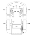
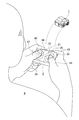
- the electric automobile toy 1 has a small plastic vehicle body having a total length of about several tens of millimeters, and an electric part built in the vehicle body is provided at the bottom thereof.
- a power receiving end receptacle 117 (see reference numerals 117a and 117b in FIG. 4) is provided at both ends of the double layer capacitor.
- the power receiving end receptacle 117 (see reference numerals 117a and 117b in FIG. 4) is coupled to the power supply end plug 203 (203a, 203b) or 215 (215a, 215b) of the charger 2A or 2B when charging. Is done.
- the left front wheel 101 is rotatably supported by a support member 105 that rotates about a shaft 108 via an axle.
- the right front wheel 102 is rotatably supported by a support member 106 that rotates about a shaft 109 via an axle.
- the left and right support members 105 and 106 are connected via a link rod 107.
- a steering magnet 110 which is a permanent magnet, is fixed to the left support member 105, and a steering coil (excitation coil) 112 constituting an electromagnet is disposed at a position opposite to the steering magnet 110.
- the right support A steering magnet 111 which is a permanent magnet, is fixed to the member 106, and a steering coil (excitation coil) 113 that constitutes an electromagnet is disposed at a position facing the member. Therefore, by energizing the left steering coil 112, the steering magnet 110 can be attracted and the left steering operation can be performed. Conversely, by energizing the right steering coil 113, the steering magnet 111 can be energized. Can be steered to the right. Therefore, the left and right support members 105 and 106, the left and right steering magnets 110 and 111, and the link rod 107 constitute a steering mechanism, and the left and right steering coils 112 and 113 constitute a steering drive source. When no steering coil is energized, the steering mechanism is returned to the left and right neutral positions by a biasing member (not shown) such as a spring.
- a biasing member not shown
- the left and right rear wheels 103 and 104 are supported integrally and rotatably via a rear wheel axle 114.
- the rotational power obtained from the rotary motor 115 includes a small-diameter gear fixed to the output shaft of the rotary motor, a medium-diameter gear that rotates integrally with the intermediate shaft, and a small-diameter gear that rotates integrally with the intermediate shaft. Then, it is transmitted to the right rear wheel via a gear train 116 in which large-diameter gears fixed to the rear wheel axle are sequentially meshed. Therefore, the gear train 116 composed of four gears constitutes a rear wheel rotation mechanism, and the rotary motor 115 constitutes a rear wheel motor.
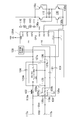
- an electric double layer capacitor 118 which is a main part of the present invention is provided at the first stage of the circuit constituting the electric automobile toy 1.
- the illustrated electric double layer capacitor 118 is constituted by a single capacitor element having a relatively small capacity (for example, about 1 to 5 F).
- the positive side terminal (+) of the electric double layer capacitor 118 is connected to a positive side line conducting to one of the pair of receiving end receptacles 117a, and the negative side terminal ( ⁇ ) is connected to the other of the pair of receiving end receptacles. It is connected to the negative line conducting to 117b. Therefore, the electric double layer capacitor 118 can be charged by connecting the power supply end plugs (203a, 203b or 215a, 215b) of the charger described above to the power receiving end receptacles 117a, 117b.
- the positive terminal (+) of the electric double layer capacitor 118 is also connected to one of the pair of input terminals 119a of the step-up DC / DC converter 20 of the chopper type, and the negative terminal ( ⁇ ) is also It is connected to the other 119b of the pair of input terminals of the chopper type boosting DC / DC converter 20.
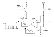
- the step-up DC / DC converter 20 includes a series coil 122 that is a cored coil, a DC / DC converter IC 123, a Schottky diode 124, an input-side parallel capacitor 125 that is an electrolytic capacitor, and an electrolytic capacitor. And the output side parallel capacitor 126.
- the DC / DC converter IC 123 has a deviation between the output voltage of the converter 20 detected via the two voltage dividing resistors 123b and 123c and the reference voltage 123d corresponding to the target output voltage.
- a transistor chopper 123a a transistor chopper 123a.
- the transistor chopper 123 a is switched at high speed in synchronization with the pulse train obtained from the PWM circuit 123, whereby the input voltage (charge of the electric double layer capacitor 118 is obtained) at the input terminals 119 a and 119 b. Voltage) is appropriately boosted and constant by the action of the series coil 122, the input-side parallel capacitor 125, the output-side parallel capacitor 126, and the Schottky diode 124, and this is then output from the output terminals 127a and 127b to the control circuit.
- a transistor bridge circuit (four transistors 130a, 130b, 130c) having an action of switching the direction of the voltage applied to the rear wheel motor 115 in addition to being supplied to the constituent infrared receiving IC 128 and CPU (configured by a microprocessor) 129 , 13 Composed d) supply to 130.
- the chopper type step-up DC / DC converter 20 uses the ON / OFF operation of the transistor chopper 123a and the inductive action of the coil 122 to absorb the electric charge from the electric double layer capacitor 118 constituting the power supply. Therefore, the use efficiency of the power source is high, and therefore, the electric charge stored in the electric double layer capacitor 118 can be used without leaving.
- a power supply switch for turning on / off the power supply to those load circuits 120 is provided.
- the illustrated power supply switch 120 includes a so-called unipolar overturn (SPDT) type contact capable of selectively connecting a movable piece 120d conducting to a common terminal 120c to a first terminal 120a and a second terminal 120b.
- SPDT unipolar overturn
- the on / off operation can be performed via an operation element 120e formed of an appropriate movable mechanism.
- the state where the movable piece 120d is connected to the second terminal 120b corresponds to the on state of the power supply switch 120.
- the load circuit (including the rotary motor 115, the CPU 129, and the infrared receiving IC 128) is connected in series, and power is supplied from the DC / DC converter 20 to the load circuit.
- the state where the movable piece 120d is connected to the first terminal 120a corresponds to the OFF state of the power supply switch 120. In this OFF state, when the movable piece 120d is connected to the first terminal 120a, the positive side line and the negative side line on the output side of the DC / DC converter 20 are short-circuited via the short-circuit line 121.
- the power supply voltage applied to the CPU 129 can be instantaneously reset to zero. Therefore, when the power supply switch 120 is switched from the OFF state to the ON state after that, the power supply voltage applied to the CPU 129 surely rises from zero volts instantaneously, and the power-on reset function incorporated in the CPU 129 is normal. It is possible to start up an arbitrary program with certainty by operating it.
- a photodiode 128a for receiving a modulated infrared (command) signal and converting it into an electric signal, and an electric signal obtained from the photodiode 128a at an appropriate level Amplifying the input unit 128b, the electric signal obtained from the input unit 128b to a certain level, a variable gain amplifying unit and a filtering unit 128c for extracting a signal having a target frequency from the input unit 128b, and generating a reference clock signal
- the oscillating unit 128e and a control unit 128f that controls the operation of the variable gain amplifying unit, the filtering unit 128e, and the demodulating unit 128d in synchronization with the clock signal obtained from the oscillating unit 128e are configured.
- the demodulated electrical (command) signal obtained from the demodulator 128 is supplied to a CPU 129 described later.
- the modulated infrared (command) signal received by the infrared receiver IC is transmitted from an infrared remote controller (hereinafter referred to as an infrared remote controller) 3 as shown in FIG. is there.
- an infrared remote controller hereinafter referred to as an infrared remote controller 3 as shown in FIG. is there.
- the infrared remote controller 3 is provided with a turbo button 35 and an energy saving button 36.
- the player 4 selectively operates the left turn button 31 and the right turn button 32 with the thumb 44 of the right hand, and selectively operates the forward button 33 and the reverse button 34 with the left thumb 42.
- the turbo button 35 is operated with the right index finger 43
- the energy saving button is operated with the left index finger 41.
- buttons 31 to 36 When any of these buttons 31 to 36 is operated, a control command corresponding to the operated button is generated and transmitted to the electric toy car 1 as a corresponding modulated infrared (command) signal.
- the CPU 129 functioning as a central processing unit is constituted by a microprocessor.
- the CPU 129 has one input port IN and five output ports OUT0 to OUT4. .
- the input port IN is for taking in a demodulated electrical (command) signal output from the infrared receiving IC 128.
- the output ports OUT0 to OUT2 are for selectively driving the left and right steering coils 112 and 113.
- OUT3 and OUT4 are for switching the direction of current flowing through the rear wheel motor 115 by appropriately turning on and off the four transistors 130a to 130d constituting the transistor bridge circuit 130.
- the microprocessor functioning as the CPU 129 further incorporates a so-called power-on reset function that normally starts the program based on the fact that the power supply voltage detected via the power supply terminal VDD rises from zero. .
- the voltage of the power supply line immediately before the rise of the power supply voltage must be close to zero volts. As described above, this is a short-circuit line in the off state of the power supply switch 120.
- the power supply line in the control circuit is short-circuited through 121, and the charge stored in the capacitive component is guaranteed by being completely discharged.
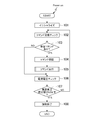
- step 101 the initialization process
- step 101 the command reception check process
- step 102 the command reception check process
- step 105 the command execution process
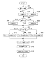
- step 201 when the process is started, it is determined whether the command is a forward command or a reverse command (step 201). If the command is a forward command (step 201 forward), the process of storing the forward setting (step 202) is performed in reverse. In the case of a command (reverse step 201), a process (step 203) for storing the reverse setting is executed.
- step 204 it is determined whether the content of the steering direction command is a right turn, a straight drive, or a left turn (step 204), and in the case of a left turn, a process of storing a left turn setting (step 205) according to each determination result.
- a process for storing the right turn setting (step 206) is performed.
- straight traveling in particular, it is possible to perform a straight traveling operation by the action of the return spring of the steering mechanism without performing anything.
- step 207 the mode is the normal mode, the turbo mode, or the energy saving mode.
- the duty ratio setting (medium) is stored (step 208).
- a process for storing the ratio setting (large) (step 209) and a process for storing the duty ratio setting (small) (step 210) are executed in the case of the energy saving mode.
- the corresponding bridge switching signal is output from the output port OUT3 or OUT4 depending on whether the forward setting or the backward setting is stored, and the four transistors 130a to 130d constituting the transistor bridge circuit 130 are output.
- the rear wheel motor 115 is energized in a direction corresponding to either forward or reverse.
- a PWM pulse train having an appropriate duty ratio is generated depending on whether the duty ratio setting is large, medium, or small, and a pair of transistors (130a and 130d constituting the transistor bridge circuit 130 are generated. Or 130c and 130b) and one base (130d or 130b).
- the car toy 1 will travel with the contents instructed from the infrared remote controller 3.
- the automobile toy 1 can be run at a low speed, thereby avoiding the consumption of the electric double layer capacitor, thereby realizing a longer run. .
- the present invention by providing the step-up DC / DC converter 20 on the output side of the electric double layer capacitor 118, the holding time of the power supply voltage supplied to the load circuit has been extended. Nevertheless, it is recognized that the power supply voltage obtained in this way rapidly decreases when the charging voltage of the electric double layer capacitor 118 falls below the minimum operating voltage (Vth0) of the DC / DC converter 20 (see FIGS. 16 and 17). . Therefore, in this example, as shown in FIG. 11, the power supply voltage is constantly monitored (step 106), and becomes a power supply voltage specified value (Vth 2) or less that is assumed that a sudden voltage drop will occur soon (after ⁇ t).
- step 107 If so (step 107 YES), it is decided to prevent the microprocessor from entering an unstable state by forcibly terminating the program being executed (step 108).
- VDD power supply voltage
- the step-up DC / DC converter 20 is interposed on the output side of the electric double layer capacitor 118 to boost and stabilize the output voltage of the electric double layer capacitor 118. It seems that the value of the stabilization voltage applied to the control circuit is not necessarily a constant value during operation. Then, if the value of this stabilization voltage can be changed at any time by the user side, it should be possible to construct a more convenient power supply circuit, and by using this, an electric double layer capacitor can be formed. The charge of 118 can be made longer lasting. Therefore, in this example, the output voltage of the DC / DC converter 20 can be changed at an arbitrary time by performing an energy saving mode setting operation from the infrared remote controller.
- control for selecting one of two types of resistors 123 b and 123 b ′ having different values from the outside as a voltage dividing resistor for output voltage detection is used.
- a DC / DC converter IC 123A having a terminal CNT is used.
- FIG. 10 by designating the logical value of the control terminal CNT, one of the two analog switches 123g and 123h is turned on, and either the resistor 123b or the resistor 123b ′ can be selected.
- the output voltage target value can be set to either VH or VL.
- the charging voltage of the electric double layer capacitor 118 is detected from the input port IN2 via the detection line 131, and the DC / DC converter IC 123A is controlled from the output port OUT5.
- the terminal CNT can be operated.
- the energy saving mode flag is set. F is set (step 302), and when the energy saving mode cancel command is decoded (step 303 YES), a process for resetting the energy saving mode flag F (step 304) is incorporated.
- step 109 YES when the energy saving mode flag F is in the set state (step 109 YES), the input voltage of the DC / DC converter 20 is checked, and the value is set to a specific voltage (Vth3) set in advance.
- Vth3 a specific voltage set in advance.
- a program that reduces the value of the set output voltage of the DC / DC converter 20 from VH to VL is incorporated (see FIG. 17).
- the value of the target holding voltage of the DC / DC converter is changed (for example, VH To VL), the running duration can be extended.
- this target holding voltage changing operation can be used in various other ways.
- the initial target holding voltage is set to a low value, but after a certain period of time has elapsed, the DC / DC converter output voltage is reduced to near the end of the capacitor discharge by setting it higher. By compensating for the tendency, the DC / DC converter output can be made uniform over the entire discharge period.
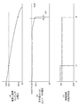
- the step-up DC / DC converter 20 includes a power supply voltage (operation guarantee voltage) necessary for the operation of the control circuit (for example, the infrared reception IC 128 or the CPU 129, 129A). ) From the lowest operable voltage (operation guarantee voltage) Vth0 (about 0.7V) lower than Vth1 (for example, about 2.5V) and the power supply voltage Vth1 (for example, 2.5V) necessary for the operation of the control circuit Has a high constant output voltage (output holding voltage) Vth4 (for example, 3.3 V).
- the value of the output voltage of the DC / DC converter 20 can be substantially maintained at a constant output voltage higher than the power supply voltage Vth1 necessary for the operation of the control circuit. Even if the main power source is used, it is possible to secure an operation duration t2 per charge that is long enough to satisfy users such as infants and lower-grade children. If there is no DC / DC converter, it goes without saying that the operation duration is significantly reduced to t1.
- a 50 mA load circuit (assumed on the output side of a DC / DC converter (synchronous step-up DC / DC converter IC (PFM control) manufactured by Silicon Power Electronics, model number SP9262)) is assumed.
- a load circuit when 4 types of electric double layer capacitors (1.0 F, 1.5 F, 2.0 F, 3.3 F) having different electrostatic capacities are charged to 3 V with a considerably large load circuit connected.
- the operation duration (t1, t2) was roughly as follows. Capacitance t1 t2 1.0 F 3 seconds 24 seconds 1.5 F 4 seconds 31 seconds 2.0 F 8 seconds 46 seconds 3.3 F 12 seconds 62 seconds
- the output voltage of the DC / DC converter drops to the preset voltage Vth3.
- the value of the target output voltage of the DC / DC converter can be automatically changed from VH to VL, and the power supply voltage maintaining time can be extended from time t2 to time t2 ′.
- the battery charger 2A has a horizontally long rectangular parallelepiped casing 201 having a relatively small thickness.
- the casing 201 accommodates a circuit board on which two AA alkaline batteries constituting a charging power source and a charging circuit (see FIG. 4) are mounted.
- a support base 202 for placing the car toy 1 and a power receiving end receptacle 117 (reference numerals 117a, 117 in FIG. 4) at the bottom of the car toy 1 placed on the support base 202.
- An LED display lamp 207 for displaying that the battery is currently being charged is provided on the side surface of the housing 201.
- the power receiving end recess pull 117 (shown in FIG. 4) provided on the bottom surface of the vehicle toy 1 is provided.
- 117a and 117b) and the power supply end plug 203 (see reference numerals 203a and 203b in FIG. 4) provided on the upper surface of the battery charger 2A are coupled to each other, and the toy car 1 is firmly fixed on the housing 201.
- a charging path is formed from the charging power source built in the battery charger 2A to the electric double layer capacitor 118 built in the car toy 1.
- the hand-powered generator-type charger 2B has a somewhat vertically long casing 212 that can be gripped with the left hand.
- a right hand operation handle 213 for operating an AC generator 216 (see FIG. 5) housed in the housing 212 is provided on the right side surface of the housing 212.
- a support base 214 for placing the car toy 1 and a power receiving end receptacle 117 at the bottom of the car toy 1 placed on the support base 214 (reference numeral in FIG. 4).
- 117a and 117b) and a power supply end plug 215 see reference numerals 215a and 215b in FIG. 5).
- FIG. 2 (b) when the automobile toy 1 is placed on the support base 214 of the hand-powered generator-type charger 2B, the power receiving end recess pull 117 (FIG. 4) provided on the bottom surface of the automobile toy 1 is shown.
- the power toy plug 215 (refer to reference numerals 215a and 215b in FIG. 5) provided on the upper surface of the hand-powered charger 2B is coupled, and the toy car 1 is securely mounted on the housing 212.
- a charging path is formed from the charging power source built in the hand-powered generator charger 2B to the electric double layer capacitor 118 built in the toy car 1.
- the electric double layer capacitor 118 built in the toy car is charged in combination with the action of the constant voltage circuit described later. It can be performed.
- FIG. 2B in the state where the automobile toy 1 is placed on the support base 214 of the hand-powered generator-type charger 2B, the front wheels 101 and 102 and the rear wheels 103 and 104 of the automobile toy Since a gap ⁇ L is formed between the upper surface of the battery-type charger 2A, the steering motion of the front wheels 101 and 102 and the rotational motion of the rear wheels 103 and 104 are allowed even during charging. Even if charging is started while the power supply switch 120 (see FIG. 6) is turned on by mistake, there is no possibility that the toy car 1 is detached from the battery charger 2A and dropped.
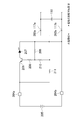
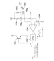
- the circuit of the battery-type charger has a 3V DC power source 205 formed by connecting two AA alkaline batteries in series.
- the power supply end plugs 203a and 203b are connected to the power receiving end recess pulls 117a and 117b, charging of the electric double layer capacitor 118 is started via the resistor (1 ⁇ ) 211.
- the resistor (1 ⁇ ) 211.
- the electric double layer capacitor 118 is empty, the voltage between the terminals is almost zero, so that the base current is supplied to the transistor (type 2SA950) 206 via the resistor (200 ⁇ ) 210 and the resistor (200 ⁇ ) 208.
- the voltage between the terminals of the capacitor 118 rises to near 3.0 V, and when the base-emitter voltage of the transistor 206 falls below the PN junction forward voltage, the transistor 206 is turned off and the LED lamp 207 is turned off. To do.
- the LED display lamp 207 is not lit by the action of the resistance (1.2 k ⁇ ) 209. Therefore, the user can easily know whether or not the charging is completed simply by observing the lighting state of the LED lamp 207.
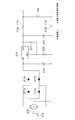
- the circuit of the hand-powered generator charger includes an AC generator 216 that generates power by rotating the handwheel 213, and a diode bridge type all-rectifier that rectifies the output AC voltage of the AC generator 216.
- Wave rectifier circuits 217a to 217d an electrolytic capacitor 218 that smoothes the output voltage of the full wave rectifier circuit, and a stabilization circuit that stabilizes the DC voltage smoothed by this electrolytic capacitor 218 (voltage stabilizing IC 219 and output)
- the voltage dividing resistors 220 and 221 for voltage detection are provided, and after the power supply end plugs 215a and 215b are connected to the power receiving end recess pulls 117a and 117b, the handwheel 213 is rotated to operate the voltage stabilizing circuit. Due to the action, 3V appears almost stably in the power supply plugs 215a and 215b regardless of the generated voltage. , Without causing overcharging, it is possible to perform appropriate charging of the electric double layer capacitor 118.
- the LED display lamp 207 waits until the LED display lamp 207 is turned on to turn off, and after the toy 1 is removed from the charger 2A, the battery is fully charged to about 3V. Toy 1 can be obtained. Since the battery with a built-in charger is approximately 3 V, there is no risk of overcharging, and if there is a poor contact between the plug and the receptacle, the LED display lamp 207 will not light up, so there is no misunderstanding that charging is complete. Although the charging station time varies depending on the capacitance of the capacitor 118, for example, in the case of the capacitor 118 of about 1 to 3F, charging is completed within about 10 seconds.
- the housing 212 is grasped with the left hand and the handle 213 is rotated with the right hand. Then, power is generated with a voltage of 3 V or more by the action of the built-in generator 216, but the voltage stabilization IC 219 constituting the voltage stabilization circuit causes almost 3 V between the power supply plugs 215a and 215b. Therefore, the electric double layer capacitor 118 is charged to about 3V without causing overcharge.
- the electric car toy system comprising the hand-powered charger 2B and the car toy 1 with an electric double layer capacitor built-in, a small and lightweight electric car toy system can be realized without using any battery. .
- the charging station time varies depending on the capacitance of the capacitor 118, for example, in the case of the capacitor 118 of about 1 to 3F, charging is completed within about 15 seconds.
- the toy 1 in the state where the toy 1 is fixed to the charger 2A or 2B, the front wheel and the rear wheel of the toy 1 are in a free state, so that the power switch is inadvertently turned on. Even if charging is started, the toy 1 is not detached from the charger 2A or 2B due to an unexpected movement of the toy 1 by remote control operation. Moreover, since the toy 1 is directly fixed to the charger 2A or 2B, there is an advantage that it is easy to handle and can be stored compactly without drawing an electric cord for charging.
- the power switch 120 Before driving the electric toy car 1, first, the power switch 120 is switched from the off state to the on state by operating the operation element 120 e, and the output voltage of the DC / DC converter is changed to the power source. Power is supplied to the transistor bridge circuit 130 of the wheel rotation motor 115, the CPU 129 that is a control circuit, and the infrared receiving IC 128.
- a modulated infrared signal including a control command corresponding to the operation content is emitted from the infrared remote controller 3, and this is an infrared receiving IC 128 on the car toy 1 side.
- the control command received and demodulated by the CPU 129 is further decoded and executed by the microprocessor constituting the CPU 129.
- the car toy 1 is driven in the running mode (front / rear, left / right). Usually, it will run by turbo, energy saving).
- the charging voltage of the electric double layer capacitor 118 gradually decreases linearly from the initial voltage (about 3V) as shown in FIG.
- the power supply voltage Vth1 for example, about 2.5V
- the output voltage of the DC / DC converter 20 is substantially maintained at the set holding voltage Vth4 (for example, 3.3 V). It will not interfere with the operation of the circuit.
- the output voltage of the DC / DC converter 20 is decreased slightly as shown in FIG. 16B, the output voltage of the electric double layer capacitor 118 applied to the input side is
- the power supply voltage Vth1 required for the operation of the control circuit is maintained to be equal to or higher than time t2 until the minimum required voltage Vth0 (for example, about 0.7V determined by the input threshold value of the element) is reached (FIG. 16 ( a)).
- the control circuit operates normally until time t2, and the traveling duration of the electric automobile toy 1 is extended from time t1 to time t2 due to the presence of the DC / DC converter 20. Become.
- the running duration of the toy car is about 4 to 8 seconds (DC / DC It was extended from a state where no converter was present) to about several tens of seconds (a state where a DC / DC converter was present). From this, according to the present invention, it can be manufactured in a small size, light weight and at a low cost, and a sufficient running duration per charge can be guaranteed, and in addition, repeated charging can cause deterioration of the charging element. Therefore, it was confirmed that a long-life electric car toy can be provided.
- the energy saving mode flag F is set on the side of the car toy 1 as shown in the flowchart of FIG. Then, as shown in the flowchart of FIG. 14, the value of the output holding voltage of the DC / DC converter 20 is VH after waiting for the input voltage of the DC / DC converter 20 to fall below a predetermined voltage Vth3. To VL. Then, as shown in the graph of FIG. 17, the value of the output voltage of the DC / DC converter 20 is changed from VH (about 3.3 V), which is the initial output holding voltage, to a predetermined output holding voltage VL lower than that. As a result, the power consumption of the load is reduced due to a decrease in the power supply voltage to the load, and the voltage of the capacitor 118 is prolonged, so that the running duration is extended from time t2 to time t2 ′.
- the operation duration time of the electric toy can be extended by maintaining the power supply voltage supplied to the load circuit for a long time. It was found that the supplied power supply voltage rapidly decreases immediately before the electric charge of the electric double layer capacitor 118 disappears. This is because, in a microprocessor that is executing an arbitrary program, if the power supply voltage is suddenly reduced, the operation becomes unstable, causing an unexpected malfunction. Therefore, in the present embodiment, as shown in the flowchart of FIG. 11, when the power supply voltage reaches the voltage Vth2 (refer to the graph of FIG. 16) that is just before the voltage suddenly decreases (before ⁇ t) (see the graph of FIG. 16). The program being executed is forcibly terminated forcibly so as to prevent an unexpected malfunction of the microprocessor due to a sudden decrease in power supply voltage thereafter.
- the operation duration time of the electric toy 1 can be extended by maintaining the power supply voltage fed to the load circuit for a long time. It has been found that this type of chopper boost DC / DC converter 20 has a high capacitance component on the output side due to the influence of a built-in capacitor. Therefore, there is a possibility that the charging voltage remains on the output side power supply line of the DC / DC converter 20 even after the power supply switch 120 is turned off. This is a serious problem when a microprocessor is included in the control circuit constituting the load circuit.
- the power-on reset function also referred to as power-on clear processing
- the planned program can be started normally. If the power supply line voltage does not rise from zero volts when the power is turned on, the power-on reset function may not work well. Therefore, in the present embodiment, as shown in FIG. 6, when the power supply switch 120 is turned off, the positive and negative power supply lines are short-circuited on the output side of the DC / DC converter 20 via the short-circuit line 121. Thus, the charged charge is discharged, and the zero reset of the power supply line can be surely performed.
- the present invention is applied to a load circuit having a control circuit.
- a power source and a drive source are simply connected via a switch, such as a train toy continuously running on a circular rail.
- the present invention can also be applied to an electric mobile toy that does not substantially have a control circuit.
- the present invention is not limited to a vehicle toy having a control circuit, but is also applied to a self-propelled vehicle toy that is said to travel while discovering an obstacle by itself and avoiding it. Can do.
- the present invention is widely applicable not only to mobile toys such as automobiles, trains, and airplanes, but also to electric toys that are non-moving bodies such as fixed swing doll toys.
- the electric toy of the present invention in addition to being able to be manufactured in a small size and light weight, it is possible to sufficiently satisfy a user such as an infant or a lower grade child while using an electric double layer capacitor as a main power source. Therefore, it is possible to secure an operation duration per charge.
- SYMBOLS 1 Electric vehicle toy 2A Battery type charger 2B Manual power generation type charger 3 Infrared remote control 4 Player 20 Boost type DC / DC converter 101 Left front wheel 102 Right front wheel 103 Left rear wheel 104 Right rear wheel 105 Left front wheel support member 106 Supporting member for right front wheel 107 Left and right connecting rod 108 Turning shaft for left front wheel 109 Turning shaft for right front wheel 110 Steering magnet for left turn 111 Steering magnet for right turn 112 Steering coil for left turn 113 Steering coil for right turn 114 Rear axle DESCRIPTION OF SYMBOLS 115 Electric motor for driving
Abstract
Description
-充電に必要な機構-
図1(a)に示されるように、電動式自動車玩具1は、この例にあっては、全長数10mm程度の小型のプラスチック製車体を有し、その底部には、車体に内蔵される電気二重層キャパシタの両端に導通する受電端レセプタクル117(図4の符号117a,117b参照)が設けられている。この受電端レセプタクル117(図4の符号117a,117b参照)は、後述するように、充電に際しては、充電器2A又は2Bの給電端プラグ203(203a,203b)又は215(215a,215b)と結合される。 <Mechanical structure of electric car toy>
-Mechanisms required for charging-
As shown in FIG. 1 (a), in this example, the
図3に示されるように、左右の前輪101,102のうち、左の前輪101は、軸108を中心に回動する支持部材105に車軸を介して回転自在に支持されており、同様に、右の前輪102は、軸109を中心として回動する支持部材106に車軸を介して回転自在に支持されている。左右の支持部材105と106は、リンクロッド107を介して連結されている。さらに、左の支持部材105には永久磁石である操舵磁石110が固定され、これと対向する位置には電磁石を構成する操舵コイル(励磁コイル)112が配置されており、同様に、右の支持部材106には永久磁石である操舵磁石111が固定され、これと対向する位置には電磁石を構成する操舵コイル(励磁コイル)113が配置されている。そのため、左側の操舵コイル112へ通電を行うことで、操舵磁石110を吸引して左側への操舵操作を行うことができ、逆に、右側の操舵コイル113へ通電を行うことで、操舵磁石111を吸引して右側への操舵操作を行うことができる。したがって、左右の支持部材105、106と左右の操舵磁石110、111とリンクロッド107とが操舵機構を構成し、左右の操舵コイル112,113が操舵駆動源を構成する。なお、いずれの操舵コイルにも通電されていないとき、この操舵機構はスプリング等の図示しない付勢部材により左右の中立位置に復帰されている。 -Front wheel steering mechanism and steering drive source-
As shown in FIG. 3, of the left and right
図3に示されるように、左右の後輪103,104は、後輪車軸114を介して一体的に回転自在に支持されている。そして、回転電動機115から得られる回転動力は、当該回転電動機の出力軸に固定された小径歯車と、中間軸と一体に回転する中径歯車と、当該中間軸と一体的に回転する小径歯車と、後輪車軸に固定された大径歯車とを順次に噛合させてなる歯車列116を介して、右後輪に伝達される。そのため、4個の歯車からなる歯車列116が後輪回転機構を構成し、回転電動機115が後輪電動機を構成する。 -Rear wheel rotation mechanism and rear wheel motor-
As shown in FIG. 3, the left and right
-電気二重層キャパシタ-
図6に示されるように、電気式自動車玩具1を構成する回路の初段には、本発明の要部であるところの電気二重層キャパシタ118が設けられている。図示の電気二重層キャパシタ118は、比較的に小容量(例えば、1乃至5F程度)を有する単一のキャパシタ素子にて構成されている。この電気二重層キャパシタ118の正側端子(+)は、一対の受電端レセプタクルの一方117aに導通する正側ラインに接続されるとともに、負側端子(-)は、一対の受電端レセプタクルの他方117bに導通する負側ラインに接続されている。したがって、前述した充電器の給電端プラグ(203a,203b又は215a,215b)を受電端レセプタクル117a,117bに挿抜結合することにより、電気二重層キャパシタ118への充電が可能とされている。 <Circuit configuration of electric car toy>
-Electric double layer capacitor-
As shown in FIG. 6, an electric
この例では、昇圧型DC/DCコンバータ20は、コア入りコイルである直列コイル122と、DC/DCコンバータIC123と、ショットキーダイオード124と、電解キャパシタである入力側の並列キャパシタ125と、電解キャパシタである出力側の並列キャパシタ126とを含んで構成されている。 -Step-up DC / DC converter using chopper method (Part 1)-
In this example, the step-up DC / DC converter 20 includes a
図6に示されるように、電気二重層キャパシタ118から負荷回路(赤外線受信IC128,CPU129,トランジスタブリッジ回路130等々)に至る給電路には、それらの負荷回路への給電をオンオフするための給電スイッチ120が設けられている。図示の給電スイッチ120は、共通端子120cに導通する可動片120dを、第1の端子120aと第2の端子120bとに択一的に接続可能な所謂単極双倒(SPDT)型接点を備え、適宜な可動機構からなる操作子120eを介してオンオフ操作可能とされている。そして、可動片120dが第2の端子120bと接続している状態が、この給電スイッチ120のオン状態に相当し、この状態では、電源となる電気二重層キャパシタ118と、DC/DCコンバータ20と、負荷回路(回転電動機115、CPU129、赤外線受信IC128を含む)が一連に接続されて、DC/DCコンバータ20から負荷回路へと給電が行われる。逆に、可動片120dが第1の端子120aと接続している状態が、この給電スイッチ120のオフ状態に相当する。このオフ状態にあっては、可動片120dが第1の端子120aと接続することにより、短絡線121を介して、DC/DCコンバータ20の出力側の正側ラインと負側ラインとは短絡される。その結果、給電スイッチ120がオフされた時点で、出力側の並列キャパシタ126等の容量成分に電荷が残存していたとしても、それらの容量成分に残存する電荷は、短絡線121を介して瞬時に放電されるため、CPU129に印加される電源電圧を瞬時にゼロリセットすることができる。そのため、その後、給電スイッチ120をオフ状態からオン状態に切り換えた場合には、CPU129へ印加される電源電圧は、確実にゼロボルトから瞬時に立ち上がることとなり、CPU129に組み込まれたパワーオンリセット機能を正常に作動させることにより、任意のプログラムを確実に起動させることができる。 -Power switch-
As shown in FIG. 6, in a power supply path from the electric
図8に示されるように、赤外線受信IC128の内部には、変調赤外線(コマンド)信号を受信して電気信号に変換するためのフォトダイオード128aと、フォトダイオード128aから得られる電気信号を適宜のレベルに増幅する入力部128bと、入力部128bから得られる電気信号を一定レベルに増幅するとともに、これから目的とする周波数の信号を抽出する可変利得増幅部及び濾波部128cと、基準クロック信号を生成する発振部128eと、発振部128eから得られるクロック信号に同期して、前記可変利得増幅部及び濾波部128eや復調部128dの動作を制御する制御部128fとを含んで構成されている。そして、復調部128から得られる復調電気(コマンド)信号は、後述するCPU129へと供給される。 -Infrared receiver IC-
As shown in FIG. 8, inside the
中央処理ユニットとして機能するCPU129はマイクロプロセッサで構成されたものであり、図6に示される例にあっては、1個の入力ポートINと、5個の出力ポートOUT0~OUT4を有している。入力ポートINは、赤外線受信IC128から出力される復調電気(コマンド)信号を取り込むためのものである。出力ポートOUT0~OUT2は、左右の操舵コイル112,113を選択的に駆動するためのものである。OUT3とOUT4は、トランジスタブリッジ回路130を構成する4個のトランジスタ130a~130dを適宜にオンオフ設定することにより、後輪電動機115に流れる電流の方向を切り換えるためのものである。 -CPU configured with a microprocessor-
The
-電動自動車玩具の操縦関係プログラム-
図11に示されるように、電源投入(Power on)によりパワーオンリセット機能が働いて、プログラムの実行が開始されると、まず、イニシャライズ処理(ステップ101)を実行して、演算に必要な各種のフラグやレジスタのリセットをしたのち、続いて、コマンド受信チェック処理(ステップ102)を実行することにより、入力ポートIN(図6参照)を介して取り込んだ変調電気(コマンド)信号に基づいて、なんらかのコマンドを受信したか否かをチェックする。ここで、受信コマンドありと判定されたときには(ステップ103YES)、当該コマンドを解読したのち(ステップ104)、その解読結果に応じたコマンド実行処理(ステップ105)を実行する。 <Program to be executed by the microprocessor constituting the CPU>
-Steering program for electric car toys-
As shown in FIG. 11, when the power-on reset function is activated by turning on the power (Power on) and the execution of the program is started, first, the initialization process (step 101) is executed to perform various operations required for the calculation. After resetting the flags and registers, the command reception check process (step 102) is executed, and based on the modulated electrical (command) signal taken in via the input port IN (see FIG. 6), Check if any command is received. If it is determined that there is a received command (YES in step 103), the command is decoded (step 104), and then a command execution process (step 105) corresponding to the decoded result is executed.
本発明によれば、電気二重層キャパシタ118の出力側に、昇圧型のDC/DCコンバータ20を設けたことにより、負荷回路へ給電される電源電圧の保持時間の長期化を成し遂げはしたが、それでも、こうして得られた電源電圧は、電気二重層キャパシタ118の充電電圧がDC/DCコンバータ20の最低作動電圧(Vth0)を下回ると、急激に低下することが認められる(図16,17参照)。そのため、この例では、図11に示されるように、電源電圧を常時に監視して(ステップ106)、電圧急減がまもなく(Δt後に)起こると想定される電源電圧規定値(Vth2)以下となったならば(ステップ107YES)、実行中のプロクラムを強制終了することにより、マイクロプロセッサが不安定な状態に陥ることを未然に回避することとした(ステップ108)。このような構成を採用したことにより、突然に、電源電圧(VDD)が急減して、マイクロプロセッサ129の動作が不安定になることに起因する誤動作を未然に回避することができる。 -Program for countermeasures against sudden decrease in DC / DC converter output
According to the present invention, by providing the step-up DC / DC converter 20 on the output side of the electric
本発明にあっては、電気二重層キャパシタ118の出力側に昇圧型のDC/DCコンバータ20を介在させることにより、電気二重層キャパシタ118の出力電圧を昇圧かつ安定化するものであるが、負荷となる制御回路に与える安定化電圧の値は、必ずしも、運転中に常に一定値である必要はないものと思われる。それならば、この安定化電圧の値をユーザの側でいつでも変更できるものとすれば、より使い勝手のよい電源回路を構成することができるはずであり、またこれを利用することで、電気二重層キャパシタ118の充電電荷をより長持ちさせることもできる筈である。そのため、この例にあっては、任意の時点で赤外線リモコンから省エネモード設定操作を行うことにより、その時点で、DC/DCコンバータ20の出力電圧を変更可能とした。 -Energy-saving measures program by changing the setting value of DC / DC converter-
In the present invention, the step-up DC / DC converter 20 is interposed on the output side of the electric
本実施形態においては、図16のグラフに示されるように、昇圧型のDC/DCコンバータ20は、制御回路(例えば、赤外線受信IC128やCPU129,129A)の作動に必要な電源電圧(動作保証電圧)Vth1(例えば、2.5V程度)よりも低い動作可能な最低電圧(動作保証電圧)Vth0(約0.7V)と、制御回路の作動に必要な電源電圧Vth1(例えば、2.5V)よりも高い一定の出力電圧(出力保持電圧)Vth4(例えば、3.3V)を有する。 -Power supply voltage maintaining action of this embodiment-
In the present embodiment, as shown in the graph of FIG. 16, the step-up DC / DC converter 20 includes a power supply voltage (operation guarantee voltage) necessary for the operation of the control circuit (for example, the
静電容量 t1 t2
1.0 F 3秒 24秒
1.5 F 4秒 31秒
2.0 F 8秒 46秒
3.3 F 12秒 62秒 Therefore, according to the present embodiment, even if the charging voltage of the electric
Capacitance t1 t2
1.0
-電池式充電器-
図1(a)に示されるように、電池式充電器2Aは、厚さの比較的に薄い横長直方体状の筐体201を有する。この筐体201には、充電用電源を構成する2本の単三アルカリ電池と充電回路(図4参照)を搭載する回路基板が収容される。筐体201の上面には、自動車玩具1を載置するための支持台部202と、支持台部202に載置された自動車玩具1の底部にある受電端レセプタクル117(図4の符号117a,117b参照)に結合されるべき給電端プラグ203(図4の符号203a,203b参照)とを有する。筐体201の側面には、現在充電中であることを表示するためのLED表示ランプ207が設けられている。 <Mechanical structure of charger>
-Battery charger-
As shown in FIG. 1A, the
図2(a)に示されるように、手回し発電式充電器2Bは、左手で把持可能な幾分縦長の筐体212を有する。この筐体212の右側面には、筐体212の内部に収容された交流発電機216(図5参照)を動作させるための右手操作用の手回しハンドル213が設けられている。一方、筐体212の上面には、自動車玩具1を載置するための支持台部214と、支持台部214に載置された自動車玩具1の底部にある受電端レセプタクル117(図4の符号117a,117b参照)に結合されるべき給電端プラグ215(図5の符号215a,215b参照)とを有する。 -Hand-powered charger-
As shown in FIG. 2A, the hand-powered generator-
-電池式充電器-
図4に示されるように、電池式充電器の回路は、2個の単三アルカリ乾電池を直列接続してなる3V直流電源205を有する。給電端プラグ203a,203bと受電端レセクタプル117a,117bとを結合すると、抵抗(1Ω)211を介して、電気二重層キャパシタ118に対する充電が開始される。当初、電気二重層キャパシタ118が空の状態であれば、端子間電圧はほぼゼロとなることから、抵抗(200Ω)210及び抵抗(200Ω)208を介して、トランジスタ(型式2SA950)206にベース電流が流れ、トランジスタ206がオンして、充電状態にあることを表示するためのLED表示ランプ(vf=1.9V)207が点灯する。充電が進んで、キャパシタ118の端子間電圧が3.0V近くまで上昇し、トランジスタ206のベース・エミッタ間電圧がPN接合順方向電圧を下回ると、トランジスタ206がオフして、LEDランプ207は消灯する。プラグ203a,203bとレセプタクル117a,117bとの接触不良があるときには、抵抗(1.2kΩ)209の作用でLED表示ランプ207は点灯しない。したがって、ユーザはLEDランプ207の点灯状態を観察するだけで、充電完了有無を容易に知ることができる。 <Circuit configuration of charger>
-Battery charger-
As shown in FIG. 4, the circuit of the battery-type charger has a 3V
図5に示されるように、手回し発電式充電器の回路は、手回しハンドル213の回転で発電作用を行う交流発電機216と、この交流発電機216の出力交流電圧を整流するダイオードブリッジ式の全波整流回路217a~217dと、その全波整流回路の出力電圧を平滑化する電解キャパシタ218と、この電解キャパシタ218で平滑化された直流電圧を安定化する安定化回路(電圧安定化IC219と出力電圧検出用の分圧抵抗220,221等を備えている。そして、給電端プラグ215a,215bと受電端レセクタプル117a,117bとを結合したのち、手回しハンドル213を回転操作すると、電圧安定化回路の作用により、発電電圧の如何に拘わらず、給電端プラグ215a,215bにはほぼ安定的に3Vが現れるから、過充電を生ずることなく、電気二重層キャパシタ118に対する適切な充電を行うことができる。 -Hand-powered charger-
As shown in FIG. 5, the circuit of the hand-powered generator charger includes an
-自動車玩具の充電-
自動車玩具1に内蔵された電気二重層キャパシタ118を充電するには、先ず、操作子120eを適宜に操作して、給電スイッチ(図6参照)120をオフしたのち、充電器側のプラグと玩具側のレセプタクル117a,117bとの結合を介して、充電器(電池式充電器2A又は手回し発電式充電器2B)に玩具1をしっかりと固定させる。 <Operation of Electric Car Toy According to Embodiment>
-Charging car toys-
In order to charge the electric
電動式自動車玩具1を運転するに際しては、まず、それに先立ち、操作子120eの操作により、給電スイッチ120をオフ状態からオン状態に切り替えて、DC/DCコンバータの出力電圧を、動力源である後輪回転モータ115のトランジスタブリッジ回路130、制御回路であるCPU129、及び赤外線受信IC128へと給電する。 -Driving electric car toys-
Before driving the
赤外線リモコン3において省エネモードボタン36(図15参照)が操作されると(図15参照)、自動車玩具1の側では、図13のフローチャートに示されるように、省エネモードフラグFがセットされる。すると、図14のフローチャートに示されるように、DC/DCコンバータ20の入力電圧が、予め規定された電圧Vth3以下に低下するのを待って、DC/DCコンバータ20の出力保持電圧の値はVHからVLへと切り替えられる。すると、図17のグラフに示されるように、DC/DCコンバータ20の出力電圧の値は、当初の出力保持電圧であるVH(約3.3V)からそれよりも低い所定の出力保持電圧VLへと切り替わり、これにより負荷に対する給電電圧の低下により、負荷の消費電力が低減されて、キャパシタ118の電圧が長持ちすることにより、走行継続時間は時刻t2から時刻t2'へと延長される。 -More special measures to extend travel duration-
When the energy saving mode button 36 (see FIG. 15) is operated on the infrared remote controller 3 (see FIG. 15), the energy saving mode flag F is set on the side of the
本発明によれば、DC/DCコンバータ20を設けたことにより、負荷回路に給電される電源電圧を長期に保持させることで、電動玩具の動作継続時間を延長できたが、その反面、こうして延長された電源電圧は、電気二重層キャパシタ118の電荷が消滅する直前に急減することが判明した。これは、すなわち、任意のプログラムの実行中のマイクロプロセッサにおいて、その電源電圧が急減すると、動作が不安定となり、予期せぬ誤動作の原因となるからである。そこで、本実施形態では、図11のフローチャートに示されるように、電源電圧がそのように急減する寸前(Δt前)の電圧である電圧Vth2(図16のグラフ参照)になったならば、直ちに、実行中のプログラムを安全に強制終了することにより、その後の電源電圧急減によるマイクロプロセッサの予期せぬ誤動作を未然に回避するように仕組まれている。 -Measures for sudden reduction of power supply voltage-
According to the present invention, since the DC / DC converter 20 is provided, the operation duration time of the electric toy can be extended by maintaining the power supply voltage supplied to the load circuit for a long time. It was found that the supplied power supply voltage rapidly decreases immediately before the electric charge of the electric
本発明によれば、DC/DCコンバータ20を設けたことにより、負荷回路に給電される電源電圧を長期に保持させることで、電動式玩具1の動作継続時間を延長できたが、その反面、この種のチョッパ方式の昇圧型DC/DCコンバータ20には内蔵キャパシタの影響などで、出力側の容量成分が高いことが判明した。そのため、DC/DCコンバータ20の出力側電源ラインは、給電スイッチ120がオフされたのちにあっても、充電電圧が残留するおそれがある。これは、負荷回路を構成する制御回路にマイクロプロセッサが含まれている場合に、大きな問題となる。すなわち、マイクロプロセッサにあっては、電源投入と共に、内蔵するパワーオンリセット機能(パワーオンクリア処理とも言う)を作動させることにより、予定されているプログラムを正常に起動させることができるのであるが、電源投入時に電源ラインの電圧がゼロボルトから立ち上がらないと、パワーオンリセット機能がうまく作動しないことがあるのである。そこで、本実施形態では、図6に示されるように、給電スイッチ120がオフされるときには、短絡線121を介して、DC/DCコンバータ20の出力側において、正負の電源ラインが短絡されるようにして、充電電荷を放電して、確実な電源ラインのゼロリセットを可能としたものである。 -Countermeasures for DC / DC converter output side capacitance component-
According to the present invention, by providing the DC / DC converter 20, the operation duration time of the
以上の説明では、本発明を制御回路を有する負荷回路に適用したが、例えば、円形レール上を継続的に走行する電車玩具等のように、単に電源と駆動源とをスイッチを介して接続したに過ぎない、実質的に制御回路を有しない電動式移動体玩具にも本発明は適用できることは勿論である。また、制御回路を有する自動車玩具についても、遠隔操作されるものに限らず、自ら障害物を発見してこれを回避しつつ走行すると言った自走式の自動車玩具にも本発明は適用することができる。さらに、本発明は、自動車、電車、航空機と言った移動体玩具のみならず、固定式の揺動人形玩具等のように、非移動体である電動式玩具にも広く適用可能である。 <Others>
In the above description, the present invention is applied to a load circuit having a control circuit. For example, a power source and a drive source are simply connected via a switch, such as a train toy continuously running on a circular rail. Of course, the present invention can also be applied to an electric mobile toy that does not substantially have a control circuit. In addition, the present invention is not limited to a vehicle toy having a control circuit, but is also applied to a self-propelled vehicle toy that is said to travel while discovering an obstacle by itself and avoiding it. Can do. Furthermore, the present invention is widely applicable not only to mobile toys such as automobiles, trains, and airplanes, but also to electric toys that are non-moving bodies such as fixed swing doll toys.
2A 電池式充電器
2B 手回し発電式充電器
3 赤外線リモコン
4 遊技者
20 昇圧型のDC/DCコンバータ
101 左前輪
102 右前輪
103 左後輪
104 右後輪
105 左前輪の支持部材
106 右前輪の支持部材
107 左右連結ロッド
108 左前輪の旋回軸
109 右前輪の旋回軸
110 左折用の操舵磁石
111 右折用の操舵磁石
112 左折用の操舵コイル
113 右折用の操舵コイル
114 後輪車軸
115 走行用の電動機
116 ギア列
117,117a,117b 受電端レセクタプル
118 電気二重層キャパシタ
119a,119b 電気二重層キャパシタの充電電圧端子
120 電源スイッチ
120a,120b,120c 電源スイッチの端子
120d 電源スイッチの可動片
120e 電源スイッチの操作子
121 短絡線
122 鉄心入りコイル
123 昇圧型DC/DCコンバータIC
123A 昇圧型DC/DCコンバータIC
123a トランジスタチョッパ
123b,123c,123b' 抵抗
123d 基準電圧
123e 偏差増幅器
123f PWM回路
123g,123g' アナログスイッチ(AS)
123h インバータ
124 ショットキーダイオード
125 電解キャパシタ
126 キャパシタ
127 電解キャパシタ
128 赤外線受信IC
128a 赤外線受光ダイオード
128b 入力部
128c 可変利得増幅部及び濾波部
128d 復調部
128e 発振部
128f 制御部
129 制御用のCPU
130 トランジスタブリッジ回路
130a,130b,130c,130d ブリッジ回路を構成するトランジスタ
131 電圧検出線
201 筐体
202 支持台部
203,203a,203b 給電端プラグ
204a,204b 電源電圧端子
205 直流電源(電池)
206 トランジスタ
207 LED表示ランプ
208~211 抵抗
212 筐体
213 手回しハンドル
214 支持台部
215a,215b 給電端プラグ
216 交流発電機
217a,217b,217c,217d 全波整流回路を構成するダイオード
218 電解キャパシタ
219 電圧安定化IC
220,221 抵抗
222 キャパシタ
ΔL 隙間
Vth0 DC/DCコンバータの作動限界入力電圧(動作保証電圧)
Vth1 負荷となる制御回路の作動限界電圧(動作保証電圧)
Vth2 DC/DCコンバータの出力電圧が急降下する寸前電圧
Vth3 電気二重層キャパシタの充電電圧が低下したことを判定するための閾値電圧 DESCRIPTION OF
123A Boost DC / DC Converter IC
128a Infrared
DESCRIPTION OF
206
220, 221
Vth1 Operation limit voltage of the control circuit that becomes the load (operation guarantee voltage)
Vth2 Voltage just before the output voltage of the DC / DC converter suddenly drops Vth3 Threshold voltage for determining that the charging voltage of the electric double layer capacitor has dropped
Claims (18)
- 主電源となる電気二重層キャパシタと、
玩具としての機能を実現するための可動機構と、
前記可動機構を動作させるための電気式動力源と、
前記電気二重層キャパシタから受け取った電圧を昇圧して、少なくとも、前記電気式動力源の電源として給電するためのチョッパ方式による昇圧型のDC/DCコンバータとを包含する、電動式玩具。 An electric double layer capacitor as a main power source;
A movable mechanism for realizing the function as a toy;
An electric power source for operating the movable mechanism;
An electric toy including a step-up DC / DC converter of a chopper type for boosting a voltage received from the electric double layer capacitor and supplying power as a power source of the electric power source. - 前記電気式動力源の動作を制御するための制御回路をさらに有し、
前記チョッパ方式による昇圧型のDC/DCコンバータは、前記電気二重層キャパシタから受け取った電圧を昇圧して、前記制御回路の電源としても給電するものであり、
前記昇圧型のDC/DCコンバータは、さらに
定電圧出力機能を有し、かつ
前記制御回路の作動に必要な電源電圧よりも低い動作可能な最低入力電圧と、
前記制御回路の作動に必要な電源電圧よりも高い一定出力電圧と、を有する、請求項1に記載の電動式玩具。 A control circuit for controlling the operation of the electric power source;
The step-up DC / DC converter using the chopper method boosts the voltage received from the electric double layer capacitor and supplies power as a power source for the control circuit,
The step-up DC / DC converter further has a constant voltage output function, and can operate at a lower input voltage lower than a power supply voltage necessary for the operation of the control circuit.
The electric toy according to claim 1, having a constant output voltage higher than a power supply voltage required for operation of the control circuit. - 前記制御回路への給電をオンオフするための電源スイッチと、
前記電源スイッチがオフのとき、前記DC/DCコンバータの出力側において電源ライン間を短絡させて、前記制御回路への印加電圧をゼロリセットするための短絡線とをさらに有する、請求項2に記載の電動式玩具。 A power switch for turning on and off the power supply to the control circuit;
The short circuit line for short-circuiting between power lines on the output side of the DC / DC converter and resetting the voltage applied to the control circuit to zero when the power switch is off. Electric toy. - 前記制御回路は、CPUとして機能するマイクロプロセッサを含み、かつ
前記マイクロプロセッサには、前記DC/DCコンバータの出力電圧が、ゼロボルトへ向けて急降下する直前の値として予め設定された所定電圧にまで降下したことを検出して、プログラムの実行を強制的に終了させる機能が組み込まれている、請求項2又は3に記載の電動式玩具。 The control circuit includes a microprocessor functioning as a CPU, and the microprocessor drops the output voltage of the DC / DC converter to a predetermined voltage set in advance as a value immediately before suddenly dropping toward zero volts. The electric toy according to claim 2 or 3, wherein a function for detecting that the program has been executed and forcibly terminating the execution of the program is incorporated. - 前記制御回路は、CPUとして機能するマイクロプロセッサを含み、かつ
前記マイクロプロセッサには、前記電気二重層キャパシタの充電電圧を検出し、その検出値に応じて、前記DC/DCコンバータの出力電圧設定値を変更する機能が組み込まれている、請求項2又は3に記載の電動式玩具。 The control circuit includes a microprocessor functioning as a CPU, and the microprocessor detects a charging voltage of the electric double layer capacitor, and an output voltage setting value of the DC / DC converter according to the detected value The electric toy according to claim 2 or 3, wherein a function for changing the function is incorporated. - 前記可動機構が、
自動車玩具としての機能を実現するための前輪操舵機構及び後輪回転機構であり、
前記電気式動力源が、
前記前輪操舵機構を動作させるための操舵駆動源および前記後輪回転機構を動作させるための後輪電動機であり、
前記制御回路が、
与えられた制御コマンドに応じて、前記操舵駆動源及び前記後輪電動機を制御する機能を有するものである、請求項2に記載の電動式玩具。 The movable mechanism is
A front wheel steering mechanism and a rear wheel rotation mechanism for realizing a function as an automobile toy,
The electric power source is
A steering drive source for operating the front wheel steering mechanism and a rear wheel motor for operating the rear wheel rotation mechanism;
The control circuit comprises:
The electric toy according to claim 2, having a function of controlling the steering drive source and the rear wheel electric motor in accordance with a given control command. - 前記制御回路が、
CPUとして機能するマイクロプロセッサを含み、かつ
前記マイクロプロセッサには、
与えられた制御コマンドを解読及び実行することにより、少なくとも、前記操舵駆動源及び前記後輪電動機を制御する機能と、
パワーオンリセット機能とが、少なくとも、組み込まれており、さらに
前記制御回路への給電をオンオフするための電源スイッチと、
前記電源スイッチがオフのとき、前記DC/DCコンバータの二次側の電源ライン間を短絡させて、前記制御回路への印加電圧をゼロリセットするための短絡線とをさらに有する、請求項6に記載の電動式玩具。 The control circuit comprises:
Including a microprocessor functioning as a CPU, and the microprocessor includes:
A function of controlling at least the steering drive source and the rear wheel motor by decoding and executing a given control command;
A power-on reset function is incorporated at least, and a power switch for turning on and off the power supply to the control circuit;
The power supply switch further includes a short-circuit line for short-circuiting between power supply lines on the secondary side of the DC / DC converter and resetting an applied voltage to the control circuit to zero when the power switch is off. The electric toy described. - 前記マイクロプロセッサには、
前記DC/DCコンバータの出力電圧が、ゼロボルトへと急降下する直前の値として予め設定された所定電圧にまで降下したことを検出して、プログラムの実行を強制的に終了させる機能が、さらに、組み込まれている、請求項7に記載の電動式玩具。 The microprocessor includes
A function for detecting that the output voltage of the DC / DC converter has dropped to a predetermined voltage set in advance as a value immediately before suddenly dropping to zero volts and forcibly terminating the execution of the program is further incorporated. The electric toy according to claim 7, wherein - 前記マイクロプロセッサには、
前記電気二重層キャパシタの充電電圧を検出し、その検出値に応じて、前記DC/DCコンバータの出力電圧設定値を変更する機能が、さらに、組み込まれている、請求項7に記載の電動式玩具。 The microprocessor includes
The electric type according to claim 7, further comprising a function of detecting a charging voltage of the electric double layer capacitor and changing an output voltage setting value of the DC / DC converter according to the detected value. toy. - 前記マイクロプロセッサには、
前記後輪電動機に対して電圧パルス列を印加することにより、前記後輪電動機に流れる電流を設定する機能と、
前記与えられた制御コマンドが省エネコマンドのとき、前記パルス列のパルス幅、パルス周波数、および/または、デューティ比を変更することにより、前記前記後輪電動機に流れる電流を減少させる機能とが、さらに、組み込まれている、請求項7に記載の電動式玩具。 The microprocessor includes
A function of setting a current flowing through the rear wheel motor by applying a voltage pulse train to the rear wheel motor;
When the given control command is an energy saving command, the function of reducing the current flowing through the rear wheel motor by changing the pulse width, pulse frequency, and / or duty ratio of the pulse train, The electric toy according to claim 7, which is incorporated. - 前記制御回路には、所定の変調方式により無線送信された制御コマンドを受信復調して前記マイクロプロセッサに与える受信復調ICを、さらに、含み、
前記マイクロプロセッサは、所定のリモートコントローラから無線送信された制御コマンドを前記受信復調ICを介して受け取って解読及び実行する、請求項6~10のいずれか1つに記載の電動式玩具。 The control circuit further includes a reception demodulation IC that receives and demodulates a control command wirelessly transmitted by a predetermined modulation method and gives the control command to the microprocessor,
The electric toy according to any one of claims 6 to 10, wherein the microprocessor receives a control command wirelessly transmitted from a predetermined remote controller via the reception demodulation IC and decodes and executes the control command. - 前記電動式玩具に対して着脱が可能であって、前記電動式玩具に内蔵された前記電気二重層キャパシタに対して充電が可能な充電器を有する、請求項1~5のいずれか1つに記載の電動式玩具。 The charger according to any one of claims 1 to 5, further comprising a charger that can be attached to and detached from the electric toy and that can charge the electric double layer capacitor built in the electric toy. The electric toy described.
- 前記充電器は、
前記電動式玩具側の一対の受電端と接続されるべき一対の給電端と、
1又は2以上の電池で構成され、充電目標電圧とほぼ等しく設定された出力電圧を有する充電用電源部と、
前記充電用電源部から前記給電端へ至る経路に介在され、前記電気二重層キャパシタへ流れ込む充電電流を制限するための抵抗と、
前記一対の給電端子と前記一対の受電端子とが電気的に導通し、かつ前記一対の給電端子間の電圧が前記充電目標電圧にまで上昇する期間に限り点灯する表示ランプとを有する、請求項12に記載の電動式玩具。 The charger is
A pair of power feeding ends to be connected to the pair of power receiving ends on the electric toy side;
A power supply unit for charging, which is composed of one or two or more batteries and has an output voltage set substantially equal to a target charging voltage;
A resistor for limiting a charging current flowing into the electric double layer capacitor, interposed in a path from the charging power supply unit to the power supply end;
The pair of power feeding terminals and the pair of power receiving terminals are electrically connected to each other, and have a display lamp that is lit only during a period when the voltage between the pair of power feeding terminals rises to the charging target voltage. 12. The electric toy according to 12. - 前記充電器は、
前記電動式玩具側の一対の受電端と接続されるべき一対の給電端と、
手動発電機から構成され、かつ直流電圧を出力する充電用電源部と、
前記充電用電源部から得られる電圧を平滑及び充電目標電圧に安定化する平滑安定化回路とを有する、請求項12に記載の電動式玩具。 The charger is
A pair of power feeding ends to be connected to the pair of power receiving ends on the electric toy side;
A power supply unit for charging, which is composed of a manual generator and outputs a DC voltage;
The electric toy according to claim 12, further comprising a smoothing and stabilizing circuit that stabilizes a voltage obtained from the charging power supply unit to a smoothing and charging target voltage. - 前記電動式玩具に対して着脱が可能であって、前記電動式玩具に内蔵された前記電気二重層キャパシタに対して充電が可能な充電器を有する、請求項6~11のいずれか1つに記載の電動式玩具。 The charger according to any one of claims 6 to 11, further comprising a charger that can be attached to and detached from the electric toy and that can charge the electric double layer capacitor built in the electric toy. The electric toy described.
- 前記充電器は、
前記電動式玩具を構成する自動車玩具側の一対の受電端と接続されるべき一対の給電端と、
1又は2以上の電池で構成され、充電目標電圧とほぼ等しく設定された出力電圧を有する充電用電源部と、
前記充電用電源部から給電端へ至る経路に介在され、前記電気二重層キャパシタへ流れ込む充電電流を制限するための抵抗と、
前記一対の給電端子と前記一対の受電端子とが導通し、かつ前記一対の給電端子間の電圧が前記充電目標電圧まで上昇する期間に限り点灯する表示ランプとを有し、かつ
前記一対の給電端は、
手持ち型の充電器筐体の外表面に設けられ、かつ前記自動車玩具の車体底部に設けられた一対の受電端プラグ又は受電端レセクタプルと、前記自動車玩具の後輪を浮かせた状態で、挿抜結合されるべき給電端レセクタプル又は給電端プラグとして構成されている、請求項15に記載の電動式玩具。 The charger is
A pair of power receiving ends to be connected to a pair of power receiving ends on the car toy side constituting the electric toy;
A power supply unit for charging, which is composed of one or two or more batteries and has an output voltage set substantially equal to a target charging voltage;
A resistor for limiting a charging current flowing into the electric double layer capacitor, which is interposed in a path from the charging power supply unit to the power feeding end;
The pair of power supply terminals and the pair of power reception terminals are electrically connected and have a display lamp that is lit only during a period when the voltage between the pair of power supply terminals rises to the charge target voltage; The end is
A pair of power receiving end plugs or power receiving end recess pulls provided on the outer surface of the handheld charger housing and provided on the bottom of the car toy, and the rear wheel of the car toy are inserted and removed. The electric toy according to claim 15, which is configured as a power supply endless pull or power supply end plug to be performed. - 前記充電器は、
前記電動式玩具側の一対の受電端と接続されるべき一対の給電端と、
手動発電機から構成され、かつ直流電圧を出力する充電用電源部と、
前記充電用電源部から得られる電圧を平滑及び充電目標電圧に安定化する平滑安定化回路とを有し、かつ
前記一対の給電端は、
手持ち型の充電器筐体の外表面に設けられ、かつ前記自動車玩具の車体底部に設けられた一対の受電端プラグ又は受電端レセクタプルと、前記自動車玩具の後輪を浮かせた状態で、挿抜結合されるべき給電端レセクタプル又は給電端プラグとして構成されている、請求項16に記載の電動式玩具。 The charger is
A pair of power feeding ends to be connected to the pair of power receiving ends on the electric toy side;
A power supply unit for charging, which is composed of a manual generator and outputs a DC voltage;
A smoothing and stabilizing circuit that stabilizes the voltage obtained from the power supply unit for charging to a smoothing and charging target voltage, and the pair of power supply ends includes:
A pair of power receiving end plugs or power receiving end recess pulls provided on the outer surface of the handheld charger housing and provided on the bottom of the car toy, and the rear wheel of the car toy are inserted and removed. The electric toy according to claim 16, wherein the electric toy is configured as a feed end recess pull or a feed end plug to be performed. - 主電源となる電気二重層キャパシタと、
玩具としての機能を実現するための可動機構と、
前記可動機構を動作させるための電気式動力源と、
前記電気式動力源の動作を制御するための制御回路と、
前記電気二重層キャパシタから受け取った電圧を昇圧して、少なくとも、前記制御回路の電源として給電するための昇圧型のDC/DCコンバータとを包含する電動式玩具において、
前記制御回路に含まれるマイクロプロセッサを、前記DC/DCコンバータの出力電圧が、ゼロボルトへと急降下する直前の値として予め設定された所定電圧にまで降下したことを検出して、プログラムの実行を強制的に終了させるように機能させるためのコンピュータプログラム。 An electric double layer capacitor as a main power source;
A movable mechanism for realizing the function as a toy;
An electric power source for operating the movable mechanism;
A control circuit for controlling the operation of the electric power source;
In the electric toy that boosts the voltage received from the electric double layer capacitor and includes at least a step-up DC / DC converter for supplying power as the power source of the control circuit,
The microprocessor included in the control circuit is forced to execute the program by detecting that the output voltage of the DC / DC converter has dropped to a predetermined voltage set in advance as a value immediately before suddenly dropping to zero volts. A computer program that functions to end automatically.
Priority Applications (5)
| Application Number | Priority Date | Filing Date | Title |
|---|---|---|---|
| CN201490001509.1U CN206777865U (en) | 2014-07-08 | 2014-07-08 | Battery-operated toy |
| JP2014553376A JP5717267B1 (en) | 2014-07-08 | 2014-07-08 | Electric toy |
| EP14896992.6A EP3147008B1 (en) | 2014-07-08 | 2014-07-08 | Electrically powered toy |
| US14/407,287 US9950269B2 (en) | 2014-07-08 | 2014-07-08 | Electrically-operated toy |
| PCT/JP2014/068224 WO2016006044A1 (en) | 2014-07-08 | 2014-07-08 | Electrically powered toy |
Applications Claiming Priority (1)
| Application Number | Priority Date | Filing Date | Title |
|---|---|---|---|
| PCT/JP2014/068224 WO2016006044A1 (en) | 2014-07-08 | 2014-07-08 | Electrically powered toy |
Publications (1)
| Publication Number | Publication Date |
|---|---|
| WO2016006044A1 true WO2016006044A1 (en) | 2016-01-14 |
Family
ID=53277398
Family Applications (1)
| Application Number | Title | Priority Date | Filing Date |
|---|---|---|---|
| PCT/JP2014/068224 WO2016006044A1 (en) | 2014-07-08 | 2014-07-08 | Electrically powered toy |
Country Status (5)
| Country | Link |
|---|---|
| US (1) | US9950269B2 (en) |
| EP (1) | EP3147008B1 (en) |
| JP (1) | JP5717267B1 (en) |
| CN (1) | CN206777865U (en) |
| WO (1) | WO2016006044A1 (en) |
Families Citing this family (5)
| Publication number | Priority date | Publication date | Assignee | Title |
|---|---|---|---|---|
| EP3147008B1 (en) | 2014-07-08 | 2018-07-04 | Tomy Company, Ltd. | Electrically powered toy |
| US20170117730A1 (en) * | 2015-06-26 | 2017-04-27 | The Regents Of The University Of California | Efficient supercapacitor charging technique by a hysteretic charging scheme |
| CN106390468A (en) * | 2016-07-11 | 2017-02-15 | 苏州南江乐博机器人有限公司 | Ball hitting control device and ball hitting control method |
| WO2022239384A1 (en) * | 2021-05-10 | 2022-11-17 | 日本たばこ産業株式会社 | Power supply unit for aerosol generation device |
| WO2022239383A1 (en) * | 2021-05-10 | 2022-11-17 | 日本たばこ産業株式会社 | Power supply unit for aerosol generation device |
Citations (6)
| Publication number | Priority date | Publication date | Assignee | Title |
|---|---|---|---|---|
| JPH0241982Y2 (en) * | 1982-08-04 | 1990-11-08 | ||
| JPH0639148A (en) * | 1992-07-21 | 1994-02-15 | Tomy Ltd | Operation controlling device |
| JPH0631796U (en) * | 1992-09-30 | 1994-04-26 | 株式会社タカラ | Car toy |
| JP2004109138A (en) * | 2003-09-29 | 2004-04-08 | Seiko Epson Corp | Electronic apparatus |
| JP2010093888A (en) * | 2008-10-06 | 2010-04-22 | Nippon Reliance Kk | Power supply apparatus |
| JP3173871U (en) * | 2011-12-13 | 2012-02-23 | 株式会社セプト・ワン | Kokeshi with LED built-in |
Family Cites Families (12)
| Publication number | Priority date | Publication date | Assignee | Title |
|---|---|---|---|---|
| JPH0649466B2 (en) | 1988-08-03 | 1994-06-29 | 日産車体株式会社 | Pillar structure of vehicle body |
| JPH0418594A (en) | 1990-05-12 | 1992-01-22 | Mitsubishi Electric Corp | Plasma display device |
| JPH0418594U (en) * | 1990-06-05 | 1992-02-17 | ||
| JPH0631796A (en) | 1992-07-14 | 1994-02-08 | Chisso Corp | Polyolefin resin-made hollow container |
| US20060258261A1 (en) * | 2005-05-10 | 2006-11-16 | Tse Celement C S | Two-phase stepper motor driven toys |
| WO2006125019A2 (en) * | 2005-05-16 | 2006-11-23 | Maxwell Technologies, Inc. | Low voltage electrical vehicle propulsion system using double layer capacitors |
| JP2009153357A (en) * | 2007-12-19 | 2009-07-09 | Akimasa Shinoyama | Boosting circuit for solar motor |
| TWI566814B (en) * | 2008-11-21 | 2017-01-21 | 通路實業集團國際公司 | Inductive toy vehicle |
| US8860359B2 (en) * | 2009-10-09 | 2014-10-14 | Illinois Institute Of Technology | Hybrid energy storage system |
| US8337274B1 (en) * | 2011-10-31 | 2012-12-25 | Silverlit Limited | Motor booster for toy vehicle |
| KR101370688B1 (en) | 2012-04-25 | 2014-03-06 | 문성원 | The radio van plaything keep easy charge means |
| EP3147008B1 (en) | 2014-07-08 | 2018-07-04 | Tomy Company, Ltd. | Electrically powered toy |
-
2014
- 2014-07-08 EP EP14896992.6A patent/EP3147008B1/en active Active
- 2014-07-08 US US14/407,287 patent/US9950269B2/en active Active
- 2014-07-08 CN CN201490001509.1U patent/CN206777865U/en active Active
- 2014-07-08 WO PCT/JP2014/068224 patent/WO2016006044A1/en active Application Filing
- 2014-07-08 JP JP2014553376A patent/JP5717267B1/en active Active
Patent Citations (6)
| Publication number | Priority date | Publication date | Assignee | Title |
|---|---|---|---|---|
| JPH0241982Y2 (en) * | 1982-08-04 | 1990-11-08 | ||
| JPH0639148A (en) * | 1992-07-21 | 1994-02-15 | Tomy Ltd | Operation controlling device |
| JPH0631796U (en) * | 1992-09-30 | 1994-04-26 | 株式会社タカラ | Car toy |
| JP2004109138A (en) * | 2003-09-29 | 2004-04-08 | Seiko Epson Corp | Electronic apparatus |
| JP2010093888A (en) * | 2008-10-06 | 2010-04-22 | Nippon Reliance Kk | Power supply apparatus |
| JP3173871U (en) * | 2011-12-13 | 2012-02-23 | 株式会社セプト・ワン | Kokeshi with LED built-in |
Non-Patent Citations (1)
| Title |
|---|
| See also references of EP3147008A4 * |
Also Published As
| Publication number | Publication date |
|---|---|
| JP5717267B1 (en) | 2015-05-13 |
| CN206777865U (en) | 2017-12-22 |
| EP3147008A4 (en) | 2017-05-17 |
| EP3147008B1 (en) | 2018-07-04 |
| JPWO2016006044A1 (en) | 2017-04-27 |
| US20160271507A1 (en) | 2016-09-22 |
| US9950269B2 (en) | 2018-04-24 |
| EP3147008A1 (en) | 2017-03-29 |
Similar Documents
| Publication | Publication Date | Title |
|---|---|---|
| JP5717267B1 (en) | Electric toy | |
| TW201214919A (en) | Hybrid battery module and battery management method | |
| WO2012017833A1 (en) | Electric tool adaptor and electric tool system using same | |
| CN111051192B (en) | Wireless actuating system for bicycle transmission | |
| WO2012072024A1 (en) | Automatic walking device, charging station, docking system and docking method | |
| WO2017122450A1 (en) | Battery-shaped power supply device equipped with wireless communication function | |
| JP4933298B2 (en) | Communication system, battery pack, and battery pack connection device | |
| JP5964303B2 (en) | Battery pack and battery pack charging method | |
| JP2014200118A (en) | Battery-driven apparatus and battery pack | |
| JP2014144699A (en) | Electric bicycle and charger, circuit | |
| JP2013070535A (en) | Wireless power supply adaptable electric power supply apparatus, electric power tool, charger, and electrical machine | |
| JP2006006640A (en) | Power supply unit for battery type toy | |
| CN111656862B (en) | Portable induction heater | |
| JP2009239989A (en) | Charger | |
| WO2013024090A3 (en) | Operation of an illuminant at an autonomous energy store | |
| US20080258676A1 (en) | Toy vehicle capable of collecting solar power | |
| JP2007203101A (en) | Vacuum cleaner | |
| CN211930507U (en) | Frequency converter with fault detection circuit | |
| JP2004283476A (en) | Manual power generation toy | |
| WO2012073194A1 (en) | Battery chargers | |
| JP6089211B2 (en) | Rechargeable vacuum cleaner | |
| CN209821641U (en) | Multi-boot selection module for scooter controller for children | |
| JP2007203100A (en) | Vacuum cleaner | |
| CN109952689B (en) | Battery-type power supply device and battery-driven load device | |
| JP5818964B2 (en) | Wireless control toy |
Legal Events
| Date | Code | Title | Description |
|---|---|---|---|
| ENP | Entry into the national phase |
Ref document number: 2014553376 Country of ref document: JP Kind code of ref document: A |
|
| WWE | Wipo information: entry into national phase |
Ref document number: 14407287 Country of ref document: US |
|
| 121 | Ep: the epo has been informed by wipo that ep was designated in this application |
Ref document number: 14896992 Country of ref document: EP Kind code of ref document: A1 |
|
| REEP | Request for entry into the european phase |
Ref document number: 2014896992 Country of ref document: EP |
|
| WWE | Wipo information: entry into national phase |
Ref document number: 2014896992 Country of ref document: EP |
|
| NENP | Non-entry into the national phase |
Ref country code: DE |