WO2016003222A1 - 무선 통신 시스템에서 단말의 동작 방법 및 이를 이용하는 단말 - Google Patents
무선 통신 시스템에서 단말의 동작 방법 및 이를 이용하는 단말 Download PDFInfo
- Publication number
- WO2016003222A1 WO2016003222A1 PCT/KR2015/006837 KR2015006837W WO2016003222A1 WO 2016003222 A1 WO2016003222 A1 WO 2016003222A1 KR 2015006837 W KR2015006837 W KR 2015006837W WO 2016003222 A1 WO2016003222 A1 WO 2016003222A1
- Authority
- WO
- WIPO (PCT)
- Prior art keywords
- terminal
- network
- cell
- interworking
- procedure
- Prior art date
Links
Images


Classifications
-
- H—ELECTRICITY
- H04—ELECTRIC COMMUNICATION TECHNIQUE
- H04W—WIRELESS COMMUNICATION NETWORKS
- H04W76/00—Connection management
- H04W76/10—Connection setup
- H04W76/15—Setup of multiple wireless link connections
- H04W76/16—Involving different core network technologies, e.g. a packet-switched [PS] bearer in combination with a circuit-switched [CS] bearer
-
- H—ELECTRICITY
- H04—ELECTRIC COMMUNICATION TECHNIQUE
- H04W—WIRELESS COMMUNICATION NETWORKS
- H04W24/00—Supervisory, monitoring or testing arrangements
- H04W24/10—Scheduling measurement reports ; Arrangements for measurement reports
-
- H—ELECTRICITY
- H04—ELECTRIC COMMUNICATION TECHNIQUE
- H04W—WIRELESS COMMUNICATION NETWORKS
- H04W76/00—Connection management
- H04W76/10—Connection setup
-
- H—ELECTRICITY
- H04—ELECTRIC COMMUNICATION TECHNIQUE
- H04W—WIRELESS COMMUNICATION NETWORKS
- H04W12/00—Security arrangements; Authentication; Protecting privacy or anonymity
- H04W12/08—Access security
-
- H—ELECTRICITY
- H04—ELECTRIC COMMUNICATION TECHNIQUE
- H04W—WIRELESS COMMUNICATION NETWORKS
- H04W12/00—Security arrangements; Authentication; Protecting privacy or anonymity
- H04W12/10—Integrity
-
- H—ELECTRICITY
- H04—ELECTRIC COMMUNICATION TECHNIQUE
- H04W—WIRELESS COMMUNICATION NETWORKS
- H04W48/00—Access restriction; Network selection; Access point selection
- H04W48/20—Selecting an access point
-
- H—ELECTRICITY
- H04—ELECTRIC COMMUNICATION TECHNIQUE
- H04W—WIRELESS COMMUNICATION NETWORKS
- H04W88/00—Devices specially adapted for wireless communication networks, e.g. terminals, base stations or access point devices
- H04W88/02—Terminal devices
- H04W88/06—Terminal devices adapted for operation in multiple networks or having at least two operational modes, e.g. multi-mode terminals
-
- H—ELECTRICITY
- H04—ELECTRIC COMMUNICATION TECHNIQUE
- H04W—WIRELESS COMMUNICATION NETWORKS
- H04W92/00—Interfaces specially adapted for wireless communication networks
- H04W92/02—Inter-networking arrangements
-
- H—ELECTRICITY
- H04—ELECTRIC COMMUNICATION TECHNIQUE
- H04W—WIRELESS COMMUNICATION NETWORKS
- H04W12/00—Security arrangements; Authentication; Protecting privacy or anonymity
- H04W12/60—Context-dependent security
- H04W12/69—Identity-dependent
- H04W12/73—Access point logical identity
Definitions
- the present invention relates to wireless communication, and more particularly, to a method of operating a terminal for interworking between heterogeneous networks in a wireless communication system and a terminal using the same.
- 3GPP LTE long term evolution
- UMTS Universal Mobile Telecommunications System
- 3GPP LTE uses orthogonal frequency division multiple access (OFDMA) in downlink and single carrier-frequency division multiple access (SC-FDMA) in uplink.
- OFDMA orthogonal frequency division multiple access
- SC-FDMA single carrier-frequency division multiple access
- LTE-A 3GPP LTE-Advanced
- the wireless communication system can support providing a terminal with a service through a plurality of access networks.
- a terminal may be provided with a service from a 3GPP access network, which is a mobile wireless communication system, and may also be provided from a non-3GPP access network such as a worldwide interoperability for microwave access (WiMAX) or a wireless local area network (WLAN). You can get services.
- a 3GPP access network which is a mobile wireless communication system
- a non-3GPP access network such as a worldwide interoperability for microwave access (WiMAX) or a wireless local area network (WLAN). You can get services.
- WiMAX worldwide interoperability for microwave access
- WLAN wireless local area network
- a UE When a UE establishes a connection with a 3GPP access network and receives a service, and a traffic overload occurs in the 3GPP access network, it is recommended that the terminal handle the traffic to be processed through another access network, that is, a non-3GPP access network. Improve efficiency across your network. Conversely, it may be efficient for a terminal connected to a non-3GPP access network to handle traffic using the 3GPP access network.
- interworking means that a terminal connected to the first network uses resource or service access of the second network.
- the terminal receives a predetermined rule for interworking and then performs interworking according to the rule. That is, the network informs the terminal of the interworking rule, and then the terminal performs the interworking by itself.
- one data stream is divided into a plurality of partial streams and transmitted through different networks, and at the receiving end, the plurality of partial streams are received / aggregated to form a data stream.
- the data stream is divided into first and second partial streams, so that the first partial stream is transmitted through the 3GPP access network (eg, LTE), and the other, that is, the second partial stream is non-
- the transmission may be over a non-3GPP access network (eg, WLAN).
- the receiving end may collect and restore / configure one data stream.
- An object of the present invention is to provide a terminal operating method for interworking in a wireless communication system and a terminal using the same.
- a method of operating a user equipment (UE) in a wireless communication system is provided.
- the method is characterized in that the terminal connected to the first network performs a procedure for interworking with the second network, and reports the result of performing the procedure for the interworking to the first network.
- the procedure for interworking may be an authentication, association, or authorization procedure for the second network.
- the first network may transmit a request for instructing the terminal to perform a procedure for interworking with the second network.
- the request may include information indicating at least one access point (AP) of the second network.
- AP access point
- the result of performing the procedure for interworking is information indicating whether the terminal has successfully performed the interworking procedure, and an access point (AP) of the second network in which the terminal has performed the interworking procedure. It may include information indicating.
- the first network may transmit a command instructing the terminal to interwork with the AP.
- the first network may transmit the command based on a result of performing the procedure for interworking.
- the first network may transmit the measurement setting for the AP of the second network to the terminal.
- the measurement setting for the AP of the second network may include information indicating an AP to which the terminal can connect and information indicating an event that the AP must satisfy in order for the terminal to connect to the AP.
- the terminal may report the AP satisfying the event to the first network.
- a terminal operating in a wireless communication system includes a RF (Radio Frequenc) unit for transmitting and receiving a radio signal and a processor operatively coupled to the RF unit.
- the processor may perform the procedure for interworking with the second network by the terminal connected to the first network, and report a result of performing the procedure for the interworking to the first network.
- a terminal connected to the first network performs a procedure for interworking with APs of the second network and reports the result to the first network.
- the first network may know the AP of the second network capable of interworking in the terminal.
- the first network may identify the APs of the second network capable of interworking with respect to a specific terminal and then perform interworking with the corresponding AP. Therefore, interworking can be controlled efficiently.
- FIG. 1 shows a wireless communication system to which the present invention is applied.
- FIG. 2 is a block diagram illustrating a radio protocol architecture for a user plane.
- FIG. 3 is a block diagram illustrating a radio protocol structure for a control plane.
- FIG. 4 is a flowchart illustrating an operation of a terminal in an RRC idle state.
- FIG. 5 is a flowchart illustrating a process of establishing an RRC connection.
- FIG. 6 is a flowchart illustrating a RRC connection resetting process.
- FIG. 7 is a diagram illustrating a RRC connection reestablishment procedure.
- FIG. 8 is a diagram illustrating an example of an environment in which a 3GPP access network and a WLAN access network coexist.
- FIG 9 illustrates a method of operating a terminal for interworking according to the prior art.
- FIG. 10 illustrates a method of operating a terminal for interworking according to an embodiment of the present invention.
- FIG. 11 illustrates a method of operating a terminal according to the first embodiment to which the method of FIG. 10 is applied.
- FIG. 12 illustrates a method of operating a terminal according to a second embodiment to which the method of FIG. 10 is applied.
- FIG. 13 to 17 illustrate an interworking architecture of a first network (LTE) and a second network (WLAN).
- LTE first network
- WLAN second network
- FIG. 18 is a block diagram illustrating a terminal in which an embodiment of the present invention can be implemented.
- E-UTRAN Evolved-UMTS Terrestrial Radio Access Network
- LTE Long Term Evolution
- the E-UTRAN includes a base station (BS) 20 that provides a control plane and a user plane to a user equipment (UE).
- the terminal 10 may be fixed or mobile and may be called by other terms such as a mobile station (MS), a user terminal (UT), a subscriber station (SS), a mobile terminal (MT), a wireless device (Wireless Device), and the like.
- the base station 20 refers to a fixed station communicating with the terminal 10, and may be referred to by other terms such as an evolved-NodeB (eNB), a base transceiver system (BTS), an access point, and the like.
- eNB evolved-NodeB
- BTS base transceiver system
- access point and the like.
- the base stations 20 may be connected to each other through an X2 interface.
- the base station 20 is connected to a Serving Gateway (S-GW) through an MME (Mobility Management Entity) and an S1-U through an Evolved Packet Core (EPC) 30, more specifically, an S1-MME through an S1 interface.
- S-GW Serving Gateway
- MME Mobility Management Entity
- EPC Evolved Packet Core
- EPC 30 is composed of MME, S-GW and P-GW (Packet Data Network-Gateway).
- the MME has information about the access information of the terminal or the capability of the terminal, and this information is mainly used for mobility management of the terminal.
- S-GW is a gateway having an E-UTRAN as an endpoint
- P-GW is a gateway having a PDN as an endpoint.
- Layers of the Radio Interface Protocol between the terminal and the network are based on the lower three layers of the Open System Interconnection (OSI) reference model, which is widely known in communication systems.
- L2 second layer
- L3 third layer
- the RRC Radio Resource Control
- the RRC layer located in the third layer plays a role of controlling radio resources between the terminal and the network. To this end, the RRC layer exchanges an RRC message between the terminal and the base station.
- FIG. 2 is a block diagram illustrating a radio protocol architecture for a user plane.
- 3 is a block diagram illustrating a radio protocol structure for a control plane.
- the user plane is a protocol stack for user data transmission
- the control plane is a protocol stack for control signal transmission.
- a physical layer (PHY) layer provides an information transfer service to a higher layer using a physical channel.
- the physical layer is connected to a medium access control (MAC) layer, which is an upper layer, through a transport channel. Data is moved between the MAC layer and the physical layer through the transport channel. Transport channels are classified according to how and with what characteristics data is transmitted over the air interface.
- MAC medium access control
- the physical channel may be modulated by an orthogonal frequency division multiplexing (OFDM) scheme and utilizes time and frequency as radio resources.
- OFDM orthogonal frequency division multiplexing
- the functions of the MAC layer include mapping between logical channels and transport channels and multiplexing / demultiplexing into transport blocks provided as physical channels on transport channels of MAC service data units (SDUs) belonging to the logical channels.
- the MAC layer provides a service to a Radio Link Control (RLC) layer through a logical channel.
- RLC Radio Link Control
- Functions of the RLC layer include concatenation, segmentation, and reassembly of RLC SDUs.
- the RLC layer uses a transparent mode (TM), an unacknowledged mode (UM), and an acknowledged mode. It provides three modes of operation (AM).
- AM RLC provides error correction through an automatic repeat request (ARQ).
- the RRC (Radio Resource Control) layer is defined only in the control plane.
- the RRC layer is responsible for the control of logical channels, transport channels, and physical channels in connection with configuration, re-configuration, and release of radio bearers.
- RB means a logical path provided by the first layer (PHY layer) and the second layer (MAC layer, RLC layer, PDCP layer) for data transmission between the terminal and the network.
- PDCP Packet Data Convergence Protocol
- Functions of the Packet Data Convergence Protocol (PDCP) layer in the user plane include delivery of user data, header compression, and ciphering.
- the functionality of the Packet Data Convergence Protocol (PDCP) layer in the control plane includes the transfer of control plane data and encryption / integrity protection.
- the establishment of the RB means a process of defining characteristics of a radio protocol layer and a channel to provide a specific service, and setting each specific parameter and operation method.
- RB can be further divided into SRB (Signaling RB) and DRB (Data RB).
- SRB is used as a path for transmitting RRC messages in the control plane
- DRB is used as a path for transmitting user data in the user plane.
- the UE If an RRC connection is established between the RRC layer of the UE and the RRC layer of the E-UTRAN, the UE is in an RRC connected state, otherwise it is in an RRC idle state.
- the downlink transmission channel for transmitting data from the network to the UE includes a BCH (Broadcast Channel) for transmitting system information and a downlink shared channel (SCH) for transmitting user traffic or control messages.
- Traffic or control messages of a downlink multicast or broadcast service may be transmitted through a downlink SCH or may be transmitted through a separate downlink multicast channel (MCH).
- the uplink transport channel for transmitting data from the terminal to the network includes a random access channel (RACH) for transmitting an initial control message and an uplink shared channel (SCH) for transmitting user traffic or control messages.
- RACH random access channel
- SCH uplink shared channel
- BCCH broadcast control channel
- PCCH paging control channel
- CCCH common control channel
- MCCH multicast control channel
- MTCH multicast traffic
- the physical channel is composed of several OFDM symbols in the time domain and several sub-carriers in the frequency domain.
- One sub-frame consists of a plurality of OFDM symbols in the time domain.
- the RB is a resource allocation unit and includes a plurality of OFDM symbols and a plurality of subcarriers.
- each subframe may use specific subcarriers of specific OFDM symbols (eg, the first OFDM symbol) of the corresponding subframe for the physical downlink control channel (PDCCH), that is, the L1 / L2 control channel.
- Transmission Time Interval is a unit time of subframe transmission.
- a physical channel in 3GPP LTE is a physical downlink shared channel (PDSCH), a physical downlink shared channel (PUSCH), a physical downlink control channel (PDCCH), and a physical channel (PCFICH). It may be divided into a Control Format Indicator Channel (PHICH), a Physical Hybrid-ARQ Indicator Channel (PHICH), and a Physical Uplink Control Channel (PUCCH).
- PDSCH physical downlink shared channel
- PUSCH physical downlink shared channel
- PDCCH physical downlink control channel
- PCFICH physical channel
- It may be divided into a Control Format Indicator Channel (PHICH), a Physical Hybrid-ARQ Indicator Channel (PHICH), and a Physical Uplink Control Channel (PUCCH).
- PHICH Control Format Indicator Channel
- PHICH Physical Hybrid-ARQ Indicator Channel
- PUCCH Physical Uplink Control Channel
- the PCFICH transmitted in the first OFDM symbol of a subframe carries a control format indicator (CFI) regarding the number of OFDM symbols (that is, the size of the control region) used for transmission of control channels in the subframe.
- CFI control format indicator
- the terminal first receives the CFI on the PCFICH, and then monitors the PDCCH.
- the PDCCH is a downlink control channel and is also called a scheduling channel in that it carries scheduling information.
- Control information transmitted through the PDCCH is called downlink control information (DCI).
- DCI is a resource allocation of PDSCH (also called DL grant), a PUSCH resource allocation (also called UL grant), a set of transmit power control commands for individual UEs in any UE group. And / or activation of Voice over Internet Protocol (VoIP).
- VoIP Voice over Internet Protocol
- blind decoding is used to detect the PDCCH.
- Blind decoding is a method of demasking a desired identifier in a cyclic redundancy check (CRC) of a received PDCCH (referred to as a candidate PDCCH) and checking a CRC error to determine whether the corresponding PDCCH is its control channel.
- CRC cyclic redundancy check
- the base station determines the PDCCH format according to the DCI to be sent to the terminal, attaches the CRC to the DCI, and masks a unique identifier (referred to as Radio Network Temporary Identifier (RNTI)) to the CRC according to the owner or purpose of the PDCCH. .
- RNTI Radio Network Temporary Identifier
- the RRC state refers to whether or not the RRC layer of the UE is in a logical connection with the RRC layer of the E-UTRAN. If connected, the RRC connection state is called. Since the UE in the RRC connected state has an RRC connection, the E-UTRAN can grasp the existence of the corresponding UE in a cell unit, and thus can effectively control the UE. On the other hand, the UE of the RRC idle state cannot be understood by the E-UTRAN, and is managed by the CN (core network) in units of a tracking area, which is a larger area unit than the cell. That is, the UE in the RRC idle state is identified only in a large area unit, and must move to the RRC connected state in order to receive a normal mobile communication service such as voice or data.
- CN core network
- the terminal When the user first powers on the terminal, the terminal first searches for an appropriate cell and then stays in an RRC idle state in the cell.
- the UE in the RRC idle state needs to establish an RRC connection, it establishes an RRC connection with the E-UTRAN through an RRC connection procedure and transitions to the RRC connected state.
- RRC connection procedure There are several cases in which the UE in RRC idle state needs to establish an RRC connection. For example, an uplink data transmission is necessary due to a user's call attempt, or a paging message is sent from E-UTRAN. If received, a response message may be sent.
- the non-access stratum (NAS) layer located above the RRC layer performs functions such as session management and mobility management.
- EMM-REGISTERED EPS Mobility Management-REGISTERED
- EMM-DEREGISTERED EMM-DEREGISTERED
- the initial terminal is in the EMM-DEREGISTERED state, and the terminal performs a process of registering with the corresponding network through an initial attach procedure to access the network. If the attach procedure is successfully performed, the UE and the MME are in the EMM-REGISTERED state.
- an EPS Connection Management (ECM) -IDLE state In order to manage a signaling connection between the UE and the EPC, two states are defined, an EPS Connection Management (ECM) -IDLE state and an ECM-CONNECTED state, and these two states are applied to the UE and the MME.
- ECM EPS Connection Management
- ECM-IDLE state When the UE in the ECM-IDLE state establishes an RRC connection with the E-UTRAN, the UE is in the ECM-CONNECTED state.
- the MME in the ECM-IDLE state becomes the ECM-CONNECTED state when it establishes an S1 connection with the E-UTRAN.
- the E-UTRAN does not have context information of the terminal.
- the UE in the ECM-IDLE state performs a terminal-based mobility related procedure such as cell selection or cell reselection without receiving a command from the network.
- a terminal-based mobility related procedure such as cell selection or cell reselection without receiving a command from the network.
- the terminal when the terminal is in the ECM-CONNECTED state, the mobility of the terminal is managed by the command of the network.
- the terminal In the ECM-IDLE state, if the position of the terminal is different from the position known by the network, the terminal informs the network of the corresponding position of the terminal through a tracking area update procedure.
- the system information includes essential information that the terminal needs to know in order to access the base station. Therefore, the terminal must receive all system information before accessing the base station, and must always have the latest system information. In addition, since the system information is information that all terminals in a cell should know, the base station periodically transmits the system information.
- System information is divided into a master information block (MIB) and a plurality of system information blocks (SIB).
- the MIB may include a limited number of the most essential and most frequently transmitted parameters that need to be obtained for other information from the cell.
- the terminal first finds the MIB after downlink synchronization.
- the MIB may include information such as downlink channel bandwidth, PHICH settings, SFNs that support synchronization and operate as timing criteria, and eNB transmit antenna settings.
- the MIB may be broadcast transmitted on the BCH.
- SIB1 SystemInformationBlockType1
- SIB2 SystemInformationBlockType2
- SIB1 and all system information messages are sent on the DL-SCH.
- the E-UTRAN may be dedicated signaling while the SIB1 includes a parameter set equal to a previously set value, and in this case, the SIB1 may be transmitted by being included in an RRC connection reconfiguration message.
- SIB1 includes information related to UE cell access and defines scheduling of other SIBs.
- SIB1 is a PLMN identifier of a network, a tracking area code (TAC) and a cell ID, a cell barring status indicating whether a cell can be camped on, and a cell required for cell reselection. It may include the lowest reception level, and information related to the transmission time and period of other SIBs.
- TAC tracking area code
- SIB2 may include radio resource configuration information common to all terminals.
- SIB2 includes uplink carrier frequency and uplink channel bandwidth, RACH configuration, paging configuration, uplink power control configuration, sounding reference signal configuration, PUCCH configuration supporting ACK / NACK transmission, and It may include information related to the PUSCH configuration.
- the terminal may apply the acquisition and change detection procedure of the system information only to the PCell.
- the E-UTRAN may provide all system information related to the RRC connection state operation through dedicated signaling.
- the E-UTRAN may release the SCell under consideration and add it later, which may be performed with a single RRC connection reset message.
- the E-UTRAN may set parameter values different from those broadcast in the SCell under consideration through dedicated signaling.
- Essential system information can be defined as follows.
- the UE When the UE is in the RRC idle state: The UE should ensure that it has valid versions of MIB and SIB1 as well as SIB2 to SIB8, which may be subject to the support of the considered RAT.
- the terminal When the terminal is in the RRC connection state: The terminal should ensure that it has a valid version of MIB, SIB1 and SIB2.
- the system information can be guaranteed valid up to 3 hours after acquisition.
- services provided by a network to a terminal can be classified into three types as follows.
- the terminal also recognizes the cell type differently according to which service can be provided. The following describes the service type first, followed by the cell type.
- Limited service This service provides Emergency Call and Tsunami Warning System (ETWS) and can be provided in an acceptable cell.
- ETWS Emergency Call and Tsunami Warning System
- Normal service This service means a public use for general use, and can be provided in a suitable or normal cell.
- This service means service for network operator. This cell can be used only by network operator and not by general users.
- the cell types may be classified as follows.
- Acceptable cell A cell in which the terminal can receive limited service. This cell is a cell that is not barred from the viewpoint of the terminal and satisfies the cell selection criteria of the terminal.
- Suitable cell The cell that the terminal can receive a regular service. This cell satisfies the conditions of an acceptable cell, while at the same time satisfying additional conditions. As an additional condition, this cell must belong to a Public Land Mobile Network (PLMN) to which the terminal can access, and must be a cell which is not prohibited from performing a tracking area update procedure of the terminal. If the cell is a CSG cell, the terminal should be a cell that can be connected to the cell as a CSG member.
- PLMN Public Land Mobile Network
- Barred cell A cell that broadcasts information that a cell is a prohibited cell through system information.
- Reserved cell A cell that broadcasts information that a cell is a reserved cell through system information.
- 4 is a flowchart illustrating an operation of a terminal in an RRC idle state. 4 illustrates a procedure in which a UE, which is initially powered on, registers with a network through a cell selection process and then reselects a cell if necessary.
- the terminal selects a radio access technology (RAT) for communicating with a public land mobile network (PLMN), which is a network to be serviced (S410).
- RAT radio access technology
- PLMN public land mobile network
- S410 a network to be serviced
- Information about the PLMN and the RAT may be selected by a user of the terminal or may be stored in a universal subscriber identity module (USIM).
- USIM universal subscriber identity module
- the terminal selects a cell having the largest value among the measured base station and a cell whose signal strength or quality is greater than a specific value (Cell Selection) (S420). This is referred to as initial cell selection by the UE that is powered on to perform cell selection. The cell selection procedure will be described later.
- the terminal receives system information periodically transmitted by the base station.
- the above specific value refers to a value defined in the system in order to ensure the quality of the physical signal in data transmission / reception. Therefore, the value may vary depending on the RAT applied.
- the terminal performs a network registration procedure (S430).
- the terminal registers its information (eg IMSI) in order to receive a service (eg paging) from the network.
- a service eg paging
- the terminal selects a cell, the terminal does not register to the access network, and if the network information received from the system information (e.g., tracking area identity; do.
- the terminal performs cell reselection based on the service environment provided by the cell or the environment of the terminal (S440).
- the terminal selects one of the other cells that provides better signal characteristics than the cell of the base station to which the terminal is connected if the strength or quality of the signal measured from the base station being service is lower than the value measured from the base station of the adjacent cell. do.
- This process is called Cell Re-Selection, which is distinguished from Initial Cell Selection of Step 2.
- a time constraint is placed. The cell reselection procedure will be described later.
- FIG. 5 is a flowchart illustrating a process of establishing an RRC connection.
- the terminal sends an RRC connection request message to the network requesting an RRC connection (S510).
- the network sends an RRC connection setup message in response to the RRC connection request (S520). After receiving the RRC connection configuration message, the terminal enters the RRC connection mode.
- the terminal sends an RRC Connection Setup Complete message used to confirm successful completion of RRC connection establishment to the network (S530).
- RRC connection reconfiguration is used to modify an RRC connection. It is used to establish / modify / release RBs, perform handovers, and set up / modify / release measurements.
- the network sends an RRC connection reconfiguration message for modifying the RRC connection to the terminal (S610).
- the UE sends an RRC connection reconfiguration complete message used to confirm successful completion of the RRC connection reconfiguration to the network (S620).
- PLMN public land mobile network
- PLMN is a network deployed and operated by mobile network operators. Each mobile network operator runs one or more PLMNs. Each PLMN may be identified by a mobile country code (MCC) and a mobile network code (MCC). The PLMN information of the cell is included in the system information and broadcasted.
- MCC mobile country code
- MCC mobile network code
- PLMN selection In PLMN selection, cell selection and cell reselection, various types of PLMNs may be considered by the terminal.
- HPLMN Home PLMN
- MCC Mobility Management Entity
- Equivalent HPLMN A PLMN that is equivalent to an HPLMN.
- Registered PLMN A PLMN that has successfully completed location registration.
- ELMN Equivalent PLMN
- Each mobile service consumer subscribes to HPLMN.
- HPLMN When a general service is provided to a terminal by HPLMN or EHPLMN, the terminal is not in a roaming state.
- a service is provided to a terminal by a PLMN other than HPLMN / EHPLMN, the terminal is in a roaming state, and the PLMN is called a VPLMN (Visited PLMN).
- PLMN public land mobile network
- PLMN is a network deployed or operated by a mobile network operator. Each mobile network operator operates one or more PLMNs. Each PLMN may be identified by a mobile country code (MCC) and a mobile network code (MCC). The PLMN information of the cell is included in the system information and broadcasted.
- MCC mobile country code
- MCC mobile network code
- the terminal attempts to register the selected PLMN. If the registration is successful, the selected PLMN becomes a registered PLMN (RPLMN).
- the network may signal the PLMN list to the UE, which may consider PLMNs included in the PLMN list as PLMNs such as RPLMNs.
- the terminal registered in the network should be reachable by the network at all times. If the terminal is in the ECM-CONNECTED state (same as RRC connected state), the network recognizes that the terminal is receiving the service. However, when the terminal is in the ECM-IDLE state (same as the RRC idle state), the situation of the terminal is not valid in the eNB but is stored in the MME. In this case, the location of the UE in the ECM-IDLE state is known only to the MME as the granularity of the list of tracking areas (TAs).
- a single TA is identified by a tracking area identity (TAI) consisting of the PLMN identifier to which the TA belongs and a tracking area code (TAC) that uniquely represents the TA within the PLMN.
- TAI tracking area identity
- TAC tracking area code
- the UE selects a cell having a signal quality and characteristics capable of receiving an appropriate service from among cells provided by the selected PLMN.
- the terminal selects / reselects a cell of appropriate quality and performs procedures for receiving service.
- the UE in the RRC idle state should always select a cell of appropriate quality and prepare to receive service through this cell. For example, a terminal that has just been powered on must select a cell of appropriate quality to register with the network. When the terminal in the RRC connected state enters the RRC idle state, the terminal should select a cell to stay in the RRC idle state. As such, the process of selecting a cell satisfying a certain condition in order for the terminal to stay in a service standby state such as an RRC idle state is called cell selection.
- the cell selection is performed in a state in which the UE does not currently determine a cell to stay in the RRC idle state, it is most important to select the cell as soon as possible. Therefore, if the cell provides a radio signal quality of a predetermined criterion or more, even if this cell is not the cell providing the best radio signal quality to the terminal, it may be selected during the cell selection process of the terminal.
- an initial cell selection process in which the terminal does not have prior information on the radio channel. Accordingly, the terminal searches all radio channels to find an appropriate cell. In each channel, the terminal finds the strongest cell. Thereafter, the terminal selects a corresponding cell if it finds a suitable cell that satisfies a cell selection criterion.
- the terminal may select the cell by using the stored information or by using the information broadcast in the cell.
- cell selection can be faster than the initial cell selection process.
- the UE selects a corresponding cell if it finds a cell that satisfies a cell selection criterion. If a suitable cell that satisfies the cell selection criteria is not found through this process, the UE performs an initial cell selection process.
- the cell selection criteria may be defined as in Equation 1 below.
- Equation 1 each variable of Equation 1 may be defined as shown in Table 1 below.
- the signaled values Q rxlevminoffset and Q qualminoffset may be applied only when cell selection is evaluated as a result of a periodic search for a higher priority PLMN while the UE is camping on a regular cell in the VPLMN.
- the terminal may perform cell selection evaluation using stored parameter values from other cells of the higher priority PLMN.
- the terminal After the terminal selects a cell through a cell selection process, the strength or quality of a signal between the terminal and the base station may change due to a change in mobility or a wireless environment of the terminal. Therefore, if the quality of the selected cell is degraded, the terminal may select another cell that provides better quality. When reselecting a cell in this way, a cell that generally provides better signal quality than the currently selected cell is selected. This process is called cell reselection.
- the cell reselection process has a basic purpose in selecting a cell that generally provides the best quality to a terminal in view of the quality of a radio signal.
- the network may determine the priority for each frequency and notify the terminal. Upon receiving this priority, the UE considers this priority prior to the radio signal quality criteria in the cell reselection process.
- a method of selecting or reselecting a cell according to a signal characteristic of a wireless environment In selecting a cell for reselection when reselecting a cell, the following cell reselection is performed according to a cell's RAT and frequency characteristics. There may be a method of selection.
- Intra-frequency cell reselection Reselection of a cell having a center-frequency equal to the RAT, such as a cell in which the UE is camping
- Inter-frequency cell reselection Reselects a cell having a center frequency different from that of the same RAT as the cell camping
- Inter-RAT cell reselection The UE reselects a cell that uses a different RAT from the camping RAT.
- the UE measures the quality of a serving cell and a neighboring cell for cell reselection.
- cell reselection is performed based on cell reselection criteria.
- the cell reselection criteria have the following characteristics with respect to serving cell and neighbor cell measurements.
- Intra-frequency cell reselection is basically based on ranking.
- Ranking is an operation of defining index values for cell reselection evaluation and using the index values to order the cells in order of the index values.
- the cell with the best indicator is often called the highest ranked cell.
- the cell index value is a value obtained by applying a frequency offset or a cell offset as necessary based on the value measured by the terminal for the corresponding cell.
- Inter-frequency cell reselection is based on the frequency priority provided by the network.
- the terminal attempts to camp on the frequency with the highest frequency priority.
- the network may provide the priorities to be commonly applied to the terminals in the cell or provide the frequency priority through broadcast signaling, or may provide the priority for each frequency for each terminal through dedicated signaling.
- the cell reselection priority provided through broadcast signaling may be referred to as common priority, and the cell reselection priority set by the network for each terminal may be referred to as a dedicated priority.
- the terminal may also receive a validity time associated with the dedicated priority.
- the terminal starts a validity timer set to the valid time received together.
- the terminal applies the dedicated priority in the RRC idle mode while the validity timer is running.
- the validity timer expires, the terminal discards the dedicated priority and applies the public priority again.
- the network may provide the UE with a parameter (for example, frequency-specific offset) used for cell reselection for each frequency.
- a parameter for example, frequency-specific offset
- the network may provide the UE with a neighboring cell list (NCL) used for cell reselection.
- NCL neighboring cell list
- This NCL contains cell-specific parameters (eg cell-specific offsets) used for cell reselection.
- the network may provide the UE with a cell reselection prohibition list (black list) used for cell reselection.
- the UE does not perform cell reselection for a cell included in the prohibition list.
- FIG. 7 is a diagram illustrating a RRC connection reestablishment procedure.
- the UE stops using all radio bearers that are set except for Signaling Radio Bearer # 0 (SRB 0) and initializes various sublayers of an access stratum (AS) (S810). In addition, each sublayer and physical layer are set to a default configuration. During this process, the UE maintains an RRC connection state.
- SRB 0 Signaling Radio Bearer # 0
- AS Access stratum
- the UE performs a cell selection procedure for performing an RRC connection reconfiguration procedure (S820).
- the cell selection procedure of the RRC connection reestablishment procedure may be performed in the same manner as the cell selection procedure performed by the UE in the RRC idle state, although the UE maintains the RRC connection state.
- the UE After performing the cell selection procedure, the UE checks the system information of the corresponding cell to determine whether the corresponding cell is a suitable cell (S830). If it is determined that the selected cell is an appropriate E-UTRAN cell, the UE transmits an RRC connection reestablishment request message to the cell (S840).
- the RRC connection re-establishment procedure is stopped, the terminal is in the RRC idle state Enter (S850).
- the terminal may be implemented to complete the confirmation of the appropriateness of the cell within a limited time through the cell selection procedure and the reception of system information of the selected cell.
- the UE may drive a timer as the RRC connection reestablishment procedure is initiated.
- the timer may be stopped when it is determined that the terminal has selected a suitable cell. If the timer expires, the UE may consider that the RRC connection reestablishment procedure has failed and may enter the RRC idle state.
- This timer is referred to hereinafter as a radio link failure timer.
- a timer named T311 may be used as a radio link failure timer.
- the terminal may obtain the setting value of this timer from the system information of the serving cell.
- the cell When the RRC connection reestablishment request message is received from the terminal and the request is accepted, the cell transmits an RRC connection reestablishment message to the terminal.
- the UE Upon receiving the RRC connection reestablishment message from the cell, the UE reconfigures the PDCP sublayer and the RLC sublayer for SRB1. In addition, it recalculates various key values related to security setting and reconfigures the PDCP sublayer responsible for security with newly calculated security key values. Through this, SRB 1 between the UE and the cell is opened and an RRC control message can be exchanged. The terminal completes the resumption of SRB1 and transmits an RRC connection reestablishment complete message indicating that the RRC connection reestablishment procedure is completed to the cell (S860).
- the cell transmits an RRC connection reestablishment reject message to the terminal.
- the cell and the terminal performs the RRC connection reestablishment procedure.
- the UE recovers the state before performing the RRC connection reestablishment procedure and guarantees the continuity of the service to the maximum.
- 3GPP has standardized ANDSF (Access Network Discovery and Selection Functions) for discovering and selecting accessible access networks by introducing interworking with Rel-8 to non-3GPP access networks (e.g. WLAN).
- ANDSF provides access network discovery information (eg WLAN, WiMAX location information, etc.) accessible from the terminal location, Inter-System Mobility Policies (ISMP) that can reflect the policy of the operator, Inter-System Routing Policy (Inter It carries a System Routing Policy (ISRP), and based on this information, the UE can determine which traffic to transmit via which access network.
- the ISMP may include a network selection rule for the terminal to select one active access network connection (eg, WLAN or 3GPP).
- the ISRP may include network selection rules for the terminal to select one or more potential activated access network connections (eg, both WLAN and 3GPP).
- Inter-system routing policies include MAPCON (Multiple Access PDN Connectivity), IFOM (IP Flow Mobility), and non-seamless WLAN offloading.
- MAPCON Multiple Access PDN Connectivity
- IFOM IP Flow Mobility
- OMA DM Open Mobile Alliance Device Management
- MAPCON establishes and maintains multiple PDN connectivity at the same time via 3GPP access networks and non-3GPP access networks, and seamless traffic offloading on an active PDN connection basis. traffic offloading).
- the ANDSF server determines the access point name (APN) information to perform offloading, the routing rules between access networks, the time of day when the offloading method is applied, and the access network to offload. Provide information, etc. Offloading may be defined as moving a load / traffic from a first access network to a second access network.
- API access point name
- IFOM supports more flexible and granular unit of IP flow unit mobility and seamless offloading than MAPCON. Unlike the MAPCON, the technical characteristics of IFOM can be accessed through different access networks even when the terminal is connected to the packet data network using the same APN.
- the unit of mobility and offloading is a packet data network (PDN).
- PDN packet data network
- the ANDSF server can determine the IP flow information to perform offloading, routing rules between access networks, time of day when the offloading method is applied, and access network (Validity Area) information to be offloaded. to provide.
- Non-seamless WLAN offloading refers to a technique that not only redirects certain specific IP traffic to WLAN, but also completely offloads the traffic so that it does not go through the EPC. It does not anchor the P-GW to support mobility, so offloaded IP traffic cannot be seamlessly moved back to the 3GPP access network.
- the ANDSF server provides information similar to the information provided to the terminal to perform IFOM.
- FIG. 8 is a diagram illustrating an example of an environment in which a 3GPP access network and a WLAN access network coexist.
- a cell 1 centered on a base station 1 1310 and a cell 2 centered on a base station 2 1320 are deployed as a 3GPP access network.
- BSS Base Service Set
- AP Access Point
- BSS 2 centering on AP2 1340 are deployed.
- the BSS 3 centering on the AP3 1350 existing in the cell 2 is deployed.
- the coverage of the cell is shown by the solid line and the coverage of the BSS is shown by the dotted line.
- the terminal 1300 is configured to perform communication through at least one of a 3GPP access network and a WLAN access network.
- the terminal 1300 may be called a station.
- the terminal 1300 may establish a connection with BS 1 1310 in cell 1 to process traffic through a 3GPP access network.
- the terminal 1300 enters the coverage of the BSS 1 while moving within the coverage of the cell 1.
- the traffic may be moved from the 3GPP access network to the WLAN access network.
- FIG 9 illustrates a method of operating a terminal for interworking according to the prior art.
- the first network provides a measurement configuration for WLAN to the terminal (S110).
- the measurement configuration may include a set of SSID / BSSID / HESSID of a WLAN that is allowed to connect to the terminal.
- the measurement configuration may include information informing the event that the WLAN should satisfy.
- the measurement configuration may include information indicating to the terminal the identifier of the second network that is allowed to connect, the measurement object, and what measurement to perform. This embodiment illustrates the WLAN as the second network.
- the terminal activates the Wi-Fi service area detection (S111). That is, the terminal takes measures to detect the area serviced by the second network. For example, if the Wi-Fi module included in the terminal is turned off, the terminal activates the Wi-Fi module and detects the Wi-Fi service area.
- the terminal detects the frequency (channel) or WLAN indicated by the measurement setting, the terminal acquires additional information on the detected frequency (channel) or WLAN. For example, information about a signal level, a channel utilization, a backhaul data rate, etc. may be obtained with respect to the detected WLAN.
- the terminal determines whether the detected WLAN satisfies the set event by using the additional information (S112). For example, it may be tested whether a specific event set for the AP of the detected WLAN is satisfied.
- the terminal determines whether to interwork according to a predetermined RAN rule (S113).
- the terminal may steer traffic from the first network to the second network.
- the RAN rule may be as follows.
- RSRP measurement value (measured_RSRP) ⁇ low RSRP threshold value (Threshold_RSRP_low), 3GPP load measurement value (measured_3GPPLoad)> high 3GPP load threshold value (Threshold_3GPPLoad_High): That is, the RSRP measurement value of the first network LTE is lower than the threshold
- the load measurement value is a case where a condition higher than a threshold is satisfied.
- WLAN load measurement value (measured_WLANLoad) ⁇ low WLAN load threshold value (Threshold_WLANLoad_low), WLAN signal strength measurement value (measured_WLANsignal)> high WLAN signal strength threshold value (Threshold_WLANsignal_high): That is, the signal strength of the second network WLAN is threshold Higher and load measurements are where the low conditions are met.
- the traffic steering condition may be as follows.
- RSRP measurement (measured_RSRP)> high RSRP threshold (Threshold_RSRP_high)
- 3GPP load measurement (measured_3GPPLoad) ⁇ low 3GPP load threshold (Threshold_3GPPLoad_High)
- WLAN load measurement (measured_WLANLoad)> high WLAN load threshold (Threshold_WLANLoad_high)
- WLAN signal strength measurement (measured_WLANsignal) ⁇ low WLAN signal strength threshold (Threshold_WLANsignal_low)
- the one or more conditions may be set to be combined with and / or.
- the traffic steering evaluation condition implemented by combining one or more conditions may be implemented as follows.
- Traffic steering evaluation conditions for 3GPP traffic steering (measured_RSRP> Threshold_RSRP_low) or (measured_WLANLoad> Threshold_WLANLoad_high) or (measured_WLANsignal ⁇ Threshold_WLANsignal_low).
- the terminal performs interworking through the first and second networks (S114).
- the network notifies a terminal of a rule for interworking, and the terminal determines whether to perform interworking according to the rule.
- one data stream is divided into a plurality of partial streams and transmitted through different networks, and at the receiving end, the plurality of partial streams are received / aggregated to form a data stream.
- the data stream may be divided into first and second partial streams, so that the first partial stream may be transmitted through LTE, and that is, the second partial stream may be transmitted through WLAN. Then, after receiving the first and second partial streams through the LTE and WLAN, the receiving end may collect one and configure one data stream.
- the terminal determines whether the interworking execution condition is satisfied according to a predetermined rule. However, even if the interworking condition is satisfied, not only does it take time to perform an authentication / combination / authorization procedure in the WLAN, but the procedure may not be performed successfully. However, according to the prior art, the base station does not know whether the procedure of authentication / combination / authorization in the WLAN performed by the terminal was successfully performed. Accordingly, there is a problem that it is difficult to efficiently control interworking in a 3GPP access network such as LTE / LTE-A.
- FIG. 10 illustrates a method of operating a terminal for interworking according to an embodiment of the present invention.
- a terminal connected to a first network performs a procedure for interworking with a second network (S121).
- the procedure for interworking may be an authentication, association, or authorization procedure for the second network.
- the terminal reports the result of performing the procedure for interworking to the first network (S122).
- the result of performing the procedure for interworking may include information indicating an access point (AP) of the second network in which the terminal successfully performs the procedure for interworking.
- AP access point
- FIG. 11 illustrates a method of operating a terminal according to the first embodiment to which the method of FIG. 10 is applied.
- the first network LTE may provide a measurement setting to set to measure a frequency (channel) or WLAN indicated to the terminal (S210).
- the measurement setting may include a set of a service set identifier (SSID) / basic service set identifier (BSSID) / Homogeneous Extended Service Set Identifier (HESSID) that is allowed to connect to the terminal.
- SSID service set identifier
- BSSID basic service set identifier
- HESSID Homogeneous Extended Service Set Identifier
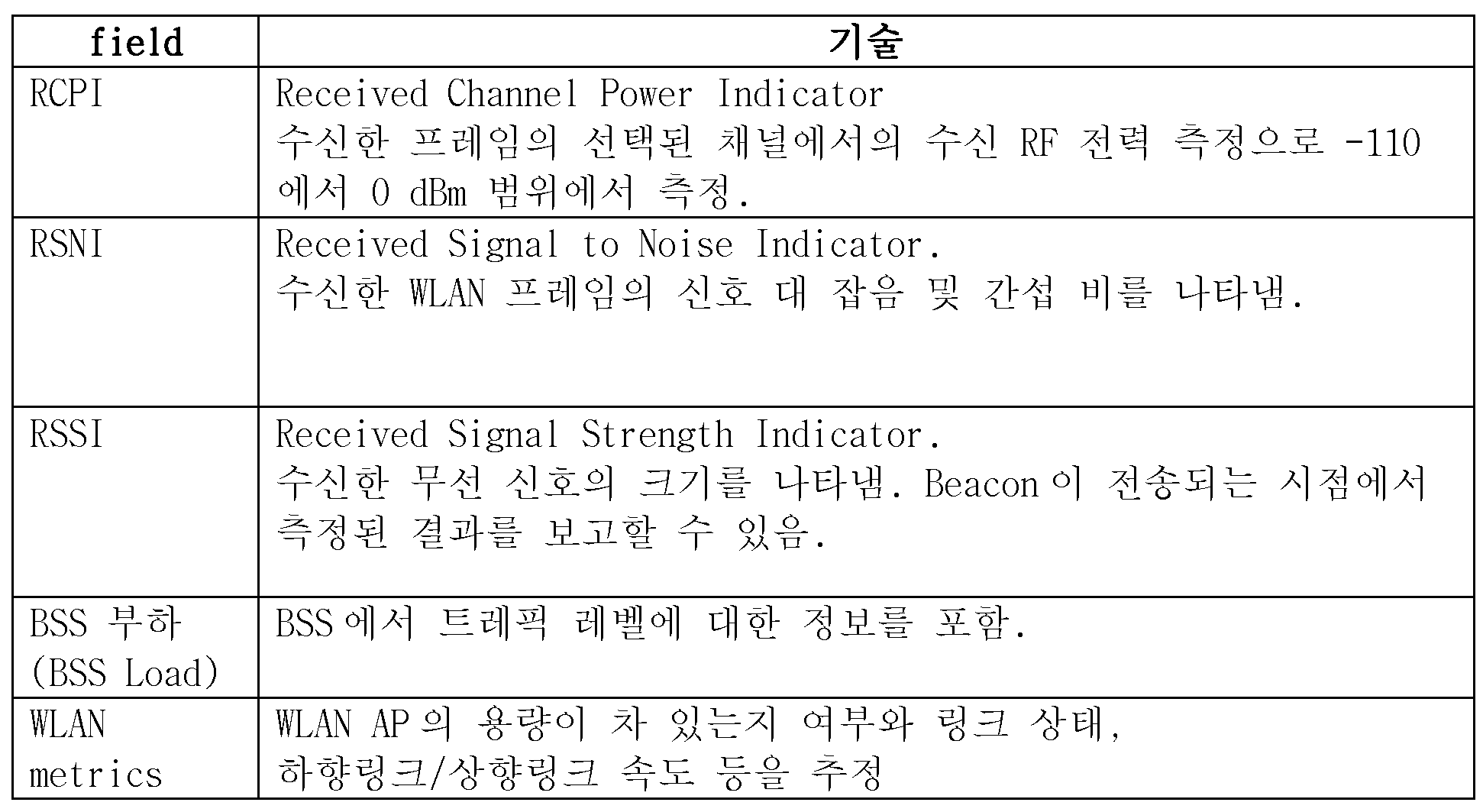
- Table 2 below is an example of fields included in the measurement configuration for the WLAN.
- the measurement setting may include information indicating an event that the WLAN should satisfy.
- the following table shows examples of events that WLAN must satisfy.
- the terminal activates the Wi-Fi service area detection (S211). If the Wi-Fi module included in the terminal is turned off, the terminal activates the Wi-Fi module and detects the Wi-Fi service area.
- the terminal detects the frequency (channel) or WLAN indicated by the measurement setting, the terminal acquires additional information on the detected frequency (channel) or WLAN. For example, information about a signal level, a channel utilization, a backhaul data rate, etc. may be obtained with respect to the detected WLAN.
- the terminal determines whether the detected WLAN satisfies the set event by using the additional information (S212).
- the terminal determines that the detected WLAN satisfies the set event, it reports the measurement result and additionally acquired information to the first network (S213).
- the following table is an example of the measurement results to report to the first network.
- the first network may request the terminal to perform a procedure for interworking with the indicated WLAN AP (eg, an authentication / association / authorization procedure) (S214). That is, the request may include information indicating at least one access point (AP) of the second network.
- a procedure for interworking with the indicated WLAN AP eg, an authentication / association / authorization procedure
- the terminal performs a procedure (authentication / combination / authorization procedure) for interworking with the indicated WLAN AP (S215).
- the terminal reports the result of the procedure for interworking (the result of the authentication / combination / authorization procedure) to the first network (S216).
- the result of performing the procedure for interworking may include whether an authentication / combination / authorization procedure for a specific WLAN AP is successfully performed, an identifier of the specific WLAN AP, and the like.
- the first network may know whether the terminal is ready to interwork with the second network.
- the first network may transmit a command for instructing interworking with the second network to the terminal (S217). At this time, the first network may transmit the command based on a result of performing the procedure for interworking.
- the first network performs interworking with the second network (S218).
- the first network performs interworking with the AP of the second network included in the result of performing the procedure for interworking.
- interworking may be performed by changing a specific bearer provided only through the first network to be provided through the second network.
- the step of transmitting a command instructing the first network to interwork with the second network may be omitted.
- FIG. 12 illustrates a method of operating a terminal according to a second embodiment to which the method of FIG. 10 is applied.
- the first network may provide a measurement configuration including information indicating whether to request to perform an authentication / combination / authorization procedure for the second network (S310). That is, unlike in FIG. 11, the measurement configuration may additionally include information indicating whether to request to perform a procedure (authentication / combination / authorization procedure) for interworking with the second network.
- the terminal activates the Wi-Fi service area detection (S311) and detects the frequency (channel) or WLAN indicated by the measurement setting, the terminal acquires additional information on the detected frequency (channel) or WLAN. For example, information about a signal level, a channel utilization, a backhaul data rate, etc. may be obtained with respect to the detected WLAN. The terminal determines whether the detected WLAN satisfies the set event by using the additional information (S312).
- the terminal When performing the authentication / combination / authorization procedure is required by the measurement setup, the terminal attempts an authentication / combination / authorization procedure for the detected WLAN AP (S314) and indicates whether the authentication / combination / authorization procedure is successful. Information may be reported together with the measurement result (S315). That is, the terminal may report the result of performing the procedure for interworking together with the measurement result to the first network.
- the first network may transmit a command for instructing interworking with the second network to the terminal (S316).
- the first network may transmit the command based on a result of performing a procedure for interworking.
- the first network performs interworking with the second network (S317).
- the first network performs interworking with the AP of the second network included in the result of performing the procedure for interworking.
- FIG. 13 to 17 illustrate an interworking architecture of a first network (LTE) and a second network (WLAN).
- LTE first network
- WLAN second network
- interworking structures may be used according to the manner in which the eNB of the LTE and the AP of the WLAN are interworked.
- FIG. 13 (a) traffic branches in a serving-gateway (S-GW).
- S-GW serving-gateway
- P-GW PDN-gateway
- FIG. 14 the traffic is branched at the base station eNB.
- the method of branching traffic at the base station is processed to the RLC layer of the first network (LTE) as shown in FIG. 15 (a), and then traffic is branched to the second network, or as shown in FIG. 15 (b), the PDCP layer. It can be a branch before it is processed in.
- traffic may be branched to the second network, or branched after being processed at the RLC layer as shown in FIG. 16 (b). Can be.
- traffic is branched after being processed at the PDCP layer of the base station.
- the RLC and MAC layers for the second network (WLAN) traffic may not be provided in the eNB.
- the present invention can be applied to other interworking structures other than the interworking structures described above.
- the first network and the second network described above may be generalized as follows. That is, the first network may be a network in which the base station operates in a licensed band, and the second network may be a network in which the base station operates in an unlicensed band.
- an EPS bearer that receives a service through a first network in which a base station operates in a licensed frequency band may be a first type bearer
- an EPS bearer that may receive service through a second network in which a base station operates in an unlicensed frequency band It may be referred to as a second type bearer.
- FIG. 18 is a block diagram illustrating a terminal in which an embodiment of the present invention can be implemented.
- the terminal 1100 includes a processor 1110, a memory 1120, and an RF unit 1130.
- the terminal 1100 may be in a state of being connected to a first network (3GPP based access network; LTE / LTE-A).
- the processor 1110 implements the proposed functions, processes, and / or methods.
- the processor 1110 may perform a procedure for interworking with a second network and report a result of performing the procedure for interworking to the first network.
- the RF unit 1130 is connected to the processor 1110 to transmit and receive a radio signal.
- the RF unit 1130 may include one or more RF units for communicating a 3GPP based access network and communicating a non-3GPP based access network.
- the processor 1110 may include an application-specific integrated circuit (ASIC), another chipset, a logic circuit, and / or a data processing device.
- ASIC application-specific integrated circuit
- the memory 1120 may include read-only memory (ROM), random access memory (RAM), flash memory, memory card, storage medium, and / or other storage device.
- the RF unit 1130 may include a baseband circuit for processing a radio signal.
- the above-described technique may be implemented as a module (process, function, etc.) for performing the above-described function.
- the module may be stored in the memory 1120 and executed by the processor 1110.
- the memory 1120 may be inside or outside the processor 1110 and may be connected to the processor 1110 by various well-known means.
Abstract
Description


Claims (11)
- 무선 통신 시스템에서 단말(User Equipment: UE)의 동작 방법에 있어서,
제1 네트워크에 연결된 상기 단말이 제2 네트워크와의 인터 워킹(interworking)을 위한 절차를 수행하고, 및
상기 인터 워킹을 위한 절차 수행의 결과를 상기 제1 네트워크로 보고하는 것을 특징으로 하는 방법. - 제 1항에 있어서,
상기 인터 워킹을 위한 절차는 상기 제2 네트워크에 대한 인증(authentication), 결합(association), 또는 인가(authorization) 절차인 것을 특징으로 하는 방법. - 제 1 항에 있어서, 상기 단말에게 상기 제2 네트워크와의 인터 워킹을 위한 절차를 수행할 것을 지시하는 요청을 상기 제1 네트워크가 전송하는 것을 특징으로 하는 방법.
- 제 3 항에 있어서, 상기 요청은 상기 제2 네트워크의 적어도 하나의 AP(access point)를 지시하는 정보를 포함하는 것을 특징으로 하는 방법.
- 제 1 항에 있어서,
상기 인터 워킹을 위한 절차 수행의 결과는,
상기 단말이 인터 워킹을 위한 절차를 성공적으로 수행했는지를 나타내는 정보와,
상기 단말이 인터 워킹을 위한 절차를 수행한 상기 제2 네트워크의 AP(access point)를 나타내는 정보를 포함하는 것을 특징으로 하는 방법. - 제 5 항에 있어서, 상기 제1 네트워크는 상기 단말에게 상기 AP와 인터 워킹할 것을 지시하는 명령을 전송하는 것을 특징으로 하는 방법.
- 제 6 항에 있어서, 상기 제1 네트워크는 상기 인터 워킹을 위한 절차 수행의 결과에 기반하여 상기 명령을 전송하는 것을 특징으로 하는 방법.
- 제 1 항에 있어서, 상기 제1 네트워크는
상기 제2 네트워크의 AP에 대한 측정 설정을 상기 단말에게 전송하는 것을 더 포함하는 것을 특징으로 하는 방법. - 제 8 항에 있어서, 상기 제2 네트워크의 AP에 대한 측정 설정은
상기 단말이 연결할 수 있는 AP를 지시하는 정보 및 상기 단말이 상기 AP에 연결하기 위해 상기 AP가 만족해야 하는 이벤트를 지시하는 정보를 포함하는 것을 특징으로 하는 방법. - 제 9 항에 있어서, 상기 제2 네트워크의 AP에 대한 측정 설정에 포함된 AP가 상기 이벤트를 만족하면, 상기 단말은 상기 제1 네트워크에게 상기 이벤트를 만족하는 AP를 보고하는 것을 특징으로 하는 방법.
- 무선 통신 시스템에서 동작하는 단말에 있어서, 상기 단말은,
무선 신호를 송신 및 수신하는 RF(Radio Frequenc) 부; 및
상기 RF부와 기능적으로 결합하여 동작하는 프로세서;를 포함하되, 상기 프로세서는,
제1 네트워크에 연결된 상기 단말이 제2 네트워크와의 인터 워킹(interworking)을 위한 절차를 수행하고, 및
상기 인터 워킹을 위한 절차 수행의 결과를 상기 제1 네트워크로 보고하는 것을 특징으로 하는 단말.
Priority Applications (2)
| Application Number | Priority Date | Filing Date | Title |
|---|---|---|---|
| US15/322,988 US10499441B2 (en) | 2014-07-02 | 2015-07-02 | Method for operating terminal in wireless communication system and terminal using same |
| KR1020167036988A KR102381818B1 (ko) | 2014-07-02 | 2015-07-02 | 무선 통신 시스템에서 단말의 동작 방법 및 이를 이용하는 단말 |
Applications Claiming Priority (2)
| Application Number | Priority Date | Filing Date | Title |
|---|---|---|---|
| US201462020372P | 2014-07-02 | 2014-07-02 | |
| US62/020,372 | 2014-07-02 |
Publications (1)
| Publication Number | Publication Date |
|---|---|
| WO2016003222A1 true WO2016003222A1 (ko) | 2016-01-07 |
Family
ID=55019663
Family Applications (1)
| Application Number | Title | Priority Date | Filing Date |
|---|---|---|---|
| PCT/KR2015/006837 WO2016003222A1 (ko) | 2014-07-02 | 2015-07-02 | 무선 통신 시스템에서 단말의 동작 방법 및 이를 이용하는 단말 |
Country Status (3)
| Country | Link |
|---|---|
| US (1) | US10499441B2 (ko) |
| KR (1) | KR102381818B1 (ko) |
| WO (1) | WO2016003222A1 (ko) |
Cited By (1)
| Publication number | Priority date | Publication date | Assignee | Title |
|---|---|---|---|---|
| WO2017200687A1 (en) * | 2016-05-18 | 2017-11-23 | Qualcomm Incorporated | Lte's wlan mobility set prioritization |
Families Citing this family (1)
| Publication number | Priority date | Publication date | Assignee | Title |
|---|---|---|---|---|
| EP3836630B1 (en) * | 2014-09-12 | 2022-10-26 | NEC Corporation | Radio station, radio terminal, and method for terminal measurement |
Citations (5)
| Publication number | Priority date | Publication date | Assignee | Title |
|---|---|---|---|---|
| WO2010095896A2 (ko) * | 2009-02-22 | 2010-08-26 | 엘지전자주식회사 | 무선 통신 시스템에서 인터 워킹 신호 전송 방법 및 장치 |
| US20130242965A1 (en) * | 2012-03-16 | 2013-09-19 | Qualcomm Incorporated | System and Method of Offloading Traffic to a Wireless Local Area Network |
| WO2013186024A1 (en) * | 2012-06-11 | 2013-12-19 | Alcatel Lucent | Interworking base station between a wireless network and a cellular network |
| WO2014069959A1 (ko) * | 2012-11-04 | 2014-05-08 | 엘지전자 주식회사 | 복수의 무선접속 기술를 지원하는 단말이 무선 링크 실패가 발생한 경우에 회복하는 방법 및 이를 위한 장치 |
| WO2014098506A1 (ko) * | 2012-12-19 | 2014-06-26 | 엘지전자 주식회사 | 다중 액세스 네트워크를 지원하는 무선 통신 시스템에서 통신 방법 및 이를 지원하는 장치 |
Family Cites Families (7)
| Publication number | Priority date | Publication date | Assignee | Title |
|---|---|---|---|---|
| US20060276190A1 (en) * | 2005-05-19 | 2006-12-07 | Interdigital Technology Corporation | Method and apparatus for implementing a handoff between radio access networks deployed under different radio access technologies |
| US9204473B2 (en) * | 2012-01-11 | 2015-12-01 | Interdigital Patent Holdings, Inc. | Method and apparatus for accelerated link setup |
| US9100852B2 (en) * | 2012-05-15 | 2015-08-04 | Futurewei Technologies, Inc. | System and method for network detection and selection |
| JP2015534355A (ja) * | 2012-09-14 | 2015-11-26 | インターデイジタル パテント ホールディングス インコーポレイテッド | 無線システムでWi−Fiオフローディングを行うためのモビリティ制御方法 |
| US8923880B2 (en) * | 2012-09-28 | 2014-12-30 | Intel Corporation | Selective joinder of user equipment with wireless cell |
| US10104540B2 (en) * | 2013-01-23 | 2018-10-16 | Qualcomm Incorporated | Determining to use multi-RAN interworking by correlating different RAN identifiers |
| US9801099B2 (en) * | 2013-05-15 | 2017-10-24 | Blackberry Limited | Method and system for use of cellular infrastructure to manage small cell access |
-
2015
- 2015-07-02 US US15/322,988 patent/US10499441B2/en active Active
- 2015-07-02 KR KR1020167036988A patent/KR102381818B1/ko active IP Right Grant
- 2015-07-02 WO PCT/KR2015/006837 patent/WO2016003222A1/ko active Application Filing
Patent Citations (5)
| Publication number | Priority date | Publication date | Assignee | Title |
|---|---|---|---|---|
| WO2010095896A2 (ko) * | 2009-02-22 | 2010-08-26 | 엘지전자주식회사 | 무선 통신 시스템에서 인터 워킹 신호 전송 방법 및 장치 |
| US20130242965A1 (en) * | 2012-03-16 | 2013-09-19 | Qualcomm Incorporated | System and Method of Offloading Traffic to a Wireless Local Area Network |
| WO2013186024A1 (en) * | 2012-06-11 | 2013-12-19 | Alcatel Lucent | Interworking base station between a wireless network and a cellular network |
| WO2014069959A1 (ko) * | 2012-11-04 | 2014-05-08 | 엘지전자 주식회사 | 복수의 무선접속 기술를 지원하는 단말이 무선 링크 실패가 발생한 경우에 회복하는 방법 및 이를 위한 장치 |
| WO2014098506A1 (ko) * | 2012-12-19 | 2014-06-26 | 엘지전자 주식회사 | 다중 액세스 네트워크를 지원하는 무선 통신 시스템에서 통신 방법 및 이를 지원하는 장치 |
Cited By (2)
| Publication number | Priority date | Publication date | Assignee | Title |
|---|---|---|---|---|
| WO2017200687A1 (en) * | 2016-05-18 | 2017-11-23 | Qualcomm Incorporated | Lte's wlan mobility set prioritization |
| US10531354B2 (en) | 2016-05-18 | 2020-01-07 | Qualcomm Incorporated | LTE's WLAN mobility set prioritization |
Also Published As
| Publication number | Publication date |
|---|---|
| KR20170027741A (ko) | 2017-03-10 |
| US10499441B2 (en) | 2019-12-03 |
| KR102381818B1 (ko) | 2022-04-01 |
| US20170142759A1 (en) | 2017-05-18 |
Similar Documents
| Publication | Publication Date | Title |
|---|---|---|
| JP6377790B2 (ja) | 多重アクセスネットワークを支援する無線通信システムにおける通信方法及びこれを支援する装置 | |
| JP6393731B2 (ja) | 多重アクセスネットワークを支援する無線通信システムにおける通信方法及びこれを支援する装置 | |
| KR101805336B1 (ko) | 무선 통신 시스템에서 트래픽 조종 방법 및 이를 이용하는 장치 | |
| KR101726197B1 (ko) | 다중 액세스 네트워크를 지원하는 무선 통신 시스템에서 선택적 트래픽 처리 방법 및 이를 지원하는 장치 | |
| WO2014119968A1 (ko) | 무선 통신 시스템에서 트래픽 조종 방법 및 이를 지원하는 장치 | |
| WO2014119966A1 (ko) | 무선 통신 시스템에서 트래픽 조종 방법 및 이를 지원하는 장치 | |
| WO2015020446A1 (ko) | 무선 통신 시스템에서 트래픽을 조종하는 방법 및 장치 | |
| WO2014098531A1 (ko) | 무선 통신 시스템에서 이동 방법 및 이를 지원하는 장치 | |
| WO2014098504A1 (ko) | 다중 액세스 네트워크를 지원하는 무선 통신 시스템에서 통신 방법 및 이를 지원하는 장치 | |
| US10404412B2 (en) | Method for interworking performed by base station and base station using same | |
| WO2014098535A1 (ko) | 무선 통신 시스템에서 통신 방법 및 이를 지원하는 장치 | |
| WO2015072752A1 (ko) | 무선 통신 시스템에서 트래픽 조종 방법 및 이를 지원하는 장치 | |
| WO2015084081A1 (ko) | 무선 통신 시스템에서 트래픽 조종 방법 및 이를 이용하는 장치 | |
| KR101790912B1 (ko) | 무선 통신 시스템에서 단말의 동작 방법 및 이를 이용하는 단말 | |
| KR102367974B1 (ko) | 무선 통신 시스템에서 단말의 인터워킹 수행 방법 및 이를 이용하는 단말 | |
| WO2016003223A1 (ko) | 무선통신 시스템에서 인터워킹을 보조하기 위한 단말의 동작 방법 및 이를 이용하는 단말 | |
| KR102381818B1 (ko) | 무선 통신 시스템에서 단말의 동작 방법 및 이를 이용하는 단말 |
Legal Events
| Date | Code | Title | Description |
|---|---|---|---|
| 121 | Ep: the epo has been informed by wipo that ep was designated in this application |
Ref document number: 15815215 Country of ref document: EP Kind code of ref document: A1 |
|
| ENP | Entry into the national phase |
Ref document number: 20167036988 Country of ref document: KR Kind code of ref document: A |
|
| WWE | Wipo information: entry into national phase |
Ref document number: 15322988 Country of ref document: US |
|
| NENP | Non-entry into the national phase |
Ref country code: DE |
|
| 122 | Ep: pct application non-entry in european phase |
Ref document number: 15815215 Country of ref document: EP Kind code of ref document: A1 |