WO2016002641A1 - プログラム開発装置及び電子制御装置 - Google Patents
プログラム開発装置及び電子制御装置 Download PDFInfo
- Publication number
- WO2016002641A1 WO2016002641A1 PCT/JP2015/068444 JP2015068444W WO2016002641A1 WO 2016002641 A1 WO2016002641 A1 WO 2016002641A1 JP 2015068444 W JP2015068444 W JP 2015068444W WO 2016002641 A1 WO2016002641 A1 WO 2016002641A1
- Authority
- WO
- WIPO (PCT)
- Prior art keywords
- program
- difference
- derived
- base
- change
- Prior art date
- Legal status (The legal status is an assumption and is not a legal conclusion. Google has not performed a legal analysis and makes no representation as to the accuracy of the status listed.)
- Ceased
Links
Images




Classifications
-
- G—PHYSICS
- G06—COMPUTING OR CALCULATING; COUNTING
- G06F—ELECTRIC DIGITAL DATA PROCESSING
- G06F9/00—Arrangements for program control, e.g. control units
- G06F9/06—Arrangements for program control, e.g. control units using stored programs, i.e. using an internal store of processing equipment to receive or retain programs
- G06F9/44—Arrangements for executing specific programs
Definitions
- the present invention relates to a program development device that supports program development and an electronic control device developed thereby.
- the embedded system has advantages in that it can realize more flexible and advanced control than the conventional mechanical mechanism and electric circuit method, and can develop many derivative products by partially changing the program.
- an electronic control device for example, an engine control device
- an input process for acquiring a sensor value such as an intake air amount or an accelerator opening an output process for driving an actuator for controlling a throttle opening or a fuel injection amount
- Communication processing for exchanging data between electronic control units is required.
- a derivative program is developed by partially changing the base program.
- a derivative program A is developed based on the base program O
- a derivative program B is subsequently developed based on the derivative program A
- a derivative program C is further developed.
- Patent Document 1 shows an example of a similarity evaluation device that calculates the similarity between program source codes.
- the similarity is calculated from the reference source code and the correlation between the plurality of target source codes.
- Patent Document 2 shows an example of a program analysis apparatus that assists in efficiently selecting software components to be reused or changed at the same time when developing a derivative product. Based on past program development results and change results, the simultaneous use relationship and the simultaneous change relationship between program parts are extracted.
- the present invention has been made to solve the above-described problems, and in the development of a program for an electronic control device, common modification of a plurality of derived programs developed by partially changing a base program
- An object of the present invention is to provide a program development support apparatus capable of extracting a part.
- the program development support apparatus includes a difference extraction unit between a base program and a derived program and a difference extraction unit between a plurality of derived programs.
- a change difference degree calculation unit that calculates a difference degree of change applied to the derived program based on a difference between the base program and the derived program and differences between the plurality of derived programs.
- FIG. 1 is a configuration diagram of a program development support device 1 according to Embodiment 1.
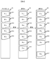
- FIG. It is a figure which shows the concept of derivative program development. It is a figure which shows the structure of the base program 21, the derivative program 31, and the derivative program 32 in derivative program development. It is a figure which shows the change content of the source code. It is a figure which shows the change content of the source code. It is a figure which shows the change content of the source code. It is a figure which shows the change content of the source code. It is a figure which shows the change content of the source code 215. It is a figure which shows the change content of the source code. It is a figure which shows the structure of the change content evaluation part.
- FIG. It is a figure which shows the concept of derivative program development. It is a figure which shows the structure of the base program 21, the derivative program 31, and the derivative program 32 in derivative program development. It is a figure which shows the change content of the source code. It is a figure which shows the change content of the source code. It is
- FIG. 10 is a diagram showing a configuration of a derived program list 1124. It is a figure which shows the structure of the source code list 1125 It is a figure which shows the base-derivative difference extraction flow performed in the base-derivative difference extraction part 1121.
- FIG. 10 is a diagram showing a derivation-derivative difference extraction flow executed in a derivation-derivative difference extraction unit 1122; It is a figure which shows the structure of the distance calculating part 1123.
- 5 is a diagram showing a configuration of change difference data 113.
- FIG. 4 is a diagram showing a configuration of change difference data 14.
- FIG. It is a figure which shows the concept of a change difference calculation system. It is a figure which shows the change difference degree of the source code.
- FIG. It is a figure which shows the change difference degree of the source code. It is a figure which shows the change difference degree of the source code 213.
- FIG. It is a figure which shows the change difference degree of the source code. It is a figure which shows the change difference degree of the source code 215.
- FIG. It is a figure which shows the base program change flow performed in the base program change part. It is a figure which shows the structure of the changed base program. It is a figure which shows the concept of the derivative program development to which this invention is applied.
- FIG. 1 is a configuration diagram of a program development support apparatus according to an embodiment of the present invention and an electronic control apparatus 7 developed thereby.
- the program development support apparatus 1 is related to development support, a base program database (DB) 2 that stores a base program that is reused for product development, a derivative program DB 3 that stores a plurality of derivative programs developed for products.
- a computer 4 that executes processing, a display device 5 that presents the execution status of the program development support device to the user, an input device 6 that is used by the user to give instructions to the program development support device, and execution on the computer 4 And a memory 10 for storing the program to be executed.
- the computer 4 includes an arithmetic processing unit such as a CPU (not shown), and the arithmetic processing unit reads a program stored in the memory 10 and executes it.
- the base program DB2 stores a base program O (original) 21 before update.
- the derivative program DB stores a derivative program A31 developed for a product based on the base program O21 before update, and a derivative program B32 developed for a product different from 31.
- the memory 10 includes a change content evaluation unit 11 that evaluates changes made to the derivation program A31 and the derivation program B32 with the base program O21 as a reference, and a change content that reflects the change content in the base program and updates the base program O22.
- a reflection unit 12, a change content evaluation unit 11, and a control unit 13 that manages operations of the change content reflection unit 12 are provided.
- the memory 10 may be an internal memory provided in the computer 4.
- the electronic control device 7 includes a memory 71 that stores an execution program obtained by converting the derivation program A31 into an execution file, and a microprocessor 72 that executes the derivation program 31 and controls the sensor 7 and the actuator 8.
- Fig. 2 is a diagram showing the concept of derivative program development.
- the derived program A31 is developed by changing the base program O21 based on a required specification for a specific product.
- the derivation program B32 is developed based on the derivation program A31.
- the derivation program C33 is developed based on the derivation program B32.
- the derivation program D34 is developed based on the derivation program C33.
- the derivative program E35 is developed based on the derivative program C33.
- FIG. 3 is a diagram showing the configuration of the base program O21, the derivation program A31, and the derivation program B32.
- the base program O21 includes a source code 211, a source code 212, a source code 213, a source code 214, and a source code 215 written in C language.
- the derived program A31 includes a source code 311 written in C language, a source code 312, a source code 313, a source code 314, a source code 315, a source code 316, and a source code 317.
- the derived program B32 includes a source code 321 written in C language, a source code 322, a source code 323, a source code 324, a source code 325, a source code 326, and a source code 327.
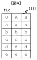
- FIG. 4 is a diagram showing a change status 2111 of the source code 211.
- the file name “f1.c” is the change status
- the “O” column indicates the source code 211
- the “A” column indicates the source code 311
- the “B” column indicates the source code 321
- “a” “ “b”, “c”, “d”, and “e” schematically indicate lines in the source code.
- the change status 2111 indicates that the source code 211 has not been changed in the development of the derived program A31 and the derived program B32 based on the base program 21.
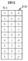
- FIG. 5 is a diagram showing a change status 2121 of the source code 212.
- the file name “f2.c” is the change status
- the “O” column indicates the source code 212
- the “A” column indicates the source code 312
- the “B” column indicates the source code 322.
- a ”,“ b ”,“ c ”, etc.) schematically indicate lines in the source code.
- the fifth line (“e”) to the eighth line (“h”) of the source code 212 are the derivation program A 31 and the derivation program.
- B32 indicates that each has been changed.
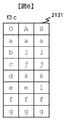
- FIG. 6 is a diagram showing a change status 2131 of the source code 213.
- the file name “f3.c” is the change status
- the “O” column indicates the source code 213
- the “A” column indicates the source code 313
- the “B” column indicates the source code 323
- the lowercase alphabet (“ a ”,“ b ”,“ c ”, etc.) schematically indicate lines in the source code.
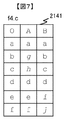
- FIG. 7 is a diagram showing a change status 2141 of the source code 214.
- the file name “f4.c” is the change status
- the “O” column indicates the source code 214
- the “A” column indicates the source code 314
- the “B” column indicates the source code 324
- lowercase letters a ”,“ b ”,“ c ”, etc. schematically indicate lines in the source code.
- the change status 2141 indicates that the second line (“b”) to the third line (“c”) of the source code 214 are changed in the development of the derived program A31 based on the base program 21.
- the change status 2141 indicates that the fifth line (“e”) to the sixth line (“f”) of the source code 214 have been changed in the development of the derived program B32 based on the base program 21. Yes.
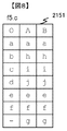
- FIG. 8 is a diagram showing a change status 2151 of the source code 215.
- the file name “f5.c” is the change status
- the “O” column indicates the source code 215
- the “A” column indicates the source code 3135
- the “B” column indicates the source code 325
- the lowercase alphabet (“a” ”,“ B ”,“ c ”, etc.) schematically indicate lines in the source code.
- the second line (“b”) to the fourth line (“d”) of the source code 215 are the derived program A31 and the derived program.
- Each change is made in B32, and the seventh line is added ("g").
- FIG. 9 is a diagram showing a change status 2161 regarding the file name “f6.c”.
- the “O” column indicates that the corresponding source code does not exist
- the “A” column indicates the source code 316
- the “B” column indicates the source code 326
- lowercase letters (“a”, “b”, “c”, etc.) ) Schematically shows a line in the source code.
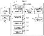
- FIG. 10 is a diagram illustrating a configuration of the change content evaluation unit 11.
- the change content evaluation unit 11 includes a difference extraction unit 112 that obtains a difference between programs based on programs stored in the base program database 2 and the derived program database 3, a change difference data 113 that stores a change difference, and a change difference
- the change difference degree calculation unit 114 for obtaining the difference degree between changes based on the change difference data 14 and the change difference degree data 14 for storing the change difference degree.
- the difference extraction unit 112 extracts a difference between a base program and a derived program, a base-derived difference extracting unit 1121, a derivation-derived difference extracting unit 1122 that extracts a difference between derived programs, and a source code
- a distance calculating unit 1123 for calculating the edit distance a derived program list storage unit 1124 for storing a list of derived programs, and a file list storage unit 1125 for storing a list of files.
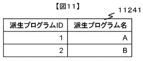
- FIG. 11 is a diagram showing a derived program list 11241 stored in the derived program list storage unit.
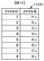
- FIG. 12 shows the file list 11251 stored in the file list storage unit.
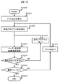
- FIG. 13 is a diagram showing a base-derivative difference extraction flow executed in the base-derivative difference extractor 1121. Processing starts from step S11210. In step S11211, the file ID is initialized. In step S11212, the ID of the derived program is initialized. In step S11213, the distance calculation unit 1123 is used to execute a distance calculation process between the base program in the analysis target file ID and the derived program ID of the analysis target derivative program ID. In step S11214, it is determined whether the derivation program to be analyzed is a final derivation program. If the derivation program is a final derivation program, the process proceeds to step S11216, and if not, the process proceeds to step S11215.
- step S11215 1 is added to the ID of the derived program, and the flow advances to step S11213.
- step S11216 it is determined whether the file to be analyzed is the final file. If the file is the final file, the process proceeds to step S11218. If the file is not the final file, the process proceeds to step S11217. In step S11217, 1 is added to the file ID, and the flow advances to step S11212. In step S11218, the process ends.
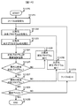
- FIG. 14 is a diagram showing a derivation program difference extraction flow executed in the derivation-derivation difference extraction unit 1122. Processing starts from step S11220.
- step S11221 the file ID is initialized.
- step S11222 the derived program ID of the comparison source is initialized.
- step S11224 the distance calculation unit 1123 is used to execute distance calculation processing between the analysis target file derivation programs.
- step S11225 it is determined whether or not the comparison target derived program ID to be analyzed is a final derived program. If it is the final derived program, the process proceeds to step S11227, and if not, the process proceeds to step S11226.
- step S11226 1 is added to the ID of the comparison destination derived program, and the process proceeds to step S11224.
- step S11227 it is determined whether or not the comparison source derivation program ID to be analyzed is a final derivation program. If it is the final derivation program, the process proceeds to step S11229; otherwise, the process proceeds to step S11228.
- step S11228, 1 is added to the ID of the comparison source derivation program, and the process proceeds to step S11223.
- step S11229 it is determined whether or not the analysis target file ID is the final file. If the file is the final file, the process proceeds to step S1122B. If not, the process proceeds to step S1122A. In step S1122A, 1 is added to the file ID, and the flow advances to step S11222. In step S1122B, the process ends.
- FIG. 15 is a diagram showing a configuration of the distance calculation unit 1123.
- the distance calculation unit 1123 includes a Levenstein distance calculation unit 11231 and a Hamming distance calculation unit 11232. In the following description, a case where a distance is calculated using the Levenshtein distance calculation unit 11231 is shown.
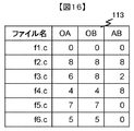
- FIG. 16 is a diagram showing the configuration of the change difference data 113.
- the file “f2.c” is changed in the base program O21, the derived program A31, and the derived program A32. Since a total of four rows are replaced, that is, deleted and added, a total of eight times between OA, the distance is 8. Since a total of 4 rows are replaced, that is, deleted and added, are performed 8 times between OBs, the distance is 8. Between AB, a total of 4 rows are replaced, that is, deleted and added, a total of 8 times, so the distance is 8.
- the file “f3.c” is changed in the base program O21, the derived program A31, and the derived program A32. Since a total of three lines of replacement between OA, that is, deletion and addition processes are performed six times, the distance is 6. Since a total of 4 rows are replaced, that is, deleted and added, are performed 8 times between OBs, the distance is 8. Between A and B, a total of one row is replaced, that is, deleted and added twice, so the distance is 2.
- the file “f4.c” is changed in the base program O21, the derived program A31, and the derived program A32. Since a total of two rows are exchanged between OA, that is, deletion and addition processing is performed four times in total, the distance is 4. Between OB, a total of two rows are replaced, that is, deleted and added four times in total, so the distance is 4. Between AB, a total of 4 rows are replaced, that is, deleted and added, a total of 8 times, so the distance is 8.
- the file “f5.c” is changed in the base program O21, the derived program A31, and the derived program A32.
- OA a total of three lines are replaced and one line is added, that is, a deletion and addition process is performed seven times, so the distance is 7.
- OB a total of three lines are replaced and one line is added, that is, deletion and addition processes are performed a total of seven times, so the distance is 7. Since it is common between AB, the distance is zero.
- the file “f6.c” does not exist in the base program O21, but is added by the derivation program A31 and the derivation program A32. Since a total of 5 lines are added between OA, the distance is 5. Since a total of 5 lines are added between OB, the distance is 5. Since it is common between AB, the distance is zero.
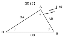
- FIG. 17 is a diagram illustrating a concept of change difference calculation processing in the change difference calculation unit 114.
- the change dissimilarity is in a triangle extending from three sides: a distance OA between the base program O21 and the derived program A31, a distance OB between the base program O21 and the derived program B32, and a distance AB between the derived program A31 and the derived program B32.
- O is the change angle of change. Based on the magnitude of this change difference degree, it is possible to extract the change contents commonly adopted in the derivation program A31 and the derivation program B32.
- the interior angle ⁇ is calculated as follows using Heron's formula.
- FIG. 18 is a conceptual diagram of the change difference calculation in the file “f1.c”. In this case, since the three sides are 0, the interior angle indicating the change difference is 0.
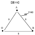
- FIG. 19 is a conceptual diagram of the change difference calculation in the file “f2.c”.
- the three-sided interior angle ⁇ is 60.
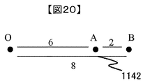
- FIG. 20 is a conceptual diagram of the change difference calculation in the file “f3.c”. In this case, the three-sided interior angle ⁇ is zero.
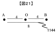
- FIG. 21 is a conceptual diagram of the change difference calculation in the file “f4.c”. In this case, the three-sided interior angle ⁇ is 180.
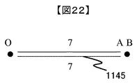
- FIG. 22 is a conceptual diagram of the change difference calculation in the file “f5.c”. In this case, the three-sided interior angle ⁇ is zero.
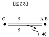
- FIG. 23 is a conceptual diagram of the change difference calculation in the file “f6.c”. In this case, the three-sided interior angle ⁇ is zero.
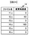
- FIG. 24 is a diagram showing a configuration of the change difference data 14 which is a calculation result of the change difference.
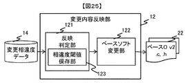
- FIG. 25 is a diagram showing the configuration of the change content reflecting unit 12.
- the change content reflection unit 12 updates the base program O21 by updating the base program O21 when the reflection process is executed, and updates the base program O22 when the reflection process is executed.
- a base program changing unit 122 for outputting, and a dissimilarity threshold storage unit 123 for storing a dissimilarity threshold at the time of reflection determination are provided.
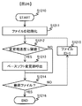
- FIG. 26 is a diagram illustrating a processing flow of the change content reflection execution determination executed in the reflection determination unit 121. Processing starts from step S1210.
- step S1211 the file ID is initialized.
- step S1212 it is determined whether or not the change difference degree of the determination target file is equal to or less than a threshold value. If it is equal to or smaller than the threshold value, the process proceeds to step S1213. Otherwise, the process proceeds to step S1214.
- step S1213, the base program changing unit 122 is called.
- step S1214 it is determined whether or not the analysis target file ID is the final file. If the file is the final file, the process proceeds to step S1216. If not, the process proceeds to step S1215. In step S1215, 1 is added to the file ID. In step S1216, the process ends.
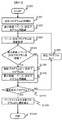
- FIG. 27 is a diagram showing a processing flow of base program change executed by the base program change unit 122.
- a processing target file ID is designated. Processing starts from step S1220.
- step S1221 the derived program ID to be analyzed is initialized.
- step S1222 the distance between the base program and the derived program in the processing target file is substituted from the change difference data 113 into the minimum distance.
- step S1223 the distance between the base program and the derived program in the processing target file is acquired from the change difference data 113.
- step S1225 the derived program ID is substituted for the update program ID.
- step S1226 the base-derived distance is substituted for the minimum distance.
- step S1227 it is determined whether or not the derived program ID to be analyzed is final. If so, the process proceeds to step S1229; otherwise, the process proceeds to step S1228.
- step S1228 1 is added to the derived program ID.
- step S1229 the base program file is replaced with the update program ID file. The process ends in step S122A.
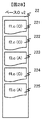
- FIG. 28 is a diagram showing the configuration of the updated base program O22. It is an update example when the change difference threshold value stored in the change difference threshold storage unit is set to 0.
- the updated base program O22 includes a file “f1.c” 221, a file “f2.c” 222, a file “f3.c” 223, a file “f4.c” 224, and a file “f5.c” 225.
- the file “f1.c” 221 has not been updated from “f1.c” of the base program O21. This is because there is no program update between any files.
- the file “f2.c” 222 has not been updated from “f2.c” of the base program O21.
- the change difference degree is larger than the change difference degree threshold, and the contents changed in each of the derivation program A31 and the derivation program B32 are changes related to functions required for each derivation program, and are not determined as common change contents. It is.
- the file “f3.c” 223 is updated to “f3.c” of the derivation program A31. This is because the content that is equal to or less than the change difference threshold and is changed in each of the derivation program A31 and the derivation program B32 is a change related to an improved portion required in both derivation programs, and is determined to be common change content.
- the file “f4.c” 224 is not updated from “f4.c” of the base program O21. This is because the change dissimilarity is larger than the change dissimilarity threshold and is not determined as common change contents.
- the file “f5.c” 225 is updated to “f5.c” of the derived program A31.
- the file “f6.c” is deleted.
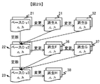
- FIG. 29 shows a base program update method and a derived program development method to which the present invention is applied.
- the derived program A31 is developed by changing the base program O21 based on a required specification for a specific product.
- the derivation program B32 is developed based on the derivation program A31.
- the base program O22 is updated to reflect changes common to the derivation program A31 and the derivation program A32.
- the derivative program F36 is developed based on the base program O22.
- the derivation program G37 is developed based on the derivation program F36.
- the base program O23 is updated to reflect changes common to the derivation program F36 and the derivation program G37.
- the derived program H38 is developed based on the base program O23.
- the change content evaluation unit 11 performs changes commonly adopted in a plurality of derived programs based on the changed content of the base program O21, the derived program A31, and the derived program B32. It is possible to extract and update the base program O. Further, the change content evaluation unit 11 automatically calculates the difference between the base program O21 and the derived program A31, the difference between the base program O21 and the derived program B32, and the difference between the derived program A31 and the derived program B32 by the difference extracting unit 112. Therefore, based on these differences, it can be used to extract changes that are commonly adopted by a plurality of derived programs.
Landscapes
- Engineering & Computer Science (AREA)
- Software Systems (AREA)
- Theoretical Computer Science (AREA)
- Physics & Mathematics (AREA)
- General Engineering & Computer Science (AREA)
- General Physics & Mathematics (AREA)
- Stored Programmes (AREA)
Abstract
複数の電子制御装置に利用されるベースプログラムの開発を支援するプログラム開発支援装置に関し、派生プログラム開発において実施された共通的な変更内容を抽出し、ベースプログラムを更新することができる。 本発明に係るプログラム開発装置は、ベースプログラムと派生プログラムとの差分抽出部と、複数の派生プログラム間の差分抽出部を有する。また、ベースプログラムと派生プログラムとの差分と、複数の派生プログラム間の差分とに基づいて、派生プログラムに加えられた変更の相違度を演算する変更相違度演算部を有する。
Description
本発明は、プログラムの開発を支援するプログラム開発装置およびそれにより開発した電子制御装置に関するものである。
自動車、建設機械等の技術分野では、いわゆる組込みシステムによって制御対象を制御する、電子制御装置が用いられている。組込みシステムは、従来の機械的機構や電気回路による方式に比べて柔軟かつ高度な制御が実現できること、プログラムの部分的な変更によって多くの派生製品を開発できることが利点として挙げられる。
このような電子制御装置、例えばエンジン制御装置では、吸入空気量やアクセル開度などのセンサ値を取得する入力処理や、スロットル開度や燃料噴射量を制御するアクチュエータを駆動するための出力処理、電子制御装置間でのデータ交換を行うための通信処理が必要となる。その一方で、電子制御装置に求められる機能がエンジン、車種ごとに異なるため、ベースとなるプログラムを部分的に変更することによって、派生プログラムを開発する。
その一方で、車種の増加や、車両販売先地域の増加に伴って、派生プログラムの数が増大し、ベースプログラムの更新が困難になるという課題がある。
例えばベースプログラムOに基づいて派生プログラムAを、続いて派生プログラムAに基づいて派生プログラムBを開発した場合に、さらに派生プログラムCを開発する場合を考える。
派生プログラムAで実現されている新規機能を派生プログラムCで利用したい場合、派生プログラムCをベースプログラムOから開発しようとすると、派生プログラムAで実現済みの新規機能をベースプログラムOに追加するための再開発をしなければならず、開発効率の低下を招くという課題がある。
一方で、派生プログラムAを改造して派生プログラムCを開発しようとすると、派生プログラムA固有の要求を実現している部分をベースプログラムO相当に戻さなければならず、やはり開発効率の低下を招くという課題がある。
すなわち、ベースプログラムに基づいた派生プログラムの開発において、ベースプログラムに追加すべき、各派生プログラムに共通的な変更箇所を抽出するとともに、共通的な変更箇所を反映してベースプログラムを更新することが必要不可欠である。
下記特許文献1には、プログラムのソースコード間の類似度を算出する類似度評価装置の例が示されている。参照ソースコードと複数の対象ソースコードの相関とから類似度を算出する。
下記特許文献2には、派生製品開発時に、同時に再利用または変更すべきソフト部品を効率的に選択できるよう支援するプログラム分析装置の例が示されている。過去のプログラムの開発実績及び変更実績に基づいて、プログラム部品間の同時利用関係および同時変更関係を抽出する。
上記特許文献1に記載された技術では、参照ソースコードと複数の対象ソースコードとの類似性は評価できるが、対象ソースコード間での類似性を評価することができない。したがって、ベースプログラムに基づいた派生プログラムの開発への適用を考えた場合に、各派生プログラム同士で共通的な変更箇所と、共通しない変更箇所とを区別して抽出することが出来ない。
上記特許文献2に記載された技術では、プログラム部品間での変更の同時発生は評価できるが、あるプログラム部品における複数の派生製品を横断しての変更の内容の共通性を評価できない。
本発明は、上記のような課題を解決するためになされたものであり、電子制御装置向けプログラムの開発において、ベースとなるプログラムを部分的に変更して開発された複数の派生プログラムの共通変更箇所を抽出可能なプログラム開発支援装置を提供することを目的とする。
本発明に係るプログラム開発支援装置は、ベースプログラムと派生プログラムとの差分抽出部と、複数の派生プログラム同士の差分抽出部を有する。また、ベースプログラムと派生プログラムとの差分と、複数の派生プログラム同士の差分とに基づいて、派生プログラムに加えられた変更の相違度を演算する変更相違度演算部を有する。
本発明に係るプログラム開発支援装置によれば、派生プログラム開発によって実現された共通的な変更内容を抽出し、ベースプログラムを更新することができる。
図1は、本発明の実施の形態に係るプログラム開発支援装置及びそれにより開発した電子制御装置7の構成図である。
プログラム開発支援装置1は、製品開発に再利用されるベースプログラムを保存するベースプログラムデータベース(DB)2と、製品向けに開発された複数の派生プログラムを保存する派生プログラムDB3と、開発支援にかかわる処理を実行するコンピュータ4と、プログラム開発支援装置の実行状況をユーザに提示する表示装置5と、プログラム開発支援装置に対してユーザが指示を与えるために利用する入力装置6と、コンピュータ4に実行されるプログラムを記憶するメモリ10とを備える。コンピュータ4は図示しないCPU等の演算処理装置を備え、演算処理装置はメモリ10に格納されたプログラムを読み込み、実行処理する。
ベースプログラムDB2は、更新前のベースプログラムO(オリジナル)21を格納している。
派生プログラムDBは更新前のベースプログラムO21に基づいて有る製品向けに開発された派生プログラムA31と、31とは異なる製品向けに開発された派生プログラムB32と、を格納している。
メモリ10は、ベースプログラムO21を基準として派生プログラムA31と派生プログラムB32とに加えられた変更内容を評価する変更内容評価部11と、変更内容をベースプログラムに反映しベースプログラムO22に更新する変更内容反映部12と、前記変更内容評価部11と変更内容反映部12の動作を管理する制御部13とを備える。メモリ10はコンピュータ4内部に供えられた内部メモリであってもよい。
電子制御装置7は、派生プログラムA31を実行ファイルに変換した実行プログラムを記憶するメモリ71と、派生プログラム31を実行し、センサ7およびアクチュエータ8を制御するマイクロプロセッサ72とを備える。
図2は、派生プログラム開発の概念を示す図である。派生プログラムA31は特定の製品向けの要求仕様に基づいて、ベースプログラムO21を変更して開発される。派生プログラムB32は派生プログラムA31に基づいて開発される。派生プログラムC33は派生プログラムB32に基づいて開発される。派生プログラムD34は派生プログラムC33に基づいて開発される。派生プログラムE35は派生プログラムC33に基づいて開発される。
派生プログラムA31で実現されている新規機能を派生プログラムC33で利用したい場合、派生プログラムC33をベースプログラムO21から開発しようとすると、派生プログラムA31で実現済みの新規機能を再開発しなければならず、開発効率の低下を招くという課題がある。
一方で、図2に示すように派生プログラムA31を改造して派生プログラムC33を開発しようとすると、派生プログラムA31固有の要求を実現しており、派生プログラムC33では要求されない部分をベースプログラムO21相当に戻さなければならず、やはり開発効率の低下を招くという課題がある。
図3はベースプログラムO21、派生プログラムA31、派生プログラムB32の構成を示す図である。
ベースプログラムO21はC言語で記述されたソースコード211と、ソースコード212と、ソースコード213と、ソースコード214と、ソースコード215とで構成される。
派生プログラムA31はC言語で記述されたソースコード311と、ソースコード312と、ソースコード313と、ソースコード314と、ソースコード315と、ソースコード316と、ソースコード317とで構成される。
派生プログラムB32はC言語で記述されたソースコード321と、ソースコード322と、ソースコード323と、ソースコード324と、ソースコード325と、ソースコード326と、ソースコード327とで構成される。
図4は、ソースコード211の変更状況2111を示す図である。ファイル名“f1.c”に関する変更状況であり、「O」列はソースコード211を、「A」列はソースコード311を、「B」列はソースコード321を示しており、「a」「b」「c」「d」「e」はソースコード中の行を模式的に示している。
変更状況2111は、ベースプログラム21に基づいた派生プログラムA31および派生プログラムB32の開発において、ソースコード211は変更されていないことを示している。
図5は、ソースコード212の変更状況2121を示す図である。ファイル名“f2.c”に関する変更状況であり、「O」列はソースコード212を、「A」列はソースコード312を、「B」列はソースコード322を示しており、アルファベット小文字(「a」「b」「c」など)はソースコード中の行を模式的に示している。
変更状況2121は、ベースプログラム21に基づいた派生プログラムA31および派生プログラムB32の開発において、ソースコード212の5行目(「e」)~8行目(「h」)が派生プログラムA31および派生プログラムB32でそれぞれ変更されていることを示している。
図6は、ソースコード213の変更状況2131を示す図である。ファイル名“f3.c”に関する変更状況であり、「O」列はソースコード213を、「A」列はソースコード313を、「B」列はソースコード323を示しており、アルファベット小文字(「a」「b」「c」など)はソースコード中の行を模式的に示している。
変更状況2131は、ベースプログラム21に基づいた派生プログラムA31および派生プログラムB32の開発において、ソースコード213の2行目(「b」)~5行目(「e」)が派生プログラムA31および派生プログラムB32でそれぞれ変更されていることを示している。(5行目はBのみ変更)
図7は、ソースコード214の変更状況2141を示す図である。ファイル名“f4.c”に関する変更状況であり、「O」列はソースコード214を、「A」列はソースコード314を、「B」列はソースコード324を示しており、アルファベット小文字(「a」「b」「c」など)はソースコード中の行を模式的に示している。
図7は、ソースコード214の変更状況2141を示す図である。ファイル名“f4.c”に関する変更状況であり、「O」列はソースコード214を、「A」列はソースコード314を、「B」列はソースコード324を示しており、アルファベット小文字(「a」「b」「c」など)はソースコード中の行を模式的に示している。
変更状況2141は、ベースプログラム21に基づいた派生プログラムA31の開発において、ソースコード214の2行目(「b」)~3行目(「c」)が変更されていることを示している。また、変更状況2141は、ベースプログラム21に基づいた派生プログラムB32の開発において、ソースコード214の5行目(「e」)~6行目(「f」)が変更されていることを示している。
図8は、ソースコード215の変更状況2151を示す図である。ファイル名“f5.c”に関する変更状況であり、「O」列はソースコード215を、「A」列はソースコード3135、「B」列はソースコード325を示しており、アルファベット小文字(「a」「b」「c」など)はソースコード中の行を模式的に示している。
変更状況2151は、ベースプログラム21に基づいた派生プログラムA31および派生プログラムB32の開発において、ソースコード215の2行目(「b」)~4行目(「d」)が派生プログラムA31および派生プログラムB32でそれぞれ変更されとともに、7行目が追加(「g」)されていることを示している。
図9は、ファイル名“f6.c”に関する変更状況2161を示す図である。「O」列は対応するソースコードが存在しないことを、「A」列はソースコード316、「B」列はソースコード326を示しており、アルファベット小文字(「a」「b」「c」など)はソースコード中の行を模式的に示している。
変更状況2161は、ベースプログラム21に基づいた派生プログラムA31および派生プログラムB32の開発において、ベースプログラム21には存在しなかったソースコード“f6.c”が派生プログラムA31および派生プログラムB32でそれぞれ追加されていることを示している。
図10は、変更内容評価部11の構成を示す図である。変更内容評価部11は、ベースプログラムデータベース2と派生プログラムデータベース3それぞれに格納されたプログラムに基づいてプログラム間の差分を求める差分抽出部112と、変更差分を保存する変更差分データ113と、変更差分に基づいて変更間相違度を求める変更相違度演算部114と、変更相違度を保存する変更相違度データ14とを備える。
差分抽出部112は、ベースプログラムと派生プログラムとの間の差分を抽出するベース-派生間差分抽出部1121と、派生プログラム間の差分を抽出する派生―派生間差分抽出部1122と、ソースコード間の編集距離を演算する距離演算部1123と、派生プログラムの一覧を記憶する派生プログラムリスト記憶部1124と、ファイルの一覧を記憶するファイルリスト記憶部1125とを備える。
図11は、派生プログラムリスト記憶部に記憶される派生プログラムリスト11241を示す図である。
図12は、ファイルリスト記憶部に記憶されるファイルリスト11251を示す図である。
図13は、ベース-派生間差分抽出部1121において実行されるベース-派生間差分抽出フローを示す図である。ステップS11210から処理が開始される。ステップS11211にてファイルのIDが初期化される。ステップS11212にて派生プログラムのIDが初期化される。ステップS11213にて距離演算部1123を用いて分析対象のファイルIDにおけるベースプログラムと分析対象の派生プログラムIDの派生プログラムとの距離演算処理を実行する。ステップS11214にて分析対象の派生プログラムが最終派生プログラムか否かを判定し、最終派生プログラムの場合にはステップS11216に進み、最終派生プログラムでない場合にはステップS11215に進む。ステップS11215では派生プログラムのIDに1を加算し、ステップS11213に進む。ステップS11216では分析対象のファイルが最終ファイルか否かを判定し、最終ファイルの場合にはステップS11218に進み、最終ファイルでない場合にはステップS11217に進む。ステップS11217ではファイルIDに1を加算し、ステップS11212に進む。ステップS11218では処理を終了する。
図14は、派生―派生間差分抽出部1122において実行される派生プログラム間差分抽出フローを示す図である。ステップS11220から処理が開始される。ステップS11221にてファイルIDを初期化する。ステップS11222にて比較元の派生プログラムIDを初期化する。ステップS11223にて比較先の派生プログラムIDを初期化する。ステップS11224にて距離演算部1123を用いて分析対象ファイルの派生プログラム間の距離演算処理を実行する。ステップS11225にて分析対象の比較先派生プログラムIDが最終派生プログラムか否かを判定し、最終派生プログラムの場合にはステップS11227に進み、そうでない場合にはステップS11226に進む。ステップS11226では比較先派生プログラムのIDに1を加算し、ステップS11224に進む。ステップS11227では分析対象の比較元派生プログラムIDが最終派生プログラムか否かを判定し、最終派生プログラムの場合にはステップS11229に進み、そうでない場合にはステップS11228に進む。ステップS11228では比較元派生プログラムのIDに1を加算し、ステップS11223に進む。ステップS11229では分析対象ファイルIDが最終ファイルか否かを判定し、最終ファイルの場合にはステップS1122Bに進み、そうでない場合にはステップS1122Aに進む。ステップS1122AではファイルIDに1を加算し、ステップS11222に進む。ステップS1122Bで処理を終了する。
図15は距離演算部1123の構成を示す図である。距離演算部1123はレーベンシュタイン距離演算部11231とハミング距離演算部11232とを備える。以降の説明では、レーベンシュタイン距離演算部11231を用いて距離の演算を行った場合を示す。
図16は変更差分データ113の構成を示す図である。
図4に示す通り、ファイル“f1.c”は、ベースプログラムO21と派生プログラムA31と派生プログラムA32とで変更はないため、O-A間、O-B間、A-B間の編集距離はすべて0となる。
図5に示す通り、ファイル“f2.c”は、ベースプログラムO21と派生プログラムA31と派生プログラムA32とで変更されている。O-A間では計4行の置換、すなわち削除および追加処理が計8回行われているため、距離は8となる。O-B間では計4行の置換、すなわち削除および追加処理が計8回行われているため、距離は8となる。A-B間では計4行の置換、すなわち削除および追加処理が計8回行われているため、距離は8となる。
図6に示す通り、ファイル“f3.c”は、ベースプログラムO21と派生プログラムA31と派生プログラムA32とで変更されている。O-A間では計3行の置換、すなわち削除および追加処理が計6回行われているため、距離は6となる。O-B間では計4行の置換、すなわち削除および追加処理が計8回行われているため、距離は8となる。A-B間では計1行の置換、すなわち削除および追加処理が計2回行われているため、距離は2となる。
図7に示す通り、ファイル“f4.c”は、ベースプログラムO21と派生プログラムA31と派生プログラムA32とで変更されている。O-A間では計2行の置換、すなわち削除および追加処理が計4回行われているため、距離は4となる。O-B間では計2行の置換、すなわち削除および追加処理が計4回行われているため、距離は4となる。A-B間では計4行の置換、すなわち削除および追加処理が計8回行われているため、距離は8となる。
図8に示す通り、ファイル“f5.c”は、ベースプログラムO21と派生プログラムA31と派生プログラムA32とで変更されている。O-A間では計3行の置換と1行の追加、すなわち削除および追加処理が計7回行われているため、距離は7となる。O-B間では計3行の置換と1行の追加、すなわち削除および追加処理が計7回行われているため、距離は7となる。A-B間では共通のため、距離は0となる。
図9に示す通り、ファイル“f6.c”は、ベースプログラムO21には存在せず、派生プログラムA31と派生プログラムA32とで追加されている。O-A間では計5行の追加が行われているため、距離は5となる。O-B間では計5行の追加が行われているため、距離は5となる。A-B間では共通のため、距離は0となる。
図17は、変更相違度演算部114における変更相違度演算処理の概念を示す図である。変更相違度は、ベースプログラムO21と派生プログラムA31との距離OAと、ベースプログラムO21と派生プログラムB32との距離OBと、派生プログラムA31と派生プログラムB32との距離ABとの3辺が張る三角形における、Oの内角γを変更相違度とする。この変更相違度の大きさに基づいて、派生プログラムA31と派生プログラムB32とで共通的に採用された変更内容を抽出することが出来る。
内角γはHeronの公式を用い、以下のように求める。
s=(OA+OB+AB)/2 …(式1)
S=√(s(s-OA)(s-OB)(s-AB)) …(式2)
(OB ≧ OA、ABの場合)
h=(2S)/OB、γ=arcsin(h/OA)…(式3)
(AB ≧OA、ABの場合)
h=(2S)/AB、γ=180-arcsin(h/OA)-arcsin(h/OB) …(式4)
(OA ≧ OB、ABの場合)
h=(2S)/OA、γ=arcsin(h/OB)…(式5)
図18はファイル“f1.c”における変更相違度演算の概念図である。この場合は、三辺ともに0のため、変更相違度を示す内角は0となる。
S=√(s(s-OA)(s-OB)(s-AB)) …(式2)
(OB ≧ OA、ABの場合)
h=(2S)/OB、γ=arcsin(h/OA)…(式3)
(AB ≧OA、ABの場合)
h=(2S)/AB、γ=180-arcsin(h/OA)-arcsin(h/OB) …(式4)
(OA ≧ OB、ABの場合)
h=(2S)/OA、γ=arcsin(h/OB)…(式5)
図18はファイル“f1.c”における変更相違度演算の概念図である。この場合は、三辺ともに0のため、変更相違度を示す内角は0となる。
図19はファイル“f2.c”における変更相違度演算の概念図である。この場合は、三辺内角γは60となる。
図20はファイル“f3.c”における変更相違度演算の概念図である。この場合は、三辺内角γは0となる。
図21はファイル“f4.c”における変更相違度演算の概念図である。この場合は、三辺内角γは180となる。
図22はファイル“f5.c”における変更相違度演算の概念図である。この場合は、三辺内角γは0となる。
図23はファイル“f6.c”における変更相違度演算の概念図である。この場合は、三辺内角γは0となる。
図24は変更相違度の計算結果である変更相違度データ14の構成を示す図である。
図25は変更内容反映部12の構成を示す図である。変更内容反映部12は、変更相違度データ14に基づいて反映処理の実施/不実施を判定する反映判定部121と、反映処理実施の際にはベースプログラムO21を更新して新しいベースプログラムO22を出力するベースプログラム変更部122と、反映判定時の相違度閾値を記憶する相違度閾値保存部123とを備える。
図26は反映判定部121において実行される変更内容反映実施判定の処理フローを示す図である。ステップS1210から処理が開始される。ステップS1211においてファイルIDが初期化される。ステップS1212において判定対象ファイルの変更相違度が閾値以下であるか否かが判定される。閾値以下の場合にはステップS1213に進み、そうでない場合にはステップS1214に進む。ステップS1213ではベースプログラム変更部122を呼び出す。ステップS1214では分析対象ファイルIDが最終ファイルか否かを判定し、最終ファイルの場合はステップS1216に進み、そうでない場合にはステップS1215に進む。ステップS1215ではファイルIDに1を加算する。ステップS1216で処理を終了する。
図27はベースプログラム変更部122において実行されるベースプログラム変更の処理フローを示す図である。図26のステップS1213から呼び出される際に、処理対象ファイルIDが指定される。ステップS1220から処理が開始される。ステップS1221で分析対象の派生プログラムIDが初期化される。ステップS1222で最小距離に変更差分データ113から処理対象ファイルにおけるベースプログラムと派生プログラムとの距離を代入する。ステップS1223で変更差分データ113から処理対象ファイルにおけるベースプログラムと派生プログラムとの距離を取得する。ステップS1224において、最小距離とベース-派生間距離とのいずれかが大きいかを判定する。最小距離のほうが大きい場合にはステップS1225に進み、そうでない場合にはステップS1227に進む。ステップS1225では更新プログラムIDに派生プログラムIDを代入する。ステップS1226では最小距離にベース-派生間距離を代入する。ステップS1227では分析対象の派生プログラムIDが最終であるか否かを判定する。最終の場合にはステップS1229に進み、そうでない場合にはステップS1228に進む。ステップS1228では派生プログラムIDに1を加算する。ステップS1229ではベースプログラムのファイルを更新プログラムIDのファイルに置換する。ステップS122Aで処理を終了する。
図28は更新されたベースプログラムO22の構成を示す図である。変更相違度閾値保存部に保存された変更相違度閾値を0とした場合の更新例である。更新されたベースプログラムO22はファイル“f1.c”221と、ファイル“f2.c”222と、ファイル“f3.c”223と、ファイル“f4.c”224と、ファイル“f5.c”225とを備える。ファイル“f1.c”221はベースプログラムO21の“f1.c”から更新されていない。いずれのファイル間でもプログラムの更新が無いからである。ファイル“f2.c”222はベースプログラムO21の“f2.c”から更新されていない。変更相違度閾値よりも変更相違度が大きく、派生プログラムA31と派生プラグラムB32それぞれで変更された内容は、それぞれの派生プログラム固有に要求される機能に関する変更であり、共通の変更内容と判断しないからである。ファイル“f3.c”223は派生プログラムA31の“f3.c”に更新されている。変更相違度閾値以下であり、派生プログラムA31と派生プラグラムB32それぞれで変更された内容は、それぞれの派生プログラム両方で要求される改良部分に関する変更であり、共通の変更内容と判断するからである。ファイル“f4.c”224はベースプログラムO21の“f4.c”から更新されていない。変更相違度閾値よりも変更相違度が大きく、共通の変更内容と判断しないからである。ファイル“f5.c”225は派生プログラムA31の“f5.c”に更新される。ファイル“f6.c”は削除される。
上述の例では、ファイル“f6.c”を削除する例を示したが、ファイル“f6.c”の追加に関する変更相違度は変更依存閾値以下であり、共通の変更内容を考えることもでき、ベースプログラムO22に追加されるようにしてもよい。
図29は、本発明を適用したベースプログラムの更新方法及び派生プログラムの開発方法である。派生プログラムA31は特定の製品向けの要求仕様に基づいて、ベースプログラムO21を変更して開発される。派生プログラムB32は派生プログラムA31に基づいて開発される。ベースプログラムO22は、本発明に基づいて、派生プログラムA31と派生プログラムA32に共通の変更内容を反映して更新される。派生プログラムF36はベースプログラムO22に基づいて開発される。派生プログラムG37は派生プログラムF36に基づいて開発される。ベースプログラムO23は、本発明に基づいて、派生プログラムF36と派生プログラムG37に共通の変更内容を反映して更新される。派生プログラムH38はベースプログラムO23に基づいて開発される。
以上のように、本実施の形態において、変更内容評価部11は、ベースプログラムO21と派生プログラムA31と派生プログラムB32との変更内容に基づいて、複数の派生プログラムに共通的に採用された変更を抽出し、ベースプログラムOを更新することが可能になる。また、変更内容評価部11は、差分抽出部112により、ベースプログラムO21と派生プログラムA31との差分、ベースプログラムO21と派生プログラムB32との差分、派生プログラムA31と派生プログラムB32との差分をそれぞれ自動的に抽出できるので、これらの差分に基づいて複数の派生プログラムに共通的に採用された変更内容の抽出に用いることが出来る。
1:プログラム開発支援装置、11:変更内容評価部、12:変更内容反映部、2:ベースプログラムDB、3:派生プログラムDB
Claims (11)
- メモリと、
前記メモリに格納されたソフトウェアを実行する演算処理装置と、を有し、
前記メモリは、外部電子制御装置向けに開発されたベースプログラムと前記ベースプログラムからそれぞれ変更された複数の派生プログラムとに基づいて、プログラム間の差分を抽出するための差分抽出部を格納し、
前記差分抽出部は、前記ベースプログラムと前記複数の派生プログラムとの差分を抽出するベース・派生間差分抽出部と、
前記複数の派生プログラム同士の差分を抽出する派生・派生間差分抽出部と、を有することを特徴とするプログラム開発装置。 - 前記差分抽出部は、前記ベースプログラムおよび前記複数の派生プログラムに基づいて、プログラム間差分を数値化して編集距離として演算する距離演算部を有する
ことを特徴とする請求項1記載のプログラム開発装置。 - 前記メモリは、前記プログラム間差分に基づいて、前記ベースプログラムと複数の前記派生プログラム同士の変更相違度を算出する変更相違度演算部を格納することを特徴とする請求項2記載のプログラム開発装置。
- 前記変更相違度演算部は、前記ベースプログラムと前記複数の派生プログラム中の第1の前記派生プログラムとの編集距離と、前記ベースプログラムと前記複数の派生プログラム中の第2の前記派生プログラムとの編集距離と、前記第1の前記派生プログラムと前記第2の前記派生プログラムとの編集距離と、を三辺とする三角形において、前記ベースプログラムを頂点とする内角の角度を変更相違度として求めることを特徴とする請求項3記載のプログラム開発装置。
- 前記距離演算部は、少なくとも前記編集距離をレーベンシュタイン距離として求めるレーベンシュタイン距離演算部と、
前記編集距離をハミング距離として求めるハミング距離演算部と、のうち少なくともいずれか一つを有することを特徴とする請求項2記載のプログラム開発装置。 - 前記変更相違度と前記ベースプログラムと前記複数の派生プログラムとに基づいて、前記ベースプログラムの更新を行う変更内容反映部を有することを特徴とする請求項3記載のプログラム開発装置。
- 前記変更内容反映部は、前記変更相違度に基づいてベースプログラムを変更するか否かを判定する反映判定部と、前記編集距離と前記ベースプログラムと前記複数の派生プログラムとに基づいて前記ベースプログラムの変更を実施するベースソフト変更部と、を有することを特徴とする請求項6記載のプログラム開発装置。
- 前記反映判定部は、前記変更相違度と相違度閾値の大小関係に基づいて、ベースプログラムを変更するか否かを判定することを特徴とする
ことを特徴とする請求項7記載のプログラム開発装置及びそれにより開発されたプログラムを搭載する制御装置。 - 前記変更内容反映部は、前記相違度閾値を保存する相違度閾値保存部を有することを特徴とする請求項8記載のプログラム開発装置。
- 前記ベースソフト変更部は、前記ベースプログラムと、前記複数の派生ソフトウェアの中で編集距離が最も小さい派生プログラムとを置換することを特徴とする請求項9記載のプログラム開発装置。
- 請求項3記載のプログラム開発装置によって開発されたプログラムを搭載する電子制御装置。
Applications Claiming Priority (2)
| Application Number | Priority Date | Filing Date | Title |
|---|---|---|---|
| JP2014133500A JP6286297B2 (ja) | 2014-06-30 | 2014-06-30 | プログラム開発装置 |
| JP2014-133500 | 2014-06-30 |
Publications (1)
| Publication Number | Publication Date |
|---|---|
| WO2016002641A1 true WO2016002641A1 (ja) | 2016-01-07 |
Family
ID=55019180
Family Applications (1)
| Application Number | Title | Priority Date | Filing Date |
|---|---|---|---|
| PCT/JP2015/068444 Ceased WO2016002641A1 (ja) | 2014-06-30 | 2015-06-26 | プログラム開発装置及び電子制御装置 |
Country Status (2)
| Country | Link |
|---|---|
| JP (1) | JP6286297B2 (ja) |
| WO (1) | WO2016002641A1 (ja) |
Citations (1)
| Publication number | Priority date | Publication date | Assignee | Title |
|---|---|---|---|---|
| WO2013088461A1 (ja) * | 2011-12-12 | 2013-06-20 | 株式会社 日立製作所 | ソフトウェア解析プログラム、および、ソフトウェア解析システム |
-
2014
- 2014-06-30 JP JP2014133500A patent/JP6286297B2/ja active Active
-
2015
- 2015-06-26 WO PCT/JP2015/068444 patent/WO2016002641A1/ja not_active Ceased
Patent Citations (1)
| Publication number | Priority date | Publication date | Assignee | Title |
|---|---|---|---|---|
| WO2013088461A1 (ja) * | 2011-12-12 | 2013-06-20 | 株式会社 日立製作所 | ソフトウェア解析プログラム、および、ソフトウェア解析システム |
Non-Patent Citations (3)
| Title |
|---|
| MAI IWAMOTO: "Token-based Code Clone Detection Technique in a Student's Programming Exercise", IPSJ SIG NOTES, 15 October 2012 (2012-10-15), pages 1 - 8, XP032311772 * |
| TAKASHI OKAMOTO, GIT POCKET REFERENCE, 10 August 2012 (2012-08-10), pages 165 - 169 * |
| TETSUO YAMAMOTO: "Similarity of Software System and Its Measurement Tool SMMT", THE TRANSACTIONS OF THE INSTITUTE OF ELECTRONICS, INFORMATION AND COMMUNICATION ENGINEERS, vol. J85-D-I, 1 June 2002 (2002-06-01), pages 503 - 511 * |
Also Published As
| Publication number | Publication date |
|---|---|
| JP2016012238A (ja) | 2016-01-21 |
| JP6286297B2 (ja) | 2018-02-28 |
Similar Documents
| Publication | Publication Date | Title |
|---|---|---|
| CN105814562B (zh) | 用于在线无共享数据库中数据的重新分布的系统和方法 | |
| KR20200104789A (ko) | 데이터 저장 및 조회 방법, 장치, 기기 및 매체 | |
| US10592615B2 (en) | Collaborative virtual mechanical routing development system and method | |
| JP2004288163A (ja) | 代入ステートメントのリダクション変数の検出方法、システムおよびプログラム製品 | |
| WO2015057539A1 (en) | Parallel dynamic programming through rank convergence | |
| JP6801086B2 (ja) | プログラム開発支援装置、プログラム開発支援方法、及びプログラム開発支援プログラム | |
| WO2020170401A1 (ja) | 情報処理装置、情報処理方法及び情報処理プログラム | |
| CN109583201A (zh) | 识别恶意中间语言文件的系统和方法 | |
| JP6286297B2 (ja) | プログラム開発装置 | |
| US20080104372A1 (en) | Method, apparatus and computer program for executing a program | |
| CN114041116B (zh) | 数据移动任务优化的方法和装置 | |
| KR102085132B1 (ko) | 버킷 내부에서 해시 함수의 분류를 이용한 효율적인 쿠쿠 해시 방법 | |
| US20060224555A1 (en) | System and method for assisting generation of business specification | |
| CN106610860A (zh) | 半导体装置的操作方法和半导体系统 | |
| WO2019142267A1 (ja) | セキュリティ設計装置、セキュリティ設計方法およびセキュリティ設計プログラム | |
| KR102192376B1 (ko) | 음역 모델을 이용하여 외래 동의어를 자동 추출하는 방법 및 시스템 | |
| JP2010176594A (ja) | ソースコードバージョン管理プログラム及びソースコードバージョン管理方法 | |
| US6665569B1 (en) | Method and system for dynamically updating geometric models | |
| US10157485B2 (en) | Method and system for merging of polygons in adjacent tiles | |
| JP6647954B2 (ja) | 設計書の入出力装置、設計書の入出力システム及び設計書の入出力方法 | |
| KR101547019B1 (ko) | 최장 공통 부분 수열을 추출하는 방법 및 컴퓨터 시스템 | |
| KR100750169B1 (ko) | 델타 파일 생성 방법 및 이를 이용한 소프트웨어 업데이트방법 | |
| WO2020246598A1 (ja) | 演算装置、演算方法、および演算プログラム | |
| JP6040055B2 (ja) | データベースアクセス検証方法、データベースアクセス検証装置、及びプログラム | |
| JP6107488B2 (ja) | 有向グラフ生成方法、有向グラフ生成プログラム、及び有向グラフ生成装置 |
Legal Events
| Date | Code | Title | Description |
|---|---|---|---|
| 121 | Ep: the epo has been informed by wipo that ep was designated in this application |
Ref document number: 15815803 Country of ref document: EP Kind code of ref document: A1 |
|
| NENP | Non-entry into the national phase |
Ref country code: DE |
|
| 122 | Ep: pct application non-entry in european phase |
Ref document number: 15815803 Country of ref document: EP Kind code of ref document: A1 |