WO2016002243A1 - 内視鏡 - Google Patents
内視鏡 Download PDFInfo
- Publication number
- WO2016002243A1 WO2016002243A1 PCT/JP2015/052702 JP2015052702W WO2016002243A1 WO 2016002243 A1 WO2016002243 A1 WO 2016002243A1 JP 2015052702 W JP2015052702 W JP 2015052702W WO 2016002243 A1 WO2016002243 A1 WO 2016002243A1
- Authority
- WO
- WIPO (PCT)
- Prior art keywords
- endoscope
- endoscope according
- gripping
- grip
- battery
- Prior art date
- Legal status (The legal status is an assumption and is not a legal conclusion. Google has not performed a legal analysis and makes no representation as to the accuracy of the status listed.)
- Ceased
Links
Images



Classifications
-
- A—HUMAN NECESSITIES
- A61—MEDICAL OR VETERINARY SCIENCE; HYGIENE
- A61B—DIAGNOSIS; SURGERY; IDENTIFICATION
- A61B1/00—Instruments for performing medical examinations of the interior of cavities or tubes of the body by visual or photographical inspection, e.g. endoscopes; Illuminating arrangements therefor
- A61B1/00002—Operational features of endoscopes
- A61B1/00025—Operational features of endoscopes characterised by power management
- A61B1/00027—Operational features of endoscopes characterised by power management characterised by power supply
- A61B1/00032—Operational features of endoscopes characterised by power management characterised by power supply internally powered
-
- A—HUMAN NECESSITIES
- A61—MEDICAL OR VETERINARY SCIENCE; HYGIENE
- A61B—DIAGNOSIS; SURGERY; IDENTIFICATION
- A61B1/00—Instruments for performing medical examinations of the interior of cavities or tubes of the body by visual or photographical inspection, e.g. endoscopes; Illuminating arrangements therefor
- A61B1/00002—Operational features of endoscopes
- A61B1/00039—Operational features of endoscopes provided with input arrangements for the user
- A61B1/00042—Operational features of endoscopes provided with input arrangements for the user for mechanical operation
-
- A—HUMAN NECESSITIES
- A61—MEDICAL OR VETERINARY SCIENCE; HYGIENE
- A61B—DIAGNOSIS; SURGERY; IDENTIFICATION
- A61B1/00—Instruments for performing medical examinations of the interior of cavities or tubes of the body by visual or photographical inspection, e.g. endoscopes; Illuminating arrangements therefor
- A61B1/00002—Operational features of endoscopes
- A61B1/00043—Operational features of endoscopes provided with output arrangements
- A61B1/00045—Display arrangement
- A61B1/00048—Constructional features of the display
-
- A—HUMAN NECESSITIES
- A61—MEDICAL OR VETERINARY SCIENCE; HYGIENE
- A61B—DIAGNOSIS; SURGERY; IDENTIFICATION
- A61B1/00—Instruments for performing medical examinations of the interior of cavities or tubes of the body by visual or photographical inspection, e.g. endoscopes; Illuminating arrangements therefor
- A61B1/00002—Operational features of endoscopes
- A61B1/00043—Operational features of endoscopes provided with output arrangements
- A61B1/00045—Display arrangement
- A61B1/00052—Display arrangement positioned at proximal end of the endoscope body
-
- A—HUMAN NECESSITIES
- A61—MEDICAL OR VETERINARY SCIENCE; HYGIENE
- A61B—DIAGNOSIS; SURGERY; IDENTIFICATION
- A61B1/00—Instruments for performing medical examinations of the interior of cavities or tubes of the body by visual or photographical inspection, e.g. endoscopes; Illuminating arrangements therefor
- A61B1/00064—Constructional details of the endoscope body
- A61B1/00066—Proximal part of endoscope body, e.g. handles
-
- A—HUMAN NECESSITIES
- A61—MEDICAL OR VETERINARY SCIENCE; HYGIENE
- A61B—DIAGNOSIS; SURGERY; IDENTIFICATION
- A61B1/00—Instruments for performing medical examinations of the interior of cavities or tubes of the body by visual or photographical inspection, e.g. endoscopes; Illuminating arrangements therefor
- A61B1/005—Flexible endoscopes
-
- G—PHYSICS
- G02—OPTICS
- G02B—OPTICAL ELEMENTS, SYSTEMS OR APPARATUS
- G02B23/00—Telescopes, e.g. binoculars; Periscopes; Instruments for viewing the inside of hollow bodies; Viewfinders; Optical aiming or sighting devices
- G02B23/24—Instruments or systems for viewing the inside of hollow bodies, e.g. fibrescopes
- G02B23/2476—Non-optical details, e.g. housings, mountings, supports
- G02B23/2484—Arrangements in relation to a camera or imaging device
Definitions
- the present invention relates to an endoscope in which a gripping part can stand on its own.
- endoscopes have been widely used in industrial and medical fields.
- the examiner inserts a long and thin insertion portion into the examination target, and performs an endoscopic examination by looking at an endoscopic image displayed on the display unit.
- the inspector operates the operation unit with one hand and performs an insertion operation while holding the elongated insertion unit with the other hand.
- Endoscopes may be used by placing them on a table during endoscopy.
- the endoscope when it is not used, it may be temporarily placed on a table or the like. In these cases, the endoscope is required to have stability that does not easily fall down.
- the endoscope since the endoscope has a long and thin insertion portion, there is a problem that the endoscope is easily tilted due to the weight of the insertion portion itself.
- Japanese Patent Application Laid-Open No. 2012-242537 proposes an endoscope apparatus including a casing that is easy to carry and stable.
- the insertion portion extends in a direction orthogonal to the axis of the grip portion.
- the housing of the endoscope device has a grip portion formed so as to fall from the near side to the back side, and a base portion having a grounding surface, It is formed in a substantially triangular shape when viewed from the side.
- the base portion has a long shape from the near side to the back side, there is a problem that a relatively large space is required to place the endoscope apparatus. If a large space is required to place the endoscope apparatus, the environment in which the endoscope apparatus can be used is limited.
- an object of the present invention is to provide an endoscope that requires a relatively small space for placement and that does not easily fall over.
- a gripping portion having a flexible insertion portion, a display portion capable of displaying an endoscopic image, and a bottom portion having a ground surface, to which the display portion is fixed.
- a gripping portion having a forward leaning posture in which the proximal end of the insertion portion is connected and the insertion portion extends downward from the back surface of the gripping portion, and the upper portion is inclined to the front side opposite to the back surface; Can be provided.
- 1 is a front view of an endoscope according to an embodiment of the present invention.
- 1 is a side view of an endoscope according to an embodiment of the present invention. It is the perspective view seen from the back diagonal direction of the endoscope in connection with embodiment of this invention.
- 1 is a perspective view of an endoscope according to an embodiment of the present invention in a state where a battery replacement lid is opened halfway. It is a bottom view of the endoscope in connection with this Embodiment.
- FIG. 1 is a front view of an endoscope according to the present embodiment.
- FIG. 2 is a side view of the endoscope according to the present embodiment.
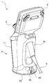
- FIG. 3 is a perspective view of the endoscope according to the present embodiment viewed from an obliquely rearward direction.
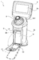
- FIG. 4 is a perspective view of the endoscope according to the present embodiment in a state where the battery replacement lid is opened halfway.
- FIG. 5 is a bottom view of the endoscope according to the present embodiment.
- the endoscope 1 is a battery-powered endoscope having a grip portion 2, a joystick 3, a display portion 4 capable of displaying an endoscopic image, and an insertion portion 5.
- the grip part 2 has a substantially cylindrical body part. As shown by a dotted line in FIG. 1, when the user who is an inspector grips the grip part 2 with one hand H (right hand or left hand), a part slightly below the center part of the grip part 2 so that the grip part 2 can be gripped firmly.
- the diameter of 2a has a shape that is slightly smaller than the diameter of the upper portion 2b slightly from the central portion of the grip portion 2.
- the lower part 2a and the upper part 2b constitute a body part.
- the housing 2x of the grip portion 2 has a portion extending to the upper portion 2b of the grip portion 2, and the display portion 4 is fixed to the extended portion. That is, the housing 2x is a housing of the grip unit 2 and the display unit 4.
- an arrow FS indicates the near side with respect to the display unit 4.
- the grip 2 has a bottom 2c that can be placed on a table such as a desk.
- the bottom portion 2c has an enlarged diameter and a flat bottom surface 2c1 so that the bottom portion 2c does not easily fall over when the grip portion 2 is placed on a table.
- the bottom surface 2c1 is a grounding surface for a table or the like. That is, the grip portion 2 of the endoscope 1 can stand on a stand or the like.
- the grip part 2 is self-supporting on a table or the like so that the longitudinal direction of the grip part 2 substantially coincides with the vertical direction.
- the bottom surface 2c1 is the bottom surface of the bottom plate member 2A as an anti-slip member fixed to the housing 2x of the grip portion 2 with a screw or the like.
- the housing 2x of the grip portion 2 is made of resin.
- the bottom plate member 2A is a member having a high friction coefficient, and is a rubber member here.
- the upper part 2d of the grip part 2 has an inclined surface 2d1, which is a plane inclined toward the front side.
- the joystick 3 as an operation device is provided so as to protrude in a direction orthogonal to the inclined surface 2d1. That is, the joystick 3 as an operating device is provided on the upper part 2 d side of the grip portion 2.
- the grip 2 is wider on the top 2d side than on the bottom 2c side when viewed from the front side.
- the grip portion 2 has a size that allows the user to grip with one hand and to operate the joystick 3 with the thumb in the gripped state. As shown by a dotted line in FIG. 1, the user can operate the joystick 3 with the thumb while holding the grip portion 2 with the hand H.
- the display unit 4 is disposed obliquely rearward from the upper part 2d of the gripping part 2 so that the display surface 4a faces slightly upward on the near side of the gripping part 2. That is, the display unit 4 is tilted to the back side of the grip unit 2.
- a flexible and elongated insertion portion 5 is provided on the back surface of the grip portion 2 so as to extend obliquely downward from the back surface. That is, the grip part 2 has a shape that can be gripped with one hand of the user, the display part 4 is fixed to the upper part 2d of the grip part 2, the base end of the insertion part 5 is connected, and the insertion part 5 extends from the back surface. I'm out.
- a holding hole 2e for holding the insertion portion 5 by locking the distal end portion of the insertion portion 5 is provided in the lower part on the back side of the bottom portion 2c of the grip portion 2.
- the holding hole 2e is a part of the bottom plate member 2A and is formed in an upward extension 2A1 that extends upward. The user can hold the distal end portion of the insertion portion 5 in the retaining hole 2e by passing the distal end portion of the insertion portion 5 through the retaining hole 2e.
- the holding hole 2e is formed in a member having a large frictional force, and holds the tip of the insertion portion 5 so that it does not slide down from the hole.
- the lid 11 is a lid that is provided on the front surface of the grip portion 2 and covers the battery housing portion 2B disposed inside the front surface side of the grip portion 2. That is, the battery housing portion 2 ⁇ / b> B capable of housing the battery 16 is provided in the grip portion 2 and is provided below the joystick 3.
- a hinge 13 for opening and closing the lid 11 is provided on the bottom 2c of the grip portion 2.
- the lid 11 is configured to be able to be opened by the hinge 13 so that the upper part of the lid 11 is tilted forward on the front side of the grip portion 2.
- the lid 11 is configured to be able to open from the upper side to the lower side in the longitudinal direction of the grip portion 2.
- the lid 11 is a lid for covering the battery housing portion 2B, and the lower portion of the lid 11 is pivotally supported by the hinge 13 at the lower portion of the grip portion 2, and is opened so that the upper portion of the lid 11 is tilted forward. It is possible.
- An unlocking operation member 14 for releasing the locked state in which the lid 11 is closed is provided on the top of the lid 11.
- the bottom surface of the bottom plate member 2 ⁇ / b> A is a bottom surface 2 c 1 of the bottom portion 2 c of the grip portion 2.
- the bottom surface 2c1 is a ground contact surface when the grip portion 2 of the endoscope 1 is placed on a desk, the ground, a table, or the like.
- the grip portion 2 has the bottom portion 2c having a flat ground surface, the grip portion to which the display portion 4 is fixed, and the insertion portion 5 to which the base end is connected is the back surface of the grip portion 2.
- the upper part of the holding part 2 is inclined forward to the front side opposite to the rear side.
- the gripping portion 2 of the endoscope 1 has a forward tilting posture so that it can stand on its own. That is, when the grip portion 2 is placed on the ground, a table or the like, the grip portion 2 is inclined forward.
- the axis C2 of the upper part 2b and the lower part 2a constituting the body part of the grip part 2 is inclined to the front side with respect to the axis O in the vertical direction.
- the axis C2 of the trunk portion is inclined toward the front side by an angle ⁇ 2 with respect to the vertical axis O orthogonal to the bottom surface 2c1.
- the angle ⁇ 2 is smaller than the angle ⁇ 1 described later.
- the angle ⁇ 2 is an angle in the range of 5 to 30 degrees, and is preferably about 10 degrees.
- the grip part 2 placed on a table or the like may be pulled to the back side due to the weight of the insertion part 5.
- the grip portion 2 has a forward tilting posture so that the upper portion 2d protrudes from the front side opposite to the pulled back side.
- the fact that the gripping part 2 is in the forward tilting posture causes a moment to the front side that is the opposite direction of the gripping part 2 with respect to the force that the gripping part 2 pulls downward on the back side due to the weight of the insertion part 5. It will be.
- the grip portion 2 has a forward tilted posture in which the upper portion 2d is tilted on the front side opposite to the back side, the grip portion 2 is gripped when placed on the ground, a table or the like. Part 2 is hard to fall.
- Insertion section 5 extending downward from the back side of the gripping section 2
- the insertion portion 5 is not in a direction perpendicular to the axis O of the gripping portion 2, but below the vertical axis O by a predetermined angle ⁇ ⁇ b> 1. It extends from the back of the opposite side.
- the predetermined angle ⁇ 1 is an angle in the range of 20 to 50 degrees, and preferably an angle in the range of 40 to 45 degrees.
- the axis C ⁇ b> 1 of the insertion portion 5 extending from the back surface of the grip portion 2 coincides with the axis of the joystick 3.
- the axis of the shaft part of the joystick 3 and the extending direction axis of the base end part of the insertion part 5 are coaxial. According to the above configuration, since the insertion portion 5 can be positioned below the grip portion 2 and the center of gravity of the grip portion 2 can be lowered, the grip portion 2 has good stability and is not easily tilted.
- the body part of the grip part 2 can stand independently with a forward leaning posture, and the insertion part 5 extends from the back side of the grip part 2, the area of the bottom surface of the grip part 2 is reduced and gripped.
- the whole part 2 can be reduced in size.
- Extension portion 2c2 extending to the back side of the bottom portion 2c of the grip portion 2
- the bottom portion 2 c of the grip portion 2 has an extension portion 2 c 2 extending on the back side of the grip portion 2 by an extension amount EX. Therefore, when the endoscope 1 is viewed from the side, the grip portion 2 has an L shape due to the body portion of the lower portion 2a and the upper portion 2b and the extending portion 2c2 of the bottom portion 2c. The grip portion 2 is pulled downward on the back side due to the weight of the insertion portion 5, but even if pulled downward on the back side, the grip portion 2 is unlikely to fall down by the extending portion 2c2 of the bottom portion 2c.
- extension 2c2 may further increase the extension amount EX as indicated by a dotted line.
- the bottom surface 2c1 which is a ground contact surface
- the bottom surface 2c1 which is a grounding surface
- the ground contact area R2 on the back side of the bottom surface 2c1 is formed wider than the ground contact area R1 on the front surface side of the bottom surface 2c1.
- the width L1 on the back side of the bottom surface 2c1 is formed wider than the width L2 on the front side. That is, the width on the back side of the bottom surface 2c1 of the bottom 2c is wider than the width on the front side. Therefore, when the grip portion 2 is pulled downward on the back side due to the weight of the insertion portion 5, the grip portion 2 is stable and difficult to fall down.
- Bottom plate member 2A which is a rubber member
- the bottom 2c is provided with a bottom plate member 2A as an anti-slip member, which is a rubber member having a large friction coefficient.
- the bottom plate member 2 ⁇ / b> A of the rubber member is heavier than the body portion made of a resin casing of the grip portion 2. That is, the bottom 2c is provided with a bottom plate member 2A made of a material heavier than the casing of the grip 2. Therefore, the position of the center of gravity of the grip portion 2 is lowered, and the grip portion 2 is not easily tilted.
- the bottom surface 2c1 has a large friction coefficient. Therefore, when the grip portion 2 is placed on a table or the like, the bottom surface of the bottom plate member 2A is difficult to slip, and the grip portion 2 stands on its own so as not to move firmly on the table or the like. Although the grip portion 2 is pulled to the back side due to the weight of the insertion portion 5, the bottom surface 2c1 is difficult to slip due to the friction of rubber, so that the grip portion 2 is less likely to drop from the top.
- the material of the bottom plate member 2A as an anti-slip member may be an elastomer or a foam material instead of rubber.
- a member having a magnet may be used.
- the battery 16 has a rectangular parallelepiped shape, and the battery 16 is accommodated in the battery accommodating portion 2B so that the longitudinal axis of the battery 16 is substantially parallel to the vertical axis. As shown by a dotted line in FIG. 2, the battery 16 accommodated in the battery accommodating portion 2 ⁇ / b> B is positioned closer to the front side on the bottom 2 c side of the grip portion 2.
- the fact that the battery 16 is on the front side of the gripping part 2 means that the moment of the gripping part 2 to the front side that is the opposite direction to the force that the gripping part 2 pulls downward on the back side due to the weight of the insertion part 5 is applied. Will be generated.
- the center of gravity of the grip portion 2 is lowered by being disposed on the bottom portion 2c side of the grip portion 2. Therefore, the stability of the gripping part 2 can be increased when placed on a table or the like.
- the battery 16 is placed in a so-called vertical orientation and accommodated in the battery accommodating portion 2B, the area of the bottom surface 2c1 can be reduced.
- Display unit 4 inclined to the back side of grip unit 2 As shown in FIG. 2, the display unit 4 is fixed so as to be inclined to the back side by a predetermined angle ⁇ ⁇ b> 3 with respect to the axis O of the grip unit 2. As a result, since the weight balance is achieved with respect to the forward tilting posture of the grip portion 2, the stability is good when opened on a table or the like. In addition, since the display part 4 inclines to the back side with respect to the axis
- the grip portion can be placed on a stand or the like independently, a large space can be narrowed for placing the endoscope.
- the endoscope can be used in various places because it does not easily fall over.
- the inspector performs an endoscopic inspection with the grip portion 2 placed on a table or the like, or temporarily places the grip portion 2 on the table or the like during the examination, or stores the endoscope 1. Sometimes the space for the place is small. Further, according to the above-described embodiment, the area of the bottom surface 2c1 of the grip portion 2 can be reduced, so that the endoscope can be reduced in size.
Landscapes
- Health & Medical Sciences (AREA)
- Life Sciences & Earth Sciences (AREA)
- Surgery (AREA)
- Physics & Mathematics (AREA)
- Engineering & Computer Science (AREA)
- Optics & Photonics (AREA)
- Medical Informatics (AREA)
- General Health & Medical Sciences (AREA)
- Pathology (AREA)
- Nuclear Medicine, Radiotherapy & Molecular Imaging (AREA)
- Biomedical Technology (AREA)
- Heart & Thoracic Surgery (AREA)
- Biophysics (AREA)
- Molecular Biology (AREA)
- Animal Behavior & Ethology (AREA)
- Radiology & Medical Imaging (AREA)
- Public Health (AREA)
- Veterinary Medicine (AREA)
- Multimedia (AREA)
- Astronomy & Astrophysics (AREA)
- General Physics & Mathematics (AREA)
- Mechanical Engineering (AREA)
- Instruments For Viewing The Inside Of Hollow Bodies (AREA)
- Endoscopes (AREA)
Abstract
置くためのスペースが比較的狭くて済み、かつ倒れ難い内視鏡を提供する。内視鏡1は、可撓性を有する挿入部5と、内視鏡画像を表示可能な表示部4と、接地面2c1を有する底部2cを有し、前記表示部が固定された把持部であって、前記挿入部の基端が接続されて前記挿入部が前記把持部の背面から下方へ延出し、前記背面とは反対側の前面側に上部2dが傾いた前傾姿勢を有する把持部2と、を有する。
Description
本発明は、把持部が自立可能な内視鏡に関する。
従来より、内視鏡が工業分野、医療分野などで広く利用されている。検査者は、細長い挿入部を検査対象内に挿入して、表示部に表示される内視鏡画像を見て、内視鏡検査を行う。検査者は、一方の手で操作部を操作し、他方の手で細長い挿入部を持ちながら挿入操作を行う。
内視鏡は、内視鏡検査中に台などの上に置いて使用される場合もある。また、内視鏡を使用しないときに、台などの上に一時的に置かれる場合もある。これらの場合、内視鏡には、簡単には倒れない安定性が要求される。特に、内視鏡は、細長い挿入部を有しているため、挿入部自体の重量により倒れ易いという問題がある。
そこで、特開2012-242537号公報には、持ち運び易さと安定性とが両立された筐体を備える内視鏡装置が提案されている。その提案の内視鏡装置では、挿入部は、グリップ部の軸に対して直交する方向に延出している。そして、装置の安定性を確保するために、内視鏡装置の筐体は、手前側から背面側に倒れるように形成されたグリップ部と、接地面を有するベース部とを有しており、側面視したときに略三角形に形成されている。
しかし、ベース部は手前側から背面側に沿って長い形状を有するため、内視鏡装置を置くには、比較的広いスペースが必要になるという問題がある。内視鏡装置を置くために広いスペースが必要になると、内視鏡装置の使用可能環境が限られてしまう。
そこで、本発明は、置くためのスペースが比較的狭くて済み、かつ倒れ難い内視鏡を提供することを目的とする。
本発明の一態様によれば、可撓性を有する挿入部と、内視鏡画像を表示可能な表示部と、接地面を有する底部を有し、前記表示部が固定された把持部であって、前記挿入部の基端が接続されて前記挿入部が前記把持部の背面から下方へ延出し、前記背面とは反対側の前面側に上部が傾いた前傾姿勢を有する把持部と、を有する内視鏡を提供することができる。
以下、図面を参照して本発明の実施の形態を説明する。
(全体構成)
図1は、本実施の形態に関わる内視鏡の正面図である。図2は、本実施の形態に関わる内視鏡の側面図である。図3は、本実施の形態に関わる内視鏡の斜め後ろ方向から視た斜視図である。図4は、本実施の形態に関わる、バッテリ交換用の蓋を途中まで開いた状態の内視鏡の斜視図である。図5は、本実施の形態に関わる内視鏡の底面図である。
図1は、本実施の形態に関わる内視鏡の正面図である。図2は、本実施の形態に関わる内視鏡の側面図である。図3は、本実施の形態に関わる内視鏡の斜め後ろ方向から視た斜視図である。図4は、本実施の形態に関わる、バッテリ交換用の蓋を途中まで開いた状態の内視鏡の斜視図である。図5は、本実施の形態に関わる内視鏡の底面図である。
内視鏡1は、把持部2と、ジョイスティック3と、内視鏡画像を表示可能な表示部4と、挿入部5とを有する、バッテリ駆動型の内視鏡である。
把持部2は、略円柱形状の胴体部を有する。図1に点線で示すように、検査者であるユーザが片手H(右手あるいは左手)で把持部2を把持したときに、しっかりと把持できる
ように、把持部2の中央部よりやや下側部分2aの径が、把持部2の中央部よりやや上側部分2bの径よりも、わずかに細くなるような形状を有している。下側部分2aと上側部分2bが、胴体部を構成する。
把持部2は、略円柱形状の胴体部を有する。図1に点線で示すように、検査者であるユーザが片手H(右手あるいは左手)で把持部2を把持したときに、しっかりと把持できる
ように、把持部2の中央部よりやや下側部分2aの径が、把持部2の中央部よりやや上側部分2bの径よりも、わずかに細くなるような形状を有している。下側部分2aと上側部分2bが、胴体部を構成する。
把持部2の筺体2xは、把持部2の上側部分2bに延出した部分を有し、その延出した部分には、表示部4が固定されて設けられている。すなわち、筺体2xは、把持部2と表示部4の筺体である。
なお、以下、ユーザが把持部2を片手で把持して表示部4に表示された検査画像である内視鏡画像を見ている状態のときに、表示部4の表示面4aに対向する側を、把持部2の手前側という。図2において、矢印FSが、表示部4に対する手前側を示す。
また、把持部2は、机などの台の上に載置可能な底部2cを有する。底部2cは、把持部2を台の上に載置したときに転倒し難いように、拡径しており、かつ平らな底面2c1を有する。底面2c1は、台などに対する接地面である。すなわち、内視鏡1の把持部2は、台などの上で自立可能となっている。把持部2は、把持部2の長手方向が垂直方向と略一致するように、台などの上で自立する。
なお、ここでは、底面2c1は、把持部2の筺体2xに螺子等により固定された、滑り防止部材としての底板部材2Aの底面である。把持部2の筺体2xは、樹脂製である。底板部材2Aは、摩擦係数の高い部材からなり、ここではゴム部材である。
把持部2の上部2dは、手前側に傾斜した平面である傾斜面2d1を有している。操作器であるジョイスティック3は、その傾斜面2d1に直交する方向に突出するように設けられている。すなわち、操作器としてのジョイスティック3は、把持部2の上部2d側に設けられている。そして、把持部2は、正面側からみたときに、底部2c側よりも上部2d側の方が幅が広い。
把持部2は、ユーザが片手で把持でき、かつ把持した状態で親指でジョイスティック3を操作できるサイズを有している。図1に点線で示すように、ユーザは、手Hで把持部2を把持しながら、親指でジョイスティック3を操作することができる。
表示部4は、表示面4aが把持部2の手前側のやや上方に向くように、把持部2の上部2dから斜め後方に傾いて配設されている。すなわち、表示部4は、把持部2の背面側に傾倒している。
図2及び図3に示すように、把持部2の背面には、可撓性を有し細長の挿入部5が、背面から斜め下方に向かって延出するように設けられている。すなわち、把持部2は、ユーザの片手で把持可能な形状を有し、表示部4が把持部2の上部2dに固定され、挿入部5の基端が接続されて挿入部5が背面から延出している。
また、把持部2の底部2cの背面側の下部には、挿入部5の先端部を係止して挿入部5を保持するための保持孔2eが設けられている。保持孔2eは、底板部材2Aの一部であって上方に延出した上方延出部2A1に形成されている。ユーザは、挿入部5の先端部を保持孔2eに通すことにより、挿入部5の先端部を保持孔2eに係止させて保持することができる。保持孔2eは、摩擦力の大きい部材に形成されており、挿入部5の先端部が孔から滑り落ちないように保持する。
蓋11は、把持部2の前面に設けられ、把持部2の前面側の内側に配設されたバッテリ収容部2Bを覆うための蓋である。すなわち、バッテリ16を収容可能なバッテリ収容部2Bは、把持部2に設けられており、かつ、ジョイスティック3の下方に設けられている。
そして、蓋11の開閉のためのヒンジ13が、把持部2の底部2cに設けられている。図4に示すように、蓋11は、ヒンジ13により、把持部2の前面側において、手前に上部を倒れるように開くことができるように構成されている。言い換えれば、蓋11は、把持部2の長手方向における上側から下側に向かって開くことができるように構成されている。
すなわち、蓋11は、バッテリ収容部2Bを覆うための蓋であって、蓋11の下部が把持部2の下部においてヒンジ13により軸支されながら、蓋11の上部を手前側に倒すように開けることが可能となっている。
蓋11の上部には、蓋11を閉じたロック状態を解除するためのロック解除操作部材14が設けられている。
また、図5に示すように、底板部材2Aの底面が、把持部2の底部2cの底面2c1となっている。底面2c1は、内視鏡1の把持部2を、机、地面、台などの上に置いたときの接地面である。
また、図5に示すように、底板部材2Aの底面が、把持部2の底部2cの底面2c1となっている。底面2c1は、内視鏡1の把持部2を、机、地面、台などの上に置いたときの接地面である。
以上のように、把持部2は、平らな接地面を有する底部2cを有し、表示部4が固定された把持部であって、基端が接続された挿入部5が把持部2の背面から下方へ延出し、その背面とは反対側の前面側に把持部2の上部が傾いた前傾姿勢を有している。
(把持部が安定的に自立するための構成)
次に、細長い挿入部5を有する内視鏡1の把持部2が、台などの上に置かれたときに、安定して自立できる構成について説明する。
次に、細長い挿入部5を有する内視鏡1の把持部2が、台などの上に置かれたときに、安定して自立できる構成について説明する。
1)把持部2の前傾姿勢
まず、内視鏡1の把持部2は、自立できるように、前傾姿勢を有している。すなわち、把持部2を地面、台の上等に載置したときに、把持部2は前方に傾斜している。把持部2の胴体部を構成する上側部分2bと下側部分2aの軸C2は、垂直方向の軸Oに対して前面側に傾いている。
まず、内視鏡1の把持部2は、自立できるように、前傾姿勢を有している。すなわち、把持部2を地面、台の上等に載置したときに、把持部2は前方に傾斜している。把持部2の胴体部を構成する上側部分2bと下側部分2aの軸C2は、垂直方向の軸Oに対して前面側に傾いている。
図2に示すように、側面視したときに、底面2c1に直交する垂直方向の軸Oに対して、胴体部の軸C2が手前側に、角度θ2だけ傾斜している。角度θ2は、後述する角度θ1よりも小さい。角度θ2は、5~30度の範囲の角度であり、この好ましくは、略10度である。
台などの上に置かれた把持部2は、挿入部5の重さにより、背面側に引っ張られる場合がある。その引っ張られる背面側とは反対側である前面側に上部2dが突出するように、把持部2は、前傾姿勢を有している。把持部2が前傾姿勢であることは、把持部2が挿入部5の重量により背面側の下方に引っ張る力に対して、把持部2をその逆方向である前面側へのモーメントを生じさせることになる。
以上のように、把持部2が、背面側とは反対側の前面側に上部2dが傾いた前傾姿勢を有しているので、地面、台の上等に載置された際に、把持部2は倒れ難い。
2)把持部2の背面側から下方に向けて延出する挿入部5
図2に示すように、挿入部5は、把持部2の軸Oに対して直交する方向ではなく、垂直方向の軸Oに対して所定の角度θ1だけ下方に、把持部2の前面とは反対側の背面から延出している。所定の角度θ1は、20~50度の範囲の角度であり、好ましくは、40~45度の範囲の角度である。
図2に示すように、把持部2の背面から延出する挿入部5の軸C1は、ジョイスティック3の軸と一致している。言い換えれば、ジョイスティック3の軸部の軸と、挿入部5の基端部の延出方向軸は同軸である。
以上のような構成によれば、挿入部5が把持部2の下方に位置させ、把持部2の重心を低くすることができるので、把持部2は、安定性が良く、倒れ難い。
図2に示すように、挿入部5は、把持部2の軸Oに対して直交する方向ではなく、垂直方向の軸Oに対して所定の角度θ1だけ下方に、把持部2の前面とは反対側の背面から延出している。所定の角度θ1は、20~50度の範囲の角度であり、好ましくは、40~45度の範囲の角度である。
図2に示すように、把持部2の背面から延出する挿入部5の軸C1は、ジョイスティック3の軸と一致している。言い換えれば、ジョイスティック3の軸部の軸と、挿入部5の基端部の延出方向軸は同軸である。
以上のような構成によれば、挿入部5が把持部2の下方に位置させ、把持部2の重心を低くすることができるので、把持部2は、安定性が良く、倒れ難い。
また、把持部2の胴体部が前傾姿勢を有して自立でき、かつ挿入部5が把持部2の背面側から延出しているので、把持部2の底面の面積を狭くして、把持部2全体を小型化することができる。
3)把持部2の底部2cの背面側に延出する延出部2c2
さらに、図2に示すように、把持部2の底部2cは、把持部2の背面側に、延出量EXだけ延出した延出部2c2を有している。よって、内視鏡1を側面視したときに、把持部2は、下側部分2aと上側部分2bの胴体部と底部2cの延出部2c2により、L字形状となっている。
把持部2は、挿入部5の重さにより背面側の下方に引っ張られるが、背面側の下方に引っ張られても、底部2cの延出部2c2によって倒れ難い。
さらに、図2に示すように、把持部2の底部2cは、把持部2の背面側に、延出量EXだけ延出した延出部2c2を有している。よって、内視鏡1を側面視したときに、把持部2は、下側部分2aと上側部分2bの胴体部と底部2cの延出部2c2により、L字形状となっている。
把持部2は、挿入部5の重さにより背面側の下方に引っ張られるが、背面側の下方に引っ張られても、底部2cの延出部2c2によって倒れ難い。
なお、延出部2c2は、点線で示すように、延出量EXをさらに大きくしてもよい。
4)底部2cの底面2c1の形状
図5に示すように、接地面である底面2c1は、前面側から背面側へ向かう前後方向の軸に対して、左右対称の形状を有している、そして、接地面である底面2c1は、前面側の接地面積R1と背面側の接地面積R2が異なる形状を有している。底面2c1の背面側の接地面積R2は、底面2c1の前面側の接地面積R1よりも広く形成されている。
その結果、挿入部5の重量により、把持部2が背面側の下方に引っ張られたときに、底面2c1の背面側の接地面積R2の接触領域で大きな摩擦を生じさせることができる。
図5に示すように、接地面である底面2c1は、前面側から背面側へ向かう前後方向の軸に対して、左右対称の形状を有している、そして、接地面である底面2c1は、前面側の接地面積R1と背面側の接地面積R2が異なる形状を有している。底面2c1の背面側の接地面積R2は、底面2c1の前面側の接地面積R1よりも広く形成されている。
その結果、挿入部5の重量により、把持部2が背面側の下方に引っ張られたときに、底面2c1の背面側の接地面積R2の接触領域で大きな摩擦を生じさせることができる。
さらに、図5に示すように、底面2c1の背面側の幅L1は、前面側の幅L2よりも広く形成されている。すなわち、底部2cの底面2c1の背面側の幅が前面側の幅より広い。よって、挿入部5の重量により、把持部2が背面側の下方に引っ張られたときに、把持部2は安定して、倒れ難くなっている。
よって、内視鏡1が台などの上に置かれたときに挿入部5の重量により角度θ1の下方に引っ張られ、さらに左右方向に少々引っ張られても、把持部2は倒れ難くなっている。5)ゴム部材である底板部材2A
底部2cには、摩擦係数の大きなゴム部材である、滑り防止部材としての底板部材2Aが設けられている。ゴム部材の底板部材2Aは、把持部2の樹脂製の筺体からなる胴体部よりも、重い。すなわち、底部2cには、把持部2の筺体よりも重い材質の底板部材2Aが設けられている。よって、把持部2の重心位置が低くなり、把持部2が倒れ難いようになっている。
底部2cには、摩擦係数の大きなゴム部材である、滑り防止部材としての底板部材2Aが設けられている。ゴム部材の底板部材2Aは、把持部2の樹脂製の筺体からなる胴体部よりも、重い。すなわち、底部2cには、把持部2の筺体よりも重い材質の底板部材2Aが設けられている。よって、把持部2の重心位置が低くなり、把持部2が倒れ難いようになっている。
また、ゴム部材であるため、底面2c1は摩擦係数が大きい。よって、把持部2を台などの上に置いたときに、底板部材2Aの底面が滑り難く、把持部2は、台などの上にしっかりと動かないようにして自立する。
把持部2が挿入部5の重量により背面側へ引っ張られるが、底面2c1がゴムの摩擦で滑りにくいので、把持部2は、台の上からの落下の可能性は低くなる。
把持部2が挿入部5の重量により背面側へ引っ張られるが、底面2c1がゴムの摩擦で滑りにくいので、把持部2は、台の上からの落下の可能性は低くなる。
なお、滑り防止部材としての底板部材2Aの材質は、ゴムの代わりに、エラストマー、発泡素材でもよい。さらに、内視鏡1の把持部2を置く場所が鉄板であれば、磁石を有する部材でもよい。
6)バッテリ16の位置
バッテリ16は直方体形状を有しており、バッテリ16は、バッテリ16の長手軸が垂直方向の軸と略平行になるように、バッテリ収容部2B内に収容される。そして、図2において点線で示すように、バッテリ収容部2B内に収容されたバッテリ16は、把持部2の底部2c側で前面側寄りに位置する。
バッテリ16は直方体形状を有しており、バッテリ16は、バッテリ16の長手軸が垂直方向の軸と略平行になるように、バッテリ収容部2B内に収容される。そして、図2において点線で示すように、バッテリ収容部2B内に収容されたバッテリ16は、把持部2の底部2c側で前面側寄りに位置する。
バッテリ16が把持部2の前面側にあることは、把持部2が挿入部5の重量により背面側の下方に引っ張る力に対して、把持部2をその逆方向である前面側へのモーメントを生じさせることになる。
バッテリ16は、比較的重いものであるので、把持部2の底部2c側に配置されることにより、把持部2の重心が低くなる。よって、台などの上に置いた時に、把持部2の安定性を高くすることができる。
また、バッテリ16を、いわゆる縦置きにしてバッテリ収容部2B内に収容するので、底面2c1の面積を小さくすることができる。
7)把持部2の背面側に傾斜した表示部4
図2に示すように、表示部4が把持部2の軸Oに対して所定の角度θ3だけ背面側に傾斜するように固定されている。その結果、把持部2の前傾姿勢に対して、重量バランスをとることになるので、台などの上に開いたときに、安定性がよい。
なお、表示部4が把持部2の軸Oに対して背面側に傾斜しているので、操作者にとって表示部4の画面が見やすい。
図2に示すように、表示部4が把持部2の軸Oに対して所定の角度θ3だけ背面側に傾斜するように固定されている。その結果、把持部2の前傾姿勢に対して、重量バランスをとることになるので、台などの上に開いたときに、安定性がよい。
なお、表示部4が把持部2の軸Oに対して背面側に傾斜しているので、操作者にとって表示部4の画面が見やすい。
以上のように、上述した実施の形態の内視鏡によれば、把持部を台などの上に自立して置くことが可能であるので、内視鏡を置くために広いスペースが狭くて済み、かつ倒れ難いので内視鏡を様々な場所で使用することができる。
検査者は、把持部2を台などの上に置いた状態で内視鏡検査を行ったり、検査中に把持部2を台などの上に一時的に置いたり、内視鏡1を保管するときには、置く場所のスペースが狭くて済む。
また、上述した実施の形態によれば、把持部2の底面2c1の面積を狭くできるので、内視鏡を小型化することができる。
また、上述した実施の形態によれば、把持部2の底面2c1の面積を狭くできるので、内視鏡を小型化することができる。
本発明によれば、置くためのスペースが比較的狭くて済み、かつ倒れ難い内視鏡を提供することができる。
本発明は、上述した実施の形態に限定されるものではなく、本発明の要旨を変えない範囲において、種々の変更、改変等が可能である。
本出願は、2014年7月2日に日本国に出願された特願2014-137056号を優先権主張の基礎として出願するものであり、上記の開示内容は、本願明細書、請求の範囲に引用されるものとする。
Claims (10)
- 可撓性を有する挿入部と、
内視鏡画像を表示可能な表示部と、
接地面を有する底部を有し、前記表示部が固定された把持部であって、前記挿入部の基端が接続されて前記挿入部が前記把持部の背面から下方へ延出し、前記背面とは反対側の前面側に上部が傾いた前傾姿勢を有する把持部と、
を有することを特徴とする内視鏡。 - 前記底部は、前記背面側に延出した延出部を有することを特徴とする請求項1に記載の内視鏡。
- 前記接地面の前記背面側の面積は、前記接地面の前記前面側の面積よりも広いことを特徴とする請求項2に記載の内視鏡。
- 前記接地面の前記背面側の幅は、前記接地面の前記前面側の幅よりも広いことを特徴とする請求項2に記載の内視鏡。
- 前記把持部の前記底部に設けられた滑り防止部材を有し、
前記滑り防止部材が前記接地面を有することを特徴とする請求項3に記載の内視鏡。 - 前記滑り防止部材は、ゴム部材であることを特徴とする請求項5に記載の内視鏡。
- 前記把持部の上部側に設けられた操作器としてのジョイスティックを有し、
前記ジョイスティックの軸部の軸と、前記挿入部の前記基端の延出方向の軸は、同軸上にあることを特徴とする請求項1に記載の内視鏡。 - 前記表示部は、前記把持部の上部において固定されており、
前記表示部は、前記背面側に傾倒していることを特徴とする請求項1に記載の内視鏡。 - 前記把持部に設けられ、バッテリを収容可能なバッテリ収容部を有し、
前記バッテリは、前記バッテリ収容部に収容されると、前記把持部の前面側寄りに位置することを特徴とする請求項1に記載の内視鏡。 - 前記把持部の前記底部の前記背面側に、前記挿入部を保持するための保持孔を有することを特徴とする請求項2に記載の内視鏡。
Priority Applications (1)
| Application Number | Priority Date | Filing Date | Title |
|---|---|---|---|
| US15/394,938 US20170105603A1 (en) | 2014-07-02 | 2016-12-30 | Endoscope |
Applications Claiming Priority (2)
| Application Number | Priority Date | Filing Date | Title |
|---|---|---|---|
| JP2014-137056 | 2014-07-02 | ||
| JP2014137056A JP6315800B2 (ja) | 2014-07-02 | 2014-07-02 | 内視鏡 |
Related Child Applications (1)
| Application Number | Title | Priority Date | Filing Date |
|---|---|---|---|
| US15/394,938 Continuation US20170105603A1 (en) | 2014-07-02 | 2016-12-30 | Endoscope |
Publications (1)
| Publication Number | Publication Date |
|---|---|
| WO2016002243A1 true WO2016002243A1 (ja) | 2016-01-07 |
Family
ID=54089056
Family Applications (1)
| Application Number | Title | Priority Date | Filing Date |
|---|---|---|---|
| PCT/JP2015/052702 Ceased WO2016002243A1 (ja) | 2014-07-02 | 2015-01-30 | 内視鏡 |
Country Status (4)
| Country | Link |
|---|---|
| US (1) | US20170105603A1 (ja) |
| JP (1) | JP6315800B2 (ja) |
| CN (2) | CN105266749B (ja) |
| WO (1) | WO2016002243A1 (ja) |
Families Citing this family (4)
| Publication number | Priority date | Publication date | Assignee | Title |
|---|---|---|---|---|
| JP6315800B2 (ja) * | 2014-07-02 | 2018-04-25 | オリンパス株式会社 | 内視鏡 |
| USD852357S1 (en) * | 2015-09-18 | 2019-06-25 | Olympus Corporation | Endoscope operating unit |
| JP7329428B2 (ja) * | 2019-12-04 | 2023-08-18 | Hoya株式会社 | 内視鏡装置 |
| US12268359B2 (en) * | 2023-03-13 | 2025-04-08 | Endoluxe Inc. | Handheld unit for endoscopy, laparoscopy, and other scopic procedures and methods of manufacture and use thereof |
Citations (4)
| Publication number | Priority date | Publication date | Assignee | Title |
|---|---|---|---|---|
| WO2002056756A2 (en) * | 2001-01-19 | 2002-07-25 | Framtidartaekni Ehf. | Hand-held digital imaging diagnostic and operational instrument with wireless transmission data of image |
| JP2011069883A (ja) * | 2009-09-24 | 2011-04-07 | Olympus Corp | 内視鏡装置 |
| JP2011067256A (ja) * | 2009-09-24 | 2011-04-07 | Olympus Corp | 内視鏡装置 |
| JP2011239989A (ja) * | 2010-05-19 | 2011-12-01 | Olympus Medical Systems Corp | 内視鏡 |
Family Cites Families (6)
| Publication number | Priority date | Publication date | Assignee | Title |
|---|---|---|---|---|
| JP5144902B2 (ja) * | 2006-06-08 | 2013-02-13 | Hoya株式会社 | 電子内視鏡の操作部 |
| GB2493606B (en) * | 2008-03-07 | 2013-03-27 | Milwaukee Electric Tool Corp | Visual inspection device |
| CN102665525B (zh) * | 2010-12-24 | 2013-09-25 | 奥林巴斯株式会社 | 内窥镜装置 |
| EP2484270B1 (en) * | 2010-12-24 | 2014-03-12 | Olympus Corporation | Endoscopic device |
| JP5749564B2 (ja) * | 2011-05-18 | 2015-07-15 | オリンパス株式会社 | 内視鏡装置 |
| JP6315800B2 (ja) * | 2014-07-02 | 2018-04-25 | オリンパス株式会社 | 内視鏡 |
-
2014
- 2014-07-02 JP JP2014137056A patent/JP6315800B2/ja not_active Expired - Fee Related
-
2015
- 2015-01-30 WO PCT/JP2015/052702 patent/WO2016002243A1/ja not_active Ceased
- 2015-04-24 CN CN201510202274.3A patent/CN105266749B/zh not_active Expired - Fee Related
- 2015-04-24 CN CN201520257635.XU patent/CN204636268U/zh not_active Withdrawn - After Issue
-
2016
- 2016-12-30 US US15/394,938 patent/US20170105603A1/en not_active Abandoned
Patent Citations (4)
| Publication number | Priority date | Publication date | Assignee | Title |
|---|---|---|---|---|
| WO2002056756A2 (en) * | 2001-01-19 | 2002-07-25 | Framtidartaekni Ehf. | Hand-held digital imaging diagnostic and operational instrument with wireless transmission data of image |
| JP2011069883A (ja) * | 2009-09-24 | 2011-04-07 | Olympus Corp | 内視鏡装置 |
| JP2011067256A (ja) * | 2009-09-24 | 2011-04-07 | Olympus Corp | 内視鏡装置 |
| JP2011239989A (ja) * | 2010-05-19 | 2011-12-01 | Olympus Medical Systems Corp | 内視鏡 |
Also Published As
| Publication number | Publication date |
|---|---|
| JP2016013314A (ja) | 2016-01-28 |
| JP6315800B2 (ja) | 2018-04-25 |
| CN105266749B (zh) | 2018-03-20 |
| CN204636268U (zh) | 2015-09-16 |
| US20170105603A1 (en) | 2017-04-20 |
| CN105266749A (zh) | 2016-01-27 |
Similar Documents
| Publication | Publication Date | Title |
|---|---|---|
| CN102665523B (zh) | 内窥镜装置 | |
| CN102665525B (zh) | 内窥镜装置 | |
| CN102711581B (zh) | 内窥镜装置 | |
| CN102665524B (zh) | 内窥镜装置 | |
| JP6315800B2 (ja) | 内視鏡 | |
| US10918267B2 (en) | Endoscope | |
| CN100415153C (zh) | 内窥镜装置 | |
| JP5719890B2 (ja) | 放射線測定装置 | |
| JP6266173B2 (ja) | 携帯型内視鏡 | |
| JP5129774B2 (ja) | 超音波診断装置 | |
| WO2016002242A1 (ja) | 内視鏡 | |
| JP5340865B2 (ja) | 内視鏡装置 | |
| JP6625400B2 (ja) | 内視鏡装置 |
Legal Events
| Date | Code | Title | Description |
|---|---|---|---|
| 121 | Ep: the epo has been informed by wipo that ep was designated in this application |
Ref document number: 15814814 Country of ref document: EP Kind code of ref document: A1 |
|
| NENP | Non-entry into the national phase |
Ref country code: DE |
|
| 122 | Ep: pct application non-entry in european phase |
Ref document number: 15814814 Country of ref document: EP Kind code of ref document: A1 |