WO2016001985A1 - Measurement method, measurement device, measurement program, and computer-readable recording medium recording measurement program - Google Patents
Measurement method, measurement device, measurement program, and computer-readable recording medium recording measurement program Download PDFInfo
- Publication number
- WO2016001985A1 WO2016001985A1 PCT/JP2014/067419 JP2014067419W WO2016001985A1 WO 2016001985 A1 WO2016001985 A1 WO 2016001985A1 JP 2014067419 W JP2014067419 W JP 2014067419W WO 2016001985 A1 WO2016001985 A1 WO 2016001985A1
- Authority
- WO
- WIPO (PCT)
- Prior art keywords
- phase
- plane
- measurement
- image
- grid
- Prior art date
Links
Images


Classifications
-
- G—PHYSICS
- G01—MEASURING; TESTING
- G01B—MEASURING LENGTH, THICKNESS OR SIMILAR LINEAR DIMENSIONS; MEASURING ANGLES; MEASURING AREAS; MEASURING IRREGULARITIES OF SURFACES OR CONTOURS
- G01B11/00—Measuring arrangements characterised by the use of optical techniques
- G01B11/24—Measuring arrangements characterised by the use of optical techniques for measuring contours or curvatures
- G01B11/25—Measuring arrangements characterised by the use of optical techniques for measuring contours or curvatures by projecting a pattern, e.g. one or more lines, moiré fringes on the object
- G01B11/2513—Measuring arrangements characterised by the use of optical techniques for measuring contours or curvatures by projecting a pattern, e.g. one or more lines, moiré fringes on the object with several lines being projected in more than one direction, e.g. grids, patterns
-
- G—PHYSICS
- G01—MEASURING; TESTING
- G01B—MEASURING LENGTH, THICKNESS OR SIMILAR LINEAR DIMENSIONS; MEASURING ANGLES; MEASURING AREAS; MEASURING IRREGULARITIES OF SURFACES OR CONTOURS
- G01B11/00—Measuring arrangements characterised by the use of optical techniques
- G01B11/24—Measuring arrangements characterised by the use of optical techniques for measuring contours or curvatures
- G01B11/25—Measuring arrangements characterised by the use of optical techniques for measuring contours or curvatures by projecting a pattern, e.g. one or more lines, moiré fringes on the object
- G01B11/254—Projection of a pattern, viewing through a pattern, e.g. moiré
-
- G—PHYSICS
- G06—COMPUTING; CALCULATING OR COUNTING
- G06T—IMAGE DATA PROCESSING OR GENERATION, IN GENERAL
- G06T7/00—Image analysis
- G06T7/50—Depth or shape recovery
- G06T7/521—Depth or shape recovery from laser ranging, e.g. using interferometry; from the projection of structured light
Definitions
- the present invention is a non-contact, high-speed, high-speed measurement of the three-dimensional shape of the surface of a measurement object having a three-dimensional surface shape, such as a large structure, an industrial product, a sheet-like structure, a human body, animals and plants, or a natural shaped object.
- the present invention relates to a three-dimensional shape measuring apparatus that can be performed with high accuracy. It can also be used for non-contact vibration surface position measurement and displacement distribution measurement.
- a grid projection method for measuring a three-dimensional shape by projecting a grid pattern onto a measurement object and obtaining a phase for each pixel of a grid pattern image obtained by imaging the grid pattern projected onto the measurement object is known. is there.
- Fig. 6 shows an example of an optical system of a shape measuring apparatus using a one-dimensional grid projection method.
- the center of the camera lens and the height of the light source of the projector are the same as the reference plane, and the camera imaging plane and the grating plane are moiré topography optical systems parallel to the reference plane.
- moire topography a white line can be photographed as a contour line at the position W in FIG. 6 and a black line can be photographed as a contour line at the position B.
- the lattice projection method can analyze the deformation with high accuracy by analyzing the phase of the lattice, and can measure out-of-plane deformation and three-dimensional shape with high accuracy.
- a phase analysis method a phase shift method or a Fourier transform method is used.
- Non-Patent Document 1 the deformation of the object can be analyzed with high accuracy by analyzing the phase of the lattice, and in-plane deformation and high-precision measurement of a three-dimensional shape are possible (Non-Patent Document 1). , 2).
- a phase analysis method a phase shift method or a Fourier transform method is used.
- the sampling moire method Non-Patent Document 3
- the Fourier transform method Non-Patent Documents 4 and 5 are useful for analyzing moving objects and the like because the phase can be analyzed with one image.
- the sampling moire method uses two periods of data to calculate the phase
- the Fourier transform method uses all pixel data to analyze the phase, and it can measure moving images with a small amount of image data. I could not.
- the present invention is a new grating projection method for analyzing the phase of image data for one grating period by Fourier transform or the like. As a result, the phase distribution can be analyzed from one image at a high speed, and a moving image can also be analyzed.
- the features of the present invention are as follows. (1) Since the measurement is based on phase analysis, the accuracy is good. (2) Since phase analysis can be performed with a single image, the shape of a moving object can be measured. (3) Since only frequency 1 is extracted by Fourier transform, it is not necessary to project a grid having an accurate cosine wave luminance distribution. (4) Since only frequency 1 is extracted by Fourier transform, noise that appears in the high-frequency portion is automatically deleted, so that it is resistant to noise. (5) Processing is simple and processing can be performed at high speed. (6) The gauge length is N pixels, which is shorter than the sampling moire method. Generally, the gauge length is shorter than the digital image correlation method. (7) In the sampling moire method, moire fringes are generated by linear interpolation. However, since the present invention correlates with a cosine wave, the accuracy is higher.
- FIG. 1 is an explanatory diagram of an optical system of moire topography.
- FIG. 2A is an explanatory diagram of the relationship between the phase of the object viewed by one pixel on the camera imaging surface and the phase of the reference surface.
- FIG. 2B is an explanatory diagram of the relationship between the phase of the object viewed by one pixel on the camera imaging surface and the phase of the reference surface.
- FIG. 3 shows the overall configuration of the apparatus according to the first embodiment.
- FIG. 4 is an image of a grid reflected on the camera imaging surface.
- FIG. 5A shows a grid processing procedure.
- FIG. 5C is a grid processing procedure.
- FIG. 5C is a grid processing procedure.
- FIG. 6 shows a grating projection optical system (moire topography).
- the present invention is a method of photographing an object surface grid with a camera, analyzing it, and measuring it.
- it is also possible to measure the displacement of the object surface in the lateral direction by photographing a lattice pattern provided on the object surface with a camera.
- ⁇ Optical system and coordinates> 1 and 2 are schematic diagrams for explaining the lattice projection mechanism of the shape measuring apparatus and the measurement object.
- L represents the position of the light source
- V represents the center of the camera lens.
- the grating is at a distance of d from the position L of the light source, and the width of one period is p.
- the center V of the camera lens and the height of the light source L of the projector are the same with respect to the reference plane, and the camera imaging plane and the lattice plane are parallel to the reference plane.
- the object plane is located at a distance z1 away from the light source L
- the reference plane is located at a distance z2 away
- the lattice plane is located at a position d away from the light source L.
- the lattice plane is parallel to the reference plane, and equally spaced one-dimensional lattice lines having a period p are drawn.
- a point light source is used as the light source, but a one-line light source parallel to the grid lines may be used.
- a surface including the light source L and parallel to the reference surface is called a light source surface.
- x, y, z coordinates are taken with the light source as the origin, and the direction perpendicular to the reference plane is taken as the z direction.
- the lower side is positive in the z direction.
- the direction perpendicular to the grid lines drawn on the plane of the grid is the x direction
- the direction parallel to the grid lines is the y direction.
- the center of the camera lens is in the light source plane and is separated from the light source L by a distance v in the x direction.
- the camera imaging plane is parallel to the reference plane and the lattice plane, and the i direction and j direction of the pixel coordinates (i, j) of the camera imaging plane coincide with the x direction and the y direction, respectively.
- the image of one period of the grating on the camera imaging surface has the same width regardless of the height of the object plane or the reference plane. Therefore, if it is set so that one period of the grating is reflected in N pixels on the imaging surface of the digital camera, an image of one period of the grating is reflected in N pixels regardless of the height of the object plane or the reference plane. This will be described with reference to FIG.
- the projected shadow of one period of the grating is x1 on the object plane and x2 on the reference plane.
- the distance from the light source plane is z1 on the object plane, z2 on the reference plane, z3 on the camera imaging plane, and d on the lattice plane.
- the shadow of one period p of the grating is x1 obtained by multiplying p by z1 / d on the object plane, and x2 obtained by multiplying p by z2 / d on the reference plane.
- the size x4 on the camera imaging surface is x1 multiplied by z3 / z1
- x5 is the size obtained by multiplying x2 by z3 / z2
- x4 and x5 are both z3 / d times p. That is, the size of one period of the grating reflected on the camera imaging surface is determined by the ratio of the distance from the light source surface to the grating and the distance from the center of the camera lens to the camera imaging surface. Not affected.
- the number of grids reflected on the camera imaging surface and the number of pixels on the camera imaging surface are always proportional, and the number of sensor pixels of the camera that captures an image of one grating period is constant regardless of the height of the object to be measured. Become. That is, if one period of the grating is set to be reflected in N pixels, one period of the grating is always reflected in consecutive N pixels.
- the position at which the grating is reflected on the camera imaging surface changes when the distance to the object plane or the reference plane changes.
- the phase of the grating reflected on the pixels on the camera imaging surface changes depending on the height from the reference plane to the object plane.
- the height can be obtained by phase analysis. That is, if the N pixel is subjected to Fourier transform, the frequency 1 having the maximum power spectrum is extracted, and the phase of the frequency 1 is obtained, the height of the object surface or the like can be measured. In actual measurement, the height of the object surface or the like can be measured by setting the frequency in advance according to the optical system and obtaining the phase of the preset frequency.
- FIG. 2A is an enlarged view of the upper part of FIG. 2B.
- the center V of the camera lens is placed at the position of coordinates (v, 0, 0) on the x axis. That is, the center V of the camera lens is separated from the light source L by a distance v.
- the point S on the object plane is reflected.
- a line passing through the pixel, the point S, and the point R is shown as a camera line of sight.
- a point obtained by projecting the point S on the object plane perpendicular to the z-axis is designated as point B
- a point obtained by projecting the point R on the reference plane perpendicular to the z-axis is designated as point I.
- a point where light from the light source position L to the point R passes through the lattice plane is defined as a point Q, and a light line from the light source position L to the point R projected from the point S on the object plane perpendicular to the z-axis is a line.
- a point where the light crosses is defined as a point P.
- a point where light from the position L of the light source to the point S passes through the lattice plane is defined as a point G.
- Point E is the origin of the grid, and the distance between point C and point E is e.
- the distance between the points I and B, that is, the height from the reference plane to the object plane is set as h.
- a g amplitude, [Phi lattice phase, b g is the background.
- the light source illuminates the grid, and the shadow of the grid is projected onto the reference plane or the object plane.
- the luminance distribution when the shadow of the grid is reflected on the camera imaging surface is expressed by the following expression with respect to continuous N pixels corresponding to one period of the grid at the height z of the reference plane and the object plane.
- n 0, 1,... N.
- the discrete Fourier transform is performed on the N pieces of data, the frequency 1 is extracted, and the phase is obtained therefrom, the phase ⁇ of the smooth cosine wave can be obtained. Good phase analysis can be performed.
- phase ⁇ ( ⁇ ⁇ ⁇ ⁇ ) can be calculated using the following formula.
- phase ⁇ of the grating can be obtained.
- phase ⁇ R of the shadow of the grid projected on the point R on the reference plane is
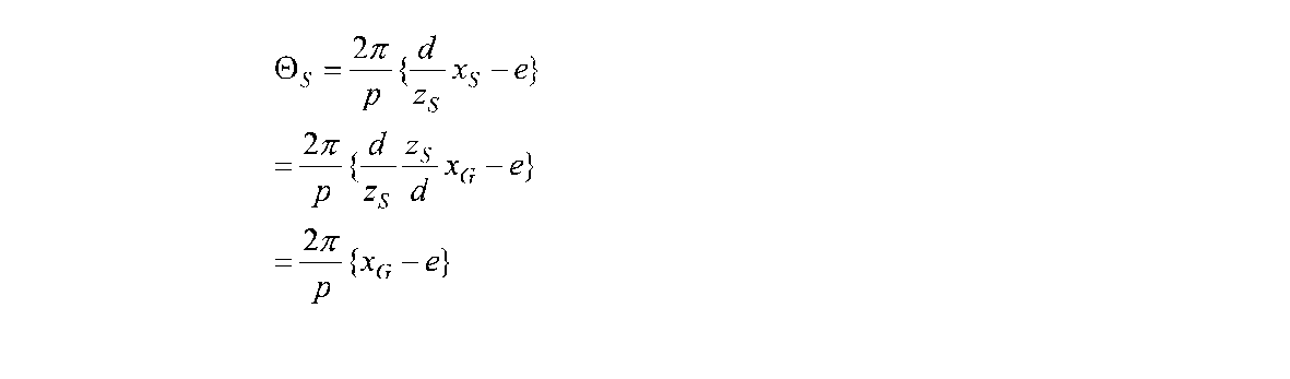
- phase ⁇ S of the shadow of the lattice projected onto the point S on the object is as follows.
- the phase ⁇ M of the moire fringe is obtained as in the following equation.
- the height h from the reference plane to the object plane is obtained by measuring the phase of the moire fringes as the phase difference between the reference plane grating and the object plane grating.
- Fig. 3 shows the overall configuration of the measuring apparatus of Example 1.
- 1 is a lamp such as an LED, which corresponds to a light source.
- 2 is a grid
- 3 is an object to be measured
- 4 is a mounting table
- 5 is a digital camera
- 6 is an image sensor
- 7 is a lens
- 8 is a computer
- 9 is an output device. If only the measurement result is obtained, the result may be stored in the computer 8 or the like, so that the output device 9 is not necessary.
- a projector such as a commercially available liquid crystal projector may be used as the lamp 1 and the grid 2 .
- the lattice 2 is formed by displaying the lattice with a liquid crystal display element or the like. When a projector is used, the width and direction of the lattice can be freely changed.
- the object 3 When the object 3 is irradiated with the lamp 1, the shadow of the lattice 2 is projected on the object surface, and a shadow image is reflected on the image sensor 6 of the digital camera 5 through the lens 7.
- the reflected image is sent from the digital camera 5 to the computer 8.
- the image In the computer 8, the image is analyzed by a stored program for realizing the method of the present invention, and a measured value is obtained.
- the obtained measurement values are stored in the computer 8 and, if necessary, processed into an output image or the like, sent to the output device 9 and output.
- the output device is a display device or a printing device.
- the reference surface may be the surface of the mounting table 4, and an object having the reference surface may be mounted on the mounting table 4. Since measurement is possible if there is a reference plane and an object plane, an object having an object plane may be placed instead of the reference plane. It is also possible to measure the object surface shape in the horizontal direction with the lamp 1, the grid 2, the object 3, the mounting table 4, and the digital camera 5 in the horizontal state, and to measure in the oblique direction. Is also possible.
- FIG. 4 is an enlarged explanatory view of a part of the image photographed in this way.
- the hatched portion indicates a portion where the luminance of the lattice is low, and the other portion indicates a portion where the luminance of the lattice is high.
- the direction perpendicular to the grid line is defined as the x direction, and the direction perpendicular thereto is defined as the y direction.
- the coordinates of the pixel on the camera imaging surface be (i, j). Then, the i direction and the j direction are photographed in accordance with the x direction and the y direction, respectively.
- This image is processed as follows.
- (1) One-dimensional Fourier transform is performed on image data (FIG. 5A) of consecutive N pixels.
- phase connection can be easily made by increasing or decreasing 2 ⁇ every time a phase jump occurs.
- the moiré fringe phase ⁇ M which is the phase difference between the phase of the object and the phase of the reference plane grating, is obtained for each pixel. From this, the height h can be obtained using Equation 17.
- phase of frequency 1 or the like is obtained after Fourier transform, it is possible to perform measurement resistant to noise without projecting a grating having an accurate luminance distribution of cosine waves.
- Example 1 the height and shape of the object plane were measured, but the object plane originally had a grid on the object plane without using a projection grid, a film on which the grid was drawn, or the like. For example, by using a grid, it is possible to measure the displacement of the object plane in the horizontal direction by photographing the grid of the object plane.
- an image is obtained by photographing the lattice of the object plane with a camera before and after displacement.
- the image is Fourier-transformed, and the phase of frequency 1 is phase-connected to store the phase corresponding to each pixel.
- the distance displaced in the horizontal direction is obtained by the product of the phase difference before and after the displacement and the grating period.
Abstract
Description
(1)位相解析による計測であるため精度が良い。
(2)1枚の画像で位相解析できるので、運動する物体の形状計測が可能である。
(3)フーリエ変換により周波数1のみを抽出しているので、正確な余弦波の輝度分布をもつ格子を投影しなくても良い。
(4)また、フーリエ変換により周波数1のみを抽出しているので、高周波部分に現れるノイズは自動的に削除されるためノイズに強い。
(5)処理が簡単で、高速に処理ができる。
(6)ゲージ長がN画素となり、サンプリングモアレ法よりも短い。一般的に、デジタル画像相関法よりもゲージ長が短い。
(7)サンプリングモアレ法では直線補間によりモアレ縞を生成しているが、本発明は余弦波と相関をとっていることになるため、精度がより高い。 The features of the present invention are as follows.
(1) Since the measurement is based on phase analysis, the accuracy is good.
(2) Since phase analysis can be performed with a single image, the shape of a moving object can be measured.
(3) Since only
(4) Since only
(5) Processing is simple and processing can be performed at high speed.
(6) The gauge length is N pixels, which is shorter than the sampling moire method. Generally, the gauge length is shorter than the digital image correlation method.
(7) In the sampling moire method, moire fringes are generated by linear interpolation. However, since the present invention correlates with a cosine wave, the accuracy is higher.
<光学系と座標>
図1,2に形状計測装置の格子投影機構と計測対象物の説明用概略図を示す。 First, the measurement principle will be described.
<Optical system and coordinates>
1 and 2 are schematic diagrams for explaining the lattice projection mechanism of the shape measuring apparatus and the measurement object.
格子の1周期pの影は、物体面ではpをz1/d倍したx1となり、基準面ではpをz2/d倍したx2となる。カメラ撮像面での大きさx4はx1をz3/z1倍したものであり、x5はx2をz3/z2倍した大きさであるから、x4とx5はともにpのz3/d倍になる。すなわち、カメラ撮像面に映る格子の1周期の大きさは光源面から格子までの距離と、カメラレンズの中心からカメラ撮像面までの距離の比によって定まり、物体面や基準面までの距離には影響されない。 The projected shadow of one period of the grating is x1 on the object plane and x2 on the reference plane. The distance from the light source plane is z1 on the object plane, z2 on the reference plane, z3 on the camera imaging plane, and d on the lattice plane.
The shadow of one period p of the grating is x1 obtained by multiplying p by z1 / d on the object plane, and x2 obtained by multiplying p by z2 / d on the reference plane. Since the size x4 on the camera imaging surface is x1 multiplied by z3 / z1, and x5 is the size obtained by multiplying x2 by z3 / z2, x4 and x5 are both z3 / d times p. That is, the size of one period of the grating reflected on the camera imaging surface is determined by the ratio of the distance from the light source surface to the grating and the distance from the center of the camera lens to the camera imaging surface. Not affected.
<投影格子の位相>
いま、z=dにある格子の透過率分布Igは余弦波状になっており、次の式で示される。 First, the center V of the camera lens is placed at the position of coordinates (v, 0, 0) on the x axis. That is, the center V of the camera lens is separated from the light source L by a distance v. When the object is placed on the pixel on the camera imaging surface where the point R on the reference plane is reflected, the point S on the object plane is reflected. In FIG. 2, a line passing through the pixel, the point S, and the point R is shown as a camera line of sight. A point obtained by projecting the point S on the object plane perpendicular to the z-axis is designated as point B, and a point obtained by projecting the point R on the reference plane perpendicular to the z-axis is designated as point I. A point where light from the light source position L to the point R passes through the lattice plane is defined as a point Q, and a light line from the light source position L to the point R projected from the point S on the object plane perpendicular to the z-axis is a line. A point where the light crosses is defined as a point P. Further, a point where light from the position L of the light source to the point S passes through the lattice plane is defined as a point G. Let the intersection of the z-axis and the lattice plane be point C. Point E is the origin of the grid, and the distance between point C and point E is e. The distance between the points I and B, that is, the height from the reference plane to the object plane is set as h.
<Phase of projection grating>
Now, the transmittance distribution I g of the grating in the z = d has become a cosine wave, shown by the following equation.


モアレトポグラフィにおいては、等高線を表すモアレ縞の位相ΘMは、基準面に投影された格子の位相ΘRと物体の上に投影された格子の位相Θの差ΘM=Θ-ΘRとして求められる。これよりzが求められ、あるいは基準面からの高さh=zR-zが求められる。 <Phase of moire fringes representing contour lines>
In moire topography, the phase Θ M of the moire fringe representing the contour line is obtained as a difference Θ M = Θ−Θ R between the phase Θ R of the grating projected onto the reference plane and the phase Θ R of the grating projected onto the object. It is done. From this, z is obtained or the height from the reference plane h = z R −z is obtained.


基準面に一次元格子を投影する。これをデジタルカメラで撮影する。図4はこのようにして撮影した画像の一部の拡大説明図である。この例の場合、格子の1周期をカメラ撮像面のN画素(ここではN=8)となるように倍率を調節している。カメラ撮像面の画素が黒い長方形で表現されている。この図の斜線で示される部分は格子の輝度の低い部分を示し、その他の部分は格子の輝度の高い部分を示している。格子線に直角な方向をx方向、それに垂直な方向をy方向とする。カメラ撮像面における画素の座標を(i,j)とする。そして、i方向、j方向をそれぞれx方向およびy方向に合わせて撮影する。 <Phase analysis procedure>
Project a one-dimensional grid onto the reference plane. Take this with a digital camera. FIG. 4 is an enlarged explanatory view of a part of the image photographed in this way. In this example, the magnification is adjusted so that one period of the grating becomes N pixels (here, N = 8) on the camera imaging surface. Pixels on the camera imaging surface are represented by black rectangles. In this figure, the hatched portion indicates a portion where the luminance of the lattice is low, and the other portion indicates a portion where the luminance of the lattice is high. The direction perpendicular to the grid line is defined as the x direction, and the direction perpendicular thereto is defined as the y direction. Let the coordinates of the pixel on the camera imaging surface be (i, j). Then, the i direction and the j direction are photographed in accordance with the x direction and the y direction, respectively.
(1)連続するN画素の画像データ(図5A)を一次元フーリエ変換する。
(2)これにより-N/2~N/2の周波数スペクトル(図5B)が得られる。この中で最大のパワースペクトルをもつ、N画素を一周期とする周波数1または周波数-1の成分を抽出する。図5Bでは、周波数1だけを取り出している。
(3)その抽出した周波数の位相計算を行えば位相が得られる。そして、そのN画素の格子の先頭の画素に対応して記憶する。(図5C)
(4)次に、N画素の格子の組み合わせをx方向に1画素だけずらして(1)~(3)の位相計算と記憶を繰り返す。
(5)x方向の移動がすべて終わったら(1)~(4)の走査をすべてのy方向について行う。 This image is processed as follows.
(1) One-dimensional Fourier transform is performed on image data (FIG. 5A) of consecutive N pixels.
(2) As a result, a frequency spectrum of -N / 2 to N / 2 (FIG. 5B) is obtained. Among them, a component of
(3) The phase can be obtained by calculating the phase of the extracted frequency. And it memorize | stores corresponding to the head pixel of the grid of the N pixel. (Fig. 5C)
(4) Next, the phase calculation and storage in (1) to (3) are repeated by shifting the grid combination of N pixels by one pixel in the x direction.
(5) When all the movements in the x direction are completed, the scans (1) to (4) are performed in all the y directions.
2 格子
3 物体
4 載置台
5 デジタルカメラ
6 撮像素子
7 レンズ
8 コンピュータ
9 出力装置
L 光源の位置
V カメラレンズの中心
R 基準面の点
S 物体面の点
C z軸と格子面の交点
E 格子の原点
Q 光源から点Rへの光が格子面を通過する点
G 光源から点Sへの光が格子面を通過する点
B 物体面における点Sをz軸に垂直に投影した点
P 光源から点Rへの光が、物体面の点Sからz軸に垂直に投影した線を横切る点
I 基準面における点Rをz軸に垂直に投影した点 DESCRIPTION OF
Claims (7)
- 物体面の格子像をカメラにより撮影した撮影像により、物体面の位置を計測する計測方法であって、
前記格子像の格子の1周期がN画素、ただしNは2より大きい整数、に合わせられた状態で、前記カメラにより撮影した撮影像を入力する工程と、
入力した前記撮影像の連続する複数画素を抽出する工程と、
抽出した前記連続する複数画素の画像からN画素を1周期とする周波数成分の位相を求める工程と、
前記位相により物体面の位置を求める工程と、
を有する計測方法。 A measurement method for measuring the position of an object surface from a captured image obtained by capturing a lattice image of the object surface with a camera,
Inputting a captured image captured by the camera in a state in which one period of the lattice of the lattice image is adjusted to N pixels, where N is an integer greater than 2.
Extracting a plurality of continuous pixels of the input captured image;
Obtaining a phase of a frequency component having N pixels as one cycle from the extracted images of the plurality of continuous pixels;
Obtaining the position of the object surface from the phase;
Measuring method. - 前記請求項1の計測方法において、
基準面の位相を求める工程と、
前記基準面における位相と物体面における位相とを位相接続することにより前記物体面の形状を求める工程と、
を有する計測方法。 In the measuring method according to claim 1,
Determining the phase of the reference plane;
Obtaining the shape of the object plane by phase connecting the phase on the reference plane and the phase on the object plane;
Measuring method. - 前記請求項2の計測方法において、前記物体面の位置は高さであって、前記格子像は、光源からの光を、格子を介して物体面に投影したものであり、前記物体面の高さを求めることにより物体面の形状を得る計測方法。 3. The measurement method according to claim 2, wherein the position of the object plane is a height, and the grid image is obtained by projecting light from a light source onto the object plane through a grid. A measurement method for obtaining the shape of an object surface by determining the thickness.
- 前記請求項3の計測方法において、
前記基準面に対して、前記カメラのレンズの中心と前記光源を同じ高さであり、前記物体面、および前記格子の格子面は、前記基準面に平行である状態で前記カメラにより撮影を行う、
計測方法。 In the measurement method of claim 3,
The center of the lens of the camera and the light source are the same height with respect to the reference plane, and the object plane and the grid plane of the grid are photographed by the camera in a state parallel to the reference plane. ,
Measurement method. - 前記請求項1乃至4のいずれかの計測方法を行う計測装置。 A measuring apparatus for performing the measuring method according to any one of claims 1 to 4.
- コンピュータに、
物体面における一次元格子の像を撮影したカメラ画像を入力するステップと、
前記像の1周期に相当するN画素の画像データの位相を得るステップと、
前記位相から物体面の位置を計算するステップと、
を実行させるための計測プログラム。 On the computer,
Inputting a camera image obtained by capturing an image of a one-dimensional lattice on the object plane;
Obtaining a phase of image data of N pixels corresponding to one period of the image;
Calculating the position of the object plane from the phase;
A measurement program to execute. - 前記請求項6に記載の計測プログラムを記録した、コンピュータ読み取り可能な記録媒体。 A computer-readable recording medium on which the measurement program according to claim 6 is recorded.
Priority Applications (5)
| Application Number | Priority Date | Filing Date | Title |
|---|---|---|---|
| US14/906,987 US10267626B2 (en) | 2014-06-30 | 2014-06-30 | Measurement method, measurement apparatus, measurement program and computer readable recording medium in which measurement program has been recorded |
| CN201480039901.XA CN105579809B (en) | 2014-06-30 | 2014-06-30 | Measuring method, measuring apparatus, and computer-readable recording medium |
| JP2015535637A JP6590339B2 (en) | 2014-06-30 | 2014-06-30 | Measuring method, measuring apparatus, measuring program, and computer-readable recording medium recording the measuring program |
| EP14896657.5A EP3012576B1 (en) | 2014-06-30 | 2014-06-30 | Method for measuring a contour of an object |
| PCT/JP2014/067419 WO2016001985A1 (en) | 2014-06-30 | 2014-06-30 | Measurement method, measurement device, measurement program, and computer-readable recording medium recording measurement program |
Applications Claiming Priority (1)
| Application Number | Priority Date | Filing Date | Title |
|---|---|---|---|
| PCT/JP2014/067419 WO2016001985A1 (en) | 2014-06-30 | 2014-06-30 | Measurement method, measurement device, measurement program, and computer-readable recording medium recording measurement program |
Publications (1)
| Publication Number | Publication Date |
|---|---|
| WO2016001985A1 true WO2016001985A1 (en) | 2016-01-07 |
Family
ID=55018587
Family Applications (1)
| Application Number | Title | Priority Date | Filing Date |
|---|---|---|---|
| PCT/JP2014/067419 WO2016001985A1 (en) | 2014-06-30 | 2014-06-30 | Measurement method, measurement device, measurement program, and computer-readable recording medium recording measurement program |
Country Status (5)
| Country | Link |
|---|---|
| US (1) | US10267626B2 (en) |
| EP (1) | EP3012576B1 (en) |
| JP (1) | JP6590339B2 (en) |
| CN (1) | CN105579809B (en) |
| WO (1) | WO2016001985A1 (en) |
Cited By (2)
| Publication number | Priority date | Publication date | Assignee | Title |
|---|---|---|---|---|
| WO2017175341A1 (en) * | 2016-04-06 | 2017-10-12 | 4Dセンサー株式会社 | Measurement method, measurement device, measurement program, and computer-readable recording medium having measurement program recorded thereon |
| US11610324B2 (en) | 2020-09-10 | 2023-03-21 | Seiko Epson Corporation | Three-dimensional shape measuring method and three-dimensional shape measuring device |
Families Citing this family (6)
| Publication number | Priority date | Publication date | Assignee | Title |
|---|---|---|---|---|
| US10145670B2 (en) * | 2016-01-12 | 2018-12-04 | The Boeing Company | Systems and methods for projected grid-based location tracking |
| JP6306230B1 (en) * | 2017-02-09 | 2018-04-04 | Ckd株式会社 | Solder printing inspection apparatus, solder printing inspection method, and substrate manufacturing method |
| CN107560709B (en) * | 2017-08-11 | 2019-10-18 | 维沃移动通信有限公司 | A kind of vibration amplitude measurement method and measuring device |
| TWI720602B (en) * | 2019-08-27 | 2021-03-01 | 國立中央大學 | Method and optical system for reconstructing surface of object |
| CN111043989B (en) * | 2019-12-16 | 2021-12-03 | 电子科技大学 | Sinusoidal fringe field projection module based on liquid crystal negative |
| JP2022049269A (en) | 2020-09-16 | 2022-03-29 | セイコーエプソン株式会社 | Three-dimensional shape measuring method and three-dimensional shape measuring device |
Citations (3)
| Publication number | Priority date | Publication date | Assignee | Title |
|---|---|---|---|---|
| JPH07260451A (en) * | 1994-03-18 | 1995-10-13 | Shiseido Co Ltd | Three dimensional shape measuring system |
| JP2006064590A (en) * | 2004-08-27 | 2006-03-09 | Wakayama Univ | Line sensor, and shape measuring method and device by linear projector |
| JP2008281491A (en) * | 2007-05-11 | 2008-11-20 | Wakayama Univ | Shape measurement method and shape measuring device using a number of reference planes |
Family Cites Families (15)
| Publication number | Priority date | Publication date | Assignee | Title |
|---|---|---|---|---|
| US5668631A (en) | 1993-12-20 | 1997-09-16 | Minolta Co., Ltd. | Measuring system with improved method of reading image data of an object |
| US6392411B1 (en) * | 2000-01-03 | 2002-05-21 | Ge Yokogawa Medical Systems, Limited | MR imaging method, phase shift measuring method and MR imaging system |
| EP1215465A1 (en) | 2000-11-29 | 2002-06-19 | Steinbichler Optotechnik Gmbh | Method and apparatus for measuring the deformation of objects |
| US6940608B2 (en) | 2001-03-08 | 2005-09-06 | Ricoh Company, Ltd. | Method and apparatus for surface configuration measurement |
| US7286246B2 (en) | 2003-03-31 | 2007-10-23 | Mitutoyo Corporation | Method and apparatus for non-contact three-dimensional surface measurement |
| JP4775540B2 (en) | 2005-05-23 | 2011-09-21 | 日立造船株式会社 | Distortion correction method for captured images |
| JP2008046037A (en) | 2006-08-18 | 2008-02-28 | Osaka Prefecture | Optical method and device for measuring angle/displacement |
| US8054471B2 (en) | 2006-09-15 | 2011-11-08 | Sciammarella Cesar A | System and method for analyzing displacements and contouring of surfaces |
| JP4831703B2 (en) | 2008-04-23 | 2011-12-07 | 国立大学法人 和歌山大学 | Object displacement measurement method |
| DE102010029319B4 (en) | 2009-05-27 | 2015-07-02 | Koh Young Technology Inc. | Apparatus for measuring a three-dimensional shape and method thereto |
| JP5610514B2 (en) | 2010-02-25 | 2014-10-22 | 国立大学法人 和歌山大学 | Displacement measuring device, method and program |
| EP2827097B1 (en) | 2012-03-14 | 2018-11-07 | National Institute of Advanced Industrial Science And Technology | Phase distribution analysis method and device for fringe image using high-dimensional brightness information, and program therefor |
| KR101796129B1 (en) | 2013-07-18 | 2017-11-10 | 내셔날 인스티튜트 오브 어드밴스드 인더스트리얼 사이언스 앤드 테크놀로지 | Method and device for measuring displacement distribution using regular pattern, and program for such method and device |
| JP5957575B1 (en) | 2015-06-12 | 2016-07-27 | Ckd株式会社 | 3D measuring device |
| CN209220327U (en) * | 2018-03-29 | 2019-08-09 | 东南大学 | A kind of full depth frequency displacement search type transcranial Doppler detection device of portable modulus |
-
2014
- 2014-06-30 JP JP2015535637A patent/JP6590339B2/en active Active
- 2014-06-30 CN CN201480039901.XA patent/CN105579809B/en not_active Expired - Fee Related
- 2014-06-30 US US14/906,987 patent/US10267626B2/en not_active Expired - Fee Related
- 2014-06-30 WO PCT/JP2014/067419 patent/WO2016001985A1/en active Application Filing
- 2014-06-30 EP EP14896657.5A patent/EP3012576B1/en active Active
Patent Citations (3)
| Publication number | Priority date | Publication date | Assignee | Title |
|---|---|---|---|---|
| JPH07260451A (en) * | 1994-03-18 | 1995-10-13 | Shiseido Co Ltd | Three dimensional shape measuring system |
| JP2006064590A (en) * | 2004-08-27 | 2006-03-09 | Wakayama Univ | Line sensor, and shape measuring method and device by linear projector |
| JP2008281491A (en) * | 2007-05-11 | 2008-11-20 | Wakayama Univ | Shape measurement method and shape measuring device using a number of reference planes |
Non-Patent Citations (7)
| Title |
|---|
| MORIMOTO, Y; SEGUCHI, Y.; HIGASHI, T.: "Two-Dimensional Moire Method and Grid Method Using Fourier Transform", EXPERIMENTAL MECHANICS, vol. 29, no. 4, 1989, pages 399 - 404 |
| MOTOHARU FUJIGAKI; YOSHIHARU MORIMOTO, SHAPE MEASUREMENT WITH PROJECTION USING WHOLE-SPACE TABULATION METHOD, vol. 8, no. 4, 2008, pages 92 - 98 |
| RI, S.; MORIMOTO, Y.; FUJIGAKI, M.: "Inspection Technology", vol. 14, 2009, JAPAN INDUSTRIAL PUBLISHING CO., LTD., article "Non-Contact Measurement of the Displacement Distribution of a Structure in Accordance with a Sampling Moire Method", pages: 1 - 6 |
| See also references of EP3012576A4 |
| TAKEDA, M.; MUTOH, K.: "Fourier Transform Profilometry for the Automatic Measurement of 3-D Object Shapes", APPLIED OPTICS, vol. 22-24, 1983, pages 3977 - 3982 |
| YASUHIKO ARAI; TADAO KURATA: "High Speed-and High Resolutive-Moire Topography by the Method of fringe Scanning Interferometry", KOGAKU (IN JAPANESE, vol. 15, no. 5, 1986, pages 402 - 406 |
| YOSHIHARU MORIMOTO; MOTOHARU FUJIGAKI; SATORU YONEYAMA: "Recent Studies on Shape and Deformation Measurements by Moire Method and Grid Method", JOURNAL OF JSNDI(IN JAPANESE, vol. 52-3, 2003, pages 116 - 121 |
Cited By (2)
| Publication number | Priority date | Publication date | Assignee | Title |
|---|---|---|---|---|
| WO2017175341A1 (en) * | 2016-04-06 | 2017-10-12 | 4Dセンサー株式会社 | Measurement method, measurement device, measurement program, and computer-readable recording medium having measurement program recorded thereon |
| US11610324B2 (en) | 2020-09-10 | 2023-03-21 | Seiko Epson Corporation | Three-dimensional shape measuring method and three-dimensional shape measuring device |
Also Published As
| Publication number | Publication date |
|---|---|
| EP3012576B1 (en) | 2020-02-05 |
| EP3012576A1 (en) | 2016-04-27 |
| CN105579809B (en) | 2020-04-07 |
| JP6590339B2 (en) | 2019-10-16 |
| US10267626B2 (en) | 2019-04-23 |
| JPWO2016001985A1 (en) | 2017-04-27 |
| US20180128602A1 (en) | 2018-05-10 |
| EP3012576A4 (en) | 2017-03-08 |
| CN105579809A (en) | 2016-05-11 |
Similar Documents
| Publication | Publication Date | Title |
|---|---|---|
| JP6590339B2 (en) | Measuring method, measuring apparatus, measuring program, and computer-readable recording medium recording the measuring program | |
| WO2017175341A1 (en) | Measurement method, measurement device, measurement program, and computer-readable recording medium having measurement program recorded thereon | |
| WO2013136620A1 (en) | Phase distribution analysis method and device for fringe image using high-dimensional brightness information, and program therefor | |
| TWI512263B (en) | Shape measuring device and shape measuring method | |
| US9441959B2 (en) | Calibration method and shape measuring apparatus | |
| JP2011064482A (en) | Device and method of high-speed three-dimensional measurement | |
| Morimoto et al. | High-speed 3D shape measurement by one pitch phase analysis method using brightness values in small square area of single-shot image | |
| JP3629532B2 (en) | Method and system for measuring real-time shape of continuously moving object | |
| JP6533914B2 (en) | Computer readable recording medium recording measurement method, measurement device, measurement program and measurement program | |
| Shimo et al. | Development of dynamic shape and strain measurement system by sampling moire method | |
| Jin et al. | The online measurement of optical distortion for glass defect based on the grating projection method | |
| JP6923915B2 (en) | A computer-readable recording medium that records measurement methods, measuring devices, and measurement programs that can simultaneously acquire the three-dimensional shape of a color object and color information. | |
| Kayaba et al. | Non-contact full field vibration measurement based on phase-shifting | |
| Morimoto et al. | Shape and strain measurement of rotating tire by sampling moiré method | |
| JP6884393B2 (en) | A method and device for performing phase analysis by converting a deformation grid into a rectangular grid or a square grid using projective transformation. | |
| Wojciechowski et al. | Non-contact 1D vibration analysis in temporal digital speckle photography | |
| JP4210236B2 (en) | Optical shape measurement method | |
| Dowling | Three Dimensional Digital Image Correlation for Dynamic Measurements | |
| Chiappini et al. | Comparison of contouring techniques applied to sheet metal testing | |
| JP6482119B2 (en) | Three-dimensional measurement method | |
| JP2020085618A (en) | Measuring device and method for measuring optical characteristics of object interior |
Legal Events
| Date | Code | Title | Description |
|---|---|---|---|
| WWE | Wipo information: entry into national phase |
Ref document number: 201480039901.X Country of ref document: CN |
|
| ENP | Entry into the national phase |
Ref document number: 2015535637 Country of ref document: JP Kind code of ref document: A |
|
| WWE | Wipo information: entry into national phase |
Ref document number: 2014896657 Country of ref document: EP Ref document number: 14906987 Country of ref document: US |
|
| 121 | Ep: the epo has been informed by wipo that ep was designated in this application |
Ref document number: 14896657 Country of ref document: EP Kind code of ref document: A1 |
|
| NENP | Non-entry into the national phase |
Ref country code: DE |