WO2015198583A1 - Measurement device and measurement method - Google Patents
Measurement device and measurement method Download PDFInfo
- Publication number
- WO2015198583A1 WO2015198583A1 PCT/JP2015/003116 JP2015003116W WO2015198583A1 WO 2015198583 A1 WO2015198583 A1 WO 2015198583A1 JP 2015003116 W JP2015003116 W JP 2015003116W WO 2015198583 A1 WO2015198583 A1 WO 2015198583A1
- Authority
- WO
- WIPO (PCT)
- Prior art keywords
- contact
- test site
- control unit
- unit
- illuminance
- Prior art date
Links
- 238000005259 measurement Methods 0.000 title claims abstract description 192
- 238000000691 measurement method Methods 0.000 title description 3
- 238000001514 detection method Methods 0.000 claims abstract description 34
- 238000012360 testing method Methods 0.000 claims description 210
- 230000017531 blood circulation Effects 0.000 claims description 44
- 238000000034 method Methods 0.000 description 25
- 238000005286 illumination Methods 0.000 description 11
- 238000012545 processing Methods 0.000 description 7
- 230000006870 function Effects 0.000 description 6
- 210000000601 blood cell Anatomy 0.000 description 5
- 238000010586 diagram Methods 0.000 description 5
- 230000002093 peripheral effect Effects 0.000 description 3
- 238000001228 spectrum Methods 0.000 description 3
- 230000000007 visual effect Effects 0.000 description 3
- 125000002066 L-histidyl group Chemical group [H]N1C([H])=NC(C([H])([H])[C@](C(=O)[*])([H])N([H])[H])=C1[H] 0.000 description 2
- 210000004369 blood Anatomy 0.000 description 2
- 239000008280 blood Substances 0.000 description 2
- 238000004364 calculation method Methods 0.000 description 2
- 239000004065 semiconductor Substances 0.000 description 2
- 238000006243 chemical reaction Methods 0.000 description 1
- 238000004891 communication Methods 0.000 description 1
- 230000000694 effects Effects 0.000 description 1
- 239000004973 liquid crystal related substance Substances 0.000 description 1
- 238000012986 modification Methods 0.000 description 1
- 230000004048 modification Effects 0.000 description 1
- 230000003287 optical effect Effects 0.000 description 1
Images


Classifications
-
- A—HUMAN NECESSITIES
- A61—MEDICAL OR VETERINARY SCIENCE; HYGIENE
- A61B—DIAGNOSIS; SURGERY; IDENTIFICATION
- A61B5/00—Measuring for diagnostic purposes; Identification of persons
- A61B5/02—Detecting, measuring or recording pulse, heart rate, blood pressure or blood flow; Combined pulse/heart-rate/blood pressure determination; Evaluating a cardiovascular condition not otherwise provided for, e.g. using combinations of techniques provided for in this group with electrocardiography or electroauscultation; Heart catheters for measuring blood pressure
- A61B5/026—Measuring blood flow
- A61B5/0261—Measuring blood flow using optical means, e.g. infrared light
-
- A—HUMAN NECESSITIES
- A61—MEDICAL OR VETERINARY SCIENCE; HYGIENE
- A61B—DIAGNOSIS; SURGERY; IDENTIFICATION
- A61B5/00—Measuring for diagnostic purposes; Identification of persons
-
- A—HUMAN NECESSITIES
- A61—MEDICAL OR VETERINARY SCIENCE; HYGIENE
- A61B—DIAGNOSIS; SURGERY; IDENTIFICATION
- A61B5/00—Measuring for diagnostic purposes; Identification of persons
- A61B5/02—Detecting, measuring or recording pulse, heart rate, blood pressure or blood flow; Combined pulse/heart-rate/blood pressure determination; Evaluating a cardiovascular condition not otherwise provided for, e.g. using combinations of techniques provided for in this group with electrocardiography or electroauscultation; Heart catheters for measuring blood pressure
- A61B5/026—Measuring blood flow
-
- A—HUMAN NECESSITIES
- A61—MEDICAL OR VETERINARY SCIENCE; HYGIENE
- A61B—DIAGNOSIS; SURGERY; IDENTIFICATION
- A61B5/00—Measuring for diagnostic purposes; Identification of persons
- A61B5/68—Arrangements of detecting, measuring or recording means, e.g. sensors, in relation to patient
- A61B5/6801—Arrangements of detecting, measuring or recording means, e.g. sensors, in relation to patient specially adapted to be attached to or worn on the body surface
- A61B5/6813—Specially adapted to be attached to a specific body part
- A61B5/6825—Hand
- A61B5/6826—Finger
-
- A—HUMAN NECESSITIES
- A61—MEDICAL OR VETERINARY SCIENCE; HYGIENE
- A61B—DIAGNOSIS; SURGERY; IDENTIFICATION
- A61B5/00—Measuring for diagnostic purposes; Identification of persons
- A61B5/68—Arrangements of detecting, measuring or recording means, e.g. sensors, in relation to patient
- A61B5/6801—Arrangements of detecting, measuring or recording means, e.g. sensors, in relation to patient specially adapted to be attached to or worn on the body surface
- A61B5/6843—Monitoring or controlling sensor contact pressure
-
- A—HUMAN NECESSITIES
- A61—MEDICAL OR VETERINARY SCIENCE; HYGIENE
- A61B—DIAGNOSIS; SURGERY; IDENTIFICATION
- A61B5/00—Measuring for diagnostic purposes; Identification of persons
- A61B5/68—Arrangements of detecting, measuring or recording means, e.g. sensors, in relation to patient
- A61B5/6887—Arrangements of detecting, measuring or recording means, e.g. sensors, in relation to patient mounted on external non-worn devices, e.g. non-medical devices
- A61B5/6898—Portable consumer electronic devices, e.g. music players, telephones, tablet computers
-
- A—HUMAN NECESSITIES
- A61—MEDICAL OR VETERINARY SCIENCE; HYGIENE
- A61B—DIAGNOSIS; SURGERY; IDENTIFICATION
- A61B5/00—Measuring for diagnostic purposes; Identification of persons
- A61B5/74—Details of notification to user or communication with user or patient ; user input means
- A61B5/7405—Details of notification to user or communication with user or patient ; user input means using sound
-
- A—HUMAN NECESSITIES
- A61—MEDICAL OR VETERINARY SCIENCE; HYGIENE
- A61B—DIAGNOSIS; SURGERY; IDENTIFICATION
- A61B5/00—Measuring for diagnostic purposes; Identification of persons
- A61B5/74—Details of notification to user or communication with user or patient ; user input means
- A61B5/742—Details of notification to user or communication with user or patient ; user input means using visual displays
-
- G—PHYSICS
- G06—COMPUTING; CALCULATING OR COUNTING
- G06V—IMAGE OR VIDEO RECOGNITION OR UNDERSTANDING
- G06V40/00—Recognition of biometric, human-related or animal-related patterns in image or video data
- G06V40/60—Static or dynamic means for assisting the user to position a body part for biometric acquisition
- G06V40/67—Static or dynamic means for assisting the user to position a body part for biometric acquisition by interactive indications to the user
-
- A—HUMAN NECESSITIES
- A61—MEDICAL OR VETERINARY SCIENCE; HYGIENE
- A61B—DIAGNOSIS; SURGERY; IDENTIFICATION
- A61B2560/00—Constructional details of operational features of apparatus; Accessories for medical measuring apparatus
- A61B2560/02—Operational features
- A61B2560/029—Operational features adapted for auto-initiation
Definitions
- the present invention relates to a measuring apparatus and a measuring method.
- a measuring apparatus that acquires biological output information from a test site such as a fingertip of a subject (user) and measures the biological information is known.
- a blood flow measuring device that measures blood flow as biological information irradiates a fingertip with a laser beam and measures blood flow based on scattered light from blood flow of capillaries at the fingertip (see, for example, Patent Document 1). ).
- the measurement accuracy of biological information varies depending on the contact state of the test site with respect to the measurement device. However, it is difficult for a subject who does not have expertise related to measurement of biological information to bring the test site into contact with the measurement device in an appropriate state. In order to measure the biological information with high accuracy, it is desirable that the measurement device causes the subject to contact the subject in an appropriate contact state.
- An object of the present invention made in view of such circumstances is to provide a measuring apparatus and a measuring method capable of improving the measurement accuracy of biological information.
- a measuring apparatus provides: A measuring device for measuring biological information by bringing a test site into contact with a contact part, A contact state detection unit for detecting a contact state of the test site in the contact unit; A biological sensor for acquiring biological information from the test site; A notification unit; A control unit that measures the biological information based on the output of the biological sensor, The control unit determines the contact state of the test site in the contact unit based on an output from the contact state detection unit, and causes the notification unit to report information on the contact state.
- the control unit may activate the biological sensor when determining that the contact state is suitable for the measurement of the biological information.
- the information relating to the contact state may include information relating to the pressure at which the test site contacts the contact portion and / or information relating to the positional relationship between the test site and the contact portion.
- the contact state detection unit includes an illuminance measurement unit,
- the said control part may judge the said contact state based on the output of the information regarding the illumination intensity which the said illumination intensity measurement part measured.
- a plurality of the illuminance measurement units are arranged around the biosensor in the measurement device,
- the control unit may determine the contact state based on an output of information related to illuminance measured by each of the plurality of illuminance measurement units.
- the plurality of illuminance measuring units may be arranged on the same circumference centered on the biological sensor.
- the control unit When the illuminance measured by each of the plurality of illuminance measurement units is equal to or greater than a predetermined illuminance threshold, the control unit notifies the notification unit that the pressure at which the test site contacts the contact portion should be increased. You may let them.
- the control unit identifies an illuminance measurement unit that measures the highest illuminance among the plurality of illuminance measurement units, You may make it alert
- the contact state detection unit includes a plurality of strain sensors arranged around the biosensor, The control unit may determine the contact state based on an output of information related to distortion of the contact unit detected by each of the plurality of strain sensors.
- the control unit informs that the pressure at which the test site is in contact with the contact portion should be increased from the notification unit. You may make it alert
- the control unit when the amount of strain detected by any of the plurality of strain sensors is equal to or greater than a predetermined strain amount threshold, specifies a strain sensor that detects the smallest amount of strain among the plurality of strain sensors, You may make it alert
- the contact state detection unit includes a touch panel,
- the said control part may judge the said contact state based on the output of the information regarding the contact position of the said test site
- the biological information may include information related to blood flow.
- the present invention can be realized as a method substantially corresponding to the measurement apparatus described above, and these are also included in the scope of the present invention.
- the measuring method is: In measuring biological information by bringing the test site into contact with the contact part, Detecting a contact state of the test site in the contact portion by a contact state detection unit; A step of determining, by the control unit, the contact state of the test site in the contact unit based on an output from the contact state detection unit, and notifying information on the contact state from the notification unit; Obtaining biological information from the test site by a biological sensor; Measuring the biological information based on the output of the biological sensor by the control unit.
- the measurement apparatus and measurement method according to the present invention can improve the measurement accuracy of biological information.
- FIG. 1 is a functional block diagram showing a schematic configuration of the measuring apparatus according to the first embodiment of the present invention.
- the measurement apparatus 10 includes a contact state detection unit 11, a notification unit 12, a biosensor 13, a contact unit 14, a control unit 15, and a storage unit 16.
- the contact state detection unit 11 includes a single illuminance measurement unit.
- the measuring device 10 may be, for example, an electronic device such as a mobile phone, or may be a dedicated device for measuring biological information.
- the electronic device may be a wide variety of devices such as a portable music player, a notebook computer, a wristwatch, a tablet terminal, and a game machine.
- the measurement apparatus 10 will be described below as a mobile phone.
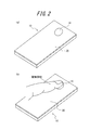
- FIG. 2 is a diagram illustrating an example of a usage state of the measurement apparatus 10.
- the measuring apparatus 10 includes a contact portion 14 on the back side of the main body 20 of the mobile phone.
- the subject measures the biological information with the measuring device 10 while pressing the finger of the hand, which is the subject site, against the contact portion 14.
- the biological information measured by the measuring device 10 can be any biological information that can be measured using the biological sensor 13.
- the measurement device 10 will be described below as an example of measuring the blood flow of a subject, which is information related to blood flow.
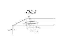
- FIG. 3 is a schematic enlarged perspective view showing a positional relationship among the illuminance measuring unit 111, the biosensor 13 and the contact unit 14 in the measuring apparatus 10.
- a transparent disk-shaped contact portion 14 is disposed on the back surface of the main body 20.
- the biosensor 13 and the illuminance measurement unit 111 are arranged in the vertical direction with respect to the back surface in the internal direction of the main body 20 from the contact unit 14.
- the biosensor 13 is disposed on a transparent disk-like base 17 provided between the contact unit 14 and the illuminance measurement unit 111, for example.
- the illuminance measurement unit 111 measures the illuminance of external light incident from the contact unit 14.
- the biosensor 13 emits measurement light to the test site that contacts the contact unit 14 and receives scattered light from the test site.
- the measurement apparatus 10 measures biological information based on the output (biological measurement output) acquired from the biological sensor 13.
- the illuminance measurement unit 111 constituting the contact state detection unit 11 measures the illuminance of external light incident from the contact unit 14.
- the illuminance measurement unit 111 is configured by a digital video camera, for example.
- the illuminance measurement unit 111 may be configured by an illuminance sensor using a phototransistor, a photodiode, or the like, for example.
- the illuminance measurement unit 111 will be described as a digital video camera.
- Information on the illuminance measured by the illuminance measurement unit 111 is transmitted to the control unit 15, and is used by the control unit 15 to determine a contact state of the test site with the contact unit 14.
- the notification unit 12 notifies information on the contact state of the test site in the contact unit 14 based on the control of the control unit 15.
- the information regarding the contact state includes, for example, information regarding the positional relationship between the test site and the contact portion 14.
- the measurement accuracy of the blood flow volume may change depending on the positional relationship between the biological sensor 13 and the test site. Therefore, it is preferable for the subject to arrange the test site at a suitable position with respect to the biosensor 13 so that the error in the blood flow measurement result falls within a predetermined error range.
- the notification unit 12 allows the subject to place the test site on the biosensor 13 at a suitable position on the contact unit 14. Notification.
- reporting part 12 can alert
- the notification unit 12 performs notification by a visual method
- the notification unit 12 performs notification by displaying an image or a character as a display device.
- reporting part 12 may alert
- the notification unit 12 performs notification by outputting an alarm sound, a voice guide, or the like as a sound generating device such as a speaker.
- the notification performed by the notification unit 12 is not limited to a visual or auditory method, and may be any method that can be recognized by the subject. Specific control of the notification unit 12 by the control unit 15 will be described later.
- the biological sensor 13 acquires biological information from the test site.
- the biological sensor 13 includes an emitting unit 21 and a light receiving unit 22.
- the emitting unit 21 emits laser light based on the control of the control unit 15.
- the emitting unit 21 emits laser light having a wavelength capable of detecting a predetermined component contained in blood, for example, as measurement light to a test site, and is configured by, for example, an LD (Laser Diode: Laser Diode). .
- LD Laser Diode: Laser Diode
- the light receiving unit 22 receives the scattered light of the measurement light from the test site as biological information.
- the light receiving unit 22 is configured by, for example, a PD (photodiode: Photo Diode).
- the biological sensor 13 transmits the photoelectric conversion signal (biological measurement output) of the scattered light received by the light receiving unit 22 to the control unit 15.
- the contact portion 14 is a portion in the measuring apparatus 10 that makes the subject contact a subject part such as a finger in order to measure biological information.
- the contact part 14 is comprised by the plate-shaped member, for example.
- the contact portion 14 is formed of a member that is transparent to at least the measurement light from the emission portion 21 and the scattered light from the contacted test site.
- the control unit 15 is a processor that controls and manages the entire measurement apparatus 10 including each functional block of the measurement apparatus 10.
- the control unit 15 includes a processor such as a CPU (Central Processing Unit) that executes a program defining a control procedure, and the program is stored in the storage unit 16 or an external storage medium, for example.
- a processor such as a CPU (Central Processing Unit) that executes a program defining a control procedure, and the program is stored in the storage unit 16 or an external storage medium, for example.
- CPU Central Processing Unit
- the control unit 15 determines the contact state of the site to be examined in the contact unit 14 based on the output from the contact state detection unit 11. In this Embodiment, the control part 15 judges the contact state of the test site
- the biosensor 13 when the test site is in contact with the contact unit 14 at the center of the contact unit 14. Therefore, it is considered that the measurement accuracy of blood flow is high. It is considered that the measurement accuracy of the blood flow rate is lowered as the location where the test site is in contact with the contact portion 14 is away from the center portion.
- the test site is closer to the peripheral portion of the contact portion 14, and the area where the test site covers the contact portion 14 becomes smaller.
- the illuminance of external light entering the illuminance measuring unit 111 from the contact unit 14 is increased. Therefore, when the illuminance measured by the illuminance measuring unit 111 is less than the first illuminance threshold, the control unit 15 is located at a position closer to the center than the predetermined range in the contact unit 14. In this case, it is determined that the region to be examined is in a position suitable for blood flow measurement. Conversely, when the illuminance measured by the illuminance measuring unit 111 is equal to or greater than the first illuminance threshold, the control unit 15 determines that the test site is not in a suitable position.
- the control unit 15 notifies the information on the determined contact state from the notification unit 12. For example, if the control unit 15 determines that the test site is in a suitable position, the control unit 15 may notify the notification unit 12 that the test site is in a suitable position. In this case, the control unit 15 may notify the start of measurement of blood flow from the notification unit 12.
- control unit 15 determines that the test site is not in a suitable position
- the control unit 15 notifies the notification unit 12 that the test site is not in a suitable position.
- the control unit 15 may perform a notification from the notification unit 12 to instruct the subject to move the test site to the center of the contact unit 14.
- the subject who has recognized the notification can move the position of the test site relative to the contact portion 14 and adjust the test site to be arranged at a suitable position.
- control unit 15 determines that the contact state is suitable for measurement of biological information
- the control unit 15 activates the biological sensor 13.
- the control unit 15 activates the biosensor 13 when determining that the test site is in a suitable position.
- the activated biosensor 13 acquires biometric information.
- the control unit 15 measures biological information based on the biological measurement output from the biological sensor 13. Specifically, the control unit 15 generates biological information based on the output from the light receiving unit 22.
- the control unit 15 emits laser light from the emitting unit 21 into the living tissue (test site) and receives scattered light scattered from the living tissue by the light receiving unit 22. . And the control part 15 calculates a blood flow rate based on the output regarding the received scattered light.
- the control unit 15 detects a beat signal (also referred to as a beat signal) generated by light interference between scattered light from a stationary tissue and scattered light from a moving blood cell.
- This beat signal represents the intensity as a function of time.
- the control part 15 makes this beat signal the power spectrum which represented power as a function of frequency.
- the Doppler shift frequency is proportional to the blood cell velocity, and the power corresponds to the amount of blood cells.
- the control part 15 calculates
- control unit 15 determines whether or not the acquisition of the biological information by the biological sensor 13 is finished. For example, the control unit 15 may determine that the acquisition of the biological information has ended after a predetermined time has elapsed since the biological sensor 13 started acquiring the biological information. Further, for example, the control unit 15 may determine that the acquisition of the biological information is completed when the biological sensor 13 acquires sufficient biological information for measuring the biological information.
- control unit 15 determines that the acquisition of the biological information has been completed, the control unit 15 stops the emission of the laser light from the emission unit 21.
- the control unit 15 may display the measured biological information on a display device or the like included in the measurement apparatus 10 configured by a known display such as a liquid crystal display, an organic EL display, or an inorganic EL display.
- the storage unit 16 can be composed of a semiconductor memory, a magnetic memory, or the like, and stores various information, a program for operating the measuring apparatus 10, and the like, and also functions as a work memory.
- the storage unit 16 stores, for example, a first illuminance threshold that serves as a reference for the control unit 15 to determine the position of the test site.
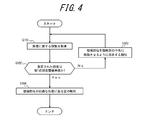
- FIG. 4 is a flowchart illustrating an example of processing (contact position adjustment processing) performed by the control unit 15 to adjust the contact position of the test site.
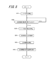
- FIG. 5 is a flowchart illustrating an example of the biological information measurement process performed by the control unit 15. The control unit 15 starts the flow of FIG. 4 when, for example, the subject operates the measurement device 10 and the measurement device 10 becomes capable of measuring biological information.
- the control unit 15 acquires information on the illuminance measured by the illuminance measurement unit 111 (step S101).
- the control unit 15 refers to the storage unit 16 and determines whether or not the measured illuminance is less than the first illuminance threshold (step S102).
- control unit 15 determines that the measured illuminance is greater than or equal to the first illuminance threshold value (No in step S102)
- the control unit 15 determines that the test site is not in a suitable position in the contact unit 14, and notifies the notification unit 12 From this, a notification is given to instruct the subject to move the test site to the center of the contact portion 14 (step S103).
- the subject who has recognized the notification moves the position of the test site with respect to the contact portion 14 and adjusts the test site to be arranged at a suitable position. Then, this flow moves to step S101.
- control unit 15 determines that the measured illuminance is less than the first illuminance threshold (Yes in step S102)
- the control unit 15 determines that the test site is in a suitable position in the contact unit 14.
- the control unit 15 notifies the notification unit 12 that the test site is in a suitable position in the contact unit 14 (step S104), and ends this flow.
- control unit 15 starts the measurement process flow shown in FIG. 5 and measures biological information.
- the control unit 15 emits laser light from the emitting unit 21 (step S201). Acquisition of biological information by the biological sensor 13 is started by the emission of the laser light.
- the control unit 15 determines whether or not the biometric information has been acquired by the biosensor 13 (step S202).
- control unit 15 determines that the acquisition of biometric information has not ended (No in step S202), the control unit 15 repeats step S202 until it determines that the acquisition of biometric information has ended.
- control unit 15 determines that the acquisition of the biological information has been completed (Yes in step S202)
- the control unit 15 stops the emission of the laser light from the emission unit 21 (step S203).
- control unit 15 acquires an output related to biological information acquired by the biological sensor 13, that is, a biological measurement output from the biological sensor 13 (step S204).
- the control unit 15 measures biological information based on the biological measurement output acquired from the biological sensor 13 (step S205).
- the control unit 15 displays the measurement result of the measured biological information on the display device (step S206).
- the subject can know the blood flow volume by confirming the displayed measurement result.
- the control unit 15 determines the contact state of the test site in the contact unit 14 based on the illuminance measured by the illuminance measurement unit 111.
- the control unit 15 determines that the test site is not in a suitable position for measurement of biological information in the contact unit 14, the control unit 15 notifies the test subject of information related to the contact state. Therefore, since the subject can adjust the position of the test site according to the notification, it becomes easy to adjust the contact state of the test site to a suitable position for measuring biological information.
- the measuring apparatus 10 can improve the measurement accuracy of biological information.
- control unit 15 emits a laser beam from the emitting unit 21 when the test site is arranged at a suitable position, and stops the emission of the laser beam when the acquisition of the biological information is completed. Thereby, the control part 15 can suppress the unnecessary power consumption of the measuring apparatus 10.
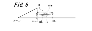
- FIG. 6 is a schematic enlarged perspective view showing a positional relationship among the contact state detection unit 11, the biosensor 13 and the contact unit 14 in the measurement apparatus 10 according to the second embodiment of the present invention.
- the contact state detection unit 11 includes a plurality of illuminance measurement units 111 configured by, for example, an illuminance sensor.
- the plurality of illuminance measuring units 111 are arranged around the biosensor 13.
- description of the same points as in the first embodiment will be omitted, and different points will be described.
- a transparent disk-shaped contact portion 14 is disposed on the back surface of the main body 20 of the mobile phone.
- the biosensor 13 is disposed at a position facing the central portion of the contact portion 14.
- four illuminance measuring units 111a, 111b, 111c, and 111d are arranged at equal intervals on the periphery of the contact unit 14. In the case where the four illuminance measurement units 111a, 111b, 111c, and 111d are not distinguished from each other, they are hereinafter referred to as the illuminance measurement unit 111.
- the quantity of the illuminance measurement unit 111 included in the measurement apparatus 10 may be any number.
- the illuminance measurement unit 111 is an arbitrary position as long as the position at which the test site is in contact with the contact unit 14 can determine whether or not the position relative to the biosensor 13 is suitable for measurement of biometric information. It may be arranged in a position. The position where it can be determined whether or not it is suitable for the measurement of biological information is, for example, the vicinity of the biological sensor 13.
- the number and arrangement of the illuminance measurement units 111 are not limited to the case where the four illuminance measurement units 111 are arranged at equal intervals as described above, and the number and arrangement may be changed as appropriate.
- illuminance measuring units 111 are arranged on the side where the base of the finger is located. You may control each function part so that a test site
- reporting part 12 adds the information regarding the pressure which a test site
- the pressure at which the test site contacts the contact portion 14 is preferably such that the error in the blood flow measurement result falls within a predetermined error range based on, for example, a statistical relationship between the pressure and the blood flow measurement error. It is preferable to be included in the range of pressure.
- the control unit 15 determines the contact state of the site to be examined in the contact unit 14 based on information on the illuminance measured by each of the plurality of illuminance measurement units 111. For example, when the illuminance measured by each of the plurality of illuminance measuring units 111 is less than the second illuminance threshold, the control unit 15 determines that the test site is in a state suitable for measuring blood flow. Because, when the illuminance measured by the four illuminance measuring units 111 is less than the second illuminance threshold value, the test site covers the biosensor 13 located at the center of the four illuminance measuring units 111.
- the control unit 15 may notify the notification unit 12 that the test site is in a suitable position. In this case, the control unit 15 may notify the start of measurement of blood flow from the notification unit 12.
- the control unit 15 determines that the test site is not in a state suitable for blood flow measurement. In this case, the control unit 15 determines in more detail the contact state of the test site by determining whether the illuminance measured by each of the plurality of illuminance measurement units 111 is equal to or greater than the third illuminance threshold. I can judge.
- the contact pressure at which the test site contacts the contact portion 14 may have an appropriate pressure range suitable for blood flow measurement. For example, when the contact pressure at the contact portion 14 is too weak, the measuring apparatus 10 may not be able to measure accurate biological information due to the influence of noise.
- the control unit 15 can determine the state related to the contact pressure based on the output of the illuminance measurement unit 111. Further, the control unit 15 can determine, for example, in which direction the test site is preferably moved based on the output of the illuminance measurement unit 111. Hereinafter, detailed determination performed by the control unit 15 will be described.
- the third illuminance threshold value can be an appropriate value that is equal to or greater than the second illuminance threshold value.
- the control unit 15 when the illuminance measured by each of the plurality of illuminance measuring units 111 is all equal to or greater than the third illuminance threshold, the control unit 15 is located at the center of the four illuminance measuring units 111. However, it can be determined that the contact pressure at which the test site contacts the contact portion 14 is weak. This is because when the illuminance measured by each of the plurality of illuminance measuring units 111 is all equal to or greater than the third illuminance threshold, all the illuminance measuring units 111 are not sufficiently covered with the test site. In this case, the control unit 15 notifies the notification unit 12 that the region to be examined should be brought into contact with the contact unit 14 more strongly. When the subject who has confirmed the notification increases the contact pressure and the illuminance measured by the illuminance measurement unit 111 becomes lower than the third illuminance threshold, the control unit 15 measures the biological information by the contact pressure. It is judged to be strong enough.
- the control unit 15 specifies the illuminance measurement unit 111 that measures the highest illuminance among the four illuminance measurement units 111.
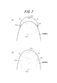
- FIG. 7 is a diagram schematically illustrating an example of the contact state of the test site in the contact portion 14.
- FIG. 7 is a view of the contact state of the test site as viewed from the back side of the main body 20, and shows only the illuminance measurement unit 111, the biosensor 13, the contact unit 14, and the test site.
- the illuminance measurement unit 111c is covered with the test site, and thus measures the lowest illuminance.
- the illuminance measurement units 111b and 111d measure the illuminance according to the external light incident from the portion of the contact unit 14 that is not covered with the test site.
- the illuminance measurement unit 111a is not covered with the test site, and measures the highest illuminance among the four illuminance measurement units 111a, 111b, 111c, and 111d.
- the illuminance measurement unit 111a that measures the highest illuminance is not covered by the test site or is covered by the test site most of the four illuminance measurement units 111 depending on the position of the test site. The area is considered small.
- the control unit 15 determines that the test site is biased in contact with the opposite direction of the specified illuminance measurement unit 111a, that is, in the direction of the illuminance measurement unit 111c, with the biosensor 13 interposed therebetween in the contact unit 14. To do. In this case, the control unit 15 notifies the notification unit 12 that the test site should be moved in the direction of the specified illuminance measurement unit 111a with the biosensor 13 interposed therebetween.
- the control unit 15 can determine that the test site has been adjusted to move to the center of the contact unit 14.
- the control unit 15 is based on the illuminance measured by each of the illuminance measurement units 111 using a predetermined algorithm, for example. By performing weighting, the direction in which the test site is moved and the distance to be moved may be calculated in order to obtain an appropriate contact state. For example, in the example of FIG. 7A, the control unit 15 performs weighting based on the illuminances measured by the four illuminance measurement units 111a, 111b, 111c, and 111d, and the contact state shown in FIG. 7B.
- the control unit 15 notifies the calculated result from the notification unit 12.
- the control unit 15 determines that the test site is a contact unit. 14 can be determined to have been adjusted so as to move to the central portion of 14.
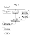
- control unit 15 starts the flow of FIG. 8 when, for example, the subject operates the measuring device 10 and the measuring device 10 can measure biological information.
- the control unit 15 acquires information on the illuminance measured by the four illuminance measuring units 111 (step S301).
- the control unit 15 determines whether or not the illuminance measured by each of the four illuminance measurement units 111 is less than the second illuminance threshold (step S302).
- control unit 15 determines that at least one of the illuminances is equal to or greater than the second illuminance threshold (No in step S302), the illuminances measured by the four illuminance measurement units 111 are all third. It is determined whether or not the illumination threshold value is exceeded (step S303).
- step S303 When the control unit 15 determines that the illuminances measured by each of the four illuminance measurement units 111 are all equal to or greater than the third illuminance threshold (Yes in step S303), the contact pressure at the test site in the contact unit 14 is weak. It is judged that the contact pressure should be increased from the notification unit 12 (step S304). Then, the flow moves to step S301.
- control unit 15 determines that at least one of the illuminances is less than the third illuminance threshold (No in step S303), the control unit 15 determines that the test site is not in contact with the central portion of the contact unit 14, and Among the illuminance measuring units 111, the illuminance measuring unit 111 that measures the highest illuminance is specified (step S305).
- the control unit 15 notifies the notification unit 12 that the region to be examined should be moved in the direction of the illuminance measurement unit 111 specified when the highest illuminance is measured (step S306). Then, the flow moves to step S301.
- step S302 When the control unit 15 determines in step S302 that all the illuminances measured by the four illuminance measurement units 111 are less than the second illuminance threshold value (Yes in step S302), the contact state of the test site is preferable. Is notified from the notification unit 12 (step S307), and this flow ends.
- control unit 15 starts the measurement process flow shown in FIG. 5 and measures biological information.
- the control unit 15 determines the contact state of the test site in the contact unit 14 based on the illuminance measured by the plurality of illuminance measurement units 111.
- the control unit 15 determines whether the contact pressure is weak or the position of the test site is not appropriate based on the illuminance measured by the plurality of illuminance measurement units 111, The determined result is notified.
- the control unit 15 can notify which direction the test site should be moved. Therefore, since the subject can adjust the position of the test site according to the notification, it becomes easy to adjust the contact state of the test site to a suitable position for measuring biological information.
- the measuring apparatus 10 can improve the measurement accuracy of biological information.
- FIG. 9 is a schematic enlarged perspective view showing the positional relationship among the contact state detection unit 11, the biosensor 13 and the contact unit 14 in the measurement apparatus 10 according to the third embodiment of the present invention.
- the contact state detection unit 11 includes, for example, a plurality of strain sensors. The plurality of strain sensors are arranged around the biosensor 13.
- a transparent disk-shaped contact portion 14 is disposed on the back surface of the main body 20 of the mobile phone.
- the contact part 14 is comprised by the member which has flexibility.
- Four strain sensors 112a, 112b, 112c, and 112d are arranged at equal intervals on the peripheral edge of the contact portion. In the case where the four strain sensors 112a, 112b, 112c, and 112d are not distinguished from each other, they are hereinafter referred to as strain sensors 112.
- the measuring apparatus 10 in the present embodiment includes a support plate 18 that supports the biosensor 13 inside the main body 20.
- the support plate 18 is composed of a member that is transparent at least with respect to the measurement light from the emitting portion 21 and the scattered light from the contacted test site.
- a biosensor 13 is disposed at a position facing the central portion of the support plate 18.
- Each strain sensor 112 detects the distortion of the contact portion 14 caused by the pressure applied to the contact portion 14 when the subject brings the test portion into contact with the contact portion 14.
- Each strain sensor 112 is configured by, for example, a piezoelectric element that detects information regarding strain caused by pressing as a voltage.
- the piezoelectric element may be, for example, a unimorph, bimorph, or multilayer piezoelectric element.
- the strain sensor 112 is not limited to a piezoelectric element, and any strain sensor capable of detecting the strain of the contact portion 14 such as a semiconductor strain sensor or a resistor strain sensor can be used.
- the number of strain sensors 112 included in the measuring apparatus 10 may be any number.
- the strain sensor 112 may be in any position as long as the position where the test site is in contact with the contact portion 14 can determine whether or not the position to be measured is suitable for measurement of biological information in the positional relationship with the biological sensor 13. May be arranged.
- the position where it can be determined whether or not it is suitable for the measurement of biological information is, for example, the vicinity of the biological sensor 13.
- the number and arrangement of the strain sensors 112 are not limited to the case where the four strain sensors 112 are arranged at equal intervals as described above, and the number and arrangement may be changed as appropriate.
- strain sensors 112 are arranged on the side where the base of the finger is located.
- Each functional unit may be controlled so that the test site is appropriately brought into contact with the contact unit 14.
- reports the information regarding the positional relationship between a test site
- the pressure at which the test site contacts the contact portion 14 is preferably such that the error in the blood flow measurement result falls within a predetermined error range based on, for example, a statistical relationship between the pressure and the blood flow measurement error. It is preferable to be included in the range of pressure.
- the control unit 15 determines the contact state of the region to be examined in the contact unit 14 based on information on the strain detected by each of the plurality of strain sensors 112. For example, when all the strain amounts detected by the plurality of strain sensors 112 are equal to or greater than the first strain amount threshold value, the control unit 15 determines that the test site is in a state suitable for blood flow measurement. . Because, when all the strain amounts detected by the four strain sensors 112 are equal to or greater than the first strain amount threshold value, the test site covers the biosensor 13 located at the center of the four strain sensors 112. This is because it can be determined that the positional relationship between the biosensor 13 and the region to be examined is suitable for measuring blood flow. When it is determined that the test site is in a state suitable for blood flow measurement, the control unit 15 may notify the notification unit 12 that the test site is in a suitable position. In this case, the control unit 15 may notify the start of measurement of blood flow from the notification unit 12.
- the control unit 15 determines that the test site is not in a state suitable for blood flow measurement. In this case, the control unit 15 determines whether or not the amount of strain detected by each of the plurality of strain sensors 112 is less than the second strain amount threshold value, so that the contact state of the site to be examined is more detailed. Can be judged.
- the contact pressure at which the test site contacts the contact portion 14 may have an appropriate pressure range suitable for blood flow measurement. For example, when the contact pressure at the contact portion 14 is too weak, the measuring apparatus 10 may not be able to measure accurate biological information due to the influence of noise.
- the control unit 15 can determine the state related to the contact pressure based on the output of the strain sensor 112. Further, the control unit 15 can determine, for example, in which direction the test site is preferably moved based on the output of the strain sensor 112. Hereinafter, detailed determination performed by the control unit 15 will be described.
- the second distortion amount threshold value can be an appropriate value equal to or less than the first distortion amount threshold value.
- the control unit 15 when all of the strain amounts detected by the plurality of strain sensors 112 are less than the second strain amount threshold value, the control unit 15 is located at the center of the four strain sensors 112. However, it can be determined that the contact pressure at which the test site contacts the contact portion 14 is weak. This is because when all the strain amounts detected by the plurality of strain sensors 112 are less than the second strain amount threshold value, all the strain sensors 112 are not sufficiently pressed by the test site. In this case, the control unit 15 notifies the notification unit 12 that the region to be examined should be brought into contact with the contact unit 14 more strongly. When the subject who has confirmed the notification increases the contact pressure and the strain amount detected by the strain sensor 112 is equal to or greater than the second strain amount threshold, the control unit 15 measures the biological information. It is judged to be strong enough.
- the control unit 15 detects the strain sensor 112 that has detected the strain amount greater than or equal to the second strain amount threshold. Since it is pressed by the test site, it is determined that a strain amount equal to or greater than the second strain amount threshold is detected. In this case, the control unit 15 specifies the strain sensor 112 that detects the lowest strain amount among the four strain sensors 112.
- FIG. 10 is a diagram schematically illustrating an example of a contact state of a test site in the contact portion 14.
- FIG. 10 is a view of the contact state of the test site as viewed from the back side of the main body 20, and shows only the strain sensor 112, the biosensor 13, the contact portion 14, and the test site.
- the strain sensor 112c is pressed by the region to be examined, and thus detects the largest amount of strain.
- the strain sensors 112b and 112d detect the amount of strain due to the pressing of the test site, but since the pressing force applied to the strain sensors 112b and 112d from the test site is smaller than the pressing force applied to the strain sensor 112c, the strain sensor 112b. And 112d are smaller than the strain detected by the strain sensor 112c. Since the strain sensor 112a is not pressed by the region to be examined, it does not detect strain. Thus, the strain sensor 112 a that detects the smallest strain amount is not pressed by the region to be examined, or is not subjected to the most pressing force among the four strain sensors 112.
- the control unit 15 determines that the test site is biased in contact with the opposite direction of the specified strain sensor 112a, that is, the direction of the strain sensor 112c, with the biosensor 13 interposed therebetween in the contact unit 14. In this case, the control unit 15 notifies the notification unit 12 that the test site should be moved in the direction of the specified strain sensor 112a with the biosensor 13 interposed therebetween.
- the control unit 15 can determine that the test site has been adjusted to move to the center of the contact unit 14.
- the control unit 15 uses, for example, a predetermined algorithm to set the strain amount detected by each strain sensor 112. By performing weighting based on this, the direction in which the test site is moved and the distance to be moved may be calculated in order to obtain an appropriate contact state. For example, in the example of FIG. 10A, the control unit 15 performs weighting based on the strain amounts detected by the four strain sensors 112a, 112b, 112c, and 112d, and the contact state illustrated in FIG. In order to achieve this, the direction in which the test site is moved and the distance to be moved are calculated. The control unit 15 notifies the calculated result from the notification unit 12.
- the control unit 15 determines that the test site is a contact unit. 14 can be determined to have been adjusted so as to move to the central portion of 14.
- control unit 15 in the third embodiment will be described with reference to the flowchart shown in FIG.
- the control unit 15 starts the flow of FIG.
- the control unit 15 acquires information related to the strain detected by the four strain sensors 112 (step S401).
- the control unit 15 determines whether or not the strain amounts detected by the four strain sensors 112 are all equal to or greater than the first strain amount threshold value (step S402).
- the control unit 15 determines that at least one of the distortion amounts is less than the first distortion amount threshold (No in step S402), the distortion amounts detected by the four strain sensors 112 are all first. It is determined whether or not the distortion amount threshold value is less than 2 (step S403).
- step S403 When the control unit 15 determines that the strain amounts detected by the four strain sensors 112 are all less than the second strain amount threshold value (Yes in step S403), the contact pressure of the test site in the contact unit 14 is increased. It judges that it is weak, and alert
- control unit 15 determines that at least one of the distortion amounts is equal to or greater than the second distortion amount threshold (No in step S403), the control unit 15 determines that the test site is not in contact with the central portion of the contact unit 14, Among the four strain sensors 112, the strain sensor 112 that detects the smallest strain amount is specified (step S405).
- the control unit 15 notifies the notification unit 12 that the region to be examined should be moved in the direction of the strain sensor 112 specified when the smallest amount of distortion is detected (step S406). Then, the flow moves to step S401.
- control unit 15 determines in step S402 that all the strain sensors detected by each of the four strain sensors 112 are equal to or greater than the first strain amount threshold value (Yes in step S402), the contact state of the test site is determined.
- the notification unit 12 notifies that it is suitable (step S407), and ends this flow.
- control unit 15 starts the measurement processing flow shown in FIG. 5 and measures biological information.
- the control unit 15 determines the contact state of the test site in the contact unit 14 based on the strain amounts detected by the plurality of strain sensors 112. When determining that the contact state is not suitable, the control unit 15 determines whether the contact pressure is weak or the position of the test site is not appropriate based on the amount of strain detected by the plurality of strain sensors 112, and the like. The determined result is notified. Furthermore, when it is determined that the position of the test site is not appropriate, the control unit 15 can notify which direction the test site should be moved. Therefore, since the subject can adjust the position of the test site according to the notification, it becomes easy to adjust the contact state of the test site to a suitable position for measuring biological information. Thus, the measuring apparatus 10 can improve the measurement accuracy of biological information.
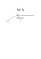
- FIG. 12 is a schematic enlarged perspective view showing the positional relationship between the contact state detection unit 11 and the biosensor 13 in the measurement apparatus 10 according to the fourth embodiment of the present invention.
- the contact state detection unit 11 is configured as a touch panel.
- the touch panel 113 also functions as the contact unit 14 that contacts the test site when the test subject uses the measuring apparatus 10 to measure the biological information.
- the touch panel 113 detects contact by the subject's test site on the touch surface.
- the touch panel 113 detects, as information on the contact state, a region where the test site contacts the touch surface as a contact position.
- the touch panel 113 notifies the control unit 15 of information related to the detected contact position of the test site.
- a disk-shaped touch panel 113 is disposed on the back surface of the main body 20 of the mobile phone.
- the touch panel 113 can be configured by a known method such as a resistance film method, a capacitance method, and an optical method.
- the touch panel 113 is composed of a member that is transparent at least with respect to the measurement light from the emitting portion 21 and the scattered light from the contacted test site.
- the control unit 15 determines whether or not the contact position of the test site is a suitable position for measuring the blood flow based on the information related to the contact position of the test site output from the touch panel 113. . For example, the control unit 15 determines that the test site is in a position suitable for blood flow measurement when the test site is located closer to the central part where the biosensor 13 is disposed than a predetermined range in the contact unit 14. To do. Control part 15 judges that it is not in a suitable position, when a tested part is in a position away from the central part rather than the predetermined range. The control unit 15 notifies the information about whether or not the contact position of the test site is a suitable position for blood flow measurement from the notification unit 12.
- the control unit 15 determines the direction in which the subject should move the test site in order to place the test site at a suitable position. And the distance to be moved. Then, the control unit 15 notifies the calculated result from the notification unit 12.
- the touch panel 113 detects the movement of the test site and notifies the control unit 15 of information related to the contact position of the test site. Based on the information regarding the contact position acquired from the touch panel 113, the control unit 15 determines whether or not the test site has become a suitable position for blood flow measurement.
- control unit 15 determines that the test site is not in a suitable position for measuring blood flow, the subject should move the test site in order to place the test site in a suitable position. The direction and the distance to be moved are calculated, and the calculation result is notified from the notification unit 12. On the other hand, when the control unit 15 determines that the test site is in a position suitable for blood flow measurement, the control unit 15 notifies the notification unit 12 that the position of the test site is preferable.
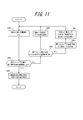
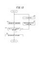
- control unit 15 in the fourth embodiment will be described with reference to the flowchart shown in FIG.
- the control unit 15 starts the flow of FIG.
- the control unit 15 acquires information regarding the contact position detected by the touch panel 113 (step S501).
- the control unit 15 determines whether or not the contact position of the test site detected by the touch panel 113 is a position suitable for blood flow measurement (step S502).
- control unit 15 determines that the contact position of the test site is not a suitable position (No in step S502), the control unit 15 calculates a direction and a distance to move the test site in order to make the contact position a suitable position ( Step S503).
- reports the calculation result in step S503 from the alerting
- the subject who has confirmed the notification can easily place the test site at a suitable position by moving the test site based on the notification content. Then, the flow moves to step S501.
- step S502 when the control unit 15 determines that the contact position of the test site is a suitable position (Yes in step S502), the control unit 15 notifies the notification unit 12 that the contact position of the test site is preferable. (Step S505), this flow is finished.
- control unit 15 starts the measurement process flow shown in FIG. 5 and measures the biological information.
- the control unit 15 determines the contact state of the test site based on the contact position of the test site detected by the touch panel 113.
- the control part 15 can alert
- each component, each step, etc. can be rearranged so that there is no logical contradiction, and multiple components, steps, etc. can be combined or divided into one It is.
- the control unit 15 determines that the contact state is suitable when the illuminance measured by the illuminance measurement unit 111 is less than the first illuminance threshold.
- the determination of the contact state performed by is not limited to this.
- the control unit 15 may determine the contact state based on a fourth illuminance threshold value that is higher than the first illuminance threshold value. For example, when the illuminance measured by the illuminance measurement unit 111 is equal to or greater than the fourth illuminance threshold, the control unit 15 has a lot of external light incident from the contact unit 14 and the contact unit 14 is sufficiently covered by the test site. Judge that there is no. In this case, the control unit 15 determines that the contact pressure of the test site in the contact unit 14 is weak, and notifies the notification unit 12 that the contact pressure should be increased.
- the fourth illuminance threshold is stored in the storage unit 16, for example.
- control unit 15 may determine the contact state of the test site based on an image captured by a camera that is the illuminance measurement unit 111. Specifically, the control unit 15 can determine the positional relationship between the test site and the biological sensor 13 based on the position of the test site reflected in the camera. The control unit 15 may determine the contact pressure of the test site based on the area of the test site reflected in the camera.
- control unit 15 may further determine the contact state based on a fifth illuminance threshold value that is lower than the second illuminance threshold value.
- the control unit 15 may determine whether or not the illuminances measured by the four illuminance measurement units 111 are all less than the fifth illuminance threshold.
- the controller 15 determines that the illuminance measured by each of the four illuminance measuring units 111 is less than the fifth illuminance threshold, the contact pressure is strong, and the capillaries at the test site are crushed. It is determined that the contact state is not suitable for measurement of biological information. In this case, the control unit 15 may notify the notification unit 12 that the contact pressure should be reduced.
- the fifth illuminance threshold is stored in the storage unit 16, for example.
- control unit 15 may further determine the contact state based on a third distortion amount threshold value that is larger than the first distortion amount threshold value.
- the control unit 15 may determine whether or not the strain amounts detected by the four strain sensors 112 are all equal to or greater than the third strain amount threshold value.
- the control unit 15 determines that the strain amounts detected by the four strain sensors 112 are all equal to or greater than the third strain amount threshold value, the contact pressure is strong and the capillaries at the site to be examined are crushed. It is determined that the contact state is not suitable for the measurement of biological information. In this case, the control unit 15 may notify the notification unit 12 that the contact pressure should be reduced.
- the third distortion amount threshold value is stored in the storage unit 16, for example.
- the contact part 14 was disk shape and demonstrated that the some illumination intensity measurement part 111 was arrange
- the contact portion 14 may have a shape other than the disc shape.
- the plurality of illuminance measuring units 111 may be arranged at arbitrary positions where it can be determined whether or not the measurement is suitable for the measurement of biological information based on the positional relationship with the biological sensor 13.
- the contact part 14 may be a rectangle, and the plurality of illuminance measurement parts 111 may be arranged on the same circumference with the biosensor 13 as the center. The same applies to the shape of the contact portion 14 and the arrangement of the plurality of strain sensors 112 in the third embodiment.
- the touch panel 113 in the fourth embodiment is not limited to a disk shape, but may be an arbitrary shape.
- the contact state detection unit 11 is the illuminance measurement unit 111, the strain sensor 112, or the touch panel 113 . It is not limited to these.
- the contact state detection unit 11 can have an arbitrary configuration capable of detecting the contact state of the test site in the contact unit 14.
- the contact state detection part 11 can be comprised by temperature sensors, such as a thermocouple, for example.
- the control unit 15 determines the contact state based on the temperature change detected by the plurality of temperature sensors.
- the contact state detection part 11 may be configured by combining the illuminance measurement unit 111, the strain sensor 112, or the touch panel 113.
- the contact state detection unit 11 may be configured by the two illuminance measurement units 111 and the two strain sensors 112, or may be configured by a part of the strain sensor 112 and the other part of the touch panel 113. . In this way, the contact state detection unit 11 can be configured by combining the illuminance measurement unit 111, the strain sensor 112, or the touch panel 113 in an appropriate number and arrangement.
- control unit 15 may continuously determine the contact state of the test site while the biosensor 13 is acquiring biometric information.
- the control unit 15 determines that the contact state is not suitable while the biosensor 13 is acquiring biometric information, the control unit 15 stops the emission of the laser light from the emission unit 21. In this way, the control unit 15 can suppress unnecessary power consumption of the measuring apparatus 10.
- the control unit 15 included in the measurement device 10 generates biological information based on the output of the light receiving unit 22.
- generation of biological information is controlled by the measurement device 10. It is not restricted to the case where the part 15 performs.
- a server device connected to the measurement device 10 via a wired or wireless network or a combination thereof includes a functional unit corresponding to the control unit 15, and biometric information is generated by the server device having this functional unit. It may be done.
- the measuring apparatus 10 acquires a biometric output by the biosensor 13 and transmits the acquired biometric output to the server apparatus from a communication unit that is separately provided.
- the server device generates biological information based on the biological measurement output, and transmits the generated biological information to the measuring device 10.
- the user can browse the biometric information received by the measurement apparatus 10 by displaying the biometric information on the display device.
- the measurement device 10 can be reduced in size and the like as compared with the case where all the functional units illustrated in FIG. 1 are realized on one measurement device 10. .
Abstract
A measurement device for measuring biological information upon bringing a subject site into contact with a contact part (14), the measurement device being provided with: a contact state detection unit (11) for detecting the contact state of the subject site at the contact part (14); a biological sensor (13) for acquiring biological information from the subject site; a notification unit (12); and a control unit (15) for measuring the biological information on the basis of output from the biological sensor (13). The control unit (15) determines the contact state of the subject site at the contact part (14) on the basis of output from the contact state detection unit (11) and issues information relating to the contact state from the notification unit (12).
Description
本出願は、日本国特許出願2014-129206号(2014年6月24日出願)及び日本国特許出願2014-217402号(2014年10月24日出願)の優先権を主張するものであり、当該出願の開示全体を、ここに参照のために取り込む。
This application claims the priority of Japanese Patent Application No. 2014-129206 (filed on June 24, 2014) and Japanese Patent Application No. 2014-217402 (filed on October 24, 2014). The entire disclosure of the application is hereby incorporated by reference.
本発明は、測定装置及び測定方法に関する。
The present invention relates to a measuring apparatus and a measuring method.
従来、被検者(ユーザ)の指先等の被検部位から生体出力情報を取得して生体情報を測定する測定装置が知られている。例えば、生体情報として血流を測定する血流測定装置は、レーザ光を指先に照射し、指先の毛細血管の血流からの散乱光に基づいて血流を測定する(例えば、特許文献1参照)。
2. Description of the Related Art Conventionally, a measuring apparatus that acquires biological output information from a test site such as a fingertip of a subject (user) and measures the biological information is known. For example, a blood flow measuring device that measures blood flow as biological information irradiates a fingertip with a laser beam and measures blood flow based on scattered light from blood flow of capillaries at the fingertip (see, for example, Patent Document 1). ).
生体情報の測定精度は、測定装置に対する被検部位の接触状態により変化する。しかし、生体情報の測定に関する専門知識を有さない被検者が、被検部位を適切な状態で測定装置に接触させることは困難である。測定装置は、生体情報を高い精度で測定するために、被検者に適切な接触状態で被検部位を接触させることが望ましい。
The measurement accuracy of biological information varies depending on the contact state of the test site with respect to the measurement device. However, it is difficult for a subject who does not have expertise related to measurement of biological information to bring the test site into contact with the measurement device in an appropriate state. In order to measure the biological information with high accuracy, it is desirable that the measurement device causes the subject to contact the subject in an appropriate contact state.
かかる事情に鑑みてなされた本発明の目的は、生体情報の測定精度を向上可能な測定装置及び測定方法を提供することにある。
An object of the present invention made in view of such circumstances is to provide a measuring apparatus and a measuring method capable of improving the measurement accuracy of biological information.
上記課題を解決するため、本発明に係る測定装置は、
被検部位を接触部に接触させて生体情報を測定する測定装置であって、
前記接触部における前記被検部位の接触状態を検出する接触状態検出部と、
前記被検部位から生体情報を取得する生体センサと、
報知部と、
前記生体センサの出力に基づいて前記生体情報を測定する制御部と、を備え、
前記制御部は、前記接触状態検出部からの出力に基づいて、前記接触部における前記被検部位の前記接触状態を判断し、前記接触状態に関する情報を前記報知部から報知させる。 In order to solve the above problems, a measuring apparatus according to the present invention provides:
A measuring device for measuring biological information by bringing a test site into contact with a contact part,
A contact state detection unit for detecting a contact state of the test site in the contact unit;
A biological sensor for acquiring biological information from the test site;
A notification unit;
A control unit that measures the biological information based on the output of the biological sensor,
The control unit determines the contact state of the test site in the contact unit based on an output from the contact state detection unit, and causes the notification unit to report information on the contact state.
前記制御部は、前記接触状態が前記生体情報の測定に適していると判断すると、前記生体センサを起動してもよい。
The control unit may activate the biological sensor when determining that the contact state is suitable for the measurement of the biological information.
前記接触状態に関する情報は、前記被検部位が前記接触部に接触する圧力に関する情報及び/又は前記被検部位と前記接触部との位置関係に関する情報を含んでいてもよい。
The information relating to the contact state may include information relating to the pressure at which the test site contacts the contact portion and / or information relating to the positional relationship between the test site and the contact portion.
前記接触状態検出部は照度測定部を備え、
前記制御部は、前記照度測定部が測定した照度に関する情報の出力に基づいて前記接触状態を判断してもよい。 The contact state detection unit includes an illuminance measurement unit,
The said control part may judge the said contact state based on the output of the information regarding the illumination intensity which the said illumination intensity measurement part measured.
前記照度測定部は、当該測定装置において前記生体センサの周囲に複数配置され、
前記制御部は、前記複数の照度測定部のそれぞれが測定した照度に関する情報の出力に基づいて前記接触状態を判断してもよい。 A plurality of the illuminance measurement units are arranged around the biosensor in the measurement device,
The control unit may determine the contact state based on an output of information related to illuminance measured by each of the plurality of illuminance measurement units.
前記複数の照度測定部は、前記生体センサを中心とした同一円周上に配置されていてもよい。
The plurality of illuminance measuring units may be arranged on the same circumference centered on the biological sensor.
前記制御部は、前記複数の照度測定部のそれぞれが測定した照度が所定の照度閾値以上である場合、前記被検部位が前記接触部に接触する圧力を強くすべき旨を前記報知部から報知させてもよい。
When the illuminance measured by each of the plurality of illuminance measurement units is equal to or greater than a predetermined illuminance threshold, the control unit notifies the notification unit that the pressure at which the test site contacts the contact portion should be increased. You may let them.
前記制御部は、前記複数の照度測定部のいずれかが測定した照度が所定の照度閾値未満である場合、前記複数の照度測定部のうち、最も高い照度を測定する照度測定部を特定し、当該特定した照度測定部の方向へ被検部位を移動すべき旨を前記報知部から報知させてもよい。
When the illuminance measured by any of the plurality of illuminance measurement units is less than a predetermined illuminance threshold, the control unit identifies an illuminance measurement unit that measures the highest illuminance among the plurality of illuminance measurement units, You may make it alert | report that the to-be-tested part should be moved to the direction of the specified said illumination intensity measurement part from the said alerting | reporting part.
前記接触状態検出部は、前記生体センサの周囲に配置された複数の歪センサを備え、
前記制御部は、前記複数の歪センサのそれぞれが検出した前記接触部の歪みに関する情報の出力に基づいて前記接触状態を判断してもよい。 The contact state detection unit includes a plurality of strain sensors arranged around the biosensor,
The control unit may determine the contact state based on an output of information related to distortion of the contact unit detected by each of the plurality of strain sensors.
前記制御部は、前記複数の歪センサのそれぞれが検出した歪み量が所定の歪み量閾値未満である場合、前記被検部位が前記接触部に接触する圧力を強くすべき旨を前記報知部から報知させてもよい。
When the strain amount detected by each of the plurality of strain sensors is less than a predetermined strain amount threshold, the control unit informs that the pressure at which the test site is in contact with the contact portion should be increased from the notification unit. You may make it alert | report.
前記制御部は、前記複数の歪センサのいずれかが検出した歪み量が所定の歪み量閾値以上である場合、前記複数の歪センサのうち、最も小さい歪み量を検出する歪センサを特定し、当該特定した歪センサの方向へ被検部位を移動すべき旨を前記報知部から報知させてもよい。
The control unit, when the amount of strain detected by any of the plurality of strain sensors is equal to or greater than a predetermined strain amount threshold, specifies a strain sensor that detects the smallest amount of strain among the plurality of strain sensors, You may make it alert | report from the said alerting | reporting part that the to-be-tested part should be moved to the direction of the specified distortion sensor.
前記接触状態検出部はタッチパネルを備え、
前記制御部は、前記タッチパネルが検出した前記被検部位の接触位置に関する情報の出力に基づいて前記接触状態を判断してもよい。 The contact state detection unit includes a touch panel,
The said control part may judge the said contact state based on the output of the information regarding the contact position of the said test site | part detected by the said touch panel.
前記生体情報は、血流に関する情報を含んでいてもよい。
The biological information may include information related to blood flow.
また、本発明は上述した測定装置に実質的に相当する方法としても実現し得るものであり、本発明の範囲にはこれらも包含されるものと理解されたい。
Also, it should be understood that the present invention can be realized as a method substantially corresponding to the measurement apparatus described above, and these are also included in the scope of the present invention.
例えば、本発明に係る測定方法は、
被検部位を接触部に接触させて生体情報を測定するにあたり、
接触状態検出部により、前記接触部における前記被検部位の接触状態を検出するステップと、
制御部により、前記接触状態検出部からの出力に基づいて、前記接触部における前記被検部位の前記接触状態を判断し、前記接触状態に関する情報を報知部から報知させるステップと、
生体センサにより、前記被検部位から生体情報を取得するステップと、
前記制御部により、前記生体センサの出力に基づいて前記生体情報を測定するステップとを含む。 For example, the measuring method according to the present invention is:
In measuring biological information by bringing the test site into contact with the contact part,
Detecting a contact state of the test site in the contact portion by a contact state detection unit;
A step of determining, by the control unit, the contact state of the test site in the contact unit based on an output from the contact state detection unit, and notifying information on the contact state from the notification unit;
Obtaining biological information from the test site by a biological sensor;
Measuring the biological information based on the output of the biological sensor by the control unit.
本発明に係る測定装置及び測定方法によれば、生体情報の測定精度を向上可能である。
The measurement apparatus and measurement method according to the present invention can improve the measurement accuracy of biological information.
以下、本発明の実施の形態について、図面を参照して詳細に説明する。
Hereinafter, embodiments of the present invention will be described in detail with reference to the drawings.
(第1実施の形態)
図1は、本発明の第1実施の形態に係る測定装置の概略構成を示す機能ブロック図である。測定装置10は、接触状態検出部11と、報知部12と、生体センサ13と、接触部14と、制御部15と、記憶部16とを備える。第1実施の形態において、接触状態検出部11は、1つの照度測定部により構成される。 (First embodiment)
FIG. 1 is a functional block diagram showing a schematic configuration of the measuring apparatus according to the first embodiment of the present invention. Themeasurement apparatus 10 includes a contact state detection unit 11, a notification unit 12, a biosensor 13, a contact unit 14, a control unit 15, and a storage unit 16. In the first embodiment, the contact state detection unit 11 includes a single illuminance measurement unit.
図1は、本発明の第1実施の形態に係る測定装置の概略構成を示す機能ブロック図である。測定装置10は、接触状態検出部11と、報知部12と、生体センサ13と、接触部14と、制御部15と、記憶部16とを備える。第1実施の形態において、接触状態検出部11は、1つの照度測定部により構成される。 (First embodiment)
FIG. 1 is a functional block diagram showing a schematic configuration of the measuring apparatus according to the first embodiment of the present invention. The
測定装置10は、例えば、携帯電話機等の電子機器であってもよく、生体情報を測定するための専用の装置であってもよい。電子機器は、携帯電話機の他、例えば、携帯型ミュージックプレイヤ、ノートパソコン、腕時計、タブレット端末、ゲーム機等の多岐にわたるデバイスであってもよい。本明細書においては、以下、測定装置10は、携帯電話機であるとして説明する。
The measuring device 10 may be, for example, an electronic device such as a mobile phone, or may be a dedicated device for measuring biological information. In addition to the mobile phone, the electronic device may be a wide variety of devices such as a portable music player, a notebook computer, a wristwatch, a tablet terminal, and a game machine. In the present specification, the measurement apparatus 10 will be described below as a mobile phone.
測定装置10は、接触部14に接触する被検部位における生体情報を測定する。図2は、測定装置10の使用状態の一例を示す図である。図2(a)に示すように、測定装置10は、携帯電話機の本体20の背面側に接触部14を備える。被検者は、図2(b)に示すように、被検部位である手の指を接触部14に押し当てた状態で、測定装置10により生体情報を測定する。
The measuring device 10 measures biological information at a test site that contacts the contact portion 14. FIG. 2 is a diagram illustrating an example of a usage state of the measurement apparatus 10. As shown in FIG. 2A, the measuring apparatus 10 includes a contact portion 14 on the back side of the main body 20 of the mobile phone. As shown in FIG. 2 (b), the subject measures the biological information with the measuring device 10 while pressing the finger of the hand, which is the subject site, against the contact portion 14.
測定装置10が測定する生体情報は、生体センサ13を使用して測定可能な任意の生体情報とすることができる。本実施の形態においては、測定装置10は、一例として、血流に関する情報である被検者の血流量を測定するものとして、以下説明を行う。
The biological information measured by the measuring device 10 can be any biological information that can be measured using the biological sensor 13. In the present embodiment, the measurement device 10 will be described below as an example of measuring the blood flow of a subject, which is information related to blood flow.
図3は、測定装置10における照度測定部111、生体センサ13及び接触部14の位置関係を示す模式的な拡大斜視図である。本実施形態においては、本体20の背面に透明な円盤状の接触部14が配置されている。接触部14から本体20の内部方向には、生体センサ13及び照度測定部111が、背面に対して垂直方向に離間して配置されている。生体センサ13は、例えば、接触部14と照度測定部111との間に設けられた透明な円盤状の基台17上に配置される。照度測定部111は、接触部14から入射する外光の照度を測定する。生体センサ13は、接触部14に接触する被検部位に測定光を射出し、被検部位からの散乱光を受光する。測定装置10は、生体センサ13から取得した出力(生体測定出力)に基づき、生体情報を測定する。
FIG. 3 is a schematic enlarged perspective view showing a positional relationship among the illuminance measuring unit 111, the biosensor 13 and the contact unit 14 in the measuring apparatus 10. In the present embodiment, a transparent disk-shaped contact portion 14 is disposed on the back surface of the main body 20. The biosensor 13 and the illuminance measurement unit 111 are arranged in the vertical direction with respect to the back surface in the internal direction of the main body 20 from the contact unit 14. The biosensor 13 is disposed on a transparent disk-like base 17 provided between the contact unit 14 and the illuminance measurement unit 111, for example. The illuminance measurement unit 111 measures the illuminance of external light incident from the contact unit 14. The biosensor 13 emits measurement light to the test site that contacts the contact unit 14 and receives scattered light from the test site. The measurement apparatus 10 measures biological information based on the output (biological measurement output) acquired from the biological sensor 13.
図1において、接触状態検出部11を構成する照度測定部111は、接触部14から入射する外光の照度を測定する。照度測定部111は、例えばデジタルビデオカメラにより構成される。照度測定部111は、例えば、フォトトランジスタ又はフォトダイオード等を使用した照度センサにより構成されてもよい。第1実施の形態では、照度測定部111は、デジタルビデオカメラであるとして説明する。照度測定部111が測定した照度に関する情報は、制御部15に送信され、制御部15において、被検部位の接触部14への接触状態を判断するために使用される。
In FIG. 1, the illuminance measurement unit 111 constituting the contact state detection unit 11 measures the illuminance of external light incident from the contact unit 14. The illuminance measurement unit 111 is configured by a digital video camera, for example. The illuminance measurement unit 111 may be configured by an illuminance sensor using a phototransistor, a photodiode, or the like, for example. In the first embodiment, the illuminance measurement unit 111 will be described as a digital video camera. Information on the illuminance measured by the illuminance measurement unit 111 is transmitted to the control unit 15, and is used by the control unit 15 to determine a contact state of the test site with the contact unit 14.
報知部12は、制御部15の制御に基づいて、接触部14における被検部位の接触状態に関する情報を報知する。接触状態に関する情報は、例えば、被検部位と接触部14との位置関係に関する情報を含む。血流量の測定精度は、生体センサ13と被検部位との位置関係により変化する場合がある。従って、被検者は、血流量の測定結果の誤差が所定の誤差の範囲内に収まるように、生体センサ13に対して被検部位を好適な位置に配置させることが好ましい。報知部12は、生体センサ13と接触部14との位置関係に基づいて、被検者が、接触部14上で、生体センサ13に対して被検部位を好適な位置に配置できるように、報知を行う。
The notification unit 12 notifies information on the contact state of the test site in the contact unit 14 based on the control of the control unit 15. The information regarding the contact state includes, for example, information regarding the positional relationship between the test site and the contact portion 14. The measurement accuracy of the blood flow volume may change depending on the positional relationship between the biological sensor 13 and the test site. Therefore, it is preferable for the subject to arrange the test site at a suitable position with respect to the biosensor 13 so that the error in the blood flow measurement result falls within a predetermined error range. Based on the positional relationship between the biosensor 13 and the contact unit 14, the notification unit 12 allows the subject to place the test site on the biosensor 13 at a suitable position on the contact unit 14. Notification.
報知部12は、例えば、画像、文字若しくは発光等による視覚的な方法、音声等の聴覚的な方法、又はそれらの組み合わせにより報知を行うことができる。報知部12は、視覚的な方法で報知を行う場合、例えば、表示デバイスとして、画像又は文字を表示することにより報知を行う。報知部12は、例えば、LED等の発光素子を発光させることにより報知を行ってもよい。報知部12は、聴覚的な方法で報知を行う場合、例えば、スピーカ等の音発生デバイスとして、アラーム音や音声ガイド等を出力することにより報知を行う。報知部12が行う報知は、視覚的又は聴覚的な方法に限られず、被検者が認識可能な任意の方法であってもよい。制御部15による報知部12の具体的な制御は後述する。
The alerting | reporting part 12 can alert | report by the visual method by an image, a character, light emission, etc., the auditory methods, such as an audio | voice, or those combinations, for example. When the notification unit 12 performs notification by a visual method, for example, the notification unit 12 performs notification by displaying an image or a character as a display device. The alerting | reporting part 12 may alert | report by making light emitting elements, such as LED, light-emit, for example. When notifying by an auditory method, the notification unit 12 performs notification by outputting an alarm sound, a voice guide, or the like as a sound generating device such as a speaker. The notification performed by the notification unit 12 is not limited to a visual or auditory method, and may be any method that can be recognized by the subject. Specific control of the notification unit 12 by the control unit 15 will be described later.
生体センサ13は、被検部位から生体情報を取得する。本実施の形態のように、測定装置10が血流量を測定する場合、生体センサ13は、射出部21と受光部22とを有する。
The biological sensor 13 acquires biological information from the test site. When the measuring apparatus 10 measures the blood flow volume as in the present embodiment, the biological sensor 13 includes an emitting unit 21 and a light receiving unit 22.
射出部21は、制御部15の制御に基づいてレーザ光を射出する。射出部21は、例えば、血液中に含まれる所定の成分を検出可能な波長のレーザ光を、測定光として被検部位に射出するもので、例えばLD(レーザダイオード:Laser Diode)により構成される。
The emitting unit 21 emits laser light based on the control of the control unit 15. The emitting unit 21 emits laser light having a wavelength capable of detecting a predetermined component contained in blood, for example, as measurement light to a test site, and is configured by, for example, an LD (Laser Diode: Laser Diode). .
受光部22は、生体情報として、被検部位からの測定光の散乱光を受光する。受光部22は、例えば、PD(フォトダイオード:Photo Diode)により構成される。生体センサ13は、受光部22において受光した散乱光の光電変換信号(生体測定出力)を制御部15に送信する。
The light receiving unit 22 receives the scattered light of the measurement light from the test site as biological information. The light receiving unit 22 is configured by, for example, a PD (photodiode: Photo Diode). The biological sensor 13 transmits the photoelectric conversion signal (biological measurement output) of the scattered light received by the light receiving unit 22 to the control unit 15.
接触部14は、測定装置10において、被検者が生体情報を測定するために、指等の被検部位を接触させる部分である。接触部14は、例えば、板状の部材により構成される。接触部14は、少なくとも射出部21からの測定光及び接触する被検部位からの散乱光に対して透明な部材により構成される。
The contact portion 14 is a portion in the measuring apparatus 10 that makes the subject contact a subject part such as a finger in order to measure biological information. The contact part 14 is comprised by the plate-shaped member, for example. The contact portion 14 is formed of a member that is transparent to at least the measurement light from the emission portion 21 and the scattered light from the contacted test site.
制御部15は、測定装置10の各機能ブロックをはじめとして、測定装置10の全体を制御及び管理するプロセッサである。制御部15は、制御手順を規定したプログラムを実行するCPU(Central Processing Unit)等のプロセッサで構成され、かかるプログラムは、例えば記憶部16又は外部の記憶媒体等に格納される。
The control unit 15 is a processor that controls and manages the entire measurement apparatus 10 including each functional block of the measurement apparatus 10. The control unit 15 includes a processor such as a CPU (Central Processing Unit) that executes a program defining a control procedure, and the program is stored in the storage unit 16 or an external storage medium, for example.
制御部15は、接触状態検出部11からの出力に基づいて、接触部14における被検部位の接触状態を判断する。本実施の形態では、制御部15は、照度測定部111が測定した照度に関する情報に基づいて、接触部14における被検部位の接触状態を判断する。照度測定部111、生体センサ13及び接触部14が図3に示した位置関係にある場合、被検部位は、接触部14の中央部で接触部14に接触している場合に、生体センサ13に対して正面に位置することになり、血流量の測定精度が高いと考えられる。被検部位が接触部14に接触している箇所が中央部から離れるほど、血流量の測定精度が低くなると考えられる。また、被検部位が接触部14に接触している箇所が中央部から離れるほど、被検部位が接触部14の周縁部に近くなり、被検部位が接触部14を覆う面積が小さくなるため、接触部14から照度測定部111に入射する外光の照度は高くなる。このことから、制御部15は、照度測定部111が測定した照度が第1の照度閾値未満である場合、すなわち、被検部位が接触部14における所定の範囲よりも中央部に近い位置にある場合に、被検部位が、血流量の測定に好適な位置にあると判断する。反対に、制御部15は、照度測定部111が測定した照度が第1の照度閾値以上である場合、被検部位が、好適な位置にないと判断する。
The control unit 15 determines the contact state of the site to be examined in the contact unit 14 based on the output from the contact state detection unit 11. In this Embodiment, the control part 15 judges the contact state of the test site | part in the contact part 14 based on the information regarding the illumination intensity which the illumination intensity measurement part 111 measured. When the illuminance measurement unit 111, the biosensor 13, and the contact unit 14 are in the positional relationship illustrated in FIG. 3, the biosensor 13 when the test site is in contact with the contact unit 14 at the center of the contact unit 14. Therefore, it is considered that the measurement accuracy of blood flow is high. It is considered that the measurement accuracy of the blood flow rate is lowered as the location where the test site is in contact with the contact portion 14 is away from the center portion. In addition, as the location where the test site is in contact with the contact portion 14 is further away from the central portion, the test site is closer to the peripheral portion of the contact portion 14, and the area where the test site covers the contact portion 14 becomes smaller. The illuminance of external light entering the illuminance measuring unit 111 from the contact unit 14 is increased. Therefore, when the illuminance measured by the illuminance measuring unit 111 is less than the first illuminance threshold, the control unit 15 is located at a position closer to the center than the predetermined range in the contact unit 14. In this case, it is determined that the region to be examined is in a position suitable for blood flow measurement. Conversely, when the illuminance measured by the illuminance measuring unit 111 is equal to or greater than the first illuminance threshold, the control unit 15 determines that the test site is not in a suitable position.
制御部15は、判断した接触状態に関する情報を報知部12から報知する。例えば、制御部15は、被検部位が好適な位置にあると判断すると、被検部位が好適な位置にある旨を、報知部12から報知してもよい。この場合、制御部15は、報知部12から血流量の測定を開始する旨を報知してもよい。
The control unit 15 notifies the information on the determined contact state from the notification unit 12. For example, if the control unit 15 determines that the test site is in a suitable position, the control unit 15 may notify the notification unit 12 that the test site is in a suitable position. In this case, the control unit 15 may notify the start of measurement of blood flow from the notification unit 12.
一方、制御部15は、被検部位が好適な位置にないと判断すると、被検部位が好適な位置にない旨を、報知部12から報知する。制御部15は、被検部位を接触部14の中央部に移動させるように被検者に指示する報知を、報知部12から行ってもよい。報知を認識した被検者は、接触部14に対する被検部位の位置を移動させ、被検部位を好適な位置に配置するように調整できる。
On the other hand, when the control unit 15 determines that the test site is not in a suitable position, the control unit 15 notifies the notification unit 12 that the test site is not in a suitable position. The control unit 15 may perform a notification from the notification unit 12 to instruct the subject to move the test site to the center of the contact unit 14. The subject who has recognized the notification can move the position of the test site relative to the contact portion 14 and adjust the test site to be arranged at a suitable position.
制御部15は、接触状態が生体情報の測定に適していると判断すると、生体センサ13を起動する。上述の例では、制御部15は、被検部位が好適な位置にあると判断すると、生体センサ13を起動する。起動された生体センサ13は、生体情報の取得を行う。
When the control unit 15 determines that the contact state is suitable for measurement of biological information, the control unit 15 activates the biological sensor 13. In the above-described example, the control unit 15 activates the biosensor 13 when determining that the test site is in a suitable position. The activated biosensor 13 acquires biometric information.
制御部15は、生体センサ13からの生体測定出力に基づいて生体情報を測定する。具体的には、制御部15は、受光部22のからの出力に基づいて、生体情報を生成する。
The control unit 15 measures biological information based on the biological measurement output from the biological sensor 13. Specifically, the control unit 15 generates biological information based on the output from the light receiving unit 22.
ここで、制御部15による、ドップラーシフトを利用した血流量測定技術について説明する。制御部15は、血流量を測定する際に、生体の組織内(被検部位)に射出部21からレーザ光を射出し、受光部22により生体の組織内から散乱された散乱光を受光する。そして、制御部15は、受光された散乱光に関する出力に基づいて血流量を算出する。
Here, the blood flow measurement technique using the Doppler shift by the control unit 15 will be described. When the blood flow is measured, the control unit 15 emits laser light from the emitting unit 21 into the living tissue (test site) and receives scattered light scattered from the living tissue by the light receiving unit 22. . And the control part 15 calculates a blood flow rate based on the output regarding the received scattered light.
生体の組織内において、動いている血球から散乱された散乱光は、血液中の血球の移動速度に比例したドップラー効果による周波数シフト(ドップラーシフト)を受ける。制御部15は、静止した組織からの散乱光と、動いている血球からの散乱光との光の干渉によって生じるうなり信号(ビート信号ともいう)を検出する。このうなり信号は、強度を時間の関数として表したものである。そして、制御部15は、このうなり信号を、パワーを周波数の関数として表したパワースペクトルにする。このうなり信号のパワースペクトルでは、ドップラーシフト周波数は血球の速度に比例し、パワーは血球の量に対応する。そして、制御部15は、うなり信号のパワースペクトルに周波数をかけて積分することにより血流量を求める。
Scattered light scattered from moving blood cells in a living tissue undergoes a frequency shift (Doppler shift) due to the Doppler effect proportional to the moving speed of the blood cells in the blood. The control unit 15 detects a beat signal (also referred to as a beat signal) generated by light interference between scattered light from a stationary tissue and scattered light from a moving blood cell. This beat signal represents the intensity as a function of time. And the control part 15 makes this beat signal the power spectrum which represented power as a function of frequency. In the power spectrum of the beat signal, the Doppler shift frequency is proportional to the blood cell velocity, and the power corresponds to the amount of blood cells. And the control part 15 calculates | requires blood flow volume by integrating a power spectrum of a beat signal over a frequency.
また、制御部15は、生体センサ13による生体情報の取得が終了したか否かを判定する。制御部15は、例えば、生体センサ13が生体情報の取得を開始してから、所定時間経過後に、生体情報の取得が終了したと判断してもよい。また、制御部15は、例えば、生体センサ13が、生体情報を測定するために十分な生体情報を取得したとき、生体情報の取得が終了したと判断してもよい。
Further, the control unit 15 determines whether or not the acquisition of the biological information by the biological sensor 13 is finished. For example, the control unit 15 may determine that the acquisition of the biological information has ended after a predetermined time has elapsed since the biological sensor 13 started acquiring the biological information. Further, for example, the control unit 15 may determine that the acquisition of the biological information is completed when the biological sensor 13 acquires sufficient biological information for measuring the biological information.
制御部15は、生体情報の取得が終了したと判断すると、射出部21からのレーザ光の射出を停止する。
When the control unit 15 determines that the acquisition of the biological information has been completed, the control unit 15 stops the emission of the laser light from the emission unit 21.
制御部15は、例えば、液晶ディスプレイ、有機ELディスプレイ、又は無機ELディスプレイ等の周知のディスプレイにより構成される、測定装置10が備える表示デバイス等に、測定した生体情報を表示してもよい。
The control unit 15 may display the measured biological information on a display device or the like included in the measurement apparatus 10 configured by a known display such as a liquid crystal display, an organic EL display, or an inorganic EL display.
記憶部16は、半導体メモリ又は磁気メモリ等で構成することができ、各種情報や測定装置10を動作させるためのプログラム等を記憶するとともに、ワークメモリとしても機能する。記憶部16は、例えば、制御部15が被検部位の位置を判断する基準となる第1の照度閾値を記憶する。
The storage unit 16 can be composed of a semiconductor memory, a magnetic memory, or the like, and stores various information, a program for operating the measuring apparatus 10, and the like, and also functions as a work memory. The storage unit 16 stores, for example, a first illuminance threshold that serves as a reference for the control unit 15 to determine the position of the test site.
次に、第1実施の形態における制御部15が行う処理の一例について、図4及び図5に示すフローチャートを参照して説明する。図4は、制御部15が行う、被検部位の接触位置を調整させる処理(接触位置調整処理)の一例を示すフローチャートである。図5は、制御部15が行う生体情報の測定処理の一例を示すフローチャートである。制御部15は、例えば、被検者が測定装置10を操作することにより、測定装置10が生体情報を測定可能な状態となった場合に、図4のフローを開始する。
Next, an example of processing performed by the control unit 15 in the first embodiment will be described with reference to the flowcharts shown in FIGS. FIG. 4 is a flowchart illustrating an example of processing (contact position adjustment processing) performed by the control unit 15 to adjust the contact position of the test site. FIG. 5 is a flowchart illustrating an example of the biological information measurement process performed by the control unit 15. The control unit 15 starts the flow of FIG. 4 when, for example, the subject operates the measurement device 10 and the measurement device 10 becomes capable of measuring biological information.
制御部15は、照度測定部111が測定した照度に関する情報を取得する(ステップS101)。
The control unit 15 acquires information on the illuminance measured by the illuminance measurement unit 111 (step S101).
制御部15は、記憶部16を参照して、測定された照度が、第1の照度閾値未満であるか否かを判断する(ステップS102)。
The control unit 15 refers to the storage unit 16 and determines whether or not the measured illuminance is less than the first illuminance threshold (step S102).
制御部15は、測定された照度が第1の照度閾値以上であると判断した場合(ステップS102のNo)、被検部位が接触部14において好適な位置にないと判断して、報知部12から、被検部位を接触部14の中央部に移動させるように被検者に指示する報知を行う(ステップS103)。報知を認識した被検者は、接触部14に対する被検部位の位置を移動させ、被検部位を好適な位置に配置するように調整する。そして、このフローはステップS101に移行する。
When the control unit 15 determines that the measured illuminance is greater than or equal to the first illuminance threshold value (No in step S102), the control unit 15 determines that the test site is not in a suitable position in the contact unit 14, and notifies the notification unit 12 From this, a notification is given to instruct the subject to move the test site to the center of the contact portion 14 (step S103). The subject who has recognized the notification moves the position of the test site with respect to the contact portion 14 and adjusts the test site to be arranged at a suitable position. Then, this flow moves to step S101.
制御部15は、測定された照度が第1の照度閾値未満であると判断した場合(ステップS102のYes)、被検部位が接触部14において好適な位置にあると判断する。
When the control unit 15 determines that the measured illuminance is less than the first illuminance threshold (Yes in step S102), the control unit 15 determines that the test site is in a suitable position in the contact unit 14.
制御部15は、被検部位が接触部14において好適な位置にある旨の報知を、報知部12から行い(ステップS104)、このフローを終了する。
The control unit 15 notifies the notification unit 12 that the test site is in a suitable position in the contact unit 14 (step S104), and ends this flow.
図4のフローにより被検部位の接触位置調整がされると、制御部15は、図5に示す測定処理のフローを開始して、生体情報の測定を行う。
When the contact position of the test site is adjusted according to the flow of FIG. 4, the control unit 15 starts the measurement process flow shown in FIG. 5 and measures biological information.
制御部15は、射出部21からレーザ光を射出する(ステップS201)。レーザ光の射出により、生体センサ13による生体情報の取得が開始される。
The control unit 15 emits laser light from the emitting unit 21 (step S201). Acquisition of biological information by the biological sensor 13 is started by the emission of the laser light.
制御部15は、生体センサ13による生体情報の取得が終了したか否かを判断する(ステップS202)。
The control unit 15 determines whether or not the biometric information has been acquired by the biosensor 13 (step S202).
制御部15は、生体情報の取得が終了していないと判断した場合(ステップS202のNo)、生体情報の取得が終了したと判断するまで、ステップS202を繰り返す。
If the control unit 15 determines that the acquisition of biometric information has not ended (No in step S202), the control unit 15 repeats step S202 until it determines that the acquisition of biometric information has ended.
制御部15は、生体情報の取得が終了したと判断した場合(ステップS202のYes)、射出部21からのレーザ光の射出を停止する(ステップS203)。
When the control unit 15 determines that the acquisition of the biological information has been completed (Yes in step S202), the control unit 15 stops the emission of the laser light from the emission unit 21 (step S203).
次に、制御部15は、生体センサ13が取得した生体情報に関する出力、すなわち生体測定出力を生体センサ13から取得する(ステップS204)。
Next, the control unit 15 acquires an output related to biological information acquired by the biological sensor 13, that is, a biological measurement output from the biological sensor 13 (step S204).
制御部15は、生体センサ13から取得した生体測定出力に基づいて、生体情報を測定する(ステップS205)。
The control unit 15 measures biological information based on the biological measurement output acquired from the biological sensor 13 (step S205).
制御部15は、測定した生体情報の測定結果を表示デバイスにより表示する(ステップS206)。被検者は、表示された測定結果を確認することにより、血流量を知ることができる。
The control unit 15 displays the measurement result of the measured biological information on the display device (step S206). The subject can know the blood flow volume by confirming the displayed measurement result.
このように、第1実施の形態に係る測定装置10では、制御部15は、照度測定部111が測定した照度に基づいて、接触部14における被検部位の接触状態を判断する。制御部15は、被検部位が接触部14において、生体情報の測定のために好適な位置にないと判断すると、被検者に接触状態に関する情報を報知する。そのため、被検者は、報知に従って被検部位の位置を調整できるため、被検部位の接触状態を、生体情報の測定のために好適な位置に調整しやすくなる。このようにして、測定装置10は、生体情報の測定精度を向上できる。
As described above, in the measurement apparatus 10 according to the first embodiment, the control unit 15 determines the contact state of the test site in the contact unit 14 based on the illuminance measured by the illuminance measurement unit 111. When the control unit 15 determines that the test site is not in a suitable position for measurement of biological information in the contact unit 14, the control unit 15 notifies the test subject of information related to the contact state. Therefore, since the subject can adjust the position of the test site according to the notification, it becomes easy to adjust the contact state of the test site to a suitable position for measuring biological information. Thus, the measuring apparatus 10 can improve the measurement accuracy of biological information.
また、制御部15は、被検部位が好適な位置に配置された場合に、射出部21からレーザ光を射出させ、生体情報の取得が終了すると、レーザ光の射出を停止させる。これにより、制御部15は、測定装置10の不要な電力消費を抑えることができる。
Further, the control unit 15 emits a laser beam from the emitting unit 21 when the test site is arranged at a suitable position, and stops the emission of the laser beam when the acquisition of the biological information is completed. Thereby, the control part 15 can suppress the unnecessary power consumption of the measuring apparatus 10.
(第2実施の形態)
図6は、本発明の第2実施の形態に係る測定装置10における接触状態検出部11、生体センサ13及び接触部14の位置関係を示す模式的な拡大斜視図である。第2実施の形態において、接触状態検出部11は、例えば照度センサにより構成される複数の照度測定部111を複数備える。複数の照度測定部111は、生体センサ13の周囲に配置される。以下、第1実施の形態と同じ点については説明を省略し、異なる点について説明を行う。 (Second Embodiment)
FIG. 6 is a schematic enlarged perspective view showing a positional relationship among the contactstate detection unit 11, the biosensor 13 and the contact unit 14 in the measurement apparatus 10 according to the second embodiment of the present invention. In the second embodiment, the contact state detection unit 11 includes a plurality of illuminance measurement units 111 configured by, for example, an illuminance sensor. The plurality of illuminance measuring units 111 are arranged around the biosensor 13. Hereinafter, description of the same points as in the first embodiment will be omitted, and different points will be described.
図6は、本発明の第2実施の形態に係る測定装置10における接触状態検出部11、生体センサ13及び接触部14の位置関係を示す模式的な拡大斜視図である。第2実施の形態において、接触状態検出部11は、例えば照度センサにより構成される複数の照度測定部111を複数備える。複数の照度測定部111は、生体センサ13の周囲に配置される。以下、第1実施の形態と同じ点については説明を省略し、異なる点について説明を行う。 (Second Embodiment)
FIG. 6 is a schematic enlarged perspective view showing a positional relationship among the contact
第2実施の形態では、第1実施の形態と同様に、携帯電話機の本体20の背面に透明な円盤状の接触部14が配置されている。第2実施の形態では、接触部14の中央部に対向する位置に生体センサ13が配置されている。また、接触部14の周縁部には、4つの照度測定部111a、111b、111c及び111dが等間隔で配置されている。4つの照度測定部111a、111b、111c及び111dを区別しない場合には、以下、照度測定部111と表記する。図6に示す照度測定部111の数量及び配置は、一例であり、測定装置10が備える照度測定部111の数量は、任意の数量であってよい。また、照度測定部111は、被検部位が接触部14において接触する位置が、生体センサ13との位置関係で、生体情報の測定に適しているか否かを判断できる位置であれば、任意の位置に配置されていてよい。生体情報の測定に適しているか否かを判断できる位置は、例えば、生体センサ13の周囲近傍である。例えば、照度測定部111の個数や配置は、上述のように4つの照度測定部111が等間隔で配置されている場合に限定されるものではなく、個数や配置は適宜変更してもよい。例えば、被検者が被検部位である指を接触部14に接触させた際に指の付け根が位置する側に照度測定部111を多く配置して、制御部15は、被検者が被検部位を接触部14に適切に接触させるように各機能部を制御してもよい。
In the second embodiment, as in the first embodiment, a transparent disk-shaped contact portion 14 is disposed on the back surface of the main body 20 of the mobile phone. In the second embodiment, the biosensor 13 is disposed at a position facing the central portion of the contact portion 14. In addition, four illuminance measuring units 111a, 111b, 111c, and 111d are arranged at equal intervals on the periphery of the contact unit 14. In the case where the four illuminance measurement units 111a, 111b, 111c, and 111d are not distinguished from each other, they are hereinafter referred to as the illuminance measurement unit 111. The quantity and arrangement of the illuminance measurement unit 111 illustrated in FIG. 6 are an example, and the quantity of the illuminance measurement unit 111 included in the measurement apparatus 10 may be any number. In addition, the illuminance measurement unit 111 is an arbitrary position as long as the position at which the test site is in contact with the contact unit 14 can determine whether or not the position relative to the biosensor 13 is suitable for measurement of biometric information. It may be arranged in a position. The position where it can be determined whether or not it is suitable for the measurement of biological information is, for example, the vicinity of the biological sensor 13. For example, the number and arrangement of the illuminance measurement units 111 are not limited to the case where the four illuminance measurement units 111 are arranged at equal intervals as described above, and the number and arrangement may be changed as appropriate. For example, when the subject makes his / her finger, which is the test site, contact the contact portion 14, many illuminance measuring units 111 are arranged on the side where the base of the finger is located. You may control each function part so that a test site | part may contact the contact part 14 appropriately.
第2実施の形態において、報知部12は、接触状態に関する情報として、被検部位と接触部14との位置関係に関する情報に加え、例えば、被検部位が接触部14に接触する圧力に関する情報を報知する。被検部位が接触部14に接触する圧力は、例えば、圧力と血流量の測定誤差との統計的な関係に基づいて、血流量の測定結果の誤差が、所定の誤差の範囲内に収まる好適な圧力範囲内に含まれることが好ましい。報知部12は、被検者が、接触部14への被検部位の圧力を好適な圧力範囲内に調整できるように、報知を行う。
In 2nd Embodiment, the alerting | reporting part 12 adds the information regarding the pressure which a test site | part contacts the contact part 14 in addition to the information regarding the positional relationship of a test site | part and the contact part 14 as information regarding a contact state, for example. Inform. The pressure at which the test site contacts the contact portion 14 is preferably such that the error in the blood flow measurement result falls within a predetermined error range based on, for example, a statistical relationship between the pressure and the blood flow measurement error. It is preferable to be included in the range of pressure. The alerting | reporting part 12 alert | reports so that a subject can adjust the pressure of the test site | part to the contact part 14 in a suitable pressure range.
第2実施の形態において、制御部15は、複数の照度測定部111のそれぞれが測定した照度に関する情報に基づいて、接触部14における被検部位の接触状態を判断する。例えば、制御部15は、複数の照度測定部111のそれぞれが測定した照度が、全て第2の照度閾値未満である場合、被検部位が血流量の測定に好適な状態であると判断する。なぜなら、4つの照度測定部111が測定した照度が、全て第2の照度閾値未満である場合には、4つの照度測定部111の中央部に位置する生体センサ13を、被検部位が覆っており、生体センサ13と被検部位との位置関係が、血流量の測定に適していると判断できるためである。制御部15は、被検部位が血流量の測定に好適な状態であると判断した場合、被検部位が好適な位置にある旨を、報知部12から報知してもよい。この場合、制御部15は、報知部12から血流量の測定を開始する旨を報知してもよい。
In the second embodiment, the control unit 15 determines the contact state of the site to be examined in the contact unit 14 based on information on the illuminance measured by each of the plurality of illuminance measurement units 111. For example, when the illuminance measured by each of the plurality of illuminance measuring units 111 is less than the second illuminance threshold, the control unit 15 determines that the test site is in a state suitable for measuring blood flow. Because, when the illuminance measured by the four illuminance measuring units 111 is less than the second illuminance threshold value, the test site covers the biosensor 13 located at the center of the four illuminance measuring units 111. This is because it can be determined that the positional relationship between the biosensor 13 and the region to be examined is suitable for measuring blood flow. When it is determined that the test site is in a state suitable for blood flow measurement, the control unit 15 may notify the notification unit 12 that the test site is in a suitable position. In this case, the control unit 15 may notify the start of measurement of blood flow from the notification unit 12.
制御部15は、複数の照度測定部111の少なくとも1つが測定した照度が、第2の照度閾値以上である場合、被検部位が血流量の測定に好適な状態でないと判断する。この場合、制御部15は、複数の照度測定部111のそれぞれが測定した照度が、第3の照度閾値以上であるか否かを判断することにより、被検部位の接触状態を、より詳細に判断できる。例えば、被検部位が接触部14に接触する接触圧力は、血流量の測定に適した適正圧力の範囲が存在する場合がある。測定装置10は、接触部14における接触圧力が、例えば弱すぎる場合に、ノイズの影響を受けることにより、正確な生体情報を測定できない場合等がある。制御部15は、照度測定部111の出力に基づいて、接触圧力に関する状態を判断できる。また、制御部15は、照度測定部111の出力に基づいて、例えば、被検部位をどの方向に移動させることが好ましいかを判断できる。以下、制御部15が行う詳細な判断について説明する。なお、第3の照度閾値は、第2の照度閾値以上の適当な値とすることができる。
When the illuminance measured by at least one of the plurality of illuminance measuring units 111 is equal to or greater than the second illuminance threshold, the control unit 15 determines that the test site is not in a state suitable for blood flow measurement. In this case, the control unit 15 determines in more detail the contact state of the test site by determining whether the illuminance measured by each of the plurality of illuminance measurement units 111 is equal to or greater than the third illuminance threshold. I can judge. For example, the contact pressure at which the test site contacts the contact portion 14 may have an appropriate pressure range suitable for blood flow measurement. For example, when the contact pressure at the contact portion 14 is too weak, the measuring apparatus 10 may not be able to measure accurate biological information due to the influence of noise. The control unit 15 can determine the state related to the contact pressure based on the output of the illuminance measurement unit 111. Further, the control unit 15 can determine, for example, in which direction the test site is preferably moved based on the output of the illuminance measurement unit 111. Hereinafter, detailed determination performed by the control unit 15 will be described. Note that the third illuminance threshold value can be an appropriate value that is equal to or greater than the second illuminance threshold value.
制御部15は、例えば、複数の照度測定部111のそれぞれが測定した照度が、全て第3の照度閾値以上である場合、被検部位が4つの照度測定部111の中央部に位置しているが、被検部位が接触部14に接触する接触圧力が弱いと判断できる。複数の照度測定部111のそれぞれが測定した照度が、全て第3の照度閾値以上である場合には、全ての照度測定部111が十分に被検部位により覆われていないためである。この場合、制御部15は、被検部位を、より強く接触部14に接触すべき旨を、報知部12から報知する。報知を確認した被検者が、接触圧力を強め、照度測定部111で測定される照度が第3の照度閾値よりも低くなった場合、制御部15は、接触圧力が生体情報を測定するために十分強いと判断する。
For example, when the illuminance measured by each of the plurality of illuminance measuring units 111 is all equal to or greater than the third illuminance threshold, the control unit 15 is located at the center of the four illuminance measuring units 111. However, it can be determined that the contact pressure at which the test site contacts the contact portion 14 is weak. This is because when the illuminance measured by each of the plurality of illuminance measuring units 111 is all equal to or greater than the third illuminance threshold, all the illuminance measuring units 111 are not sufficiently covered with the test site. In this case, the control unit 15 notifies the notification unit 12 that the region to be examined should be brought into contact with the contact unit 14 more strongly. When the subject who has confirmed the notification increases the contact pressure and the illuminance measured by the illuminance measurement unit 111 becomes lower than the third illuminance threshold, the control unit 15 measures the biological information by the contact pressure. It is judged to be strong enough.
制御部15は、例えば、複数の照度測定部111の少なくとも1つが測定した照度が第3の照度閾値未満である場合、第3の照度閾値未満の照度を測定した照度測定部111が被検部位に覆われているために、第3の照度閾値未満の照度を測定したと判断する。この場合、制御部15は、4つの照度測定部111のうち、最も高い照度を測定する照度測定部111を特定する。
For example, when the illuminance measured by at least one of the plurality of illuminance measuring units 111 is less than the third illuminance threshold, the illuminance measuring unit 111 that measures the illuminance less than the third illuminance threshold is used as the control unit 15. Therefore, it is determined that the illuminance less than the third illuminance threshold is measured. In this case, the control unit 15 specifies the illuminance measurement unit 111 that measures the highest illuminance among the four illuminance measurement units 111.
図7は、接触部14における被検部位の接触状態の例を模式的に示す図である。図7は、被検部位の接触状態を本体20の背面側から見た図であり、照度測定部111、生体センサ13、接触部14及び被検部位のみを示している。例えば、図7(a)に示す状態では、4つの照度測定部111a、111b、111c及び111dのうち、照度測定部111cは、被検部位により覆われているため、最も低い照度を測定する。照度測定部111b及び111dは、一部被検部位に覆われているため、接触部14のうち被検部位に覆われていない部分から入射する外光に応じた照度を測定する。照度測定部111aは、被検部位に覆われておらず、4つの照度測定部111a、111b、111c及び111dのうち、最も高い照度を測定する。このように、最も高い照度を測定する照度測定部111aは、被検部位により覆われていないか、被検部位の位置によっては、4つの照度測定部111のうち最も被検部位で覆われている面積が小さいと考えられる。そのため、制御部15は、接触部14において、生体センサ13を挟んで、特定した照度測定部111aの反対方向、つまり照度測定部111cの方向に、被検部位が偏って接触していると判断する。この場合、制御部15は、生体センサ13を挟んで、特定した照度測定部111aの方向に被検部位を移動すべき旨を報知部12から報知する。報知を確認した被検者が、被検部位の位置を調整することにより、例えば図7(b)に示す状態となった場合、照度測定部111のそれぞれで測定される照度の差異が小さくなり、制御部15は、被検部位が接触部14の中央部に移動するように調整されたと判断できる。
FIG. 7 is a diagram schematically illustrating an example of the contact state of the test site in the contact portion 14. FIG. 7 is a view of the contact state of the test site as viewed from the back side of the main body 20, and shows only the illuminance measurement unit 111, the biosensor 13, the contact unit 14, and the test site. For example, in the state shown in FIG. 7A, among the four illuminance measurement units 111a, 111b, 111c, and 111d, the illuminance measurement unit 111c is covered with the test site, and thus measures the lowest illuminance. Since the illuminance measurement units 111b and 111d are partially covered with the test site, the illuminance measurement units 111b and 111d measure the illuminance according to the external light incident from the portion of the contact unit 14 that is not covered with the test site. The illuminance measurement unit 111a is not covered with the test site, and measures the highest illuminance among the four illuminance measurement units 111a, 111b, 111c, and 111d. As described above, the illuminance measurement unit 111a that measures the highest illuminance is not covered by the test site or is covered by the test site most of the four illuminance measurement units 111 depending on the position of the test site. The area is considered small. Therefore, the control unit 15 determines that the test site is biased in contact with the opposite direction of the specified illuminance measurement unit 111a, that is, in the direction of the illuminance measurement unit 111c, with the biosensor 13 interposed therebetween in the contact unit 14. To do. In this case, the control unit 15 notifies the notification unit 12 that the test site should be moved in the direction of the specified illuminance measurement unit 111a with the biosensor 13 interposed therebetween. When the subject who has confirmed the notification enters the state shown in FIG. 7B, for example, by adjusting the position of the subject site, the difference in illuminance measured by each of the illuminance measuring units 111 is reduced. The control unit 15 can determine that the test site has been adjusted to move to the center of the contact unit 14.
制御部15は、複数の照度測定部111の少なくとも1つが測定した照度が第3の照度閾値未満である場合、例えば、所定のアルゴリズムを用いて、照度測定部111のそれぞれが測定した照度に基づく重みづけを行うことにより、適切な接触状態にするために被検部位を移動させる方向と移動させる距離とを算出してもよい。例えば、図7(a)の例では、制御部15は、4つの照度測定部111a、111b、111c及び111dがそれぞれ測定した照度に基づき、重みづけを行い、図7(b)に示す接触状態にするために被検部位を移動させる方向と移動させる距離とを算出する。制御部15は、算出した結果を、報知部12から報知する。報知を確認した被検者が、被検部位の位置を調整することによって、照度測定部111のそれぞれで測定される照度の差異が小さくなった場合、制御部15は、被検部位が接触部14の中央部に移動するように調整されたと判断できる。
When the illuminance measured by at least one of the plurality of illuminance measurement units 111 is less than the third illuminance threshold, the control unit 15 is based on the illuminance measured by each of the illuminance measurement units 111 using a predetermined algorithm, for example. By performing weighting, the direction in which the test site is moved and the distance to be moved may be calculated in order to obtain an appropriate contact state. For example, in the example of FIG. 7A, the control unit 15 performs weighting based on the illuminances measured by the four illuminance measurement units 111a, 111b, 111c, and 111d, and the contact state shown in FIG. 7B. In order to achieve this, the direction in which the test site is moved and the distance to be moved are calculated. The control unit 15 notifies the calculated result from the notification unit 12. When the subject who has confirmed the notification adjusts the position of the test site and the difference in illuminance measured by each of the illuminance measurement units 111 is reduced, the control unit 15 determines that the test site is a contact unit. 14 can be determined to have been adjusted so as to move to the central portion of 14.
次に、第2実施の形態において、制御部15が行う、接触位置調整処理について、図8に示すフローチャートを参照して説明する。制御部15は、例えば、被検者が測定装置10を操作することにより、測定装置10が生体情報を測定可能な状態となった場合に、図8のフローを開始する。
Next, the contact position adjustment process performed by the control unit 15 in the second embodiment will be described with reference to the flowchart shown in FIG. The control unit 15 starts the flow of FIG. 8 when, for example, the subject operates the measuring device 10 and the measuring device 10 can measure biological information.
制御部15は、4つの照度測定部111が測定した照度に関する情報を取得する(ステップS301)。
The control unit 15 acquires information on the illuminance measured by the four illuminance measuring units 111 (step S301).
制御部15は、4つの照度測定部111のそれぞれが測定した照度が、全て第2の照度閾値未満であるか否かを判断する(ステップS302)。
The control unit 15 determines whether or not the illuminance measured by each of the four illuminance measurement units 111 is less than the second illuminance threshold (step S302).
制御部15は、少なくともいずれかの照度が第2の照度閾値以上であると判断すると(ステップS302のNo)、次に、4つの照度測定部111のそれぞれが測定した照度が、全て第3の照度閾値以上であるか否かを判断する(ステップS303)。
When the control unit 15 determines that at least one of the illuminances is equal to or greater than the second illuminance threshold (No in step S302), the illuminances measured by the four illuminance measurement units 111 are all third. It is determined whether or not the illumination threshold value is exceeded (step S303).
制御部15は、4つの照度測定部111のそれぞれが測定した照度が、全て第3の照度閾値以上であると判断すると(ステップS303のYes)、接触部14における被検部位の接触圧力が弱いと判断して、接触圧力を強くすべき旨を報知部12から報知する(ステップS304)。そして、フローはステップS301に移行する。
When the control unit 15 determines that the illuminances measured by each of the four illuminance measurement units 111 are all equal to or greater than the third illuminance threshold (Yes in step S303), the contact pressure at the test site in the contact unit 14 is weak. It is judged that the contact pressure should be increased from the notification unit 12 (step S304). Then, the flow moves to step S301.
制御部15は、少なくともいずれかの照度が第3の照度閾値未満であると判断すると(ステップS303のNo)、被検部位が接触部14の中央部で接触していないと判断し、4つの照度測定部111のうち、最も高い照度を測定する照度測定部111を特定する(ステップS305)。
When the control unit 15 determines that at least one of the illuminances is less than the third illuminance threshold (No in step S303), the control unit 15 determines that the test site is not in contact with the central portion of the contact unit 14, and Among the illuminance measuring units 111, the illuminance measuring unit 111 that measures the highest illuminance is specified (step S305).
制御部15は、最も高い照度を測定すると特定した照度測定部111の方向に被検部位を移動すべき旨を、報知部12から報知する(ステップS306)。そして、フローはステップS301に移行する。
The control unit 15 notifies the notification unit 12 that the region to be examined should be moved in the direction of the illuminance measurement unit 111 specified when the highest illuminance is measured (step S306). Then, the flow moves to step S301.
制御部15は、ステップS302において、4つの照度測定部111のそれぞれが測定した照度が、全て第2の照度閾値未満であると判断すると(ステップS302のYes)、被検部位の接触状態が好適である旨を、報知部12から報知し(ステップS307)このフローを終了する。
When the control unit 15 determines in step S302 that all the illuminances measured by the four illuminance measurement units 111 are less than the second illuminance threshold value (Yes in step S302), the contact state of the test site is preferable. Is notified from the notification unit 12 (step S307), and this flow ends.
図8のフローにより被検部位の接触位置調整がされると、制御部15は、図5に示した測定処理のフローを開始して、生体情報の測定を行う。
When the contact position of the test site is adjusted according to the flow of FIG. 8, the control unit 15 starts the measurement process flow shown in FIG. 5 and measures biological information.
このように、第2実施の形態に係る測定装置10では、制御部15は、複数の照度測定部111が測定した照度に基づいて、接触部14における被検部位の接触状態を判断する。制御部15は、接触状態が好適でないと判断した場合に、複数の照度測定部111が測定した照度に基づいて、接触圧力が弱いか又は被検部位の位置が適切でないか等を判断し、判断した結果を報知する。さらに、制御部15は、被検部位の位置が適切でないと判断した場合には、被検部位をいずれの方向に移動させるべきかを報知できる。そのため、被検者は、報知に従って被検部位の位置を調整できるため、被検部位の接触状態を、生体情報の測定のために好適な位置に調整しやすくなる。このようにして、測定装置10は、生体情報の測定精度を向上できる。
As described above, in the measurement apparatus 10 according to the second embodiment, the control unit 15 determines the contact state of the test site in the contact unit 14 based on the illuminance measured by the plurality of illuminance measurement units 111. When determining that the contact state is not suitable, the control unit 15 determines whether the contact pressure is weak or the position of the test site is not appropriate based on the illuminance measured by the plurality of illuminance measurement units 111, The determined result is notified. Furthermore, when it is determined that the position of the test site is not appropriate, the control unit 15 can notify which direction the test site should be moved. Therefore, since the subject can adjust the position of the test site according to the notification, it becomes easy to adjust the contact state of the test site to a suitable position for measuring biological information. Thus, the measuring apparatus 10 can improve the measurement accuracy of biological information.
(第3実施の形態)
図9は、本発明の第3実施の形態に係る測定装置10における接触状態検出部11、生体センサ13及び接触部14の位置関係を示す模式的な拡大斜視図である。第3実施の形態において、接触状態検出部11は、例えば複数の歪センサを備える。複数の歪センサは、生体センサ13の周囲に配置される。 (Third embodiment)
FIG. 9 is a schematic enlarged perspective view showing the positional relationship among the contactstate detection unit 11, the biosensor 13 and the contact unit 14 in the measurement apparatus 10 according to the third embodiment of the present invention. In the third embodiment, the contact state detection unit 11 includes, for example, a plurality of strain sensors. The plurality of strain sensors are arranged around the biosensor 13.
図9は、本発明の第3実施の形態に係る測定装置10における接触状態検出部11、生体センサ13及び接触部14の位置関係を示す模式的な拡大斜視図である。第3実施の形態において、接触状態検出部11は、例えば複数の歪センサを備える。複数の歪センサは、生体センサ13の周囲に配置される。 (Third embodiment)
FIG. 9 is a schematic enlarged perspective view showing the positional relationship among the contact
第3実施の形態では、携帯電話機の本体20の背面に透明な円盤状の接触部14が配置されている。本実施の形態において、接触部14は、可撓性を有する部材により構成される。接触部14の周縁部には、4つの歪センサ112a、112b、112c及び112dが等間隔で配置されている。4つの歪センサ112a、112b、112c及び112dを区別しない場合には、以下、歪センサ112と表記する。本実施の形態における測定装置10は、本体20の内部において生体センサ13を支持する支持板18を備える。支持板18は、少なくとも射出部21からの測定光及び接触する被検部位からの散乱光に対して透明な部材により構成される。支持板18の中央部に対向する位置には、生体センサ13が配置されている。
In the third embodiment, a transparent disk-shaped contact portion 14 is disposed on the back surface of the main body 20 of the mobile phone. In this Embodiment, the contact part 14 is comprised by the member which has flexibility. Four strain sensors 112a, 112b, 112c, and 112d are arranged at equal intervals on the peripheral edge of the contact portion. In the case where the four strain sensors 112a, 112b, 112c, and 112d are not distinguished from each other, they are hereinafter referred to as strain sensors 112. The measuring apparatus 10 in the present embodiment includes a support plate 18 that supports the biosensor 13 inside the main body 20. The support plate 18 is composed of a member that is transparent at least with respect to the measurement light from the emitting portion 21 and the scattered light from the contacted test site. A biosensor 13 is disposed at a position facing the central portion of the support plate 18.
各歪センサ112は、被検者が被検部位を接触部14に接触させた場合に、接触部14にかかる押圧により生じる接触部14の歪みを検出する。各歪センサ112は、例えば、押圧により生じる歪みに関する情報を電圧として検出する圧電素子により構成される。圧電素子は、例えばユニモルフ、バイモルフまたは積層型圧電素子であってよい。また、歪センサ112は、圧電素子に限られず、例えば、半導体式歪センサ又は抵抗体式歪センサ等、接触部14の歪みを検出可能な任意の歪センサを使用できる。
Each strain sensor 112 detects the distortion of the contact portion 14 caused by the pressure applied to the contact portion 14 when the subject brings the test portion into contact with the contact portion 14. Each strain sensor 112 is configured by, for example, a piezoelectric element that detects information regarding strain caused by pressing as a voltage. The piezoelectric element may be, for example, a unimorph, bimorph, or multilayer piezoelectric element. The strain sensor 112 is not limited to a piezoelectric element, and any strain sensor capable of detecting the strain of the contact portion 14 such as a semiconductor strain sensor or a resistor strain sensor can be used.
図9に示す歪センサ112の数量及び配置は、一例であり、測定装置10が備える歪センサ112の数量は、任意の数量であってよい。また、歪センサ112は、被検部位が接触部14において接触する位置が、生体センサ13との位置関係で、生体情報の測定に適しているか否かを判断できる位置であれば、任意の位置に配置されていてよい。生体情報の測定に適しているか否かを判断できる位置は、例えば、生体センサ13の周囲近傍である。例えば、歪センサ112の個数や配置は、上述のように4つの歪センサ112が等間隔で配置されている場合に限定されるものではなく、個数や配置は適宜変更してもよい。例えば、被検者が被検部位である指を接触部14に接触させた際に指の付け根が位置する側に歪センサ112を多く配置して、制御部15は、被検者が指等の被検部位を接触部14に適切に接触させるように各機能部を制御してもよい。
9 is an example, and the number of strain sensors 112 included in the measuring apparatus 10 may be any number. In addition, the strain sensor 112 may be in any position as long as the position where the test site is in contact with the contact portion 14 can determine whether or not the position to be measured is suitable for measurement of biological information in the positional relationship with the biological sensor 13. May be arranged. The position where it can be determined whether or not it is suitable for the measurement of biological information is, for example, the vicinity of the biological sensor 13. For example, the number and arrangement of the strain sensors 112 are not limited to the case where the four strain sensors 112 are arranged at equal intervals as described above, and the number and arrangement may be changed as appropriate. For example, when the subject makes his / her finger, which is the test site, contact the contact portion 14, many strain sensors 112 are arranged on the side where the base of the finger is located. Each functional unit may be controlled so that the test site is appropriately brought into contact with the contact unit 14.
本実施の形態において、報知部12は、接触状態に関する情報として、被検部位と接触部14との位置関係に関する情報と、被検部位が接触部14に接触する圧力に関する情報とを報知する。被検部位が接触部14に接触する圧力は、例えば、圧力と血流量の測定誤差との統計的な関係に基づいて、血流量の測定結果の誤差が、所定の誤差の範囲内に収まる好適な圧力範囲内に含まれることが好ましい。報知部12は、被検者が、接触部14への被検部位の圧力を好適な圧力範囲内に調整できるように、報知を行う。
In this Embodiment, the alerting | reporting part 12 alert | reports the information regarding the positional relationship between a test site | part and the contact part 14 and the information regarding the pressure which a test site | part contacts the contact part 14 as information regarding a contact state. The pressure at which the test site contacts the contact portion 14 is preferably such that the error in the blood flow measurement result falls within a predetermined error range based on, for example, a statistical relationship between the pressure and the blood flow measurement error. It is preferable to be included in the range of pressure. The alerting | reporting part 12 alert | reports so that a subject can adjust the pressure of the test site | part to the contact part 14 in a suitable pressure range.
本実施の形態において、制御部15は、複数の歪センサ112のそれぞれが検出した歪みに関する情報に基づいて、接触部14における被検部位の接触状態を判断する。例えば、制御部15は、複数の歪センサ112のそれぞれが検出した歪み量が、全て第1の歪み量閾値以上である場合、被検部位が血流量の測定に好適な状態であると判断する。なぜなら、4つの歪センサ112が検出した歪み量が、全て第1の歪み量閾値以上である場合には、4つの歪センサ112の中央部に位置する生体センサ13を、被検部位が覆っており、生体センサ13と被検部位との位置関係が、血流量の測定に適していると判断できるためである。制御部15は、被検部位が血流量の測定に好適な状態であると判断した場合、被検部位が好適な位置にある旨を、報知部12から報知してもよい。この場合、制御部15は、報知部12から血流量の測定を開始する旨を報知してもよい。
In the present embodiment, the control unit 15 determines the contact state of the region to be examined in the contact unit 14 based on information on the strain detected by each of the plurality of strain sensors 112. For example, when all the strain amounts detected by the plurality of strain sensors 112 are equal to or greater than the first strain amount threshold value, the control unit 15 determines that the test site is in a state suitable for blood flow measurement. . Because, when all the strain amounts detected by the four strain sensors 112 are equal to or greater than the first strain amount threshold value, the test site covers the biosensor 13 located at the center of the four strain sensors 112. This is because it can be determined that the positional relationship between the biosensor 13 and the region to be examined is suitable for measuring blood flow. When it is determined that the test site is in a state suitable for blood flow measurement, the control unit 15 may notify the notification unit 12 that the test site is in a suitable position. In this case, the control unit 15 may notify the start of measurement of blood flow from the notification unit 12.
制御部15は、複数の歪センサ112の少なくとも1つが検出した歪み量が、第1の歪み量閾値未満である場合、被検部位が血流量の測定に好適な状態でないと判断する。この場合、制御部15は、複数の歪センサ112のそれぞれが検出した歪み量が、第2の歪み量閾値未満であるか否かを判断することにより、被検部位の接触状態を、より詳細に判断できる。例えば、被検部位が接触部14に接触する接触圧力は、血流量の測定に適した適正圧力の範囲が存在する場合がある。測定装置10は、接触部14における接触圧力が、例えば弱すぎる場合に、ノイズの影響を受けることにより、正確な生体情報を測定できない場合等がある。制御部15は、歪センサ112の出力に基づいて、接触圧力に関する状態を判断できる。また、制御部15は、歪センサ112の出力に基づいて、例えば、被検部位をどの方向に移動させることが好ましいかを判断できる。以下、制御部15が行う詳細な判断について説明する。なお、第2の歪み量閾値は、第1の歪み量閾値以下の適当な値とすることができる。
When the strain amount detected by at least one of the plurality of strain sensors 112 is less than the first strain amount threshold, the control unit 15 determines that the test site is not in a state suitable for blood flow measurement. In this case, the control unit 15 determines whether or not the amount of strain detected by each of the plurality of strain sensors 112 is less than the second strain amount threshold value, so that the contact state of the site to be examined is more detailed. Can be judged. For example, the contact pressure at which the test site contacts the contact portion 14 may have an appropriate pressure range suitable for blood flow measurement. For example, when the contact pressure at the contact portion 14 is too weak, the measuring apparatus 10 may not be able to measure accurate biological information due to the influence of noise. The control unit 15 can determine the state related to the contact pressure based on the output of the strain sensor 112. Further, the control unit 15 can determine, for example, in which direction the test site is preferably moved based on the output of the strain sensor 112. Hereinafter, detailed determination performed by the control unit 15 will be described. Note that the second distortion amount threshold value can be an appropriate value equal to or less than the first distortion amount threshold value.
制御部15は、例えば、複数の歪センサ112のそれぞれが検出した歪み量が、全て第2の歪み量閾値未満である場合、被検部位が4つの歪センサ112の中央部に位置しているが、被検部位が接触部14に接触する接触圧力が弱いと判断できる。複数の歪センサ112のそれぞれが検出した歪み量が、全て第2の歪み量閾値未満である場合には、全ての歪センサ112が十分に被検部位により押圧されていないためである。この場合、制御部15は、被検部位を、より強く接触部14に接触すべき旨を、報知部12から報知する。報知を確認した被検者が、接触圧力を強め、歪センサ112で検出される歪み量が第2の歪み量閾値以上となった場合、制御部15は、接触圧力が生体情報を測定するために十分強いと判断する。
For example, when all of the strain amounts detected by the plurality of strain sensors 112 are less than the second strain amount threshold value, the control unit 15 is located at the center of the four strain sensors 112. However, it can be determined that the contact pressure at which the test site contacts the contact portion 14 is weak. This is because when all the strain amounts detected by the plurality of strain sensors 112 are less than the second strain amount threshold value, all the strain sensors 112 are not sufficiently pressed by the test site. In this case, the control unit 15 notifies the notification unit 12 that the region to be examined should be brought into contact with the contact unit 14 more strongly. When the subject who has confirmed the notification increases the contact pressure and the strain amount detected by the strain sensor 112 is equal to or greater than the second strain amount threshold, the control unit 15 measures the biological information. It is judged to be strong enough.
制御部15は、例えば、複数の歪センサ112の少なくとも1つが検出した歪み量が第2の歪み量閾値以上である場合、第2の歪み量閾値以上の歪み量を検出した歪センサ112が被検部位により押圧されているために、第2の歪み量閾値以上の歪み量を検出したと判断する。この場合、制御部15は、4つの歪センサ112のうち、最も低い歪み量を検出する歪センサ112を特定する。
For example, when the strain amount detected by at least one of the plurality of strain sensors 112 is equal to or greater than the second strain amount threshold, the control unit 15 detects the strain sensor 112 that has detected the strain amount greater than or equal to the second strain amount threshold. Since it is pressed by the test site, it is determined that a strain amount equal to or greater than the second strain amount threshold is detected. In this case, the control unit 15 specifies the strain sensor 112 that detects the lowest strain amount among the four strain sensors 112.
図10は、接触部14における被検部位の接触状態の例を模式的に示す図である。図10は、被検部位の接触状態を本体20の背面側から見た図であり、歪センサ112、生体センサ13、接触部14及び被検部位のみを示している。例えば、図10(a)に示す状態では、4つの歪センサ112a、112b、112c及び112dのうち、歪センサ112cは、被検部位により押圧されているため、最も大きい歪み量を検出する。歪センサ112b及び112dは、被検部位の押圧による歪み量を検出するが、被検部位から歪センサ112b及び112dにかかる押圧力は、歪センサ112cにかかる押圧力よりも小さいため、歪センサ112b及び112dにより検出される歪み量は、歪センサ112cにより検出される歪み量よりも小さくなる。歪センサ112aは、被検部位により押圧されていないため、ひずみを検出しない。このように、最も小さい歪み量を検出する歪センサ112aは、被検部位により押圧されていないか、4つの歪センサ112のうち最も押圧力がかかっていない。そのため、制御部15は、接触部14において、生体センサ13を挟んで、特定した歪センサ112aの反対方向、つまり歪センサ112cの方向に、被検部位が偏って接触していると判断する。この場合、制御部15は、生体センサ13を挟んで、特定した歪センサ112aの方向に被検部位を移動すべき旨を報知部12から報知する。報知を確認した被検者が、被検部位の位置を調整することにより、例えば図10(b)に示す状態となった場合、歪センサ112のそれぞれで検出される歪み量の差異が小さくなり、制御部15は、被検部位が接触部14の中央部に移動するように調整されたと判断できる。
FIG. 10 is a diagram schematically illustrating an example of a contact state of a test site in the contact portion 14. FIG. 10 is a view of the contact state of the test site as viewed from the back side of the main body 20, and shows only the strain sensor 112, the biosensor 13, the contact portion 14, and the test site. For example, in the state shown in FIG. 10A, among the four strain sensors 112a, 112b, 112c and 112d, the strain sensor 112c is pressed by the region to be examined, and thus detects the largest amount of strain. The strain sensors 112b and 112d detect the amount of strain due to the pressing of the test site, but since the pressing force applied to the strain sensors 112b and 112d from the test site is smaller than the pressing force applied to the strain sensor 112c, the strain sensor 112b. And 112d are smaller than the strain detected by the strain sensor 112c. Since the strain sensor 112a is not pressed by the region to be examined, it does not detect strain. Thus, the strain sensor 112 a that detects the smallest strain amount is not pressed by the region to be examined, or is not subjected to the most pressing force among the four strain sensors 112. For this reason, the control unit 15 determines that the test site is biased in contact with the opposite direction of the specified strain sensor 112a, that is, the direction of the strain sensor 112c, with the biosensor 13 interposed therebetween in the contact unit 14. In this case, the control unit 15 notifies the notification unit 12 that the test site should be moved in the direction of the specified strain sensor 112a with the biosensor 13 interposed therebetween. When the subject who has confirmed the notification enters the state shown in FIG. 10B by adjusting the position of the subject region, the difference in the amount of distortion detected by each of the strain sensors 112 is reduced. The control unit 15 can determine that the test site has been adjusted to move to the center of the contact unit 14.
制御部15は、複数の歪センサ112の少なくとも1つが検出した歪み量が第2の歪み量閾値以上である場合、例えば、所定のアルゴリズムを用いて、歪センサ112のそれぞれが検出した歪み量に基づく重みづけを行うことにより、適切な接触状態にするために被検部位を移動させる方向と移動させる距離とを算出してもよい。例えば、図10(a)の例では、制御部15は、4つの歪センサ112a、112b、112c及び112dがそれぞれ検出した歪み量に基づき、重みづけを行い、図10(b)に示す接触状態にするために被検部位を移動させる方向と移動させる距離とを算出する。制御部15は、算出した結果を、報知部12から報知する。報知を確認した被検者が、被検部位の位置を調整することによって、歪センサ112のそれぞれで検出される歪み量の差異が小さくなった場合、制御部15は、被検部位が接触部14の中央部に移動するように調整されたと判断できる。
When the strain amount detected by at least one of the plurality of strain sensors 112 is equal to or greater than the second strain amount threshold, the control unit 15 uses, for example, a predetermined algorithm to set the strain amount detected by each strain sensor 112. By performing weighting based on this, the direction in which the test site is moved and the distance to be moved may be calculated in order to obtain an appropriate contact state. For example, in the example of FIG. 10A, the control unit 15 performs weighting based on the strain amounts detected by the four strain sensors 112a, 112b, 112c, and 112d, and the contact state illustrated in FIG. In order to achieve this, the direction in which the test site is moved and the distance to be moved are calculated. The control unit 15 notifies the calculated result from the notification unit 12. When the subject who has confirmed the notification adjusts the position of the test site to reduce the difference in the amount of strain detected by each of the strain sensors 112, the control unit 15 determines that the test site is a contact unit. 14 can be determined to have been adjusted so as to move to the central portion of 14.
次に、第3実施の形態において、制御部15が行う接触位置調整処理について、図11に示すフローチャートを参照して説明する。制御部15は、例えば、被検者が測定装置10を操作することにより、測定装置10が生体情報を測定可能な状態となった場合に、図11のフローを開始する。
Next, contact position adjustment processing performed by the control unit 15 in the third embodiment will be described with reference to the flowchart shown in FIG. For example, when the subject operates the measurement device 10 and the measurement device 10 is ready to measure biological information, the control unit 15 starts the flow of FIG.
制御部15は、4つの歪センサ112が検出した歪みに関する情報を取得する(ステップS401)。
The control unit 15 acquires information related to the strain detected by the four strain sensors 112 (step S401).
制御部15は、4つの歪センサ112のそれぞれが検出した歪み量が、全て第1の歪み量閾値以上であるか否かを判断する(ステップS402)。
The control unit 15 determines whether or not the strain amounts detected by the four strain sensors 112 are all equal to or greater than the first strain amount threshold value (step S402).
制御部15は、少なくともいずれかの歪み量が第1の歪み量閾値未満であると判断すると(ステップS402のNo)、次に、4つの歪センサ112のそれぞれが検出した歪み量が、全て第2の歪み量閾値未満であるか否かを判断する(ステップS403)。
When the control unit 15 determines that at least one of the distortion amounts is less than the first distortion amount threshold (No in step S402), the distortion amounts detected by the four strain sensors 112 are all first. It is determined whether or not the distortion amount threshold value is less than 2 (step S403).
制御部15は、4つの歪センサ112のそれぞれが検出した歪み量が、全て第2の歪み量閾値未満であると判断すると(ステップS403のYes)、接触部14における被検部位の接触圧力が弱いと判断して、接触圧力を強くすべき旨を報知部12から報知する(ステップS404)。そして、フローはステップS301に移行する。
When the control unit 15 determines that the strain amounts detected by the four strain sensors 112 are all less than the second strain amount threshold value (Yes in step S403), the contact pressure of the test site in the contact unit 14 is increased. It judges that it is weak, and alert | reports that the contact pressure should be strengthened from the alerting | reporting part 12 (step S404). Then, the flow moves to step S301.
制御部15は、少なくともいずれかの歪み量が第2の歪み量閾値以上であると判断すると(ステップS403のNo)、被検部位が接触部14の中央部で接触していないと判断し、4つの歪センサ112のうち、最も小さい歪み量を検出する歪センサ112を特定する(ステップS405)。
When the control unit 15 determines that at least one of the distortion amounts is equal to or greater than the second distortion amount threshold (No in step S403), the control unit 15 determines that the test site is not in contact with the central portion of the contact unit 14, Among the four strain sensors 112, the strain sensor 112 that detects the smallest strain amount is specified (step S405).
制御部15は、最も小さい歪み量を検出すると特定した歪センサ112の方向に被検部位を移動すべき旨を、報知部12から報知する(ステップS406)。そして、フローはステップS401に移行する。
The control unit 15 notifies the notification unit 12 that the region to be examined should be moved in the direction of the strain sensor 112 specified when the smallest amount of distortion is detected (step S406). Then, the flow moves to step S401.
制御部15は、ステップS402において、4つの歪センサ112のそれぞれが検出した歪センサが、全て第1の歪み量閾値以上であると判断すると(ステップS402のYes)、被検部位の接触状態が好適である旨を、報知部12から報知し(ステップS407)、このフローを終了する。
If the control unit 15 determines in step S402 that all the strain sensors detected by each of the four strain sensors 112 are equal to or greater than the first strain amount threshold value (Yes in step S402), the contact state of the test site is determined. The notification unit 12 notifies that it is suitable (step S407), and ends this flow.
図11のフローにより被検部位の接触位置調整がされると、制御部15は、図5に示した測定処理のフローを開始して、生体情報の測定を行う。
When the contact position of the test site is adjusted according to the flow of FIG. 11, the control unit 15 starts the measurement processing flow shown in FIG. 5 and measures biological information.
このように、第3実施の形態に係る測定装置10では、制御部15は、複数の歪センサ112が検出した歪み量に基づいて、接触部14における被検部位の接触状態を判断する。制御部15は、接触状態が好適でないと判断した場合に、複数の歪センサ112が検出した歪み量に基づいて、接触圧力が弱いか又は被検部位の位置が適切でないか等を判断し、判断した結果を報知する。さらに、制御部15は、被検部位の位置が適切でないと判断した場合には、被検部位をいずれの方向に移動させるべきかを報知できる。そのため、被検者は、報知に従って被検部位の位置を調整できるため、被検部位の接触状態を、生体情報の測定のために好適な位置に調整しやすくなる。このようにして、測定装置10は、生体情報の測定精度を向上できる。
As described above, in the measurement apparatus 10 according to the third embodiment, the control unit 15 determines the contact state of the test site in the contact unit 14 based on the strain amounts detected by the plurality of strain sensors 112. When determining that the contact state is not suitable, the control unit 15 determines whether the contact pressure is weak or the position of the test site is not appropriate based on the amount of strain detected by the plurality of strain sensors 112, and the like. The determined result is notified. Furthermore, when it is determined that the position of the test site is not appropriate, the control unit 15 can notify which direction the test site should be moved. Therefore, since the subject can adjust the position of the test site according to the notification, it becomes easy to adjust the contact state of the test site to a suitable position for measuring biological information. Thus, the measuring apparatus 10 can improve the measurement accuracy of biological information.
(第4実施の形態)
図12は、本発明の第4実施の形態に係る測定装置10における接触状態検出部11及び生体センサ13の位置関係を示す模式的な拡大斜視図である。第4実施の形態において、接触状態検出部11は、タッチパネルとして構成される。本実施の形態において、タッチパネル113は、被検者が測定装置10を使用して生体情報を測定する際に被検部位を接触させる接触部14としても機能する。 (Fourth embodiment)
FIG. 12 is a schematic enlarged perspective view showing the positional relationship between the contactstate detection unit 11 and the biosensor 13 in the measurement apparatus 10 according to the fourth embodiment of the present invention. In the fourth embodiment, the contact state detection unit 11 is configured as a touch panel. In the present embodiment, the touch panel 113 also functions as the contact unit 14 that contacts the test site when the test subject uses the measuring apparatus 10 to measure the biological information.
図12は、本発明の第4実施の形態に係る測定装置10における接触状態検出部11及び生体センサ13の位置関係を示す模式的な拡大斜視図である。第4実施の形態において、接触状態検出部11は、タッチパネルとして構成される。本実施の形態において、タッチパネル113は、被検者が測定装置10を使用して生体情報を測定する際に被検部位を接触させる接触部14としても機能する。 (Fourth embodiment)
FIG. 12 is a schematic enlarged perspective view showing the positional relationship between the contact
タッチパネル113は、被検者の被検部位による接触をタッチ面において検出する。タッチパネル113は、接触状態に関する情報として、タッチ面に対する被検部位の接触する領域を接触位置として検出する。タッチパネル113は、検出した被検部位の接触位置に関する情報を制御部15に通知する。
The touch panel 113 detects contact by the subject's test site on the touch surface. The touch panel 113 detects, as information on the contact state, a region where the test site contacts the touch surface as a contact position. The touch panel 113 notifies the control unit 15 of information related to the detected contact position of the test site.
本実施の形態では、図12に示すように、円盤状のタッチパネル113が、携帯電話機の本体20の背面に配置されている。タッチパネル113は、例えば、抵抗膜方式、静電容量方式、光学式等の公知の方式により構成できる。タッチパネル113は、少なくとも射出部21からの測定光及び接触する被検部位からの散乱光に対して透明な部材により構成される。
In this embodiment, as shown in FIG. 12, a disk-shaped touch panel 113 is disposed on the back surface of the main body 20 of the mobile phone. The touch panel 113 can be configured by a known method such as a resistance film method, a capacitance method, and an optical method. The touch panel 113 is composed of a member that is transparent at least with respect to the measurement light from the emitting portion 21 and the scattered light from the contacted test site.
本実施の形態において、制御部15は、タッチパネル113が出力した被検部位の接触位置に関する情報に基づき、被検部位の接触位置が血流量の測定に好適な位置であるか否かを判断する。制御部15は、例えば、被検部位が接触部14における所定の範囲よりも、生体センサ13が配置された中央部に近い位置にある場合に、血流量の測定に好適な位置にあると判断する。制御部15は、被検部位が当該所定の範囲よりも中央部から離れた位置にある場合に、好適な位置にないと判断する。制御部15は、報知部12から、被検部位の接触位置が血流量の測定に好適な位置であるか否かに関する情報を報知する。
In the present embodiment, the control unit 15 determines whether or not the contact position of the test site is a suitable position for measuring the blood flow based on the information related to the contact position of the test site output from the touch panel 113. . For example, the control unit 15 determines that the test site is in a position suitable for blood flow measurement when the test site is located closer to the central part where the biosensor 13 is disposed than a predetermined range in the contact unit 14. To do. Control part 15 judges that it is not in a suitable position, when a tested part is in a position away from the central part rather than the predetermined range. The control unit 15 notifies the information about whether or not the contact position of the test site is a suitable position for blood flow measurement from the notification unit 12.
制御部15は、被検部位の接触位置が血流量の測定に好適な位置でない場合には、被検部位を好適な位置に配置するために、被検者が被検部位を移動すべき方向と移動すべき距離とを算出する。そして、制御部15は、算出した結果を、報知部12から報知する。報知を確認した被検者が被検部位の位置を調整すると、タッチパネル113は、被検部位の移動を検出し、被検部位の接触位置に関する情報を制御部15に通知する。制御部15は、タッチパネル113から取得した接触位置に関する情報に基づき、被検部位が血流量の測定に好適な位置となったか否かを判断する。
When the contact position of the test site is not a suitable position for measuring the blood flow, the control unit 15 determines the direction in which the subject should move the test site in order to place the test site at a suitable position. And the distance to be moved. Then, the control unit 15 notifies the calculated result from the notification unit 12. When the subject who has confirmed the notification adjusts the position of the test site, the touch panel 113 detects the movement of the test site and notifies the control unit 15 of information related to the contact position of the test site. Based on the information regarding the contact position acquired from the touch panel 113, the control unit 15 determines whether or not the test site has become a suitable position for blood flow measurement.
制御部15は、被検部位が血流量の測定に好適な位置となっていないと判断した場合、被検部位を好適な位置に配置するために、被検者が被検部位を移動すべき方向と移動すべき距離とを算出し、算出結果を報知部12から報知する。一方、制御部15は、被検部位が血流量の測定に好適な位置となったと判断した場合、被検部位の位置が好適である旨を報知部12から報知する。
When the control unit 15 determines that the test site is not in a suitable position for measuring blood flow, the subject should move the test site in order to place the test site in a suitable position. The direction and the distance to be moved are calculated, and the calculation result is notified from the notification unit 12. On the other hand, when the control unit 15 determines that the test site is in a position suitable for blood flow measurement, the control unit 15 notifies the notification unit 12 that the position of the test site is preferable.
次に、第4実施の形態において、制御部15が行う接触位置調整処理について、図13に示すフローチャートを参照して説明する。制御部15は、例えば、被検者が測定装置10を操作することにより、測定装置10が生体情報を測定可能な状態となった場合に、図13のフローを開始する。
Next, contact position adjustment processing performed by the control unit 15 in the fourth embodiment will be described with reference to the flowchart shown in FIG. For example, when the subject operates the measurement device 10 and the measurement device 10 is ready to measure biological information, the control unit 15 starts the flow of FIG.
制御部15は、タッチパネル113が検出した接触位置に関する情報を取得する(ステップS501)。
The control unit 15 acquires information regarding the contact position detected by the touch panel 113 (step S501).
制御部15は、タッチパネル113により検出された被検部位の接触位置が、血流量の測定に好適な位置であるか否かを判断する(ステップS502)。
The control unit 15 determines whether or not the contact position of the test site detected by the touch panel 113 is a position suitable for blood flow measurement (step S502).
制御部15は、被検部位の接触位置が好適な位置でないと判断すると(ステップS502のNo)、接触位置を好適な位置にするために被検部位を移動すべき方向及び距離を算出する(ステップS503)。
When the control unit 15 determines that the contact position of the test site is not a suitable position (No in step S502), the control unit 15 calculates a direction and a distance to move the test site in order to make the contact position a suitable position ( Step S503).
そして、制御部15は、ステップS503における算出結果を報知部12から報知する(ステップS504)。報知を確認した被検者は、報知内容に基づいて被検部位を移動させることにより、被検部位を好適な位置に配置しやすくなる。そして、このフローは、ステップS501に移行する。
And the control part 15 alert | reports the calculation result in step S503 from the alerting | reporting part 12 (step S504). The subject who has confirmed the notification can easily place the test site at a suitable position by moving the test site based on the notification content. Then, the flow moves to step S501.
ステップS502において、制御部15は、被検部位の接触位置が好適な位置であると判断すると(ステップS502のYes)、被検部位の接触位置が好適である旨を、報知部12から報知し(ステップS505)、このフローを終了する。
In step S502, when the control unit 15 determines that the contact position of the test site is a suitable position (Yes in step S502), the control unit 15 notifies the notification unit 12 that the contact position of the test site is preferable. (Step S505), this flow is finished.
図13のフローにより被検部位の接触位置調整がされると、制御部15は、図5に示した測定処理のフローを開始して、生体情報の測定を行う。
When the contact position of the test site is adjusted according to the flow of FIG. 13, the control unit 15 starts the measurement process flow shown in FIG. 5 and measures the biological information.
このように、第4実施の形態に係る測定装置10では、制御部15は、タッチパネル113が検出した被検部位の接触位置に基づいて、被検部位の接触状態を判断する。制御部15は、接触状態が好適でないと判断した場合に、被検部位を移動させるべき方向及び距離について報知部12から報知できる。そのため、被検者は、報知に従って被検部位の位置を調整できるため、被検部位の接触状態を、生体情報の測定のために好適な位置に調整しやすくなる。このようにして、測定装置10は、生体情報の測定精度を向上できる。
Thus, in the measuring apparatus 10 according to the fourth embodiment, the control unit 15 determines the contact state of the test site based on the contact position of the test site detected by the touch panel 113. The control part 15 can alert | report the direction and distance which should move a to-be-tested part from the alerting | reporting part 12, when it determines that a contact state is not suitable. Therefore, since the subject can adjust the position of the test site according to the notification, it becomes easy to adjust the contact state of the test site to a suitable position for measuring biological information. Thus, the measuring apparatus 10 can improve the measurement accuracy of biological information.
本発明は、上記実施の形態にのみ限定されるものではなく、幾多の変形または変更が可能である。例えば、各構成部、各ステップ等に含まれる機能等は論理的に矛盾しないように再配置可能であり、複数の構成部やステップ等を1つに組み合わせたり、或いは分割したりすることが可能である。
The present invention is not limited to the above-described embodiment, and many variations or modifications are possible. For example, the functions included in each component, each step, etc. can be rearranged so that there is no logical contradiction, and multiple components, steps, etc. can be combined or divided into one It is.
例えば、第1実施の形態において、制御部15は、照度測定部111で測定された照度が第1の照度閾値未満の場合に、接触状態が好適であると判断すると説明したが、制御部15が行う接触状態の判断は、これに限られない。制御部15は、例えば、第1の照度閾値よりも高い第4の照度閾値に基づき、接触状態を判断してもよい。例えば、制御部15は、照度測定部111で測定された照度が第4の照度閾値以上の場合、接触部14から入射する外光が多く、接触部14が被検部位により十分に覆われていないと判断する。この場合、制御部15は、接触部14における被検部位の接触圧力が弱いと判断して、接触圧力を強くすべき旨を報知部12から報知する。第4の照度閾値は、例えば記憶部16に記憶される。
For example, in the first embodiment, it has been described that the control unit 15 determines that the contact state is suitable when the illuminance measured by the illuminance measurement unit 111 is less than the first illuminance threshold. The determination of the contact state performed by is not limited to this. For example, the control unit 15 may determine the contact state based on a fourth illuminance threshold value that is higher than the first illuminance threshold value. For example, when the illuminance measured by the illuminance measurement unit 111 is equal to or greater than the fourth illuminance threshold, the control unit 15 has a lot of external light incident from the contact unit 14 and the contact unit 14 is sufficiently covered by the test site. Judge that there is no. In this case, the control unit 15 determines that the contact pressure of the test site in the contact unit 14 is weak, and notifies the notification unit 12 that the contact pressure should be increased. The fourth illuminance threshold is stored in the storage unit 16, for example.
第1実施の形態において、制御部15は、照度測定部111であるカメラが撮像した画像に基づき、被検部位の接触状態を判断してもよい。具体的には、制御部15は、カメラに写りこんだ被検部位の位置に基づいて、被検部位と生体センサ13との位置関係を判断できる。制御部15は、カメラに写りこんだ被検部位の面積に基づいて、被検部位の接触圧力を判断してもよい。
In the first embodiment, the control unit 15 may determine the contact state of the test site based on an image captured by a camera that is the illuminance measurement unit 111. Specifically, the control unit 15 can determine the positional relationship between the test site and the biological sensor 13 based on the position of the test site reflected in the camera. The control unit 15 may determine the contact pressure of the test site based on the area of the test site reflected in the camera.
第2実施の形態において、制御部15は、さらに、第2の照度閾値よりも低い第5の照度閾値に基づいて接触状態を判断してもよい。制御部15は、4つの照度測定部111のそれぞれが測定した照度が、全て第5の照度閾値未満であるか否かを判断してもよい。制御部15は、4つの照度測定部111のそれぞれが測定した照度が、全て第5の照度閾値未満であると判断した場合、接触圧力が強く、被検部位の毛細血管がつぶれているため、生体情報の測定に好適な接触状態ではないと判断する。この場合、制御部15は、接触圧力を弱くすべき旨の報知を報知部12から行ってもよい。第5の照度閾値は、例えば記憶部16に記憶される。
In the second embodiment, the control unit 15 may further determine the contact state based on a fifth illuminance threshold value that is lower than the second illuminance threshold value. The control unit 15 may determine whether or not the illuminances measured by the four illuminance measurement units 111 are all less than the fifth illuminance threshold. When the controller 15 determines that the illuminance measured by each of the four illuminance measuring units 111 is less than the fifth illuminance threshold, the contact pressure is strong, and the capillaries at the test site are crushed. It is determined that the contact state is not suitable for measurement of biological information. In this case, the control unit 15 may notify the notification unit 12 that the contact pressure should be reduced. The fifth illuminance threshold is stored in the storage unit 16, for example.
第3実施の形態において、制御部15は、さらに、第1の歪み量閾値よりも大きい第3の歪み量閾値に基づいて接触状態を判断してもよい。制御部15は、4つの歪センサ112のそれぞれが検出した歪み量が、全て第3の歪み量閾値以上であるか否か判断してもよい。制御部15は、4つの歪センサ112のそれぞれが検出した歪み量が、全て第3の歪み量閾値以上であると判断した場合、接触圧力が強く、被検部位の毛細血管がつぶれているため、生体情報の測定に好適な接触状態ではないと判断する。この場合、制御部15は、接触圧力を弱くすべき旨の報知を報知部12から行ってもよい。第3の歪み量閾値は、例えば記憶部16に記憶される。
In the third embodiment, the control unit 15 may further determine the contact state based on a third distortion amount threshold value that is larger than the first distortion amount threshold value. The control unit 15 may determine whether or not the strain amounts detected by the four strain sensors 112 are all equal to or greater than the third strain amount threshold value. When the control unit 15 determines that the strain amounts detected by the four strain sensors 112 are all equal to or greater than the third strain amount threshold value, the contact pressure is strong and the capillaries at the site to be examined are crushed. It is determined that the contact state is not suitable for the measurement of biological information. In this case, the control unit 15 may notify the notification unit 12 that the contact pressure should be reduced. The third distortion amount threshold value is stored in the storage unit 16, for example.
上記第2実施の形態において、接触部14は円盤状であり、複数の照度測定部111は接触部14の周縁部に配置されると説明したが、接触部14の形状及び照度測定部111の配置は、これに限られない。接触部14は、円盤状以外の他の形状であってもよい。また、複数の照度測定部111は、生体センサ13との位置関係で、生体情報の測定に適しているか否かを判断できる任意の位置に配置されていてもよい。例えば、接触部14は矩形であり、複数の照度測定部111は、生体センサ13を中心とした同一円周上に配置されていてもよい。第3実施の形態における、接触部14の形状と、複数の歪センサ112の配置についても同様である。また、第4実施の形態におけるタッチパネル113も、円盤状に限られず、任意の形状とすることができる。
In the said 2nd Embodiment, although the contact part 14 was disk shape and demonstrated that the some illumination intensity measurement part 111 was arrange | positioned at the peripheral part of the contact part 14, the shape of the contact part 14 and the illumination intensity measurement part 111 of The arrangement is not limited to this. The contact portion 14 may have a shape other than the disc shape. In addition, the plurality of illuminance measuring units 111 may be arranged at arbitrary positions where it can be determined whether or not the measurement is suitable for the measurement of biological information based on the positional relationship with the biological sensor 13. For example, the contact part 14 may be a rectangle, and the plurality of illuminance measurement parts 111 may be arranged on the same circumference with the biosensor 13 as the center. The same applies to the shape of the contact portion 14 and the arrangement of the plurality of strain sensors 112 in the third embodiment. In addition, the touch panel 113 in the fourth embodiment is not limited to a disk shape, but may be an arbitrary shape.
上記第1乃至第4実施の形態において、接触状態検出部11が、照度測定部111、歪センサ112又はタッチパネル113である場合を例に挙げて説明したが、接触状態検出部11の例は、これらに限られない。接触状態検出部11は、接触部14における被検部位の接触状態を検出可能な任意の構成とすることができる。接触状態検出部11は、例えば熱電対等の温度センサにより構成することができる。この場合、制御部15は、複数の温度センサが検出した温度変化に基づいて、接触状態を判断する
In the first to fourth embodiments, the case where the contact state detection unit 11 is the illuminance measurement unit 111, the strain sensor 112, or the touch panel 113 has been described as an example. It is not limited to these. The contact state detection unit 11 can have an arbitrary configuration capable of detecting the contact state of the test site in the contact unit 14. The contact state detection part 11 can be comprised by temperature sensors, such as a thermocouple, for example. In this case, the control unit 15 determines the contact state based on the temperature change detected by the plurality of temperature sensors.
また、上記第1乃至第4実施の形態において、接触状態検出部11が、照度測定部111、歪センサ112又はタッチパネル113の各一種類のみである場合を例に挙げて説明したが、接触状態検出部11は、照度測定部111、歪センサ112又はタッチパネル113を組み合わせて構成してもよい。接触状態検出部11は、例えば、2つの照度測定部111及び2つの歪センサ112により構成したり、一部を歪センサ112で構成し、他の部分をタッチパネル113で構成したりしてもよい。このように、接触状態検出部11は、照度測定部111、歪センサ112又はタッチパネル113をそれぞれ適宜の個数及び配置で組み合わせて構成することができる。
Moreover, in the said 1st thru | or 4th Embodiment, although the contact state detection part 11 gave and demonstrated as an example the case where it was each one kind of the illumination intensity measurement part 111, the distortion sensor 112, or the touch panel 113, it is a contact state. The detection unit 11 may be configured by combining the illuminance measurement unit 111, the strain sensor 112, or the touch panel 113. For example, the contact state detection unit 11 may be configured by the two illuminance measurement units 111 and the two strain sensors 112, or may be configured by a part of the strain sensor 112 and the other part of the touch panel 113. . In this way, the contact state detection unit 11 can be configured by combining the illuminance measurement unit 111, the strain sensor 112, or the touch panel 113 in an appropriate number and arrangement.
上記第1乃至第4実施の形態において、制御部15は、生体センサ13が生体情報の取得を行っている間にも、継続して被検部位の接触状態を判断してもよい。制御部15は、生体センサ13が生体情報の取得を行っている間に、接触状態が好適でなくなったと判断すると、射出部21からのレーザ光の射出を停止する。このようにして、制御部15は、測定装置10の不要な電力消費を抑えることができる。
In the first to fourth embodiments, the control unit 15 may continuously determine the contact state of the test site while the biosensor 13 is acquiring biometric information. When the control unit 15 determines that the contact state is not suitable while the biosensor 13 is acquiring biometric information, the control unit 15 stops the emission of the laser light from the emission unit 21. In this way, the control unit 15 can suppress unnecessary power consumption of the measuring apparatus 10.
上記第1乃至第4実施の形態では、測定装置10が備える制御部15が、受光部22の出力に基づいて生体情報を生成すると説明したが、生体情報の生成は、測定装置10が備える制御部15が行う場合に限られない。例えば、測定装置10と、有線若しくは無線又はこれらの組み合わせからなるネットワークで接続されたサーバ装置が、制御部15に相当する機能部を備え、生体情報の生成は、この機能部を有するサーバ装置で行われてもよい。この場合、測定装置10は、生体センサ13により生体測定出力を取得して、取得した生体測定出力を、別途備える通信部からサーバ装置に送信する。そして、サーバ装置は、生体測定出力に基づいて生体情報を生成し、生成した生体情報を測定装置10に送信する。ユーザは、測定装置10が受信した生体情報を、表示デバイスに表示させることにより、閲覧することができる。このように、サーバ装置が生体情報を生成する場合、図1に示す全ての機能部を1つの測定装置10上で実現する場合に比べて、測定装置10の小型化等を実現することができる。
In the first to fourth embodiments, it has been described that the control unit 15 included in the measurement device 10 generates biological information based on the output of the light receiving unit 22. However, generation of biological information is controlled by the measurement device 10. It is not restricted to the case where the part 15 performs. For example, a server device connected to the measurement device 10 via a wired or wireless network or a combination thereof includes a functional unit corresponding to the control unit 15, and biometric information is generated by the server device having this functional unit. It may be done. In this case, the measuring apparatus 10 acquires a biometric output by the biosensor 13 and transmits the acquired biometric output to the server apparatus from a communication unit that is separately provided. Then, the server device generates biological information based on the biological measurement output, and transmits the generated biological information to the measuring device 10. The user can browse the biometric information received by the measurement apparatus 10 by displaying the biometric information on the display device. As described above, when the server device generates biometric information, the measurement device 10 can be reduced in size and the like as compared with the case where all the functional units illustrated in FIG. 1 are realized on one measurement device 10. .
10 測定装置
11 接触状態検出部
12 報知部
13 生体センサ
14 接触部
15 制御部
16 記憶部
17 基台
18 支持板
20 本体
21 射出部
22 受光部
111 照度測定部
112 歪センサ
113 タッチパネル DESCRIPTION OFSYMBOLS 10 Measuring apparatus 11 Contact state detection part 12 Notification | reporting part 13 Biosensor 14 Contact part 15 Control part 16 Memory | storage part 17 Base 18 Support plate 20 Main body 21 Injecting part 22 Light receiving part 111 Illuminance measuring part 112 Strain sensor 113 Touch panel
11 接触状態検出部
12 報知部
13 生体センサ
14 接触部
15 制御部
16 記憶部
17 基台
18 支持板
20 本体
21 射出部
22 受光部
111 照度測定部
112 歪センサ
113 タッチパネル DESCRIPTION OF
Claims (14)
- 被検部位を接触部に接触させて生体情報を測定する測定装置であって、
前記接触部における前記被検部位の接触状態を検出する接触状態検出部と、
前記被検部位から生体情報を取得する生体センサと、
報知部と、
前記生体センサの出力に基づいて前記生体情報を測定する制御部と、を備え、
前記制御部は、前記接触状態検出部からの出力に基づいて、前記接触部における前記被検部位の前記接触状態を判断し、前記接触状態に関する情報を前記報知部から報知させる、
測定装置。 A measuring device for measuring biological information by bringing a test site into contact with a contact part,
A contact state detection unit for detecting a contact state of the test site in the contact unit;
A biological sensor for acquiring biological information from the test site;
A notification unit;
A control unit that measures the biological information based on the output of the biological sensor,
The control unit determines the contact state of the test site in the contact unit based on an output from the contact state detection unit, and informs the information on the contact state from the notification unit.
measuring device. - 前記制御部は、前記接触状態が前記生体情報の測定に適していると判断すると、前記生体センサを起動する、請求項1に記載の測定装置。 The measurement apparatus according to claim 1, wherein the control unit activates the biometric sensor when it determines that the contact state is suitable for measurement of the biometric information.
- 前記接触状態に関する情報は、前記被検部位が前記接触部に接触する圧力に関する情報及び/又は前記被検部位と前記接触部との位置関係に関する情報を含む、請求項1に記載の測定装置。 2. The measurement apparatus according to claim 1, wherein the information related to the contact state includes information related to a pressure at which the test site contacts the contact portion and / or information related to a positional relationship between the test site and the contact portion.
- 前記接触状態検出部は照度測定部を備え、
前記制御部は、前記照度測定部が測定した照度に関する情報の出力に基づいて前記接触状態を判断する、請求項1に記載の測定装置。 The contact state detection unit includes an illuminance measurement unit,
The measurement apparatus according to claim 1, wherein the control unit determines the contact state based on an output of information related to illuminance measured by the illuminance measurement unit. - 前記照度測定部は、当該測定装置において前記生体センサの周囲に複数配置され、
前記制御部は、前記複数の照度測定部のそれぞれが測定した照度に関する情報の出力に基づいて前記接触状態を判断する、請求項4に記載の測定装置。 A plurality of the illuminance measurement units are arranged around the biosensor in the measurement device,
The measurement device according to claim 4, wherein the control unit determines the contact state based on an output of information on illuminance measured by each of the plurality of illuminance measurement units. - 前記複数の照度測定部は、前記生体センサを中心とした同一円周上に配置される、請求項5に記載の測定装置。 The measuring device according to claim 5, wherein the plurality of illuminance measuring units are arranged on the same circumference centered on the biological sensor.
- 前記制御部は、前記複数の照度測定部のそれぞれが測定した照度が所定の照度閾値以上である場合、前記被検部位が前記接触部に接触する圧力を強くすべき旨を前記報知部から報知させる、請求項5に記載の測定装置。 When the illuminance measured by each of the plurality of illuminance measurement units is equal to or greater than a predetermined illuminance threshold, the control unit notifies the notification unit that the pressure at which the test site contacts the contact portion should be increased. The measuring apparatus according to claim 5.
- 前記制御部は、前記複数の照度測定部のいずれかが測定した照度が所定の照度閾値未満である場合、前記複数の照度測定部のうち、最も高い照度を測定する照度測定部を特定し、当該特定した照度測定部の方向へ被検部位を移動すべき旨を前記報知部から報知させる、請求項5に記載の測定装置。 When the illuminance measured by any of the plurality of illuminance measurement units is less than a predetermined illuminance threshold, the control unit identifies an illuminance measurement unit that measures the highest illuminance among the plurality of illuminance measurement units, The measurement apparatus according to claim 5, wherein the notification unit notifies that the test site should be moved in the direction of the specified illuminance measurement unit.
- 前記接触状態検出部は、前記生体センサの周囲に配置された複数の歪センサを備え、
前記制御部は、前記複数の歪センサのそれぞれが検出した前記接触部の歪みに関する情報の出力に基づいて前記接触状態を判断する、請求項1に記載の測定装置。 The contact state detection unit includes a plurality of strain sensors arranged around the biosensor,
The measurement apparatus according to claim 1, wherein the control unit determines the contact state based on an output of information related to distortion of the contact unit detected by each of the plurality of strain sensors. - 前記制御部は、前記複数の歪センサのそれぞれが検出した歪み量が所定の歪み量閾値未満である場合、前記被検部位が前記接触部に接触する圧力を強くすべき旨を前記報知部から報知させる、請求項9に記載の測定装置。 When the strain amount detected by each of the plurality of strain sensors is less than a predetermined strain amount threshold, the control unit informs that the pressure at which the test site is in contact with the contact portion should be increased from the notification unit. The measuring apparatus according to claim 9, which is informed.
- 前記制御部は、前記複数の歪センサのいずれかが検出した歪み量が所定の歪み量閾値以上である場合、前記複数の歪センサのうち、最も小さい歪み量を検出する歪センサを特定し、当該特定した歪センサの方向へ被検部位を移動すべき旨を前記報知部から報知させる、請求項9に記載の測定装置。 The control unit, when the amount of strain detected by any of the plurality of strain sensors is equal to or greater than a predetermined strain amount threshold, specifies a strain sensor that detects the smallest amount of strain among the plurality of strain sensors, The measurement apparatus according to claim 9, wherein the notification unit notifies that the test site should be moved in the direction of the specified strain sensor.
- 前記接触状態検出部はタッチパネルを備え、
前記制御部は、前記タッチパネルが検出した前記被検部位の接触位置に関する情報の出力に基づいて前記接触状態を判断する、請求項1に記載の測定装置。 The contact state detection unit includes a touch panel,
The measurement apparatus according to claim 1, wherein the control unit determines the contact state based on an output of information related to a contact position of the test site detected by the touch panel. - 前記生体情報は、血流に関する情報を含む、請求項1に記載の測定装置。 The measuring apparatus according to claim 1, wherein the biological information includes information related to blood flow.
- 被検部位を接触部に接触させて生体情報を測定するにあたり、
接触状態検出部により、前記接触部における前記被検部位の接触状態を検出するステップと、
制御部により、前記接触状態検出部からの出力に基づいて、前記接触部における前記被検部位の前記接触状態を判断し、前記接触状態に関する情報を報知部から報知させるステップと、
生体センサにより、前記被検部位から生体情報を取得するステップと、
前記制御部により、前記生体センサの出力に基づいて前記生体情報を測定するステップと
を含む測定方法。 In measuring biological information by bringing the test site into contact with the contact part,
Detecting a contact state of the test site in the contact portion by a contact state detection unit;
A step of determining, by the control unit, the contact state of the test site in the contact unit based on an output from the contact state detection unit, and notifying information on the contact state from the notification unit;
Obtaining biological information from the test site by a biological sensor;
Measuring the biological information based on the output of the biological sensor by the control unit.
Priority Applications (3)
| Application Number | Priority Date | Filing Date | Title |
|---|---|---|---|
| US15/316,943 US20170112394A1 (en) | 2014-06-24 | 2015-06-22 | Measurement apparatus and measurement method |
| EP15812071.7A EP3162286A4 (en) | 2014-06-24 | 2015-06-22 | Measurement device and measurement method |
| CN201580033273.9A CN106456027A (en) | 2014-06-24 | 2015-06-22 | Measurement device and measurement method |
Applications Claiming Priority (4)
| Application Number | Priority Date | Filing Date | Title |
|---|---|---|---|
| JP2014129206 | 2014-06-24 | ||
| JP2014-129206 | 2014-06-24 | ||
| JP2014217402A JP2016026518A (en) | 2014-06-24 | 2014-10-24 | Measuring device and measuring method |
| JP2014-217402 | 2014-10-24 |
Publications (1)
| Publication Number | Publication Date |
|---|---|
| WO2015198583A1 true WO2015198583A1 (en) | 2015-12-30 |
Family
ID=54937691
Family Applications (1)
| Application Number | Title | Priority Date | Filing Date |
|---|---|---|---|
| PCT/JP2015/003116 WO2015198583A1 (en) | 2014-06-24 | 2015-06-22 | Measurement device and measurement method |
Country Status (5)
| Country | Link |
|---|---|
| US (1) | US20170112394A1 (en) |
| EP (1) | EP3162286A4 (en) |
| JP (1) | JP2016026518A (en) |
| CN (1) | CN106456027A (en) |
| WO (1) | WO2015198583A1 (en) |
Families Citing this family (2)
| Publication number | Priority date | Publication date | Assignee | Title |
|---|---|---|---|---|
| JP6907475B2 (en) * | 2016-07-15 | 2021-07-21 | 富士フイルムビジネスイノベーション株式会社 | Biometric information measuring device and biometric information measuring program |
| KR20200074571A (en) * | 2018-12-17 | 2020-06-25 | 삼성전자주식회사 | Photoplethysmography sensor, electronic apparatus including the same and method for controlling the electronic apparatus |
Citations (5)
| Publication number | Priority date | Publication date | Assignee | Title |
|---|---|---|---|---|
| JP2000005139A (en) * | 1998-06-23 | 2000-01-11 | Seiko Epson Corp | Pulse wave detecting device and touch sense detecting device |
| JP2003169780A (en) * | 2001-12-06 | 2003-06-17 | Nippon Seimitsu Sokki Kk | Photoelectric pulse wave type pulse measuring instrument |
| JP2011122972A (en) * | 2009-12-11 | 2011-06-23 | Sumitomo Rubber Ind Ltd | Grip pressure measuring method and measuring apparatus |
| JP2011191838A (en) * | 2010-03-12 | 2011-09-29 | Hitachi Ltd | Finger vein authentication device |
| JP2014102845A (en) * | 2009-10-16 | 2014-06-05 | Hitachi Omron Terminal Solutions Corp | Biometric authentication device and biometric authentication method |
Family Cites Families (3)
| Publication number | Priority date | Publication date | Assignee | Title |
|---|---|---|---|---|
| JP5451540B2 (en) * | 2009-10-16 | 2014-03-26 | 日立オムロンターミナルソリューションズ株式会社 | Biometric authentication device and biometric authentication method |
| JP5213908B2 (en) * | 2010-06-03 | 2013-06-19 | 日立オムロンターミナルソリューションズ株式会社 | Biometric authentication unit |
| US20130248695A1 (en) * | 2010-10-29 | 2013-09-26 | Duncan MacIntyre | Method and apparatus for analyte detection |
-
2014
- 2014-10-24 JP JP2014217402A patent/JP2016026518A/en active Pending
-
2015
- 2015-06-22 CN CN201580033273.9A patent/CN106456027A/en not_active Withdrawn
- 2015-06-22 EP EP15812071.7A patent/EP3162286A4/en not_active Withdrawn
- 2015-06-22 WO PCT/JP2015/003116 patent/WO2015198583A1/en active Application Filing
- 2015-06-22 US US15/316,943 patent/US20170112394A1/en not_active Abandoned
Patent Citations (5)
| Publication number | Priority date | Publication date | Assignee | Title |
|---|---|---|---|---|
| JP2000005139A (en) * | 1998-06-23 | 2000-01-11 | Seiko Epson Corp | Pulse wave detecting device and touch sense detecting device |
| JP2003169780A (en) * | 2001-12-06 | 2003-06-17 | Nippon Seimitsu Sokki Kk | Photoelectric pulse wave type pulse measuring instrument |
| JP2014102845A (en) * | 2009-10-16 | 2014-06-05 | Hitachi Omron Terminal Solutions Corp | Biometric authentication device and biometric authentication method |
| JP2011122972A (en) * | 2009-12-11 | 2011-06-23 | Sumitomo Rubber Ind Ltd | Grip pressure measuring method and measuring apparatus |
| JP2011191838A (en) * | 2010-03-12 | 2011-09-29 | Hitachi Ltd | Finger vein authentication device |
Non-Patent Citations (1)
| Title |
|---|
| See also references of EP3162286A4 * |
Also Published As
| Publication number | Publication date |
|---|---|
| EP3162286A1 (en) | 2017-05-03 |
| CN106456027A (en) | 2017-02-22 |
| US20170112394A1 (en) | 2017-04-27 |
| JP2016026518A (en) | 2016-02-18 |
| EP3162286A4 (en) | 2018-02-21 |
Similar Documents
| Publication | Publication Date | Title |
|---|---|---|
| US11607133B2 (en) | Biological component measuring apparatus and biological component measuring method | |
| US8781791B2 (en) | Touchscreen with dynamically-defined areas having different scanning modes | |
| US8768648B2 (en) | Selection of display power mode based on sensor data | |
| US8751194B2 (en) | Power consumption management of display in portable device based on prediction of user input | |
| JP6254501B2 (en) | Biological information measuring device | |
| WO2015198583A1 (en) | Measurement device and measurement method | |
| WO2016079953A1 (en) | Measuring device and measuring method | |
| WO2016047136A1 (en) | Measurement device and measurement method | |
| JP6616936B2 (en) | Measuring apparatus, measuring method, and electronic apparatus provided with measuring apparatus | |
| JP6335673B2 (en) | Measuring apparatus and measuring method | |
| WO2015182129A1 (en) | Measurement device | |
| WO2015198584A1 (en) | Measurement device and measurement method | |
| US20170127955A1 (en) | Measurement apparatus and measurement method | |
| WO2016031223A1 (en) | Measurement device and measurement method | |
| WO2016031222A1 (en) | Measuring apparatus and measuring method | |
| WO2015162924A1 (en) | Measuring device, measuring system, measuring method, and electronic device comprising measuring device | |
| WO2016047145A1 (en) | Measuring device, measuring method, and electronic apparatus provided with measuring device | |
| JP6680837B2 (en) | Measuring device, measuring method, and electronic device including measuring device | |
| JP2019171225A (en) | Measuring device and measuring method | |
| JP2016007504A (en) | Measuring device, measurement system, measuring method, and electronic apparatus provided with measuring device |
Legal Events
| Date | Code | Title | Description |
|---|---|---|---|
| 121 | Ep: the epo has been informed by wipo that ep was designated in this application |
Ref document number: 15812071 Country of ref document: EP Kind code of ref document: A1 |
|
| WWE | Wipo information: entry into national phase |
Ref document number: 15316943 Country of ref document: US |
|
| REEP | Request for entry into the european phase |
Ref document number: 2015812071 Country of ref document: EP |
|
| WWE | Wipo information: entry into national phase |
Ref document number: 2015812071 Country of ref document: EP |
|
| NENP | Non-entry into the national phase |
Ref country code: DE |