WO2015198545A1 - Interface device and reception device comprising same - Google Patents
Interface device and reception device comprising same Download PDFInfo
- Publication number
- WO2015198545A1 WO2015198545A1 PCT/JP2015/002896 JP2015002896W WO2015198545A1 WO 2015198545 A1 WO2015198545 A1 WO 2015198545A1 JP 2015002896 W JP2015002896 W JP 2015002896W WO 2015198545 A1 WO2015198545 A1 WO 2015198545A1
- Authority
- WO
- WIPO (PCT)
- Prior art keywords
- packet
- variable
- length
- interface device
- data
- Prior art date
Links
Images


Classifications
-
- H—ELECTRICITY
- H04—ELECTRIC COMMUNICATION TECHNIQUE
- H04L—TRANSMISSION OF DIGITAL INFORMATION, e.g. TELEGRAPHIC COMMUNICATION
- H04L69/00—Network arrangements, protocols or services independent of the application payload and not provided for in the other groups of this subclass
- H04L69/30—Definitions, standards or architectural aspects of layered protocol stacks
- H04L69/32—Architecture of open systems interconnection [OSI] 7-layer type protocol stacks, e.g. the interfaces between the data link level and the physical level
- H04L69/322—Intralayer communication protocols among peer entities or protocol data unit [PDU] definitions
- H04L69/326—Intralayer communication protocols among peer entities or protocol data unit [PDU] definitions in the transport layer [OSI layer 4]
-
- H—ELECTRICITY
- H04—ELECTRIC COMMUNICATION TECHNIQUE
- H04J—MULTIPLEX COMMUNICATION
- H04J3/00—Time-division multiplex systems
- H04J3/02—Details
- H04J3/06—Synchronising arrangements
-
- H—ELECTRICITY
- H04—ELECTRIC COMMUNICATION TECHNIQUE
- H04L—TRANSMISSION OF DIGITAL INFORMATION, e.g. TELEGRAPHIC COMMUNICATION
- H04L1/00—Arrangements for detecting or preventing errors in the information received
- H04L1/0001—Systems modifying transmission characteristics according to link quality, e.g. power backoff
- H04L1/0002—Systems modifying transmission characteristics according to link quality, e.g. power backoff by adapting the transmission rate
-
- H—ELECTRICITY
- H04—ELECTRIC COMMUNICATION TECHNIQUE
- H04L—TRANSMISSION OF DIGITAL INFORMATION, e.g. TELEGRAPHIC COMMUNICATION
- H04L1/00—Arrangements for detecting or preventing errors in the information received
- H04L1/004—Arrangements for detecting or preventing errors in the information received by using forward error control
- H04L1/0045—Arrangements at the receiver end
-
- H—ELECTRICITY
- H04—ELECTRIC COMMUNICATION TECHNIQUE
- H04N—PICTORIAL COMMUNICATION, e.g. TELEVISION
- H04N21/00—Selective content distribution, e.g. interactive television or video on demand [VOD]
- H04N21/40—Client devices specifically adapted for the reception of or interaction with content, e.g. set-top-box [STB]; Operations thereof
- H04N21/43—Processing of content or additional data, e.g. demultiplexing additional data from a digital video stream; Elementary client operations, e.g. monitoring of home network or synchronising decoder's clock; Client middleware
- H04N21/4302—Content synchronisation processes, e.g. decoder synchronisation
- H04N21/4305—Synchronising client clock from received content stream, e.g. locking decoder clock with encoder clock, extraction of the PCR packets
-
- H—ELECTRICITY
- H04—ELECTRIC COMMUNICATION TECHNIQUE
- H04N—PICTORIAL COMMUNICATION, e.g. TELEVISION
- H04N21/00—Selective content distribution, e.g. interactive television or video on demand [VOD]
- H04N21/40—Client devices specifically adapted for the reception of or interaction with content, e.g. set-top-box [STB]; Operations thereof
- H04N21/43—Processing of content or additional data, e.g. demultiplexing additional data from a digital video stream; Elementary client operations, e.g. monitoring of home network or synchronising decoder's clock; Client middleware
- H04N21/434—Disassembling of a multiplex stream, e.g. demultiplexing audio and video streams, extraction of additional data from a video stream; Remultiplexing of multiplex streams; Extraction or processing of SI; Disassembling of packetised elementary stream
Definitions
- the present disclosure relates to an interface device, and more particularly, to a technique for transmitting data from a front end to a back end of a receiving device used for a television or the like.
- TS transport stream
- TLV Type (Length Value) packets
- IP Internet Protocol
- a transmission device that multiplexes and transmits TS packets and variable-length packets, and receives multiplexed signals into TS packets and variable-length packets A receiving device to be separated is disclosed (for example, see Patent Document 1).
- a receiving apparatus After a TS packet and a variable-length packet are separated by a front end, decoding and the like are generally performed on these packets by a back end.
- the TS packet as the data signal shown in FIG. 7 of Patent Document 1 can be transmitted using two types of signals in addition to the clock signal, as shown in P12 and P13 of Non-Patent Document 2, for example.
- ARIB STD-B44 ⁇ 1.0 “Transmission system for advanced broadband satellite digital broadcasting”, Sakai Radio Industry Association, July 29, 2009 EUROPEAN STANDARD, EN 50083-9, “Cable networks for telvision signals, sound signalsand interactive servicesPart 9: Interfaces for CATV / SMATV headendsand similar professional equipment for DVB / MPEG-2 transport streams”, December 2002
- Patent Document 1 In the receiving apparatus of FIG. 7 of Patent Document 1, it is necessary to transmit a TLV packet in addition to a TS packet. How to transmit a TLV packet is not disclosed in Patent Document 1 and other documents.
- the number of terminals and the number of wirings increase, and as a result, the cost of the receiving device may increase and the circuit scale may increase. . Further, the number of terminals on the back end side can be changed due to the increase in the number of wirings.
- an object of the present disclosure is to provide an interface device capable of transmitting TS packets and variable-length packets without causing an increase in the number of terminals or the number of wires.
- an interface device that transmits a data signal in synchronization with a clock signal performs demodulation processing and error correction processing on an input carrier wave, and outputs a signal after the processing, and an output of the receiving portion
- a TS packet acquisition unit that acquires TS packets included in
- a variable length packet acquisition unit that acquires a variable length packet included in the output of the reception unit, and select either the TS packet or the variable length packet
- a first selector that outputs the selected packet as the data signal.
- demodulation processing and error correction processing are performed by the receiving unit on a carrier wave including signals such as terrestrial digital broadcasting, advanced BS digital broadcasting, and communication received by the interface device.
- TS packets are extracted from the output of the reception unit by the TS packet acquisition unit, and variable-length packets are extracted by the variable-length packet acquisition unit.
- the first selector selectively outputs a TS packet or a variable-length packet as a data signal, and the data signal is transmitted from the interface device in synchronization with the clock signal.
- the specification change such as the number of terminals and the protocol can be reduced.
- the receiving device may include the interface device as a front-end processing device.
- an interface device that can transmit TS packets and variable-length packets without increasing the number of terminals or the number of wires.
- FIG. 1 is a block diagram of a receiving device including an interface device according to the first embodiment.
- FIG. 2 is a block diagram of the interface apparatus according to the first embodiment.
- FIG. 3 is a timing chart of each signal output from the interface apparatus according to the first embodiment.
- FIG. 4 is a block diagram illustrating a configuration example of the variable length packet acquisition unit according to the first embodiment.
- FIG. 5 is a block diagram illustrating a configuration example of the IP packet generation unit of FIG.
- FIG. 6 is a diagram for explaining data and transmission rates handled by the IP packet generation unit of FIG.
- FIG. 7 is another diagram for explaining data and a transmission rate handled by the IP packet generation unit of FIG.
- FIG. 8 is a block diagram of an interface device according to a modification of the first embodiment.
- FIG. 1 is a block diagram of a receiving device including an interface device according to the first embodiment.
- FIG. 2 is a block diagram of the interface apparatus according to the first embodiment.
- FIG. 3 is a timing chart of each signal
- FIG. 9 is a block diagram of a receiving device including the interface device according to the second embodiment.
- FIG. 10 is a diagram for explaining a first example in which a fixed-length packet is formed from a variable-length packet.
- FIG. 11 is a diagram for explaining a second example in which a fixed-length packet is formed from a variable-length packet.
- FIG. 12 is a timing chart when the fixed-length packet shown in FIGS. 10 and 11 is transmitted.
- FIG. 13 is a third example in which a fixed-length packet is formed from a variable-length packet, and a timing chart when it is transmitted.
- FIG. 14 is a timing chart when a plurality of variable-length packets are transmitted with a variable length.
- FIG. 1 is a block diagram of a receiving device including an interface device according to the first embodiment.
- the receiving device 1 is mounted on, for example, a digital television, and can receive signals related to various broadcasting services such as terrestrial digital broadcasting, advanced BS digital broadcasting, and cable television, and communication services using IP packets and the like. is there.
- the receiving device 1 includes an interface device 2 as a front end processing unit and a back end processing unit 3.
- the interface device 2 receives at least one carrier wave such as an I / Q (In-phase / Quadrature-phase) signal or an IF (Intermediate Frequency) signal input from an antenna, and has a variable length with a TS packet from the carrier wave. Packets are extracted, and these packets are sent as data signals DATA to the back-end processing unit 3 in synchronization with the clock signal CLK.
- the carrier wave includes, for example, a signal related to television broadcasting (BS broadcasting, digital terrestrial broadcasting, etc.) and communication.
- the interface device 2 can output the packet clock signal PCLK indicating the head position of the signal DATA and the data enable signal DE indicating the valid period of the signal DATA.
- FIG. 2 is a block diagram of the interface device according to the first embodiment.
- the interface device 2 includes a reception unit 4, a TS packet acquisition unit 5, a variable length packet acquisition unit 6, and a selector 7 as a first selector.
- the receiving unit 4 performs, for example, A / D (Analogue-to-Digital) conversion processing, demodulation processing such as 8PSK (Phase Shift Keying) and 16 APSK (Amplitude Shift and Phase Shift Keying), and LDPC (Low Error correction processing using a Density Parity Check) code, a BCH (Bose-Chaudhuri-Hocquenghem) code, or the like is performed.
- a / D Analogue-to-Digital
- demodulation processing such as 8PSK (Phase Shift Keying) and 16 APSK (Amplitude Shift and Phase Shift Keying)
- LDPC Low Error correction processing using a Density Parity Check
- BCH Bose-Chaudhuri-Hocquenghem
- the receiving unit 4 may perform processes other than those described above as long as it can output necessary signals to the TS packet acquiring unit 5 and the variable length packet acquiring unit 6.
- the receiving unit 4 may include a tuner, and a signal related to broadcasting selected by the tuner by an operation of a remote controller or the like may be input.
- the TS packet acquisition unit 5 acquires and outputs a TS packet having a fixed length from the output of the reception unit 4 based on TMCC (Transmission and Multiplexing Configuration and control) information included in the carrier wave. For example, the TS packet acquisition unit 5 can extract a TS packet corresponding to the instructed TS-ID (TS-Identifier).
- TMCC Transmission and Multiplexing Configuration and control
- the variable length packet acquisition unit 6 acquires and outputs a variable length packet such as a TLV packet or an IP packet having a variable length from the output of the reception unit 4 based on the TMCC information.
- the variable-length packet acquisition unit 6 may be connected to the subsequent stage side of the TS packet acquisition unit 5. Further, for example, the variable length packet acquisition unit 6 may be able to extract a TLV packet corresponding to a TLV-ID (TLV-Identifier) instructed by a remote controller or the like.
- TLV-ID TLV-Identifier
- the TS packet acquisition unit 5 can acquire the TS packet and the variable length packet acquisition unit 6 can acquire the variable length packet from the output of the reception unit 4.
- the selector 7 selectively outputs one of the output of the TS packet acquisition unit 5 and the output of the variable length packet acquisition unit 6. For example, the selector 7 may switch the selection of the TS packet or the variable-length packet according to the tuning of the remote controller, or may switch according to the instruction from the back end processing unit 3. The selector 7 outputs the selected packet as a signal DATA.
- the selector 7 may include a circuit that can generate the signal CLK, the signal PCLK, and the signal DE, and the circuit only needs to be provided inside the interface device 2.
- the selector 7 may switch the selection of the TS packet or the variable length packet at an arbitrary timing. For example, when the input of the selector 7 is multiplexed in a time division manner, the selector 7 may be switched in accordance with the time division multiplexing data.
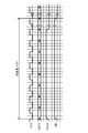
- FIG. 3 is a timing chart of each signal output from the interface device according to the first embodiment.
- FIG. 3 is a timing chart when the selector 7 selects a variable-length packet, that is, when a variable-length byte signal DATA is serially transmitted.
- the signal DATA which is variable length data such as a TLV packet, is transmitted in synchronization with the signal CLK.
- the signal PCLK may perform a predetermined operation in the vicinity of the head of the signal DATA, for example, becomes active in the first byte of the signal DATA.
- the selector 7 selects the TS packet, the signal DATA which is, for example, 188-byte fixed length data is transmitted in synchronization with the signal CLK.
- the back end processing unit 3 can implement a process for determining the leading position and valid period of the signal DATA, the signal PCLK and the signal DE may be omitted.
- the signal DATA may be transmitted in parallel.
- the selector 7 can select a TS packet having a fixed length, or a TLV packet or an IP packet having a variable length, and output it as a signal DATA. Therefore, in the interface device 2, it is possible to share a terminal for transmitting fixed-length packets and variable-length packets and a signal line for transmitting these packets.
- Non-Patent Document 2 discloses an example in which a total of four signals are used in addition to a data signal and a clock signal in order to transmit a TS packet. Therefore, this technique can be used to transmit the TS packet output from the receiving apparatus shown in FIG.
- TLV packet that is separated from the TS packet and output by the receiving apparatus in FIG. 7 of Patent Document 1 needs to be sent separately to the subsequent stage, but transmission of variable-length packets such as a TLV packet is clearly described in these documents. It has not been.
- TS packets and variable-length packets can be transmitted using the same terminal and signal line, so that a dedicated terminal and signal line for transmitting variable-length packets are not required. . That is, different types of data can be transmitted without increasing the number of terminals and the number of wirings.
- the cost of the interface device 2 can be reduced and the circuit scale can be reduced, and the back-end processing unit 3 does not need to increase the number of terminals.
- variable length packet acquisition unit 6 Next, a configuration example of the variable length packet acquisition unit 6 will be described.
- FIG. 4 is a block diagram illustrating a configuration example of the variable length packet acquisition unit according to the first embodiment.
- the variable length packet acquisition unit 6 includes a TLV packet acquisition unit 9, an IP packet generation unit 10, and a selector 11 as a second selector.
- variable-length packet acquisition unit 6 only needs to output a TLV packet
- the IP packet generation unit 10 and the selector 11 may be omitted.
- the TLV packet acquisition unit 9 can acquire the TLV packet from the output of the reception unit 4 based on the pointer / slot information included in the TMCC information. Further, the TLV packet acquisition unit 9 outputs a TLV packet corresponding to the TLV-ID selected by the remote controller or the like using the TLV-ID included in the TMCC information.
- the pointer / slot information is information indicating the start position of the first packet and the end position of the last packet included in each slot.
- the IP packet generator 10 generates an IP packet based on the header information of the TLV packet. Since the IP packet is transmitted in the TLV format, when the header information of the TLV packet indicates that the TLV packet is an IP packet, the IP packet is generated from the TLV packet. When generating an IP packet, tuning with a remote controller or the like, or protocols such as IGMP (Internet Group Management Protocol) and MLD (Multicast Listener Discovery) may be used.
- IGMP Internet Group Management Protocol
- MLD Multicast Listener Discovery
- IP packet generator 10 may be able to generate a UDP (User Datagram Protocol) packet.
- UDP User Datagram Protocol
- the selector 11 selects one of the outputs of the TLV packet acquisition unit 9 and the IP packet generation unit 10.
- the selector 11 may be switchable by a remote controller or the like.
- variable-length packet acquisition unit 6 By configuring the variable-length packet acquisition unit 6 in this way, it is possible to selectively output different types of packets such as TLV packets and IP packets.
- FIG. 5 is a block diagram illustrating a configuration example of the IP packet generation unit.
- the IP packet generation unit 10 includes, for example, an IP conversion unit 14 and a memory 15.
- the IP conversion unit 14 determines whether the header information of the input TLV packet indicates an IP packet. If the input packet is an IP packet in the TLV format, the IP conversion unit 14 removes the TLV header and converts it into an IP. Generate and output a packet.
- the IP unit 14 determines whether or not the header of the IP packet (IP / UDP header, hereinafter abbreviated as a header) is compressed. Is possible.
- the IP conversion unit 14 may output the TLV packet as it is without performing IP conversion.
- the memory 15 is a buffer and is configured to be capable of burst output of buffered packets. Note that the memory 15 may be provided before the IP unit 14.
- the IP packet generation unit 10 may be configured to be capable of burst output that outputs a buffered packet or stops output. Note that the IP packet generation unit 10 may be capable of continuously outputting packets.
- the IP packet generation unit 10 decompresses the header. Therefore, the transmission rate related to the output of the IP packet generation unit 10 when the header is compressed is It is preferably set to be higher than the case where it is not compressed.
- the transmission rate related to the output of the IP packet generation unit 10 is set to be higher than the transmission rate related to the input.
- FIG. 6 is a diagram for explaining data and transmission rates handled by the IP packet generation unit of FIG. 6A shows a case where the header is not compressed, and FIG. 6B shows a case where the header is compressed.
- FIG. 6 shows an example in which an IP packet in TLV format is input and output after being converted to IP.
- packets TLV1 and TLV2, which are TLV packets are input to the IP unit 14 at a transmission rate A1.
- the IP unit 14 the TLV headers of the packets TLV1 and TLV2 are removed, and packets IP1 and IP2, which are IP packets, are generated from each, and output at the transmission rate A2.
- Packets IP1 and IP2 are buffered in the memory 15, and burst output from the IP packet generator 10 at the transmission rate A3.
- packets TLV1 and TLV2 which are TLV packets are input to the IP unit 14 at the transmission rate B1.
- the TLV headers of the packets TLV1 and TLV2 are removed and the respective headers are expanded to generate IP packets IP1 and IP2, which are output at the transmission rate B2.
- Packets IP1 and IP2 are buffered in the memory 15, and burst output from the IP packet generator 10 at the transmission rate B3.
- the size of the packets IP1 and IP2 shown in FIG. 6B is larger than the size of the packets IP1 and IP2 shown in FIG. Also grows.
- the transmission rate B3 related to the output can be switched to be higher than the transmission rate B1 related to the input.
- the transmission rate B3 related to the output of the IP packet generation unit 10 when the header is compressed is higher than the transmission rate A3 related to the output of the IP packet generation unit 10 when the header is not compressed. It may be switchable.
- the transmission rates in the IP packet generation unit 10 are different so that the transmission rate A3 ⁇ transmission rate B3 or the transmission rate B1 ⁇ transmission rate B3.
- the transmission rate A3 may be matched with the transmission rate B3. In this case, it is not necessary to switch the transmission rate regardless of whether the header is compressed, and packets can be sent at a high transmission rate.
- FIG. 7 is another diagram for explaining the data and transmission rate handled by the IP packet generation unit of FIG. 7A shows a case where a TLV packet is output, and FIG. 7B shows a case where an IP packet is output. In FIG. 7B, it is assumed that the header is compressed.
- the packets TLV1 and TLV2 input to the IP conversion unit 14 are buffered in the memory 15, and the packet TLV1 is transmitted at the transmission rate A3.
- TLV2 is burst output.
- the IP conversion unit 14 removes the TLV headers of the packets TLV1 and TLV2 and expands the respective headers so that the packets IP1 and IP2 Are output at the transmission rate B2.
- Packets IP1 and IP2 are buffered in the memory 15, and burst output from the IP packet generator 10 at the transmission rate B3. At this time, it is sufficient that the transmission rate B1 ⁇ the transmission rate B3.
- FIG. 7A shows a case where a TLV packet is output, but the transmission rates A1 to A3 are set to be the same as the transmission rates B1 to B3 shown in FIG. 7B. Also good.
- GSE Generic Stream Encapsulated
- FIG. 8 is a block diagram of an interface device according to a modification of the first embodiment. In FIG. 8, differences from FIG. 2 will be mainly described.
- the reception unit 4 includes a first reception processing unit 4a and a second reception processing unit 4b.
- the reception processing unit 4a receives, for example, a first carrier wave related to terrestrial digital broadcasting, performs A / D conversion processing, demodulation processing, error correction processing, and the like, and converts it into a format necessary for processing in the TS packet acquisition unit 5. Output.
- the reception processing unit 4b receives, for example, a second carrier wave related to BS digital broadcasting, performs A / D conversion processing, demodulation processing, correction processing, and the like, and converts it into a format necessary for processing by the variable-length packet acquisition unit 6. Output.
- the receiving unit 4 receives a plurality of different carrier waves, performs the above-described processing on each carrier wave, and can output each processed signal to the TS packet acquisition unit 5 and the variable length packet acquisition unit 6, respectively. It may be configured.
- the selector 7 can selectively output variable-length packets such as TS packets or TLV packets, so that different types of packets can be transmitted through common terminals and signal lines.
- FIG. 9 is a block diagram of a receiving device including the interface device according to the second embodiment. In the present embodiment, differences from the first embodiment will be mainly described.
- the interface device 2 includes a reception unit 4, a TS packet acquisition unit 5, a variable length packet acquisition unit 6, a selector 7, and a packet adjustment unit 12.
- the packet adjustment unit 12 can adjust the size of a variable-length packet such as a TLV packet output from the variable-length packet acquisition unit 6 to be the same size as the TS packet. Therefore, when the size of the TS packet is, for example, 188 bytes, the packet adjustment unit 12 adjusts the size of the variable length packet to be 188 bytes. That is, the packet adjustment unit 12 can handle the variable length packet as a pseudo fixed length packet.
- the selector 7 selects and outputs one of the outputs of the TS packet acquisition unit 5, the variable length packet acquisition unit 6, and the packet adjustment unit 12.
- the packet adjustment unit 12 and the variable-length packet acquisition unit 6 may be integrated.
- the selector 7 selects and outputs either the TS packet acquisition unit 5 or the output of the circuit formed integrally therewith. Good.
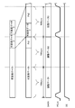
- FIG. 10 is a diagram for explaining a first example in which a fixed-length packet is formed from a variable-length packet.
- variable-length data 1 to variable-length data 4 that are variable-length packets having different sizes are adjusted to become adjustment data 1 to adjustment data 3 that are fixed-length data of, for example, 188 bytes. .
- variable length data 1 is longer than 188 bytes
- a part of the variable length data 1 is divided by 188 bytes to form the adjustment data 1.
- the adjustment data 2 is formed from the remaining data of the variable length data 1 and data obtained by dividing a part of the variable length data 2.
- the adjustment data 3 is formed from the remaining data of the variable length data 2, the variable length data 3, and the data obtained by dividing a part of the variable length data 4.
- the size of the variable length data is adjusted, and adjustment data having a fixed size is formed.
- FIG. 11 is a diagram for explaining a second example in which a fixed-length packet is formed from a variable-length packet.
- a TLV-ID included in a TMCC signal multiplexed and transmitted in advanced BS digital broadcasting will be described.
- variable length data 1 and variable length data 3 are selected by TLV-ID among variable length data 1 to variable length data 4 which are variable length packets.
- the unselected variable length data 2 and variable length data 4 are NULL.
- the process of making the non-selected variable length data 2 and variable length data 4 NULL may be performed by the variable length packet acquisition unit 6 or its preceding block, or may be performed by the packet adjustment unit 12. .
- the adjustment data 2 is formed from the remaining data of the variable length data 1 and the data obtained by dividing a part of the NULL data.
- the adjustment data 3 is formed from the remaining data of the NULL data, the variable length data 3, and the data obtained by dividing a part of the NULL data.
- the non-selected variable-length data may be replaced with arbitrary data such as 0xFF, for example, as predetermined data instead of simple NULL data.
- the NULL data may have a header part that the variable-length data has in common, and the NULL data may have a format in which the size of the NULL data is known.
- adjustment data is formed from an IP packet as a variable-length packet.
- non-selected variable-length data is replaced with NULL data, but non-selected variable-length data may be removed. That is, in the state immediately before the adjustment shown in FIG. 11, the variable length data 1 may be followed by the variable length data 3 instead of the NULL data.
- FIG. 12 is a timing chart when the fixed-length packet shown in FIGS. 10 and 11 is transmitted.
- variable-length packets are sent in units of 188 bytes, for example, variable-length packets can be sent in the same format as TS packets that are fixed-length data.
- variable-length packets can be handled as fixed-length data.
- the signal PCLK and the signal DE may be omitted. Further, the signal PCLK may become active every the same size (for example, 188 bytes) as the TS packet. Alternatively, the signal PCLK may become active at the head position of the variable length data before the size is adjusted.
- FIG. 13 is a third example in which a fixed-length packet is formed from variable-length packets and a timing chart in the case of sending it. Note that the signal CLK is omitted.
- FIG. 13 shows an example in which the size of the variable-length packet is adjusted to be an integral multiple of the fixed-length packet.
- variable length data 1 which is a variable length packet is divided into fixed length data 1 of 188 bytes and data of less than 188 bytes. At this time, the data of less than 188 bytes is dummy data. Data Pd1 is added.
- the adjustment data 1 is formed from the data of the first 188 bytes of the variable length data 1
- the adjustment data 2 is formed by adding the data Pd1 to the remaining variable length data 1 until the size becomes 188 bytes.
- variable length data 2 is less than 188 bytes
- data Pd2 which is dummy data is added to the variable length data 2 until the size becomes 188 bytes. That is, the adjustment data 3 is formed from the variable length data 2 and the data Pd2.
- the signal PCLK that becomes active at the head position of the variable length data 1 to variable length data 3 that is the data before the size is adjusted is used.
- the transmission rate on the output side is set higher than the transmission rate on the input side to prevent overflow. May be.
- the dummy data is added to the end of the variable length data, but may be added to the top of the variable length data. That is, it is only necessary that the size of the variable-length data becomes the same as the size of the TS packet by adding dummy data.
- the packet adjustment unit 12 adjusts the size of the variable length packet to form fixed length data having the same size as the TS packet.
- the variable length packet input to the packet adjustment unit 12 may include predetermined dummy data.
- the signal PCLK becomes active at the head position of the variable length data 1 to variable length data 3. That is, the signal PCLK is a signal indicating the head position of the data, but may be active at the head position of the adjustment data corresponding to the head position of the variable length data.
- the back-end processing unit 3 can receive the variable-length packet as fixed-length data, and determines the actual start position of the received data (that is, the start position of the variable-length packet) based on the signal PCLK. Judgment can be made.
- variable-length packet As described above, by changing the variable-length packet to a pseudo-fixed-length packet, it is possible to reduce changes in processing content, transmission protocol, and the like in the back-end processing unit 3.
- variable length packet is sent as it is.
- the back-end processing unit 3 needs to specify the boundary between the variable-length packets by calculating the head position and size of the packet from the packet header information. At this time, if the header information cannot be analyzed for some reason (such as garbled data), the back-end processing unit 3 may not be able to perform normal processing.
- the interface device 2 should transmit a signal DATA as shown in FIG. Good.
- FIG. 14 is a timing chart when a plurality of variable-length packets are transmitted with a variable length. Note that the signal CLK is omitted.
- a signal PCLK that becomes active at each head position of variable length data 1 to variable length data 3 which is a variable length packet is sent together with variable length data 1 to variable length data 3.
- the back-end processing unit 3 can accurately recognize the head positions of the variable length data 1 to the variable length data 3 based on the signal PCLK. Therefore, in the back-end processing unit 3, for example, software processing by a CPU (Central Processing Unit) may be implemented so as to specify variable length data based on the signal PCLK.
- a CPU Central Processing Unit
- the interface device can transmit a plurality of different types of signals without increasing the number of terminals and the number of wires, and thus is useful for reducing the circuit scale and cost of the receiving device.
Abstract
An interface device (2) for sending out a data signal (DATA) in synchronization with a clock signal (CLK) comprises: a reception unit (4) that subjects an input carrier to a demodulation process and an error correction process and that outputs a signal as subjected to these processes; a TS packet acquisition unit (5) that acquires a TS packet included in the output of the reception unit; a variable-length packet acquisition unit (6) that acquires a variable-length packet included in the output of the reception unit; and a first selector (7) that selects either the TS packet or the variable-length packet and that outputs the selected packet as the data signal.
Description
本開示は、インタフェース装置に関し、特に、テレビ等に用いられる受信装置のフロントエンドからバックエンドにデータを伝送する技術に関する。
The present disclosure relates to an interface device, and more particularly, to a technique for transmitting data from a front end to a back end of a receiving device used for a television or the like.
従来、放送などに用いられるトランスポートストリーム(TS:Transport Stream)とともに、通信などに用いられる可変長パケットを伝送可能とする技術が知られている。例えば、高度BSデジタル放送では、TSパケットとTLV(Type Length Value)パケットとが伝送可能となっている(例えば、非特許文献1参照)。この技術によると、IP(Internet Protocol)パケットはTLV形式で伝送される。
2. Description of the Related Art Conventionally, a technique that enables transmission of variable-length packets used for communication and the like along with a transport stream (TS) used for broadcasting or the like is known. For example, in advanced BS digital broadcasting, TS packets and TLV (Type (Length Value) packets can be transmitted (for example, see Non-Patent Document 1). According to this technology, an IP (Internet Protocol) packet is transmitted in the TLV format.
TSパケットとTLVパケット等の可変長パケットとを同時に伝送する装置として、TSパケットと可変長パケットとを多重化して送出する送信装置と、多重化信号を受信してTSパケットと可変長パケットとに分離する受信装置とが開示されている(例えば、特許文献1参照)。
As a device that simultaneously transmits TS packets and variable-length packets such as TLV packets, a transmission device that multiplexes and transmits TS packets and variable-length packets, and receives multiplexed signals into TS packets and variable-length packets A receiving device to be separated is disclosed (for example, see Patent Document 1).
このような受信装置では、フロントエンドによってTSパケットと可変長パケットとが分離された後、これらパケットに対してバックエンドによって復号化等が実行されるのが一般的である。
In such a receiving apparatus, after a TS packet and a variable-length packet are separated by a front end, decoding and the like are generally performed on these packets by a back end.
特許文献1の図7に示すデータ信号としてのTSパケットは、例えば非特許文献2の特にP12,P13に示すように、クロック信号の他に2種類の信号を用いて伝送可能である。
The TS packet as the data signal shown in FIG. 7 of Patent Document 1 can be transmitted using two types of signals in addition to the clock signal, as shown in P12 and P13 of Non-Patent Document 2, for example.
特許文献1の図7の受信装置では、TSパケットの他に、TLVパケットを伝送する必要がある。TLVパケットをどのように伝送するかについては、特許文献1および他の文献には開示されていない。
In the receiving apparatus of FIG. 7 of Patent Document 1, it is necessary to transmit a TLV packet in addition to a TS packet. How to transmit a TLV packet is not disclosed in Patent Document 1 and other documents.
そこで、フロントエンドからバックエンドに可変長パケットを伝送するために、例えば、特許文献1の図7の受信装置において、可変長パケット伝送用の端子や配線を設けることが考えられる。
Therefore, in order to transmit a variable length packet from the front end to the back end, for example, it is conceivable to provide a terminal or wiring for variable length packet transmission in the receiving apparatus of FIG.
しかしながら、可変長パケットを伝送するための専用の端子や配線を設けると、端子数や配線数が増加してしまい、結果として、受信装置のコストの増加や、回路規模の増大を招くおそれがある。また、配線数の増加により、バックエンド側の端子数にも変更が生じうる。
However, if a dedicated terminal or wiring for transmitting a variable-length packet is provided, the number of terminals and the number of wirings increase, and as a result, the cost of the receiving device may increase and the circuit scale may increase. . Further, the number of terminals on the back end side can be changed due to the increase in the number of wirings.
かかる点に鑑みて、本開示は、端子数や配線数の増加を招くことなく、TSパケットおよび可変長パケットの伝送が可能なインタフェース装置を提供することを課題とする。
In view of the above, an object of the present disclosure is to provide an interface device capable of transmitting TS packets and variable-length packets without causing an increase in the number of terminals or the number of wires.
上記課題を解決するため本開示によって次のような解決手段を講じた。すなわち、クロック信号に同期してデータ信号を送出するインタフェース装置は、入力された搬送波に対して復調処理および誤り訂正処理を行い、これら処理後の信号を出力する受信部と、前記受信部の出力に含まれるTSパケットを取得するTSパケット取得部と、前記受信部の出力に含まれる可変長パケットを取得する可変長パケット取得部と、前記TSパケットおよび前記可変長パケットのいずれかを選択し、当該選択したパケットを前記データ信号として出力する第1のセレクタとを備えている。
In order to solve the above-mentioned problems, the present disclosure has taken the following solutions. That is, an interface device that transmits a data signal in synchronization with a clock signal performs demodulation processing and error correction processing on an input carrier wave, and outputs a signal after the processing, and an output of the receiving portion A TS packet acquisition unit that acquires TS packets included in, a variable length packet acquisition unit that acquires a variable length packet included in the output of the reception unit, and select either the TS packet or the variable length packet, And a first selector that outputs the selected packet as the data signal.
これによると、インタフェース装置が受信した、例えば、地上デジタル放送、高度BSデジタル放送、および通信などの信号を含む搬送波に対して、受信部によって復調処理や誤り訂正処理がなされる。そして、受信部の出力から、TSパケット取得部によってTSパケットが、可変長パケット取得部によって可変長パケットがそれぞれ抽出される。その後、第1のセレクタによって、TSパケットあるいは可変長パケットがデータ信号として選択的に出力され、データ信号が、クロック信号に同期してインタフェース装置から送出される。
According to this, demodulation processing and error correction processing are performed by the receiving unit on a carrier wave including signals such as terrestrial digital broadcasting, advanced BS digital broadcasting, and communication received by the interface device. Then, TS packets are extracted from the output of the reception unit by the TS packet acquisition unit, and variable-length packets are extracted by the variable-length packet acquisition unit. Thereafter, the first selector selectively outputs a TS packet or a variable-length packet as a data signal, and the data signal is transmitted from the interface device in synchronization with the clock signal.
これにより、TSパケットおよび可変長パケットを出力するための端子および配線を共通化することができる。換言すると、可変長パケットを出力するための、専用の端子および配線を別途設ける必要がないため、端子数および配線数の増加を招くことなく、これらパケットの伝送が可能となる。その結果、当該インタフェース装置を備える受信装置の低コスト化および省面積化を図ることができる。
This makes it possible to share terminals and wiring for outputting TS packets and variable-length packets. In other words, it is not necessary to separately provide dedicated terminals and wires for outputting variable-length packets, so that these packets can be transmitted without increasing the number of terminals and wires. As a result, it is possible to reduce the cost and area of the receiving device including the interface device.
また、当該インタフェース装置から伝送された信号を受けるバックエンド側の装置において、端子数やプロトコル等の仕様変更が少なくても済む。
Also, in the back-end side device that receives the signal transmitted from the interface device, the specification change such as the number of terminals and the protocol can be reduced.
あるいは、受信装置は、上記インタフェース装置をフロントエンド側の処理装置として備えていてもよい。
Alternatively, the receiving device may include the interface device as a front-end processing device.
本開示によれば、端子数や配線数の増加を招くことなく、TSパケットおよび可変長パケットの伝送が可能なインタフェース装置を提供することができる。
According to the present disclosure, it is possible to provide an interface device that can transmit TS packets and variable-length packets without increasing the number of terminals or the number of wires.
<第1の実施形態>
図1は、第1の実施形態に係るインタフェース装置を備えた受信装置のブロック図である。この受信装置1は、例えば、デジタルテレビ等に搭載され、地上デジタル放送や高度BSデジタル放送、およびケーブルテレビ等の各種放送サービス、ならびに、IPパケット等を用いた通信サービスに係る信号を受信可能である。受信装置1は、フロントエンド処理部としてのインタフェース装置2と、バックエンド処理部3とを有する。 <First Embodiment>
FIG. 1 is a block diagram of a receiving device including an interface device according to the first embodiment. Thereceiving device 1 is mounted on, for example, a digital television, and can receive signals related to various broadcasting services such as terrestrial digital broadcasting, advanced BS digital broadcasting, and cable television, and communication services using IP packets and the like. is there. The receiving device 1 includes an interface device 2 as a front end processing unit and a back end processing unit 3.
図1は、第1の実施形態に係るインタフェース装置を備えた受信装置のブロック図である。この受信装置1は、例えば、デジタルテレビ等に搭載され、地上デジタル放送や高度BSデジタル放送、およびケーブルテレビ等の各種放送サービス、ならびに、IPパケット等を用いた通信サービスに係る信号を受信可能である。受信装置1は、フロントエンド処理部としてのインタフェース装置2と、バックエンド処理部3とを有する。 <First Embodiment>
FIG. 1 is a block diagram of a receiving device including an interface device according to the first embodiment. The
インタフェース装置2は、アンテナから入力される、例えばI/Q(In-phase/Quadrature-phase)信号やIF(Intermediate Frequency)信号等の、少なくとも1つの搬送波を受信し、搬送波からTSパケットと可変長パケットとを抽出し、これらパケットをデータ信号DATAとしてクロック信号CLKに同期してバックエンド処理部3に送出する。搬送波は、例えばテレビ放送(BS放送や地上デジタル放送等)や通信に係る信号を含む。
The interface device 2 receives at least one carrier wave such as an I / Q (In-phase / Quadrature-phase) signal or an IF (Intermediate Frequency) signal input from an antenna, and has a variable length with a TS packet from the carrier wave. Packets are extracted, and these packets are sent as data signals DATA to the back-end processing unit 3 in synchronization with the clock signal CLK. The carrier wave includes, for example, a signal related to television broadcasting (BS broadcasting, digital terrestrial broadcasting, etc.) and communication.
また、インタフェース装置2は、信号DATAの先頭位置を示すパケットクロック信号PCLKおよび信号DATAの有効期間を示すデータイネーブル信号DEの出力が可能である。
Further, the interface device 2 can output the packet clock signal PCLK indicating the head position of the signal DATA and the data enable signal DE indicating the valid period of the signal DATA.
図2は、第1の実施形態に係るインタフェース装置のブロック図である。インタフェース装置2は、受信部4と、TSパケット取得部5と、可変長パケット取得部6と、第1のセレクタとしてのセレクタ7とを有する。
FIG. 2 is a block diagram of the interface device according to the first embodiment. The interface device 2 includes a reception unit 4, a TS packet acquisition unit 5, a variable length packet acquisition unit 6, and a selector 7 as a first selector.
受信部4は、入力された搬送波に対して、例えば、A/D(Analogue-to-Digital)変換処理、8PSK(Phase ShiftKeying)や16APSK(Amplitude and Phase ShiftKeying)といった復調処理、および、LDPC(Low DensityParity Check)符号やBCH(Bose-Chaudhuri-Hocquenghem)符号等を用いた誤り訂正処理を行う。
The receiving unit 4 performs, for example, A / D (Analogue-to-Digital) conversion processing, demodulation processing such as 8PSK (Phase Shift Keying) and 16 APSK (Amplitude Shift and Phase Shift Keying), and LDPC (Low Error correction processing using a Density Parity Check) code, a BCH (Bose-Chaudhuri-Hocquenghem) code, or the like is performed.
なお、受信部4は上記以外の処理を行ってもよく、TSパケット取得部5および可変長パケット取得部6に必要な信号を出力可能であればよい。
The receiving unit 4 may perform processes other than those described above as long as it can output necessary signals to the TS packet acquiring unit 5 and the variable length packet acquiring unit 6.
また、受信部4には、チューナが含まれていてもよく、リモコン等の操作によってチューナで選局された放送に係る信号が入力されてもよい。
Further, the receiving unit 4 may include a tuner, and a signal related to broadcasting selected by the tuner by an operation of a remote controller or the like may be input.
TSパケット取得部5は、搬送波に含まれるTMCC(Transmission and Multiplexing Configuration and Control)情報に基づいて、受信部4の出力から固定長であるTSパケットを取得して出力する。例えば、TSパケット取得部5は、指示されたTS-ID(TS-Identifier)に応じたTSパケットを抽出可能である。
The TS packet acquisition unit 5 acquires and outputs a TS packet having a fixed length from the output of the reception unit 4 based on TMCC (Transmission and Multiplexing Configuration and control) information included in the carrier wave. For example, the TS packet acquisition unit 5 can extract a TS packet corresponding to the instructed TS-ID (TS-Identifier).
可変長パケット取得部6は、TMCC情報に基づいて、受信部4の出力から、可変長であるTLVパケットやIPパケット等の可変長パケットを取得して出力する。なお、可変長パケット取得部6は、TSパケット取得部5の後段側に接続されていてもよい。また、例えば、可変長パケット取得部6は、リモコン等により指示されたTLV-ID(TLV-Identifier)に応じたTLVパケットを抽出可能であってもよい。
The variable length packet acquisition unit 6 acquires and outputs a variable length packet such as a TLV packet or an IP packet having a variable length from the output of the reception unit 4 based on the TMCC information. The variable-length packet acquisition unit 6 may be connected to the subsequent stage side of the TS packet acquisition unit 5. Further, for example, the variable length packet acquisition unit 6 may be able to extract a TLV packet corresponding to a TLV-ID (TLV-Identifier) instructed by a remote controller or the like.
つまり、TSパケット取得部5がTSパケットを、可変長パケット取得部6が可変長パケットを、受信部4の出力から取得可能であればよい。
That is, it is only necessary that the TS packet acquisition unit 5 can acquire the TS packet and the variable length packet acquisition unit 6 can acquire the variable length packet from the output of the reception unit 4.
セレクタ7は、TSパケット取得部5の出力および可変長パケット取得部6の出力のいずれか一方を選択的に出力する。例えば、セレクタ7は、リモコンの選局に応じて、TSパケットあるいは可変長パケットの選択を切り替えてもよく、バックエンド処理部3からの指示に応じて切り替えてもよい。セレクタ7は、選択したパケットを信号DATAとして出力する。
The selector 7 selectively outputs one of the output of the TS packet acquisition unit 5 and the output of the variable length packet acquisition unit 6. For example, the selector 7 may switch the selection of the TS packet or the variable-length packet according to the tuning of the remote controller, or may switch according to the instruction from the back end processing unit 3. The selector 7 outputs the selected packet as a signal DATA.
なお、セレクタ7は、信号CLK、信号PCLK、および信号DEを生成可能な回路を含んでいてもよく、当該回路はインタフェース装置2の内部に設けられていればよい。
Note that the selector 7 may include a circuit that can generate the signal CLK, the signal PCLK, and the signal DE, and the circuit only needs to be provided inside the interface device 2.
また、セレクタ7は、任意のタイミングでTSパケットあるいは可変長パケットの選択を切り替えてもよい。例えば、セレクタ7の入力が時分割で多重化されている場合には、セレクタ7の切り替えが、その時分割多重化データに応じて行われてもよい。
Further, the selector 7 may switch the selection of the TS packet or the variable length packet at an arbitrary timing. For example, when the input of the selector 7 is multiplexed in a time division manner, the selector 7 may be switched in accordance with the time division multiplexing data.
図3は、第1の実施形態に係るインタフェース装置から出力される各信号のタイミングチャートである。なお、図3は、セレクタ7が可変長パケットを選択している場合、つまり可変長バイトの信号DATAがシリアル伝送される場合のタイミングチャートである。
FIG. 3 is a timing chart of each signal output from the interface device according to the first embodiment. FIG. 3 is a timing chart when the selector 7 selects a variable-length packet, that is, when a variable-length byte signal DATA is serially transmitted.
図3に示すように、TLVパケット等の可変長データである信号DATAは、信号CLKに同期して送出される。なお、信号PCLKは、信号DATAの例えば先頭1バイトにおいてアクティブになるなど、信号DATAの先頭付近であらかじめ定められた動作をしてもよい。
As shown in FIG. 3, the signal DATA, which is variable length data such as a TLV packet, is transmitted in synchronization with the signal CLK. Note that the signal PCLK may perform a predetermined operation in the vicinity of the head of the signal DATA, for example, becomes active in the first byte of the signal DATA.
また、セレクタ7がTSパケットを選択している場合には、例えば188バイトの固定長データである信号DATAが信号CLKに同期して送出される。
Further, when the selector 7 selects the TS packet, the signal DATA which is, for example, 188-byte fixed length data is transmitted in synchronization with the signal CLK.
また、バックエンド処理部3において、信号DATAの先頭位置および有効期間を判定する処理を実装可能である場合には、信号PCLKおよび信号DEを省略してもよい。
Further, when the back end processing unit 3 can implement a process for determining the leading position and valid period of the signal DATA, the signal PCLK and the signal DE may be omitted.
また、信号DATAはパラレル伝送されてもよい。
Further, the signal DATA may be transmitted in parallel.
以上、本実施形態によると、セレクタ7は、固定長であるTSパケット、あるいは可変長であるTLVパケットやIPパケットを選択して、信号DATAとして出力可能である。したがって、インタフェース装置2において、固定長パケットと可変長パケットとを送出するための端子、およびこれらのパケットを伝送するための信号線を共有化することができる。
As described above, according to the present embodiment, the selector 7 can select a TS packet having a fixed length, or a TLV packet or an IP packet having a variable length, and output it as a signal DATA. Therefore, in the interface device 2, it is possible to share a terminal for transmitting fixed-length packets and variable-length packets and a signal line for transmitting these packets.
ここで、非特許文献2には、TSパケットを伝送するために、データ信号およびクロック信号の他に2種類、計4本の信号を用いる例が開示されている。したがって、特許文献1の図7に示す受信装置から出力されるTSパケットを後段に伝送するために、その技術を用いることができる。
Here, Non-Patent Document 2 discloses an example in which a total of four signals are used in addition to a data signal and a clock signal in order to transmit a TS packet. Therefore, this technique can be used to transmit the TS packet output from the receiving apparatus shown in FIG.
ところが、特許文献1の図7の受信装置でTSパケットと分離されて出力されるTLVパケットも別途後段に送出する必要があるが、TLVパケット等の可変長パケットの伝送についてはこれら文献には明記されていない。
However, the TLV packet that is separated from the TS packet and output by the receiving apparatus in FIG. 7 of Patent Document 1 needs to be sent separately to the subsequent stage, but transmission of variable-length packets such as a TLV packet is clearly described in these documents. It has not been.
そこで、TLVパケットを送出するための専用の端子および配線を設けることが考えられるが、そうすると、装置のコストや回路規模が増大するおそれがある。また、端子数や配線数の増加は、後段側の装置の大幅な仕様変更につながる可能性がある。
Therefore, it is conceivable to provide a dedicated terminal and wiring for transmitting the TLV packet. However, there is a risk that the cost of the apparatus and the circuit scale may increase. In addition, an increase in the number of terminals and the number of wirings may lead to a drastic change in specifications of the device on the rear stage side.
これに対して、本実施形態では、TSパケットと可変長パケットとを同じ端子および信号線を用いて伝送可能であるため、可変長パケットを伝送するための専用の端子および信号線が不要である。つまり、端子数および配線数の増加を招くことなく、異なる種類のデータの伝送が可能である。
In contrast, in the present embodiment, TS packets and variable-length packets can be transmitted using the same terminal and signal line, so that a dedicated terminal and signal line for transmitting variable-length packets are not required. . That is, different types of data can be transmitted without increasing the number of terminals and the number of wirings.
これにより、インタフェース装置2の低コスト化や回路規模の縮小化を図ることができるとともに、バックエンド処理部3においても端子数を増やす必要がないため、その構成を大きく変更する必要がない。
As a result, the cost of the interface device 2 can be reduced and the circuit scale can be reduced, and the back-end processing unit 3 does not need to increase the number of terminals.
次に、可変長パケット取得部6の構成例について説明する。
Next, a configuration example of the variable length packet acquisition unit 6 will be described.
図4は、第1の実施形態に係る可変長パケット取得部の構成例を示すブロック図である。
FIG. 4 is a block diagram illustrating a configuration example of the variable length packet acquisition unit according to the first embodiment.
可変長パケット取得部6は、TLVパケット取得部9と、IPパケット生成部10と、第2のセレクタとしてのセレクタ11とを有する。
The variable length packet acquisition unit 6 includes a TLV packet acquisition unit 9, an IP packet generation unit 10, and a selector 11 as a second selector.
なお、可変長パケット取得部6において、TLVパケットのみを出力すればよい場合は、IPパケット生成部10およびセレクタ11を省略してもよい。
If the variable-length packet acquisition unit 6 only needs to output a TLV packet, the IP packet generation unit 10 and the selector 11 may be omitted.
TLVパケット取得部9は、受信部4の出力から、TMCC情報に含まれるポインタ/スロット情報に基づいてTLVパケットを取得可能である。また、TLVパケット取得部9は、TMCC情報に含まれるTLV-IDを用いて、リモコン等で選局されたTLV-IDに対応するTLVパケットを出力する。ポインタ/スロット情報は、スロット毎に包含される、最初のパケットの先頭位置、および最後のパケットの末尾の位置を示す情報である。
The TLV packet acquisition unit 9 can acquire the TLV packet from the output of the reception unit 4 based on the pointer / slot information included in the TMCC information. Further, the TLV packet acquisition unit 9 outputs a TLV packet corresponding to the TLV-ID selected by the remote controller or the like using the TLV-ID included in the TMCC information. The pointer / slot information is information indicating the start position of the first packet and the end position of the last packet included in each slot.
IPパケット生成部10は、TLVパケットのヘッダ情報に基づいてIPパケットを生成する。IPパケットはTLV形式で伝送されているため、TLVパケットのヘッダ情報が、そのTLVパケットがIPパケットであることを示す場合に、TLVパケットからIPパケットが生成される。IPパケットの生成に際して、リモコン等による選局や、IGMP(Internet Group Management Protocol)およびMLD(Multicast ListenerDiscovery)等のプロトコルを用いてもよい。
The IP packet generator 10 generates an IP packet based on the header information of the TLV packet. Since the IP packet is transmitted in the TLV format, when the header information of the TLV packet indicates that the TLV packet is an IP packet, the IP packet is generated from the TLV packet. When generating an IP packet, tuning with a remote controller or the like, or protocols such as IGMP (Internet Group Management Protocol) and MLD (Multicast Listener Discovery) may be used.
なお、IPパケット生成部10は、UDP(User DatagramProtocol)パケットを生成可能であってもよい。
Note that the IP packet generator 10 may be able to generate a UDP (User Datagram Protocol) packet.
セレクタ11は、TLVパケット取得部9およびIPパケット生成部10の出力のうちいずれかを選択する。なお、セレクタ11は、リモコン等によって切り替え可能であってもよい。
The selector 11 selects one of the outputs of the TLV packet acquisition unit 9 and the IP packet generation unit 10. The selector 11 may be switchable by a remote controller or the like.
このように可変長パケット取得部6を構成することにより、TLVパケットとIPパケットといった異なる種類のパケットの選択的な出力が可能となる。
By configuring the variable-length packet acquisition unit 6 in this way, it is possible to selectively output different types of packets such as TLV packets and IP packets.
図5は、IPパケット生成部の構成例を示すブロック図である。図5に示すように、IPパケット生成部10は、例えば、IP化部14と、メモリ15とを有する。
FIG. 5 is a block diagram illustrating a configuration example of the IP packet generation unit. As illustrated in FIG. 5, the IP packet generation unit 10 includes, for example, an IP conversion unit 14 and a memory 15.
IP化部14は、入力されるTLVパケットのヘッダ情報が、IPパケットを示すかどうかを判定し、入力されたパケットがTLV形式のIPパケットであれば、TLVヘッダを除去してIP化し、IPパケットを生成して出力する。
The IP conversion unit 14 determines whether the header information of the input TLV packet indicates an IP packet. If the input packet is an IP packet in the TLV format, the IP conversion unit 14 removes the TLV header and converts it into an IP. Generate and output a packet.
また、IP化部14は、IPパケットのヘッダ(IP/UDPヘッダ、以下、ヘッダと略記する)が圧縮されているかどうかを判定し、圧縮されている場合には、そのヘッダを伸長して出力可能である。
Further, the IP unit 14 determines whether or not the header of the IP packet (IP / UDP header, hereinafter abbreviated as a header) is compressed. Is possible.
なお、IP化部14は、入力されたTLVパケットが、TLV形式のIPパケットではない場合、IP化は行わず、TLVパケットをそのまま出力してもよい。
Note that when the input TLV packet is not a TLV format IP packet, the IP conversion unit 14 may output the TLV packet as it is without performing IP conversion.
メモリ15は、バッファであり、バッファしたパケットのバースト出力が可能に構成されている。なお、メモリ15を、IP化部14の前段に設けてもよい。
The memory 15 is a buffer and is configured to be capable of burst output of buffered packets. Note that the memory 15 may be provided before the IP unit 14.
このように、IPパケット生成部10は、バッファされたパケットを出力したり、出力の停止をしたりするバースト出力が可能な構成であってもよい。なお、IPパケット生成部10は、パケットを連続的に出力可能であってもよい。
As described above, the IP packet generation unit 10 may be configured to be capable of burst output that outputs a buffered packet or stops output. Note that the IP packet generation unit 10 may be capable of continuously outputting packets.
ここで、IPパケットのヘッダが圧縮されている場合、IPパケット生成部10においてヘッダが伸長されるため、ヘッダが圧縮されている場合におけるIPパケット生成部10の出力に係る伝送レートは、ヘッダが圧縮されていない場合よりも高くなるように設定されていることが好ましい。
Here, when the header of the IP packet is compressed, the IP packet generation unit 10 decompresses the header. Therefore, the transmission rate related to the output of the IP packet generation unit 10 when the header is compressed is It is preferably set to be higher than the case where it is not compressed.
あるいは、IPパケットのヘッダが圧縮されている場合、IPパケット生成部10の出力に係る伝送レートは、入力に係る伝送レートよりも高くなるように設定されていることが好ましい。
Alternatively, when the IP packet header is compressed, it is preferable that the transmission rate related to the output of the IP packet generation unit 10 is set to be higher than the transmission rate related to the input.
これらの点について、図6および図7を用いて説明する。
These points will be described with reference to FIG. 6 and FIG.
図6は、図5のIPパケット生成部で扱われるデータと伝送レートを説明するための図である。図6(A)はヘッダが圧縮されていない場合、図6(B)はヘッダが圧縮されている場合を示す。なお、図6では、TLV形式のIPパケットが入力され、IP化されてから出力される例を示す。
FIG. 6 is a diagram for explaining data and transmission rates handled by the IP packet generation unit of FIG. 6A shows a case where the header is not compressed, and FIG. 6B shows a case where the header is compressed. FIG. 6 shows an example in which an IP packet in TLV format is input and output after being converted to IP.
図6(A)において、伝送レートA1で、TLVパケットであるパケットTLV1,TLV2がIP化部14に入力される。IP化部14では、パケットTLV1,TLV2のTLVヘッダが除去され、それぞれからIPパケットであるパケットIP1,IP2が生成され、伝送レートA2で出力される。
6A, packets TLV1 and TLV2, which are TLV packets, are input to the IP unit 14 at a transmission rate A1. In the IP unit 14, the TLV headers of the packets TLV1 and TLV2 are removed, and packets IP1 and IP2, which are IP packets, are generated from each, and output at the transmission rate A2.
パケットIP1,IP2はメモリ15でバッファされ、伝送レートA3でIPパケット生成部10からバースト出力される。
Packets IP1 and IP2 are buffered in the memory 15, and burst output from the IP packet generator 10 at the transmission rate A3.
なお、図6(A)に示す伝送レートA1~A3は任意である。
Note that the transmission rates A1 to A3 shown in FIG. 6A are arbitrary.
一方、図6(B)において、伝送レートB1で、TLVパケットであるパケットTLV1,TLV2がIP化部14に入力される。IP化部14では、パケットTLV1,TLV2のTLVヘッダが除去され、かつそれぞれのヘッダが伸長され、IPパケットであるパケットIP1,IP2が生成され、伝送レートB2で出力される。
On the other hand, in FIG. 6B, packets TLV1 and TLV2 which are TLV packets are input to the IP unit 14 at the transmission rate B1. In the IP unit 14, the TLV headers of the packets TLV1 and TLV2 are removed and the respective headers are expanded to generate IP packets IP1 and IP2, which are output at the transmission rate B2.
パケットIP1,IP2はメモリ15でバッファされ、伝送レートB3でIPパケット生成部10からバースト出力される。
Packets IP1 and IP2 are buffered in the memory 15, and burst output from the IP packet generator 10 at the transmission rate B3.
このように、ヘッダが圧縮されている場合、その伸長を行う必要があるため、図6(B)に示すパケットIP1,IP2のサイズは、図6(A)に示すパケットIP1,IP2のサイズよりも大きくなる。
As described above, when the header is compressed, it is necessary to expand the header. Therefore, the size of the packets IP1 and IP2 shown in FIG. 6B is larger than the size of the packets IP1 and IP2 shown in FIG. Also grows.
そこで、本実施形態に係るIPパケット生成部10では、ヘッダが圧縮されている場合において、その出力に係る伝送レートB3を、その入力に係る伝送レートB1よりも高くなるように切り替え可能としている。
Therefore, in the IP packet generation unit 10 according to the present embodiment, when the header is compressed, the transmission rate B3 related to the output can be switched to be higher than the transmission rate B1 related to the input.
あるいは、ヘッダが圧縮されている場合におけるIPパケット生成部10の出力に係る伝送レートB3を、ヘッダが圧縮されていない場合におけるIPパケット生成部10の出力に係る伝送レートA3よりも高くなるように切り替え可能としてもよい。
Alternatively, the transmission rate B3 related to the output of the IP packet generation unit 10 when the header is compressed is higher than the transmission rate A3 related to the output of the IP packet generation unit 10 when the header is not compressed. It may be switchable.
つまり、伝送レートA3<伝送レートB3、あるいは、伝送レートB1<伝送レートB3という関係となるようにIPパケット生成部10における伝送レートが異なっていればよい。
That is, it is only necessary that the transmission rates in the IP packet generation unit 10 are different so that the transmission rate A3 <transmission rate B3 or the transmission rate B1 <transmission rate B3.
なお、伝送レートB2と伝送レートB3とについて、伝送レートとして高い周波数のクロックを用いることで、一定のクロックを用いたバースト出力が可能となる。
Note that, for the transmission rate B2 and the transmission rate B3, burst output using a constant clock is possible by using a high-frequency clock as the transmission rate.
また、伝送レートA3を伝送レートB3に合わせてもよい。この場合、ヘッダが圧縮されているかどうかにかかわらず、伝送レートの切り替えが不要であるとともに、高い伝送レートでのパケットの送出が可能となる。
Further, the transmission rate A3 may be matched with the transmission rate B3. In this case, it is not necessary to switch the transmission rate regardless of whether the header is compressed, and packets can be sent at a high transmission rate.
図7は、図5のIPパケット生成部で扱われるデータと伝送レートを説明するための別の図である。図7(A)はTLVパケットが出力される場合、図7(B)はIPパケットが出力される場合を示す。なお、図7(B)では、ヘッダが圧縮されているものとする。
FIG. 7 is another diagram for explaining the data and transmission rate handled by the IP packet generation unit of FIG. 7A shows a case where a TLV packet is output, and FIG. 7B shows a case where an IP packet is output. In FIG. 7B, it is assumed that the header is compressed.
図7(A)に示すように、IPパケット生成部10によってTLVパケットがIP化されない場合、IP化部14に入力されたパケットTLV1,TLV2はメモリ15でバッファされ、伝送レートA3でパケットTLV1,TLV2がバースト出力される。
As shown in FIG. 7A, when the TLV packet is not converted to IP by the IP packet generation unit 10, the packets TLV1 and TLV2 input to the IP conversion unit 14 are buffered in the memory 15, and the packet TLV1 is transmitted at the transmission rate A3. TLV2 is burst output.
一方、図7(B)に示すように、TLVパケットがIP化される場合、IP化部14において、パケットTLV1,TLV2のTLVヘッダが除去され、かつそれぞれのヘッダが伸長され、パケットIP1,IP2が伝送レートB2で出力される。
On the other hand, as shown in FIG. 7B, when the TLV packet is converted to the IP, the IP conversion unit 14 removes the TLV headers of the packets TLV1 and TLV2 and expands the respective headers so that the packets IP1 and IP2 Are output at the transmission rate B2.
パケットIP1,IP2は、メモリ15でバッファされ、伝送レートB3でIPパケット生成部10からバースト出力される。このとき、伝送レートB1<伝送レートB3となっていればよい。
Packets IP1 and IP2 are buffered in the memory 15, and burst output from the IP packet generator 10 at the transmission rate B3. At this time, it is sufficient that the transmission rate B1 <the transmission rate B3.
ここで、図7(A)ではTLVパケットが出力される場合を示しているが、伝送レートA1~A3のそれぞれについて、図7(B)に示す伝送レートB1~B3と同じとなるようにしてもよい。
Here, FIG. 7A shows a case where a TLV packet is output, but the transmission rates A1 to A3 are set to be the same as the transmission rates B1 to B3 shown in FIG. 7B. Also good.
これにより、高い周波数のクロックを用いてTLVパケットのバースト出力が可能であるとともに、TLVパケットを出力するためのクロック周波数の変更が不要となる。
This enables burst output of TLV packets using a high-frequency clock, and eliminates the need to change the clock frequency for outputting TLV packets.
また、これらのパケットを出力するためのクロック周波数が一定であれば、バックエンド処理部3における受信処理が容易となる。
Further, if the clock frequency for outputting these packets is constant, the reception process in the back-end processing unit 3 is facilitated.
なお、可変長パケットとして、GSE(Generic StreamEncapsulated)パケットを伝送してもよい。
Note that a GSE (Generic Stream Encapsulated) packet may be transmitted as a variable-length packet.
-変形例-
図8は、第1の実施形態の変形例に係るインタフェース装置のブロック図である。なお、図8では、図2との相違点について主に説明する。 -Modification-
FIG. 8 is a block diagram of an interface device according to a modification of the first embodiment. In FIG. 8, differences from FIG. 2 will be mainly described.
図8は、第1の実施形態の変形例に係るインタフェース装置のブロック図である。なお、図8では、図2との相違点について主に説明する。 -Modification-
FIG. 8 is a block diagram of an interface device according to a modification of the first embodiment. In FIG. 8, differences from FIG. 2 will be mainly described.
受信部4は、第1の受信処理部4aと、第2の受信処理部4bとを有する。
The reception unit 4 includes a first reception processing unit 4a and a second reception processing unit 4b.
受信処理部4aは、例えば地上デジタル放送に係る第1の搬送波を受け、A/D変換処理、復調処理、および誤り訂正処理等を行い、TSパケット取得部5での処理に必要な形式にして出力する。
The reception processing unit 4a receives, for example, a first carrier wave related to terrestrial digital broadcasting, performs A / D conversion processing, demodulation processing, error correction processing, and the like, and converts it into a format necessary for processing in the TS packet acquisition unit 5. Output.
受信処理部4bは、例えばBSデジタル放送に係る第2の搬送波を受け、A/D変換処理、復調処理、および訂正処理等を行い、可変長パケット取得部6での処理に必要な形式にして出力する。
The reception processing unit 4b receives, for example, a second carrier wave related to BS digital broadcasting, performs A / D conversion processing, demodulation processing, correction processing, and the like, and converts it into a format necessary for processing by the variable-length packet acquisition unit 6. Output.
このように、受信部4は、異なる複数の搬送波を受け、各搬送波に対して上述した処理を行い、処理後の各信号を、TSパケット取得部5および可変長パケット取得部6にそれぞれ出力可能に構成されていてもよい。
In this way, the receiving unit 4 receives a plurality of different carrier waves, performs the above-described processing on each carrier wave, and can output each processed signal to the TS packet acquisition unit 5 and the variable length packet acquisition unit 6, respectively. It may be configured.
このように構成しても、セレクタ7によって、TSパケットあるいはTLVパケット等の可変長パケットを選択的に出力可能であるため、異なる種類のパケットを共通の端子および信号線で伝送することができる。
Even with this configuration, the selector 7 can selectively output variable-length packets such as TS packets or TLV packets, so that different types of packets can be transmitted through common terminals and signal lines.
<第2の実施形態>
図9は、第2の実施形態に係るインタフェース装置を備えた受信装置のブロック図である。本実施形態では、第1の実施形態との相違点について主に説明する。 <Second Embodiment>
FIG. 9 is a block diagram of a receiving device including the interface device according to the second embodiment. In the present embodiment, differences from the first embodiment will be mainly described.
図9は、第2の実施形態に係るインタフェース装置を備えた受信装置のブロック図である。本実施形態では、第1の実施形態との相違点について主に説明する。 <Second Embodiment>
FIG. 9 is a block diagram of a receiving device including the interface device according to the second embodiment. In the present embodiment, differences from the first embodiment will be mainly described.
本実施形態に係るインタフェース装置2は、受信部4と、TSパケット取得部5と、可変長パケット取得部6と、セレクタ7と、パケット調整部12とを有する。
The interface device 2 according to the present embodiment includes a reception unit 4, a TS packet acquisition unit 5, a variable length packet acquisition unit 6, a selector 7, and a packet adjustment unit 12.
パケット調整部12は、可変長パケット取得部6から出力されるTLVパケット等の可変長パケットのサイズがTSパケットと同じサイズになるように調整可能である。したがって、TSパケットのサイズが例えば188バイトである場合には、パケット調整部12は、可変長パケットのサイズが188バイトとなるように調整する。つまり、パケット調整部12は、可変長パケットを、擬似的な固定長パケットとして扱うことができるようにする。
The packet adjustment unit 12 can adjust the size of a variable-length packet such as a TLV packet output from the variable-length packet acquisition unit 6 to be the same size as the TS packet. Therefore, when the size of the TS packet is, for example, 188 bytes, the packet adjustment unit 12 adjusts the size of the variable length packet to be 188 bytes. That is, the packet adjustment unit 12 can handle the variable length packet as a pseudo fixed length packet.
セレクタ7は、TSパケット取得部5、可変長パケット取得部6、およびパケット調整部12の出力のいずれかを選択して出力する。
The selector 7 selects and outputs one of the outputs of the TS packet acquisition unit 5, the variable length packet acquisition unit 6, and the packet adjustment unit 12.
なお、パケット調整部12と可変長パケット取得部6とを一体としてもよく、この場合、セレクタ7は、TSパケット取得部5およびその一体形成した回路の出力のいずれかを選択して出力すればよい。
Note that the packet adjustment unit 12 and the variable-length packet acquisition unit 6 may be integrated. In this case, the selector 7 selects and outputs either the TS packet acquisition unit 5 or the output of the circuit formed integrally therewith. Good.
次に、本実施形態に係るパケット調整部12において、可変長パケットから擬似的な固定長パケットが形成されるバリエーションについて、図を参照しながら説明する。
Next, variations in which a pseudo fixed-length packet is formed from a variable-length packet in the packet adjustment unit 12 according to the present embodiment will be described with reference to the drawings.
-第1の例-
図10は、可変長パケットから固定長パケットが形成される第1の例を説明するための図である。 -First example-
FIG. 10 is a diagram for explaining a first example in which a fixed-length packet is formed from a variable-length packet.
図10は、可変長パケットから固定長パケットが形成される第1の例を説明するための図である。 -First example-
FIG. 10 is a diagram for explaining a first example in which a fixed-length packet is formed from a variable-length packet.
図10に示すように、それぞれサイズが異なる可変長パケットである可変長データ1~可変長データ4は、例えば188バイトの固定長データである調整データ1~調整データ3になるように調整される。
As shown in FIG. 10, variable-length data 1 to variable-length data 4 that are variable-length packets having different sizes are adjusted to become adjustment data 1 to adjustment data 3 that are fixed-length data of, for example, 188 bytes. .
具体的に、可変長データ1は188バイトよりも長いため、その一部が188バイトで分割されて調整データ1が形成される。また、可変長データ1の残りのデータと、可変長データ2の一部が分割されたデータとから調整データ2が形成される。
Specifically, since the variable length data 1 is longer than 188 bytes, a part of the variable length data 1 is divided by 188 bytes to form the adjustment data 1. The adjustment data 2 is formed from the remaining data of the variable length data 1 and data obtained by dividing a part of the variable length data 2.
さらに、可変長データ2の残りのデータと、可変長データ3と、可変長データ4の一部が分割されたデータとから、調整データ3が形成される。
Further, the adjustment data 3 is formed from the remaining data of the variable length data 2, the variable length data 3, and the data obtained by dividing a part of the variable length data 4.
以上のように、可変長データのサイズが調整されて、サイズが固定長である調整データが形成される。
As described above, the size of the variable length data is adjusted, and adjustment data having a fixed size is formed.
-第2の例-
図11は、可変長パケットから固定長パケットが形成される第2の例を説明するための図である。図11では、例えば高度BSデジタル放送内に多重化されて送信されるTMCC信号に含まれるTLV-IDを用いる場合について説明する。 -Second example-
FIG. 11 is a diagram for explaining a second example in which a fixed-length packet is formed from a variable-length packet. In FIG. 11, for example, a case where a TLV-ID included in a TMCC signal multiplexed and transmitted in advanced BS digital broadcasting is used will be described.
例えば、可変長パケットである可変長データ1~可変長データ4のうち、TLV-IDによって、可変長データ1および可変長データ3が選択されたとする。この場合、非選択の可変長データ2および可変長データ4はNULLとなる。なお、非選択の可変長データ2および可変長データ4をNULLにする処理は、可変長パケット取得部6やその前段のブロックで行われてもよいし、パケット調整部12で行われてもよい。
For example, it is assumed that variable length data 1 and variable length data 3 are selected by TLV-ID among variable length data 1 to variable length data 4 which are variable length packets. In this case, the unselected variable length data 2 and variable length data 4 are NULL. It should be noted that the process of making the non-selected variable length data 2 and variable length data 4 NULL may be performed by the variable length packet acquisition unit 6 or its preceding block, or may be performed by the packet adjustment unit 12. .
その後、可変長データ1の一部が188バイトで分割されて調整データ1が形成される。また、可変長データ1の残りのデータと、NULLデータの一部が分割されたデータとから調整データ2が形成される。
After that, a part of the variable length data 1 is divided by 188 bytes to form the adjustment data 1. Also, the adjustment data 2 is formed from the remaining data of the variable length data 1 and the data obtained by dividing a part of the NULL data.
さらに、NULLデータの残りのデータと、可変長データ3と、NULLデータの一部が分割されたデータとから調整データ3が形成される。
Further, the adjustment data 3 is formed from the remaining data of the NULL data, the variable length data 3, and the data obtained by dividing a part of the NULL data.
以上により、TLV-IDによって選択されたデータのみを送出することが可能となる。なお、非選択の可変長データを、単なるNULLデータではなく、あらかじめ決められたデータとして、例えば0xFF等の任意のデータで置き換えてもよい。
As described above, only the data selected by the TLV-ID can be transmitted. The non-selected variable-length data may be replaced with arbitrary data such as 0xFF, for example, as predetermined data instead of simple NULL data.
また、さらに、上記NULLデータは、可変長データが共通に持つヘッダ部分を有し、当該NULLデータのサイズがわかる形式のものであってもよい。
Further, the NULL data may have a header part that the variable-length data has in common, and the NULL data may have a format in which the size of the NULL data is known.
このことにより、NULLデータであっても、当該NULLデータのサイズを抽出することで、後続の可変長データの先頭を抽出することが可能になる。
Thus, even for NULL data, it is possible to extract the beginning of the subsequent variable length data by extracting the size of the NULL data.
また、可変長パケットとしてのIPパケットから調整データが形成される場合も同様である。
The same applies to the case where adjustment data is formed from an IP packet as a variable-length packet.
また、上記は非選択の可変長データをNULLデータとして置き換えることとしたが、非選択の可変長データを取り除いてもよい。すなわち、図11に示す調整直前の状態において、可変長データ1にNULLデータが続くのではなく、可変長データ3が続くようにしてもよい。
In the above description, non-selected variable-length data is replaced with NULL data, but non-selected variable-length data may be removed. That is, in the state immediately before the adjustment shown in FIG. 11, the variable length data 1 may be followed by the variable length data 3 instead of the NULL data.
図12は、図10および図11に示す固定長パケットが送出される場合のタイミングチャートである。
FIG. 12 is a timing chart when the fixed-length packet shown in FIGS. 10 and 11 is transmitted.
図12に示すように、可変長パケットは例えば188バイト単位で送出されるため、可変長パケットを固定長データであるTSパケットと同様の形式で送出することができる。
As shown in FIG. 12, since variable-length packets are sent in units of 188 bytes, for example, variable-length packets can be sent in the same format as TS packets that are fixed-length data.
したがって、固定長データを処理するように構成されたバックエンド処理部3においても、可変長パケットを固定長データとして扱うことができる。
Therefore, even in the back-end processing unit 3 configured to process fixed-length data, variable-length packets can be handled as fixed-length data.
なお、図12において、信号PCLKおよび信号DEを省略してもよい。また、信号PCLKは、TSパケットと同じサイズ(例えば188バイト)毎にアクティブになってもよい。あるいは、信号PCLKは、サイズが調整される前の可変長データの先頭位置においてアクティブになってもよい。
In FIG. 12, the signal PCLK and the signal DE may be omitted. Further, the signal PCLK may become active every the same size (for example, 188 bytes) as the TS packet. Alternatively, the signal PCLK may become active at the head position of the variable length data before the size is adjusted.
-第3の例-
図13は、可変長パケットから固定長パケットが形成される第3の例およびそれを送出する場合のタイミングチャートである。なお、信号CLKは省略している。 -Third example-
FIG. 13 is a third example in which a fixed-length packet is formed from variable-length packets and a timing chart in the case of sending it. Note that the signal CLK is omitted.
図13は、可変長パケットから固定長パケットが形成される第3の例およびそれを送出する場合のタイミングチャートである。なお、信号CLKは省略している。 -Third example-
FIG. 13 is a third example in which a fixed-length packet is formed from variable-length packets and a timing chart in the case of sending it. Note that the signal CLK is omitted.
図13は、可変長パケットのサイズが固定長パケットの整数倍となるように調整される場合の例である。
FIG. 13 shows an example in which the size of the variable-length packet is adjusted to be an integral multiple of the fixed-length packet.
具体的に、可変長パケットである可変長データ1は、188バイトの固定長データ1と、188バイト未満のデータに分割されるが、このとき、188バイト未満のデータには、ダミーデータであるデータPd1が付加される。
Specifically, variable length data 1 which is a variable length packet is divided into fixed length data 1 of 188 bytes and data of less than 188 bytes. At this time, the data of less than 188 bytes is dummy data. Data Pd1 is added.
つまり、可変長データ1のうち先頭188バイト分のデータから調整データ1が形成され、可変長データ1の残りに対してサイズが188バイトになるまでデータPd1が付加されて調整データ2が形成される。
That is, the adjustment data 1 is formed from the data of the first 188 bytes of the variable length data 1, and the adjustment data 2 is formed by adding the data Pd1 to the remaining variable length data 1 until the size becomes 188 bytes. The
次に、可変長データ2のサイズは188バイト未満であるため、可変長データ2に対してサイズが188バイトになるまでダミーデータであるデータPd2が付加される。つまり、可変長データ2およびデータPd2から調整データ3が形成される。
Next, since the size of the variable length data 2 is less than 188 bytes, data Pd2 which is dummy data is added to the variable length data 2 until the size becomes 188 bytes. That is, the adjustment data 3 is formed from the variable length data 2 and the data Pd2.
そして、調整データ1~調整データ3が送出される場合には、サイズが調整される前のデータである可変長データ1~可変長データ3の先頭位置においてアクティブになる信号PCLKが用いられる。
When the adjustment data 1 to adjustment data 3 are transmitted, the signal PCLK that becomes active at the head position of the variable length data 1 to variable length data 3 that is the data before the size is adjusted is used.
また、上記では入力された可変長データに対して、データが追加されて出力されることになるため、入力側の伝送レートよりも出力側の伝送レートを高くするようにしてオーバーフローを防ぐようにしてもよい。
Further, in the above, since the data is added to the input variable length data and output, the transmission rate on the output side is set higher than the transmission rate on the input side to prevent overflow. May be.
また、上記では、ダミーデータは、可変長データの末尾に追加されているが、可変長データの先頭に追加するようにしてもよい。つまり、ダミーデータの付加によって、可変長データのサイズがTSパケットのサイズと同じになればよい。
In the above description, the dummy data is added to the end of the variable length data, but may be added to the top of the variable length data. That is, it is only necessary that the size of the variable-length data becomes the same as the size of the TS packet by adding dummy data.
以上、第1~第3の例に示すように、パケット調整部12において、可変長パケットのサイズが調整されて、TSパケットと同じサイズの固定長データが形成される。なお、パケット調整部12に入力される可変長パケットには所定のダミーデータが含まれていてもよい。
As described above, as shown in the first to third examples, the packet adjustment unit 12 adjusts the size of the variable length packet to form fixed length data having the same size as the TS packet. The variable length packet input to the packet adjustment unit 12 may include predetermined dummy data.
固定長データである調整データ1~調整データ3がインタフェース装置2から送出される場合、信号PCLKは、可変長データ1~可変長データ3の先頭位置においてアクティブになる。つまり、信号PCLKは、データの先頭位置を示す信号であるが、可変長データの先頭位置に対応する調整データの先頭位置でアクティブになればよい。
When adjustment data 1 to adjustment data 3 which are fixed length data are sent from the interface device 2, the signal PCLK becomes active at the head position of the variable length data 1 to variable length data 3. That is, the signal PCLK is a signal indicating the head position of the data, but may be active at the head position of the adjustment data corresponding to the head position of the variable length data.
このようにすれば、バックエンド処理部3は、可変長パケットを固定長データとして受信することができ、信号PCLKに基づいて受信データの実際の先頭位置(つまり、可変長パケットの先頭位置)を判断することができる。
In this way, the back-end processing unit 3 can receive the variable-length packet as fixed-length data, and determines the actual start position of the received data (that is, the start position of the variable-length packet) based on the signal PCLK. Judgment can be made.
以上のように、可変長パケットを擬似的に固定長パケットとすることで、バックエンド処理部3における処理内容や伝送プロトコル等の変更を少なくすることができる。
As described above, by changing the variable-length packet to a pseudo-fixed-length packet, it is possible to reduce changes in processing content, transmission protocol, and the like in the back-end processing unit 3.
一方、第1および第2の実施形態に示すインタフェース装置2から送出される信号DATAの伝送効率を考慮すると、可変長パケットはそのままの形式で送出されることが好ましい。
On the other hand, in consideration of the transmission efficiency of the signal DATA sent from the interface device 2 shown in the first and second embodiments, it is preferable that the variable length packet is sent as it is.
しかしながら、可変長パケットがそのまま送出される場合、バックエンド処理部3は、パケットのヘッダ情報からパケットの先頭位置やサイズ等を算出して、可変長パケット同士の境界を特定する必要がある。このとき、何らかの原因(データ化け等)で、ヘッダ情報の解析できなくなると、バックエンド処理部3において正常な処理ができなくなってしまうおそれがある。
However, when the variable-length packet is transmitted as it is, the back-end processing unit 3 needs to specify the boundary between the variable-length packets by calculating the head position and size of the packet from the packet header information. At this time, if the header information cannot be analyzed for some reason (such as garbled data), the back-end processing unit 3 may not be able to perform normal processing.
そこで、伝送効率を良好に維持しながらも、バックエンド処理部3における安定的な処理を可能とするために、インタフェース装置2は、図14に示すように、信号DATAを送出するようにすればよい。
Therefore, in order to enable stable processing in the back-end processing unit 3 while maintaining good transmission efficiency, the interface device 2 should transmit a signal DATA as shown in FIG. Good.
図14は、複数の可変長パケットが可変長のまま送出される場合のタイミングチャートである。なお、信号CLKは省略している。
FIG. 14 is a timing chart when a plurality of variable-length packets are transmitted with a variable length. Note that the signal CLK is omitted.
図14に示すように、可変長パケットである可変長データ1~可変長データ3の各先頭位置でアクティブになる信号PCLKが、可変長データ1~可変長データ3とともに送出されるようにする。
As shown in FIG. 14, a signal PCLK that becomes active at each head position of variable length data 1 to variable length data 3 which is a variable length packet is sent together with variable length data 1 to variable length data 3.
これにより、バックエンド処理部3は、信号PCLKに基づいて、可変長データ1~可変長データ3の各先頭位置を正確に認識することができる。したがって、バックエンド処理部3において、例えば、信号PCLKに基づいて可変長データを特定するように、CPU(Central Processing Unit)によるソフトウェア処理を実装すればよい。
Thus, the back-end processing unit 3 can accurately recognize the head positions of the variable length data 1 to the variable length data 3 based on the signal PCLK. Therefore, in the back-end processing unit 3, for example, software processing by a CPU (Central Processing Unit) may be implemented so as to specify variable length data based on the signal PCLK.
本開示に係るインタフェース装置は、端子数および配線数を増加させることなく異なる種類の複数の信号を伝送することができるため、受信装置の回路規模の縮小化や低コスト化等に有用である。
The interface device according to the present disclosure can transmit a plurality of different types of signals without increasing the number of terminals and the number of wires, and thus is useful for reducing the circuit scale and cost of the receiving device.
1 受信装置
2 インタフェース装置
4 受信部
4a 第1の受信処理部
4b 第2の受信処理部
5 TSパケット取得部
6 可変長パケット取得部
7 セレクタ(第1のセレクタ)
9 TLVパケット取得部
10 IPパケット生成部
11 セレクタ(第2のセレクタ)
12 パケット調整部
CLK クロック信号
DATA データ信号
PCLK パケットクロック信号 DESCRIPTION OFSYMBOLS 1 Reception apparatus 2 Interface apparatus 4 Reception part 4a 1st reception process part 4b 2nd reception process part 5 TS packet acquisition part 6 Variable length packet acquisition part 7 Selector (1st selector)
9 TLVpacket acquisition unit 10 IP packet generation unit 11 Selector (second selector)
12 Packet adjustment unit CLK clock signal DATA data signal PCLK packet clock signal
2 インタフェース装置
4 受信部
4a 第1の受信処理部
4b 第2の受信処理部
5 TSパケット取得部
6 可変長パケット取得部
7 セレクタ(第1のセレクタ)
9 TLVパケット取得部
10 IPパケット生成部
11 セレクタ(第2のセレクタ)
12 パケット調整部
CLK クロック信号
DATA データ信号
PCLK パケットクロック信号 DESCRIPTION OF
9 TLV
12 Packet adjustment unit CLK clock signal DATA data signal PCLK packet clock signal
Claims (14)
- クロック信号に同期してデータ信号を送出するインタフェース装置であって、
入力された搬送波に対して復調処理および誤り訂正処理を行い、これら処理後の信号を出力する受信部と、
前記受信部の出力に含まれるTS(Transport Stream)パケットを取得するTSパケット取得部と、
前記受信部の出力に含まれる可変長パケットを取得する可変長パケット取得部と、
前記TSパケットおよび前記可変長パケットのいずれかを選択し、当該選択したパケットを前記データ信号として出力する第1のセレクタとを備えている
ことを特徴とするインタフェース装置。 An interface device for sending a data signal in synchronization with a clock signal,
A receiving unit that performs demodulation processing and error correction processing on the input carrier wave and outputs a signal after these processing;
A TS packet acquisition unit for acquiring a TS (Transport Stream) packet included in the output of the reception unit;
A variable-length packet acquisition unit that acquires a variable-length packet included in the output of the reception unit;
An interface device comprising: a first selector that selects either the TS packet or the variable-length packet and outputs the selected packet as the data signal. - 請求項1のインタフェース装置において、
前記可変長パケットは、TLV(Type Length Value)パケットあるいはIP(Internet Protocol)パケットのいずれかである
ことを特徴とするインタフェース装置。 The interface device according to claim 1.
2. The interface apparatus according to claim 1, wherein the variable length packet is either a TLV (Type Length Value) packet or an IP (Internet Protocol) packet. - 請求項1のインタフェース装置において、
前記受信部は、
前記搬送波を第1の搬送波として受け、前記TSパケット取得部への出力を生成する第1の受信処理部と、
前記第1の搬送波とは異なる第2の搬送波を受け、前記可変長パケット取得部への出力を生成する第2の受信処理部とを有する
ことを特徴とするインタフェース装置。 The interface device according to claim 1.
The receiver is
A first reception processing unit that receives the carrier wave as a first carrier wave and generates an output to the TS packet acquisition unit;
An interface device comprising: a second reception processing unit that receives a second carrier different from the first carrier and generates an output to the variable-length packet acquisition unit. - 請求項1のインタフェース装置において、
前記第1のセレクタは、当該インタフェース装置の外部から与えられた信号に従って、前記TSパケットおよび前記可変長パケットのいずれかを選択する
ことを特徴とするインタフェース装置。 The interface device according to claim 1.
The interface device, wherein the first selector selects either the TS packet or the variable-length packet according to a signal given from the outside of the interface device. - 請求項1のインタフェース装置において、
前記可変長パケット取得部は、
前記受信部の出力からTLVパケットを取得するTLVパケット取得部と、
前記TLVパケットからIPパケットを生成可能なIPパケット生成部と、
前記TLVパケットおよび前記IPパケットのいずれかを選択して出力する第2のセレクタとを有する
ことを特徴とするインタフェース装置。 The interface device according to claim 1.
The variable length packet acquisition unit includes:
A TLV packet acquisition unit for acquiring a TLV packet from the output of the reception unit;
An IP packet generator capable of generating an IP packet from the TLV packet;
And a second selector that selects and outputs either the TLV packet or the IP packet. - 請求項5のインタフェース装置において、
前記TLVパケットに含まれるIPパケットのヘッダが圧縮されている場合の当該IPパケット生成部の出力に係る伝送レートは、当該ヘッダが圧縮されていない場合よりも高い
ことを特徴とするインタフェース装置。 The interface device according to claim 5, wherein
An interface apparatus, wherein a transmission rate related to an output of the IP packet generation unit when a header of an IP packet included in the TLV packet is compressed is higher than a case where the header is not compressed. - 請求項5のインタフェース装置において、
前記TLVパケットに含まれるIPパケットのヘッダが圧縮されている場合、当該IPパケット生成部の出力に係る伝送レートは、入力に係る伝送レートよりも高い
ことを特徴とするインタフェース装置。 The interface device according to claim 5, wherein
An interface device characterized in that, when a header of an IP packet included in the TLV packet is compressed, a transmission rate related to an output of the IP packet generation unit is higher than a transmission rate related to an input. - 請求項1のインタフェース装置において、
前記可変長パケット取得部から出力される少なくとも1つの前記可変長パケットを前記TSパケットのサイズと同じ、1つまたは複数のパケットになるように調整可能なパケット調整部を備え、
前記第1のセレクタは、前記TSパケット、前記可変長パケット、および前記パケット調整部から出力されるパケットのいずれかを選択し、当該選択したパケットを前記データ信号として出力する
ことを特徴とするインタフェース装置。 The interface device according to claim 1.
A packet adjustment unit capable of adjusting at least one of the variable length packets output from the variable length packet acquisition unit to be one or a plurality of packets having the same size as the TS packet;
The first selector selects any one of the TS packet, the variable-length packet, and a packet output from the packet adjustment unit, and outputs the selected packet as the data signal. apparatus. - 請求項8のインタフェース装置において、
前記パケット調整部には、第1の可変長パケットと第2の可変長パケットとが入力され、当該パケット調整部は、前記第1の可変長パケットの先頭から順次、前記TSパケットと同サイズごとに区切って出力し、前記TSパケットと同サイズに満たない状態で、前記第1の可変長パケットが終了した場合、前記第2の可変長パケットを続けて処理することで、前記第1の可変長パケットの最終部と前記第2の可変長パケットの先頭部とを含んだ、前記TSパケットと同サイズのパケットを出力する
ことを特徴とするインタフェース装置。 The interface device according to claim 8,
The packet adjustment unit receives the first variable-length packet and the second variable-length packet, and the packet adjustment unit sequentially starts from the top of the first variable-length packet for each same size as the TS packet. When the first variable-length packet is completed in a state where it is less than the same size as the TS packet, the second variable-length packet is continuously processed, so that the first variable An interface device characterized by outputting a packet having the same size as the TS packet, including a last part of a long packet and a head part of the second variable length packet. - 請求項8のインタフェース装置において、
前記パケット調整部には、第1の可変長パケットと第2の可変長パケットとが入力され、当該パケット調整部は、前記第1の可変長パケットの先頭から順次、前記TSパケットと同サイズごとに区切って出力し、前記TSパケットと同じサイズに満たない状態で前記第1の可変長パケットが終了した場合、前記第2の可変長パケットと同サイズの所定の固定データを続けて処理することで、前記第1の可変長パケットの最終部と前記所定の固定データの先頭部とを含んだ、前記TSパケットと同サイズのパケットを出力する
ことを特徴とするインタフェース装置。 The interface device according to claim 8,
The packet adjustment unit receives the first variable-length packet and the second variable-length packet, and the packet adjustment unit sequentially starts from the top of the first variable-length packet for each same size as the TS packet. When the first variable-length packet is completed in a state where it is less than the same size as the TS packet, predetermined fixed data having the same size as the second variable-length packet is continuously processed. And outputting a packet having the same size as the TS packet, including the last part of the first variable length packet and the head part of the predetermined fixed data. - 請求項9のインタフェース装置において、
前記第2の可変長パケットは、当該パケットが前記受信部で受信されたときと同じサイズの所定の固定データからなる
ことを特徴とするインタフェース装置。 The interface device according to claim 9, wherein
The interface device according to claim 2, wherein the second variable length packet includes predetermined fixed data having the same size as that when the packet is received by the receiving unit. - 請求項8のインタフェース装置において、
前記パケット調整部には、第1の可変長パケットと第2の可変長パケットとが入力され、当該パケット調整部は、前記第1の可変長パケットの先頭から順次、前記TSパケットと同サイズごとに区切って出力し、前記TSパケットと同サイズに満たない状態で、前記第1の可変長パケットが終了した場合、続けて所定のデータを付加し、前記第1の可変長パケットの最終部と前記付加したデータからなる、前記TSパケットと同サイズのパケットを出力する
ことを特徴とするインタフェース装置。 The interface device according to claim 8,
The packet adjustment unit receives the first variable-length packet and the second variable-length packet, and the packet adjustment unit sequentially starts from the top of the first variable-length packet for each same size as the TS packet. When the first variable-length packet is completed in a state where it is less than the same size as the TS packet, predetermined data is continuously added, and the final part of the first variable-length packet is An interface device characterized by outputting a packet having the same size as the TS packet, comprising the added data. - 請求項8乃至12のインタフェース装置において、
当該インタフェース装置は、前記データ信号の先頭位置を示すパケットクロック信号を、前記データ信号とともに出力するものであり、
前記パケットクロック信号は、前記パケット調整部に入力される可変長パケットの先頭位置に対応する、前記パケット調整部から出力されるパケットの先頭位置においてアクティブになる
ことを特徴とするインタフェース装置。 The interface device according to claims 8 to 12,
The interface device outputs a packet clock signal indicating a head position of the data signal together with the data signal,
2. The interface apparatus according to claim 1, wherein the packet clock signal is active at a leading position of a packet output from the packet adjusting unit corresponding to a leading position of a variable length packet input to the packet adjusting unit. - 請求項1のインタフェース装置を備えている
ことを特徴とする受信装置。 A receiving device comprising the interface device according to claim 1.
Priority Applications (4)
| Application Number | Priority Date | Filing Date | Title |
|---|---|---|---|
| JP2016529017A JP6674105B2 (en) | 2014-06-24 | 2015-06-10 | Interface device and receiving device including the same |
| CN201580033773.2A CN106471761B (en) | 2014-06-24 | 2015-06-10 | Interface arrangement and the reception device for having the interface arrangement |
| US15/388,294 US10715642B2 (en) | 2014-06-24 | 2016-12-22 | Interface device and receiver including the same |
| US16/896,490 US11212376B2 (en) | 2014-06-24 | 2020-06-09 | Method of transmitting a data signal in sync with a clock signal |
Applications Claiming Priority (2)
| Application Number | Priority Date | Filing Date | Title |
|---|---|---|---|
| JP2014-128919 | 2014-06-24 | ||
| JP2014128919 | 2014-06-24 |
Related Child Applications (1)
| Application Number | Title | Priority Date | Filing Date |
|---|---|---|---|
| US15/388,294 Continuation US10715642B2 (en) | 2014-06-24 | 2016-12-22 | Interface device and receiver including the same |
Publications (1)
| Publication Number | Publication Date |
|---|---|
| WO2015198545A1 true WO2015198545A1 (en) | 2015-12-30 |
Family
ID=54937656
Family Applications (1)
| Application Number | Title | Priority Date | Filing Date |
|---|---|---|---|
| PCT/JP2015/002896 WO2015198545A1 (en) | 2014-06-24 | 2015-06-10 | Interface device and reception device comprising same |
Country Status (4)
| Country | Link |
|---|---|
| US (2) | US10715642B2 (en) |
| JP (2) | JP6674105B2 (en) |
| CN (2) | CN110071785B (en) |
| WO (1) | WO2015198545A1 (en) |
Cited By (3)
| Publication number | Priority date | Publication date | Assignee | Title |
|---|---|---|---|---|
| WO2016199603A1 (en) * | 2015-06-11 | 2016-12-15 | ソニー株式会社 | Signal processing device, signal processing method, and program |
| WO2018230348A1 (en) * | 2017-06-14 | 2018-12-20 | ソニーセミコンダクタソリューションズ株式会社 | Demodulation device, processing device, reception device and data processing method |
| WO2021153297A1 (en) * | 2020-01-28 | 2021-08-05 | ソニーセミコンダクタソリューションズ株式会社 | Information processing device, information processing method, and program |
Families Citing this family (7)
| Publication number | Priority date | Publication date | Assignee | Title |
|---|---|---|---|---|
| JP6706784B2 (en) * | 2014-09-12 | 2020-06-10 | パナソニックIpマネジメント株式会社 | Transmitting device, receiving device, transmitting method and receiving method |
| JP6300116B2 (en) * | 2014-10-10 | 2018-03-28 | パナソニックIpマネジメント株式会社 | Transmission method, transmission apparatus and system |
| JP6290852B2 (en) * | 2015-12-24 | 2018-03-07 | 日本電気株式会社 | Signal configuration apparatus, signal configuration system, signal configuration method, and signal configuration program |
| JP7017029B2 (en) * | 2017-05-08 | 2022-02-08 | ソニーグループ株式会社 | Transmitter and transmission method |
| CN111566986B (en) * | 2018-01-18 | 2023-10-20 | 索尼半导体解决方案公司 | Signal processing device and signal processing method |
| JP2020141256A (en) * | 2019-02-28 | 2020-09-03 | ソニーセミコンダクタソリューションズ株式会社 | Demodulation circuit, demodulation method, transmission device |
| JPWO2021171687A1 (en) * | 2020-02-26 | 2021-09-02 |
Citations (3)
| Publication number | Priority date | Publication date | Assignee | Title |
|---|---|---|---|---|
| JPH08181715A (en) * | 1994-12-27 | 1996-07-12 | Matsushita Electric Works Ltd | Transmitter-receiver |
| WO2013011545A1 (en) * | 2011-07-15 | 2013-01-24 | 三菱電機株式会社 | Transmission apparatus, reception apparatus, communication apparatus, communication system, and transmission method |
| JP2013175949A (en) * | 2012-02-24 | 2013-09-05 | Nippon Hoso Kyokai <Nhk> | Transmitter and receiver |
Family Cites Families (33)
| Publication number | Priority date | Publication date | Assignee | Title |
|---|---|---|---|---|
| EP1154641A4 (en) * | 1999-11-17 | 2006-11-22 | Sony Corp | Method and apparatus for digital signal processing |
| IL133896A0 (en) * | 2000-01-06 | 2001-04-30 | Telescicom Ltd | Method and system for encoding data for transmission channels |
| KR100749070B1 (en) * | 2000-07-14 | 2007-08-13 | 삼성전자주식회사 | System for de-multiplexing TS |
| JP4042745B2 (en) * | 2002-07-16 | 2008-02-06 | 松下電器産業株式会社 | Content receiver |
| JP4361053B2 (en) * | 2003-05-22 | 2009-11-11 | パナソニック株式会社 | Functional module card, host device and control method thereof |
| US20050120374A1 (en) * | 2003-12-01 | 2005-06-02 | General Instrument Corporation | Methods and apparatus for passing an on-screen display over a serial interface |
| CN100586100C (en) * | 2003-12-11 | 2010-01-27 | 松下电器产业株式会社 | Packet transmitter |
| JP2005260728A (en) * | 2004-03-12 | 2005-09-22 | Ntt Docomo Inc | Mobile terminal, viewing and listening information collection system, and viewing and listening information collection method |
| US20060034273A1 (en) * | 2004-07-22 | 2006-02-16 | Matsushita Electric Industrial Co., Ltd. | Transport stream processing apparatus |
| JP2006311027A (en) * | 2005-04-27 | 2006-11-09 | Victor Co Of Japan Ltd | Digital broadcast receiver, and digital broadcast receiving method |
| US7929696B2 (en) * | 2005-06-07 | 2011-04-19 | Sony Corporation | Receiving DBS content on digital TV receivers |
| WO2007148863A1 (en) * | 2006-06-20 | 2007-12-27 | Lg Electronics Inc. | Digital broadcasting system and method of processing data |
| JP4425980B2 (en) * | 2006-10-04 | 2010-03-03 | 三菱電機株式会社 | Multimedia information receiver |
| JP5114084B2 (en) * | 2007-04-04 | 2013-01-09 | 株式会社日立製作所 | Mobile broadcast receiving terminal and mobile broadcast receiving method |
| US8817780B2 (en) * | 2007-08-08 | 2014-08-26 | Maxlinear, Inc. | TS packet grooming |
| JP5252952B2 (en) * | 2008-03-11 | 2013-07-31 | キヤノン株式会社 | Receiver |
| JP5541488B2 (en) * | 2009-02-09 | 2014-07-09 | ソニー株式会社 | Content receiving apparatus and method |
| CN101521809B (en) * | 2009-03-26 | 2012-01-04 | 上海交通大学 | Distributed transmission method for variable length synchronous information of digital television single-frequency network |
| JP5400575B2 (en) * | 2009-11-11 | 2014-01-29 | 日本放送協会 | Variable length packet transmitter, receiver, and program |
| CN101742249B (en) * | 2009-12-18 | 2012-05-30 | 四川长虹电器股份有限公司 | Realization method of trusted bilateral network digital television system |
| US9003455B2 (en) * | 2010-07-30 | 2015-04-07 | Guest Tek Interactive Entertainment Ltd. | Hospitality media system employing virtual set top boxes |
| KR101670723B1 (en) * | 2011-01-04 | 2016-11-01 | 삼성전자주식회사 | Apparatus and method for supporting variable length of transport packet in video and audio commnication system |
| CN102769799A (en) * | 2011-05-03 | 2012-11-07 | 朱佩江 | Method and system for realizing digital television business distribution service in IP (internet protocol) network |
| JP5689365B2 (en) * | 2011-05-27 | 2015-03-25 | 富士通株式会社 | Demodulation circuit, demodulation method, and receiving apparatus |
| US9124396B2 (en) * | 2011-07-28 | 2015-09-01 | Allen LeRoy Limberg | COFDM digital television receivers for iterative-diversity reception |
| CN102281223B (en) * | 2011-08-04 | 2014-06-11 | 联思普瑞(武汉)电子科技有限公司 | All-digital MSK power carrier apparatus |
| JP6032945B2 (en) | 2012-05-28 | 2016-11-30 | サターン ライセンシング エルエルシーSaturn Licensing LLC | Signal processing apparatus and signal processing method |
| CN103517330B (en) * | 2012-06-15 | 2018-08-10 | 南京中兴新软件有限责任公司 | A kind of sending method and device of robustness header compression message |
| CN202696813U (en) * | 2012-08-10 | 2013-01-23 | 王涛 | IP output apparatus based on converting multi-program transport stream to multipath single program transport stream |
| US20140086407A1 (en) * | 2012-09-25 | 2014-03-27 | General Instrument Corporation | Conditional Access to Encrypted Media Content |
| US20140328354A1 (en) | 2012-10-17 | 2014-11-06 | Sony Corporation | Data processing apparatus, data processing method, and program |
| JP6382029B2 (en) * | 2013-09-20 | 2018-08-29 | パナソニック インテレクチュアル プロパティ コーポレーション オブ アメリカPanasonic Intellectual Property Corporation of America | Transmission method, reception method, transmission device, and reception device |
| CN103763630A (en) * | 2014-01-23 | 2014-04-30 | 深圳市同洲电子股份有限公司 | Gateway equipment and protocol conversion method |
-
2015
- 2015-06-10 WO PCT/JP2015/002896 patent/WO2015198545A1/en active Application Filing
- 2015-06-10 CN CN201910342822.0A patent/CN110071785B/en active Active
- 2015-06-10 JP JP2016529017A patent/JP6674105B2/en active Active
- 2015-06-10 CN CN201580033773.2A patent/CN106471761B/en active Active
-
2016
- 2016-12-22 US US15/388,294 patent/US10715642B2/en active Active
-
2020
- 2020-03-03 JP JP2020035556A patent/JP6823277B2/en active Active
- 2020-06-09 US US16/896,490 patent/US11212376B2/en active Active
Patent Citations (3)
| Publication number | Priority date | Publication date | Assignee | Title |
|---|---|---|---|---|
| JPH08181715A (en) * | 1994-12-27 | 1996-07-12 | Matsushita Electric Works Ltd | Transmitter-receiver |
| WO2013011545A1 (en) * | 2011-07-15 | 2013-01-24 | 三菱電機株式会社 | Transmission apparatus, reception apparatus, communication apparatus, communication system, and transmission method |
| JP2013175949A (en) * | 2012-02-24 | 2013-09-05 | Nippon Hoso Kyokai <Nhk> | Transmitter and receiver |
Cited By (10)
| Publication number | Priority date | Publication date | Assignee | Title |
|---|---|---|---|---|
| WO2016199603A1 (en) * | 2015-06-11 | 2016-12-15 | ソニー株式会社 | Signal processing device, signal processing method, and program |
| JPWO2016199603A1 (en) * | 2015-06-11 | 2018-03-29 | ソニー株式会社 | Signal processing apparatus, signal processing method, and program |
| US10644864B2 (en) | 2015-06-11 | 2020-05-05 | Sony Corporation | Signal processing device and method to enable transmission of type length value (TLV) packets |
| WO2018230348A1 (en) * | 2017-06-14 | 2018-12-20 | ソニーセミコンダクタソリューションズ株式会社 | Demodulation device, processing device, reception device and data processing method |
| JPWO2018230348A1 (en) * | 2017-06-14 | 2020-04-16 | ソニーセミコンダクタソリューションズ株式会社 | Demodulating device, processing device, receiving device, and data processing method |
| US11368748B2 (en) | 2017-06-14 | 2022-06-21 | Sony Semiconductor Solutions Corporation | Demodulation device, processing device, reception device, and data processing method |
| JP7191822B2 (en) | 2017-06-14 | 2022-12-19 | ソニーセミコンダクタソリューションズ株式会社 | Demodulator, processor, receiver, and data processing method |
| US11653058B2 (en) | 2017-06-14 | 2023-05-16 | Sony Semiconductor Solutions Corporation | Demodulation device, processing device, reception device, and data processing method |
| WO2021153297A1 (en) * | 2020-01-28 | 2021-08-05 | ソニーセミコンダクタソリューションズ株式会社 | Information processing device, information processing method, and program |
| US11917236B2 (en) | 2020-01-28 | 2024-02-27 | Sony Semiconductor Solutions Corporation | Information processing apparatus, information processing method, and non-transitory computer-readable media that add additional information to baseband packet |
Also Published As
| Publication number | Publication date |
|---|---|
| CN106471761A (en) | 2017-03-01 |
| US20200304612A1 (en) | 2020-09-24 |
| US10715642B2 (en) | 2020-07-14 |
| JP6823277B2 (en) | 2021-02-03 |
| CN106471761B (en) | 2019-05-21 |
| CN110071785A (en) | 2019-07-30 |
| US20170118317A1 (en) | 2017-04-27 |
| CN110071785B (en) | 2021-10-26 |
| JP6674105B2 (en) | 2020-04-01 |
| JP2020102862A (en) | 2020-07-02 |
| US11212376B2 (en) | 2021-12-28 |
| JPWO2015198545A1 (en) | 2017-06-01 |
Similar Documents
| Publication | Publication Date | Title |
|---|---|---|
| JP6823277B2 (en) | Interface method | |
| EP3022881B1 (en) | Transmitting apparatus, receiving apparatus, and signal processing method thereof | |
| US20060133429A1 (en) | Device and method for demultiplexing received transport stream in digital broadcasting receiver | |
| US10097673B2 (en) | Method and system for serialization and deserialization (SERDES) for inter-system communications | |
| KR100424496B1 (en) | Method and apparatus for controlling equalizer using sync signal in digital vestigial sideband system | |
| JP7397916B2 (en) | Reception method and terminal | |
| KR100755434B1 (en) | Device and method for demultiplexing received transport stream in digital broadcasting receiver | |
| JP4199436B2 (en) | Digital signal receiving apparatus and digital signal receiving system | |
| US11784736B2 (en) | Digital broadcast receiver and digital broadcast receiver system | |
| JP4978750B2 (en) | Receiving apparatus and receiving system | |
| US20120151296A1 (en) | Data processing device and data processing method | |
| JP4509824B2 (en) | Diversity system receiver and received signal phase control method for diversity system receiver | |
| KR100661253B1 (en) | Apparatus and method for receiving and decoding signal | |
| WO2021171687A1 (en) | Video signal processing device, video signal processing method, program, and signal processing circuit | |
| JP4839385B2 (en) | Data receiver | |
| JP2009253838A (en) | Ofdm transmission apparatus and frequency conversion device therefor | |
| KR100525848B1 (en) | Single Frequency Network System of Digital Television Transmission using Studio-Transmitter Link for an Analog Broadcasting | |
| JP2005229467A (en) | Radio receiver | |
| WO2018021036A1 (en) | Reception device, reception method, and program | |
| JP2009005307A (en) | Digital receiver and method of receiving digital signal | |
| JP2004120275A (en) | Digital broadcast receiver | |
| JP2001128162A (en) | Device and method for decoding |
Legal Events
| Date | Code | Title | Description |
|---|---|---|---|
| 121 | Ep: the epo has been informed by wipo that ep was designated in this application |
Ref document number: 15811822 Country of ref document: EP Kind code of ref document: A1 |
|
| ENP | Entry into the national phase |
Ref document number: 2016529017 Country of ref document: JP Kind code of ref document: A |
|
| NENP | Non-entry into the national phase |
Ref country code: DE |
|
| 122 | Ep: pct application non-entry in european phase |
Ref document number: 15811822 Country of ref document: EP Kind code of ref document: A1 |