WO2015198366A1 - 電子機器、モード判定方法およびモード判定プログラム - Google Patents
電子機器、モード判定方法およびモード判定プログラム Download PDFInfo
- Publication number
- WO2015198366A1 WO2015198366A1 PCT/JP2014/003367 JP2014003367W WO2015198366A1 WO 2015198366 A1 WO2015198366 A1 WO 2015198366A1 JP 2014003367 W JP2014003367 W JP 2014003367W WO 2015198366 A1 WO2015198366 A1 WO 2015198366A1
- Authority
- WO
- WIPO (PCT)
- Prior art keywords
- touch operation
- mode
- line
- sight
- display
- Prior art date
- Legal status (The legal status is an assumption and is not a legal conclusion. Google has not performed a legal analysis and makes no representation as to the accuracy of the status listed.)
- Ceased
Links
Images




Classifications
-
- G—PHYSICS
- G06—COMPUTING OR CALCULATING; COUNTING
- G06F—ELECTRIC DIGITAL DATA PROCESSING
- G06F3/00—Input arrangements for transferring data to be processed into a form capable of being handled by the computer; Output arrangements for transferring data from processing unit to output unit, e.g. interface arrangements
- G06F3/01—Input arrangements or combined input and output arrangements for interaction between user and computer
- G06F3/03—Arrangements for converting the position or the displacement of a member into a coded form
- G06F3/033—Pointing devices displaced or positioned by the user, e.g. mice, trackballs, pens or joysticks; Accessories therefor
- G06F3/0346—Pointing devices displaced or positioned by the user, e.g. mice, trackballs, pens or joysticks; Accessories therefor with detection of the device orientation or free movement in a three-dimensional [3D] space, e.g. 3D mice, 6-DOF [six degrees of freedom] pointers using gyroscopes, accelerometers or tilt-sensors
-
- G—PHYSICS
- G06—COMPUTING OR CALCULATING; COUNTING
- G06F—ELECTRIC DIGITAL DATA PROCESSING
- G06F3/00—Input arrangements for transferring data to be processed into a form capable of being handled by the computer; Output arrangements for transferring data from processing unit to output unit, e.g. interface arrangements
- G06F3/01—Input arrangements or combined input and output arrangements for interaction between user and computer
- G06F3/048—Interaction techniques based on graphical user interfaces [GUI]
-
- G—PHYSICS
- G06—COMPUTING OR CALCULATING; COUNTING
- G06F—ELECTRIC DIGITAL DATA PROCESSING
- G06F3/00—Input arrangements for transferring data to be processed into a form capable of being handled by the computer; Output arrangements for transferring data from processing unit to output unit, e.g. interface arrangements
- G06F3/01—Input arrangements or combined input and output arrangements for interaction between user and computer
- G06F3/048—Interaction techniques based on graphical user interfaces [GUI]
- G06F3/0487—Interaction techniques based on graphical user interfaces [GUI] using specific features provided by the input device, e.g. functions controlled by the rotation of a mouse with dual sensing arrangements, or of the nature of the input device, e.g. tap gestures based on pressure sensed by a digitiser
- G06F3/0488—Interaction techniques based on graphical user interfaces [GUI] using specific features provided by the input device, e.g. functions controlled by the rotation of a mouse with dual sensing arrangements, or of the nature of the input device, e.g. tap gestures based on pressure sensed by a digitiser using a touch-screen or digitiser, e.g. input of commands through traced gestures
Definitions
- This technology relates to an electronic device, a mode determination method, and a mode determination program.
- the size of the input target area such as a photo or image may be larger than the display size.
- a part of the input target area cannot be displayed in the display.
- the user in order to display a portion of the input target area that cannot be displayed in the display and perform handwriting input, the user needs to operate a screen for moving the input target area.
- a method of switching between the handwriting input mode and the screen operation mode a method of displaying an operation button for mode switching on the screen and allowing the user to select it can be considered. Further, a method of switching between the handwriting input mode and the screen operation mode using multi-touch that performs an operation using a plurality of fingers of the user is conceivable. For example, if the input is with one finger, the handwriting input mode is determined, and if the input is with two fingers, the screen operation mode is determined.
- the user switches the mode switching operation button when he wants to perform handwriting input or screen operation. You have to make a choice, and it takes extra time.
- the operation complexity increases, for example, the user needs to recognize the operation method of the mode to be switched in advance.
- the present invention has been made in view of the above problems, and provides an electronic device, a mode determination method, and a mode determination program that can improve operability when a user operates the electronic device by a touch operation. Objective.
- an electronic apparatus having a handwriting input mode in which handwriting input is performed by a touch operation and a screen operation mode in which a screen operation is performed by the touch operation, wherein the touch operation is performed.
- a display a touch operation detection unit that detects the position of the touch operation, a gaze position calculation unit that calculates the position of the user's gaze on the display, the calculated gaze position, and the detected touch operation
- a mode determination unit that determines whether the handwriting input mode or the screen operation mode is based on a relationship with a position.
- an electronic device a mode determination method, and a mode determination program that can improve operability when a user operates the electronic device by a touch operation.
- FIG. 1 is a schematic diagram of a hardware configuration of the mobile terminal 100 according to the first embodiment.
- FIG. 2 is a functional block diagram of the mobile terminal 100 according to the first embodiment.
- FIG. 3A is an image diagram of a handwriting input mode.
- FIG. 3B is an image diagram of the screen operation mode.
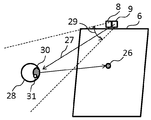
- FIG. 4 is a diagram illustrating an example of a gaze position calculation process.
- FIG. 5 is a diagram illustrating an example of eye feature amount detection.
- FIG. 6 is an example of a flowchart of the mode determination process of the mobile terminal 100 according to the first embodiment.
- an electronic device and a mode determination method are provided that can improve the operability when the user performs a touch operation.
- FIG. 1 is a schematic diagram of a hardware configuration of the mobile terminal 100 according to the first embodiment.
- a mobile phone such as a smartphone or a feature phone, a tablet computer, or a personal computer may be used as the mobile terminal 100.
- the mobile terminal 100 authenticates the user before executing a predetermined process.
- the predetermined process is, for example, a process of releasing the lock of the mobile terminal 100 or a process of accessing the user's private data.
- a mobile terminal 100 includes, as hardware components, a wireless communication circuit 2, a CPU 3, a ROM 4, a RAM 5, a display 6 that displays a screen, a finger, It includes a touch panel 7 that detects input from a touch pen or the like, a light source 8 that emits infrared light, and a camera 9 that captures an image.
- These hardware modules are interconnected by, for example, a bus.
- the mobile terminal 100 has a display area in which the touch panel 7 and the display 6 are overlapped, and the touch position detected on the touch panel 7 is provided so that the position on the screen displayed on the display 6 matches. It is done.
- the wireless communication circuit 2 is a means for communicating with an external device.
- the wireless communication circuit 2 is a means for connecting to a network such as a mobile communication network.
- the wireless communication circuit 2 is not essential in the present invention.
- ROM 4 stores various programs executed by CPU 3.
- the ROM 4 is a nonvolatile memory in which data is not lost even when the power is turned off.
- Examples of the various programs include an application program executed by the mobile terminal 100 and an OS (Operation System), which are held in the ROM 4 even when the mobile terminal 100 is turned off.
- the RAM 5 is used as a storage area in which the CPU 3 expands data such as the OS in the ROM 4.
- RAM Random Access Memory
- the CPU 3 reads out various programs stored in the ROM 4 and executes the various programs, whereby the wireless communication unit 10, the mode determination unit 11, the display unit 14, the touch operation detection unit 15, the light irradiation unit 16, and the image acquisition unit. 17, operates as the line-of-sight position calculation unit 18.
- the portable terminal 100 stores the OS in the ROM 4.
- the CPU 3 expands the OS data in the ROM 4 to the RAM 5, executes a program defined in advance by the OS, and displays a screen. After the screen display is performed, when the user enters an operation waiting state and a user operation is detected, an interrupt process is entered in the CPU 3, and a process predefined by the OS is executed for the user operation. .
- the display 6 includes a display panel that displays an image using a liquid crystal element or an organic EL (ElectroLuminescence) element, a drive circuit that drives the display panel, and the like.
- the touch panel 7 has a sensor provided so as to be superimposed on the display surface of the display 6, and supplies coordinate information representing a position instructed by the user to the mode determination unit 11.
- the sensor of the touch panel 7 is, for example, a capacitive sensor that senses a finger using electrostatic coupling with the finger.
- the light source 8 is provided near the upper side of the peripheral edge of the display 6, for example, and irradiates infrared rays.
- the camera 9 is provided near the upper side of the peripheral edge of the display 6, for example, and takes an image.
- FIG. 2 is a functional block diagram of the mobile terminal 100 according to the first embodiment.
- the mobile terminal 100 includes a wireless communication unit 10, a mode determination unit 11, a first storage unit 12, a second storage unit 13, a display unit 14, a touch operation detection unit 15, and light irradiation as functional blocks.
- Unit 16 image acquisition unit 17, and line-of-sight position calculation unit 18.
- the wireless communication unit 10 is connected to a network such as a mobile communication network using the wireless communication circuit 2.
- the mode determination unit 11 performs a mode determination process described later.
- the first storage unit 12 stores various programs using the ROM 4.
- storage part 13 stores the 1st relationship information 19 and the 2nd relationship information 20 which are mentioned later using RAM5.
- the display unit 14 displays a screen using the display 6.
- the touch operation detection unit 15 detects a touch operation using the touch panel 7.
- the light irradiation unit 16 irradiates infrared rays using the light source 8 that irradiates infrared rays.
- the image acquisition unit 17 captures an image using the camera 9.
- the line-of-sight position calculation unit 18 performs a line-of-sight position calculation process to be described later.
- the mobile terminal 100 has a handwriting input mode in which handwriting input is performed by a touch operation and a screen operation mode in which a screen operation such as movement of an input target area is performed by the touch operation.
- Touch panel 7 touch operation detection unit 15 that detects the position of the touch operation
- line-of-sight position calculation unit 18 that calculates the position of the user's line of sight on display 6, and mode determination unit 11.
- the mode determination unit 11 determines whether the handwriting operation mode or the screen operation mode is based on the relationship between the calculated line-of-sight position and the detected touch operation position.
- the mobile terminal 100 can improve the operability when the user operates by a touch operation.
- the handwriting input mode is a mode for accepting handwritten input such as input of characters written by touch operation or input drawn by touch operation.
- the screen operation mode is a mode for accepting a screen operation such as movement of an input target such as a photo or an image or scrolling of the screen.
- the relation information used when the mode determination part 11 determines whether it is handwriting input mode or screen operation mode is demonstrated.
- the present inventor has a significant relationship between the position of the line of sight on the display 6 and the position of the touch operation on the touch panel 7 when the user is performing handwritten input or performing a screen operation. Focused on. When the user is performing handwriting input, the position of the line of sight tends to follow the position of the touch operation and the moving direction. In addition, when the user performs a screen operation, the line-of-sight position tends to be located on the opposite side of the touch operation movement direction, and the line-of-sight movement is opposite to the touch operation movement direction. It turns out that there is a certain tendency.
- FIG. 3A is an image diagram of a handwriting input mode.
- FIG. 3B is an image diagram of the screen operation mode.
- the input object 21 and the locus 22 of the touch operation input by handwriting input are displayed on the display 6.
- the input object 21 in the display 6 is indicated by a solid line, and a portion outside the display range of the display 6 is indicated by a dotted line.
- the mobile terminal 100 performs handwriting input by a touch operation on the display area including the displayed input target 21.
- the finger 23 indicates a touch position that is currently touched.
- a dotted circle 24 indicates the range of the user's line of sight.
- the user's line of sight is located within a range indicated by a circle 24 with respect to the drawing by the touch operation.
- the size of the circle 24 depends on the range in which the line of sight is dispersed when the user is gazing at a specific point.
- the position of the line of sight indicates that the position of the touch operation follows the moving direction.
- the mode determination unit 11 determines the handwriting input mode using this relationship.
- the touch operation touching the display 6 having the touch panel 7 moves in the direction of the arrow 25 with respect to the display area including the input target 21 displayed on the display 6.
- the input object 21 can be moved.
- the user's line of sight is at the position of a circle 24 located on the opposite side of the touch operation movement direction with respect to the touch operation position.
- the mode determination unit 11 determines the screen operation mode using this relationship.
- the portable terminal 100 stores in the second storage unit 13 the relationship when determining the handwriting input mode as the first relationship information 19 and the relationship when determining the screen operation mode as the second relationship information 20.
- the first relation information 19 includes information indicating a predetermined range in which the calculated line-of-sight position on the display 6 is based on the detected position of the touch operation on the display 6, and a predetermined direction of the movement direction of the touch operation. Contains information indicating the range.
- the mode determination unit 11 determines that the handwriting input mode is set.
- the predetermined range based on the detected position of the touch operation on the display 6 is determined, for example, assuming a range in which the line of sight is dispersed when the user looks at the position of the touch operation. Further, the predetermined range of the moving direction of the touch operation is determined assuming a range in which the line of sight is dispersed based on the moving direction predicted from a plurality of touches detected by the touch operation.
- the second relation information 20 is information indicating a predetermined range on the opposite side of the moving direction based on the detected moving direction of the touch operation on the display 6 based on the detected position of the line of sight on the display 6.
- the first relation information 19 is information for determining whether or not the movement of the position of the line of sight calculated within a predetermined time from the start of the touch operation follows the position of the touch detected with the movement of the touch operation.
- the mode determination unit 11 determines the handwriting input mode when it is determined that the calculated line-of-sight position follows the position of the touch operation. Specifically, the mode determination unit 11 uses the first relationship information 19 to perform the detected first touch operation on each of the touch operation positions detected at predetermined time intervals. It is determined whether or not the position of the line of sight calculated within the predetermined range from the position of the touch operation exists within a predetermined period from the time when the first touch operation is performed.
- the mode determination unit 11 performs the second touch operation.
- the position of the line of sight calculated within the predetermined range from the second touch coordinates exists within a predetermined period from the time, it is determined that the line of sight follows the touch operation, and the handwriting input mode is determined.
- the second relation information 20 is information for determining whether or not the movement of the position of the line of sight detected within a predetermined time from the start of the touch operation reverses the movement of the touch operation.
- the mode determination unit 11 determines the screen operation mode when it is determined that the movement of the calculated line-of-sight position is opposite to the movement of the touch operation.
- the first relation information 19 is information used for determining whether or not the touch operation and the movement of the position of the line of sight are approximated using linear approximation.
- the mode determination unit 11 performs straight line approximation using the coordinates of a plurality of positions of the detected touch operation, and calculates the slope of the straight line.
- the mode determination unit 11 performs straight line approximation using the calculated coordinates of the plurality of positions of the line of sight, and calculates the slope of the straight line.
- the mode determination unit 11 determines whether or not each inclination difference is within the approximate range indicated by the first relationship information 19, and when each inclination difference is within the range, the handwriting input mode and judge.
- the average of the coordinates of a plurality of positions may be calculated for each fixed period, and linear approximation may be performed on the coordinate group for which the average is calculated.
- the second relation information 20 is information indicating a predetermined range from a straight line calculated using linear approximation from the movement of the touch operation position.
- the predetermined range is a range in which the line of sight is assumed to be dispersed from a straight line before the position of the touch operation detected last.
- the mode determination unit 11 determines the screen operation mode when the calculated line-of-sight position corresponds to the second relationship information 20.
- FIG. 4 is a diagram illustrating an example of a gaze position calculation process.
- FIG. 5 is a diagram illustrating an example of eye feature amount detection.
- the line-of-sight position calculation unit 18 calculates the line-of-sight position 26 of the user on the display 6 as shown in FIG.
- the line-of-sight position calculation unit 18 can calculate the position 26 of the line of sight of the user irradiated with the infrared rays 27 from the light source 8 from the captured image acquired by the image acquisition unit 17 using the camera 9.
- the camera 9 and the light source 8 are provided at a position where the user's eyes 28 can be photographed, for example, near the upper side of the peripheral portion of the display 6.
- the light irradiation unit 16 irradiates the face of the user looking at the display 6 with infrared rays 27.
- the camera 9 shoots so that the user's face is included in the shooting range 29.
- the camera 9 can photograph the user's eyes 28.
- the line-of-sight position calculation unit 18 acquires a captured image captured by the camera 9.
- the line-of-sight position calculation unit 18 extracts a cornea reflection image 31 in which the infrared rays 27 that are irradiation light from the pupil 30 and the light source 8 are reflected from the eyeball surface by image processing from the acquired captured image, and the feature amount of the user's eye 28 Is detected.
- FIG. 5 shows an example of eye feature amount detection for calculating the distance between the user's eye 28 and the display 6 and the angle of the user's line of sight.
- the line-of-sight position calculation unit 18 acquires a binocular distance (interpupillary distance) 34 between the left eye 32 and the right eye 33 from the captured image, and the user's eyes 28 and the display surface of the display 6 are displayed. Get the distance.
- the line-of-sight position calculation unit 18 can calculate the distance between the user's eye 28 and the display surface of the display 6 from the number of pixels between the pupils in the captured image.
- the binocular distance (interpupillary distance) 34 between the left eye 32 and the right eye 33 is about 65 mm (about 62 mm to 68 mm) in the case of an adult.
- the distance between the user's eyes 28 and the display surface of the display 6 may be a fixed value based on a standard posture, or may be a set value according to the user. Further, the line-of-sight position calculation unit 18 may acquire the distance between the user's eye 28 and the display surface of the display 6 from the captured image based on the intensity of reflected light of the infrared ray 27.
- the line-of-sight position calculation unit 18, for at least one of the user's eyes 28, has a horizontal distance 35 between the pupil 30 and the corneal reflection image 31 (a pupil-to-reflection horizontal distance) 35, and a vertical direction between the pupil 30 and the corneal reflection image 31.
- the distance (pupil / reflection vertical distance) 36 can be calculated.
- the line-of-sight position calculation unit 18 can make the positional relationship with the camera 9, the light source 8, and the display 6 known.
- the line-of-sight position calculation unit 18 may set the positional relationship with the camera 9, the light source 8, and the display 6 as a fixed value or a set value, for example.
- the line-of-sight position calculation unit 18 calculates the angle of the line of sight from the pupil-reflection horizontal distance 35 and the pupil-reflection vertical distance 36.
- the line-of-sight position calculation unit 18 can calculate the line-of-sight position 26 of the user on the display 6 from the calculated line-of-sight angle and the distance between the user's eyes 28 and the display surface of the display 6.
- FIG. 6 is an example of a flowchart of the mode determination process of the mobile terminal 100 according to the first embodiment.
- the mode determination unit 11 of the mobile terminal 100 determines whether the handwriting input mode or the screen operation mode is used by using the first relation information 19 and the second relation information 20 described above.
- the mode determination unit 11 acquires a touch operation on the touch panel 7 from the touch operation detection unit 15 (S001).
- the mode determination unit 11 determines what type of touch operation the acquired touch operation is (S002).
- the types of touch operations include rotation to rotate the screen when touched at two points, pinch to touch the screen to reduce or enlarge the screen at one point, tap operation to select a selected image by touching at one point, one point Touch operation (which corresponds to swipe or handwriting input for moving the screen or the input target) that is continuously touched to move the position of the touch operation.
- the mode determination unit 11 determines whether the touch operation determined in step S002 is a touch operation in which the position of the touch operation continuously moves (swipe or handwriting input for moving the screen or the input target) (S003). ).
- the line-of-sight position calculation unit 18 calculates the position of the user's line of sight by the above-described line-of-sight position calculation process. (S004).
- the touch operation is not a touch operation that continuously moves the position of the touch operation (S003: No)
- the mode determination unit 11 compares the position of the line of sight on the display 6 calculated by the line-of-sight position detection process in step S004 with the position of the touch operation (S005).
- the mode determination unit 11 determines whether or not the comparison result between the position of the line of sight and the position of the touch operation corresponds to the first relation information 19 described above (S006).
- the mode determination unit 11 determines the operation mode as the handwriting input mode, Switch to handwriting input mode (S007). If the current operation mode is the handwriting input mode, it is left as it is.
- the mode determination unit 11 determines the position of the line of sight and the position of the touch operation. It is determined whether or not the comparison result corresponds to the second relation information 20 described above (S008).
- the mode determination unit 11 determines the operation mode as the screen operation mode, Switch to the screen operation mode (S009). If the current operation mode is the screen operation mode, it is left as it is. On the other hand, when it is determined that the comparison result between the position of the line of sight and the position of the touch operation does not correspond to the above-described second relation information 20 (S008: No), the mode determination unit 11 switches from the current operation mode. Without waiting for a touch operation to be acquired again in step S001.
- the mode intended by the user when the touch operation is performed, the mode intended by the user can be determined by using the position of the line of sight having a significant relationship with the touch operation.
- the operability when the user operates by touch operation can be improved.
- the electronic device is applied to the portable terminal 100 such as a smartphone or a tablet computer.
- the present invention is not limited to this, and the electronic device can be applied to a desktop computer or the like. .
- Antenna 2 Wireless communication circuit 3: CPU 4: ROM 5: RAM 6: Display 7: Touch panel 8: Light source 9: Camera 10: Wireless communication unit 11: Mode determination unit 12: First storage unit 13: Second storage unit 14: Display unit 15: Touch operation detection unit 16: Light irradiation unit 17 : Image acquisition unit 18: Eye position calculation unit 19: First relation information 20: Second relation information 21: Input object 22: Touch operation locus 23: Finger 24: Circle 25: Arrow 26: User's eye position 27: Infrared 28: User's eye 29: Imaging range 30: Pupil 31: Cornea reflection image 32: Left eye 33: Right eye 34: Interpupillary distance 35: Pupil-reflection horizontal distance 36: Pupil-reflection vertical distance 100: Mobile phone Terminal
Landscapes
- Engineering & Computer Science (AREA)
- General Engineering & Computer Science (AREA)
- Theoretical Computer Science (AREA)
- Human Computer Interaction (AREA)
- Physics & Mathematics (AREA)
- General Physics & Mathematics (AREA)
- User Interface Of Digital Computer (AREA)
Abstract
【課題】ユーザがタッチ操作によって電子機器を操作する際の操作性を向上させる。 【解決手段】タッチ操作により手書き入力が行われる手書き入力モードと、タッチ操作により画面の操作が行われる画面操作モードとを有する電子機器であって、前記タッチ操作が行われるディスプレイと、前記タッチ操作の位置を検出するタッチ操作検出部と、前記ディスプレイ上のユーザの視線の位置を算出する視線位置算出部と、前記算出された視線の位置と前記検出されたタッチ操作の位置との関係に基づき、前記手書き入力モードか前記画面操作モードかを判定するモード判定部とを備えることを特徴とする電子機器。
Description
本技術は、電子機器、モード判定方法およびモード判定プログラムに関する。
近年、タッチパネルを有する携帯電話端末、携帯情報端末、タブレット型端末等の電子機器が多用されている。
これら、タッチパネルを有する電子機器において、さまざまなアプリケーションが動作する。その一例として、タッチ操作による手書き入力が行われるアプリケーションがある。当該アプリケーションでは、写真や画像などの入力対象領域を背景として、手書き入力を行える(特許文献1)。
入力対象領域を背景として手書き入力が行われる電子機器において、ディスプレイのサイズよりも写真や画像などの入力対象領域のサイズが大きい場合がある。この場合、入力対象領域の一部はディスプレイ内に表示しきれない。このため、入力対象領域の表示しきれない部分をディスプレイ内に表示して手書き入力を行うために、ユーザは入力対象領域を移動させる画面の操作を行う必要がある。そこで、手書き入力が行われる手書き入力モードと、画面の操作が行われる画面操作モードとを切り替えることが考えられる。
手書き入力モードと画面操作モードとを切り替える方法として、モード切り替え用の操作ボタンを画面上に表示し、ユーザに選択させる方法が考えられる。また、ユーザの複数の指を用いて操作を行うマルチタッチを用いて、手書き入力モードと画面操作モードとを切り替える方法が考えられる。たとえば、指一本での入力であれば、手書き入力モードと判定し、指二本での入力であれば、画面操作モードと判定する。
しかしながら、モード切り替え用の操作ボタンを用いて、手書き入力モードと画面操作モードとを切り替える場合、ユーザは手書き入力を行いたい場合や、画面操作を行いたい場合にそれぞれ、モード切り替え用の操作ボタンを選択しなければならず、余計な手間がかかってしまう。
また、マルチタッチを用いて、手書き入力モードと画面操作モードとを切り替える場合、ユーザが切り替えたいモードの操作方法を予め認識し、区別して行わなければならないなど、操作の複雑性が増す。
本発明は、上記の問題点を鑑みたものであり、ユーザがタッチ操作によって電子機器を操作する際の操作性を向上させることができる電子機器、モード判定方法およびモード判定プログラムを提供することを目的とする。
開示の技術の一観点によれば、タッチ操作により手書き入力が行われる手書き入力モードと、タッチ操作により画面の操作が行われる画面操作モードとを有する電子機器であって、前記タッチ操作が行われるディスプレイと、前記タッチ操作の位置を検出するタッチ操作検出部と、前記ディスプレイ上のユーザの視線の位置を算出する視線位置算出部と、前記算出された視線の位置と前記検出されたタッチ操作の位置との関係に基づき、前記手書き入力モードか前記画面操作モードかを判定するモード判定部とを備えることを特徴とする電子機器が提供される。
開示の技術の一観点によれば、ユーザがタッチ操作によって電子機器を操作する際の操作性を向上させることができる電子機器、モード判定方法およびモード判定プログラムを提供することができる。
本件では、ユーザがタッチ操作によって操作する際の操作性を向上させることができる電子機器およびモード判定方法を提供する。
以下に、電子機器およびモード判定方法の実施例を図面に基づいて詳細に説明する。なお、この実施例は、開示の技術を限定するものではない。
(第1の実施形態)
(携帯端末のハードウェア構成)
図1は、第1の実施形態に係る携帯端末100のハードウェア構成の概略図である。第1の実施形態では、携帯端末100として、例えば、スマートフォンやフィーチャーフォンなどの携帯電話機、タブレットコンピュータ、パーソナルコンピュータ等を使用してもよい。
(携帯端末のハードウェア構成)
図1は、第1の実施形態に係る携帯端末100のハードウェア構成の概略図である。第1の実施形態では、携帯端末100として、例えば、スマートフォンやフィーチャーフォンなどの携帯電話機、タブレットコンピュータ、パーソナルコンピュータ等を使用してもよい。
携帯端末100は、所定の処理を実行する前に、ユーザの認証を行う。所定の処理は、例えば、携帯端末100のロックを解除する処理や、ユーザのプライベートなデータにアクセスする処理などである。
図1に示すように、携帯端末100は、ハードウェアの構成要素として、アンテナ1に接続される無線通信回路2と、CPU3と、ROM4と、RAM5と、画面を表示するディスプレイ6と、指やタッチペンなどによる入力を検出するタッチパネル7と、赤外線を照射する光源8と、画像を撮影するカメラ9を有する。これらのハードウェアモジュール(ハードウェアの構成要素)は、例えば、バスにより相互接続される。携帯端末100は、タッチパネル7とディスプレイ6が重ねて設けられた表示領域を有し、タッチパネル7上で検出されたタッチ位置が、ディスプレイ6に表示される画面上の位置とが一致するように設けられる。
無線通信回路2は、外部装置と通信するための手段である。無線通信回路2は、本実施形態においては、移動通信網等のネットワークに接続するための手段である。なお、無線通信回路2は、本発明にあっては必須ではない。
ROM4は、CPU3により実行される各種プログラムを格納する。ROM4は、電源を切ってもデータが消えない不揮発性のメモリである。各種プログラムとしては、例えば、携帯端末100が実行するアプリケーションプログラムやOS(Operation System)などがあり、これらは携帯端末100の電源が切れてもROM4に保持される。
RAM5は、CPU3が、ROM4内のOSなどのデータを展開する記憶領域として用いられる。例えば、RAM(Random Access Memory)などを使用してもよい。
CPU3は、ROM4に格納された各種プログラムを読み出して、各種プログラムを実行することで、無線通信部10、モード判定部11、表示部14、タッチ操作検出部15、光照射部16、画像取得部17、視線位置算出部18として動作する。
携帯端末100は、ROM4内にOSを格納する。携帯端末100の電源が入れられると、CPU3が、ROM4内のOSのデータをRAM5に展開し、OSで予め定義されているプログラムが実行され、画面表示が行われる。画面表示が行われた後に、ユーザの操作待ち状態となり、ユーザの操作が検出された際に、CPU3に割り込み処理が入り、ユーザの操作に対して、OSで予め定義された処理が実行される。
ディスプレイ6は、液晶素子や有機EL(ElectroLuminescence)素子により画像を表示する表示パネルと、表示パネルを駆動する駆動回路等を有する。タッチパネル7は、ディスプレイ6の表示面に重ねて設けられるセンサを有し、ユーザに指示された位置を表す座標情報をモード判定部11に供給する。タッチパネル7のセンサは、例えば、指との静電結合を利用して指を感知する静電容量方式のセンサである。
光源8は、例えば、ディスプレイ6の周縁部の上側付近に設けられ、赤外線を照射する。
カメラ9は、例えば、ディスプレイ6の周縁部の上側付近に設けられ、画像を撮影する。
(携帯端末の機能ブロック)
次に、第1の実施形態に係る携帯端末100の機能ブロックについて説明する。図2は、第1の実施形態に係る携帯端末100の機能ブロック図である。
次に、第1の実施形態に係る携帯端末100の機能ブロックについて説明する。図2は、第1の実施形態に係る携帯端末100の機能ブロック図である。
図2に示すように、携帯端末100は、機能ブロックとして、無線通信部10、モード判定部11、第1記憶部12、第2記憶部13、表示部14、タッチ操作検出部15、光照射部16、画像取得部17、視線位置算出部18を有する。
無線通信部10は、無線通信回路2を用いて移動通信網等のネットワークに接続する。
モード判定部11は、後述するモード判定処理を行う。
第1記憶部12は、ROM4を用いて各種プログラムを格納する。第2記憶部13は、RAM5を用いて、後述する第1関係情報19および第2関係情報20を格納する。
表示部14は、ディスプレイ6を用いて画面を表示する。タッチ操作検出部15は、タッチパネル7を用いてタッチ操作を検出する。
光照射部16は、赤外線を照射する光源8を用いて赤外線を照射する。画像取得部17は、カメラ9を用いて画像を撮影する。視線位置算出部18は、後述する視線位置算出処理を行う。
第1の実施形態において、携帯端末100は、タッチ操作により手書き入力が行われる手書き入力モードとタッチ操作により入力対象領域の移動などの画面操作が行われる画面操作モードを有し、タッチ操作が行われるタッチパネル7と、タッチ操作の位置を検出するタッチ操作検出部15と、ディスプレイ6上のユーザの視線の位置を算出する視線位置算出部18と、モード判定部11とを有する。モード判定部11は、算出された視線の位置と検出されたタッチ操作の位置との関係に基づき、手書き操作モードか画面操作モードかを判定する。
これによって、携帯端末100は、ユーザがタッチ操作によって操作する際の操作性を向上させることができる。
(モード判定の判定基準)
手書き入力モードは、タッチ操作によって書かれた文字の入力や、タッチ操作によって描画される入力などの手書き入力を受け付けるモードである。画面操作モードは、写真や画像などの入力対象の移動、画面のスクロールなどの画面操作を受け付けるモードである。
手書き入力モードは、タッチ操作によって書かれた文字の入力や、タッチ操作によって描画される入力などの手書き入力を受け付けるモードである。画面操作モードは、写真や画像などの入力対象の移動、画面のスクロールなどの画面操作を受け付けるモードである。
モード判定部11が手書き入力モードか画面操作モードかを判定する際に用いる関係情報について説明する。
本件発明者は、ユーザが手書き入力を行っているとき、または、画面操作を行っているときのディスプレイ6上の視線の位置とタッチパネル7上のタッチ操作の位置とに有意な関係性があることに着目した。ユーザが手書き入力を行っているときは、視線の位置は、タッチ操作の位置、移動方向に追従する傾向が高い。また、ユーザが画面操作を行っているときは、視線の位置は、タッチ操作の位置に対し、タッチ操作の移動方向と逆側に位置する傾向、視線の移動がタッチ操作の移動方向と逆である傾向が高いことが分かった。
ここで、手書き入力モードと画面操作モードについて説明する。図3Aは、手書き入力モードのイメージ図である。図3Bは画面操作モードのイメージ図である。
手書き入力モードでは、図3Aに示すように、ディスプレイ6に入力対象21と手書き入力により入力されたタッチ操作の軌跡22が表示される。ディスプレイ6内の入力対象21は、実線で示し、ディスプレイ6の表示範囲外の部分は、点線で示す。携帯端末100は、表示された入力対象21を含む表示領域に対して、タッチ操作により手書き入力が行われる。図3Aにおいて、指23は現在タッチされているタッチ位置を示す。点線の円24は、ユーザの視線の範囲を示す。
手書き入力モードにおいて、ユーザが手書き入力を行う場合、タッチ操作による描画に対し、ユーザの視線は、円24で示す範囲に位置する。円24の大きさは、ユーザが特定の点を注視している時に、視線が分散する範囲による。ユーザが手書き入力を行っているときは、視線の位置は、タッチ操作の位置、移動方向に追従することを示す。モード判定部11はこの関係性を用いて手書き入力モードと判定する。
画面操作モードでは、図3Bに示すように、ディスプレイ6に表示された入力対象21を含む表示領域に対して、タッチパネル7を有するディスプレイ6にタッチしたタッチ操作が矢印25方向へ移動することによって、入力対象21を移動することができる。画面操作モードにおいて、ユーザが入力対象21の移動を行う場合、ユーザの視線は、タッチ操作の位置に対して、タッチ操作の移動方向と逆側に位置する円24の位置にある。モード判定部11は、この関係性を用いて画面操作モードと判定する。
以下に、関係性の具体例を説明する。
携帯端末100は、手書き入力モードと判定する場合の関係性を第1関係情報19とし、画面操作モードと判定する場合の関係性を第2関係情報20として、第2記憶部13に格納する。
第1関係情報19および第2関係情報20の第1の例を説明する。第1関係情報19は、算出されたディスプレイ6上の視線の位置が、検出されたディスプレイ6上のタッチ操作の位置を基準とした所定の範囲を示す情報と、タッチ操作の移動方向の所定の範囲を示す情報を含む。算出された視線の位置が、第1関係情報19のいずれかに該当する場合は、モード判定部11は、手書き入力モードと判定する。検出されたディスプレイ6上のタッチ操作の位置を基準とした所定の範囲は、例えば、ユーザがタッチ操作の位置を見た場合に視線が分散する範囲を想定して決定される。また、タッチ操作の移動方向の所定の範囲は、タッチ操作によって検出される複数のタッチから予測される移動方向に基づいて、視線が分散する範囲を想定して決定される。
第2関係情報20は、算出されたディスプレイ6上の視線の位置が、検出されたディスプレイ6上のタッチ操作の移動方向に基づいて、移動方向と反対側の所定の範囲を示す情報である。タッチ操作の移動方向に対して、タッチ操作開始から所定時間内に検出された視線が、タッチ操作の始点から所定の範囲内に多い(例えば、70%以上)場合、画面操作とする。
第1関係情報19および第2関係情報20の第2の例を説明する。第1関係情報19は、タッチ操作開始から所定時間内に算出された視線の位置の移動が、タッチ操作の移動に伴い検出されるタッチの位置に追従するか否かを判定する情報である。モード判定部11は、算出された視線の位置が、タッチ操作の位置に追従していると判定された場合、手書き入力モードと判定する。具体的には、モード判定部11は、当該第1関係情報19を用いて、所定時間間隔で検出されるタッチ操作の位置それぞれに対し、検出された第1のタッチ操作が行われた場合、第1のタッチ操作が行われた時刻から所定の期間内にタッチ操作の位置から所定範囲内に算出された視線の位置が存在するか判定する。さらに、モード判定部11は、当該第1関係情報19を用いて、第1のタッチ操作に連続して検出される第2のタッチ操作が行われた場合、第2のタッチ操作が行われた時刻から所定の期間内に第2のタッチ座標から所定範囲内に算出された視線の位置が存在する場合、視線がタッチ操作に追従していると判定し、手書き入力モードと判定する。
第2関係情報20は、タッチ操作開始から所定時間内に検出された視線の位置の移動が、タッチ操作の移動に対して逆行するか否かを判定する情報である。モード判定部11は、算出された視線の位置の移動が、タッチ操作の移動に逆行していると判定された場合、画面操作モードと判定する。
第1関係情報19および第2関係情報20の第3の例を説明する。第1関係情報19は、タッチ操作と視線の位置の移動を、直線近似を用いて比較する際に、近似しているか否かの判定に用いる情報である。モード判定部11は、検出されたタッチ操作の複数の位置の座標を用いて直線近似を行い、直線の傾きを算出する。モード判定部11は、算出された視線の複数の位置の座標を用いて直線近似を行い、直線の傾きを算出する。モード判定部11は、それぞれの傾きの差分が第1関係情報19で示した近似の範囲内であるか否かを判定し、それぞれの傾きの差分が当該範囲内である場合、手書き入力モードと判定する。ここで、直線近似を行う際に、複数の位置の座標を一定期間ごとに平均を算出し、平均を算出した座標群に対して、直線近似を行うこととしてもよい。
第2関係情報20は、タッチ操作位置の移動から直線近似を用いて算出された直線から所定の範囲を示す情報である。所定の範囲とは、最後に検出されたタッチ操作の位置よりも前の直線から視線が分散すると想定される範囲である。モード判定部11は、算出された視線の位置が当該第2関係情報20に該当する場合に、画面操作モードと判定する。
(視線位置算出処理)
ここで、図4、図5を用いて、視線位置算出処理について詳細に説明する。図4は、視線位置算出処理の一例を示す図である。図5は、眼の特徴量検出の一例を示す図である。
ここで、図4、図5を用いて、視線位置算出処理について詳細に説明する。図4は、視線位置算出処理の一例を示す図である。図5は、眼の特徴量検出の一例を示す図である。
視線位置算出部18は、図4に示すように、ディスプレイ6上のユーザの視線の位置26を算出する。視線位置算出部18は、カメラ9を用いて画像取得部17によって取得した撮影画像から、光源8からの赤外線27が照射されたユーザの視線の位置26を算出することができる。
カメラ9と光源8は、ユーザの眼28を撮影可能な位置、例えば、ディスプレイ6の周縁部の上側付近に設けられる。光照射部16は、ディスプレイ6を見るユーザの顔に赤外線27を照射する。カメラ9は、ユーザの顔を撮影範囲29に含むようにして撮影する。カメラ9は、ユーザの眼28を撮影することができる。
視線位置算出部18は、カメラ9が撮影した撮影画像を取得する。視線位置算出部18は、取得した撮影画像から画像処理により、瞳孔30と光源8からの照射光である赤外線27が眼球表面で反射した角膜反射像31を抽出し、ユーザの眼28の特徴量を検出する。
図5に、ユーザの眼28とディスプレイ6との距離や、ユーザの視線の角度を算出するための、眼の特徴量検出の一例を示す。
図5に示すように、視線位置算出部18は、撮影画像から左眼32と右眼33の両眼距離(瞳孔間距離)34を取得し、ユーザの眼28とディスプレイ6の表示面との距離を取得する。視線位置算出部18は、撮影画像における瞳孔間の画素数から、ユーザの眼28とディスプレイ6の表示面との距離を計算することができる。一般に、左眼32と右眼33の両眼距離(瞳孔間距離)34は、成人の場合において、約65mm(62mmから68mm程度)である。なお、ユーザの眼28とディスプレイ6の表示面との距離は、標準的な姿勢に基づく固定値としてもよいし、ユーザに応じた設定値としてもよい。また、視線位置算出部18は、赤外線27の反射光の強度に基づいて、撮影画像からユーザの眼28とディスプレイ6の表示面との距離を取得してもよい。
視線位置算出部18は、ユーザの眼28の少なくとも一方について、瞳孔30と角膜反射像31の水平方向の距離(瞳孔・反射間水平距離)35と、瞳孔30と角膜反射像31の垂直方向の距離(瞳孔・反射間垂直距離)36とを計算することができる。視線位置算出部18は、カメラ9、光源8、およびディスプレイ6との位置関係を既知とすることができる。視線位置算出部18は、カメラ9、光源8、およびディスプレイ6との位置関係を、例えば、固定値としてもよいし、設定値としてもよい。視線位置算出部18は、瞳孔・反射間水平距離35と瞳孔・反射間垂直距離36から視線の角度を算出する。
視線位置算出部18は、算出した視線の角度と、ユーザの眼28とディスプレイ6の表示面との距離とから、ディスプレイ6上のユーザの視線の位置26を算出することができる。
(モード判定処理)
具体的なモード判定処理について、図6を用いて説明する。図6は、第1の実施形態に係る携帯端末100のモード判定処理のフローチャートの一例である。
具体的なモード判定処理について、図6を用いて説明する。図6は、第1の実施形態に係る携帯端末100のモード判定処理のフローチャートの一例である。
携帯端末100のモード判定部11は、上述した第1関係情報19および第2関係情報20を用いて手書き入力モードか画面操作モードかを判定する。
モード判定部11は、タッチパネル7へのタッチ操作をタッチ操作検出部15から取得する(S001)。
モード判定部11は、取得したタッチ操作がどのような種類のタッチ操作か判定する(S002)。タッチ操作の種類としては、2点でタッチされて画面を回転させるローテート、2点でタッチされて画面の縮小拡大を行うピンチ、1点でタッチされて選択画像などを選択するタップ操作、1点でタッチされて、連続的にタッチ操作の位置が移動するタッチ操作(画面や入力対象の移動を行うスワイプまたは手書き入力に該当)などがある。
モード判定部11は、ステップS002で判定されたタッチ操作が、連続的にタッチ操作の位置が移動するタッチ操作(画面や入力対象の移動を行うスワイプまたは手書き入力)であるかを判定する(S003)。ステップS003において、タッチ操作が連続的にタッチ操作の位置移動するタッチ操作である場合(S003:Yes)、視線位置算出部18は、上述の視線位置算出処理により、ユーザの視線の位置を算出する(S004)。一方、ステップS003において、タッチ操作が連続的にタッチ操作の位置移動するタッチ操作でない場合(S003:No)、再度ステップS001でタッチ操作を取得することを待機する。
モード判定部11は、ステップS004における視線位置検出処理によって算出されたティスプレイ6上の視線の位置と、タッチ操作の位置とを比較する(S005)。
モード判定部11は、視線の位置とタッチ操作の位置との比較結果が、上述の第1関係情報19に該当するか否かを判定する(S006)。
視線の位置とタッチ操作の位置との比較結果が、上述の第1関係情報19に該当すると判定された場合(S006:Yes)、モード判定部11は、操作モードを手書き入力モードと判定し、手書き入力モードへ切り替える(S007)。現状の操作モードが手書き入力モードである場合は、そのままとする。
視線の位置とタッチ操作の位置との比較結果が、上述の第1関係情報19に該当しないと判定された場合(S006:No)、モード判定部11は、視線の位置とタッチ操作の位置との比較結果が、上述の第2関係情報20に該当するか否かを判定する(S008)。
視線の位置とタッチ操作の位置との比較結果が、上述の第2関係情報20に該当すると判定された場合(S008:Yes)、モード判定部11は、操作モードを画面操作モードと判定し、画面操作モードへ切り替える(S009)。現状の操作モードが画面操作モードである場合は、そのままとする。一方、視線の位置とタッチ操作の位置との比較結果が、上述の第2関係情報20に該当しないと判定された場合(S008:No)、モード判定部11は、現状の操作モードからの切り替えを行なわず、再度ステップS001でタッチ操作を取得することを待機する。
第1の実施形態のモード判定方法によれば、タッチ操作を行った際に、タッチ操作と有意な関係性を有する視線の位置を用いることによって、ユーザの意図するモードを判定することができるため、ユーザがタッチ操作によって操作する際の操作性を向上させることができる。
第1の実施形態では、電子機器として例えばスマートフォンやタブレットコンピュータ等の携帯端末100に適用するとしているが、これに限定されるものではなく、電子機器として例えばデスクトップコンピュータ等にも適用することができる。
1:アンテナ
2:無線通信回路
3:CPU
4:ROM
5:RAM
6:ディスプレイ
7:タッチパネル
8:光源
9:カメラ
10:無線通信部
11:モード判定部
12:第1記憶部
13:第2記憶部
14:表示部
15:タッチ操作検出部
16:光照射部
17:画像取得部
18:視線位置算出部
19:第1関係情報
20:第2関係情報
21:入力対象
22:タッチ操作の軌跡
23:指
24:円
25:矢印
26:ユーザの視線の位置
27:赤外線
28:ユーザの眼
29:撮影範囲
30:瞳孔
31:角膜反射像
32:左眼
33:右眼
34:瞳孔間距離
35:瞳孔・反射間水平距離
36:瞳孔・反射間垂直距離
100:携帯端末
2:無線通信回路
3:CPU
4:ROM
5:RAM
6:ディスプレイ
7:タッチパネル
8:光源
9:カメラ
10:無線通信部
11:モード判定部
12:第1記憶部
13:第2記憶部
14:表示部
15:タッチ操作検出部
16:光照射部
17:画像取得部
18:視線位置算出部
19:第1関係情報
20:第2関係情報
21:入力対象
22:タッチ操作の軌跡
23:指
24:円
25:矢印
26:ユーザの視線の位置
27:赤外線
28:ユーザの眼
29:撮影範囲
30:瞳孔
31:角膜反射像
32:左眼
33:右眼
34:瞳孔間距離
35:瞳孔・反射間水平距離
36:瞳孔・反射間垂直距離
100:携帯端末
Claims (10)
- タッチ操作により手書き入力が行われる手書き入力モードと、タッチ操作により画面の操作が行われる画面操作モードとを有する電子機器であって、
前記タッチ操作が行われるディスプレイと、
前記タッチ操作の位置を検出するタッチ操作検出部と、
前記ディスプレイ上のユーザの視線の位置を算出する視線位置算出部と、
前記算出された視線の位置と前記検出されたタッチ操作の位置との関係に基づき、前記手書き入力モードか前記画面操作モードかを判定するモード判定部と
を備えることを特徴とする電子機器。
- 前記モード判定部は、
前記算出された視線の位置が、前記検出されたタッチ操作の位置を基準とした第1の範囲に存在する、または前記検出されたタッチ操作の移動方向に対して第2の範囲に存在する場合、前記手書き操作モードと判定することを特徴とする請求項1に記載の電子機器。
- 前記第1の範囲および前記第2の範囲は、ユーザが前記タッチ操作の位置を見たときに視線の位置が分散する範囲に基づいて設定されることを特徴とする請求項2に記載の電子機器。
- 前記モード判定部は、
前記算出された視線の位置が、前記検出されたタッチ操作の移動方向に対して、反対側の所定の範囲に存在する場合、前記画面操作モードと判定することを特徴とする請求項1~3のいずれか一項に記載の電子機器。
- 前記モード判定部は、
前記算出された視線の位置の移動が、前記検出されたタッチ操作の移動方向に対して追従すると判定される場合、前記手書き操作モードと判定することを特徴とする請求項1~4のいずれか一項に記載の電子機器。
- 前記モード判定部は、
前記算出された視線の位置の移動が、前記検出されたタッチ操作の移動方向に対して逆行すると判定される場合、前記画面操作モードと判定することを特徴とする請求項1~5のいずれか一項に記載の電子機器。
- 前記モード判定部は、
複数の前記算出された視線の位置から算出された第1の近似直線の傾きと、複数の前記検出されたタッチ操作の位置から算出された第2の近似直線の傾きとを比較し、前記第1の近似直線の傾きと前記第2の近似直線の傾きとの差分が所定値以下である場合、前記手書き操作モードと判定することを特徴とする請求項1~6のいずれか一項に記載の電子機器。
- 前記視線位置算出部は、
前記ユーザの眼を含む撮影画像を取得し、
前記取得した撮影画像から、前記視線の角度を算出し、
前記算出された視線の角度と、前記ユーザの眼と前記ディスプレイとの距離とに基づき、前記ディスプレイ上のユーザの視線の位置を算出することを特徴とする請求項1~7のいずれか一項に記載の電子機器。
- タッチ操作により手書き入力が行われる手書き入力モードと、タッチ操作により画面の操作が行われる画面操作モードとを有する電子機器のモード判定方法であって、
ディスプレイ上の前記タッチ操作の位置を検出し、
前記ディスプレイ上のユーザの視線の位置を算出し、
前記算出された視線の位置と前記検出されたタッチ操作の位置との関係に基づき、前記手書き入力モードか前記画面操作モードかを判定する
ことを特徴とするモード判定方法。
- タッチ操作により手書き入力が行われる手書き入力モードと、タッチ操作により画面の操作が行われる画面操作モードとを有する電子機器に用いるモード判定プログラムであって、
ディスプレイ上の前記タッチ操作の位置を検出し、
前記ディスプレイ上のユーザの視線の位置を算出し、
前記算出された視線の位置と前記検出されたタッチ操作の位置との関係に基づき、前記手書き入力モードか前記画面操作モードかを判定する
ことを特徴とするモード判定プログラム。
Priority Applications (1)
| Application Number | Priority Date | Filing Date | Title |
|---|---|---|---|
| PCT/JP2014/003367 WO2015198366A1 (ja) | 2014-06-23 | 2014-06-23 | 電子機器、モード判定方法およびモード判定プログラム |
Applications Claiming Priority (1)
| Application Number | Priority Date | Filing Date | Title |
|---|---|---|---|
| PCT/JP2014/003367 WO2015198366A1 (ja) | 2014-06-23 | 2014-06-23 | 電子機器、モード判定方法およびモード判定プログラム |
Publications (1)
| Publication Number | Publication Date |
|---|---|
| WO2015198366A1 true WO2015198366A1 (ja) | 2015-12-30 |
Family
ID=54937507
Family Applications (1)
| Application Number | Title | Priority Date | Filing Date |
|---|---|---|---|
| PCT/JP2014/003367 Ceased WO2015198366A1 (ja) | 2014-06-23 | 2014-06-23 | 電子機器、モード判定方法およびモード判定プログラム |
Country Status (1)
| Country | Link |
|---|---|
| WO (1) | WO2015198366A1 (ja) |
Citations (3)
| Publication number | Priority date | Publication date | Assignee | Title |
|---|---|---|---|---|
| JP2009251658A (ja) * | 2008-04-01 | 2009-10-29 | Fujifilm Corp | 携帯型電子装置及びその制御方法 |
| JP2012203671A (ja) * | 2011-03-25 | 2012-10-22 | Nec Casio Mobile Communications Ltd | 電子機器、情報生成方法及びプログラム |
| JP2013524390A (ja) * | 2010-04-16 | 2013-06-17 | クアルコム,インコーポレイテッド | 仮想キーボード寸法をユーザの指のサイズに動的に相関させるための装置および方法 |
-
2014
- 2014-06-23 WO PCT/JP2014/003367 patent/WO2015198366A1/ja not_active Ceased
Patent Citations (3)
| Publication number | Priority date | Publication date | Assignee | Title |
|---|---|---|---|---|
| JP2009251658A (ja) * | 2008-04-01 | 2009-10-29 | Fujifilm Corp | 携帯型電子装置及びその制御方法 |
| JP2013524390A (ja) * | 2010-04-16 | 2013-06-17 | クアルコム,インコーポレイテッド | 仮想キーボード寸法をユーザの指のサイズに動的に相関させるための装置および方法 |
| JP2012203671A (ja) * | 2011-03-25 | 2012-10-22 | Nec Casio Mobile Communications Ltd | 電子機器、情報生成方法及びプログラム |
Similar Documents
| Publication | Publication Date | Title |
|---|---|---|
| US11896893B2 (en) | Information processing device, control method of information processing device, and program | |
| US9111076B2 (en) | Mobile terminal and control method thereof | |
| KR102517425B1 (ko) | 디지털 디바이스와 상호작용을 위한 다이렉트 포인팅 검출 시스템 및 방법 | |
| US10372223B2 (en) | Method for providing user commands to an electronic processor and related processor program and electronic circuit | |
| CN106527693A (zh) | 一种应用程序控制方法及移动终端 | |
| US10156938B2 (en) | Information processing apparatus, method for controlling the same, and storage medium | |
| TWI658396B (zh) | 介面控制方法和電子裝置 | |
| WO2017069176A1 (ja) | 視線入力装置、視線入力方法、および、視線入力プログラム | |
| US10599326B2 (en) | Eye motion and touchscreen gestures | |
| JP4275151B2 (ja) | ユーザが調整可能な閾値を用いる赤目補正方法及び装置 | |
| CN110114749B (zh) | 触摸面板输入装置、触摸手势判定装置、触摸手势判定方法和记录介质 | |
| CN105320261A (zh) | 移动终端的控制方法及移动终端 | |
| US20150241968A1 (en) | Method for Processing Information and Electronic Device | |
| TWI581127B (zh) | 輸入裝置以及電子裝置 | |
| TW201741814A (zh) | 視窗控制方法及行動終端 | |
| JP7661048B2 (ja) | 表示システム、表示装置とその制御方法及びプログラム | |
| CN117472262B (zh) | 交互方法和电子设备 | |
| US20150268736A1 (en) | Information processing method and electronic device | |
| US20170140508A1 (en) | Method, apparatus, and terminal for controlling screen auto-rotation | |
| WO2015198366A1 (ja) | 電子機器、モード判定方法およびモード判定プログラム | |
| TWI603226B (zh) | 體感偵測器之手勢辨識方法 | |
| JP6329373B2 (ja) | 電子機器および電子機器を制御するためのプログラム | |
| JP2017169685A (ja) | 視線推定装置及び視線推定方法 | |
| WO2019039065A1 (ja) | 情報処理装置、情報処理方法、及びプログラム | |
| KR20180044535A (ko) | 홀로그래피 스마트홈 시스템 및 제어방법 |
Legal Events
| Date | Code | Title | Description |
|---|---|---|---|
| 121 | Ep: the epo has been informed by wipo that ep was designated in this application |
Ref document number: 14895986 Country of ref document: EP Kind code of ref document: A1 |
|
| NENP | Non-entry into the national phase |
Ref country code: DE |
|
| 122 | Ep: pct application non-entry in european phase |
Ref document number: 14895986 Country of ref document: EP Kind code of ref document: A1 |
|
| NENP | Non-entry into the national phase |
Ref country code: JP |