WO2015196747A1 - 一种用于模拟换流变压器直流偏磁的测试系统 - Google Patents
一种用于模拟换流变压器直流偏磁的测试系统 Download PDFInfo
- Publication number
- WO2015196747A1 WO2015196747A1 PCT/CN2014/093376 CN2014093376W WO2015196747A1 WO 2015196747 A1 WO2015196747 A1 WO 2015196747A1 CN 2014093376 W CN2014093376 W CN 2014093376W WO 2015196747 A1 WO2015196747 A1 WO 2015196747A1
- Authority
- WO
- WIPO (PCT)
- Prior art keywords
- converter transformer
- current
- bias
- direct
- simulating
- Prior art date
- Legal status (The legal status is an assumption and is not a legal conclusion. Google has not performed a legal analysis and makes no representation as to the accuracy of the status listed.)
- Ceased
Links
Images


Classifications
-
- G—PHYSICS
- G01—MEASURING; TESTING
- G01R—MEASURING ELECTRIC VARIABLES; MEASURING MAGNETIC VARIABLES
- G01R31/00—Arrangements for testing electric properties; Arrangements for locating electric faults; Arrangements for electrical testing characterised by what is being tested not provided for elsewhere
Definitions
- the present invention relates to a test system and method for simulating DC biasing of a converter transformer.
- i is the magnitude of the excitation current.
- the solid line in the figure is the phase voltage when the neutral point is not applied with DC voltage
- the dotted line is the phase voltage after superimposing a forward DC voltage, which is linear due to the phase voltage and the magnetic flux in each phase magnetic circuit.
- Relationship, so the ordinate in Figure 1 is directly written as magnetic flux per phase Analysis of the excitation current waveform under DC bias can find that in the negative half cycle, the DC component is opposite to the AC voltage. At this time, the magnetic flux decreases, the saturation is small or not saturated, and the negative half cycle waveform can be regarded as a sine wave.
- the DC voltage is the same as the AC direction, and the superposition of each other causes the magnetic flux to increase and the saturation degree to be deep, so that the positive half cycle exhibits a cusp wave.
- the main method to study the DC bias of the converter transformer is to inject a certain DC current at the neutral point of the converter transformer to simulate the DC component flowing through the converter transformer. This method is mostly used to study a single transformer or multiple model parameters. The same transformer is operated in parallel.
- DC saturation protection is arranged at the neutral point of the star, which is specifically used to reflect the DC bias phenomenon of the converter transformer, but in the actual system, the star and the star angle become neutral.
- the sensed DC current is not the same, so the method of injecting a certain DC current at the neutral point of the converter transformer to simulate the DC component flowing through the converter transformer is not very flexible. There is no way to simulate the star change and the star angle change. Inconsistent point DC current.
- a test system for simulating DC bias of a converter transformer comprising a DCDS simulation system for simulating a DC bias operating condition of a converter transformer,
- the RTDS simulation system is connected with an RTDS real-time digital simulator and a converter transformer protection device;
- the RTDS simulation system is a single-stage or bipolar DC transmission system composed of two 12-pulse converters in series, corresponding to two The 12-pulse converters constitute the high-end valve group and the low-end valve group of each stage, respectively.
- the single-stage and/or bipolar low-end valve group has a biasing in series between the neutral point of the star-changing transformer and the DC grounding pole. resistance.
- the RTDS simulation system is protected by an interface board and a power amplifier and a converter transformer
- the connection is used to provide the required voltage and current signals and the status signal of the tap position.
- the converter transformer protection device feeds the protection trip and alarm signal feedback to the RTDS simulation system.
- the value of the biasing resistance is determined by the measured data fitting: when the direct current transmission system is operated at a single maximum, the actual direct current flowing through the converter transformer is matched under different transmission powers, and the resistance value is fitted to It can reflect the actual distribution of DC current in the actual DC transmission system.
- the test system for simulating the DC bias of the converter transformer establishes a DCDS simulation system of the DC transmission system which can reflect the DC bias operation condition of the converter transformer, and the simulation system adopts two stages of 12 pulsating converters in each stage.
- the single-stage or bipolar DC transmission system, the corresponding two 12-pulse converters constitute the high-end valve group and the low-end valve group of each stage, respectively, through the stars in the single-stage and / or bipolar low-end valve group
- the series biasing resistance between the neutral point of the current transformer and the DC grounding pole is introduced into the neutral point of the Yn/Y converter transformer to simulate the commutation of the DC converter due to the inrush of the DC current into the converter transformer.
- the device is simple and reliable in realizing the DC biasing of the converter transformer, and has a low threshold and has a high promotion value.
- FIG. 1 is a schematic diagram of DC biasing of a converter transformer of the present invention
- FIG. 2 is a schematic diagram of a test system of the RTDS test of the present invention.
- FIG. 3 is a schematic diagram of analog DC biasing of the test system of the present invention.
- FIG. 2 is a schematic diagram of an embodiment of a test system for simulating a DC bias of a converter transformer according to the present invention.
- the system includes a DC transmission system RTDS for simulating a DC bias operating condition of a converter transformer.
- Simulation system, RTDS simulation system and RTDS real-time digital simulator and commutation The voltage regulator protection device is connected;
- the RTDS simulation system is a single-stage or bipolar DC transmission system composed of two 12-pulse converters in series at each stage, and the corresponding two 12-pulse converters respectively constitute a high-end valve of each stage.
- the group and the low-end valve block, the single-stage and / or bipolar low-end valve block, the star commutating transformer neutral point and the DC grounding pole have a biasing resistor in series, as shown in Figure 3.
- the RTDS simulation system is connected to the converter transformer protection device through the corresponding interface board and power amplifier to provide the required voltage and current signals and the status signal of the tap position.
- the converter transformer protection device will protect the trip and The alarm signal is fed back to the RTDS simulation system; the interface board here uses the commercially available GT series interface board to meet the traditional needs of this test.
- the converter transformer of the low-end valve group consists of three single-phase transformers, which are composed of three single-phase transformers.
- the DC current of the grounding pole is introduced into the neutral point of the Yn/Y converter transformer to simulate the actual.
- the DC-transverse magnetic phenomenon caused by the inrush of the DC current into the converter transformer is realized by connecting a resistor R between the Yn/Y commutating neutral point and the DC grounding pole.
- the value of the resistor R is determined by the field measured data fitting, that is, when the DC power transmission system is operated in a single maximum, the actual DC current flowing through the converter transformer under different transmission powers is fitted, and the resistance value is fitted to It can reflect the actual distribution of DC current in the actual DC transmission system.
- the test procedure of the test system for simulating the DC bias of the converter transformer is as follows: (1) Establishing a dual 12-pulse converter valve group RTDS simulation system for the UHV DC transmission system, the converter transformer and its connected external intersection The DC system is simulated in the RTDS real-time digital simulator.
- the RTDS real-time digital simulator here is a conventional technology in the field, and will not be described here.
- the converter transformer consists of a single-phase transformer composed of a single-phase transformer, and the RTDS simulation system passes the GT series.
- the interface board and the power amplifier are connected to the commutation protection device, and provide the state quantity of the voltage, current signal and the tap position of the converter transformer protection in the RTDS real-time digital emulator, and the converter transformer protection device will Guarantee The protection trip and alarm signals are returned to the RTDS simulation system to form a real-time closed-loop test system that meets the RTDS closed-loop test requirements for converter transformer protection; (2) a resistor in series between the Yn/Y commutating neutral point and the DC ground.
- the grounding direct current is introduced into the neutral point of the Yn/Y converter transformer, which is used to simulate the commutation DC bias phenomenon caused by the inrush of the DC current into the converter transformer in the actual DC transmission system, and the value of the resistor R can be Determine according to Table 1.
Landscapes
- Physics & Mathematics (AREA)
- General Physics & Mathematics (AREA)
- Testing Electric Properties And Detecting Electric Faults (AREA)
- Testing Of Short-Circuits, Discontinuities, Leakage, Or Incorrect Line Connections (AREA)
Abstract
一种用于模拟换流变压器直流偏磁的测试系统,包括用于模拟换流变压器直流偏磁运行工况的直流输电系统RTDS仿真系统,所述RTDS仿真系统与RTDS实时数字仿真器和换流变压器保护装置连接;单极和/或双极低端阀组的星星换流变压器中性点与直流接地极之间串联有一个偏磁电阻。该测试系统通过在单极和/或双极低端阀组的星星换流变压器中性点与直流接地极之间串联偏磁电阻,将接地极直流电流引入Vn/V换流变压器中性点来仿真实际直流输电系统中因直流电流侵入换流变压器造成的换流变压器直流偏磁现象。该系统在用来模拟换流变压器直流偏磁时实现方法简单、可靠,实现门槛较低。
Description
本发明涉及一种用于模拟换流变压器直流偏磁的测试系统和方法。
近年来,特高压直流输电系统在我国发展迅猛。随着高压直流输电系统的相继建成投产,随之而来也产生了不少问题。直流输电线路通常在运行初期会先建成单极投入运行,之后才会完成双极运行,而且在出现故障时,为防止线路停运而造成较大影响,也会采用单极运行的方式继续输送电能。当直流输电系统以单极大地方式运行时,较大的入地电流使得有一定的直流电流流过换流变压器中性点或换流变压器绕组,造成直流偏磁,引起变压器铁芯饱和,使其工作于铁芯饱和曲线的非线性区域,造成变压器励磁电流在半波周期内发生畸变。
如图1所示,图中,i为励磁电流大小, 为磁路中的磁通量,图中实线为中性点未加直流电压时的相电压,虚线为叠加一正向直流电压后的相电压,由于相电压与每相磁路中的磁通量呈线性关系,所以图1中的纵坐标直接写为每相磁通量
 对直流偏磁下的励磁电流波形进行分析可以发现,在负半周,直流分量与交流电压方向相反,此时磁通减小,饱和程度小或没有饱和,负半周波形可以看作是正弦波。在正半周,直流电压与交流方向相同,相互叠加使得磁通量增大,饱和程度较深,从而使正半周呈现尖顶波。
换流变压器发生直流偏磁时,若不采取一定的抑制措施,可能会影响换流变压器正常运行和直流输电系统直流功率的稳定传输,严重时会危及直流
系统的稳定运行以及电网的安全。近年来国内有大量高压直流输电工程建成投运,其换流变压器的直流偏磁的影响将更为明显,因此,换流变压器直流偏磁的分析研究显得更为迫切。
目前,研究换流变压器直流偏磁的主要方法是在换流变压器的中性点注入一定的直流电流来模拟流过换流变压器的直流分量,该方法多用于研究单台变压器或多台型号参数相同的变压器并联运行的情况。
直流输电系统中的换流变保护装置中在星星变中性点配置了直流饱和保护,专门用来反应换流变压器的直流偏磁现象,但是在实际系统中星星变和星角变中性点感受到的直流电流并不相同,因此在换流变压器的中性点注入一定的直流电流来模拟流过换流变压器的直流分量的方法不是非常灵活,没有办法模拟星星变和星角变中性点直流电流的不一致情况。
发明内容
本发明的目的是提供一种用于模拟换流变压器直流偏磁的测试系统,以解决现有测试系统无法实际模拟直流电流的问题。
为了实现以上目的,本发明所采用的技术方案是:一种用于模拟换流变压器直流偏磁的测试系统,包括用于模拟换流变压器直流偏磁运行工况的直流输电系统RTDS仿真系统,所述RTDS仿真系统与RTDS实时数字仿真器和换流变压器保护装置连接;该RTDS仿真系统为每级由两个12脉动换流器串联构成的单级或双极直流输电系统,对应的两个12脉动换流器分别构成每个级的高端阀组和低端阀组,单级和/或双极低端阀组的星星换流变压器中性点与直流接地极之间串联有一个偏磁电阻。
所述RTDS仿真系统分别通过接口板卡和功率放大器与换流变压器保护装
置连接用于提供其所需的电压、电流信号以及分接头档位的状态量信号,换流变压器保护装置将保护跳闸和告警信号反馈输入到RTDS仿真系统。
所述偏磁电阻的取值通过实测数据拟合确定:在直流输电系统单极大地运行时,不同输送功率情况下,流过换流变压器的实际直流电流,对电阻值进行拟合,使其能反映实际直流输电系统中直流电流的实际分布。
本发明用于模拟换流变压器直流偏磁的测试系统建立可以反映换流变压器直流偏磁运行工况的直流输电系统RTDS仿真系统,该仿真系统采用每级由两个12脉动换流器串联构成的单级或双极直流输电系统,对应的两个12脉动换流器分别构成每个级的高端阀组和低端阀组,通过在单级和/或双极低端阀组的星星换流变压器中性点与直流接地极之间串联偏磁电阻,将接地极直流电流引入Yn/Y换流变压器中性点来仿真实际直流输电系统中因直流电流侵入换流变压器造成的换流变直流偏磁现象。该装置在用来模拟换流变压器直流偏磁时实现方法简单、可靠,实现门槛较低,具有极高的推广价值。
图1为本发明换流变压器直流偏磁示意图;
图2为本发明RTDS试验的测试系统示意图;
图3为本发明测试系统模拟直流偏磁示意图。
下面结合附图及具体的实施例对本发明进行进一步介绍。
如图2所示为本发明用于模拟换流变压器直流偏磁的测试系统实施例的原理图,由图可知,该系统包括用于模拟换流变压器直流偏磁运行工况的直流输电系统RTDS仿真系统,RTDS仿真系统与RTDS实时数字仿真器和换流变
压器保护装置连接;该RTDS仿真系统为每级由两个12脉动换流器串联构成的单级或双极直流输电系统,对应的两个12脉动换流器分别构成每个级的高端阀组和低端阀组,单级和/或双极低端阀组的星星换流变压器中性点与直流接地极之间串联有一个偏磁电阻,如图3所示。
RTDS仿真系统分别通过相应的接口板卡和功率放大器与换流变压器保护装置连接用于提供其所需的电压、电流信号以及分接头档位的状态量信号,换流变压器保护装置将保护跳闸和告警信号反馈输入到RTDS仿真系统;此处的接口板卡采用市售的GT系列接口板卡,以满足本测试传统的需要。
如图3所示,在RTDS仿真系统中,低端阀组的换流变压器由三个单相变压器组成单相变压器组,将接地极直流电流引入Yn/Y换流变压器中性点来仿真实际直流输电系统中因直流电流侵入换流变压器造成的换流变直流偏磁现象,具体实现方法为通过在Yn/Y换流变中性点和直流接地极之间串联一个电阻R。该电阻R的取值通过现场实测数据拟合确定,即记录直流输电系统单极大地运行时,不同输送功率情况下,流过换流变压器的实际直流电流,对电阻值进行拟合,使其能反映实际直流输电系统中直流电流的实际分布。
本发明用于模拟换流变压器直流偏磁的测试系统的测试过程如下:(1)建立特高压直流输电系统的双12脉动换流阀组RTDS仿真系统,换流变压器及其所连接的外部交直流系统在RTDS实时数字仿真器中模拟,这里的RTDS实时数字仿真器为本领域的常规技术,此处不再赘述;换流变压器由单相变压器构成单相变压器组,RTDS仿真系统通过GT系列接口板卡和功率放大器与换流变保护装置相连接,向其提供RTDS实时数字仿真器中换流变压器保护相关的电压、电流信号以及分接头档位等状态量,换流变压器保护装置则将保
护跳闸和告警信号返回到RTDS仿真系统,构成一个实时闭环测试系统,满足换流变压器保护RTDS闭环试验要求;(2)在Yn/Y换流变中性点和直流接地极之间串联一个电阻R,将接地极直流电流引入Yn/Y换流变压器中性点,用于模拟实际直流输电系统中因直流电流侵入换流变压器造成的换流变直流偏磁现象,该电阻R的取值可根据表一来确定。
表一某特高压直流工程极1单极运行时换流站变压器测试数据
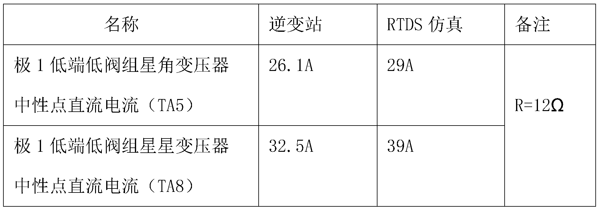
由上表可知,根据现场数据,在极1低端提供1000A直流电流、极1高端阀组处于闭锁状态,但极1高端阀组的交流断路器处于闭合状态下所提供与现场基本相同的直流电流,所需要的偏磁电阻的电阻数值为12Ω。
以上实施例仅用于帮助理解本发明的核心思想,不能以此限制本发明,对于本领域的技术人员,凡是依据本发明的思想,对本发明进行修改或者等同替换,在具体实施方式及应用范围上所做的任何改动,均应包含在本发明的保护范围之内。
Claims (3)
- 一种用于模拟换流变压器直流偏磁的测试系统,其特征在于:包括用于模拟换流变压器直流偏磁运行工况的直流输电系统RTDS仿真系统,所述RTDS仿真系统与RTDS实时数字仿真器和换流变压器保护装置连接;该RTDS仿真系统为每级由两个12脉动换流器串联构成的单级或双极直流输电系统,对应的两个12脉动换流器分别构成每个级的高端阀组和低端阀组,单级和/或双极低端阀组的星星换流变压器中性点与直流接地极之间串联有一个偏磁电阻。
- 根据权利要求1所述的用于模拟换流变压器直流偏磁的测试系统,其特征在于:所述RTDS仿真系统分别通过接口板卡和功率放大器与换流变压器保护装置连接用于提供其所需的电压、电流信号以及分接头档位的状态量信号,换流变压器保护装置将保护跳闸和告警信号反馈输入到RTDS仿真系统。
- 根据权利要求1所述的用于模拟换流变压器直流偏磁的测试系统,其特征在于,所述偏磁电阻的取值通过实测数据拟合确定:在直流输电系统单极大地运行时,不同输送功率情况下,流过换流变压器的实际直流电流,对电阻值进行拟合,使其能反映实际直流输电系统中直流电流的实际分布。
Applications Claiming Priority (2)
| Application Number | Priority Date | Filing Date | Title |
|---|---|---|---|
| CN201410299589.XA CN104360179A (zh) | 2014-06-26 | 2014-06-26 | 一种用于模拟换流变压器直流偏磁的测试系统 |
| CN201410299589.X | 2014-06-26 |
Publications (1)
| Publication Number | Publication Date |
|---|---|
| WO2015196747A1 true WO2015196747A1 (zh) | 2015-12-30 |
Family
ID=52527461
Family Applications (1)
| Application Number | Title | Priority Date | Filing Date |
|---|---|---|---|
| PCT/CN2014/093376 Ceased WO2015196747A1 (zh) | 2014-06-26 | 2014-12-09 | 一种用于模拟换流变压器直流偏磁的测试系统 |
Country Status (2)
| Country | Link |
|---|---|
| CN (1) | CN104360179A (zh) |
| WO (1) | WO2015196747A1 (zh) |
Cited By (15)
| Publication number | Priority date | Publication date | Assignee | Title |
|---|---|---|---|---|
| CN107102567A (zh) * | 2017-06-12 | 2017-08-29 | 南方电网科学研究院有限责任公司 | 一种仿真测试系统和测试方法 |
| CN108169606A (zh) * | 2018-03-12 | 2018-06-15 | 云南送变电工程有限公司 | 高压直流换流系统模拟带电检测成套装置及其检测方法 |
| CN108318757A (zh) * | 2018-01-23 | 2018-07-24 | 中国东方电气集团有限公司 | 基于半实物仿真的储能系统控制策略测试优化平台 |
| CN109299564A (zh) * | 2018-10-19 | 2019-02-01 | 国家电网有限公司 | 变压器偏磁电流仿真计算过程中温度因素影响的修正方法 |
| CN109697327A (zh) * | 2018-12-29 | 2019-04-30 | 合肥工业大学 | 特高压直流输电系统中换流单元的可靠性及灵敏度分析方法 |
| CN110445134A (zh) * | 2019-07-29 | 2019-11-12 | 南京南瑞继保工程技术有限公司 | 一种柔性合环装置 |
| CN113391146A (zh) * | 2021-06-09 | 2021-09-14 | 特变电工西安柔性输配电有限公司 | 一种柔性直流换流阀功率模块的测试装置和方法 |
| CN113447734A (zh) * | 2020-03-25 | 2021-09-28 | 许继集团有限公司 | 一种直流偏磁注流试验装置 |
| CN113675820A (zh) * | 2021-07-16 | 2021-11-19 | 国网浙江省电力有限公司杭州供电公司 | 一种用于应对变压器直流偏磁的应急控制方法 |
| CN113821928A (zh) * | 2021-09-24 | 2021-12-21 | 国网宁夏电力有限公司电力科学研究院 | 建立可视化推演模型的方法、系统、终端及存储介质 |
| CN114094548A (zh) * | 2021-11-18 | 2022-02-25 | 广东电网有限责任公司 | 过压保护测试方法、装置及柔直背靠背输电系统 |
| CN114785724A (zh) * | 2022-04-14 | 2022-07-22 | 云南电网有限责任公司电力科学研究院 | 一种远程测试系统 |
| CN114970259A (zh) * | 2022-05-20 | 2022-08-30 | 中国南方电网有限责任公司超高压输电公司广州局 | 换流变压器建模方法、装置、设备、存储介质和程序产品 |
| CN115389851A (zh) * | 2022-09-20 | 2022-11-25 | 中国南方电网有限责任公司 | 换流变压器测试方法、装置、设备及可读存储介质 |
| CN117388780A (zh) * | 2023-12-11 | 2024-01-12 | 国网江西省电力有限公司电力科学研究院 | 一种基于多元模型的变压器宽域直流偏磁测试方法及装置 |
Families Citing this family (4)
| Publication number | Priority date | Publication date | Assignee | Title |
|---|---|---|---|---|
| CN105467241B (zh) * | 2015-12-08 | 2018-04-13 | 国家电网公司 | 一种分布式换流变压器直流偏磁检测系统及其检测方法 |
| CN108008641B (zh) * | 2017-11-27 | 2021-02-05 | 华北电力科学研究院有限责任公司 | 发电机变压器组保护装置性能检测系统及方法 |
| CN113589088B (zh) * | 2021-08-27 | 2023-05-30 | 广东电网有限责任公司 | 一种柔性直流输电系统谐波抑制作用确定方法和装置 |
| CN114647227B (zh) * | 2022-02-11 | 2025-07-25 | 国网宁夏电力有限公司超高压公司 | 一种高压直流输电阀控系统全闭环试验平台和方法 |
Citations (5)
| Publication number | Priority date | Publication date | Assignee | Title |
|---|---|---|---|---|
| CN101915882A (zh) * | 2010-08-13 | 2010-12-15 | 中国南方电网有限责任公司电网技术研究中心 | 输电系统换流变压器保护装置进行闭环试验的系统及方法 |
| CN102129000A (zh) * | 2010-12-31 | 2011-07-20 | 中国南方电网有限责任公司电网技术研究中心 | 换流变压器保护rtds实时数字闭环试验系统及其方法 |
| CN202503433U (zh) * | 2012-03-25 | 2012-10-24 | 上海市电力公司 | 一种电阻器保护装置 |
| CN202503278U (zh) * | 2012-03-25 | 2012-10-24 | 上海市电力公司 | 换流变压器中性点补偿直流电流装置 |
| CN103577633A (zh) * | 2013-10-18 | 2014-02-12 | 国家电网公司 | 一种基于地电位升高的变压器直流偏磁模拟及抑制方法 |
Family Cites Families (1)
| Publication number | Priority date | Publication date | Assignee | Title |
|---|---|---|---|---|
| CN204228838U (zh) * | 2014-06-26 | 2015-03-25 | 国家电网公司 | 用于模拟换流变压器直流偏磁的测试系统 |
-
2014
- 2014-06-26 CN CN201410299589.XA patent/CN104360179A/zh active Pending
- 2014-12-09 WO PCT/CN2014/093376 patent/WO2015196747A1/zh not_active Ceased
Patent Citations (5)
| Publication number | Priority date | Publication date | Assignee | Title |
|---|---|---|---|---|
| CN101915882A (zh) * | 2010-08-13 | 2010-12-15 | 中国南方电网有限责任公司电网技术研究中心 | 输电系统换流变压器保护装置进行闭环试验的系统及方法 |
| CN102129000A (zh) * | 2010-12-31 | 2011-07-20 | 中国南方电网有限责任公司电网技术研究中心 | 换流变压器保护rtds实时数字闭环试验系统及其方法 |
| CN202503433U (zh) * | 2012-03-25 | 2012-10-24 | 上海市电力公司 | 一种电阻器保护装置 |
| CN202503278U (zh) * | 2012-03-25 | 2012-10-24 | 上海市电力公司 | 换流变压器中性点补偿直流电流装置 |
| CN103577633A (zh) * | 2013-10-18 | 2014-02-12 | 国家电网公司 | 一种基于地电位升高的变压器直流偏磁模拟及抑制方法 |
Cited By (26)
| Publication number | Priority date | Publication date | Assignee | Title |
|---|---|---|---|---|
| CN107102567A (zh) * | 2017-06-12 | 2017-08-29 | 南方电网科学研究院有限责任公司 | 一种仿真测试系统和测试方法 |
| CN107102567B (zh) * | 2017-06-12 | 2023-03-17 | 南方电网科学研究院有限责任公司 | 一种仿真测试系统和测试方法 |
| CN108318757A (zh) * | 2018-01-23 | 2018-07-24 | 中国东方电气集团有限公司 | 基于半实物仿真的储能系统控制策略测试优化平台 |
| CN108169606A (zh) * | 2018-03-12 | 2018-06-15 | 云南送变电工程有限公司 | 高压直流换流系统模拟带电检测成套装置及其检测方法 |
| CN109299564A (zh) * | 2018-10-19 | 2019-02-01 | 国家电网有限公司 | 变压器偏磁电流仿真计算过程中温度因素影响的修正方法 |
| CN109299564B (zh) * | 2018-10-19 | 2023-04-07 | 国家电网有限公司 | 变压器偏磁电流仿真计算过程中温度因素影响的修正方法 |
| CN109697327A (zh) * | 2018-12-29 | 2019-04-30 | 合肥工业大学 | 特高压直流输电系统中换流单元的可靠性及灵敏度分析方法 |
| CN109697327B (zh) * | 2018-12-29 | 2022-09-20 | 合肥工业大学 | 特高压直流输电系统中换流单元的可靠性及灵敏度分析方法 |
| CN110445134A (zh) * | 2019-07-29 | 2019-11-12 | 南京南瑞继保工程技术有限公司 | 一种柔性合环装置 |
| CN113447734A (zh) * | 2020-03-25 | 2021-09-28 | 许继集团有限公司 | 一种直流偏磁注流试验装置 |
| CN113447734B (zh) * | 2020-03-25 | 2024-04-12 | 许继集团有限公司 | 一种直流偏磁注流试验装置 |
| CN113391146A (zh) * | 2021-06-09 | 2021-09-14 | 特变电工西安柔性输配电有限公司 | 一种柔性直流换流阀功率模块的测试装置和方法 |
| CN113391146B (zh) * | 2021-06-09 | 2024-03-12 | 特变电工西安柔性输配电有限公司 | 一种柔性直流换流阀功率模块的测试装置和方法 |
| CN113675820A (zh) * | 2021-07-16 | 2021-11-19 | 国网浙江省电力有限公司杭州供电公司 | 一种用于应对变压器直流偏磁的应急控制方法 |
| CN113675820B (zh) * | 2021-07-16 | 2024-02-13 | 国网浙江省电力有限公司杭州供电公司 | 一种用于应对变压器直流偏磁的应急控制方法 |
| CN113821928A (zh) * | 2021-09-24 | 2021-12-21 | 国网宁夏电力有限公司电力科学研究院 | 建立可视化推演模型的方法、系统、终端及存储介质 |
| CN113821928B (zh) * | 2021-09-24 | 2024-01-02 | 国网宁夏电力有限公司电力科学研究院 | 建立可视化推演模型的方法、系统、终端及存储介质 |
| CN114094548A (zh) * | 2021-11-18 | 2022-02-25 | 广东电网有限责任公司 | 过压保护测试方法、装置及柔直背靠背输电系统 |
| CN114785724A (zh) * | 2022-04-14 | 2022-07-22 | 云南电网有限责任公司电力科学研究院 | 一种远程测试系统 |
| CN114785724B (zh) * | 2022-04-14 | 2024-03-19 | 云南电网有限责任公司电力科学研究院 | 一种远程测试系统 |
| CN114970259A (zh) * | 2022-05-20 | 2022-08-30 | 中国南方电网有限责任公司超高压输电公司广州局 | 换流变压器建模方法、装置、设备、存储介质和程序产品 |
| CN114970259B (zh) * | 2022-05-20 | 2024-05-31 | 中国南方电网有限责任公司超高压输电公司广州局 | 换流变压器建模方法、装置、设备、存储介质和程序产品 |
| CN115389851A (zh) * | 2022-09-20 | 2022-11-25 | 中国南方电网有限责任公司 | 换流变压器测试方法、装置、设备及可读存储介质 |
| CN115389851B (zh) * | 2022-09-20 | 2025-01-21 | 中国南方电网有限责任公司 | 换流变压器测试方法、装置、设备及可读存储介质 |
| CN117388780A (zh) * | 2023-12-11 | 2024-01-12 | 国网江西省电力有限公司电力科学研究院 | 一种基于多元模型的变压器宽域直流偏磁测试方法及装置 |
| CN117388780B (zh) * | 2023-12-11 | 2024-05-14 | 国网江西省电力有限公司电力科学研究院 | 一种基于多元模型的变压器宽域直流偏磁测试方法及装置 |
Also Published As
| Publication number | Publication date |
|---|---|
| CN104360179A (zh) | 2015-02-18 |
Similar Documents
| Publication | Publication Date | Title |
|---|---|---|
| WO2015196747A1 (zh) | 一种用于模拟换流变压器直流偏磁的测试系统 | |
| CN206208997U (zh) | 一种变电站一次通流设备 | |
| CN104749484B (zh) | 漏电监测装置 | |
| CN105870894A (zh) | 基于合闸电压幅值控制的变压器励磁涌流抑制系统及方法 | |
| CN204228838U (zh) | 用于模拟换流变压器直流偏磁的测试系统 | |
| CN104007377B (zh) | 一种直流输电换流阀用阻尼电容器防爆特性测试电路及方法 | |
| CN203983974U (zh) | 适用于试验变压器频繁空载投入的励磁涌流抑制装置 | |
| CN103296918B (zh) | 一种在低压直流电源上施加瞬间干扰信号的产生电路 | |
| CN205725459U (zh) | 一种自适应开关电源均流电路 | |
| CN203398784U (zh) | 电池充电电路的反接保护电路 | |
| CN106100332A (zh) | 一种自适应开关电源均流电路 | |
| CN204515063U (zh) | 漏电监测装置 | |
| CN103258076B (zh) | 一种整流器最小触发角限幅器仿真装置 | |
| CN203133500U (zh) | 一种逆变器最大触发角控制仿真装置 | |
| CN203101861U (zh) | 一种熄弧角启动控制仿真装置 | |
| CN103257576B (zh) | 一种熄弧角启动控制仿真装置 | |
| CN203826924U (zh) | 三相欠压脱扣器 | |
| CN203825051U (zh) | 一种新型电力网络测试信号发生装置 | |
| CN203180519U (zh) | 一种20kV电网中性点切换接地成套装置 | |
| CN105445571B (zh) | 基于动态模拟的直流偏磁对变压器保护影响的检测方法 | |
| CN204374366U (zh) | 带电压偏差补偿功能的绝缘监测装置 | |
| CN204993070U (zh) | 一种可实现欠压保护的开关电源 | |
| CN204142822U (zh) | 一种测量变压器中性点直流电流的传感器 | |
| CN103257288B (zh) | 一种直流低压保护仿真装置 | |
| CN103257581B (zh) | 一种换相失败保护仿真装置 |
Legal Events
| Date | Code | Title | Description |
|---|---|---|---|
| 121 | Ep: the epo has been informed by wipo that ep was designated in this application |
Ref document number: 14896177 Country of ref document: EP Kind code of ref document: A1 |
|
| NENP | Non-entry into the national phase |
Ref country code: DE |
|
| 122 | Ep: pct application non-entry in european phase |
Ref document number: 14896177 Country of ref document: EP Kind code of ref document: A1 |