WO2015194665A1 - 歪みセンサ及びその製造方法 - Google Patents
歪みセンサ及びその製造方法 Download PDFInfo
- Publication number
- WO2015194665A1 WO2015194665A1 PCT/JP2015/067758 JP2015067758W WO2015194665A1 WO 2015194665 A1 WO2015194665 A1 WO 2015194665A1 JP 2015067758 W JP2015067758 W JP 2015067758W WO 2015194665 A1 WO2015194665 A1 WO 2015194665A1
- Authority
- WO
- WIPO (PCT)
- Prior art keywords
- conductive fiber
- fiber material
- strain sensor
- elastomer sheet
- adhesive layer
- Prior art date
- Legal status (The legal status is an assumption and is not a legal conclusion. Google has not performed a legal analysis and makes no representation as to the accuracy of the status listed.)
- Ceased
Links
Images




Classifications
-
- G—PHYSICS
- G01—MEASURING; TESTING
- G01B—MEASURING LENGTH, THICKNESS OR SIMILAR LINEAR DIMENSIONS; MEASURING ANGLES; MEASURING AREAS; MEASURING IRREGULARITIES OF SURFACES OR CONTOURS
- G01B7/00—Measuring arrangements characterised by the use of electric or magnetic techniques
- G01B7/16—Measuring arrangements characterised by the use of electric or magnetic techniques for measuring the deformation in a solid, e.g. by resistance strain gauge
Definitions
- the present invention relates to a strain sensor that detects bending and expansion / contraction of a specific part, and more particularly, to a strain sensor that can operate without a power source by using an RFID element and a method for manufacturing the same.
- Patent Document 1 a sheet-like bending sensor that expands and contracts is disposed on a glove, and the bending sensor detects the movement of the wearer's finger, and processing means and communication means Is output to the outside through the device and processed as a movement of the wearer's hand.
- this sheet-like bending sensor the use of carbon nanotube fibers is exemplified.
- an object of the present invention is to use an RFID element whose cost has been reduced with the spread of IC cards in recent years and a flexible conductor whose resistance value changes according to bending and expansion / contraction as its antenna. It can be applied to various applications such as expansion / contraction of machine parts, bending of flat and curved surfaces, etc., realizing a low-cost, compact, lightweight, excellent wearability, and power supply-free strain sensor There is to do.
- the strain sensor of the present invention is electrically connected to an elastomer sheet having a pressure-sensitive adhesive layer formed on the surface thereof, an RFID element attached to the pressure-sensitive adhesive layer, and an antenna terminal formed on the RFID element.
- electrical detachment between the conductive fiber materials is performed according to the degree of bending of the elastomer sheet starting from the RFID element.
- a flexible antenna that changes the resistance value.
- the strain detection system using the strain sensor irradiates the RFID element with a radio wave and receives a radio wave returned from the RFID element and a signal output intensity returned from the RFID element. And calculating a resistance value of the flexible antenna, and calculating means for calculating a bending degree of the elastomer sheet based on the calculated resistance value of the flexible antenna.
- the strain sensor manufacturing method of the present invention includes a step of attaching an RFID element to an adhesive sheet formed on the surface of an elastomer sheet, and an electrical connection to antenna terminals formed at both ends of the RFID element, respectively. It comprised from the process of sticking a conductive fiber material to a longitudinal direction, and the process of removing the conductive fiber material which could not be apply
- FIG. 1 is a schematic diagram of a strain sensor according to the present invention.
- FIG. 2A is a diagram schematically illustrating an initial state of the conductive fiber material.
- FIG. 2B is a diagram schematically illustrating an initial bending state of the conductive fiber material.
- FIG. 2C is a diagram schematically illustrating a bent state of the conductive fiber material.
- FIG. 3 is a diagram showing the relationship between the elongation of the elastomer sheet and the increase in resistance value.
- FIG. 4 is a diagram showing the relationship between the length of the silver-coated fiber, the elongation of the stretched elastomer sheet, and the increase in resistance.
- FIG. 5 is a diagram illustrating an operating environment of the strain sensor.
- FIG. 5 is a diagram illustrating an operating environment of the strain sensor.
- FIG. 6 is a diagram showing components of resistance change of the flexible antenna.
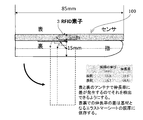
- FIG. 7 is a diagram illustrating a configuration of the first embodiment (finger bending sensor).
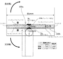
- FIG. 8 is a diagram illustrating a configuration of the second embodiment (link bending sensor).
- FIG. 9 is a diagram showing a configuration of Example 3 (a bending sensor attached to a knee supporter).
- FIG. 10 is a diagram showing a process for manufacturing the strain sensor of the present invention.
- FIG. 1 shows a schematic diagram of a strain sensor 100 according to the present invention.
- An adhesive layer 1a is formed on the surface of the elastomer sheet 1, and a conductive fiber material 2 such as silver-coated nylon fiber having a predetermined length and thickness is placed on the left and right sides in a band-like region with a central gap therebetween. It is stuck.
- An IC chip-like RFID element 3 is stuck in the gap between the adhesive layers 1a, and the lower surface of the conductive fiber material 2 is electrically contacted with the metal wiring 4 connecting the antenna terminals.
- a cover elastomer sheet 5 having an adhesive layer.
- the metal wiring 4 is kept pressed against the conductive fiber material 2, and when the elastomer sheet 1 is bent or stretched, the metal wiring 4 is in electrical contact with the metal wiring 4. You can slide while maintaining.
- a concave portion is formed on the lower surface of the cover elastomer sheet 5 corresponding to the region of the conductive fiber material 2 so that the upper surface of the adhered conductive fiber material 2 is not restricted.
- the conductive fiber material 2 is electrically connected to each other to minimize the resistance value, and the RFID element 3 has the highest received intensity. Become.
- FIGS. 2B and 2C as the elastomer sheet 1 is bent or stretched, the electrical continuity between the conductive fiber materials 2 gradually begins to deviate, and the resistance value increases. Along with this, the reception intensity of the RFID element 3 decreases.
- FIG. 3 there is a one-to-one relationship between the amount of expansion associated with bending or expansion and the amount of increase in the resistance value of the flexible antenna.
- the lower straight line shows an ideal state where all the electrical connections of the individual conductive fiber materials 2 are maintained regardless of the stretch amount of the elastomer sheet 1, and basically, the conductive fibers accompanying the stretch.
- the resistance value of the flexible antenna increases in proportion to the distance between both ends of the material 2. That is, when the elongation amount of the elastomer sheet 1 reaches a certain value, separation between the conductive fiber materials 2 starts to occur, and the separation amount increases in accordance with the elongation.
- FIGS. 2B and 2C the state 1 From state to state 2, the resistance value of the flexible antenna gradually increases.
- the conductive circuit wiring of the present invention was formed on an elastomer sheet having a sample size of 48 mm ⁇ 2 mm using silver-coated fibers (diameter: 17.6 ⁇ m) obtained by coating nylon with silver as the conductive fiber material 2.
- FIG. 4 shows the length of the silver-coated fiber and the measured value of the change in resistance value associated with the extension during bending.
- the term “sealed” means that the silver-coated fibers attached to the adhesive layer have the same or more flexibility than the similar elastomer sheet (e.g., the above-described cover elastomer sheet 5) or the elastomer sheet 1.
- An embodiment is shown in which the surface of the silver-coated fiber (conductive fiber material 2) sealed with a coating layer made of a thin film or the like and stuck to the adhesive layer 1a is pressed down.
- the relationship between the material of the conductive fiber material, the length, the diameter, the arrangement in the adhesive layer, and the resistance increasing characteristic as shown in FIG. 4 will be considered.
- (1) Material of conductive fiber material As described above, the conductive fiber material should move relatively while maintaining the intersection with other conductive fiber materials on the surface of the adhesive layer. Therefore, even when the flexible antenna is bent greatly, it is preferable that the electrical connection between the conductive fiber materials is continuously changed. Thus, when a large bend is expected, for example, a silver-coated fiber in which the surface of a nylon fiber is coated with silver can be cited as a suitable example.
- a fiber material obtained by polymerizing a polypyrrole-based conductive polymer on the fiber surface and integrated with the base fiber also has a thin conductive polymer layer on the surface of 0.01 to 0.05 ⁇ m, which may impair the properties of the fiber material. Suitable as a non-conductive fiber material.
- a metal short fiber obtained by cutting a thin wire of copper or aluminum into a predetermined length can be used as the conductive fiber material. .
- Diameter of the conductive fiber material Increasing the diameter of the conductive fiber material can reduce the electrical resistance per piece, but the rigidity increases and the electrical contact with other adjacent conductive fiber materials is smooth. Not done.
- the electrical resistance is determined by the surface area of the conductive fiber material. Therefore, it is not always possible to obtain the desired electrical resistance with respect to the total amount of the conductive fiber material adhered, so the characteristics of the conductive fiber material used and the change in electrical resistance due to bending of the elastomer sheet Considering the rate, etc., an optimum diameter is selected so that a large resistance value change can be obtained.
- a brush roller method or a spray method can be employed.
- a mask corresponding to a flexible antenna is placed on an elastomer sheet 1 having an adhesive layer on the surface, an adhesive is applied to form an adhesive layer, and then the conductive fiber material 2 is formed by a rotating brush. It is embedded in this adhesive layer. Thereby, a certain degree of orientation can be given to the conductive fiber material 2. Even when the elastomer sheet 1 is greatly expanded and contracted in the longitudinal direction, the electrical contact between the conductive fiber materials 2 can be maintained.
- the conductive fiber material 2 that intersects the width direction is insufficient on the surface of the adhesive layer, which causes a sudden change in the change characteristic of the conductive resistance.
- a mask made of a highly peelable material is placed on the elastomer sheet 1 having a curable adhesive layer formed on the entire surface, and the conductive fiber material 2 is embedded in the adhesive layer with a rotating brush. You may make it peel from a layer.
- the spray method sprays the conductive fiber material 2 onto the adhesive layer at high pressure by spraying from above the mask corresponding to the flexible antenna, and a random arrangement can be obtained.
- the conductive fiber material 2 is supplied to the adhesive layer until it exceeds a saturated state where the conductive fiber material 2 can be attached to the adhesive layer, and the excess conductive fiber material 2 is removed using compressed air or the like.
- the length of the flexible antenna can be determined by the length of the adhesive layer 1a of the elastomer sheet 1 in which the conductive fiber material 2 is embedded.
- FIG. 5 shows the operating environment of the strain sensor.
- the reader / writer 6 outputs a radio wave of maximum 4 W (local radio station) defined by the Radio Law, and this radio wave is received by the RFID element 3 via the flexible antenna of the strain sensor 100.
- the RFID element 3 returns a response radio wave having a strength corresponding to the reception sensitivity of the flexible antenna to the reader / writer 6 in addition to the distance to the reader / writer 6 and the radio wave environment.
- the intensity of the response radio wave is about several mW at the maximum and includes the ID information of the RFID element 3.
- the strain sensor 100 outputs a response radio wave corresponding to the degree of bending, and the reader / writer 6 can detect the reception sensitivity of the flexible antenna according to the strength by receiving the response radio wave.
- the change in the reception sensitivity is mainly due to the change in the resistance value of the flexible antenna. Therefore, the amount of increase in the resistance value of the flexible antenna is calculated based on the decrease in the reception sensitivity with respect to the reception sensitivity without bending using a data map or the like, and the bending degree of the flexible antenna is obtained from the relationship shown in FIG. be able to.
- the flexible antenna may be separated from the reader / writer 6 or may be behind the person and the reception sensitivity may change.
- the change in the signal strength due to the movement of the entire body is small compared to the change in the signal strength due to the resistance value change due to the bending of the flexible antenna.
- a plurality of reader / writers 6 may be arranged on the circumference with respect to the strain sensor, and the detection value of the reader / writer 6 having the highest reception sensitivity may be selected.
- the strain sensor of the present invention is applied to a sensor for detecting the bending of a finger.
- the RFID element 3 of the strain sensor is disposed immediately above the second joint of the finger, and is attached so as not to be displaced along the surface of the finger along the longitudinal direction of the finger.
- the sensor may be attached to the surface of the finger with an adhesive, but the sensor is mounted inside the finger sac and attached to the finger with the top and bottom aligned, or fixed with a band. You may do it.
- the strain sensor when the strain sensor is irradiated with a radio wave, the radio wave is received with a reception intensity corresponding to the bending angle of the finger, and an output corresponding to this is performed.
- the total length of the strain sensor 100 extending from the RFID element 3 in both the left and right directions is 85 mm
- the thickness of the second joint of the finger is 15 mm
- the thickness of the flexible sheet is 5 mm. It is assumed that the second joint is bent by 90 °.
- the expansion rate increases from 0% to 18.5%, and accordingly, the resistance value of the flexible antenna increases. Therefore, a distortion detection system using a microcomputer or the like is used to calculate how much the reception sensitivity of the reader / writer 6 is reduced when the finger is bent by 90 °, based on the initial reception sensitivity when the finger is straightened. To do. Thereby, the amount of increase in the resistance value of the flexible antenna can be calculated, and the bending degree of the flexible antenna, that is, the flexible sheet can be obtained from the relationship shown in FIG.
- Example 2 As shown in FIG. 8, when one link L1 can rotate in the positive direction (clockwise) and the negative direction (counterclockwise) with respect to the other link L2 along the plane of the paper, the rotation It is necessary to determine whether the angle is positive or negative.
- the strain sensors 100a and 100b are mounted on both surfaces of the links L1 and L2 so that the RFID elements 3a and 3b of the strain sensors are above and below the rotary joint portion J.
- the detection of the degree of bending by each of the strain sensors 100a and 100b is the same as in the first embodiment.
- the links L1 and L2 have a thickness of 15 mm, the total length of the strain sensors is 85 mm, and the thickness is 5 mm,
- the rotation angle is 90 °
- the actual elongation of the front-side strain sensor 100a is 15.7 mm
- the expansion rate is 18.5%
- the actual elongation of the back-side strain sensor 100b is 11.8 mm
- the expansion rate is 13.9. %.
- the direction of rotation and the angle of rotation can be calculated by selecting the one with the larger elongation and expansion rate based on the ID transmitted from the RFID elements 3a and 3b of the strain sensors 100a and 100b.
- a plurality of strain sensors are attached in the vertical and circumferential directions of the knee supporter, and the contraction of each muscle is detected together with the knee flexion angle.
- the knee supporter 200 has strain sensors of ID: 5 to ID: 7 in the vertical direction, and ID: 1 to ID: 4 (from the front side of the knee in the circumferential direction from the top). ), ID: 8 to ID: 11 (knee rear side).
- ID: 5 to ID: 7 in the vertical direction
- ID: 1 to ID: 4 from the front side of the knee in the circumferential direction from the top.
- ID: 8 to ID: 11 knee rear side
- the same number of strain sensors are attached in the vertical direction on the back side of ID: 5 to ID: 7.
- each of the reader / writers 6-1 to 6-4 transmits a radio wave of its own frequency, and all the strain sensors A reply radio wave is received together with the ID.
- the intensity of the return radio wave received from each strain sensor differs depending on the movement of the body, etc., so that four reader / writers 6-1 to 6-
- a strain detection system comprising a microcomputer or the like.
- FIG. 10 shows a manufacturing procedure of the strain sensor used in the first embodiment.
- Step 1 A resin cover sheet is attached to the surface of the adhesive elastomer sheet, and the resin cover sheet is cut out by laser processing so as to correspond to two conductive fiber material application regions.
- Step 2 The cut-out resin cover sheet is peeled off to expose the adhesive layer.
- Step 3 By the brush roller method or the spray method, the conductive fiber material is stuck to the exposed adhesive layer until it becomes saturated.
- Step 4) A portion of the resin cover sheet corresponding to the gap formed between the two conductive fiber material attachment regions is peeled off, and an IC chip as an RFID element is mounted on the exposed adhesive layer.
- the metal wiring which connects between antenna terminals is arrange
- Concave portions are formed on the back surface of the cover elastomer sheet by laser processing so as to correspond between the conductive fiber material application regions.
- Step 6 Using the adhesive layer remaining on the adhesive elastomer sheet or the adhesive layer on the back surface of the cover elastomer sheet, the surface of the adhesive elastomer sheet is sealed with the cover elastomer sheet.
- Example 2 For the strain sensor used in Example 2, an elastomer sheet having an adhesive layer on both sides is used, and after Step 6, the elastomer sheet is inverted and the process from Step 1 is repeated.
- the above manufacturing method is based on the premise that strain sensors are manufactured one by one. However, when a plurality of strain sensors are arranged on a plane as in Example 3, an elastomer sheet having a large area is used. Then, in Step 1 described above, a conductive fiber material attachment region corresponding to each of the plurality of strain sensors is formed, and Steps 2 to 6 may be repeated for each strain sensor. At that time, when an elastomer sheet having the same area is used as the cover elastomer sheet, in step 5, a recess is formed corresponding to each strain sensor, but the cover elastomer sheet divided for each strain sensor is used. May be.
- an RFID element that has been reduced in cost with the spread of IC cards and a flexible conductor whose resistance value changes according to bending and expansion / contraction as its antenna are used. It can be applied to various uses such as not only bending but also expanding / contracting machine parts and bending a plane.
- a strain sensor that is low cost, small and light, has excellent wearability, and does not require a power source, it can be expected to be widely used in fields such as sports science, robots, and man-machine interfaces.
- Elastomer sheet 1a Adhesive layer 2: Conductive fiber material 3: RFID element 4: Metal wiring 5: Elastomer sheet for cover 6: Reader / writer 100: Strain sensor 200: Knee supporter
Landscapes
- Physics & Mathematics (AREA)
- General Physics & Mathematics (AREA)
- Measurement Of Length, Angles, Or The Like Using Electric Or Magnetic Means (AREA)
Abstract
歪みセンサ100は、表面に粘着層が形成されたエラストマーシート1と、この粘着層に貼着されたRFID素子3と、RFID素子3のアンテナ端子と電気的に接続され、粘着層に沿って、互いに電気的に接触するよう貼着された導電性繊維材料2とからなる。導電性繊維材料2により構成されるフレキシブルアンテナは、RFID素子3を起点としたエラストマーシート1の屈曲の程度に応じて、導電性繊維材料2間で電気的離脱を発生させ、抵抗値を変化させる。RFID素子3からの送信出力に基づいて算出したフレキシブルアンテナの抵抗値により、ラストマーシート1の屈曲度を演算する。このように、RFID素子を利用することで、電源不要、小型軽量、低コストで、伸縮性、屈曲性、耐久性に優れ、しかも、装着性に優れた歪みセンサを実現する。
Description
本発明は、特定部位の屈曲や伸縮を検出する歪みセンサ、特に、RFID素子を利用することで、無電源で作動可能な歪みセンサ及びその製造方法に関する。
本技術分野の背景技術として、下記の特許文献1が知られており、伸縮するシート状の屈曲センサを手袋に配置し、装着者の指の動きを屈曲センサが検出し、処理手段、通信手段を介して外部に出力し、装着者の手の動きとして処理することが記載されている。このシート状の屈曲センサとして、カーボンナノチューブ繊維を用いることが例示されている。
しかし、特許文献1のものでは、シート状の屈曲センサに加え、処理手段、通信手段、さらには、これらへ電力供給するための電源が必要となり、高価なものとなる。しかも、これらが手袋内に取り付けられているため、装着者に違和感を与えるばかりでなく、自由な手の動きが阻害されてしまう。
そこで、本発明の目的は、近年、ICカードの普及に伴い低コスト化されたRFID素子と、そのアンテナとして、屈曲や伸縮に応じて抵抗値の変化するフレキシブル導電体を利用することで、指の屈曲のみならず、機械部品の伸縮、さらには平面や曲面の屈曲など、様々な用途に適用することができ、低コスト、小型軽量で装着性に優れ、しかも、電源不要の歪みセンサを実現することにある。
そこで、本発明の目的は、近年、ICカードの普及に伴い低コスト化されたRFID素子と、そのアンテナとして、屈曲や伸縮に応じて抵抗値の変化するフレキシブル導電体を利用することで、指の屈曲のみならず、機械部品の伸縮、さらには平面や曲面の屈曲など、様々な用途に適用することができ、低コスト、小型軽量で装着性に優れ、しかも、電源不要の歪みセンサを実現することにある。
本発明の歪みセンサは、表面に粘着層が形成されたエラストマーシートと、前記粘着層に貼着されたRFID素子と、前記RFID素子に形成したアンテナ端子と電気的に接続され、前記粘着層に沿って、互いに電気的に接触するよう貼着された導電性繊維材料からなり、前記RFID素子を起点とした前記エラストマーシートの屈曲の程度に応じて、前記導電性繊維材料間で電気的離脱を発生させ、抵抗値を変化させるフレキシブルアンテナとを備えている。
この歪みセンサを用いた歪み検出システムは、前記RFID素子に電波を照射するとともに、前記RFID素子から返信される電波を受信するリーダーライターと、前記RFID素子から返信される信号出力の強度に応じて、前記フレキシブルアンテナの抵抗値を算出するとともに、算出した前記フレキシブルアンテナの抵抗値に基づいて、前記エラストマーシートの屈曲度を演算する演算手段とを備えている、
この歪みセンサを用いた歪み検出システムは、前記RFID素子に電波を照射するとともに、前記RFID素子から返信される電波を受信するリーダーライターと、前記RFID素子から返信される信号出力の強度に応じて、前記フレキシブルアンテナの抵抗値を算出するとともに、算出した前記フレキシブルアンテナの抵抗値に基づいて、前記エラストマーシートの屈曲度を演算する演算手段とを備えている、
また、本発明の歪みセンサの製造方法は、エラストマーシートの表面に形成した粘着シートにRFID素子を貼着する工程と、前記RFID素子の両端に形成したアンテナ端子に電気的に接続するよう、それぞれ長手方向に導電性繊維材料を貼着させる工程と、前記導電性繊維材料のうち、前記粘着層に塗布できなかった導電性繊維材料を除去する工程とから構成した。
本発明によれば、低コスト、小型軽量で装着性に優れ、電源不要の歪みセンサを実現することができる。
指の屈曲センサを例に、本発明の基本原理について説明する。
図1に、本発明に基づく歪みセンサ100の概要図を示す。
エラストマーシート1の表面に粘着層1aが形成されており、中央の空隙を挟んで、帯状の領域に、所定の長さ、太さを有する銀被覆ナイロン繊維などの導電性繊維材料2が左右に貼着されている。
粘着層1a間の空隙には、ICチップ状のRFID素子3が貼着され、そのアンテナ端子間を接続する金属配線4を、導電性繊維材料2上に電気的に接触させた状態で、下面に粘着層を備えたカバー用エラストマーシート5により被覆されている。
図1に、本発明に基づく歪みセンサ100の概要図を示す。
エラストマーシート1の表面に粘着層1aが形成されており、中央の空隙を挟んで、帯状の領域に、所定の長さ、太さを有する銀被覆ナイロン繊維などの導電性繊維材料2が左右に貼着されている。
粘着層1a間の空隙には、ICチップ状のRFID素子3が貼着され、そのアンテナ端子間を接続する金属配線4を、導電性繊維材料2上に電気的に接触させた状態で、下面に粘着層を備えたカバー用エラストマーシート5により被覆されている。
このように、サンドイッチ状に積層することで、金属配線4は、導電性繊維材料2に押え付けられた状態を維持し、エラストマーシート1が屈曲あるいは伸張した際、金属配線4との電気接触を維持しながらスライドできるようになっている。
なお、カバー用エラストマーシート5の下面には、導電性繊維材料2の領域に対応して凹部が形成されており、貼着された導電性繊維材料2の上面を拘束しないようにしている。
この構成により、以下に詳述するように、エラストマーシート1の粘着層1aに貼着された導電性繊維材料2は、RFID素子3のフレキシブルアンテナとして機能する。
なお、カバー用エラストマーシート5の下面には、導電性繊維材料2の領域に対応して凹部が形成されており、貼着された導電性繊維材料2の上面を拘束しないようにしている。
この構成により、以下に詳述するように、エラストマーシート1の粘着層1aに貼着された導電性繊維材料2は、RFID素子3のフレキシブルアンテナとして機能する。
図2Aに示すように、エラストマーシート1に屈曲や伸縮がない初期状態では、導電性繊維材料2が互いに電気的に導通することで抵抗値が最小となり、RFID素子3の受信強度が最高値となる。
一方、図2B、Cに示すように、エラストマーシート1の屈曲や伸張に伴い、導電性繊維材料2間の電気的導通が次第に外れ始め、抵抗値が増大していく。これに伴い、RFID素子3の受信強度が減少していく。
一方、図2B、Cに示すように、エラストマーシート1の屈曲や伸張に伴い、導電性繊維材料2間の電気的導通が次第に外れ始め、抵抗値が増大していく。これに伴い、RFID素子3の受信強度が減少していく。
図3に示すように、屈曲あるいは伸張に伴う伸張量と、フレキシブルアンテナの抵抗値増加量は1対1の関係にある。
下側の直線が、エラストマーシート1の伸張量にかかわらず、個々の導電性繊維材料2の電気的接続がすべて維持される理想的な状態を示し、基本的には、伸張に伴う導電性繊維材料2の両端間距離に比例して、フレキシブルアンテナの抵抗値が増大する。
すなわち、エラストマーシート1の伸張量がある程度の値になると、導電性繊維材料2間の離脱が発生し始め、伸張に応じて離脱量が増大し、図2B、図2Cに示すように、状態1から状態2に遷移し、これに伴いフレキシブルアンテナの抵抗値が次第に増大していく。
下側の直線が、エラストマーシート1の伸張量にかかわらず、個々の導電性繊維材料2の電気的接続がすべて維持される理想的な状態を示し、基本的には、伸張に伴う導電性繊維材料2の両端間距離に比例して、フレキシブルアンテナの抵抗値が増大する。
すなわち、エラストマーシート1の伸張量がある程度の値になると、導電性繊維材料2間の離脱が発生し始め、伸張に応じて離脱量が増大し、図2B、図2Cに示すように、状態1から状態2に遷移し、これに伴いフレキシブルアンテナの抵抗値が次第に増大していく。
抵抗値の変化について、より詳細に説明する。
導電性繊維材料2は、粘着層1aに達した段階で、その先端部や中間部で、少なくとも一部が粘着層に埋もれた状態となる。そして、表面をローラーで軽く押圧する際、あるいは、表面をフィルム等で被覆する際に、露出する部分が粘着層1aの表面上に倒れ、互いに交差し電気的に接続された状態となる。これにより、図2Aに示す初期状態のように、エラストマーシート1の長手方向両端部全域にわたり電気的導通が確保され、アンテナとして機能する。
なお、図中、黒丸で示す箇所は導電性繊維材料2の接続点、矢印は、左上方の導電性繊維材料2を起点とした電流の流れを示す。
導電性繊維材料2は、粘着層1aに達した段階で、その先端部や中間部で、少なくとも一部が粘着層に埋もれた状態となる。そして、表面をローラーで軽く押圧する際、あるいは、表面をフィルム等で被覆する際に、露出する部分が粘着層1aの表面上に倒れ、互いに交差し電気的に接続された状態となる。これにより、図2Aに示す初期状態のように、エラストマーシート1の長手方向両端部全域にわたり電気的導通が確保され、アンテナとして機能する。
なお、図中、黒丸で示す箇所は導電性繊維材料2の接続点、矢印は、左上方の導電性繊維材料2を起点とした電流の流れを示す。
そして、エラストマーシート1が徐々に伸張していくとき、図2Bに示す状態1のように、多くの導電性繊維材料2は、粘着層表面上において、他の導電性繊維材料2との交差を維持しながら相対的に移動することで、エラストマーシート1の柔軟性に影響を及ぼすことなく、電気的な導通を維持するが、両端間距離の増大に伴い抵抗値が上昇していく。
エラストマーシート1にさらなる伸張が生じると、図2Cに示す状態2のように、導電性繊維材料2の両端間距離の増大とともに、導電性繊維材料2間の離脱し、これに伴い電気的接続が減少していき、抵抗値が増大していくことになる。
ここで、導電性繊維材料2として、ナイロンに銀被覆を施した銀被覆繊維(径;17.6μm)を用いて、サンプルサイズ48mm×2mmのエラストマーシートに本発明の導電性回路配線を形成した場合、銀被覆繊維の長さと、屈曲時の伸張に伴う抵抗値変化の実測値を図4に示す。
なお、図中、封止とあるのは、粘着層に貼付した銀被覆繊維に対し、同様のエラストマーシート(上述したカバー用エラストマーシート5等)やエラストマーシート1と同等以上の柔軟性を備えた薄膜フィルム等からなる被覆層により封止し、粘着層1aに貼付した銀被覆繊維(導電性繊維材料2)の表面を押さえ込んだ態様を示している。
なお、図中、封止とあるのは、粘着層に貼付した銀被覆繊維に対し、同様のエラストマーシート(上述したカバー用エラストマーシート5等)やエラストマーシート1と同等以上の柔軟性を備えた薄膜フィルム等からなる被覆層により封止し、粘着層1aに貼付した銀被覆繊維(導電性繊維材料2)の表面を押さえ込んだ態様を示している。
最大伸張量において、抵抗値増分が少ないものから順に、[銀被覆繊維3.0mmかつ封止あり]、[銀被覆繊維0.5mmかつ封止あり]、[銀被覆繊維3.0mmかつ封止なし]、[銀被覆繊維0.5mmと3.0mmの混在かつ封止なし]、[銀被覆繊維0.5mmかつ封止なし]をそれぞれ示している。
この実測結果から分かるように、導電性繊維材料として、径17.6μm、長さ0.5mmの銀被覆繊維を用いて、上面を封止しない場合、すなわち、[銀被覆繊維0.5mmかつ封止なし]の場合、最大伸張量25mmまでであれば、伸張率に対し、抵抗値の増大分が大きく、フレキシブルアンテナとして好ましい。
もちろん、[銀被覆繊維0.5mmと3.0mmの混在かつ封止なし]、[銀被覆繊維3.0mmかつ封止なし]も利用可能であるし、[銀被覆繊維0.5mmかつ封止あり]であれば、伸び30mmにも対応できる。
ただし、[銀被覆繊維3.0mmかつ封止あり]は、伸張率に対し、リニアな抵抗値の増大分が得られるが、増大分が小さく、フレキシブルアンテナの抵抗値変化を大きく取れないことが分かる。
この実測結果から分かるように、導電性繊維材料として、径17.6μm、長さ0.5mmの銀被覆繊維を用いて、上面を封止しない場合、すなわち、[銀被覆繊維0.5mmかつ封止なし]の場合、最大伸張量25mmまでであれば、伸張率に対し、抵抗値の増大分が大きく、フレキシブルアンテナとして好ましい。
もちろん、[銀被覆繊維0.5mmと3.0mmの混在かつ封止なし]、[銀被覆繊維3.0mmかつ封止なし]も利用可能であるし、[銀被覆繊維0.5mmかつ封止あり]であれば、伸び30mmにも対応できる。
ただし、[銀被覆繊維3.0mmかつ封止あり]は、伸張率に対し、リニアな抵抗値の増大分が得られるが、増大分が小さく、フレキシブルアンテナの抵抗値変化を大きく取れないことが分かる。
ここで、導電性繊維材料の材質、長さ、径、そして、粘着層における配列と、図4に示されるような抵抗増加特性との関係について考察する。
(1)導電性繊維材料の材質
上述のように、導電性繊維材料は、粘着層表面上において、他の導電性繊維材料との交差を維持しながら、それぞれ相対的に移動するものであることから、フレキシブルアンテナが大きく屈曲した場合でも、導電性繊維材料間の電気的接続が連続的に変化することが好ましい。
そこで、大きな屈曲が予想される場合には、例えば、ナイロン繊維の表面に銀を被覆した銀被被覆繊維等を好適例として挙げることができる。
さらに、ポリピロール系導電性ポリマーを繊維表面に重合させ、基材繊維と一体化した繊維素材も、表面の導電性ポリマー層が0.01~0.05μmと薄く、繊維素材の特性を損なうことのない導電性繊維材料として好適である。
一方、伸縮や屈曲がさほど大きくない箇所にフレキシブルアンテナを装着する場合には、例えば、銅、アルミニウムの細線を、所定の長さに切断した金属短繊維を導電性繊維材料として採用することができる。
(1)導電性繊維材料の材質
上述のように、導電性繊維材料は、粘着層表面上において、他の導電性繊維材料との交差を維持しながら、それぞれ相対的に移動するものであることから、フレキシブルアンテナが大きく屈曲した場合でも、導電性繊維材料間の電気的接続が連続的に変化することが好ましい。
そこで、大きな屈曲が予想される場合には、例えば、ナイロン繊維の表面に銀を被覆した銀被被覆繊維等を好適例として挙げることができる。
さらに、ポリピロール系導電性ポリマーを繊維表面に重合させ、基材繊維と一体化した繊維素材も、表面の導電性ポリマー層が0.01~0.05μmと薄く、繊維素材の特性を損なうことのない導電性繊維材料として好適である。
一方、伸縮や屈曲がさほど大きくない箇所にフレキシブルアンテナを装着する場合には、例えば、銅、アルミニウムの細線を、所定の長さに切断した金属短繊維を導電性繊維材料として採用することができる。
(2)導電性繊維材料の長さ
導電性繊維材料が長いほど、隣接する導電性繊維材料との交差部からの距離が長くなり、フレキシブルアンテナの伸張量が増えても、隣接する導電性繊維材料間で電気的接続が離脱しにくく、大きな抵抗値変化を得ることができない。
ただし、導電性繊維材料が短かすぎると、粘着層に接触しない部分が増大し、導電性繊維材料が粘着層から離脱しやすくなってしまうので、フレキシブルアンテナの屈曲率なども考慮して、装着する箇所で発生する伸張率に応じて、できるだけ大きな抵抗値変化が得られるよう、最適な長さ導電性繊維材料を選択する。
導電性繊維材料が長いほど、隣接する導電性繊維材料との交差部からの距離が長くなり、フレキシブルアンテナの伸張量が増えても、隣接する導電性繊維材料間で電気的接続が離脱しにくく、大きな抵抗値変化を得ることができない。
ただし、導電性繊維材料が短かすぎると、粘着層に接触しない部分が増大し、導電性繊維材料が粘着層から離脱しやすくなってしまうので、フレキシブルアンテナの屈曲率なども考慮して、装着する箇所で発生する伸張率に応じて、できるだけ大きな抵抗値変化が得られるよう、最適な長さ導電性繊維材料を選択する。
(3)導電性繊維材料の径
導電性繊維材料の径を大きくすると、一本あたりの電気抵抗を小さくできるが、剛性が増大し、隣接する他の導電性繊維材料との電気的接触がスムースに行われない。
また、後述するように、導電性繊維材料として、ナイロン等の繊維に銀などの導電性の良好な金属を被覆したものを使用する場合には、電気抵抗が、導電性繊維材料の表面積で決定されるため、貼着された導電性繊維材料の総量に対し、必ずしも所期の電気抵抗を得ることができないので、使用する導電性繊維材料の特性や、エラストマーシートの屈曲に伴う電気抵抗の変化率なども考慮して、大きな抵抗値変化が得られるよう、最適な径を選択する。
導電性繊維材料の径を大きくすると、一本あたりの電気抵抗を小さくできるが、剛性が増大し、隣接する他の導電性繊維材料との電気的接触がスムースに行われない。
また、後述するように、導電性繊維材料として、ナイロン等の繊維に銀などの導電性の良好な金属を被覆したものを使用する場合には、電気抵抗が、導電性繊維材料の表面積で決定されるため、貼着された導電性繊維材料の総量に対し、必ずしも所期の電気抵抗を得ることができないので、使用する導電性繊維材料の特性や、エラストマーシートの屈曲に伴う電気抵抗の変化率なども考慮して、大きな抵抗値変化が得られるよう、最適な径を選択する。
(4)粘着層における導電性繊維材料の配列
粘着層に導電性繊維材料を貼付する際には、ブラシローラー法やスプレー法を採用することができる。
ブラシローラー法とは、表面に粘着層を有するエラストマーシート1に、フレキシブルアンテナに対応するマスクを配置し、接着剤を塗布して粘着層を形成した後、回転ブラシにより、導電性繊維材料2をこの粘着層に埋め込むものである。
これにより、導電性繊維材料2にある程度の配向性を与えることができる。エラストマーシート1が長手方向に大きく伸縮した場合でも、導電性繊維材料2どうしの電気的接触を維持することが可能となる。
ただし、エラストマーシート1の幅方向の伸縮に対しては、粘着層の表面において、幅方向に交差する導電性繊維材料2が不足しているため、導電抵抗の変化特性に急激な変化を招く場合がある。
なお、硬化型の粘着層が全面に形成されたエラストマーシート1に、剥離性の高い素材からなるマスクを配置し、回転ブラシにより導電性繊維材料2をこの粘着層に埋め込み、その後、マスクを粘着層から剥離するようにしてもよい。
粘着層に導電性繊維材料を貼付する際には、ブラシローラー法やスプレー法を採用することができる。
ブラシローラー法とは、表面に粘着層を有するエラストマーシート1に、フレキシブルアンテナに対応するマスクを配置し、接着剤を塗布して粘着層を形成した後、回転ブラシにより、導電性繊維材料2をこの粘着層に埋め込むものである。
これにより、導電性繊維材料2にある程度の配向性を与えることができる。エラストマーシート1が長手方向に大きく伸縮した場合でも、導電性繊維材料2どうしの電気的接触を維持することが可能となる。
ただし、エラストマーシート1の幅方向の伸縮に対しては、粘着層の表面において、幅方向に交差する導電性繊維材料2が不足しているため、導電抵抗の変化特性に急激な変化を招く場合がある。
なお、硬化型の粘着層が全面に形成されたエラストマーシート1に、剥離性の高い素材からなるマスクを配置し、回転ブラシにより導電性繊維材料2をこの粘着層に埋め込み、その後、マスクを粘着層から剥離するようにしてもよい。
一方、スプレー法は、フレキシブルアンテナに対応するマスクの上方から、導電性繊維材料2を粘着層に、スプレーで高圧で吹き付けるもので、ランダムな配列を得ることができる。
いずれの場合でも、導電性繊維材料2が粘着層に貼着できる飽和状態を超えるまで、粘着層に供給し、余分な導電性繊維材料2を圧縮空気などを用いて除去することで、フレキシブルアンテナを形成する。
いずれの場合でも、導電性繊維材料2が粘着層に貼着できる飽和状態を超えるまで、粘着層に供給し、余分な導電性繊維材料2を圧縮空気などを用いて除去することで、フレキシブルアンテナを形成する。
(5)フレキシブルアンテナの長さ
フレキシブルアンテナの長さは、導電性繊維材料2を埋め込む、エラストマーシート1の粘着層1aの長さにより決定することができる。フレキシブルアンテナが長いほど、屈曲・伸張に対し、抵抗値の変化幅を大きくとることができ、より検出精度を高めることができる。したがって、歪みセンサ装着箇所に応じて、フレキシブルアンテナの長さを最大限まで確保することが好ましい。なお、装着箇所の長さが限られているときは、フレキシブルアンテナを長さ方向に往復するよう蛇行させてもよい。
フレキシブルアンテナの長さは、導電性繊維材料2を埋め込む、エラストマーシート1の粘着層1aの長さにより決定することができる。フレキシブルアンテナが長いほど、屈曲・伸張に対し、抵抗値の変化幅を大きくとることができ、より検出精度を高めることができる。したがって、歪みセンサ装着箇所に応じて、フレキシブルアンテナの長さを最大限まで確保することが好ましい。なお、装着箇所の長さが限られているときは、フレキシブルアンテナを長さ方向に往復するよう蛇行させてもよい。
図5に歪みセンサの動作環境を示す。
リーダーライター6は、電波法で定められている最大4W(構内無線局)の電波を出力し、この電波は、歪みセンサ100のフレキシブルアンテナを介して、RFID素子3で受信される。RFID素子3は、リーダーライター6との距離や、電波環境に加え、フレキシブルアンテナの受信感度に応じた強度の応答電波をリーダーライター6に返す。なお、この応答電波の強度は、最大で数mW程度であり、RFID素子3のID情報を含んでいる。
これにより、歪みセンサ100は、その屈曲度に応じた応答電波を出力し、リーダーライター6は、これを受信することで、その強度に応じて、フレキシブルアンテナの受信感度を検出することができる。
リーダーライター6は、電波法で定められている最大4W(構内無線局)の電波を出力し、この電波は、歪みセンサ100のフレキシブルアンテナを介して、RFID素子3で受信される。RFID素子3は、リーダーライター6との距離や、電波環境に加え、フレキシブルアンテナの受信感度に応じた強度の応答電波をリーダーライター6に返す。なお、この応答電波の強度は、最大で数mW程度であり、RFID素子3のID情報を含んでいる。
これにより、歪みセンサ100は、その屈曲度に応じた応答電波を出力し、リーダーライター6は、これを受信することで、その強度に応じて、フレキシブルアンテナの受信感度を検出することができる。
受信感度の変化は、主としてフレキシブルアンテナの抵抗値の変化によるものである。そこで、データマップなどを用いて、屈曲のない状態での受信感度に対する受信感度の減少に基づいて、フレキシブルアンテナの抵抗値増加量を算出し、図3の関係から、フレキシブルアンテナの屈曲度を求めることができる。
なお、歪みセンサを人間に取り付けた場合、身体の動きによっては、フレキシブルアンテナがリーダーライター6から離れたり、人間の陰になって受信感度に変化が生じる場合がある。しかし、図6に示すように、フレキシブルアンテナの屈曲による抵抗値変化に起因する信号強度変化に比べ、体全体の動きによる信号強度の変化は、小さいものであることから、屈曲による変化の成分と体全体の動きによる変化の成分とを分離することができる。
また、複数のリーダーライター6を、歪みセンサに対し円周上に配置し、最も受信感度の高いリーダーライター6の検出値を選択するようにしてもよい。
なお、歪みセンサを人間に取り付けた場合、身体の動きによっては、フレキシブルアンテナがリーダーライター6から離れたり、人間の陰になって受信感度に変化が生じる場合がある。しかし、図6に示すように、フレキシブルアンテナの屈曲による抵抗値変化に起因する信号強度変化に比べ、体全体の動きによる信号強度の変化は、小さいものであることから、屈曲による変化の成分と体全体の動きによる変化の成分とを分離することができる。
また、複数のリーダーライター6を、歪みセンサに対し円周上に配置し、最も受信感度の高いリーダーライター6の検出値を選択するようにしてもよい。
[実施例1]
本実施例は、本発明の歪みセンサを、指の屈曲を検出するセンサに適用したものである。
図7に示すように、歪みセンサのRFID素子3を、指の第2関節の直上に配置し、指の表面に沿い、指の長手方向に沿わせた状態で、ずれないように貼着する。
なお、センサを粘着剤で指の表面に貼着してもよいが、指サック状の内部に、センサを取り付け、上下位置を合わせた状態で指に装着したり、バンド状のもので固定するようにしてもよい。
本実施例は、本発明の歪みセンサを、指の屈曲を検出するセンサに適用したものである。
図7に示すように、歪みセンサのRFID素子3を、指の第2関節の直上に配置し、指の表面に沿い、指の長手方向に沿わせた状態で、ずれないように貼着する。
なお、センサを粘着剤で指の表面に貼着してもよいが、指サック状の内部に、センサを取り付け、上下位置を合わせた状態で指に装着したり、バンド状のもので固定するようにしてもよい。
この状態で、歪みセンサに電波を照射すると、指の屈曲角度に応じた受信強度で電波を受信し、これに対応した出力を行う。
図7の例では、RFID素子3から左右両方向に延びる歪みセンサ100の全長を85mm、指の第2関節の厚さを15mm、フレキシブルシートの厚さを5mmとして、指をまっすぐ伸ばした状態から、第2関節を90°屈曲させたものとする。このとき、指の表面側に取り付けたフレキシブルアンテナは、第二関節の中心点を中心として、右側、左側のそれぞれがR=12.5mmで90°回転することになり、伸張率は18.5%となる。
すなわち、指の第2関節を水平状態から90°屈曲させたとき、伸張率が0%から18.5%に増大し、これに伴って、フレキシブルアンテナの抵抗値が増大する。
そこで、マイクロコンピュータ等を用いた歪み検出システムによって、指をまっすぐ伸ばした初期状態の受信感度を基準とし、指を90°屈曲させた際、リーダライター6による受信感度がどの程度減少したかを演算する。これにより、フレキシブルアンテナの抵抗値増加量を算出し、図3の関係から、フレキシブルアンテナ、すなわちフレキシブルシートの屈曲度を求めることができる。
図7の例では、RFID素子3から左右両方向に延びる歪みセンサ100の全長を85mm、指の第2関節の厚さを15mm、フレキシブルシートの厚さを5mmとして、指をまっすぐ伸ばした状態から、第2関節を90°屈曲させたものとする。このとき、指の表面側に取り付けたフレキシブルアンテナは、第二関節の中心点を中心として、右側、左側のそれぞれがR=12.5mmで90°回転することになり、伸張率は18.5%となる。
すなわち、指の第2関節を水平状態から90°屈曲させたとき、伸張率が0%から18.5%に増大し、これに伴って、フレキシブルアンテナの抵抗値が増大する。
そこで、マイクロコンピュータ等を用いた歪み検出システムによって、指をまっすぐ伸ばした初期状態の受信感度を基準とし、指を90°屈曲させた際、リーダライター6による受信感度がどの程度減少したかを演算する。これにより、フレキシブルアンテナの抵抗値増加量を算出し、図3の関係から、フレキシブルアンテナ、すなわちフレキシブルシートの屈曲度を求めることができる。
[実施例2]
図8のように、紙面に沿って、一方のリンクL1が他方のリンクL2に対し、回転ジョイント部Jにより、正回転(時計方向)、負方向(反時計方向)に回転し得る場合、回転角度の正負を判別する必要がある。
この場合には、歪みセンサ100aと100bをリンクL1、L2の両面に、各歪みセンサのRFID素子3a、3bが、回転ジョイント部Jの上下となるように装着する。
各歪みセンサ100a、bによる屈曲度の検出は、実施例1と同様であるが、リンクL1、L2の厚さが15mm、歪みセンサの全長が85mm、厚さが5mmとしたとき、リンクL1がリンクL2に対し正回転(時計方向)すると、表側の歪みセンサ100aは、R=12.5mmで、そして、裏側の歪みセンサ100bは、R=7.5mmでそれぞれ回転することになる。
図8のように、紙面に沿って、一方のリンクL1が他方のリンクL2に対し、回転ジョイント部Jにより、正回転(時計方向)、負方向(反時計方向)に回転し得る場合、回転角度の正負を判別する必要がある。
この場合には、歪みセンサ100aと100bをリンクL1、L2の両面に、各歪みセンサのRFID素子3a、3bが、回転ジョイント部Jの上下となるように装着する。
各歪みセンサ100a、bによる屈曲度の検出は、実施例1と同様であるが、リンクL1、L2の厚さが15mm、歪みセンサの全長が85mm、厚さが5mmとしたとき、リンクL1がリンクL2に対し正回転(時計方向)すると、表側の歪みセンサ100aは、R=12.5mmで、そして、裏側の歪みセンサ100bは、R=7.5mmでそれぞれ回転することになる。
回転角度が90°のとき、表側の歪みセンサ100aの実際の伸びは15.7mm、伸張率は18.5%、裏側の歪みセンサ100bの実際の伸びは11.8mm、伸張率は13.9%となる。各歪みセンサ100a、100bのRFID素子3a、3bから送信されるIDにより、伸び、伸張率の大きい方を選べば、回転方向と回転角度を算出することができる。
[実施例3]
本実施例では、膝用サポータの上下、及び周方向に複数の歪みセンサを取り付け、膝の屈曲角度とともに各筋肉の収縮を検出するものである。
図9に示すように、膝用サポータ200には、上下方向にID:5~ID:7の歪みセンサが、また周方向には、上から順に、ID:1~ID:4(膝前面側)、ID:8~ID:11(膝後面側)取り付けられている。なお、図示はしていないが、ID:5~ID:7の裏側にも上下方向に同数の歪みセンサが取り付けられている。
本実施例では、膝用サポータの上下、及び周方向に複数の歪みセンサを取り付け、膝の屈曲角度とともに各筋肉の収縮を検出するものである。
図9に示すように、膝用サポータ200には、上下方向にID:5~ID:7の歪みセンサが、また周方向には、上から順に、ID:1~ID:4(膝前面側)、ID:8~ID:11(膝後面側)取り付けられている。なお、図示はしていないが、ID:5~ID:7の裏側にも上下方向に同数の歪みセンサが取り付けられている。
一方、膝の周辺には、周方向に、同一出力のリーダーライターが4個配置されており、リーダーライター6-1~6-4は、それぞれ独自の周波数の電波を送信し、すべての歪みセンサからそのIDとともに、返信電波を受信する。
各リーダーライターにおいては、身体の動きなどに応じて、各歪みセンサから受信した返信電波の強度が異なるため、信号処理手段により、各歪みセンサ毎に、4個のリーダーライター6-1~6-4が受信した歪みセンサのうち、最も強い返信電波を採用することで、マイクロコンピュータ等からなる歪み検出システムにより、膝の屈曲角度とともに、各筋肉の収縮を演算・解析することが可能となる。
この場合も膝用サポータ200を装着した計測開始時の受信強度を基準として、膝の動きに応じて、リーダーライター6-1~6-4による受信感度がどの程度減少したかに基づいて、屈曲度を算出する。
各リーダーライターにおいては、身体の動きなどに応じて、各歪みセンサから受信した返信電波の強度が異なるため、信号処理手段により、各歪みセンサ毎に、4個のリーダーライター6-1~6-4が受信した歪みセンサのうち、最も強い返信電波を採用することで、マイクロコンピュータ等からなる歪み検出システムにより、膝の屈曲角度とともに、各筋肉の収縮を演算・解析することが可能となる。
この場合も膝用サポータ200を装着した計測開始時の受信強度を基準として、膝の動きに応じて、リーダーライター6-1~6-4による受信感度がどの程度減少したかに基づいて、屈曲度を算出する。
次に、各実施例で使用した歪みセンサの製造方法について、説明する。
図10は、実施例1で使用した歪みセンサの製造手順を示している。
(ステップ1)
粘着性エラストマーシートの表面に樹脂製カバーシートを貼着し、レーザー加工により、2つの導電性繊維材料貼着領域に対応して、樹脂製カバーシートを切り抜く。
(ステップ2)
切り抜いた樹脂製カバーシートを剥離し、粘着層を露出させる。
(ステップ3)
ブラシローラー法あるいはスプレー法により、露出させた粘着層に導電性繊維材料を、飽和状態となるまで貼着する。
(ステップ4)
2つの導電性繊維材料貼着領域間に形成した隙間に対応する部分の樹脂製カバーシート剥離し、露出させた粘着層にRFID素子であるICチップを実装する。その際アンテナ端子間を接続する金属配線は、貼着された導電性繊維材料上に配置されている。
(ステップ5)
カバー用エラストマーシートの裏面に、レーザー加工により、導電性繊維材料貼着領域間に対応するよう凹部を形成する。
(ステップ6)
粘着性エラストマーシートに残存する粘着層あるいはカバー用エラストマーシートの裏面の粘着層を利用して、カバー用エラストマーシートにより、粘着性エラストマーシートの表面を封止する。
図10は、実施例1で使用した歪みセンサの製造手順を示している。
(ステップ1)
粘着性エラストマーシートの表面に樹脂製カバーシートを貼着し、レーザー加工により、2つの導電性繊維材料貼着領域に対応して、樹脂製カバーシートを切り抜く。
(ステップ2)
切り抜いた樹脂製カバーシートを剥離し、粘着層を露出させる。
(ステップ3)
ブラシローラー法あるいはスプレー法により、露出させた粘着層に導電性繊維材料を、飽和状態となるまで貼着する。
(ステップ4)
2つの導電性繊維材料貼着領域間に形成した隙間に対応する部分の樹脂製カバーシート剥離し、露出させた粘着層にRFID素子であるICチップを実装する。その際アンテナ端子間を接続する金属配線は、貼着された導電性繊維材料上に配置されている。
(ステップ5)
カバー用エラストマーシートの裏面に、レーザー加工により、導電性繊維材料貼着領域間に対応するよう凹部を形成する。
(ステップ6)
粘着性エラストマーシートに残存する粘着層あるいはカバー用エラストマーシートの裏面の粘着層を利用して、カバー用エラストマーシートにより、粘着性エラストマーシートの表面を封止する。
なお、実施例2で使用する歪みセンサについては、両面に粘着層を有するエラストマーシートを使用し、ステップ6の後、エラストマーシートを反転し、ステップ1からの工程を繰り返せばよい。
上記の製造方法は、歪みセンサを1個毎に製造する場合を前提にしたが、実施例3のように、平面上に複数の歪みセンサを配置する場合には、面積の大きなエラストマーシートを使用して、上述のステップ1で、複数の歪みセンサのそれぞれに対応する導電性繊維材料貼着領域を形成し、各歪みセンサ毎に、ステップ2~6を繰り返せばよい。その際、カバー用エラストマーシートとして同面積のエラストマーシートを使用する場合には、ステップ5で、各歪みセンサに対応して凹部を形成するが、各歪みセンサ毎に分割したカバー用エラストマーシートを用いてもよい。
上記のとおり、本発明によれば、ICカードの普及に伴い低コスト化されたRFID素子と、そのアンテナとして、屈曲や伸縮に応じて抵抗値の変化するフレキシブル導電体を利用することで、指の屈曲のみならず、機械部品の伸縮、さらには平面の屈曲など、様々な用途に適用することが可能となる。しかも、低コスト、小型軽量で装着性に優れ、電源不要の歪みセンサを実現できるので、例えば、スポーツ科学、ロボット、マン・マシーンインターフェース等の分野で広く採用されることが期待できる。
1:エラストマーシート
1a:粘着層
2:導電性繊維材料
3:RFID素子
4:金属配線
5:カバー用エラストマーシート
6:リーダーライター
100:歪みセンサ
200:膝用サポータ
1a:粘着層
2:導電性繊維材料
3:RFID素子
4:金属配線
5:カバー用エラストマーシート
6:リーダーライター
100:歪みセンサ
200:膝用サポータ
Claims (10)
- 表面に粘着層が形成されたエラストマーシートと、
前記粘着層に貼着されたRFID素子と、
前記RFID素子に形成したアンテナ端子と電気的に接続され、前記粘着層に沿って、互いに電気的に接触するよう貼着された導電性繊維材料からなり、前記RFID素子を起点とした前記エラストマーシートの屈曲の程度に応じて、前記導電性繊維材料間で電気的離脱を発生させ、抵抗値を変化させるフレキシブルアンテナとを備えたことを特徴とする歪みセンサ。 - 前記導電性繊維材料として、表面に銀を被覆した銀被覆繊維を採用したことを特徴とする請求項1に記載された歪みセンサ。
- 前記導電性繊維材料として、導電性粉末を樹脂バインダーに分散させた導電性ペーストを採用したことを特徴とする請求項1又は2に記載された歪みセンサ。
- 前記導電性繊維材料として、金属短繊維を採用したことを特徴とする請求項1又は2に記載された歪みセンサ。
- 前記エラストマーシートの表面に貼着されるカバー用エラストマーシートを備え、該貼着されるカバー用エラストマーシートの貼着面には、前記フレキシブルアンテナに対応する凹部が形成されていることを特徴とする請求項1又は2に記載された歪みセンサ。
- 前記RFID素子に電波を照射するとともに、前記RFID素子から返信される電波を受信するリーダーライターと、
前記RFID素子から返信される信号出力の強度に応じて、前記フレキシブルアンテナの抵抗値を算出するとともに、算出した前記フレキシブルアンテナの抵抗値に基づいて、前記エラストマーシートの屈曲度を演算する演算手段とを備えることを特徴とする、請求項1又は2に記載された歪みセンサを用いた歪み検出システム。 - エラストマーシートの表面に形成した粘着シートにRFID素子を貼着する第一の工程と、
前記RFID素子の両端に形成したアンテナ端子に電気的に接続するよう、それぞれ長手方向に導電性繊維材料を貼着させる第二の工程と、
前記導電性繊維材料のうち、前記粘着層に塗布できなかった導電性繊維材料を除去する第三の工程とからなることを特徴とする歪みセンサの製造方法。 - 前記第三の工程終了後、前記エラストマーシートに、前記粘着層に貼着された導電性繊維材料に対応する箇所に凹部を備えたカバー用エラストマーシートを貼着する第四の工程を備えることを特徴とする請求項7に記載された歪みセンサの製造方法。
- ブラシローラー法を用いて、前記粘着層に前記導電性繊維材料を貼着させるようにしたことを特徴とする請求項7又は8に記載された歪みセンサの製造方法。
- スプレー法を用いて、前記粘着層に前記導電性繊維材料を貼着させるようにしたことを特徴とする請求項7又は8に記載された歪みセンサの製造方法。
Priority Applications (1)
| Application Number | Priority Date | Filing Date | Title |
|---|---|---|---|
| JP2016529549A JP6345777B2 (ja) | 2014-06-20 | 2015-06-19 | 歪みセンサ及びその製造方法 |
Applications Claiming Priority (2)
| Application Number | Priority Date | Filing Date | Title |
|---|---|---|---|
| JP2014-127364 | 2014-06-20 | ||
| JP2014127364 | 2014-06-20 |
Publications (1)
| Publication Number | Publication Date |
|---|---|
| WO2015194665A1 true WO2015194665A1 (ja) | 2015-12-23 |
Family
ID=54935641
Family Applications (1)
| Application Number | Title | Priority Date | Filing Date |
|---|---|---|---|
| PCT/JP2015/067758 Ceased WO2015194665A1 (ja) | 2014-06-20 | 2015-06-19 | 歪みセンサ及びその製造方法 |
Country Status (2)
| Country | Link |
|---|---|
| JP (1) | JP6345777B2 (ja) |
| WO (1) | WO2015194665A1 (ja) |
Cited By (2)
| Publication number | Priority date | Publication date | Assignee | Title |
|---|---|---|---|---|
| US20230243382A1 (en) * | 2020-06-03 | 2023-08-03 | Hilti Aktiengesellschaft | Connecting Component, Combination of Connecting Components, Monitoring System and Manufacturing Method |
| CN117824744A (zh) * | 2023-12-14 | 2024-04-05 | 中国科学院声学研究所 | 一种用于智能轮胎的多点物理状态信息采集系统及方法 |
Citations (5)
| Publication number | Priority date | Publication date | Assignee | Title |
|---|---|---|---|---|
| JPH03179794A (ja) * | 1989-10-30 | 1991-08-05 | Tokuyama Soda Co Ltd | 導電性プリント基板の製造方法 |
| JP2002507032A (ja) * | 1998-03-09 | 2002-03-05 | ジェムプリュス | 非接触式カードの製造方法 |
| JP2009189747A (ja) * | 2008-02-18 | 2009-08-27 | Goto Ikueikai | 歪センサ |
| JP2010510523A (ja) * | 2006-11-21 | 2010-04-02 | ジーイー・ヘルスケア・バイオサイエンス・コーポレイション | コンテナにおけるセンサ組み立ておよび利用システム |
| JP2012052864A (ja) * | 2010-08-31 | 2012-03-15 | Chiba Univ | 金属表面処理を施したナノフィラーからなる高感度ひずみセンサ |
Family Cites Families (2)
| Publication number | Priority date | Publication date | Assignee | Title |
|---|---|---|---|---|
| US9464948B2 (en) * | 2012-02-29 | 2016-10-11 | Wake Forest University | Strain gauge and applications thereof |
| JP5984645B2 (ja) * | 2012-11-30 | 2016-09-06 | 日本電信電話株式会社 | 感圧センサー、及び感圧センサー装置 |
-
2015
- 2015-06-19 JP JP2016529549A patent/JP6345777B2/ja active Active
- 2015-06-19 WO PCT/JP2015/067758 patent/WO2015194665A1/ja not_active Ceased
Patent Citations (5)
| Publication number | Priority date | Publication date | Assignee | Title |
|---|---|---|---|---|
| JPH03179794A (ja) * | 1989-10-30 | 1991-08-05 | Tokuyama Soda Co Ltd | 導電性プリント基板の製造方法 |
| JP2002507032A (ja) * | 1998-03-09 | 2002-03-05 | ジェムプリュス | 非接触式カードの製造方法 |
| JP2010510523A (ja) * | 2006-11-21 | 2010-04-02 | ジーイー・ヘルスケア・バイオサイエンス・コーポレイション | コンテナにおけるセンサ組み立ておよび利用システム |
| JP2009189747A (ja) * | 2008-02-18 | 2009-08-27 | Goto Ikueikai | 歪センサ |
| JP2012052864A (ja) * | 2010-08-31 | 2012-03-15 | Chiba Univ | 金属表面処理を施したナノフィラーからなる高感度ひずみセンサ |
Cited By (2)
| Publication number | Priority date | Publication date | Assignee | Title |
|---|---|---|---|---|
| US20230243382A1 (en) * | 2020-06-03 | 2023-08-03 | Hilti Aktiengesellschaft | Connecting Component, Combination of Connecting Components, Monitoring System and Manufacturing Method |
| CN117824744A (zh) * | 2023-12-14 | 2024-04-05 | 中国科学院声学研究所 | 一种用于智能轮胎的多点物理状态信息采集系统及方法 |
Also Published As
| Publication number | Publication date |
|---|---|
| JPWO2015194665A1 (ja) | 2017-04-20 |
| JP6345777B2 (ja) | 2018-06-20 |
Similar Documents
| Publication | Publication Date | Title |
|---|---|---|
| CN111512705B (zh) | 伸缩导电布线材料及具有伸缩导电布线材料的伸缩导电布线模块 | |
| US10966316B2 (en) | Wiring film, device transfer sheet, and textile type device | |
| JP5414682B2 (ja) | 触覚センサモジュール及び関連するセンサシステム | |
| EP3145283B1 (en) | Stretchable electrically-conductive circuit and manufacturing method therefor | |
| US20130160183A1 (en) | Textile arrangement and method for manufacturing | |
| CN108028435B (zh) | 具有用于电子设备和电池的公共衬底的可安装在身上的装置 | |
| HRP20150670T1 (hr) | Senzor za prikupljanje fizioloških signala | |
| US20180033520A1 (en) | Highly stretchable wiring, and method and device for producing the same | |
| JP6345777B2 (ja) | 歪みセンサ及びその製造方法 | |
| CN113664807B (zh) | 一种具有保护功能的柔性电子铠甲及其制造方法与应用 | |
| US10390719B2 (en) | Patch-type adhesive sensor | |
| JP2019025133A (ja) | 電極体、その形成方法および衣類 | |
| KR20170111698A (ko) | 피부 부착형 센싱 장치 및 방법 | |
| JP6983044B2 (ja) | 伸縮性基板、伸縮性基板の製造方法 | |
| CN113819836B (zh) | 一种多材料剪纸结构可延展应变传感器及其制备方法 | |
| CN210783050U (zh) | 一种智能手套 | |
| KR20230018592A (ko) | 연신 인쇄 회로 기판에 대한 연신 모듈화 공정 방법 | |
| US11490527B2 (en) | Method for providing electrical connections and apparatus comprising electrical connections | |
| US20240118156A1 (en) | Pressure sensor and wearable sensor | |
| KR101996259B1 (ko) | 직물인쇄회로의 제조 방법 및 상기 직물인쇄회로를 구비하는 전자 기기 | |
| JP2018182514A (ja) | 位置検知装置 | |
| CN115230380A (zh) | 电子烫画及其制备方法、可穿戴医疗设备 | |
| TWI728345B (zh) | 柔性感測器 | |
| KR20220041975A (ko) | 인장 센서 및 이의 제조방법 | |
| US20260098874A1 (en) | Sensor devices and wearable devices for acquiring motion signals of target objects |
Legal Events
| Date | Code | Title | Description |
|---|---|---|---|
| 121 | Ep: the epo has been informed by wipo that ep was designated in this application |
Ref document number: 15809341 Country of ref document: EP Kind code of ref document: A1 |
|
| ENP | Entry into the national phase |
Ref document number: 2016529549 Country of ref document: JP Kind code of ref document: A |
|
| NENP | Non-entry into the national phase |
Ref country code: DE |
|
| 122 | Ep: pct application non-entry in european phase |
Ref document number: 15809341 Country of ref document: EP Kind code of ref document: A1 |