WO2015194104A1 - Supercharged internal combustion engine - Google Patents
Supercharged internal combustion engine Download PDFInfo
- Publication number
- WO2015194104A1 WO2015194104A1 PCT/JP2015/002765 JP2015002765W WO2015194104A1 WO 2015194104 A1 WO2015194104 A1 WO 2015194104A1 JP 2015002765 W JP2015002765 W JP 2015002765W WO 2015194104 A1 WO2015194104 A1 WO 2015194104A1
- Authority
- WO
- WIPO (PCT)
- Prior art keywords
- egr valve
- rotational speed
- egr
- temperature
- compressor
- Prior art date
- Legal status (The legal status is an assumption and is not a legal conclusion. Google has not performed a legal analysis and makes no representation as to the accuracy of the status listed.)
- Ceased
Links
Images





Classifications
-
- F—MECHANICAL ENGINEERING; LIGHTING; HEATING; WEAPONS; BLASTING
- F02—COMBUSTION ENGINES; HOT-GAS OR COMBUSTION-PRODUCT ENGINE PLANTS
- F02D—CONTROLLING COMBUSTION ENGINES
- F02D41/00—Electrical control of supply of combustible mixture or its constituents
- F02D41/0025—Controlling engines characterised by use of non-liquid fuels, pluralities of fuels, or non-fuel substances added to the combustible mixtures
- F02D41/0047—Controlling exhaust gas recirculation [EGR]
- F02D41/0077—Control of the EGR valve or actuator, e.g. duty cycle, closed loop control of position
-
- F—MECHANICAL ENGINEERING; LIGHTING; HEATING; WEAPONS; BLASTING
- F02—COMBUSTION ENGINES; HOT-GAS OR COMBUSTION-PRODUCT ENGINE PLANTS
- F02B—INTERNAL-COMBUSTION PISTON ENGINES; COMBUSTION ENGINES IN GENERAL
- F02B33/00—Engines characterised by provision of pumps for charging or scavenging
- F02B33/32—Engines with pumps other than of reciprocating-piston type
- F02B33/34—Engines with pumps other than of reciprocating-piston type with rotary pumps
- F02B33/40—Engines with pumps other than of reciprocating-piston type with rotary pumps of non-positive-displacement type
-
- F—MECHANICAL ENGINEERING; LIGHTING; HEATING; WEAPONS; BLASTING
- F02—COMBUSTION ENGINES; HOT-GAS OR COMBUSTION-PRODUCT ENGINE PLANTS
- F02D—CONTROLLING COMBUSTION ENGINES
- F02D41/00—Electrical control of supply of combustible mixture or its constituents
- F02D41/02—Circuit arrangements for generating control signals
- F02D41/04—Introducing corrections for particular operating conditions
- F02D41/06—Introducing corrections for particular operating conditions for engine starting or warming up
- F02D41/062—Introducing corrections for particular operating conditions for engine starting or warming up for starting
- F02D41/064—Introducing corrections for particular operating conditions for engine starting or warming up for starting at cold start
-
- F—MECHANICAL ENGINEERING; LIGHTING; HEATING; WEAPONS; BLASTING
- F02—COMBUSTION ENGINES; HOT-GAS OR COMBUSTION-PRODUCT ENGINE PLANTS
- F02D—CONTROLLING COMBUSTION ENGINES
- F02D41/00—Electrical control of supply of combustible mixture or its constituents
- F02D41/0002—Controlling intake air
- F02D41/0007—Controlling intake air for control of turbo-charged or super-charged engines
-
- F—MECHANICAL ENGINEERING; LIGHTING; HEATING; WEAPONS; BLASTING
- F02—COMBUSTION ENGINES; HOT-GAS OR COMBUSTION-PRODUCT ENGINE PLANTS
- F02D—CONTROLLING COMBUSTION ENGINES
- F02D41/00—Electrical control of supply of combustible mixture or its constituents
- F02D41/0025—Controlling engines characterised by use of non-liquid fuels, pluralities of fuels, or non-fuel substances added to the combustible mixtures
- F02D41/0047—Controlling exhaust gas recirculation [EGR]
- F02D41/005—Controlling exhaust gas recirculation [EGR] according to engine operating conditions
-
- F—MECHANICAL ENGINEERING; LIGHTING; HEATING; WEAPONS; BLASTING
- F02—COMBUSTION ENGINES; HOT-GAS OR COMBUSTION-PRODUCT ENGINE PLANTS
- F02D—CONTROLLING COMBUSTION ENGINES
- F02D41/00—Electrical control of supply of combustible mixture or its constituents
- F02D41/0025—Controlling engines characterised by use of non-liquid fuels, pluralities of fuels, or non-fuel substances added to the combustible mixtures
- F02D41/0047—Controlling exhaust gas recirculation [EGR]
- F02D41/0065—Specific aspects of external EGR control
-
- F—MECHANICAL ENGINEERING; LIGHTING; HEATING; WEAPONS; BLASTING
- F02—COMBUSTION ENGINES; HOT-GAS OR COMBUSTION-PRODUCT ENGINE PLANTS
- F02D—CONTROLLING COMBUSTION ENGINES
- F02D41/00—Electrical control of supply of combustible mixture or its constituents
- F02D41/02—Circuit arrangements for generating control signals
- F02D41/14—Introducing closed-loop corrections
- F02D41/1438—Introducing closed-loop corrections using means for determining characteristics of the combustion gases; Sensors therefor
- F02D41/1444—Introducing closed-loop corrections using means for determining characteristics of the combustion gases; Sensors therefor characterised by the characteristics of the combustion gases
-
- F—MECHANICAL ENGINEERING; LIGHTING; HEATING; WEAPONS; BLASTING
- F02—COMBUSTION ENGINES; HOT-GAS OR COMBUSTION-PRODUCT ENGINE PLANTS
- F02M—SUPPLYING COMBUSTION ENGINES IN GENERAL WITH COMBUSTIBLE MIXTURES OR CONSTITUENTS THEREOF
- F02M26/00—Engine-pertinent apparatus for adding exhaust gases to combustion-air, main fuel or fuel-air mixture, e.g. by exhaust gas recirculation [EGR] systems
- F02M26/02—EGR systems specially adapted for supercharged engines
- F02M26/04—EGR systems specially adapted for supercharged engines with a single turbocharger
- F02M26/06—Low pressure loops, i.e. wherein recirculated exhaust gas is taken out from the exhaust downstream of the turbocharger turbine and reintroduced into the intake system upstream of the compressor
-
- F—MECHANICAL ENGINEERING; LIGHTING; HEATING; WEAPONS; BLASTING
- F02—COMBUSTION ENGINES; HOT-GAS OR COMBUSTION-PRODUCT ENGINE PLANTS
- F02M—SUPPLYING COMBUSTION ENGINES IN GENERAL WITH COMBUSTIBLE MIXTURES OR CONSTITUENTS THEREOF
- F02M26/00—Engine-pertinent apparatus for adding exhaust gases to combustion-air, main fuel or fuel-air mixture, e.g. by exhaust gas recirculation [EGR] systems
- F02M26/45—Sensors specially adapted for EGR systems
- F02M26/46—Sensors specially adapted for EGR systems for determining the characteristics of gases, e.g. composition
- F02M26/47—Sensors specially adapted for EGR systems for determining the characteristics of gases, e.g. composition the characteristics being temperatures, pressures or flow rates
-
- F—MECHANICAL ENGINEERING; LIGHTING; HEATING; WEAPONS; BLASTING
- F02—COMBUSTION ENGINES; HOT-GAS OR COMBUSTION-PRODUCT ENGINE PLANTS
- F02M—SUPPLYING COMBUSTION ENGINES IN GENERAL WITH COMBUSTIBLE MIXTURES OR CONSTITUENTS THEREOF
- F02M35/00—Combustion-air cleaners, air intakes, intake silencers, or induction systems specially adapted for, or arranged on, internal-combustion engines
- F02M35/10—Air intakes; Induction systems
- F02M35/1015—Air intakes; Induction systems characterised by the engine type
- F02M35/10157—Supercharged engines
-
- F—MECHANICAL ENGINEERING; LIGHTING; HEATING; WEAPONS; BLASTING
- F02—COMBUSTION ENGINES; HOT-GAS OR COMBUSTION-PRODUCT ENGINE PLANTS
- F02M—SUPPLYING COMBUSTION ENGINES IN GENERAL WITH COMBUSTIBLE MIXTURES OR CONSTITUENTS THEREOF
- F02M35/00—Combustion-air cleaners, air intakes, intake silencers, or induction systems specially adapted for, or arranged on, internal-combustion engines
- F02M35/10—Air intakes; Induction systems
- F02M35/10209—Fluid connections to the air intake system; their arrangement of pipes, valves or the like
- F02M35/10222—Exhaust gas recirculation [EGR]; Positive crankcase ventilation [PCV]; Additional air admission, lubricant or fuel vapour admission
-
- F—MECHANICAL ENGINEERING; LIGHTING; HEATING; WEAPONS; BLASTING
- F02—COMBUSTION ENGINES; HOT-GAS OR COMBUSTION-PRODUCT ENGINE PLANTS
- F02B—INTERNAL-COMBUSTION PISTON ENGINES; COMBUSTION ENGINES IN GENERAL
- F02B39/00—Component parts, details, or accessories relating to, driven charging or scavenging pumps, not provided for in groups F02B33/00 - F02B37/00
- F02B39/16—Other safety measures for, or other control of, pumps
- F02B2039/162—Control of pump parameters to improve safety thereof
- F02B2039/168—Control of pump parameters to improve safety thereof the rotational speed of pump or exhaust drive being limited
-
- F—MECHANICAL ENGINEERING; LIGHTING; HEATING; WEAPONS; BLASTING
- F02—COMBUSTION ENGINES; HOT-GAS OR COMBUSTION-PRODUCT ENGINE PLANTS
- F02D—CONTROLLING COMBUSTION ENGINES
- F02D41/00—Electrical control of supply of combustible mixture or its constituents
- F02D41/0025—Controlling engines characterised by use of non-liquid fuels, pluralities of fuels, or non-fuel substances added to the combustible mixtures
- F02D41/0047—Controlling exhaust gas recirculation [EGR]
- F02D41/0065—Specific aspects of external EGR control
- F02D2041/0067—Determining the EGR temperature
-
- F—MECHANICAL ENGINEERING; LIGHTING; HEATING; WEAPONS; BLASTING
- F02—COMBUSTION ENGINES; HOT-GAS OR COMBUSTION-PRODUCT ENGINE PLANTS
- F02D—CONTROLLING COMBUSTION ENGINES
- F02D41/00—Electrical control of supply of combustible mixture or its constituents
- F02D41/02—Circuit arrangements for generating control signals
- F02D41/14—Introducing closed-loop corrections
- F02D41/1438—Introducing closed-loop corrections using means for determining characteristics of the combustion gases; Sensors therefor
- F02D41/1444—Introducing closed-loop corrections using means for determining characteristics of the combustion gases; Sensors therefor characterised by the characteristics of the combustion gases
- F02D2041/1472—Introducing closed-loop corrections using means for determining characteristics of the combustion gases; Sensors therefor characterised by the characteristics of the combustion gases the characteristics being a humidity or water content of the exhaust gases
-
- F—MECHANICAL ENGINEERING; LIGHTING; HEATING; WEAPONS; BLASTING
- F02—COMBUSTION ENGINES; HOT-GAS OR COMBUSTION-PRODUCT ENGINE PLANTS
- F02D—CONTROLLING COMBUSTION ENGINES
- F02D2200/00—Input parameters for engine control
- F02D2200/02—Input parameters for engine control the parameters being related to the engine
- F02D2200/021—Engine temperature
-
- F—MECHANICAL ENGINEERING; LIGHTING; HEATING; WEAPONS; BLASTING
- F02—COMBUSTION ENGINES; HOT-GAS OR COMBUSTION-PRODUCT ENGINE PLANTS
- F02D—CONTROLLING COMBUSTION ENGINES
- F02D2200/00—Input parameters for engine control
- F02D2200/02—Input parameters for engine control the parameters being related to the engine
- F02D2200/04—Engine intake system parameters
- F02D2200/0414—Air temperature
-
- Y—GENERAL TAGGING OF NEW TECHNOLOGICAL DEVELOPMENTS; GENERAL TAGGING OF CROSS-SECTIONAL TECHNOLOGIES SPANNING OVER SEVERAL SECTIONS OF THE IPC; TECHNICAL SUBJECTS COVERED BY FORMER USPC CROSS-REFERENCE ART COLLECTIONS [XRACs] AND DIGESTS
- Y02—TECHNOLOGIES OR APPLICATIONS FOR MITIGATION OR ADAPTATION AGAINST CLIMATE CHANGE
- Y02T—CLIMATE CHANGE MITIGATION TECHNOLOGIES RELATED TO TRANSPORTATION
- Y02T10/00—Road transport of goods or passengers
- Y02T10/10—Internal combustion engine [ICE] based vehicles
- Y02T10/12—Improving ICE efficiencies
-
- Y—GENERAL TAGGING OF NEW TECHNOLOGICAL DEVELOPMENTS; GENERAL TAGGING OF CROSS-SECTIONAL TECHNOLOGIES SPANNING OVER SEVERAL SECTIONS OF THE IPC; TECHNICAL SUBJECTS COVERED BY FORMER USPC CROSS-REFERENCE ART COLLECTIONS [XRACs] AND DIGESTS
- Y02—TECHNOLOGIES OR APPLICATIONS FOR MITIGATION OR ADAPTATION AGAINST CLIMATE CHANGE
- Y02T—CLIMATE CHANGE MITIGATION TECHNOLOGIES RELATED TO TRANSPORTATION
- Y02T10/00—Road transport of goods or passengers
- Y02T10/10—Internal combustion engine [ICE] based vehicles
- Y02T10/40—Engine management systems
Definitions
- the present invention relates to a supercharged internal combustion engine, and more particularly to a supercharged internal combustion engine that is capable of introducing EGR gas into an intake passage on an upstream side relative to a compressor that supercharges intake air.
- a supercharged internal combustion engine has already been disclosed in, for example, PTL 1.
- the aforementioned internal combustion engine includes an intercooler that cools supercharged intake air, and an EGR cooler that cools EGR gas that is introduced into an intake passage on an upstream side relative to a compressor.
- the EGR gas amount is controlled so that condensed water is not generated in the intercooler and the EGR cooler.
- EGR valve is normally closed during an initial warm-up stage.
- exhaust gas is present in the EGR passage on an upstream side of the EGR gas flow relative to the EGR valve. Therefore, in some cases, as a result of moisture contained in exhaust gas touching against the cold EGR valve, condensation of moisture occurs on the surface of the EGR valve on the side that is exposed to the exhaust gas and condensed water is generated.
- the present invention has been conceived to address the above described problem, and an object of the present invention is to provide a supercharged internal combustion engine that, without requiring a particular addition or change to the hardware configuration, is capable of suppressing the occurrence of an erosion phenomenon due to the fact that condensed water that is generated on the surface of an EGR valve flows into a compressor when the EGR valve is opened.
- a first aspect of the present invention is a supercharged internal combustion engine.
- the supercharged internal combustion engine includes: a compressor configured to supercharge intake air; an EGR passage connecting an intake passage on an upstream side relative to the compressor with an exhaust passage; an EGR valve provided in the EGR passage and regulating an amount of an EGR gas that flows through the EGR passage; and compressor control means for controlling a compressor rotational speed in accordance with a basic required compressor rotational speed that is determined based on an engine speed and an engine load parameter.
- the compressor control means restricts the compressor rotational speed after introduction of EGR gas starts so that the compressor rotational speed becomes less than or equal to the predetermined rotational speed.
- the compressor control means may implement the restriction of the compressor rotational speed.
- the compressor control means implements the restriction of the compressor rotational speed.
- the compressor control means may restrict the compressor rotational speed after introduction of EGR gas starts until a time period, which is a sum of a time period from a time point at which the EGR valve opens until a time point at which water droplets start to detach from the EGR valve and a time period from the time point at which water droplets start to detach from the EGR valve until a time point at which water droplets finish arriving at an inlet of the compressor, passes.
- the supercharged internal combustion engine may be a spark-ignition internal combustion engine, which includes EGR valve control means for controlling an EGR valve opening degree in accordance with a basic required EGR valve opening degree that is in accordance with an engine operating condition.
- the basic required compressor rotational speed may be determined based on the basic required EGR valve opening degree in addition to the engine speed and the engine load parameter.
- the EGR valve control means may control the EGR valve opening degree at a time that restriction of the compressor rotational speed is performed by the compressor control means after introduction of EGR gas starts, in accordance with a first required EGR valve opening degree that is less than the basic required EGR valve opening degree.
- the first required EGR valve opening degree may be an EGR valve opening degree corresponding to an EGR gas amount that is capable of being introduced under a supercharging pressure that is obtained under a situation in which the compressor rotational speed is set to a compressor rotational speed that is less than or equal to the predetermined rotational speed and that is an EGR gas amount that is capable of being introduced while suppressing a change in an intake air amount between before and after opening of the EGR valve.
- the supercharged internal combustion engine may be a spark-ignition internal combustion engine, which includes EGR valve control means for controlling an EGR valve opening degree in accordance with a basic required EGR valve opening degree that is in accordance with an engine operating condition.
- the basic required compressor rotational speed may be determined based on the basic required EGR valve opening degree in addition to the engine speed and the engine load parameter.
- the EGR valve control means may control the EGR valve opening degree at a time that restriction of the compressor rotational speed is performed by the compressor control means after introduction of EGR gas starts, in accordance with a second required EGR valve opening degree that is less than an EGR valve opening degree corresponding to an EGR gas amount that is capable of being introduced under a supercharging pressure that is obtained under a situation in which the compressor rotational speed is set to the predetermined rotational speed.
- the compressor control means may restrict the compressor rotational speed after introduction of EGR gas starts, in accordance with a first required compressor rotational speed that is capable of suppressing a change in an intake air amount between before and after opening of the EGR valve when using the second required EGR valve opening degree.
- the compressor control means may determine that the temperature of the EGR valve is less than or equal to the dew-point temperature or a temperature that is higher by a predetermined margin than the dew-point temperature.
- the compressor control means may control the compressor rotational speed after introduction of EGR gas starts, in accordance with the basic required compressor rotational speed.
- the EGR valve control means may control the EGR valve opening degree after introduction of EGR gas starts, in accordance with the basic required EGR valve opening degree.
- the compressor control means may control the compressor rotational speed after introduction of EGR gas starts, in accordance with the basic required compressor rotational speed.
- the EGR valve control means may control the EGR valve opening degree after introduction of EGR gas starts, in accordance with the basic required EGR valve opening degree.
- the compressor control means may determine that the temperature of the EGR valve is less than or equal to the dew-point temperature or a temperature that is higher by a predetermined margin than the dew-point temperature.
- the compressor control means may control the compressor rotational speed after introduction of EGR gas starts, in accordance with the basic required compressor rotational speed.
- the compressor control means may control the compressor rotational speed after introduction of EGR gas starts, in accordance with the basic required compressor rotational speed.
- the compressor rotational speed is restricted so as not to exceed a predetermined rotational speed.
- the EGR valve is cold when starting introduction of EGR gas, there is a possibility that condensed water will be attached to the surface of the EGR valve. If condensed water is attached to the valve surface, there is a possibility that when the EGR valve is opened the condensed water will detach from the EGR valve and flow into the compressor.
- the occurrence of an erosion phenomenon in a compressor is attributable to a fact that the relative velocity between water droplets and the compressor is large and that the inertia (mass) of the water droplets is large.
- the aforementioned relative velocity can be lowered by restricting the compressor rotational speed. Therefore, by appropriately setting the aforementioned predetermined rotational speed, the occurrence of an erosion phenomenon at a compressor that is caused by condensed water from an EGR valve can be suppressed without requiring a particular addition or change to the hardware configuration.
- the second aspect of the present invention by adopting a configuration so as to restrict the compressor rotational speed in a manner that takes a case in which introduction of EGR gas is started for the first time after cold starting as an object, the occurrence of an erosion phenomenon at an impeller can be effectively suppressed while reducing as much as possible the occasions in which the restriction is implemented.
- the compressor rotational speed is restricted so as not to exceed the predetermined rotational speed. Therefore, according to the present invention, restriction of the compressor rotational speed can be implemented while more appropriately ascertaining the situation in which the restriction should be implemented.
- a time period in which restriction of the compressor rotational speed should be implemented in order to protect the compressor can be appropriately set.
- an intake air amount is adjusted to control the engine torque. If the compressor rotational speed is the same before and after introduction of EGR gas, the intake air amount will decrease in accordance with the amount of EGR gas that is introduced.
- the compressor rotational speed after introduction of EGR gas starts is restricted so as not to exceed the predetermined rotational speed.
- the EGR valve opening degree after introduction of EGR gas starts is reduced to the aforementioned first required EGR valve opening degree.
- a second required EGR valve opening degree is used that is less than the basic required EGR valve opening degree.
- the basic required EGR valve opening degree corresponds to an EGR valve opening degree in a case where EGR gas is introduced while restricting the compressor rotational speed by utilizing the aforementioned predetermined rotational speed itself.
- whether or not the situation is one in which condensed water has been generated at the EGR valve can be determined by utilizing an intake air temperature that can be measured utilizing a temperature sensor that is often mounted in an internal combustion engine.
- the EGR valve has a heat capacity. Therefore, after the EGR valve is closed after the introduction of EGR gas, the temperature of the EGR valve approaches the intake air temperature as a result of being exposed to low-temperature intake air.
- the eighth or eleventh aspect of the present invention in a case in which the existence or non-existence of condensed water at the EGR valve is determined by using the intake air temperature as an indicator, under a situation in which condensed water has not been generated at the EGR valve even though the intake air temperature is low because only a small period of time has passed since the time point at which the EGR valve was closed, unnecessary restriction of the compressor rotational speed when starting introduction of EGR gas can be avoided. In addition, according to the eighth aspect of the present invention, an unnecessary decrease in the EGR gas can also be avoided.
- the EGR valve has a heat capacity. Therefore, if the internal combustion engine is stopped, after the EGR valve is closed after the introduction of EGR gas, the temperature of the EGR valve approaches the outdoor air temperature accompanying the passage of time.
- the ninth or twelfth aspect of the present invention in a case in which the existence or non-existence of condensed water at the EGR valve is determined by using the intake air temperature as an indicator, under a situation in which condensed water has not been generated at the EGR valve even though the intake air temperature is low because only a small period of time has passed since the time point at which the EGR valve was closed, unnecessary restriction of the compressor rotational speed when starting introduction of EGR gas can be avoided. In addition, according to the twelfth aspect of the present invention, an unnecessary decrease in the EGR gas can also be avoided.
- Fig. 1 is a view for describing the system configuration of an internal combustion engine of Embodiment 1 of the present invention.
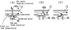
- Fig. 2 is a multiple view drawing for describing specific configuration examples and arrangement environments of an EGR valve shown in Fig. 1.
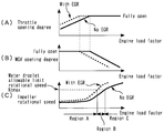
- Fig. 3 is a multiple view drawing that represents the settings of a throttle opening degree and a WGV opening degree with respect to an engine load factor that are used in Embodiment 1 of the present invention, and also represents, from the viewpoint of the impeller rotational speed, an engine load region in which the occurrence of condensed water constitutes a problem under the aforementioned settings.
- Fig. 4 is a multiple view drawing illustrating time charts for describing an overview of impeller rotational speed control that is performed taking a region B shown in Fig.
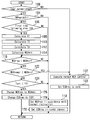
- Fig. 5 is a flowchart of a routine executed in Embodiment 1 of the present invention.
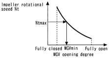
- Fig. 6 is a view that represents a relation between a turbine rotational speed Nt and a WGV opening degree under a uniform exhaust gas flow rate.
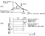
- Fig. 7 is a multiple view drawing for describing a combination between a water droplet allowable limit rotational speed Ntmax that is determined in accordance with the diameter of water droplets flowing into a compressor, a WGV opening degree within a range in which the impeller rotational speed Nt does not exceed Ntmax, and an EGR valve opening degree.
- Fig. 8 is a multiple view drawing illustrating time charts that represent operations when impeller rotational speed control is executed in Embodiment 2 of the present invention.
- Fig. 9 is a flowchart of a routine executed in Embodiment 2 of the present invention.
- Fig. 10 is a flowchart of a routine executed in Embodiment 3 of the present invention.
- Fig. 11 is a flowchart of a routine executed in a variation of Embodiment 3 of the present invention.
- Fig. 12 is a flowchart of a routine executed in Embodiment 4 of the present invention.
- Fig. 13 is a flowchart of a routine executed in Embodiment 5 of the present invention.
- Embodiment 1 is a view for describing the system configuration of an internal combustion engine 10 of Embodiment 1 of the present invention.
- a system of the present embodiment includes an internal combustion engine (as one example, a spark-ignition gasoline engine) 10.
- An intake passage 12 and an exhaust passage 14 communicate with each cylinder of the internal combustion engine 10.
- An air cleaner 16 is installed in the vicinity of an inlet of the intake passage 12.
- An air flow meter 18 that outputs a signal in accordance with a flow rate of air that is drawn into the intake passage 12, and an intake air temperature sensor 20 for detecting the temperature of intake air are respectively provided in the air cleaner 16.
- a compressor 22a of a turbocharger 22 is arranged downstream of the air cleaner 16. The compressor 22a is integrally connected through a connecting shaft with a turbine 22b arranged in the exhaust passage 14.
- the compressor 22a is of a type that has a centrifugal impeller, as long as a compressor that is an object of the present invention is of a type in which a problem that is described later (an erosion phenomenon with respect to the impeller that is caused by water droplets colliding with the impeller) arises, the compressor is not limited to a type that has a centrifugal impeller.
- a water-cooled intercooler 24 for cooling air that was compressed by the compressor 22a is provided downstream of the compressor 22a.
- An electronically controlled throttle valve 26 is provided downstream of the intercooler 24.
- An exhaust gas purification catalyst (as one example, a three-way catalyst) 28 is arranged in the exhaust passage 14 at a position that is on a downstream side relative to the turbine 22b.
- An exhaust bypass passage 30 is also connected to the exhaust passage 14.
- the exhaust bypass passage 30 connects an inlet side and an outlet side of the turbine 22b in a manner that bypasses the turbine 22b.
- a waste gate valve (WGV) 32 for opening and closing the exhaust bypass passage 30 is installed in the exhaust bypass passage 30.
- WGV 32 is a waste gate valve that is driven by an electric motor.
- the internal combustion engine 10 illustrated in Fig. 1 also includes a low-pressure loop (LPL) type EGR device 34.
- the EGR device 34 includes an EGR passage 36 that connects the exhaust passage 14 on the downstream side of the exhaust gas purification catalyst 28 with the intake passage 12 on the upstream side of the compressor 22a.
- An EGR cooler 38 and an EGR valve 40 are respectively provided in the EGR passage 36 in that order from an upstream side of a flow of EGR gas when the EGR gas is introduced into the intake passage 12.
- the EGR cooler 38 is provided for cooling EGR gas that flows through the EGR passage 36.
- the EGR valve 40 is provided for regulating the amount of EGR gas that passes through the EGR passage 36 and recirculates to the intake passage 12.
- the system illustrated in Fig. 1 also includes an ECU (electronic control unit) 50.
- the ECU 50 includes a central processing unit (CPU), a memory circuit constituted by a ROM and a RAM or the like, and input and output ports and the like.
- CPU central processing unit
- memory circuit constituted by a ROM and a RAM or the like
- input and output ports and the like input and output ports and the like.
- various sensors for detecting the operating state of the internal combustion engine 10 such as a crank angle sensor 52 for detecting the engine speed, a water temperature sensor 54 for detecting the engine cooling water temperature, and an oil temperature sensor 55 for detecting the engine lubricating oil temperature are electrically connected to an input port of the ECU 50.
- various actuators for controlling operations of the internal combustion engine 10 such as a fuel injection valve 56 for supplying fuel to the internal combustion engine 10 and an ignition device 58 for igniting an air-fuel mixture in the cylinders are electrically connected to an output port of the ECU 50.
- an accelerator position sensor 60 for detecting a depression amount of an accelerator pedal (accelerator position) of the vehicle in which the internal combustion engine 10 is mounted is also connected to the input port of the ECU 50.
- the ECU 50 controls the operations of the internal combustion engine 10 by actuating the various actuators in accordance with the output of the various sensors described above and predetermined programs.
- Fig. 2 is a multiple view drawing for describing specific configuration examples and arrangement environments of the EGR valve 40 shown in Fig. 1.
- a poppet-type EGR valve 40a, a flap-type EGR valve 40b, or a butterfly-type EGR valve 40c that are illustrated in Fig. 2(A) to Fig. 2(C) can be used as the EGR valve 40 of the present embodiment.
- the EGR valve 40 when the EGR valve 40 is in a closed state the surface of the valve body and the valve stem on the intake passage 12 side is exposed to low-temperature intake air (fresh air).
- the wall surface of the EGR passage 36 and the intake passage 12 around the EGR valve 40 is configured so as to be heated by the engine cooling water.
- the configuration is such that the surface of the EGR valve on the intake passage 12 side is liable to be directly exposed to intake air while the EGR valve is closed, as in the configuration illustrated in Fig. 2(A), even if the wall surface of the passage around the EGR valve is heated, it is difficult for the EGR valve itself to become warm and also to keep the EGR valve warm. Therefore, even after warming up is completed, if the EGR valve that is in a closed state is cooled to a temperature that is less than or equal to the dew-point temperature of exhaust gas (more specifically, exhaust gas that is present inside the EGR passage on an upstream side relative to the EGR valve) by low-temperature intake air, condensed water will be generated on the surface of the EGR valve.
- the dew-point temperature of exhaust gas more specifically, exhaust gas that is present inside the EGR passage on an upstream side relative to the EGR valve
- condensed water that has attached to the EGR valve will flow all at once into the intake passage. More specifically, water droplets that were attached to the EGR valve will detach from the EGR valve when the valve is opened, and there is the possibility that water droplets that have a large diameter will flow into the compressor. If water droplets that have flowed into the intake passage are drawn into the compressor, there is a concern that the water droplets will collide with the impeller of the compressor and an erosion phenomenon will thus occur at the impeller.
- the occurrence of an erosion phenomenon at an impeller is caused by the fact that the relative velocity between water droplets and the impeller is large and that the inertia (mass) of the water droplets is also large. That is, the occurrence of the aforementioned phenomenon is due to the fact that an impulse that the impeller receives from the water droplets is large. Accordingly, it can be said that the occurrence of an erosion phenomenon can be prevented by reducing the size of the water droplets that flow into the compressor or by lowering the rotational speed of the impeller.
- Fig. 3 is a multiple view drawing that represents the settings of the throttle opening degree and the WGV opening degree with respect to an engine load factor that are used in Embodiment 1 of the present invention, and also represents, from the viewpoint of the impeller rotational speed, an engine load region in which the occurrence of condensed water constitutes a problem under the aforementioned settings.
- the WGV 32 is controlled to the closing side in accordance with an increase in the required engine load factor while the throttle opening degree remains constant.
- the turbine 22b is rotated by exhaust energy and actual supercharging is started.
- the impeller rotational speed increases accompanying a decrease in the WGV opening degree.
- EGR gas is introduced (broken line)
- the introduction of EGR gas is implemented not only in a natural aspiration region in which the WGV 32 is opened fully, but also in one part of a supercharging region in which the WGV 32 is closed relative to the full opening degree.
- the basic method for controlling the throttle valve 26 and the WGV 32 in a case where EGR gas is introduced is the same as the case where EGR gas is not introduced.
- the throttle opening degree is made greater than the degree thereof in a case where EGR gas is not introduced under the same engine load factor.
- the throttle opening degree becomes the full opening degree.
- the WGV 32 is therefore configured so that the WGV 32 begins to close at a lower engine load factor than a value in the case where EGR gas is not introduced.
- the degree of divergence of the broken line relative to the solid line for each of the throttle opening degree and the WGV opening degree shown in Fig. 3(A) and Fig. 3(B), respectively is a degree of divergence at a certain EGR rate, and the degree of divergence increases as the EGR rate that is used increases.
- the impeller rotational speed during EGR gas introduction becomes higher overall in comparison to when EGR gas is not introduced.
- the impeller rotational speed during EGR gas introduction becomes higher than that at a time when EGR gas is not introduced because the throttle opening degree is made relatively larger for ensuring the same engine load factor.
- a water droplet allowable limit rotational speed (hereunder, also referred simply to as "limit rotational speed") Ntmax is set with respect to the impeller rotational speed.
- the water droplet allowable limit rotational speed Ntmax is a value that is set in advance so as to include a predetermined margin as an impeller rotational speed at which the occurrence of an erosion phenomenon is not a concern even if condensed water that was attached to the closed EGR valve 40 flows into the compressor 22a when the EGR valve 40 is opened.
- the water droplet allowable limit rotational speed Ntmax is a compressor rotational speed that is allowed in a case where it is supposed that droplets of condensed water that were attached to the closed EGR valve 40 will flow into the compressor 22a when the EGR valve 40 is opened.
- the diameter of water droplets that flow into the compressor 22a depends on the hardware condition of the internal combustion engine 10 (for example, the length of the intake passage 12 from a merging portion with the EGR passage 36 to the compressor inlet).
- a relation as shown in Fig. 7(A) that is described later exists between the diameter of the water droplets and the impeller rotational speed, and the limit rotational speed Ntmax under an assumed diameter of the water droplets is determined taking into account the relation in Fig. 7(A).
- the rotational speed of the impeller of the compressor 22a (that is, the compressor rotational speed) is equal to the turbine rotational speed Nt.
- the aforementioned two rotational speeds are not particularly distinguished from each other in the following description, and are referred to as “impeller rotational speed Nt” or “turbine rotational speed Nt”.
- a region A that is illustrated in Fig. 3(C) is an engine load region for which an engine load factor when the impeller rotational speed Nt reaches the limit rotational speed Ntmax in a state in which EGR gas is introduced is taken as an upper limit. That is, the region A is a region in which the impeller rotational speed Nt does not exceed the limit rotational speed Ntmax even if the impeller rotational speed Nt is increased for introduction of EGR gas. Accordingly, it can be said that in the region A it is not necessary to implement a special countermeasure with respect to the inflow of the above described condensed water into the compressor 22a.
- the region B is an engine load region that continues from the region A, and is on a high load side relative to the region A.
- An upper limit of the region B is an engine load factor at which the impeller rotational speed Nt reaches the limit rotational speed Ntmax in a state in which EGR gas is not introduced. Accordingly, in the region B, although the impeller rotational speed Nt will not exceed the limit rotational speed Ntmax if EGR gas is not introduced, the impeller rotational speed will exceed the limit rotational speed Ntmax when the impeller rotational speed Nt increases accompanying the introduction of EGR gas.
- a configuration is adopted so that in a case where introduction of EGR gas is started under a situation in which the temperature of the EGR valve 40 is less than or equal to a predetermined value X1 and where the impeller rotational speed Nt that is required when starting the introduction of the EGR gas is higher than the limit rotational speed Ntmax, the impeller rotational speed Nt after introduction of EGR gas starts is restricted so as not to exceed the limit rotational speed Ntmax.
- a configuration is adopted that restricts the impeller rotational speed Nt so as not to exceed the limit rotational speed Ntmax throughout a protection time period T3 after introduction of EGR gas starts.
- this kind of impeller rotational speed control corresponds to "lowering the impeller rotational speed Nt to a speed that is less than the limit rotational speed Ntmax throughout the protection time period T3 after introduction of EGR gas starts in a case where the EGR valve 40 is opened to start the introduction of EGR gas under a situation in which the engine load region is in region B and where condensed water is generated at the EGR valve 40." Since the present impeller rotational speed control is characteristic control of the present embodiment, the details thereof will be described later. Note that, an engine load factor that is a boundary between region A and region B changes as the EGR rate changes. Accordingly, when the EGR rate changes, the region B that is the object of the present impeller rotational speed control also changes.
- a region C is an engine load region that continues from the region B, and is on the high load side relative to the region B.
- the impeller rotational speed Nt exceeds the limit rotational speed Ntmax in a state in which EGR gas is not introduced. Accordingly, under a situation in which the engine load region is in the region C, even if condensed water has been generated at the EGR valve 40 at the time that introduction of EGR gas starts, the impeller rotational speed Nt cannot be lowered to a speed that is less than or equal to the limit rotational speed Ntmax.
- Fig. 4 is a multiple view drawing illustrating time charts for describing an overview of the impeller rotational speed control that is performed taking the region B that is illustrated in Fig. 3 as an object. Note that, as one example, Fig. 4 represents a situation in which introduction of EGR gas is started during warm-up running in a state in which the accelerator position is made constant (that is, a state in which the torque that the driver demands with respect to the internal combustion engine 10 is constant).
- Waveforms that are illustrated by broken lines in Figs. 4(D) to (F) indicate operation at a normal time (more specifically, at the time of a high intake air temperature at which condensed water is not generated on the surface of the EGR valve 40 that is in a closed state). If the EGR valve 40 is opened without giving any particular consideration thereto, the intake air amount will decrease when EGR gas is introduced into the intake passage 12, and the engine torque will decrease in accompaniment therewith.
- the region B is a region in which the engine load factor (intake air amount) is controlled by adjusting the WGV opening degree as described above. Consequently, to avoid a decrease in the intake air amount as described above, the WGV opening degree is controlled to an opening degree towards the closed side as indicated by the broken line in Fig.
- the EGR valve opening degree is increased in order to increase the EGR gas amount.
- the WGV opening degree is controlled toward the closed side accompanying this change in the EGR valve opening degree.
- the WGV opening degree is set so as to become WGVmin that is a WGV opening degree corresponding to the limit rotational speed Ntmax under the current exhaust gas flow rate (see the solid line in Fig. 4(E)). That is, an opening degree WGVmin that is further on the open side than the WGV opening degree at the time of normal operation is used.
- the collision speed between water droplets and the impeller when water droplets flow into the compressor 22a accompanying opening of the EGR valve 40 can be lowered (that is, an impulse that the impeller receives from water droplets can be reduced). Consequently, the occurrence of an erosion phenomenon can be prevented.
- the intake air amount (engine torque) cannot be maintained at a constant amount with respect to before and after the introduction of EGR gas. More specifically, the supercharging pressure will decrease if the impeller rotational speed Nt is lowered. If the supercharging pressure decreases, the intake air amount and the EGR gas amount will also decrease (that is, the overall amount of gas drawn into the cylinders will decrease).
- an EGR valve opening degree EGR1 in this case is an opening degree that corresponds to an EGR gas amount (Gegr1 that is described later) that can be introduced under a supercharging pressure that is obtained under a situation in which the WGV opening degree has been controlled to the opening degree WGVmin without changing the intake air amount before and after opening of the EGR valve 40.
- the protection time period T3 is a period in which there is a possibility of water droplets that were attached to the EGR valve 40 flowing into the compressor 22a after opening of the EGR valve 40. For example, it is favorable to set the protection time period T3 according to the method described below.
- the protection time period T3 for protecting the impeller is represented as the sum of a valve detachment time period T1 and an intake pipe transit time period T2.
- the valve detachment time period T1 is a time period from a time point at which the EGR valve 40 starts to open until a time point at which water droplets that are attached to the surface of the closed EGR valve 40 start to detach from the EGR valve 40 as a result of being drawn by a flow of EGR gas.
- the intake pipe transit time period T2 is a time period from a time point at which water droplets start to detach from the EGR valve 40 until a time point at which the water droplets finish arriving at the inlet of the compressor 22a.
- Form (a) is a form in which the water droplets attach to the wall surface of the intake passage 12, flow along the wall surface, and arrive at the inlet of the compressor 22a.
- Form (b) is a form in which although the water droplets attach to the wall surface of the intake passage 12 and flow along the wall surface, the water droplets evaporate before arriving at the inlet of the compressor 22a.
- Form (c) is a form in which the water droplets fly through the space inside the intake passage 12 and arrive at the compressor 22a without attaching to the wall surface of the intake passage 12. It is considered that, in practice, a portion of the water droplets that flow into the intake passage 12 move in the manner of form (c), and the remaining water droplets move in the manner of either one of or both of form (a) and form (b).
- water droplets that have attached to the wall surface of the intake passage arrive at the inlet of the compressor or evaporate partway along the intake passage basically depends on the hardware conditions of the internal combustion engine (specifically, the length of the intake passage from an EGR gas introduction portion to the compressor). Further, in a case where a configuration is adopted in which the intake passage on an upstream side of the compressor is heated by engine cooling water, as in the case of the internal combustion engine 10, it is also conceivable that whether water droplets flow along the wall surface and arrive at an inlet of the compressor or evaporate partway along the intake passage changes depending on the engine cooling water temperature.
- time-of-flight T22 time required for water droplets to complete their flight
- time-of-sliding T21 time required for water droplets to complete their arrival at the inlet of the compressor via the wall surface
- the time-of-flight T22 may be treated as the intake pipe transit time period T2.
- the internal combustion engine is an engine with respect to which, on the basis of a determination based on the hardware condition that is described above, it can be said that water droplets that attached to the wall surface of the intake passage do not arrive at the compressor inlet, the time-of-flight T22 may be treated as the intake pipe transit time period T2.
- the internal combustion engine is an engine with respect to which, on the basis of a determination based on the hardware condition that is described above, it can be said that water droplets that attached to the wall surface of the intake passage sometimes arrive at the compressor inlet, the time-of-sliding T21 may be treated as the intake pipe transit time period T2.
- a time period that is used as the intake pipe transit time period T2 may be changed in accordance with the engine cooling water temperature. Specifically, under a water temperature condition with respect to which it can be said that water droplets evaporate because the engine cooling water temperature is high, the time-of-flight T22 may be treated as the intake pipe transit time period T2, and under a water temperature condition with respect to which it can be said that water droplets arrive at the compressor inlet because the engine cooling water temperature is low, the time-of-sliding T21 may be treated as the intake pipe transit time period T2.
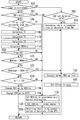
- FIG. 5 is a flowchart illustrating a routine that is executed by the ECU 50 in Embodiment 1 of the present invention. Note that the present routine is repeatedly executed for each predetermined control period.
- the ECU 50 determines whether or not a predetermined EGR introduction condition (Cegr) is established (step 100). More specifically, the EGR introduction condition is established when the engine cooling water temperature is within a predetermined range and a predetermined EGR prohibition condition is not established. Introduction of EGR gas is started accompanying establishment of the EGR introduction condition.
- a predetermined EGR introduction condition (Cegr) is established. More specifically, the EGR introduction condition is established when the engine cooling water temperature is within a predetermined range and a predetermined EGR prohibition condition is not established. Introduction of EGR gas is started accompanying establishment of the EGR introduction condition.
- step 102 If it is determined in step 100 that the EGR introduction condition is not established, the ECU 50 executes normal WGV control (step 102). According to the normal WGV control, the WGV opening degree is controlled so as to become a required WGV opening degree in accordance with the current engine load factor and engine speed. Next, the ECU 50 proceeds to step 103 and sets the required EGR valve opening degree (EGRreq) to zero. That is, in this case, introduction of EGR gas is not performed (is prohibited).
- EGRreq required EGR valve opening degree
- the ECU 50 subsequently determines whether or not the temperature of the EGR valve 40 (TMPegr) is less than or equal to the predetermined value X1 (step 104).
- predetermined value X1 refers to a temperature at which condensation of moisture starts to occur at the EGR valve 40 (that is, the dew-point temperature of exhaust gas that is present in the vicinity of the EGR valve 40 that is in a closed state).
- the present control may also be executed in a manner that includes a safety margin so that the control is executed under a situation in which, although the EGR valve temperature is higher than the dew-point temperature, there is a possibility that condensed water has been generated on the surface of the EGR valve 40 since the EGR valve temperature is a temperature that is close to the dew-point temperature.
- a temperature that is higher by a predetermined margin with respect to the aforementioned dew-point temperature of the exhaust gas may also be used as the above described predetermined value X1.
- a constant value that was determined in advance can be used as the dew-point temperature of the exhaust gas that is to be used as the predetermined value X1.
- the dew-point temperature may be calculated as a variable value that is based on the temperature of the exhaust gas. Further, since the dew-point temperature calculated in this case is the dew-point temperature of exhaust gas that stagnates in the EGR passage 36 in the vicinity of the EGR valve 40 (that is, gas that includes a fixed proportion of moisture), a constant value or the like may be used as described above. However, the dew-point temperature is a value that changes in accordance with the humidity of the gas. Therefore, a configuration may also be adopted in which the humidity of the stagnant exhaust gas is detected or estimated, and the dew-point temperature is calculated in a manner that takes the humidity into consideration.
- the EGR valve temperature can be estimated as a value that is calculated by means of a function of the intake air temperature, the engine cooling water temperature and time.
- a map (not illustrated in the drawings) that defines a base value T eo of the temperature of the EGR valve 40 by means of a relation with the intake air temperature and the engine cooling water temperature is stored in the ECU 50.
- base value T eo refers to a steady-state temperature of the EGR valve 40 when the intake air temperature and the engine cooling water temperature are each an arbitrary temperature.
- a value T eo corresponding to the intake air temperature that is detected by the intake air temperature sensor 20 and the engine cooling water temperature that is detected by the water temperature sensor 54 is acquired by referring to the map.
- a current temperature T n of the EGR valve 40 that changes in a manner that is accompanied by a temporal lag upon receiving the influence of a change in the intake air temperature and engine cooling water temperature is calculated in accordance with Equation (1).
- T n-1 represents the previous value of the temperature of the EGR valve 40
- k represents a smoothing coefficient (0 ⁇ k ⁇ 1) that is set in advance.
- the water temperature sensor 54 measures the engine cooling water temperature at a position that has a correlation with the engine cooling water temperature in the housing of the EGR valve 40.
- T n T n-1 +(T eo - T n-1 ) ⁇ k ...
- the EGR valve temperature that is used in step 104 may be a temperature that is detected by a sensor if it is possible to do so.
- the intake air temperature is less than or equal to the predetermined value X1
- it may be determined that the situation is one in which the EGR valve temperature is less than or equal to the predetermined value X1.
- a temperature at a position that is close to the site at which the EGR valve 40 is disposed (that is, a position in the vicinity of the compressor inlet) is preferable as the intake air temperature referred to in this case.
- the intake air temperature at the inlet of the intake passage 12 (nearly equal to outdoor air temperature) that is detected by the intake air temperature sensor 20 may be substituted for the intake air temperature at the compressor inlet, or the outdoor air temperature itself may be used, or a temperature on a downstream side of the compressor may be used.
- step 104 If it is determined in step 104 that the temperature of the EGR valve is higher than the predetermined value X1, the ECU 50 proceeds to step 118. In contrast, if it is determined that the temperature of the EGR valve is less than or equal to the predetermined value X1, the ECU 50 determines whether or not the current processing cycle is the first cycle after the EGR valve temperature fell below the predetermined value X1 (step 106). If the result of the present determination is affirmative, the ECU 50 executes the series of processing in steps 108 to 114. On the other hand, if the result of the present determination is negative, the ECU 50 proceeds to step 116.
- the ECU 50 calculates the valve detachment time period T1.
- the flow rate of EGR gas that passes through the EGR valve 40 is the dominant factor with respect to the valve detachment time period T1. Therefore, in this case, the ECU 50 calculates the valve detachment time period T1 in accordance with a map (not illustrated in the drawings) that predefines the valve detachment time period T1 so as to be a function of the EGR valve opening degree. In this map, the valve detachment time period T1 is set so as to become shorter as the EGR valve opening degree decreases (that is, as the flow rate of the EGR gas increases).
- the ECU 50 calculates the time-of-sliding T21 or the time-of-flight T22 as the intake pipe transit time period T2.
- the method described above can be used to determine which of the time-of-sliding T21 and the time-of-flight T22 is to be calculated in the present step 110.
- the time-of-sliding T21 With respect to the time-of-sliding T21, the contribution of the intake air amount (mass flow rate) is large. Consequently, in this case, the ECU 50 calculates the time-of-sliding T21 in accordance with a map (not illustrated in the drawings) that predefines the time-of-sliding T21 so as to be a function of the intake air amount.
- the time-of-sliding T21 is set so as to become shorter as the intake air amount increases. Furthermore, with respect to the time-of-flight T22, the contribution of the flow rate of the intake air is large. Further, the flow rate of intake air is in a proportional relation with the intake air amount. Consequently, in this case, the ECU 50 calculates the time-of-flight T22 in accordance with a map (not illustrated in the drawings) that predefines the time-of-flight T22 so as to be a function of the intake air amount. In this map, the time-of-flight T22 is set so as to decrease as the intake air amount increases.
- step 112 the ECU 50 calculates the protection time period T3 as the sum of the valve detachment time period T1 and the time-of-sliding T21, or as the sum of the valve detachment time period T1 and the time-of-flight T22.
- the ECU 50 calculates the lower limit value WGVmin of the WGV opening degree that corresponds to the limit rotational speed Ntmax under the current exhaust gas flow rate (step 114).
- Fig. 6 is a view that represents the relation between the turbine rotational speed Nt and the WGV opening degree under the same exhaust gas flow rate. If the exhaust gas flow rate is constant, as shown in Fig. 6, the turbine rotational speed Nt increases as the WGV opening degree decreases. In this case, a value that is previously set as a constant value that does not depend on the operating state (engine speed and engine load factor) is used as the limit rotational speed Ntmax. Note that, since the limit rotational speed Ntmax is set while taking the size of the aforementioned impulse into consideration, the limit rotational speed Ntmax may change in accordance with the amount of condensed water that is generated at the EGR valve 40. Specifically, since the generated amount of condensed water increases as the temperature of the EGR valve 40 that is acquired by estimation or the like decreases, the limit rotational speed Ntmax may be lowered in accompaniment therewith.
- the ECU 50 has information (a map or the like) showing the relation between the turbine rotational speed Nt and the WGV opening degree as shown in Fig. 6 for respective predetermined exhaust gas flow rates, and in the present step 114 the lower limit value WGVmin corresponding to the limit rotational speed Ntmax is calculated utilizing the aforementioned relation at the current exhaust gas flow rate.
- the exhaust gas flow rate is equivalent to the sum of a total in-cylinder intake gas amount Gcyl and the fuel injection amount under a steady state, and can be calculated as the sum of the intake air amount Ga that is measured by the air flow meter 18, an EGR gas amount Gegr, and the fuel injection amount.
- the EGR gas amount Gegr can be calculated based on the differential pressure between the intake air and exhaust gas and the EGR valve opening degree.
- the ECU 50 determines whether or not the required WGV opening degree (WGVreq) is less than the lower limit value WGVmin (step 116).
- the ECU 50 uses processing that is different to the present routine to sequentially calculate the required WGV opening degree as a value that is based on an engine load parameter, the engine speed and the basic required EGR valve opening degree.
- the engine load factor (in-cylinder air charging rate) or the intake air amount Ga or the like corresponds to the engine load parameter in this case.
- the basic required EGR valve opening degree is also sequentially calculated by processing that is different to the present routine. Specifically, the basic required EGR valve opening degree is calculated as a value that is based on an engine load parameter, the engine speed and the engine cooling water temperature.
- step 116 If it is determined in step 116 that the required WGV opening degree is greater than or equal to the lower limit value WGVmin, the ECU 50 proceeds to step 118 and sets the required WGV opening degree (WGVreq) using a value in accordance with a normal instruction (that is, adjustment of the required WGV opening degree is not performed).
- step 120 sets the required EGR valve opening degree (EGRreq) using a value in accordance with a normal instruction (that is, the basic required EGR valve opening degree). That is, adjustment of the required EGR valve opening degree is also not performed.
- the ECU 50 determines whether or not the WGV opening degree (the required WGV opening degree or actual WGV opening degree) immediately prior to the current introduction of EGR gas (WGVnoegr) is less than the lower limit value WGVmin (step 122). If the result of the present determination is affirmative, that is, if the impeller rotational speed Nt immediately prior to the current introduction of EGR gas (that is, in a state where EGR gas is not being introduced) is already higher than the limit rotational speed Ntmax, the ECU 50 proceeds to step 102. According to this processing, in a case where impeller rotational speed control cannot be performed because the engine load region is in the aforementioned region C, introduction of EGR gas is prohibited (step 103).
- the ECU 50 determines whether or not a continuous time period from the time point at which EGR introduction starts (Tcnt) is shorter than the aforementioned protection time period T3 (step 124). If it is determined as a result that the protection time period T3 has not elapsed, the ECU 50 changes the required WGV opening degree (WGVreq) to the lower limit value WGVmin (step 126), and also changes the basic required EGR valve opening degree to the EGR valve opening degree EGR1 (see Fig. 4(D)) that is in accordance with the lower limit value WGVmin (step 128). Further, if the protection time period T3 has elapsed, the processing in steps 118 and 120 is executed.
- a case where the EGR introduction condition is established and introduction of EGR gas is started in a situation in which the temperature of the EGR valve 40 is less than or equal to the predetermined value X1 corresponds to a case in which there is a possibility that condensed water that is attached to the EGR valve 40 that is in a closed state will flow into the compressor 22a accompanying opening of the EGR valve 40.
- the routine illustrated in Fig. 5 that is described above, in such a case, if the required WGV opening degree when EGR gas introduction starts is lower than the lower limit value WGVmin (is on the closed side relative thereto), the required WGV opening degree is restricted to the lower limit value WGVmin.
- the protection time period T3 is a time period in which there is a possibility that droplets of condensed water from the EGR valve 40 will flow into the compressor 22a.
- the impeller rotational speed control a state in which the impeller rotational speed Nt becomes higher than the water droplet allowable limit rotational speed Ntmax can be avoided under a situation in which there is a possibility that the water droplets will flow into the compressor 22a.
- the present control is a countermeasure according to which an inflow of water droplets that were attached to the closed EGR valve 40 into the intake passage 12 together with EGR gas when the EGR valve 40 is opened is itself allowed.
- the present countermeasure makes it possible to suppress the occurrence of an erosion phenomenon while maintaining as much as possible the occasions for introducing EGR gas (for example, while introducing EGR gas at an early stage during engine warm-up).
- the protection time period T3 is determined based on the valve detachment time period T1 and the intake pipe transit time period T2 (time-of-sliding T21 or time-of-flight T22).
- the protection time period T3 for which the impeller rotational speed Nt is restricted can be set to the required minimum time period in a manner that takes into consideration parameters (in the above described example, the EGR valve opening degree and the intake air amount) that mainly influence the behavior of water droplets that detach from the EGR valve 40 and flow into the intake passage 12, and also the form of movement of the water droplets after the water droplets flow into the intake passage 12.
- restriction of the EGR gas amount for suppressing torque changes that accompany restriction of the impeller rotational speed Nt can also be suppressed to the required minimum, and hence adverse influences of the present control on NOx emissions can be suppressed to a minimum.
- the compressor rotational speed that is obtained in a state in which the WGV opening degree under an exhaust gas flow rate at the time of calculating a required WGV opening degree is controlled so as to become a required WGV opening degree that is calculated in the processing in step 116 corresponds to "basic required compressor rotational speed" in the first aspect of the present invention
- the water droplet allowable limit rotational speed Ntmax corresponds to "predetermined rotational speed” in the first aspect of the present invention.
- “compressor control means" in the first aspect of the present invention is realized by the ECU 50 controlling the WGV 32 so as to become the lower limit value WGVmin.
- the basic required EGR valve opening degree that is calculated by the ECU 50 as a value that is based on an engine load parameter, the engine speed and the engine cooling water temperature corresponds to "basic required EGR valve opening degree" in the fifth aspect of the present invention
- the EGR valve opening degree EGR1 corresponds to "first required EGR valve opening degree” in the fifth aspect of the present invention.
- “EGR valve control means" in the fifth aspect of the present invention is realized by the ECU 50 controlling the EGR valve opening degree so as to become the EGR valve opening degree EGR1.
- Embodiment 2 of the present invention will be described referring to Fig. 7 to Fig. 9.
- the system of the present embodiment can be realized by using the hardware configuration illustrated in Fig. 1, and causing the ECU 50 to execute the routine shown in Fig. 9, described later, instead of the routine shown in Fig. 5.
- Fig. 7 is a multiple view drawing for describing a combination of the water droplet allowable limit rotational speed Ntmax that is determined in accordance with the diameter of water droplets that flow into the compressor 22a, a WGV opening degree in a range in which the impeller rotational speed Nt does not exceed Ntmax, and the EGR valve opening degree.
- An "NG region” and an “OK region” that are shown in Fig. 7(A) represent a region in which an impeller erosion phenomenon constitutes a problem and a region in which the impeller erosion phenomenon does not constitute a problem, respectively.
- the diameter of water droplets that can actually be generated in the internal combustion engine 10 is determined by the hardware conditions of the internal combustion engine 10 as described in the foregoing, the diameter of the water droplets can be ascertained in advance by experiment or the like. Accordingly, the limit rotational speed Ntmax can be determined as shown in Fig.
- the limit rotational speed Ntmax is defined in accordance with the hardware conditions of the internal combustion engine 10.
- the impeller rotational speed Nt is increased so as not to cause the intake air amount Ga (engine torque) to change. Therefore, according to the example in Embodiment 1, while giving consideration so as to ensure that the impeller rotational speed Nt does not exceed the limit rotational speed Ntmax, the WGV opening degree is controlled so as to become a lower limit value WGVmin that is less than the WGV opening degree immediately prior to the introduction of EGR gas.
- An EGR gas amount Gegr1 shown in Fig. 7(B) is an EGR gas amount that can be introduced under the supercharging pressure Pim that is obtained under a situation in which the WGV opening degree is set to the lower limit value WGVmin, without changing the intake air amount Ga before and after opening of the EGR valve 40.
- a combination between the WGV opening degree and the EGR valve opening degree under a condition in which the impeller rotational speed Nt is restricted so as not to exceed the limit rotational speed Ntmax is a combination that makes the WGV opening degree greater than the lower limit value WGVmin (sets the WGV opening degree to the open side relative to the lower limit value WGVmin)
- the combination is not limited to the combination (Setting Example 1) between the lower limit value WGVmin and the EGR valve opening degree EGR1 that is used in Embodiment 1.
- Setting Example 2 shown in Fig. 7(B) is an example that uses a combination of a WGV opening degree WGV2 and an EGR valve opening degree EGR2.
- the EGR valve opening degree EGR2 is smaller than the EGR valve opening degree EGR1.
- the WGV opening degree WGV2 is a WGV opening degree at which the intake air amount Ga is not caused to change between before and after opening of the EGR valve 40 when using the EGR valve opening degree EGR2.
- an EGR gas amount Gegr2 that is less than the EGR gas amount Gegr1 of Setting Example 1 is obtained under the WGV opening degree WGV2 that is further on the open side relative to the lower limit value WGVmin.
- a setting in which the EGR gas amount is made less than Gegr2 without changing the intake air amount Ga can also be obtained by setting the WGV opening degree still further to the open side relative to the WGV opening degree WGV2 while also setting the EGR valve opening degree still further to the closed side relative to the EGR valve opening degree EGR2.
- the EGR valve opening degree when executing the impeller rotational speed control is set to the EGR valve opening degree EGR2 that is less than the EGR valve opening degree EGR1 used in Embodiment 1. Operations of the internal combustion engine 10 when using this EGR valve opening degree setting will now be described referring to Fig. 8 taking a time when the engine is being warmed up as an example.
- the WGV opening degree WGV2 that is further on the open side relative to the lower limit value WGVmin is used.
- the impeller rotational speed Nt is controlled to an impeller rotational speed Nt2 that is lower than the limit rotational speed Ntmax. Since the valve detachment time period T1 is reduced in comparison to the control of Embodiment 1 by using the EGR valve opening degree EGR2, the protection time period T3 for the impeller is shortened. That is, it is possible to shorten the time period in which the impeller rotational speed control is executed and to return to the normal WGV opening degree and EGR valve opening degree control at an earlier timing.
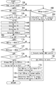
- FIG. 9 is a flowchart illustrating a routine that is executed by the ECU 50 in Embodiment 2 of the present invention. Note that, in Fig. 9, steps that are the same as steps shown in Fig. 5 according to Embodiment 1 are denoted by the same reference numerals, and a description of those steps is omitted or simplified.
- step 124 if it is determined in step 124 that the protection time period T3 has not elapsed, the ECU 50 executes the processing in steps 200 and 202 in that order.
- the ECU 50 changes the required EGR valve opening degree (EGRreq) from the basic required EGR valve opening degree at a time of starting EGR gas introduction to the EGR valve opening degree EGR2 (see Fig. 8(D)).
- the EGR valve opening degree EGR2 is set as an appropriate value within an EGR valve opening degree range that is smaller than the EGR valve opening degree EGR1 used in Embodiment 1.
- the EGR valve opening degree EGR 1 is an EGR valve opening degree at which the EGR gas amount can be maximized under a condition in which the WGV opening degree is not closed more than the lower limit value WGVmin.
- an EGR valve opening degree EGR2 that is previously set based on the results of experimentation or the like is stored in the ECU 50 as a value that can appropriately increase the flow velocity of gas that passes through the EGR valve in comparison to a case where the EGR valve opening degree is set to the EGR valve opening degree EGR1.
- the ECU 50 changes the required WGV opening degree (WGVreq) at the time of starting EGR gas introduction to the WGV opening degree WGV2.
- WGV opening degree WGV2 is a value that is set in advance as a WGV opening degree that does not cause the intake air amount Ga to change between before and after opening the EGR valve 40 when using the EGR valve opening degree EGR2.
- the EGR valve opening degree EGR2 corresponds to "second required EGR valve opening degree” in the sixth aspect of the present invention
- a compressor rotational speed that is obtained in a state in which the WGV opening degree under the exhaust gas flow rate at a time of calculating the WGV opening degree WGV2 is controlled so as to become the WGV opening degree WGV2 corresponds to "first required compressor rotational speed" in the sixth aspect of the present invention.
- Embodiment 3 of the present invention will be described referring to Fig. 10.
- the system of the present embodiment can be realized by using the hardware configuration illustrated in Fig. 1, and causing the ECU 50 to execute the routine shown in Fig. 10, described later, instead of the routine shown in Fig. 5 of Embodiment 1.
- the control of the present embodiment may be control that is combined with the control (routine illustrated in Fig. 9) of Embodiment 2.
- the EGR valve 40 has a heat capacity. Consequently, with the exception of a time of cold starting from a state in which the EGR valve temperature is less than or equal to the predetermined value X1, in a case where the EGR valve 40 was closed in a state in which the EGR valve 40 had been heated by high-temperature EGR gas while open, even if the intake air temperature is equal to or less than the predetermined value X1, it is not the case that the EGR valve temperature immediately becomes less than or equal to the predetermined value X1.
- a water droplet attachment time period T4 is supposed for a case in which, after introduction of EGR gas is paused and the EGR valve 40 is closed during engine operation, introduction of EGR gas is resumed while the engine operation is continuing.
- the water droplet attachment time period T4 is a time period from a time point at which the EGR valve 40 that was heated by high-temperature EGR gas while open is closed, until a time point at which water droplets start to attach to the valve surface due to the closed EGR valve 40 being exposed to low-temperature intake air.
- the water droplet attachment time period T4 has not elapsed, water droplets do not attach to the valve surface even in a situation in which the intake air temperature becomes less than or equal to the predetermined value X1 while the EGR valve 40 is closed. Because of this, if the aforementioned impeller rotational speed control is executed at a time that introduction of EGR gas is resumed under such circumstances in which water droplets do not attach to the valve surface because the water droplet attachment time period T4 has not elapsed, the amount of EGR gas will decrease unnecessarily.
- a configuration is adopted in which, when the intake air temperature is less than or equal to the predetermined value X1 and a time period in which the EGR introduction is paused has continued for a period of time that is equal to or greater than the water droplet attachment time period T4, it is determined that the situation is one in which condensed water is generated at the EGR valve 40. Further, in a case where introduction of EGR gas is started at or after a time point at which the water droplet attachment time period T4 elapses, the aforementioned impeller rotational speed control is executed.
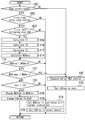
- FIG. 10 is a flowchart illustrating a routine that is executed by the ECU 50 in Embodiment 3 of the present invention. Note that, in Fig. 10, steps that are the same as steps shown in Fig. 5 according to Embodiment 1 are denoted by the same reference numerals, and a description of those steps is omitted or simplified.
- step 100 if it is determined in step 100 that the EGR introduction condition (Cegr) is established, the ECU 50 determines whether or not the situation is one in which the EGR valve temperature becomes less than or equal to the predetermined value X1 based on whether or not the intake air temperature (TMPin) is less than or equal to the predetermined value X1 (step 301). On the other hand, if it is determined in step 100 that the EGR introduction condition is not established, the ECU 50 determines whether or not the time period for which EGR introduction has been paused (EGR cut duration) is equal to or greater than the water droplet attachment time period T4 (step 300).
- EGR cut duration the time period for which EGR introduction has been paused
- Attachment of water droplets to the EGR valve 40 that is at a certain temperature is determined based on the time period for which the EGR valve 40 is cooled by low-temperature intake air. Consequently, in this case, the ECU 50 calculates the water droplet attachment time period T4 in accordance with a map (not illustrated in the drawings) in which the water droplet attachment time period T4 is previously defined so as to be a function of the intake air temperature and the intake air amount. In this map, the water droplet attachment time period T4 is set so as to become shorter as the intake air temperature becomes lower or as the intake air amount increases. Note that the water droplet attachment time period T4 may be determined in a manner that takes into consideration the EGR valve temperature at the time point at which the EGR valve 40 is closed.
- step 102 If the result of the present determination is negative, the ECU 50 proceeds to step 102, while if the result of the present determination is affirmative, the ECU 50 proceeds to step 302. In step 302, since the situation is one in which condensed water is generated at the EGR valve 40, the ECU 50 sets a condensation flag to "on".
- the ECU 50 determines whether or not the condensation flag is set to "on” (step 304). If the ECU 50 determines as a result that the condensation flag is "off”, the ECU 50 proceeds to step 118. That is, in this case, since the water droplet attachment time period T4 has not yet elapsed after establishment of the EGR introduction condition, execution of the impeller rotational speed control is prohibited. On the other hand, if the ECU 50 determines that the condensation flag is "on”, the ECU 50 proceeds to step 116. The condensation flag is set to "off” after the processing in step 120 is executed (step 306).
- the impeller rotational speed control is not executed in a case where the water droplet attachment time period T4 has not elapsed.
- control that takes into consideration transient differences between the intake air temperature and the EGR valve temperature after temporarily stopping the introduction of EGR gas takes as an object a case in which the introduction of EGR gas is resumed while operation of the engine is continuing after the EGR valve 40 was closed to temporarily stop the introduction of EGR gas.
- this control can also be applied to a case in which operation of the internal combustion engine 10 is stopped after the EGR valve 40 is closed in order to stop the introduction of EGR gas, and the engine is restarted during a period up to a time point at which the EGR valve temperature decreases to a temperature that is less than or equal to the predetermined value X1 while operation of the engine is stopped.
- the EGR valve temperature decreases towards the outdoor air temperature with the passage of time.
- the EGR valve temperature while the engine is stopped can be estimated based on the engine cooling water temperature or the engine lubricating oil temperature by ascertaining in advance the relation between the EGR valve temperature and the engine cooling water temperature or engine lubricating oil temperature. By using this estimation method, the EGR valve temperature can be estimated at the time point at which engine startup is started.
- a configuration may be adopted so that the above described impeller rotational speed control is not performed in a case where the estimated value of the EGR valve temperature when starting the engine is higher than the predetermined value X1, even in a case where introduction of EGR gas is started under a situation in which the intake air temperature is less than or equal to the predetermined value X1.
- Fig. 11 is a flowchart illustrating a routine that is executed by the ECU 50 in a variation of Embodiment 3 of the present invention. Note that, in Fig. 11, steps that are the same as steps shown in Fig. 10 according to Embodiment 3 are denoted by the same reference numerals, and a description of those steps is omitted or simplified.
- the ECU 50 determines whether or not the temperature of the EGR valve 40 at the time of engine startup (TMPegrsta) is less than or equal to the predetermined value X1 (step 400).
- the temperature of the EGR valve 40 at the time of engine startup can be estimated based on the engine cooling water temperature that is detected by the water temperature sensor 54 or based on the engine lubricating oil temperature that is detected by the oil temperature sensor 55.
- step 400 If the result determined in step 400 is that the temperature of the EGR valve 40 at engine startup is less than or equal to the predetermined value X1, the condensation flag is set to "on” (step 302). In contrast, if the result determined in step 400 is that the temperature of the EGR valve 40 at engine startup is higher than the predetermined value X1, the condensation flag is not set to "on".
- the result of the determination in step 304 is negative because the condensation flag is not set to "on". Therefore, restriction of the impeller rotational speed Nt by the processing in step 126 is not performed. Further, in this case, because the result of the determination in step 304 is negative, decreasing of the EGR valve opening degree by the processing in step 128 is also not performed.
- a time difference that corresponds to the amount of time required for the engine cooling water temperature to increase as far as the EGR permissible water temperature arises between a time point at which engine startup commences and a time point at which the EGR introduction condition. Because the EGR valve 40 is exposed to the flow of intake air after engine startup, in a case where the above described time difference has arisen, a difference arises between the EGR valve temperature that is estimated based on the engine cooling water temperature or the like and the EGR valve temperature at the time point at which the EGR introduction condition is established.
- an EGR temperature correction amount that is based on the intake air temperature, the intake air amount and the elapsed time period from the time point at which startup commences.
- Embodiment 4 of the present invention will be described referring to Fig. 12.
- the system of the present embodiment can be realized by using the hardware configuration illustrated in Fig. 1, and causing the ECU 50 to execute the routine shown in Fig. 12, described later, instead of the routine shown in Fig. 5 of Embodiment 1.
- Embodiment 4 In the above described Embodiments 1 to 3, in a case where the temperature of the EGR valve 40 at the time of starting introduction of EGR gas when the EGR introduction condition is established is less than or equal to the predetermined value X1 (the dew-point temperature of exhaust gas present in the vicinity of the EGR valve 40 that is in a closed state), a configuration is adopted so that the impeller rotational speed Nt is restricted so as not to exceed the water droplet allowable limit rotational speed Ntmax by restricting the required WGV opening degree to an amount that is less than or equal to the lower limit value WGVmin.
- the predetermined value X1 the dew-point temperature of exhaust gas present in the vicinity of the EGR valve 40 that is in a closed state
- the control of the compressor rotational speed (impeller rotational speed Nt) in the present invention is executed for the purpose of suppressing the occurrence of an erosion phenomenon that is caused by condensed water that is generated on the surface of the EGR valve 40 flowing into the compressor 22a when the EGR valve 40 is opened, and is not necessarily limited to control that is implemented in the above described manner.
- the present control may be control that is simply implemented in a manner that restricts the impeller rotational speed Nt so as not to exceed the water droplet allowable limit rotational speed Ntmax when introduction of EGR gas is started, without determining whether or not the temperature of the EGR valve 40 is less than or equal to the predetermined value X1. This is because, even when implemented in this manner, the above described purpose can be achieved under a situation in which condensed water is actually being generated at the EGR valve 40.
- FIG. 12 is a flowchart illustrating a routine that is executed by the ECU 50 in Embodiment 4 of the present invention.
- the present routine is the same as the routine shown in Fig. 5 in Embodiment 1 except that the present routine does not include step 104 in which the ECU 50 determines whether or not the temperature of the EGR valve 40 is less than or equal to the predetermined value X1, and includes step 500 instead of step 106.
- the processing in step 500 is processing that determines whether or not the current processing cycle is the first processing cycle after the EGR introduction condition was established.
- a configuration may also be adopted in which the processing in steps 200 and 202 in the routine shown in Fig. 9 that is described above is executed instead of the processing in steps 126 and 128 in the present routine. That is, a configuration may also be adopted in which, based on the control of Embodiment 2, control of the impeller rotational speed Nt is performed without determining whether or not the temperature of the EGR valve 40 is less than or equal to the predetermined value X1.
- step 116 determines whether the EGR introduction condition (Cegr) was established. If it is determined in step 116 that the required WGV opening degree is less than the lower limit value WGVmin, except for a case in which the impeller rotational speed Nt immediately prior to the current introduction of EGR gas is already higher than the limit rotational speed Ntmax (a case where the result determined in step 122 is affirmative), the impeller rotational speed Nt is restricted so as not to exceed the water droplet allowable limit rotational speed Ntmax (step 126).
- Embodiment 5 of the present invention will be described referring to Fig. 13.
- the system of the present embodiment can be realized by using the hardware configuration illustrated in Fig. 1, and causing the ECU 50 to execute the routine shown in Fig. 13, described later, instead of the routine shown in Fig. 5 of Embodiment 1.
- Control of the compressor rotational speed (impeller rotational speed Nt) according to the present invention may also be control that is implemented in the manner described hereunder with reference to Fig. 13 instead of being implemented in the manner described above in Embodiments 1 to 4. Specifically, similarly to Embodiment 4, the control of the compressor rotational speed of the present embodiment is also performed without determining whether or not the temperature of the EGR valve 40 is less than or equal to the predetermined value X1.
- control of the present embodiment differs from the control of Embodiment 4 in the respect that the impeller rotational speed Nt is restricted so as not to exceed the water droplet allowable limit rotational speed Ntmax, only when introduction of EGR gas is started for the first time after cold starting of the internal combustion engine 10.
- FIG. 13 is a flowchart illustrating a routine that is executed by the ECU 50 in Embodiment 5 of the present invention.
- the present routine is the same as the routine shown in Fig. 5 in Embodiment 1 except that the present routine does not include step 104 in which the ECU 50 determines whether or not the temperature of the EGR valve 40 is less than or equal to the predetermined value X1, and includes steps 600 and 602 instead of step 106.
- the processing in step 600 determines whether or not establishment of the EGR introduction condition (Cegr) in step 100 is the first time the EGR introduction condition was established after cold starting of the internal combustion engine 10. Whether or not starting of the internal combustion engine 10 is cold starting can be determined based on the engine cooling water temperature when starting (for example, based on whether or not the engine cooling water temperature at the time of starting is a temperature that is equivalent to the outdoor air temperature).
- the processing in step 602 determines whether or not the current processing cycle is the first processing cycle after the result determined in step 600 is affirmative. Note that the processing in steps 200 and 202 in the routine illustrated in Fig. 9 that is described above may be executed instead of the processing in steps 126 and 128 in the present routine.
- a configuration may also be adopted in which, based on the control of Embodiment 2, control of the impeller rotational speed Nt is performed at a time that introduction of EGR gas is first performed after cold starting, without determining whether or not the temperature of the EGR valve 40 is less than or equal to the predetermined value X1.
- step 116 determines that the required WGV opening degree is less than the lower limit value WGVmin, except for a case in which the impeller rotational speed Nt immediately prior to the current introduction of EGR gas is already higher than the limit rotational speed Ntmax (case where the result determined in step 122 is affirmative), the impeller rotational speed Nt is restricted so as not to exceed the water droplet allowable limit rotational speed Ntmax (step 126).
- Embodiments 1 to 3 which have been described above, the present invention were described by taking as an example the internal combustion engine 10 in which the impeller rotational speed (compressor rotational speed) Nt can be adjusted by adjusting the WGV opening degree.
- control of the compressor rotational speed by "compressor control means" in the present invention is not limited to control that utilizes the WGV 32. That is, for example, if an internal combustion engine is equipped with a turbocharger that includes a variable nozzle that can vary the velocity of exhaust gas that flows into a turbine, instead of control of the WGV opening degree, the control of a compressor rotational speed of the present invention may be performed utilizing control of the variable nozzle that is based on the same concept.
- the internal combustion engine includes a compressor of a type that is driven by an electric motor (including a configuration in which the compressor of a turbocharger is assisted by an electric motor), a configuration may be adopted in which the compressor is directly driven by the electric motor to perform the control of the compressor rotational speed of the present invention.
- Embodiment 2 is directed towards a spark-ignition internal combustion engine that controls the engine torque by adjusting the intake air amount Ga
- an internal combustion engine that is the object of the control of Embodiments 1 and 3 is not limited to a spark-ignition engine, and may be a compression-ignition engine.
- Embodiment 1 a configuration is adopted that is based on the premise of performing control that increases the compressor rotational speed (impeller rotational speed Nt) to suppress changes in the intake air amount Ga at a time of introducing EGR gas.
- the control of the compressor rotational speed according to the present invention is not essential for the control of the compressor rotational speed according to the present invention (in particular, in a case where the present invention is applied to a compression-ignition internal combustion engine) to be performed on the premise of increasing the compressor rotational speed accompanying the introduction of EGR gas. That is, for example, under a situation in which a change in the engine torque is suppressed by, for example, an increase in the fuel injection amount at a time of introducing EGR gas in a compression-ignition internal combustion engine, the control may be control that restricts the compressor rotational speed as necessary to serve purely as a countermeasure to the occurrence of condensed water, without adjusting the compressor rotational speed for the purpose of adjusting the engine torque.
- the forms of the compressor rotational speed control that is an object of the present invention is not limited to control that restricts the amount of increase in the impeller rotational speed Nt so as not to exceed the water droplet allowable limit rotational speed Ntmax in a situation in which the impeller rotational speed Nt should originally be raised in such a manner as indicated by the broken line shown in Fig. 4(F) to adjust the engine torque accompanying introduction of EGR gas.
- the control may, under a situation in which the compressor rotational speed immediately before the introduction of EGR gas is being controlled so as to be higher than the water droplet allowable limit rotational speed Ntmax, restrict the compressor rotational speed so as to become less than or equal to the water droplet allowable limit rotational speed Ntmax at a time of starting the introduction of EGR gas.
- restriction of the compressor rotational speed as a condensed water countermeasure may be performed as necessary without decreasing the EGR valve opening degree.
- the impeller rotational speed Nt during the protection time period T3 is controlled to a constant speed by controlling the WGV opening degree to become the lower limit value WGVmin or controlling the WGV opening degree WGV2 to become a constant value.
- the compressor rotational speed is not necessarily limited to a speed that is controlled at a constant speed.
Landscapes
- Engineering & Computer Science (AREA)
- Chemical & Material Sciences (AREA)
- Combustion & Propulsion (AREA)
- Mechanical Engineering (AREA)
- General Engineering & Computer Science (AREA)
- Physics & Mathematics (AREA)
- Fluid Mechanics (AREA)
- Analytical Chemistry (AREA)
- Exhaust-Gas Circulating Devices (AREA)
- Output Control And Ontrol Of Special Type Engine (AREA)
- Combined Controls Of Internal Combustion Engines (AREA)
- Supercharger (AREA)
Abstract
Description
<System configuration of internal combustion engine>
Fig. 1 is a view for describing the system configuration of an
In an initial warm-up stage after commencing startup from a cold state, condensed water is liable to be generated if EGR gas is introduced. Therefore, the EGR valve is normally closed during the initial warm-up stage. However, even if the EGR valve is in a closed state, high-humidity exhaust gas is present in the EGR passage on the upstream side of the flow of EGR gas relative to the EGR valve. Consequently, if moisture contained in the exhaust gas contacts the EGR valve that is cold, in some cases condensation of moisture occurs on the surface of the EGR valve that is on the side that is exposed to the exhaust gas, thereby generating condensed water. This fact similarly applies even in a case where a configuration is adopted so that the wall surface of a passage around the EGR valve is heated by cooling water as in the configurations illustrated in Figs. 2(A) to (C), because the cooling water temperature is low during the initial warm-up stage.
Fig. 3 is a multiple view drawing that represents the settings of the throttle opening degree and the WGV opening degree with respect to an engine load factor that are used in
First, a case in which EGR gas is not introduced (solid line) will be described. As shown in Fig. 3(A) and Fig. 3(B), in a region on a low load side, the engine load factor (intake air amount) is controlled by adjusting the throttle opening degree in a state in which the
In the control of the present embodiment, a water droplet allowable limit rotational speed (hereunder, also referred simply to as "limit rotational speed") Ntmax is set with respect to the impeller rotational speed. The water droplet allowable limit rotational speed Ntmax is a value that is set in advance so as to include a predetermined margin as an impeller rotational speed at which the occurrence of an erosion phenomenon is not a concern even if condensed water that was attached to the
Fig. 4 is a multiple view drawing illustrating time charts for describing an overview of the impeller rotational speed control that is performed taking the region B that is illustrated in Fig. 3 as an object. Note that, as one example, Fig. 4 represents a situation in which introduction of EGR gas is started during warm-up running in a state in which the accelerator position is made constant (that is, a state in which the torque that the driver demands with respect to the
If the lift amount (opening degree) of the
As shown in Fig. 4, control of the WGV opening degree and the EGR valve opening degree for the above described impeller rotational speed control is executed throughout the predetermined protection time period T3 after introduction of EGR gas starts. The protection time period T3 is a period in which there is a possibility of water droplets that were attached to the
Fig. 5 is a flowchart illustrating a routine that is executed by the
Tn = Tn-1+(Teo - Tn-1)×k ... (1)
Further, the EGR valve temperature that is used in
In addition, the basic required EGR valve opening degree that is calculated by the
Next,
The system of the present embodiment can be realized by using the hardware configuration illustrated in Fig. 1, and causing the
Fig. 7 is a multiple view drawing for describing a combination of the water droplet allowable limit rotational speed Ntmax that is determined in accordance with the diameter of water droplets that flow into the
Fig. 9 is a flowchart illustrating a routine that is executed by the
Next, Embodiment 3 of the present invention will be described referring to Fig. 10.
The system of the present embodiment can be realized by using the hardware configuration illustrated in Fig. 1, and causing the
In the present embodiment, it is taken as a premise that whether or not the situation is that in which the EGR valve temperature becomes less than or equal to the predetermined value X1 is determined based on whether or not the intake air temperature is less than or equal to the predetermined value X1 (see
Fig. 10 is a flowchart illustrating a routine that is executed by the
Next, Embodiment 4 of the present invention will be described referring to Fig. 12.
The system of the present embodiment can be realized by using the hardware configuration illustrated in Fig. 1, and causing the
In the above described
Fig. 12 is a flowchart illustrating a routine that is executed by the
Next, Embodiment 5 of the present invention will be described referring to Fig. 13.
The system of the present embodiment can be realized by using the hardware configuration illustrated in Fig. 1, and causing the
Control of the compressor rotational speed (impeller rotational speed Nt) according to the present invention may also be control that is implemented in the manner described hereunder with reference to Fig. 13 instead of being implemented in the manner described above in
Fig. 13 is a flowchart illustrating a routine that is executed by the
Furthermore, in Embodiment 1 a configuration is adopted that is based on the premise of performing control that increases the compressor rotational speed (impeller rotational speed Nt) to suppress changes in the intake air amount Ga at a time of introducing EGR gas. However, it is not essential for the control of the compressor rotational speed according to the present invention (in particular, in a case where the present invention is applied to a compression-ignition internal combustion engine) to be performed on the premise of increasing the compressor rotational speed accompanying the introduction of EGR gas. That is, for example, under a situation in which a change in the engine torque is suppressed by, for example, an increase in the fuel injection amount at a time of introducing EGR gas in a compression-ignition internal combustion engine, the control may be control that restricts the compressor rotational speed as necessary to serve purely as a countermeasure to the occurrence of condensed water, without adjusting the compressor rotational speed for the purpose of adjusting the engine torque. In addition, with respect to a spark-ignition internal combustion engine also, in a case where the intake air amount Ga (engine torque) is being controlled based on the premise of using control by a method other than the method of controlling the throttle opening degree and WGV opening degree illustrated in Fig. 3(A) and Fig. 3(B), if it is possible to adjust the intake air amount Ga before and after introduction of EGR gas by a method other than adjusting the compressor rotational speed (for example, by adjusting the throttle opening degree, the ignition timing, the intake valve timing, or the exhaust valve timing), it is not always necessary to adjust the compressor rotational speed to adjust the engine torque. This fact similarly applies under a situation in which, due to a reason such as an EGR gas amount that is scheduled for a time of starting introduction of EGR gas being small, at least one part of the amount of a change in the engine torque that is caused by restriction of the compressor rotational speed accompanying introduction of EGR gas is allowed. Accordingly, the forms of the compressor rotational speed control that is an object of the present invention is not limited to control that restricts the amount of increase in the impeller rotational speed Nt so as not to exceed the water droplet allowable limit rotational speed Ntmax in a situation in which the impeller rotational speed Nt should originally be raised in such a manner as indicated by the broken line shown in Fig. 4(F) to adjust the engine torque accompanying introduction of EGR gas. That is, for example, the control may, under a situation in which the compressor rotational speed immediately before the introduction of EGR gas is being controlled so as to be higher than the water droplet allowable limit rotational speed Ntmax, restrict the compressor rotational speed so as to become less than or equal to the water droplet allowable limit rotational speed Ntmax at a time of starting the introduction of EGR gas.
In addition, particularly in the case of a compression-ignition internal combustion engine, if it is possible to perform engine torque adjustment even though EGR gas is introduced in an amount that was originally scheduled, restriction of the compressor rotational speed as a condensed water countermeasure may be performed as necessary without decreasing the EGR valve opening degree.
12 Intake passage
14 Exhaust passage
16 Air cleaner
18 Air flow meter
20 Intake air temperature sensor
22 Turbocharger
22a Compressor
22b Turbine
24 Intercooler
26 Throttle valve
28 Exhaust gas purification catalyst
30 Exhaust bypass passage
32 Waste gate valve (WGV)
34 EGR device
36 EGR passage
38 EGR cooler
40 (40a to 40c) EGR valve
50 ECU (Electronic Control Unit)
52 Crank angle sensor
54 Water temperature sensor
56 Fuel injection valve
58 Ignition device
60 Accelerator position sensor
Claims (12)
- A supercharged internal combustion engine, comprising:
a compressor configured to supercharge intake air;
an EGR passage connecting an intake passage on an upstream side relative to the compressor with an exhaust passage;
an EGR valve provided in the EGR passage and regulating an amount of an EGR gas that flows through the EGR passage; and
compressor control means for controlling a compressor rotational speed in accordance with a basic required compressor rotational speed that is determined based on an engine speed and an engine load parameter,
wherein, when introduction of EGR gas is started in a case where the basic required compressor rotational speed is higher than a predetermined rotational speed, the compressor control means restricts the compressor rotational speed after introduction of EGR gas starts so that the compressor rotational speed becomes less than or equal to the predetermined rotational speed. - The supercharged internal combustion engine according to claim 1,
wherein, when introduction of EGR gas is started for a first time after cold starting of the internal combustion engine in a case where the basic required compressor rotational speed is higher than the predetermined rotational speed, the compressor control means implements the restriction of the compressor rotational speed. - The supercharged internal combustion engine according to claim 1,
wherein, when introduction of EGR gas is started under a situation in which a temperature of the EGR valve is less than or equal to a dew-point temperature of exhaust gas that is present in the EGR passage while the EGR valve is closed or a temperature that is higher than the dew-point temperature by a predetermined margin in a case in which the basic required compressor rotational speed is higher than the predetermined rotational speed, the compressor control means implements the restriction of the compressor rotational speed. - The supercharged internal combustion engine according to claim 3,
wherein, the compressor control means restricts the compressor rotational speed after introduction of EGR gas starts until a time period, which is a sum of a time period from a time point at which the EGR valve opens until a time point at which water droplets start to detach from the EGR valve and a time period from the time point at which water droplets start to detach from the EGR valve until a time point at which water droplets finish arriving at an inlet of the compressor, passes. - The supercharged internal combustion engine according to claim 3 or 4, the supercharged internal combustion engine being a spark-ignition internal combustion engine, further comprising:
EGR valve control means for controlling an EGR valve opening degree in accordance with a basic required EGR valve opening degree that is in accordance with an engine operating condition,
wherein the basic required compressor rotational speed is determined based on the basic required EGR valve opening degree in addition to the engine speed and the engine load parameter,
wherein the EGR valve control means controls the EGR valve opening degree at a time that restriction of the compressor rotational speed is performed by the compressor control means after introduction of EGR gas starts, in accordance with a first required EGR valve opening degree that is less than the basic required EGR valve opening degree, and
wherein the first required EGR valve opening degree is an EGR valve opening degree corresponding to an EGR gas amount that is capable of being introduced under a supercharging pressure that is obtained under a situation in which the compressor rotational speed is set to a compressor rotational speed that is less than or equal to the predetermined rotational speed and that is an EGR gas amount that is capable of being introduced while suppressing a change in an intake air amount between before and after opening of the EGR valve. - The supercharged internal combustion engine according to claim 3 or 4, the supercharged internal combustion engine being a spark-ignition internal combustion engine, further comprising:
EGR valve control means for controlling an EGR valve opening degree in accordance with a basic required EGR valve opening degree that is in accordance with an engine operating condition,
wherein the basic required compressor rotational speed is determined based on the basic required EGR valve opening degree in addition to the engine speed and the engine load parameter,
wherein the EGR valve control means controls the EGR valve opening degree at a time that restriction of the compressor rotational speed is performed by the compressor control means after introduction of EGR gas starts, in accordance with a second required EGR valve opening degree that is less than an EGR valve opening degree corresponding to an EGR gas amount that is capable of being introduced under a supercharging pressure that is obtained under a situation in which the compressor rotational speed is set to the predetermined rotational speed, and
wherein the compressor control means restricts the compressor rotational speed after introduction of EGR gas starts, in accordance with a first required compressor rotational speed that is capable of suppressing a change in an intake air amount between before and after opening of the EGR valve when using the second required EGR valve opening degree. - The supercharged internal combustion engine according to claim 5 or 6,
wherein, when an intake air temperature is less than or equal to the dew-point temperature or a temperature that is higher by a predetermined margin than the dew-point temperature, the compressor control means determines that the temperature of the EGR valve is less than or equal to the dew-point temperature or a temperature that is higher by a predetermined margin than the dew-point temperature. - The supercharged internal combustion engine according to claim 7,
wherein, even when a first case applies in which introduction of EGR gas is started under a situation in which the intake air temperature is less than or equal to the dew-point temperature or a temperature that is higher by a predetermined margin than the dew-point temperature, in a second case in which an elapsed time period from a time at which the EGR valve is closed during engine operation is less than a time period from the time at which the EGR valve is closed until water droplets attach to a surface of the EGR valve, the compressor control means controls the compressor rotational speed after introduction of EGR gas starts, in accordance with the basic required compressor rotational speed, and
wherein even when the first case applies, in the second case the EGR valve control means controls the EGR valve opening degree after introduction of EGR gas starts, in accordance with the basic required EGR valve opening degree. - The supercharged internal combustion engine according to claim 7,
wherein, even when a first case applies in which introduction of EGR gas is started under a situation in which the intake air temperature is less than or equal to the dew-point temperature or a temperature that is higher by a predetermined margin than the dew-point temperature, in a third case in which the temperature of the EGR valve at engine startup that is estimated based on an engine cooling water temperature or an engine lubricating oil temperature is higher than the dew-point temperature or a temperature that is higher by a predetermined margin than the dew-point temperature, the compressor control means controls the compressor rotational speed after introduction of EGR gas starts, in accordance with the basic required compressor rotational speed, and
wherein even when the first case applies, in the third case the EGR valve control means controls the EGR valve opening degree after introduction of EGR gas starts, in accordance with the basic required EGR valve opening degree. - The supercharged internal combustion engine according to claim 3 or 4,
wherein, when an intake air temperature is less than or equal to the dew-point temperature or a temperature that is higher by a predetermined margin than the dew-point temperature, the compressor control means determines that the temperature of the EGR valve is less than or equal to the dew-point temperature or a temperature that is higher by a predetermined margin than the dew-point temperature. - The supercharged internal combustion engine according to claim 10,
wherein, even when introduction of EGR gas is started under a situation in which the intake air temperature is less than or equal to the dew-point temperature or a temperature that is higher by a predetermined margin than the dew-point temperature, in a case in which an elapsed time period from a time at which the EGR valve is closed during engine operation is less than a time period from the time at which the EGR valve is closed until water droplets attach to a surface of the EGR valve, the compressor control means controls the compressor rotational speed after introduction of EGR gas starts, in accordance with the basic required compressor rotational speed. - The supercharged internal combustion engine according to claim 10,
wherein, even when introduction of EGR gas is started under a situation in which the intake air temperature is less than or equal to the dew-point temperature or a temperature that is higher by a predetermined margin than the dew-point temperature, in a case in which the temperature of the EGR valve at engine startup that is estimated based on an engine cooling water temperature or an engine lubricating oil temperature is higher than the dew-point temperature or a temperature that is higher by a predetermined margin than the dew-point temperature, the compressor control means controls the compressor rotational speed after introduction of EGR gas starts, in accordance with the basic required compressor rotational speed.
Priority Applications (4)
| Application Number | Priority Date | Filing Date | Title |
|---|---|---|---|
| KR1020167034999A KR101897888B1 (en) | 2014-06-19 | 2015-06-01 | Supercharged internal combustion engine |
| CN201580032411.1A CN106460691B (en) | 2014-06-19 | 2015-06-01 | supercharged internal combustion engine |
| US15/305,533 US10280853B2 (en) | 2014-06-19 | 2015-06-01 | Supercharged internal combustion engine |
| DE112015002898.6T DE112015002898B4 (en) | 2014-06-19 | 2015-06-01 | Supercharged internal combustion engine |
Applications Claiming Priority (4)
| Application Number | Priority Date | Filing Date | Title |
|---|---|---|---|
| JP2014126320 | 2014-06-19 | ||
| JP2014-126320 | 2014-06-19 | ||
| JP2015-093342 | 2015-04-30 | ||
| JP2015093342A JP6295996B2 (en) | 2014-06-19 | 2015-04-30 | Internal combustion engine with a supercharger |
Publications (1)
| Publication Number | Publication Date |
|---|---|
| WO2015194104A1 true WO2015194104A1 (en) | 2015-12-23 |
Family
ID=53398165
Family Applications (1)
| Application Number | Title | Priority Date | Filing Date |
|---|---|---|---|
| PCT/JP2015/002765 Ceased WO2015194104A1 (en) | 2014-06-19 | 2015-06-01 | Supercharged internal combustion engine |
Country Status (6)
| Country | Link |
|---|---|
| US (1) | US10280853B2 (en) |
| JP (1) | JP6295996B2 (en) |
| KR (1) | KR101897888B1 (en) |
| CN (1) | CN106460691B (en) |
| DE (1) | DE112015002898B4 (en) |
| WO (1) | WO2015194104A1 (en) |
Cited By (4)
| Publication number | Priority date | Publication date | Assignee | Title |
|---|---|---|---|---|
| DE102016200104A1 (en) * | 2016-01-07 | 2017-07-13 | Ford Global Technologies, Llc | Reduction of condensate in an exhaust gas recirculation system |
| CN108150314A (en) * | 2016-12-02 | 2018-06-12 | 通用汽车环球科技运作有限责任公司 | Turbine cylinder and the turbine shroud manifold with the integrated form by-passing valve for special exhaust gas recycling engine |
| CN113153547A (en) * | 2021-05-07 | 2021-07-23 | 潍柴动力股份有限公司 | Gas engine scavenging method, device, equipment, vehicle and storage medium |
| DE112017003228B4 (en) | 2016-06-28 | 2022-08-18 | Kabushiki Kaisha Toyota Jidoshokki | Control device for an engine |
Families Citing this family (13)
| Publication number | Priority date | Publication date | Assignee | Title |
|---|---|---|---|---|
| JP6183294B2 (en) * | 2014-05-30 | 2017-08-23 | トヨタ自動車株式会社 | Internal combustion engine with a supercharger |
| JP6399023B2 (en) * | 2016-03-22 | 2018-10-03 | トヨタ自動車株式会社 | Control device for internal combustion engine |
| US10683796B2 (en) * | 2016-03-30 | 2020-06-16 | General Electric Company | Systems and methods for reduced oil carryover |
| US10934945B2 (en) | 2016-08-24 | 2021-03-02 | Ford Global Technologies, Llc | Internal combustion engine with compressor, exhaust-gas recirculation arrangement and pivotable flap |
| JP6487981B1 (en) * | 2017-09-26 | 2019-03-20 | 株式会社Subaru | EGR control device |
| CN108278160B (en) * | 2018-01-29 | 2020-06-16 | 中国第一汽车股份有限公司 | Internal combustion engine exhaust dew point detection system |
| JP7058565B2 (en) * | 2018-06-26 | 2022-04-22 | 三菱化工機株式会社 | Solid component separator controller, solid component separator, marine exhaust gas scrubber system, and marine diesel engine |
| CN215804849U (en) * | 2018-07-27 | 2022-02-11 | 爱信精机株式会社 | Internal combustion engine |
| JP7152915B2 (en) * | 2018-09-18 | 2022-10-13 | 日立Astemo株式会社 | FUEL INJECTION CONTROL DEVICE AND FUEL INJECTION CONTROL METHOD |
| KR20200070816A (en) * | 2018-12-10 | 2020-06-18 | 현대자동차주식회사 | An intake and exhaust system for preventing the generation of condensed water and operating methods thereof |
| JP7243648B2 (en) * | 2020-01-24 | 2023-03-22 | トヨタ自動車株式会社 | internal combustion engine control system |
| CN111502872B (en) * | 2020-04-24 | 2021-05-14 | 北京汽车集团越野车有限公司 | Air inlet pipeline anti-icing system and method |
| CN113137310B (en) * | 2021-04-29 | 2023-03-24 | 广西玉柴机器股份有限公司 | Natural gas engine cold machine emission control strategy |
Citations (5)
| Publication number | Priority date | Publication date | Assignee | Title |
|---|---|---|---|---|
| US20020103593A1 (en) * | 2001-01-31 | 2002-08-01 | Brackney Larry J. | System for managing charge flow and egr fraction in an internal combustion engine |
| GB2386701A (en) * | 2002-03-19 | 2003-09-24 | Cummins Inc | Estimating absolute boost pressure in a turbocharged internal combustion engine |
| US20070283696A1 (en) * | 2006-06-13 | 2007-12-13 | Lyons Timothy M | Variable geometry turbocharger control method and apparatus |
| US20090324426A1 (en) * | 2008-06-29 | 2009-12-31 | Moody Bruce A | Compressor speed control system for bearing reliability |
| JP2012087779A (en) | 2010-10-18 | 2012-05-10 | Hyundai Motor Co Ltd | Low pressure egr system controller and method therefor |
Family Cites Families (24)
| Publication number | Priority date | Publication date | Assignee | Title |
|---|---|---|---|---|
| JP3203445B2 (en) * | 1993-03-09 | 2001-08-27 | マツダ株式会社 | Exhaust gas recirculation system for turbocharged engine |
| JP3471744B2 (en) * | 2000-11-17 | 2003-12-02 | 日野自動車株式会社 | Method and apparatus for controlling exhaust turbine supercharger |
| JP3929712B2 (en) * | 2001-02-28 | 2007-06-13 | 日野自動車株式会社 | EGR valve control method and apparatus |
| EP1651847B1 (en) * | 2003-08-08 | 2006-11-29 | Honeywell International, Inc. | Surge control system for a compressor |
| JP4209305B2 (en) * | 2003-10-24 | 2009-01-14 | 三菱重工業株式会社 | Internal combustion engine with exhaust gas recirculation device |
| US8630787B2 (en) * | 2005-12-20 | 2014-01-14 | Borgwarner Inc. | Controlling exhaust gas recirculation in a turbocharged engine system |
| JP4818944B2 (en) * | 2007-01-26 | 2011-11-16 | 日野自動車株式会社 | Turbine protection device |
| AT508010B1 (en) | 2008-09-26 | 2010-10-15 | Ge Jenbacher Gmbh & Co Ohg | Internal combustion engine |
| US8522756B2 (en) * | 2009-10-28 | 2013-09-03 | Deere & Company | Interstage exhaust gas recirculation system for a dual turbocharged engine having a turbogenerator system |
| DE102009046370B4 (en) * | 2009-11-04 | 2017-03-16 | Ford Global Technologies, Llc | Method and arrangement for exhaust gas recirculation in an internal combustion engine |
| EP2444629A4 (en) * | 2010-02-09 | 2015-10-14 | Mitsubishi Heavy Ind Ltd | Control device for engine with turbocharger |
| US8069663B2 (en) * | 2010-09-09 | 2011-12-06 | Ford Global Technologies, Llc | Method and system for turbocharging an engine |
| WO2012127535A1 (en) * | 2011-03-24 | 2012-09-27 | トヨタ自動車株式会社 | Exhaust gas circulation device for internal combustion engine |
| JP5617721B2 (en) * | 2011-03-25 | 2014-11-05 | トヨタ自動車株式会社 | Control device for supercharged engine with EGR device |
| US8161746B2 (en) * | 2011-03-29 | 2012-04-24 | Ford Global Technologies, Llc | Method and system for providing air to an engine |
| JP5853403B2 (en) * | 2011-04-25 | 2016-02-09 | 日産自動車株式会社 | Control device for internal combustion engine |
| KR101283144B1 (en) | 2011-05-04 | 2013-07-05 | 기아자동차주식회사 | Exhaust Gas Humidity Control Method and Exhaust Gas Recirculation System thereof |
| US9051901B2 (en) * | 2011-06-07 | 2015-06-09 | Ford Global Technologies, Llc | Exhaust gas recirculation (EGR) system |
| JP5708507B2 (en) * | 2012-01-18 | 2015-04-30 | トヨタ自動車株式会社 | Compressor deposit cleaning device for internal combustion engine |
| US9359940B2 (en) * | 2013-04-15 | 2016-06-07 | Ford Global Technologies, Llc | Direct manifold boost assist device with throttle body manifold volume isolation |
| JP6056748B2 (en) * | 2013-12-20 | 2017-01-11 | トヨタ自動車株式会社 | Supercharged engine EGR system |
| DE102014200698A1 (en) * | 2014-01-16 | 2015-07-16 | Ford Global Technologies, Llc | Low-pressure EGR valve |
| JP6364843B2 (en) * | 2014-03-17 | 2018-08-01 | 株式会社デンソー | EGR control device |
| EP3217002B1 (en) * | 2016-03-09 | 2024-08-28 | Ford Global Technologies, LLC | Method and system for providing torque-assist |
-
2015
- 2015-04-30 JP JP2015093342A patent/JP6295996B2/en not_active Expired - Fee Related
- 2015-06-01 US US15/305,533 patent/US10280853B2/en not_active Expired - Fee Related
- 2015-06-01 CN CN201580032411.1A patent/CN106460691B/en not_active Expired - Fee Related
- 2015-06-01 KR KR1020167034999A patent/KR101897888B1/en not_active Expired - Fee Related
- 2015-06-01 WO PCT/JP2015/002765 patent/WO2015194104A1/en not_active Ceased
- 2015-06-01 DE DE112015002898.6T patent/DE112015002898B4/en not_active Expired - Fee Related
Patent Citations (5)
| Publication number | Priority date | Publication date | Assignee | Title |
|---|---|---|---|---|
| US20020103593A1 (en) * | 2001-01-31 | 2002-08-01 | Brackney Larry J. | System for managing charge flow and egr fraction in an internal combustion engine |
| GB2386701A (en) * | 2002-03-19 | 2003-09-24 | Cummins Inc | Estimating absolute boost pressure in a turbocharged internal combustion engine |
| US20070283696A1 (en) * | 2006-06-13 | 2007-12-13 | Lyons Timothy M | Variable geometry turbocharger control method and apparatus |
| US20090324426A1 (en) * | 2008-06-29 | 2009-12-31 | Moody Bruce A | Compressor speed control system for bearing reliability |
| JP2012087779A (en) | 2010-10-18 | 2012-05-10 | Hyundai Motor Co Ltd | Low pressure egr system controller and method therefor |
Cited By (6)
| Publication number | Priority date | Publication date | Assignee | Title |
|---|---|---|---|---|
| DE102016200104A1 (en) * | 2016-01-07 | 2017-07-13 | Ford Global Technologies, Llc | Reduction of condensate in an exhaust gas recirculation system |
| DE102016200104B4 (en) * | 2016-01-07 | 2019-04-18 | Ford Global Technologies, Llc | Reduction of condensate in an exhaust gas recirculation system |
| DE112017003228B4 (en) | 2016-06-28 | 2022-08-18 | Kabushiki Kaisha Toyota Jidoshokki | Control device for an engine |
| CN108150314A (en) * | 2016-12-02 | 2018-06-12 | 通用汽车环球科技运作有限责任公司 | Turbine cylinder and the turbine shroud manifold with the integrated form by-passing valve for special exhaust gas recycling engine |
| CN113153547A (en) * | 2021-05-07 | 2021-07-23 | 潍柴动力股份有限公司 | Gas engine scavenging method, device, equipment, vehicle and storage medium |
| CN113153547B (en) * | 2021-05-07 | 2023-08-18 | 潍柴动力股份有限公司 | Gas engine scavenging method, device, equipment, vehicle and storage medium |
Also Published As
| Publication number | Publication date |
|---|---|
| KR20170007418A (en) | 2017-01-18 |
| JP6295996B2 (en) | 2018-03-20 |
| DE112015002898T5 (en) | 2017-03-02 |
| JP2016020686A (en) | 2016-02-04 |
| KR101897888B1 (en) | 2018-09-12 |
| DE112015002898B4 (en) | 2021-08-12 |
| CN106460691A (en) | 2017-02-22 |
| US20170089279A1 (en) | 2017-03-30 |
| US10280853B2 (en) | 2019-05-07 |
| CN106460691B (en) | 2019-04-05 |
Similar Documents
| Publication | Publication Date | Title |
|---|---|---|
| US10280853B2 (en) | Supercharged internal combustion engine | |
| CN104487692B (en) | The control device of internal combustion engine | |
| US20180100471A1 (en) | Low temperature cooling device for internal combustion engine | |
| US10260461B2 (en) | Low temperature cooling device for internal combustion engine | |
| CN104053888A (en) | Control device for internal combustion engine | |
| CN106164460A (en) | EGR system for internal combustion engine | |
| US10415514B2 (en) | Control device for internal combustion engine and control method for internal combustion engine | |
| JP5585942B2 (en) | Control device for internal combustion engine | |
| CN104870774A (en) | Engine control device | |
| EP3040534A2 (en) | Control device for internal combustion engine | |
| JP6860313B2 (en) | Engine control method and engine | |
| CN108026841A (en) | The control device of internal combustion engine and the control method of internal combustion engine | |
| CN104169553B (en) | Flow Control Devices for Internal Combustion Engines | |
| JP5056953B2 (en) | Control device for internal combustion engine | |
| JP2017066934A (en) | Engine control device | |
| KR102006582B1 (en) | Control device of internal combustion engine and control method of internal combustion engine | |
| JP2015209814A (en) | Control device for internal combustion engine | |
| US10415457B2 (en) | Boost control techniques for a turbocharged engine with scavenging | |
| CN108626000A (en) | The control device of internal combustion engine | |
| WO2015141756A1 (en) | Internal combustion engine | |
| JP6515903B2 (en) | Control device for internal combustion engine | |
| JP5930288B2 (en) | Internal combustion engine | |
| US20180298807A1 (en) | Cooling apparatus of internal combustion engine | |
| JP6315008B2 (en) | Internal combustion engine control system | |
| JP2018066302A (en) | Control device for internal combustion engine |
Legal Events
| Date | Code | Title | Description |
|---|---|---|---|
| 121 | Ep: the epo has been informed by wipo that ep was designated in this application |
Ref document number: 15729246 Country of ref document: EP Kind code of ref document: A1 |
|
| WWE | Wipo information: entry into national phase |
Ref document number: 15305533 Country of ref document: US |
|
| ENP | Entry into the national phase |
Ref document number: 20167034999 Country of ref document: KR Kind code of ref document: A |
|
| WWE | Wipo information: entry into national phase |
Ref document number: 112015002898 Country of ref document: DE |
|
| 122 | Ep: pct application non-entry in european phase |
Ref document number: 15729246 Country of ref document: EP Kind code of ref document: A1 |