WO2015190022A1 - ターゲット設定装置 - Google Patents
ターゲット設定装置 Download PDFInfo
- Publication number
- WO2015190022A1 WO2015190022A1 PCT/JP2015/001951 JP2015001951W WO2015190022A1 WO 2015190022 A1 WO2015190022 A1 WO 2015190022A1 JP 2015001951 W JP2015001951 W JP 2015001951W WO 2015190022 A1 WO2015190022 A1 WO 2015190022A1
- Authority
- WO
- WIPO (PCT)
- Prior art keywords
- target
- candidate point
- unit
- line
- candidate
- Prior art date
- Legal status (The legal status is an assumption and is not a legal conclusion. Google has not performed a legal analysis and makes no representation as to the accuracy of the status listed.)
- Ceased
Links
Images

Classifications
-
- G—PHYSICS
- G06—COMPUTING OR CALCULATING; COUNTING
- G06F—ELECTRIC DIGITAL DATA PROCESSING
- G06F3/00—Input arrangements for transferring data to be processed into a form capable of being handled by the computer; Output arrangements for transferring data from processing unit to output unit, e.g. interface arrangements
- G06F3/01—Input arrangements or combined input and output arrangements for interaction between user and computer
- G06F3/011—Arrangements for interaction with the human body, e.g. for user immersion in virtual reality
- G06F3/013—Eye tracking input arrangements
-
- A—HUMAN NECESSITIES
- A61—MEDICAL OR VETERINARY SCIENCE; HYGIENE
- A61B—DIAGNOSIS; SURGERY; IDENTIFICATION
- A61B3/00—Apparatus for testing the eyes; Instruments for examining the eyes
- A61B3/10—Objective types, i.e. instruments for examining the eyes independent of the patients' perceptions or reactions
- A61B3/113—Objective types, i.e. instruments for examining the eyes independent of the patients' perceptions or reactions for determining or recording eye movement
-
- B—PERFORMING OPERATIONS; TRANSPORTING
- B60—VEHICLES IN GENERAL
- B60K—ARRANGEMENT OR MOUNTING OF PROPULSION UNITS OR OF TRANSMISSIONS IN VEHICLES; ARRANGEMENT OR MOUNTING OF PLURAL DIVERSE PRIME-MOVERS IN VEHICLES; AUXILIARY DRIVES FOR VEHICLES; INSTRUMENTATION OR DASHBOARDS FOR VEHICLES; ARRANGEMENTS IN CONNECTION WITH COOLING, AIR INTAKE, GAS EXHAUST OR FUEL SUPPLY OF PROPULSION UNITS IN VEHICLES
- B60K35/00—Instruments specially adapted for vehicles; Arrangement of instruments in or on vehicles
- B60K35/10—Input arrangements, i.e. from user to vehicle, associated with vehicle functions or specially adapted therefor
-
- B—PERFORMING OPERATIONS; TRANSPORTING
- B60—VEHICLES IN GENERAL
- B60K—ARRANGEMENT OR MOUNTING OF PROPULSION UNITS OR OF TRANSMISSIONS IN VEHICLES; ARRANGEMENT OR MOUNTING OF PLURAL DIVERSE PRIME-MOVERS IN VEHICLES; AUXILIARY DRIVES FOR VEHICLES; INSTRUMENTATION OR DASHBOARDS FOR VEHICLES; ARRANGEMENTS IN CONNECTION WITH COOLING, AIR INTAKE, GAS EXHAUST OR FUEL SUPPLY OF PROPULSION UNITS IN VEHICLES
- B60K35/00—Instruments specially adapted for vehicles; Arrangement of instruments in or on vehicles
- B60K35/20—Output arrangements, i.e. from vehicle to user, associated with vehicle functions or specially adapted therefor
- B60K35/21—Output arrangements, i.e. from vehicle to user, associated with vehicle functions or specially adapted therefor using visual output, e.g. blinking lights or matrix displays
- B60K35/22—Display screens
-
- G—PHYSICS
- G06—COMPUTING OR CALCULATING; COUNTING
- G06F—ELECTRIC DIGITAL DATA PROCESSING
- G06F3/00—Input arrangements for transferring data to be processed into a form capable of being handled by the computer; Output arrangements for transferring data from processing unit to output unit, e.g. interface arrangements
- G06F3/01—Input arrangements or combined input and output arrangements for interaction between user and computer
- G06F3/03—Arrangements for converting the position or the displacement of a member into a coded form
- G06F3/033—Pointing devices displaced or positioned by the user, e.g. mice, trackballs, pens or joysticks; Accessories therefor
- G06F3/038—Control and interface arrangements therefor, e.g. drivers or device-embedded control circuitry
-
- G—PHYSICS
- G06—COMPUTING OR CALCULATING; COUNTING
- G06F—ELECTRIC DIGITAL DATA PROCESSING
- G06F3/00—Input arrangements for transferring data to be processed into a form capable of being handled by the computer; Output arrangements for transferring data from processing unit to output unit, e.g. interface arrangements
- G06F3/01—Input arrangements or combined input and output arrangements for interaction between user and computer
- G06F3/048—Interaction techniques based on graphical user interfaces [GUI]
- G06F3/0484—Interaction techniques based on graphical user interfaces [GUI] for the control of specific functions or operations, e.g. selecting or manipulating an object, an image or a displayed text element, setting a parameter value or selecting a range
- G06F3/04842—Selection of displayed objects or displayed text elements
-
- G—PHYSICS
- G06—COMPUTING OR CALCULATING; COUNTING
- G06T—IMAGE DATA PROCESSING OR GENERATION, IN GENERAL
- G06T7/00—Image analysis
- G06T7/80—Analysis of captured images to determine intrinsic or extrinsic camera parameters, i.e. camera calibration
-
- G—PHYSICS
- G06—COMPUTING OR CALCULATING; COUNTING
- G06V—IMAGE OR VIDEO RECOGNITION OR UNDERSTANDING
- G06V20/00—Scenes; Scene-specific elements
- G06V20/50—Context or environment of the image
- G06V20/59—Context or environment of the image inside of a vehicle, e.g. relating to seat occupancy, driver state or inner lighting conditions
- G06V20/597—Recognising the driver's state or behaviour, e.g. attention or drowsiness
-
- G—PHYSICS
- G06—COMPUTING OR CALCULATING; COUNTING
- G06V—IMAGE OR VIDEO RECOGNITION OR UNDERSTANDING
- G06V40/00—Recognition of biometric, human-related or animal-related patterns in image or video data
- G06V40/10—Human or animal bodies, e.g. vehicle occupants or pedestrians; Body parts, e.g. hands
- G06V40/18—Eye characteristics, e.g. of the iris
- G06V40/19—Sensors therefor
-
- G—PHYSICS
- G06—COMPUTING OR CALCULATING; COUNTING
- G06V—IMAGE OR VIDEO RECOGNITION OR UNDERSTANDING
- G06V40/00—Recognition of biometric, human-related or animal-related patterns in image or video data
- G06V40/10—Human or animal bodies, e.g. vehicle occupants or pedestrians; Body parts, e.g. hands
- G06V40/18—Eye characteristics, e.g. of the iris
- G06V40/193—Preprocessing; Feature extraction
-
- G—PHYSICS
- G06—COMPUTING OR CALCULATING; COUNTING
- G06T—IMAGE DATA PROCESSING OR GENERATION, IN GENERAL
- G06T2207/00—Indexing scheme for image analysis or image enhancement
- G06T2207/30—Subject of image; Context of image processing
- G06T2207/30196—Human being; Person
- G06T2207/30201—Face
-
- G—PHYSICS
- G06—COMPUTING OR CALCULATING; COUNTING
- G06T—IMAGE DATA PROCESSING OR GENERATION, IN GENERAL
- G06T2207/00—Indexing scheme for image analysis or image enhancement
- G06T2207/30—Subject of image; Context of image processing
- G06T2207/30248—Vehicle exterior or interior
- G06T2207/30268—Vehicle interior
Definitions
- the present disclosure relates to a target setting device that sets a target for correcting a gaze detection unit that detects a gaze of a subject.
- various devices have been proposed that include a line-of-sight detection unit that detects the line of sight of a subject and performs control according to the detected line of sight.
- a device is proposed that displays a plurality of cursors each displaying characters one by one on the input dialog screen of a personal computer, and determines that a character input corresponding to the cursor is instructed when a specific cursor is watched.
- a line-of-sight detection unit that detects the line of sight of a subject and performs control according to the detected line of sight.
- a device is proposed that displays a plurality of cursors each displaying characters one by one on the input dialog screen of a personal computer, and determines that a character input corresponding to the cursor is instructed when a specific cursor is watched.
- a target is set at the center of each cursor, and the line-of-sight detection unit is automatically corrected. That is, when the gaze detection unit estimates that a specific cursor has been watched, a deviation between the position detected by the gaze detection unit as the center of the gaze and the center position (target) of the specific cursor is The detection error is applied to the correction.
- a line-of-sight detection unit is formed by a line-of-sight sensor that detects an eyeball rotation angle and processing for the eyeball rotation angle, and the shift is corrected when processing for the eyeball rotation angle is performed. Reflected in the data.
- the detection error includes an error caused by the characteristics of the eye movement of the individual subject in addition to the error caused by the line-of-sight detection unit itself (the same applies hereinafter).
- the inventors of the present application found the following.
- the above-described target is set at the center of a cursor displayed at a preset location on the input dialog screen. For this reason, when the screen of the design and arrangement which was not initially assumed by the designer of the apparatus is used, the target cannot be set appropriately.
- the subject's gaze may be detected by the gaze detection unit, and it is desirable that the target be set appropriately in such a case.
- an object of the present disclosure is to provide a target setting device that can satisfactorily set a target for correcting the line-of-sight detection unit regardless of the image that enters the eyes of the subject.
- the target setting device sets a target for correcting the gaze detection unit that detects the gaze of the subject.
- the target is corrected by assuming that the difference between the position detected by the line-of-sight detection unit as the center of the line of sight when the subject is estimated to be gazing at the target and the position of the target is a detection error of the line-of-sight detection unit. Applied.
- the target setting device includes a line-of-sight range estimation unit that estimates a line-of-sight range in which the subject's line of sight moves, a candidate point extraction unit that extracts target candidate points from the line-of-sight range estimated by the line-of-sight range estimation unit, and a candidate point extraction unit Whether or not to set the candidate point as a target based on the candidate point evaluation unit that evaluates the suitability of the candidate point extracted by using multiple indicators and the suitability as the target evaluated by the candidate point evaluation unit A target setting unit for determining whether or not.
- the target setting device extracts target candidate points and evaluates the candidate points using a plurality of indices. For this reason, the candidate points extracted from the line-of-sight range in which the line of sight of the subject moves can be evaluated by the plurality of indexes regardless of the image entering the eyes of the subject. Therefore, it is possible to satisfactorily set a target for correcting the line-of-sight detection unit regardless of the image entering the eyes of the subject.
- FIG. 1 is a block diagram showing the configuration of an in-vehicle device.
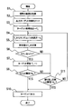
- FIG. 2 is a flow showing a part of processing in the in-vehicle device.
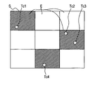
- FIG. 3 is an explanatory diagram illustrating an example of an evaluation value of a target candidate.
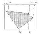
- FIG. 4 is an explanatory diagram illustrating another example of the evaluation value of the target candidate.
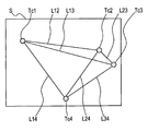
- FIG. 5 is an explanatory diagram illustrating still another example of the evaluation value of the target candidate.
- the in-vehicle device shown in FIG. 1 is configured around an ECU 1, and a line-of-sight measurement unit 3, a display 5, and an external camera 7 are connected to the ECU 1.
- the line-of-sight measurement unit 3 is a known unit that detects the line of sight of the driver.
- the display device 5 is a well-known device that is also used as a display screen of a car navigation device.
- the external camera 7 captures an image in front of the vehicle, and is a well-known camera used for a driving recorder, for example.
- FIG. 2 is a flowchart showing processing executed by the CPU built in the ECU 1 based on a program stored in a ROM also built in the ECU 1.
- This process is a process that is periodically and repeatedly executed during the operation of the line-of-sight measurement unit 3.
- This process is a process for setting the following target for correcting (calibrating) the line-of-sight measurement unit 3. That is, when a target is set, a shift between the position detected by the line-of-sight measuring unit 3 as the center of the driver's line of sight when it is estimated that the driver is gazing at the target and the position of the target is the line of sight. The correction is performed assuming that the detection error is detected by the measurement unit 3.
- the range of the visual field of the driver is acquired in S1 (S represents a step: the same applies hereinafter).
- the visual field referred to here indicates a range narrower than the visual field in the medical sense, and indicates a visual line range in which the visual line (center of the visual line) of the subject (driver) moves.
- Various methods for obtaining such a field of view range are conceivable. For example, in a situation where it is estimated that the driver is looking at the display 5, the screen S (see FIG. 3) of the display 5 is the range of the field of view. May be obtained as Further, in a situation where it is estimated that the driver is driving the vehicle, the shooting range of the external camera 7 may be acquired as the field of view.
- the target that has been output (set) is initialized.
- a plurality of points (>> N >> 1) as target candidates are extracted from the range of the visual field acquired in S1, and a set of the points is defined as T C.
- N points are randomly selected from T C extracted in S3, and a set of the points (candidate points) is set as a candidate point set T L.
- the evaluation value E (T L ) for the candidate point set T L is calculated by the following equation (1), for example.
- E (T L ) E S (T L ) + E A (T L ) + E C (T L ) (1)
- the evaluation value E S (T L ) is an index representing the degree of dispersion of candidate points with respect to the entire field of view, and is calculated as follows, for example.
- the evaluation value E S (T L ) calculated in this way may be normalized by dividing by the number of candidate points Tc1 to Tc4.
- FIG. 4 is a diagram illustrating another calculation method of the evaluation value E S (T L ).
- a convex hull C as a convex polygon that encompasses the entire candidate points Tc1 to Tc4 is assumed, and the area of the convex hull C is calculated as the evaluation value E S (T L ).
- the evaluation value E S (T L ) in Expression (1) may be calculated by a method other than these, or a value obtained by combining the calculated values obtained by the respective methods may be employed.
- the evaluation value E A (T L ) is an index indicating the ease of attention of candidate points, and is calculated as follows, for example.
- a saliency map is created based on the visual characteristics, and a value obtained by summing the saliency of each candidate point can be set as the evaluation value E A (T L ).
- the calculation of such saliency is, for example, Itti, L., Koch, C., & Niebur, E. 1998.
- the above-mentioned paper has a description that the optic nerve reacts greatly (that is, the degree of saliency is high) in a region where the difference in brightness, hue, direction, etc. is large.
- the saliency of each candidate point may be calculated including dynamic elements such as blinking light, or may be calculated based only on the dynamic elements.
- the area of a triangle formed by selecting any three of the candidate points Tc1 to Tc4 may be calculated, and the sum thereof may be used as the evaluation value E C (T L ). Furthermore, the evaluation value E C (T L ) calculated by these methods may be normalized by dividing by the number of line segments or the number of candidate points. The evaluation value E C (T L ) may be calculated by a method other than the above.
- the candidate point set T L is provisionally set (updated) as a target set T including N points of targets.
- the candidate point set T L is appropriately used as the target set T. It is evaluated. For this reason, the candidate point set T L can be appropriately evaluated regardless of the video entering the eyes of the driver. For example, even when the display image on the display device 5 is edited into an image that is not planned by the program creator, such as when a moving image is inserted in part, the information on the edited image is stored by the ECU 1. To be acquired. Therefore, the ECU 1 can appropriately calculate the evaluation value E (T L ) for the selected candidate point set T L.
- the target may be set to the image captured by the external camera 7.
- the shooting range of the external camera 7 is set as the field of view
- the target is set in the field of view as described above.
- the candidate point set on the blue signboard (guidance sign) on the road may be determined to be a candidate point that is likely to be noticed (that is, has a high evaluation value E A (T L )).
- candidate points that are likely to be noticed include other signs such as speed limits, signals (especially when the color changes), signals of the vehicle ahead, Examples include brake lamps, pedestrians, bicycles, road obstacles, and curve mirrors.
- the ECU 1 corresponds to an example of a line-of-sight range estimation unit, a candidate point extraction unit, a candidate point evaluation unit, and a target setting unit, and is an example of a target setting device including these four units.
- the line-of-sight measurement unit 3 corresponds to an example of a line-of-sight detection unit
- the display 5 corresponds to an example of a display unit
- the external camera 7 corresponds to an example of an imaging unit.
- S1 is an example of a line-of-sight range estimation unit
- S3 and S4 are examples of a candidate point extraction unit
- S5 is an example of a candidate point evaluation unit
- S6 to S11 are examples of a target setting unit.
- the target setting device is not limited to the embodiment, and can be implemented in various forms without departing from the gist of the present disclosure.
- the evaluation value E (T L ) calculated by the expression (1) is the evaluation value E S (T L ), E A (T L ), E C (T L ) corresponding to each index described above. It may be calculated without any one of the above.
- one of the indices is the degree of dispersion of the candidate points constituting the candidate point set with respect to the entire visual field range as in the evaluation value E S (T L )
- the following effects are produced. . That is, when a plurality of targets are set evenly distributed over the entire field of view, even if the detection error of the line-of-sight measuring unit 3 is different in each part of the field of view, the detection error is detected for each evenly distributed target. Can be sought. Therefore, if each candidate point constituting a candidate point set evaluated as having a high degree of dispersion with respect to the entire visual field range is set as a target, the visual line measurement unit 3 is appropriately corrected over a wide range in the visual field range. Can do.
- the process of correcting the gaze measuring unit 3 by estimating that the driver is gazing at the target can be executed more frequently. Also, the time for which the target is actually watched is long. Therefore, if a candidate point evaluated as being easily attracted attention is set as a target, the line-of-sight measurement unit 3 can be corrected more accurately.
- the candidate points are extracted and evaluated one by one.
- One target may be set based on the evaluation result.
- the target setting device is not limited to the in-vehicle device, and can be applied to various devices such as a personal computer.
- one of the plurality of indices is a degree of dispersion of the candidate points constituting the candidate point set with respect to the entire line-of-sight range. It may be.
- a plurality of targets are set to be evenly distributed over the entire line-of-sight range, even when the detection error of the line-of-sight detection unit is different in each part of the line-of-sight range, the detection error can be obtained for each evenly distributed target.
- the line-of-sight detection unit can be appropriately corrected over a wide range in the line-of-sight range. .
- the candidate point extraction unit extracts a candidate point set including a plurality of candidate points
- one of the plurality of indices is difficult to be confused between the candidate points constituting the candidate point set. There may be. Even if multiple targets are set, if there is a target that is not easily confused (e.g., easily confused), such as if the targets are close to each other or exist on the same line, the target gazes at which target It may not be possible to accurately estimate whether or not
- it is difficult to confuse each candidate point it can be estimated more accurately which target the subject is gazing at, and the line-of-sight detection unit can be corrected more satisfactorily.
- one of the plurality of indices may be the ease of attention of candidate points.
- the process of correcting the gaze detection unit by estimating that the subject is gazing at the target can be executed more frequently.
- the time for which the target is actually watched is long. Therefore, if a candidate point evaluated as being easily attracted attention is set as a target, the line-of-sight detection unit can be corrected more accurately.
- each step is expressed as, for example, S1. Further, each step can be divided into a plurality of sub-steps, while a plurality of steps can be combined into one step.
- embodiment, structure, and aspect of the target setting apparatus were illustrated, embodiment, structure, and aspect are not limited to each embodiment, each structure, and each aspect which were mentioned above.
- embodiments, configurations, and aspects obtained by appropriately combining technical sections described in different embodiments, configurations, and aspects are also included in the scope of the present embodiments, configurations, and aspects.
Landscapes
- Engineering & Computer Science (AREA)
- Theoretical Computer Science (AREA)
- General Engineering & Computer Science (AREA)
- Physics & Mathematics (AREA)
- General Physics & Mathematics (AREA)
- Human Computer Interaction (AREA)
- Health & Medical Sciences (AREA)
- Life Sciences & Earth Sciences (AREA)
- Combustion & Propulsion (AREA)
- Mechanical Engineering (AREA)
- Transportation (AREA)
- General Health & Medical Sciences (AREA)
- Ophthalmology & Optometry (AREA)
- Chemical & Material Sciences (AREA)
- Multimedia (AREA)
- Computer Vision & Pattern Recognition (AREA)
- Heart & Thoracic Surgery (AREA)
- Biomedical Technology (AREA)
- Medical Informatics (AREA)
- Molecular Biology (AREA)
- Surgery (AREA)
- Animal Behavior & Ethology (AREA)
- Public Health (AREA)
- Veterinary Medicine (AREA)
- Biophysics (AREA)
- Eye Examination Apparatus (AREA)
- Position Input By Displaying (AREA)
- Traffic Control Systems (AREA)
Abstract
ターゲット設定装置は、被験者の視線を検出する視線検出部(3)を補正するためのターゲットを設定する。ターゲット設定装置は、被験者の視線が移動する視線範囲を推定する視線範囲推定部(1,S1)と、視線範囲推定部(1,S1)が推定した視線範囲から、ターゲットの候補点(Tc)を抽出する候補点抽出部(1,S3,S4)と、候補点抽出部(1,S3,S4)が抽出した候補点のターゲットとしての適切さを複数の指標を用いて評価する候補点評価部(1,S5)と、候補点評価部(1,S5)が評価したターゲットとしての適切さに基づき、候補点をターゲットに設定するか否かを判断するターゲット設定部(1,S6~S11)と、を備える。
Description
本出願は、2014年6月11日に出願された日本国特許出願2014-120679号に基づくものであり、ここにその記載内容を参照により援用する。
本開示は、被験者の視線を検出する視線検出部を補正するためのターゲットを設定するターゲット設定装置に関する。
従来、被験者の視線を検出する視線検出部を備え、検出された視線に応じた制御を実行する装置が種々提案されている。例えば、文字が1つずつ表示された複数のカーソルをパーソナルコンピュータの入力ダイアログ画面に並べて表示し、特定のカーソルが注視されたときにそのカーソルに対応する文字入力が指示されたと判断する装置が提案されている(例えば特許文献1参照。)。
また、特許文献1に記載の構成では、各カーソルの中心にターゲットを設定して、視線検出部を自動的に補正している。すなわち、特定のカーソルが注視されたと視線検出部が推定したとき、当該視線検出部が視線の中心として検出した位置と、前記特定のカーソルの中心位置(ターゲット)とのずれが、視線検出部の検出誤差であるとして、前記補正に応用している。なお、特許文献1に記載の構成では、眼球回転角を検出する視線センサとその眼球回転角に対する処理とで視線検出部を形成し、前記ずれは、眼球回転角に対する処理がなされる際の補正データに反映される。前記検出誤差には、視線検出部自身に起因する誤差の他にも、被験者個人の眼球動作の特徴に起因する誤差も含まれている(以下同様)。
本願発明者は下記を見出した。特許文献1に記載の構成では、入力ダイアログ画面における予め設定された箇所に表示されるカーソルの中心に、前述のターゲットを設定している。このため、装置の設計者が当初想定していなかったような図柄及び配置の画面が使用される場合は、適切にターゲットを設定することができない。また、被験者が外などを見ているときにも、視線検出部による被験者の視線検出がなされる場合があり、そのような場合にも適切にターゲットが設定されるのが望ましい。
そこで、本開示は、被験者の目に入る映像の如何に関わらず、視線検出部を補正するためのターゲットを良好に設定可能なターゲット設定装置を、提供することを目的とする。
本開示の一態様に係るターゲット設定装置によれば、ターゲット設定装置は、被験者の視線を検出する視線検出部を補正するためのターゲットを設定する。ターゲットは、被験者が当該ターゲットを注視していると推定されるときに視線検出部が視線の中心として検出した位置と、ターゲットの位置とのずれが、視線検出部の検出誤差であるとして補正に応用される。ターゲット設定装置は、被験者の視線が移動する視線範囲を推定する視線範囲推定部と、視線範囲推定部が推定した視線範囲から、ターゲットの候補点を抽出する候補点抽出部と、候補点抽出部が抽出した候補点のターゲットとしての適切さを複数の指標を用いて評価する候補点評価部と、候補点評価部が評価したターゲットとしての適切さに基づき、候補点をターゲットに設定するか否かを判断するターゲット設定部と、を備える。
本開示のターゲット設定装置によれば、ターゲットの候補点を抽出し、その候補点を複数の指標を用いて評価している。このため、被験者の目に入る映像の如何に関わらず、被験者の視線が移動する視線範囲から抽出された候補点を前記複数の指標によって評価することができる。従って、被験者の目に入る映像の如何に関わらず、視線検出部を補正するためのターゲットを良好に設定することができる。
本開示についての上記および他の目的、特徴や利点は、添付の図面を参照した下記の詳細な説明から、より明確になる。添付図面において、
図1は、車載装置の構成を表すブロック図であり、
図2は、その車載装置における処理の一部を表すフローであり、
図3は、ターゲット候補の評価値の一例を表す説明図であり、
図4は、ターゲット候補の評価値の他の例を表す説明図であり、
図5は、ターゲット候補の評価値の更に他の例を表す説明図である。
[本実施形態の構成]
実施形態を図面と共に説明する。図1に示す車載装置は、ECU1を中心に構成され、当該ECU1には、視線計測部3と、表示器5と、外部カメラ7とが接続されている。視線計測部3は、ドライバの視線を検出する周知のものである。表示器5は、カーナビゲーション装置の表示画面等としても使用される周知のものである。外部カメラ7は、車両前方の映像を撮影するもので、例えばドライビングレコーダ等に使用される周知のものである。
実施形態を図面と共に説明する。図1に示す車載装置は、ECU1を中心に構成され、当該ECU1には、視線計測部3と、表示器5と、外部カメラ7とが接続されている。視線計測部3は、ドライバの視線を検出する周知のものである。表示器5は、カーナビゲーション装置の表示画面等としても使用される周知のものである。外部カメラ7は、車両前方の映像を撮影するもので、例えばドライビングレコーダ等に使用される周知のものである。
[実施形態における処理]
図2は、ECU1に内蔵されたCPUが、同じくECU1に内蔵されたROMに記憶されたプログラムに基づいて実行する処理を表すフローである。なお、この処理は、視線計測部3の動作中に定期的に繰り返して実行される処理である。この処理は、視線計測部3を補正(キャリブレーション)するための次のようなターゲットを設定するための処理である。すなわち、ターゲットが設定されると、ドライバが当該ターゲットを注視していると推定されるときに視線計測部3がドライバの視線の中心として検出した位置と、当該ターゲットの位置とのずれが、視線計測部3の検出誤差であるとして前記補正がなされる。
図2は、ECU1に内蔵されたCPUが、同じくECU1に内蔵されたROMに記憶されたプログラムに基づいて実行する処理を表すフローである。なお、この処理は、視線計測部3の動作中に定期的に繰り返して実行される処理である。この処理は、視線計測部3を補正(キャリブレーション)するための次のようなターゲットを設定するための処理である。すなわち、ターゲットが設定されると、ドライバが当該ターゲットを注視していると推定されるときに視線計測部3がドライバの視線の中心として検出した位置と、当該ターゲットの位置とのずれが、視線計測部3の検出誤差であるとして前記補正がなされる。
図2に示すように、この処理では、先ず、S1(Sはステップを表す:以下同様)にて、ドライバの視野の範囲が取得される。なお、ここでいう視野とは、医学的な意味での視野よりも狭い範囲を示しており、被験者(ドライバ)の視線(視線の中心)が移動する視線範囲を示している。このような視野の範囲の取得方法としては種々考えられるが、例えば、ドライバが表示器5を見ていると推定される状況の場合、表示器5の画面S(図3参照)が視野の範囲として取得されてもよい。また、ドライバが車両の運転中であると推定される状況の場合、外部カメラ7の撮影範囲が視野の範囲として取得されてもよい。
続くS2では、それまで出力(設定)されていたターゲットが初期化される。S3では、S1にて取得された視野の範囲からターゲット候補となる点が複数(≫N≫1)抽出されて、その点の集合がTC とされる。S4では、S3にて抽出されたTC からランダムにN点が選択され、その点(候補点)の集合が候補点組TL とされる。更に、S5では、その候補点組TL に対する評価値E(TL )が、例えば次の式(1)により計算される。
E(TL )=ES (TL )+EA (TL )+EC (TL ) ………(1)
なお、式(1)において、評価値ES (TL )は前記視野の範囲全体に対する候補点の分散度合いを表す指標であり、例えば次のようにして計算される。図3の例では、表示器5の画面Sを3×3に9等分して得られる各エリアEのうち、内部に候補点Tc1~Tc4が存在するエリアEがいくつあるか、換言すれば、各候補点Tc1~Tc4による画面カバー率がどの程度かを計算して、評価値ES (TL )としている。なお、このようにして計算された評価値ES (TL )は、候補点Tc1~Tc4の数で割られることによって正規化されてもよい。
なお、式(1)において、評価値ES (TL )は前記視野の範囲全体に対する候補点の分散度合いを表す指標であり、例えば次のようにして計算される。図3の例では、表示器5の画面Sを3×3に9等分して得られる各エリアEのうち、内部に候補点Tc1~Tc4が存在するエリアEがいくつあるか、換言すれば、各候補点Tc1~Tc4による画面カバー率がどの程度かを計算して、評価値ES (TL )としている。なお、このようにして計算された評価値ES (TL )は、候補点Tc1~Tc4の数で割られることによって正規化されてもよい。
図4は、評価値ES (TL )の他の計算方法を表す図である。図4の例では、候補点Tc1~Tc4の全体を包含する凸多角形としての凸包Cを想定し、その凸包Cの面積を計算して評価値ES (TL )としている。式(1)における評価値ES (TL )は、これら以外の方法で計算されてもよく、各方法による計算値を組み合わせた値が採用されてもよい。
式(1)において評価値EA (TL )は、候補点の注目されやすさを表す指標であり、例えば次のように計算される。視覚特性に基づき顕著性マップを作成し、各候補点の顕著度を合計した値を、評価値EA (TL )とすることができる。なお、このような顕著度の計算は、例えば、Itti, L., Koch, C., & Niebur, E. 1998. A Model of Saliency-Based Visual Attention for Rapid Scene Analysis. IEEE Transactions on Pattern Analysis and Machine Intelligence等に詳しいので、ここでは詳述しない。前記論文には、輝度,色相,方向等について周囲との差が大きい領域に対して、視神経が大きく反応する(すなわち顕著度が高い)主旨の記述がある。また、各候補点の顕著度は、光の点滅などの動的要素も含めて計算されてもよく、動的要素のみに基づいて計算されてもよい。
式(1)において評価値EC (TL )は、候補点の混同されにくさを表す指標であり、例えば次のように計算される。2つの候補点(Tc1~Tc4のいずれか2つ)の距離が離れているほど、当該2つの候補点は混同されにくい。そこで、図5に示すように、候補点Tcmと候補点Tcnとを結ぶ線分がLmn(m,n=1,2,3,または4)とされ、各線分L12~L34の長さの総和が混同されにくさを表す評価値EC (TL )とされてもよい。また、3つの候補点が同一直線上に並んでいる場合も混同されやすい。そこで、候補点Tc1~Tc4の任意の3点を選んで形成される三角形の面積がそれぞれ計算され、その総和が評価値EC (TL )とされてもよい。更に、それらの方法で計算された評価値EC (TL )は、線分の数または候補点の数で割られて正規化されてもよい。評価値EC (TL )は、前記以外の方法で計算されてもよい。
図2に戻って、S5にてこのように候補点組TL に対する評価値E(TL )が計算されると、S6にて、既に計算されている他の候補点組TL に対する評価値E(TL )の最高値E(T)以上であるか否かが判断される。E(TL )≧E(T)の場合は(S6:YES)、処理はS7へ移行する。なお、図2の処理が開始された後に初めてS6の処理が実行されたときには、E(T)の値が0にリセットされているので、S4にて選択された候補点組TL の如何に関わらずE(TL )≧E(T)と判断されて(S6:YES)、処理はS7へ移行する。
S7では、候補点組TL がN点のターゲットからなるターゲット組Tとして仮に設定(更新)される。続くS8では、そのターゲット組Tの評価値E(T)、すなわち、前述の評価値E(TL )が、閾値THE 以上であるか否かが判断される。E(T)≧THE の場合は(S8:YES)、処理はS10へ移行し、そのターゲット組Tが視線計測部3の補正用ターゲットとして出力されて処理が一旦終了する。
すると、ドライバがターゲット組Tに属するいずれかの点(ターゲット)を注視していると推定されるときに、視線計測部3がドライバの視線の中心として検出した位置と、当該ターゲットの位置とのずれに基づいて視線計測部3の検出誤差が補正される。このような処理(キャリブレーション)は、ドライバが表示器5を無意識に見ている間に、図2とは別の処理によって実行される。また、このようなキャリブレーションの処理は周知であるので、ここでは詳述しない。
一方、評価値E(TL )が閾値THE 未満である場合(S8:NO)、または、候補点組TL に対する評価値E(TL )がそれまでに計算されている評価値E(T)未満であった場合は(S6:NO)、処理はS11へ移行する。S11では、S4~S5の処理の繰り返し回数Lが閾値THL 以上であるか否かが判断される。繰り返し回数Lが閾値THL 未満の場合は(S11:NO)、処理は前述のS4へ移行し、繰り返し回数Lが閾値THL 以上である場合は(S11:YES)、処理は前述のS10へ移行する。すなわち、候補点組TL の選択(S4)がTHL 回やり直されても評価値E(TL )が閾値THE 以上となる候補点組TL がなかった場合は(S8:NO、S11:YES)、それまでに評価値E(TL )が最高であった候補点組TL がターゲット組Tとして設定される(S10)。
[本実施形態の効果及び変形例]
このように、本実施形態では、候補点組TL を選択して複数の指標を用いた評価値E(TL )を計算することによって、当該候補点組TL のターゲット組Tとしての適切さを評価している。このため、ドライバの目に入る映像の如何に関わらず、前記候補点組TL を適切に評価することができる。例えば、表示器5の表示画像が、一部に動画が挿入されるなど、プログラムの制作者が予定していなかったような画像に編集された場合にも、編集後の画像の情報はECU1によって取得される。このため、ECU1は、選択された候補点組TL に対して適切に評価値E(TL )を計算することができる。
このように、本実施形態では、候補点組TL を選択して複数の指標を用いた評価値E(TL )を計算することによって、当該候補点組TL のターゲット組Tとしての適切さを評価している。このため、ドライバの目に入る映像の如何に関わらず、前記候補点組TL を適切に評価することができる。例えば、表示器5の表示画像が、一部に動画が挿入されるなど、プログラムの制作者が予定していなかったような画像に編集された場合にも、編集後の画像の情報はECU1によって取得される。このため、ECU1は、選択された候補点組TL に対して適切に評価値E(TL )を計算することができる。
また、図3~図5の例では、表示器5の画面Sに表示された画像にターゲットを設定する場合を示しているが、外部カメラ7が撮影した画像にターゲットが設定されてもよい。その場合、S1では、外部カメラ7の撮影範囲が視野の範囲とされ、その視野の範囲に前述のようにターゲットが設定される。そして、その場合、路上の青看板(案内標識)に設定された候補点が、注目されやすい(すなわち、評価値EA (TL )の高い)候補点であると判断されてもよい。外部カメラ7が撮影した画像にターゲットが設定される場合、注目されやすい候補点としては、案内標識以外にも、速度制限等の他の標識や、信号(特に色の変化時)、前方車両のブレーキランプ、歩行者、自転車、路上障害物、カーブミラー等が挙げられる。
なお、前記実施形態において、ECU1が、視線範囲推定部,候補点抽出部,候補点評価部,及びターゲット設定部の一例に相当し、かつ、それら4つの部を備えたターゲット設定装置の一例に相当する。また、視線計測部3が視線検出部の一例に、表示器5が表示部の一例に、外部カメラ7が撮影部の一例に、それぞれ相当する。また、ECU1の処理のうち、S1が視線範囲推定部の一例に、S3及びS4が候補点抽出部の一例に、S5が候補点評価部の一例に、S6~S11がターゲット設定部の一例に、それぞれ相当する。
また、ターゲット設定装置は実施形態に何ら限定されるものではなく、本開示の要旨を逸脱しない範囲で種々の形態で実施することができる。例えば、式(1)で計算される評価値E(TL )は、前述した各指標に対応する評価値ES (TL ),EA (TL ),EC (TL )のうちのいずれか1つを欠いて計算されてもよい。
ただし、指標のうちの1つが、前述の評価値ES (TL )のように、候補点組を構成する各候補点の視野範囲全体に対する分散度合いである場合、次のような効果が生じる。すなわち、複数のターゲットが視野の範囲全体に均等に分散して設定された場合は、視野の範囲の各部で視線計測部3の検出誤差が異なる場合でも、均等に分散したターゲット毎に検出誤差を求めることができる。従って、視野範囲全体に対する分散度合いが高いと評価された候補点組を構成する各候補点がターゲットとして設定されれば、視野の範囲における広い範囲に亘って適切に視線計測部3を補正することができる。
また、指標のうちの1つが評価値EC (TL )のように各候補点同士の混同されにくさである場合、次のような効果が生じる。複数のターゲットが設定されたとしても、ターゲット同士が近接しているとか同一直線上に存在するとかいった混同されにくさの低い(混同されやすい)ターゲットが存在すると、ドライバがどのターゲットを注視しているのか正確に推定できない場合がある。これに対して、各候補点同士の混同されにくさが高い場合、ドライバがどのターゲットを注視しているのかをより正確に推定することができ視線計測部3を一層良好に補正することができる。
また、指標のうちの1つが評価値EA (TL )のように候補点の注目されやすさである場合、次のような効果が生じる。視野の範囲の中でも注目されやすい点は、ドライバが実際にその点を注視する機会が多い。そのような点にターゲットが設定されていると、当該ターゲットをドライバが注視していると推定して視線計測部3を補正する処理は、より頻繁に実行されることができる。また、そのターゲットが実際に注視される時間も長い。従って、注目されやすさが高いと評価された候補点がターゲットとして設定されれば、視線計測部3を一層正確に補正することができる。
そして、この注目されやすさのように、単一の候補点に対して評価値を計算することが可能な指標のみが複数用いられる場合は、候補点は1点ずつ抽出されて評価され、その評価結果に基づいて1点のターゲットが設定されてもよい。また、ターゲット設定装置は車載装置に限定されるわけではなく、パーソナルコンピュータ等の種々の装置に適用することができる。
なお、前記候補点抽出部が複数の候補点からなる候補点組を抽出する場合、前記複数の指標のうちの1つは、前記候補点組を構成する各候補点の視線範囲全体に対する分散度合いであってもよい。複数のターゲットが視線範囲全体に均等に分散して設定された場合は、視線範囲の各部で視線検出部の検出誤差が異なる場合でも、均等に分散したターゲット毎に検出誤差を求めることができる。従って、視野範囲全体に対する分散度合いが高いと評価された候補点組を構成する各候補点がターゲットとして設定されれば、視線範囲における広い範囲に亘って適切に視線検出部を補正することができる。
また、前記候補点抽出部が複数の候補点からなる候補点組を抽出する場合、前記複数の指標のうちの1つは、前記候補点組を構成する各候補点同士の混同されにくさであってもよい。複数のターゲットが設定されたとしても、ターゲット同士が近接しているとか同一直線上に存在するとかいった混同されにくさの低い(混同されやすい)ターゲットが存在すると、被験者がどのターゲットを注視しているのか正確に推定できない場合がある。これに対して、各候補点同士の混同されにくさが高い場合、被験者がどのターゲットを注視しているのかをより正確に推定することができ視線検出部を一層良好に補正することができる。
また、前記複数の指標のうちの1つは、候補点の注目されやすさであってもよい。視線範囲の中でも注目されやすい点は、被験者が実際にその点を注視する機会が多い。そのような点にターゲットが設定されていると、当該ターゲットを被験者が注視していると推定して視線検出部を補正する処理は、より頻繁に実行されることができる。また、そのターゲットが実際に注視される時間も長い。従って、注目されやすさが高いと評価された候補点がターゲットとして設定されれば、視線検出部を一層正確に補正することができる。
この出願に記載されるフローチャート、あるいは、フローチャートの処理は、複数のステップ(あるいはセクションと言及される)から構成され、各ステップは、たとえば、S1と表現される。さらに、各ステップは、複数のサブステップに分割されることができる、一方、複数のステップが合わさって一つのステップにすることも可能である。
以上、ターゲット設定装置の実施形態、構成、態様を例示したが、実施形態、構成、態様は、上述した各実施形態、各構成、各態様に限定されるものではない。例えば、異なる実施形態、構成、態様にそれぞれ記載された技術的部を適宜組み合わせて得られる実施形態、構成、態様についても本実施形態、構成、態様の範囲に含まれる。
Claims (7)
- 被験者の視線を検出する視線検出部(3)を補正するためのターゲットを設定するターゲット設定装置であって、
前記ターゲットは、前記被験者が当該ターゲットを注視していると推定されるときに前記視線検出部(3)が前記視線の中心として検出した位置と、前記ターゲットの位置とのずれが、前記視線検出部(3)の検出誤差であるとして前記補正に応用されるものであり、
前記被験者の視線が移動する視線範囲を推定する視線範囲推定部(1,S1)と、
前記視線範囲推定部(1,S1)が推定した視線範囲から、ターゲットの候補点(Tc)を抽出する候補点抽出部(1,S3,S4)と、
前記候補点抽出部(1,S3,S4)が抽出した候補点のターゲットとしての適切さを複数の指標を用いて評価する候補点評価部(1,S5)と、
前記候補点評価部(1,S5)が評価したターゲットとしての適切さに基づき、前記候補点をターゲットに設定するか否かを判断するターゲット設定部(1,S6~S11)と、
を備えるターゲット設定装置。 - 前記候補点抽出部(1,S3,S4)は、複数の候補点を含む候補点組を抽出し、
前記候補点評価部(1,S5)は、前記候補点抽出部(1,S3,S4)が抽出した前記候補点組に対して、複数のターゲットを含むターゲット組(T)としての適切さを評価し、
前記ターゲット設定部(1,S6~S11)は、前記候補点評価部(1,S5)が評価したターゲット組としての適切さに基づき、前記候補点組を構成する各候補点をターゲットに設定するか否かを判断する請求項1に記載のターゲット設定装置。 - 前記複数の指標のうちの1つは、前記候補点組を構成する各候補点の視線範囲全体に対する分散度合いである請求項2に記載のターゲット設定装置。
- 前記複数の指標のうちの1つは、前記候補点組を構成する各候補点同士の混同されにくさである請求項2または3に記載のターゲット設定装置。
- 前記複数の指標のうちの1つは、候補点の注目されやすさである請求項1~4のいずれか1項に記載のターゲット設定装置。
- 前記視線範囲推定部(1,S1)は、前記被験者に向けて画像を表示する表示部(5)の画面(S)を、視線範囲として推定し、
前記候補点抽出部(1,S3,S4)は、前記画面(S)上の点を前記候補点として抽出し、
前記候補点評価部(1,S5)は、前記画面(S)に表示される画像の情報に基づいて前記適切さを評価する請求項1~5のいずれか1項に記載のターゲット設定装置。 - 前記被験者は車両のドライバであり、
前記視線範囲推定部(1,S1)は、前記車両の前方を撮影する撮影部(7)の撮影範囲を視線範囲として推定し、
前記候補点抽出部(1,S3,S4)は、前記撮影部(7)が撮影した画像上の点を前記候補点として抽出し、
前記候補点評価部(1,S5)は、前記撮影部(7)が撮影した画像に基づいて前記適切さを評価する請求項1~5のいずれか1項に記載のターゲット設定装置。
Priority Applications (2)
| Application Number | Priority Date | Filing Date | Title |
|---|---|---|---|
| US15/310,853 US9996172B2 (en) | 2014-06-11 | 2015-04-07 | Target setting apparatus |
| DE112015002751.3T DE112015002751T5 (de) | 2014-06-11 | 2015-04-07 | Zieleinstellvorrichtung |
Applications Claiming Priority (2)
| Application Number | Priority Date | Filing Date | Title |
|---|---|---|---|
| JP2014120679A JP6233199B2 (ja) | 2014-06-11 | 2014-06-11 | ターゲット設定装置 |
| JP2014-120679 | 2014-06-11 |
Publications (1)
| Publication Number | Publication Date |
|---|---|
| WO2015190022A1 true WO2015190022A1 (ja) | 2015-12-17 |
Family
ID=54833141
Family Applications (1)
| Application Number | Title | Priority Date | Filing Date |
|---|---|---|---|
| PCT/JP2015/001951 Ceased WO2015190022A1 (ja) | 2014-06-11 | 2015-04-07 | ターゲット設定装置 |
Country Status (4)
| Country | Link |
|---|---|
| US (1) | US9996172B2 (ja) |
| JP (1) | JP6233199B2 (ja) |
| DE (1) | DE112015002751T5 (ja) |
| WO (1) | WO2015190022A1 (ja) |
Families Citing this family (1)
| Publication number | Priority date | Publication date | Assignee | Title |
|---|---|---|---|---|
| CN116807387B (zh) * | 2023-06-13 | 2026-04-21 | 杭州海康威视数字技术股份有限公司 | 一种视线估计方法、装置及设备 |
Citations (2)
| Publication number | Priority date | Publication date | Assignee | Title |
|---|---|---|---|---|
| JP2013196359A (ja) * | 2012-03-19 | 2013-09-30 | Honda Motor Co Ltd | 運転支援装置 |
| JP2014071779A (ja) * | 2012-09-28 | 2014-04-21 | Jvc Kenwood Corp | 診断支援装置および診断支援方法 |
Family Cites Families (5)
| Publication number | Priority date | Publication date | Assignee | Title |
|---|---|---|---|---|
| JP2000010723A (ja) | 1998-06-18 | 2000-01-14 | Mr System Kenkyusho:Kk | 視線センサのキャリブレーション方法、視線入力装置およびプログラム記憶媒体 |
| US7492957B1 (en) * | 2005-08-29 | 2009-02-17 | Symantec Corporation | Using run length encoding to detect target images |
| JP5664064B2 (ja) | 2010-09-22 | 2015-02-04 | 富士通株式会社 | 視線検出装置および補正係数算出プログラム |
| JP5993233B2 (ja) * | 2012-07-11 | 2016-09-14 | オリンパス株式会社 | 画像処理装置及び画像処理方法 |
| JP6123180B2 (ja) * | 2012-07-18 | 2017-05-10 | 株式会社ニコン | 表示装置 |
-
2014
- 2014-06-11 JP JP2014120679A patent/JP6233199B2/ja not_active Expired - Fee Related
-
2015
- 2015-04-07 US US15/310,853 patent/US9996172B2/en active Active
- 2015-04-07 DE DE112015002751.3T patent/DE112015002751T5/de not_active Withdrawn
- 2015-04-07 WO PCT/JP2015/001951 patent/WO2015190022A1/ja not_active Ceased
Patent Citations (2)
| Publication number | Priority date | Publication date | Assignee | Title |
|---|---|---|---|---|
| JP2013196359A (ja) * | 2012-03-19 | 2013-09-30 | Honda Motor Co Ltd | 運転支援装置 |
| JP2014071779A (ja) * | 2012-09-28 | 2014-04-21 | Jvc Kenwood Corp | 診断支援装置および診断支援方法 |
Also Published As
| Publication number | Publication date |
|---|---|
| US20170108940A1 (en) | 2017-04-20 |
| DE112015002751T5 (de) | 2017-03-23 |
| JP6233199B2 (ja) | 2017-11-22 |
| US9996172B2 (en) | 2018-06-12 |
| JP2016001379A (ja) | 2016-01-07 |
Similar Documents
| Publication | Publication Date | Title |
|---|---|---|
| CN114026611B (zh) | 使用热图检测驾驶员注意力 | |
| US11157753B2 (en) | Road line detection device and road line detection method | |
| US10204277B2 (en) | Electronic device, traveling lane identifying system, and traveling lane identifying method | |
| JP6552729B2 (ja) | 異なる分解能を有するセンサーの出力を融合するシステム及び方法 | |
| CN110060297B (zh) | 信息处理装置、系统、信息处理方法和存储介质 | |
| GB2584033A (en) | Object tracking in zoomed video | |
| US20180304898A1 (en) | Road surface state determination apparatus, imaging apparatus, imaging system, and road surface state determination method | |
| CN107203044A (zh) | 车辆用显示装置 | |
| EP4151951B1 (en) | Vehicle localization method and device, electronic device and storage medium | |
| JP4988781B2 (ja) | 車両の周辺監視装置 | |
| WO2011108218A1 (ja) | 車両の周辺監視装置 | |
| CN106660495A (zh) | 车辆用显示装置以及车辆用显示方法 | |
| US20160358028A1 (en) | Visual line detection device and visual line detection method | |
| CN111989915B (zh) | 用于图像中的环境的自动视觉推断的方法、介质、及系统 | |
| JP6277933B2 (ja) | 表示制御装置、表示システム | |
| JP2009040108A (ja) | 画像表示制御装置及び画像表示制御システム | |
| WO2017169273A1 (ja) | 情報処理装置、情報処理方法、及びプログラム | |
| WO2015186294A1 (ja) | 車載画像処理装置 | |
| CN117727011A (zh) | 基于图像融合的目标识别方法、装置、设备及存储介质 | |
| WO2017169272A1 (ja) | 情報処理装置、情報処理方法、及びプログラム | |
| WO2019026747A1 (ja) | 車両用拡張現実画像表示装置 | |
| WO2020230418A1 (ja) | 表示装置 | |
| WO2020213088A1 (ja) | 表示制御装置、表示制御方法、プログラム、ならびに、非一時的なコンピュータ読取可能な情報記録媒体 | |
| JP2018045437A (ja) | 虹彩検出装置、虹彩検出方法、およびプログラム | |
| EP3396620B1 (en) | Display control device and display control method |
Legal Events
| Date | Code | Title | Description |
|---|---|---|---|
| 121 | Ep: the epo has been informed by wipo that ep was designated in this application |
Ref document number: 15806689 Country of ref document: EP Kind code of ref document: A1 |
|
| WWE | Wipo information: entry into national phase |
Ref document number: 15310853 Country of ref document: US |
|
| WWE | Wipo information: entry into national phase |
Ref document number: 112015002751 Country of ref document: DE |
|
| 122 | Ep: pct application non-entry in european phase |
Ref document number: 15806689 Country of ref document: EP Kind code of ref document: A1 |