WO2015186384A1 - Endoscope system - Google Patents
Endoscope system Download PDFInfo
- Publication number
- WO2015186384A1 WO2015186384A1 PCT/JP2015/056053 JP2015056053W WO2015186384A1 WO 2015186384 A1 WO2015186384 A1 WO 2015186384A1 JP 2015056053 W JP2015056053 W JP 2015056053W WO 2015186384 A1 WO2015186384 A1 WO 2015186384A1
- Authority
- WO
- WIPO (PCT)
- Prior art keywords
- light
- value
- unit
- output
- endoscope
- Prior art date
Links
Images


Classifications
-
- A—HUMAN NECESSITIES
- A61—MEDICAL OR VETERINARY SCIENCE; HYGIENE
- A61B—DIAGNOSIS; SURGERY; IDENTIFICATION
- A61B1/00—Instruments for performing medical examinations of the interior of cavities or tubes of the body by visual or photographical inspection, e.g. endoscopes; Illuminating arrangements therefor
- A61B1/00002—Operational features of endoscopes
- A61B1/00004—Operational features of endoscopes characterised by electronic signal processing
- A61B1/00009—Operational features of endoscopes characterised by electronic signal processing of image signals during a use of endoscope
-
- A—HUMAN NECESSITIES
- A61—MEDICAL OR VETERINARY SCIENCE; HYGIENE
- A61B—DIAGNOSIS; SURGERY; IDENTIFICATION
- A61B1/00—Instruments for performing medical examinations of the interior of cavities or tubes of the body by visual or photographical inspection, e.g. endoscopes; Illuminating arrangements therefor
- A61B1/00002—Operational features of endoscopes
- A61B1/00004—Operational features of endoscopes characterised by electronic signal processing
-
- A—HUMAN NECESSITIES
- A61—MEDICAL OR VETERINARY SCIENCE; HYGIENE
- A61B—DIAGNOSIS; SURGERY; IDENTIFICATION
- A61B1/00—Instruments for performing medical examinations of the interior of cavities or tubes of the body by visual or photographical inspection, e.g. endoscopes; Illuminating arrangements therefor
- A61B1/00163—Optical arrangements
- A61B1/00165—Optical arrangements with light-conductive means, e.g. fibre optics
-
- A—HUMAN NECESSITIES
- A61—MEDICAL OR VETERINARY SCIENCE; HYGIENE
- A61B—DIAGNOSIS; SURGERY; IDENTIFICATION
- A61B1/00—Instruments for performing medical examinations of the interior of cavities or tubes of the body by visual or photographical inspection, e.g. endoscopes; Illuminating arrangements therefor
- A61B1/00163—Optical arrangements
- A61B1/00172—Optical arrangements with means for scanning
-
- A—HUMAN NECESSITIES
- A61—MEDICAL OR VETERINARY SCIENCE; HYGIENE
- A61B—DIAGNOSIS; SURGERY; IDENTIFICATION
- A61B1/00—Instruments for performing medical examinations of the interior of cavities or tubes of the body by visual or photographical inspection, e.g. endoscopes; Illuminating arrangements therefor
- A61B1/04—Instruments for performing medical examinations of the interior of cavities or tubes of the body by visual or photographical inspection, e.g. endoscopes; Illuminating arrangements therefor combined with photographic or television appliances
- A61B1/042—Instruments for performing medical examinations of the interior of cavities or tubes of the body by visual or photographical inspection, e.g. endoscopes; Illuminating arrangements therefor combined with photographic or television appliances characterised by a proximal camera, e.g. a CCD camera
-
- A—HUMAN NECESSITIES
- A61—MEDICAL OR VETERINARY SCIENCE; HYGIENE
- A61B—DIAGNOSIS; SURGERY; IDENTIFICATION
- A61B1/00—Instruments for performing medical examinations of the interior of cavities or tubes of the body by visual or photographical inspection, e.g. endoscopes; Illuminating arrangements therefor
- A61B1/06—Instruments for performing medical examinations of the interior of cavities or tubes of the body by visual or photographical inspection, e.g. endoscopes; Illuminating arrangements therefor with illuminating arrangements
- A61B1/0638—Instruments for performing medical examinations of the interior of cavities or tubes of the body by visual or photographical inspection, e.g. endoscopes; Illuminating arrangements therefor with illuminating arrangements providing two or more wavelengths
-
- A—HUMAN NECESSITIES
- A61—MEDICAL OR VETERINARY SCIENCE; HYGIENE
- A61B—DIAGNOSIS; SURGERY; IDENTIFICATION
- A61B1/00—Instruments for performing medical examinations of the interior of cavities or tubes of the body by visual or photographical inspection, e.g. endoscopes; Illuminating arrangements therefor
- A61B1/06—Instruments for performing medical examinations of the interior of cavities or tubes of the body by visual or photographical inspection, e.g. endoscopes; Illuminating arrangements therefor with illuminating arrangements
- A61B1/0655—Control therefor
-
- A—HUMAN NECESSITIES
- A61—MEDICAL OR VETERINARY SCIENCE; HYGIENE
- A61B—DIAGNOSIS; SURGERY; IDENTIFICATION
- A61B1/00—Instruments for performing medical examinations of the interior of cavities or tubes of the body by visual or photographical inspection, e.g. endoscopes; Illuminating arrangements therefor
- A61B1/06—Instruments for performing medical examinations of the interior of cavities or tubes of the body by visual or photographical inspection, e.g. endoscopes; Illuminating arrangements therefor with illuminating arrangements
- A61B1/07—Instruments for performing medical examinations of the interior of cavities or tubes of the body by visual or photographical inspection, e.g. endoscopes; Illuminating arrangements therefor with illuminating arrangements using light-conductive means, e.g. optical fibres
-
- G—PHYSICS
- G02—OPTICS
- G02B—OPTICAL ELEMENTS, SYSTEMS OR APPARATUS
- G02B23/00—Telescopes, e.g. binoculars; Periscopes; Instruments for viewing the inside of hollow bodies; Viewfinders; Optical aiming or sighting devices
- G02B23/24—Instruments or systems for viewing the inside of hollow bodies, e.g. fibrescopes
- G02B23/2407—Optical details
- G02B23/2461—Illumination
- G02B23/2469—Illumination using optical fibres
-
- G—PHYSICS
- G02—OPTICS
- G02B—OPTICAL ELEMENTS, SYSTEMS OR APPARATUS
- G02B23/00—Telescopes, e.g. binoculars; Periscopes; Instruments for viewing the inside of hollow bodies; Viewfinders; Optical aiming or sighting devices
- G02B23/24—Instruments or systems for viewing the inside of hollow bodies, e.g. fibrescopes
- G02B23/26—Instruments or systems for viewing the inside of hollow bodies, e.g. fibrescopes using light guides
-
- A—HUMAN NECESSITIES
- A61—MEDICAL OR VETERINARY SCIENCE; HYGIENE
- A61B—DIAGNOSIS; SURGERY; IDENTIFICATION
- A61B1/00—Instruments for performing medical examinations of the interior of cavities or tubes of the body by visual or photographical inspection, e.g. endoscopes; Illuminating arrangements therefor
- A61B1/00163—Optical arrangements
- A61B1/00186—Optical arrangements with imaging filters
Definitions
- the present invention relates to an endoscope system, and more particularly to an endoscope system that acquires an image by scanning a subject.
- the above-described scanning endoscope system is configured to scan a subject with a preset scanning pattern by, for example, swinging the tip of an illumination fiber that guides illumination light emitted from a light source. Dimensionally scanned, the return light from the subject is received by a light receiving fiber disposed around the illumination fiber, and an image of the subject is generated based on the return light received by the light receiving fiber.
- a scanning endoscope device disclosed in Japanese Patent No. 5363688 is known.
- a scanning endoscope there are a model having a relatively small light amount loss when passing through an optical member such as an illumination fiber and a light receiving fiber, and a model having a relatively large light amount loss. . Therefore, in the scanning endoscope, for example, even when the same subject is scanned at the same observation distance, there is a problem that images having different brightness are generated for each model. .
- Japanese Patent No. 5363688 does not particularly disclose a configuration for adjusting the brightness of an observation image in consideration of the difference in light loss for each type of scanning endoscope. There are still challenges associated with the aforementioned problems.
- the present invention has been made in view of the above-described circumstances, and is suitable for each endoscope even when a plurality of endoscopes having different amounts of light loss are used interchangeably.
- An object of the present invention is to provide an endoscope system capable of adjusting the height.
- An endoscope system includes a light source unit configured to emit illumination light for irradiating a subject, and receiving and guiding return light from the subject irradiated with the illumination light.
- Optical characteristic information including a light receiving optical member for emitting light, a spectral transmittance of the light receiving optical member, and a light receiving efficiency when the return light from the subject is received by the light receiving optical member is stored.
- An endoscope having a storage unit, and receiving the return light incident through the light receiving optical member to generate an electrical signal, amplifying the generated electrical signal, and the amplified electrical signal
- An optical detection unit configured to convert and output a digital signal, an image is generated based on the digital signal output from the optical detection unit, and gain adjustment is performed on the generated image Configured image processing
- a parameter adjusting unit configured to adjust a predetermined parameter in a process from when the returned light having passed through the light detecting unit is incident to when the digital signal is output from the light detecting unit.
- the figure which shows the structure of the principal part of the endoscope system which concerns on a 1st Example The figure which shows an example of a structure of the photon detection part which concerns on a 1st Example.
- the figure which shows the structure of the principal part of the endoscope system which concerns on a 2nd Example The figure which shows an example of a structure of the photon detection part which concerns on a 2nd Example.
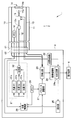
- FIG. 1 is a diagram illustrating a configuration of a main part of an endoscope system according to the first embodiment.
- an endoscope system 1 includes a scanning endoscope 2 that is inserted into a body cavity of a subject, a main body device 3 that can connect the endoscope 2, and a main body device 3 and a display device 4 connected to 3.
- the endoscope 2 includes an insertion portion 11 formed with an elongated shape and flexibility that can be inserted into a body cavity of a subject.
- a connector portion 61 for detachably connecting the endoscope 2 to the connector receiving portion 62 of the main body device 3 is provided at the proximal end portion of the insertion portion 11.
- an electrical connector device for electrically connecting the endoscope 2 and the main body device 3 is provided inside the connector portion 61 and the connector receiving portion 62.
- an optical connector device for optically connecting the endoscope 2 and the main body device 3 is provided inside the connector portion 61 and the connector receiving portion 62.
- an illumination fiber 12 for guiding the light supplied from the main body device 3 to the condensing optical system 14 and return light from the subject (
- one or more light receiving fibers 13 for receiving and guiding the reflected light to the main body device 3 are respectively inserted.
- the incident end portion including the light incident surface of the illumination fiber 12 is disposed inside the connector portion 61. Further, the end portion including the light emission surface of the illumination fiber 12 is disposed in the vicinity of the light incident surface of the lens 14 a provided at the distal end portion of the insertion portion 11.
- a light amount detection unit 12A is provided in the middle of the illumination fiber 12 inside the insertion unit 11.
- the light quantity detection unit 12A includes, for example, an optical branching device and a photodiode.
- the light quantity detection unit 12 ⁇ / b> A is configured to detect the light quantity of light passing through the illumination fiber 12, generate a light quantity detection signal corresponding to the detected light quantity, and output the signal to the main body device 3.
- the light amount detection unit 12A is not limited to the one provided inside the insertion unit 11, and for example, when the fluctuation of the light amount due to the connection between the connector unit 61 and the connector receiving unit 62 is difficult to occur, the main body device 3 may be provided in the vicinity of the connector receiving portion 62 in the inside.
- the incident end portion including the light incident surface of the light receiving fiber 13 is fixedly disposed around the light emitting surface of the lens 14 b on the distal end surface of the insertion portion 11. Further, the emission end portion including the light emission surface of the light receiving fiber 13 is arranged inside the connector portion 61.
- the light emitted from the main body device 3 is provided in the connector portion 61. Is incident on the light incident surface. Further, according to the configuration as described above, when the endoscope 2 and the main body device 3 are connected, the light incident from the light incident surface of the light receiving fiber 13 is connected to the connector portion 61 and the connector receiving portion. The light is emitted to the main body device 3 through 62.
- the condensing optical system 14 includes a lens 14a on which light having passed through the light exit surface of the illumination fiber 12 is incident, and a lens 14b that emits light having passed through the lens 14a to the subject.
- the emission end of the illumination fiber 12 is shaken by driving based on a drive signal supplied from the scanning control unit 22 of the main body device 3.
- An actuator unit 15 configured to be moved is provided.
- the actuator unit 15 is driven based on a drive signal supplied from the scanning control unit 22 of the main body device 3 to swing the emission end of the illumination fiber 12 along the first direction.
- a first actuator provided with one or more possible piezoelectric elements and a drive signal supplied from the scanning control unit 22 of the main body device 3
- the emission end portion is moved in the first direction.
- a second actuator including one or more piezoelectric elements that can be swung in a second direction orthogonal to each other.
- the transmittance T 1 in the illumination fiber 12 provided in the endoscope 2, the light receiving efficiency Le set for each model of the endoscope 2, and the endoscope 2 are provided inside the insertion portion 11.
- a memory 16 in which optical characteristic information including the transmittance T2 in the light receiving fiber 13 is stored is provided inside the insertion portion 11.
- the optical characteristic information stored in the memory 16 is read out by the parameter adjustment unit 27 of the main body device 3 when the connector portion 61 of the endoscope 2 and the connector receiving portion 62 of the main body device 3 are connected.
- the transmittance T1 is set as a dimensionless value of 0 or more and 1 or less according to the length of the illumination fiber 12, for example.
- the transmittance T1 is set as a value corresponding to each wavelength band of light supplied from the main body device 3, that is, a value corresponding to each of R light, G light, and B light described later.
- the light reception efficiency Le is, for example, the value of the predetermined wavelength band by the light receiving fiber 13 when a predetermined object disposed at a standard observation distance different for each model of the endoscope 2 is irradiated with light of a predetermined wavelength band. It is calculated as a value of the ratio between the amount of received light of the reflected light and the amount of light emitted from the condensing optical system 14 in the predetermined wavelength band.
- the light receiving efficiency Le is set as a value corresponding to each wavelength band of light supplied from the main body device 3, that is, a value corresponding to each of R light, G light, and B light described later.
- the above-mentioned standard observation distance is defined as, for example, a distance such that the contrast value of an image obtained by scanning a subject is a predetermined value or more.
- the model of the endoscope 2 is defined as different depending on an application site in a living body such as a respiratory organ and a digestive organ.
- the transmittance T2 is set as a dimensionless value of 0 or more and 1 or less according to the length and the number of the light receiving fibers 13, for example.
- the transmittance T2 is set as a value corresponding to each wavelength band of light supplied from the main body device 3, that is, a value corresponding to each of R light, G light, and B light described later.
- the main device 3 includes a light source unit 21, a scanning control unit 22, a light detection unit 23, an image processing unit 24, a light control unit 25, a memory 26, a parameter adjustment unit 27, a light source control unit 28, It is comprised.
- the light source unit 21 includes a light source 31a, a light source 31b, a light source 31c, and a multiplexer 32.
- the light source 31a includes, for example, a laser light source and is configured to be switched to an on state or an off state in accordance with the control of the light source control unit 28. Further, the light source 31a is configured to generate light in the red wavelength band (hereinafter also referred to as R light) with an output value according to the control of the light source control unit 28 in the on state.
- R light red wavelength band
- the light source 31b includes, for example, a laser light source or the like, and is configured to be switched to an on state or an off state in accordance with control of the light source control unit 28. Further, the light source 31b is configured to generate light in the green wavelength band (hereinafter also referred to as G light) with an output value according to the control of the light source control unit 28 in the on state.
- G light green wavelength band
- the light source 31c includes, for example, a laser light source or the like, and is configured to be switched to an on state or an off state in accordance with the control of the light source control unit 28.
- the light source 31c is configured to generate light in a blue wavelength band (hereinafter also referred to as B light) with an output value according to the control of the light source control unit 28 in the on state.
- B light a blue wavelength band
- the multiplexer 32 provides the connector receiver 62 with white light obtained by combining the R light emitted from the light source 31a, the G light emitted from the light source 31b, and the B light emitted from the light source 31c. It is comprised so that it can radiate
- the scanning control unit 22 includes, for example, a signal generator.
- the scanning control unit 22 generates a drive signal for swinging the emission end of the illumination fiber 12 in a predetermined scan pattern such as a spiral shape or a Lissajous shape, and the generated drive signal is transmitted to the actuator unit 15 and It is configured to output to the image processing unit 24.
- the light detection unit 23 detects light incident through the connector receiving unit 62 to generate an electrical signal, amplifies the generated electrical signal, and outputs a digital signal indicating a luminance value corresponding to the amplified electrical signal. It is configured to generate and output to the image processing unit 24.
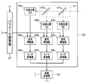
- the light detection unit 23 includes a spectroscopic optical system 41 including dichroic mirrors 41a and 41b, photodetectors 42a to 42c, signal amplifiers 43a to 43c, and A / D converters 44a to 44c.
- FIG. 2 is a diagram illustrating an example of the configuration of the light detection unit according to the first embodiment.
- the dichroic mirror 41a transmits R light and G light included in light incident through the connector receiving portion 62 to the dichroic mirror 41b side, and reflects B light included in the light to the photodetector 42c side. It has a good optical characteristic.
- the dichroic mirror 41b has optical characteristics such that R light incident through the dichroic mirror 41a is transmitted to the photodetector 42a side, and G light incident through the dichroic mirror 41a is reflected to the photodetector 42b side. It is comprised.
- the photodetector 42a is configured to include, for example, an avalanche photodiode or a photomultiplier tube.
- the photodetector 42a is configured to receive R light incident through the dichroic mirror 41b with a predetermined sensitivity, and generate and output an electrical signal corresponding to the amount of the received R light. .
- the photodetector 42b includes, for example, an avalanche photodiode or a photomultiplier tube.
- the light detector 42b is configured to receive the G light reflected by the dichroic mirror 41b with a predetermined sensitivity, and generate and output an electrical signal corresponding to the amount of the received G light.
- the photodetector 42c is configured to include, for example, an avalanche photodiode or a photomultiplier tube.
- the light detector 42c is configured to receive the B light reflected by the dichroic mirror 41a with a predetermined sensitivity, and generate and output an electrical signal corresponding to the amount of the received B light.
- the signal amplifier 43a is configured to amplify and output the electrical signal output from the photodetector 42a with the amplification factor adjusted by the parameter adjustment unit 27.
- the signal amplifier 43b is configured to amplify and output the electrical signal output from the photodetector 42b with the amplification factor adjusted by the parameter adjustment unit 27.
- the signal amplifier 43c is configured to amplify and output the electrical signal output from the photodetector 42c with the amplification factor adjusted by the parameter adjustment unit 27.
- the A / D converter 44a is configured to have a predetermined input voltage range.
- the A / D converter 44a converts the electrical signal output from the signal amplifier 43a into a gradation signal (hereinafter, also simply referred to as a digital signal) that has been gradationd so as to have a predetermined number of bits. Output.
- the A / D converter 44b is configured to have a predetermined input voltage range.
- the A / D converter 44b is configured to convert the electrical signal output from the signal amplifier 43b into a digital signal and output the digital signal.
- the A / D converter 44c is configured to have a predetermined input voltage range.
- the A / D converter 44c is configured to convert the electrical signal output from the signal amplifier 43c into a digital signal and output the digital signal.
- the image processing unit 24 includes, for example, an image processing circuit such as an AGC (auto gain control) circuit 24a. Further, the image processing unit 24 detects a scanning pattern of the subject based on the drive signal output from the scanning control unit 22, and detects the luminance value indicated by the digital signal output from the light detection unit 23. The image of the subject is generated by performing the interpolation process for interpolating the pixel information of each pixel that is not subject to mapping, and is mapped to the pixel at the position corresponding to. Further, the image processing unit 24 is configured to output the subject image generated as described above to the light control unit 25. In addition, the image processing unit 24 generates a display image by performing processing such as gain adjustment by the AGC circuit 24a on the subject image generated as described above, and the generated display image is displayed on the display device 4. It is configured to output to.
- AGC auto gain control
- the light control unit 25 includes, for example, a light control circuit.
- the light control unit 25 calculates the average value of the luminance values of the image output from the image processing unit 24, and sets the difference between the calculated average value of the luminance values and the predetermined brightness target value to zero.
- a dimming signal for approaching is generated, and the generated dimming signal is output to the light source control unit 28.
- the memory 26 includes an output upper limit value Pmax and an output lower limit value Pmin in the light sources 31a to 31c, a maximum gain value Mmax and a minimum gain value Mmin in the AGC circuit 24a, a transmittance C in the multiplexer 32, a connector unit 61, and The transmittance U in the connector receiving portion 62, the sensitivity Q in the photodetectors 42a to 42c, and the increase in the gradation value per volt with respect to the input voltage range (full scale) of the A / D converters 44a to 44c are shown.
- the increased gradation number A and the median value So of the gradation numbers represented by the digital signals generated by the A / D converters 44a to 44c are stored.
- the output upper limit value Pmax is, for example, a fixed value expressed in milliwatts, and is set based on a standard value of AEL (Accessible Emission Limit) defined in IEC 60825, which is an international standard that defines safety standards for laser products. ing. Further, the output upper limit value Pmax is set as a value corresponding to each of the light sources 31a to 31c.
- AEL Accessible Emission Limit
- the output lower limit value Pmin is, for example, a fixed value expressed in milliwatts, and is set as a value capable of maintaining laser emission from the light sources 31a to 31c. Further, the output lower limit value Pmin is set as a value corresponding to each of the light sources 31a to 31c.
- the maximum gain value Mmax and the minimum gain value Mmin are set as dimensionless fixed values used in gain adjustment by the AGC circuit 24a.
- the transmittance C and the transmittance U are set as dimensionless fixed values each having a value of 0 or more and 1 or less, for example. Further, the transmittance C and the transmittance U are set as values corresponding to the R light, the G light, and the B light, respectively.
- the sensitivity Q is, for example, a value represented by the number of volts per milliwatt (V / mW), and is set as a fixed value corresponding to each of the photodetectors 42a to 42c.
- the increased gradation number A is set as a fixed value corresponding to each of the A / D converters 44a to 44c, for example.
- the A / D converter 44b has an input voltage range of 0 to 10 volts, and a digital signal represented by 4096 gradations (12 bits) of 0 to 4095 is A / D converted.
- the increased gradation number A in the A / D converter 44b is set as 409.6.
- the median value So is set as a common fixed value in the A / D converters 44a to 44c. Specifically, for example, when a digital signal represented by 4096 gradations (12 bits) from 0 to 4095 is output from the A / D converters 44a to 44c, the median value So is set as 2047. Is done.
- the parameter adjustment unit 27 includes, for example, a CPU.
- the parameter adjustment unit 27 is configured to read the optical characteristic information stored in the memory 16 when the connector unit 61 and the connector receiving unit 62 are connected. Further, the parameter adjustment unit 27 calculates the amplification factor G corresponding to each of the signal amplifiers 43a to 43c based on each value included in the optical characteristic information read from the memory 16 and each value stored in the memory 26. Each is configured to adjust. The details of the method of adjusting the amplification factor G corresponding to each of the signal amplifiers 43a to 43c will be described later.
- the light source control unit 28 includes, for example, a CPU or a control circuit.
- the light source control unit 28 is configured to perform control for individually switching the light sources 31a to 31c to an on state or an off state.
- the light source control unit 28 is configured to set a minimum drive current value Imin corresponding to each of the light sources 31a to 31c based on the output lower limit value Pmin stored in the memory 26. Further, the light source control unit 28 is configured to set a maximum drive current value Imax corresponding to each of the light sources 31a to 31c based on the output upper limit value Pmax stored in the memory 26. Further, the light source control unit 28 determines the current value of the drive current supplied to the light sources 31a to 31c based on the light amount detection signal output from the light amount detection unit 12A and the dimming signal output from the dimming unit 25. The light amounts of R light, G light, and B light can be changed by changing within the range from the minimum driving current value Imin to the maximum driving current value Imax set as described above. ing.
- the optical path of light emitted from the multiplexer 32 to the connector receiver 62 the optical path of light emitted from the connector receiver 62 to the light detector 23, the condensing optical system 14, The description will be made assuming that the light loss at each part of the spectroscopic optical system 41 is 0 or minimal.
- a common adjustment method is used as an adjustment method for adjusting the gain Gr of the signal amplifier 43a, the gain Gg of the signal amplifier 43b, and the gain Gb of the signal amplifier 43c. can do. Therefore, hereinafter, a description will be given with a case where the gain Gg of the signal amplifier 43b is adjusted as a representative example.
- optical characteristic information including the transmittance T1g of G light in the illumination fiber 12, the light receiving efficiency Leg of G light, and the transmittance T2g of G light in the light receiving fiber 13 is stored in the memory 16. The description will be made assuming that
- the G light sensitivity Qg in the photodetector 42b and the increased gradation number Ag indicating the increase in gradation value per volt with respect to the input voltage range of the A / D converter 44b are stored in the memory 26. I will explain as a thing.
- the brightness value Sg after gain adjustment is obtained by performing gain adjustment by the AGC circuit 24a on the brightness value indicated by the digital signal output from the light detection unit 23 in response to reception of the G light. I try to get it in real time. Therefore, for example, when the current output value of the light source 31b is Pg and the current gain value of the AGC circuit 24a is M, the luminance value Sg after gain adjustment can be expressed as the following formula (1). it can.
- the luminance value of the display image displayed on the display device 4 is obtained by subjecting the value after the decimal point of the luminance value Sg after gain adjustment to a rounding process such as rounding off. Shall be.
- the parameter adjustment unit 27 is based on each value read from the memory 16 of the endoscope 2 connected to the main body device 3 and each value stored in the memory 26.
- the gain Gg of the signal amplifier 43b is adjusted so as to satisfy the condition expressed by the following mathematical formula (2).
- the output value Pg is adjusted to be the median value Pc within the variable range of the output value Pg.
- the gain value M is adjusted to be the median value Mc within the variable range of the gain value M, and the subject is observed at the standard observation distance corresponding to the endoscope 2, this corresponds to the median value So.
- the luminance value Sg can be acquired.
- the transmittance T1g, the light receiving efficiency Leg, and the transmittance T2g Regardless of the magnitude of each value, the output value Pg and the gain value M can be adjusted so that a suitable luminance value Sg can be obtained. Therefore, according to the present embodiment, even when a plurality of endoscopes having different amounts of light loss are used by being replaced, it is possible to perform a suitable brightness adjustment for each endoscope. .
- the multiplication value of the output lower limit value Pgmin and the minimum gain value Mmin in the above equation (2) is calculated. Since it can be set to 0, the amplification factor Gg of the signal amplifier 43b may be adjusted so as to satisfy the condition represented by the following formula (3).
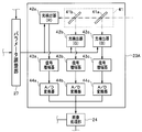
- FIG. 3 is a diagram illustrating an example different from FIG. 2 of the configuration of the light detection unit according to the first embodiment.
- the gain G and the increased number of gradations A are set as fixed values, while the sensitivity Q is adjusted by the parameter adjustment unit 27.
- the endoscope system 1 When the endoscope system 1 is configured by providing the light detection unit 23A, the output upper limit value Pmax and the output lower limit value Pmin, the maximum gain value Mmax and the minimum gain value Mmin, the transmittance C, and the transmittance U, amplification factor G, increased number of gradations A, and median value So are stored in the memory 26.
- the parameter adjustment unit 27 reads each value read from the memory 16 of the endoscope 2 connected to the main body device 3, and the memory 26, the sensitivity Qg of the photodetector 42b is adjusted so as to satisfy the condition expressed by the above equation (2) based on each value stored in the value 26, and further, the same method as the sensitivity Qg adjustment method is used.
- the sensitivity Qr of the photodetector 42a and the sensitivity Qb of the photodetector 42c may be adjusted.
- the sensitivities Qr, Qg, and Qb are defined as values obtained by multiplying, for example, the quantum efficiency, multiplication factor, and current-voltage conversion efficiency corresponding to each photodetector. Therefore, the parameter adjustment unit 27 can adjust the sensitivities Qr, Qg, and Qb, respectively, by adjusting the multiplication factors of the photodetectors 42a to 42c, for example. According to such an adjustment method, for example, the sensitivity Qg can be increased by increasing the multiplication factor of the photodetector 42b, and the sensitivity Qg can be reduced by decreasing the multiplication factor of the photodetector 42b. Can be reduced.
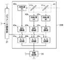
- FIG. 4 is a diagram illustrating an example different from FIGS. 2 and 3 of the configuration of the light detection unit according to the first embodiment.
- the sensitivity Q and the amplification factor G are set as fixed values, respectively, while the increased gradation number A is adjusted by the parameter adjustment unit 27.
- the endoscope system 1 When the endoscope system 1 is configured by providing the light detection unit 23B, the output upper limit value Pmax and the output lower limit value Pmin, the maximum gain value Mmax and the minimum gain value Mmin, the transmittance C, and the transmittance U, sensitivity Q, amplification factor G, and median So are stored in the memory 26.
- the parameter adjustment unit 27 reads each value read from the memory 16 of the endoscope 2 connected to the main body device 3, and the memory 26, the increased number of gradations Ag of the A / D converter 44b is adjusted so as to satisfy the condition expressed by the above formula (2) based on the values stored in FIG.
- the increase gradation number Ar of the A / D converter 44a and the increase gradation number Ab of the A / D converter 44c may be adjusted using the same method as the adjustment method.
- the parameter adjustment unit 27 can adjust the increased gradation numbers Ar, Ag, and Ab by adjusting the input voltage ranges of the A / D converters 44a to 44c, for example.
- the number of increased gradations Ag can be increased by narrowing the input voltage range of the A / D converter 44b, and the input voltage range of the A / D converter 44b. By increasing the range, the increased number of gradations Ag can be reduced.
- the light of the output upper limit value Pmax is emitted to a predetermined subject arranged at the standard observation distance of the endoscope 2. Irradiate, receive reflected light from the predetermined subject, and generate an average luminance value Sa of the image before gain adjustment generated according to the received reflected light, and a signal amplifier when the luminance value Sa is obtained
- the amplification factors Gt of 43a to 43c are individually associated and stored in the memory 26, and the amplification factors of the signal amplifiers 43a to 43c when the average luminance value of the image after gain adjustment is Sa are adjusted to Gt.
- An adjustment method may be applied.
- white balance adjustment may be performed in conjunction with the acquisition of the above-described average luminance value Sa.
- FIG. 5 is a diagram illustrating a configuration of a main part of the endoscope system according to the second embodiment.
- the endoscope system 1A includes an endoscope 2, a main body device 3A to which the endoscope 2 can be connected, and a display device 4 connected to the main body device 3A. Configured.
- the main unit 3A includes a light source unit 21, a scanning control unit 22, a light detection unit 23C, an image processing unit 24, a light control unit 25, a memory 26, a parameter adjustment unit 27, a light source control unit 28, It is comprised.
- the light detection unit 23C detects light incident through the connector unit 61 and the connector receiving unit 62, generates a digital signal indicating a luminance value according to the amount of the detected light, and displays the generated digital signal as an image. It is configured to output to the processing unit 24. Specifically, for example, as shown in FIG. 6, the light detection unit 23C includes a light detector 42d, a signal amplifier 43dc, and an A / D converter 44d.
- FIG. 6 is a diagram illustrating an example of the configuration of the light detection unit according to the second embodiment.
- the photodetector 42d includes, for example, an avalanche photodiode or a photomultiplier tube.
- the photodetector 42d is configured to receive light incident through the connector receiver 62, and generate and output an electrical signal corresponding to the amount of the received light.
- the signal amplifier 43d is configured to amplify and output the electrical signal output from the photodetector 42d with the amplification factor adjusted by the parameter adjustment unit 27.
- the A / D converter 44d is configured to convert the electrical signal output from the signal amplifier 43d into a digital signal and output the digital signal.
- the light source control unit 28 of the present embodiment is configured to perform an operation for emitting pulsed R light, G light, and B light while switching in this order every predetermined time ⁇ .
- the light source control unit 28 of the present embodiment generates a synchronization signal having a waveform that can individually identify the emission timing of the R light, the emission timing of the G light, and the emission timing of the B light. It is configured to output to the parameter adjustment unit 27.
- the parameter adjustment unit 27 of this embodiment is based on each value included in the optical characteristic information read from the memory 16, each value stored in the memory 26, and the synchronization signal output from the light source control unit 28. , The amplification factor of the signal amplifier 43d at the R light emission timing is adjusted to Gr1, the amplification factor of the signal amplifier 43d at the G light emission timing is adjusted to Gg1, and the amplification factor of the signal amplifier 43d at the B light emission timing is adjusted. It is configured to adjust to Gb1.
Landscapes
- Health & Medical Sciences (AREA)
- Life Sciences & Earth Sciences (AREA)
- Surgery (AREA)
- Physics & Mathematics (AREA)
- Optics & Photonics (AREA)
- Engineering & Computer Science (AREA)
- Biophysics (AREA)
- Animal Behavior & Ethology (AREA)
- Pathology (AREA)
- Radiology & Medical Imaging (AREA)
- Veterinary Medicine (AREA)
- Biomedical Technology (AREA)
- Heart & Thoracic Surgery (AREA)
- Medical Informatics (AREA)
- Molecular Biology (AREA)
- Nuclear Medicine, Radiotherapy & Molecular Imaging (AREA)
- General Health & Medical Sciences (AREA)
- Public Health (AREA)
- Signal Processing (AREA)
- Astronomy & Astrophysics (AREA)
- General Physics & Mathematics (AREA)
- Endoscopes (AREA)
- Instruments For Viewing The Inside Of Hollow Bodies (AREA)
Abstract
Description
図1から図4は、本発明の第1の実施例に係るものである。図1は、第1の実施例に係る内視鏡システムの要部の構成を示す図である。 (First embodiment)
1 to 4 relate to a first embodiment of the present invention. FIG. 1 is a diagram illustrating a configuration of a main part of an endoscope system according to the first embodiment.
Sg=Pg・Cg・Ug・T1g・Leg・T2g・Qg・Gg・Ag・M …(1)
すなわち、上記数式(1)によれば、出力値Pg及びゲイン値Mの組み合わせを変化させることにより、輝度値Sgを観察に適した大きさに調整するような明るさ調整を行うことができる。また、上記数式(1)によれば、例えば、出力値Pg及びゲイン値Mがそれぞれ一定の値であったとしても、透過率T1g、受光効率Leg及び透過率T2gの各値の大きさに応じた異なる輝度値Sgが取得される。
Sg = Pg · Cg · Ug · T1g · Leg · T2g · Qg · Gg · Ag · M (1)
That is, according to the above equation (1), by changing the combination of the output value Pg and the gain value M, it is possible to perform brightness adjustment that adjusts the luminance value Sg to a size suitable for observation. Further, according to the above formula (1), for example, even if the output value Pg and the gain value M are constant values, the values according to the values of the transmittance T1g, the light receiving efficiency Leg, and the transmittance T2g. Different brightness values Sg are acquired.
{(Pgmax・Mmax+Pgmin・Mmin)・Cg・Ug・T1g・Leg・T2g・Qg・Gg・Ag}/2=So …(2)
すなわち、上記数式(2)の条件を満たすように信号増幅器43bの増幅率Ggを調整することにより、例えば、出力値Pgの可変範囲内の中央値Pcとなるように出力値Pgが調整され、ゲイン値Mの可変範囲内の中央値Mcとなるようにゲイン値Mが調整され、さらに、内視鏡2に応じた標準観察距離で被写体が観察されている場合に、中央値Soに相当する輝度値Sgを取得することができる。
{(Pgmax · Mmax + Pgmin · Mmin) · Cg · Ug · T1g · Leg · T2g · Qg · Gg · Ag} / 2 = So (2)
That is, by adjusting the amplification factor Gg of the
{(Pgmax・Mmax・Cg・Ug・T1g・Leg・T2g・Qg・Gg・Ag}/2=So …(3)
一方、本実施例によれば、光検出部23の代わりに、例えば、図3に示すような、光検出部23と略同様の機能を具備する光検出部23Aを設けて内視鏡システム1を構成してもよい。図3は、第1の実施例に係る光検出部の構成の、図2とは異なる例を示す図である。
{(Pgmax · Mmax · Cg · Ug · T1g · Leg · T2g · Qg · Gg · Ag} / 2 = So (3)
On the other hand, according to the present embodiment, instead of the
図5及び図6は、本発明の第2の実施例に係るものである。図5は、第2の実施例に係る内視鏡システムの要部の構成を示す図である。 (Second embodiment)
5 and 6 relate to a second embodiment of the present invention. FIG. 5 is a diagram illustrating a configuration of a main part of the endoscope system according to the second embodiment.
Claims (6)
- 被写体に照射するための照明光を出射するように構成された光源部と、
前記照明光が照射された前記被写体からの戻り光を受光して導光するための受光用光学部材と、前記受光用光学部材の分光透過率、及び、前記被写体からの前記戻り光を前記受光用光学部材において受光する際の受光効率を含む光学特性情報が格納された記憶部と、
を有する内視鏡と、
前記受光用光学部材を経て入射される前記戻り光を受光して電気信号を生成し、当該生成した電気信号を増幅し、当該増幅した電気信号をデジタル信号に変換して出力するように構成された光検出部と、
前記光検出部から出力される前記デジタル信号に基づいて画像を生成し、当該生成した画像に対してゲイン調整を施すように構成された画像処理部と、
前記記憶部から読み込んだ前記光学特性情報と、前記光源部の出力値の可変範囲と、前記画像処理部のゲイン調整におけるゲイン値の可変範囲と、に基づき、前記受光用光学部材を経た前記戻り光が前記光検出部に入射されてから、前記デジタル信号が前記光検出部から出力されるまでのプロセスにおける所定のパラメータを調整するように構成されたパラメータ調整部と、
を有することを特徴とする内視鏡システム。 A light source unit configured to emit illumination light for irradiating a subject;
A light receiving optical member for receiving and guiding return light from the subject irradiated with the illumination light, a spectral transmittance of the light receiving optical member, and the light receiving from the subject. A storage unit storing optical characteristic information including light receiving efficiency when receiving light in the optical member for use;
An endoscope having
The return light incident through the light receiving optical member is received to generate an electrical signal, the generated electrical signal is amplified, the amplified electrical signal is converted into a digital signal and output. A light detector,
An image processing unit configured to generate an image based on the digital signal output from the light detection unit, and to perform gain adjustment on the generated image;
Based on the optical characteristic information read from the storage unit, the variable range of the output value of the light source unit, and the variable range of the gain value in the gain adjustment of the image processing unit, the return through the optical member for light reception A parameter adjusting unit configured to adjust a predetermined parameter in a process from when light is incident on the light detecting unit until the digital signal is output from the light detecting unit;
An endoscope system comprising: - 前記光源部は、前記照明光として、第1の光と、前記第1の光とは異なる波長帯域を具備する第2の光と、を個別に出射するように構成されており、
さらに、前記第1の光及び前記第2の光を所定時間毎に切り替えつつ前記光源部から出射させるための制御を行うように構成された光源制御部と、を有し、
前記パラメータ調整部は、前記所定のパラメータを、前記第1の光の出射タイミングと、前記第2の光の出射タイミングと、において個別に調整するように構成されている
ことを特徴とする請求項1に記載の内視鏡システム。 The light source unit is configured to individually emit the first light and the second light having a wavelength band different from the first light as the illumination light,
And a light source control unit configured to perform control for emitting the light from the light source unit while switching the first light and the second light at predetermined time intervals,
The parameter adjustment unit is configured to individually adjust the predetermined parameter at an emission timing of the first light and an emission timing of the second light. The endoscope system according to 1. - 前記所定のパラメータは、前記光検出部に入射された前記戻り光を受光するための光検出器における感度、前記電気信号を増幅するための信号増幅器における増幅率、または、前記電気信号を前記デジタル信号に変換するためのA/D変換器における入力電圧範囲のいずれかである
ことを特徴とする請求項1に記載の内視鏡システム。 The predetermined parameter is a sensitivity in a photodetector for receiving the return light incident on the photodetector, an amplification factor in a signal amplifier for amplifying the electrical signal, or the electrical signal in the digital The endoscope system according to claim 1, wherein the endoscope system is one of input voltage ranges in an A / D converter for converting into a signal. - 前記パラメータ調整部は、前記記憶部から読み込んだ前記光学特性情報と、前記出力値の可変範囲と、前記ゲイン値の可変範囲と、に基づき、前記出力値の可変範囲の中央値かつ前記ゲイン値の可変範囲の中央値において、前記画像処理部によるゲイン調整後の輝度値が所定の目標値となるように、前記感度、前記増幅率または前記入力電圧範囲のいずれかを調整する
ことを特徴とする請求項3に記載の内視鏡システム。 The parameter adjustment unit, based on the optical characteristic information read from the storage unit, the variable range of the output value, and the variable range of the gain value, the median value of the variable range of the output value and the gain value The sensitivity, the amplification factor, or the input voltage range is adjusted so that the luminance value after gain adjustment by the image processing unit becomes a predetermined target value at the median of the variable range of The endoscope system according to claim 3. - 前記所定の目標値は、前記デジタル信号により表される階調数の中央値に相当する輝度値である
ことを特徴とする請求項4に記載の内視鏡システム。 The endoscope system according to claim 4, wherein the predetermined target value is a luminance value corresponding to a median value of the number of gradation levels represented by the digital signal. - 前記内視鏡は、前記光源部から出射された前記照明光を導光して前記被写体に照射するための照明用光学部材をさらに有し、
前記照明用光学部材の分光透過率が前記光学特性情報に含まれている
ことを特徴とする請求項1に記載の内視鏡システム。 The endoscope further includes an illumination optical member for guiding the illumination light emitted from the light source unit and irradiating the subject.
The endoscope system according to claim 1, wherein a spectral transmittance of the illumination optical member is included in the optical characteristic information.
Priority Applications (4)
| Application Number | Priority Date | Filing Date | Title |
|---|---|---|---|
| EP15803937.0A EP3108802A4 (en) | 2014-06-02 | 2015-03-02 | Endoscope system |
| CN201580015163.XA CN106132279B (en) | 2014-06-02 | 2015-03-02 | Endoscopic system |
| JP2015558686A JP5963982B2 (en) | 2014-06-02 | 2015-03-02 | Image processing system and image processing apparatus |
| US15/269,015 US9877634B2 (en) | 2014-06-02 | 2016-09-19 | Image processing system and image processing apparatus |
Applications Claiming Priority (2)
| Application Number | Priority Date | Filing Date | Title |
|---|---|---|---|
| JP2014114357 | 2014-06-02 | ||
| JP2014-114357 | 2014-06-02 |
Related Child Applications (1)
| Application Number | Title | Priority Date | Filing Date |
|---|---|---|---|
| US15/269,015 Continuation US9877634B2 (en) | 2014-06-02 | 2016-09-19 | Image processing system and image processing apparatus |
Publications (1)
| Publication Number | Publication Date |
|---|---|
| WO2015186384A1 true WO2015186384A1 (en) | 2015-12-10 |
Family
ID=54766465
Family Applications (1)
| Application Number | Title | Priority Date | Filing Date |
|---|---|---|---|
| PCT/JP2015/056053 WO2015186384A1 (en) | 2014-06-02 | 2015-03-02 | Endoscope system |
Country Status (5)
| Country | Link |
|---|---|
| US (1) | US9877634B2 (en) |
| EP (1) | EP3108802A4 (en) |
| JP (1) | JP5963982B2 (en) |
| CN (1) | CN106132279B (en) |
| WO (1) | WO2015186384A1 (en) |
Cited By (1)
| Publication number | Priority date | Publication date | Assignee | Title |
|---|---|---|---|---|
| JP2017079930A (en) * | 2015-10-26 | 2017-05-18 | オリンパス株式会社 | Scan type endoscope apparatus |
Families Citing this family (6)
| Publication number | Priority date | Publication date | Assignee | Title |
|---|---|---|---|---|
| EP3114984A4 (en) * | 2014-08-19 | 2018-01-10 | Olympus Corporation | Light source device |
| JPWO2016116967A1 (en) * | 2015-01-23 | 2017-11-24 | オリンパス株式会社 | Endoscope lighting system |
| WO2018109799A1 (en) * | 2016-12-12 | 2018-06-21 | オリンパス株式会社 | Optical scanning endoscope |
| CN110785112B (en) * | 2017-06-28 | 2022-06-03 | 奥林巴斯株式会社 | Light source system, endoscope system, and light source control method |
| KR102500765B1 (en) * | 2017-11-22 | 2023-02-17 | 삼성전자주식회사 | Spectrometer, method for controlling output-gain of spectrometer, apparatus and method for measuring bio-information |
| CN108670172A (en) * | 2018-03-20 | 2018-10-19 | 广东欧谱曼迪科技有限公司 | Based on fluorescence navigation method of adjustment in the fluorescence navigation system and its art for surveying light feedback |
Citations (5)
| Publication number | Priority date | Publication date | Assignee | Title |
|---|---|---|---|---|
| JPS6148333A (en) * | 1984-08-13 | 1986-03-10 | オリンパス光学工業株式会社 | Endoscope photographing apparatus |
| JP2007143624A (en) * | 2005-11-24 | 2007-06-14 | Hamamatsu Photonics Kk | Fluorescence observation apparatus |
| WO2012132754A1 (en) * | 2011-03-31 | 2012-10-04 | オリンパスメディカルシステムズ株式会社 | Scanning endoscope |
| JP2013202167A (en) * | 2012-03-28 | 2013-10-07 | Fujifilm Corp | Image processing device and endoscope system |
| JP5363688B1 (en) * | 2012-01-11 | 2013-12-11 | オリンパスメディカルシステムズ株式会社 | Light irradiation apparatus, scanning endoscope apparatus, method for manufacturing light irradiation apparatus, and method for manufacturing scanning endoscope |
Family Cites Families (3)
| Publication number | Priority date | Publication date | Assignee | Title |
|---|---|---|---|---|
| JP4426519B2 (en) * | 2005-11-11 | 2010-03-03 | 株式会社日立ハイテクノロジーズ | Optical height detection method, electron beam measuring device, and electron beam inspection device |
| JP5143293B2 (en) * | 2010-06-24 | 2013-02-13 | オリンパスメディカルシステムズ株式会社 | Endoscope device |
| DE102013103333A1 (en) * | 2013-04-03 | 2014-10-09 | Karl Storz Gmbh & Co. Kg | Camera for recording optical properties and room structure properties |
-
2015
- 2015-03-02 CN CN201580015163.XA patent/CN106132279B/en not_active Expired - Fee Related
- 2015-03-02 WO PCT/JP2015/056053 patent/WO2015186384A1/en active Application Filing
- 2015-03-02 JP JP2015558686A patent/JP5963982B2/en active Active
- 2015-03-02 EP EP15803937.0A patent/EP3108802A4/en not_active Withdrawn
-
2016
- 2016-09-19 US US15/269,015 patent/US9877634B2/en active Active
Patent Citations (5)
| Publication number | Priority date | Publication date | Assignee | Title |
|---|---|---|---|---|
| JPS6148333A (en) * | 1984-08-13 | 1986-03-10 | オリンパス光学工業株式会社 | Endoscope photographing apparatus |
| JP2007143624A (en) * | 2005-11-24 | 2007-06-14 | Hamamatsu Photonics Kk | Fluorescence observation apparatus |
| WO2012132754A1 (en) * | 2011-03-31 | 2012-10-04 | オリンパスメディカルシステムズ株式会社 | Scanning endoscope |
| JP5363688B1 (en) * | 2012-01-11 | 2013-12-11 | オリンパスメディカルシステムズ株式会社 | Light irradiation apparatus, scanning endoscope apparatus, method for manufacturing light irradiation apparatus, and method for manufacturing scanning endoscope |
| JP2013202167A (en) * | 2012-03-28 | 2013-10-07 | Fujifilm Corp | Image processing device and endoscope system |
Non-Patent Citations (1)
| Title |
|---|
| See also references of EP3108802A4 * |
Cited By (1)
| Publication number | Priority date | Publication date | Assignee | Title |
|---|---|---|---|---|
| JP2017079930A (en) * | 2015-10-26 | 2017-05-18 | オリンパス株式会社 | Scan type endoscope apparatus |
Also Published As
| Publication number | Publication date |
|---|---|
| JP5963982B2 (en) | 2016-08-03 |
| US20170007097A1 (en) | 2017-01-12 |
| EP3108802A1 (en) | 2016-12-28 |
| EP3108802A4 (en) | 2018-02-14 |
| US9877634B2 (en) | 2018-01-30 |
| CN106132279A (en) | 2016-11-16 |
| JPWO2015186384A1 (en) | 2017-04-20 |
| CN106132279B (en) | 2018-08-28 |
Similar Documents
| Publication | Publication Date | Title |
|---|---|---|
| JP5963982B2 (en) | Image processing system and image processing apparatus | |
| JP6138203B2 (en) | Endoscope device | |
| US8550990B2 (en) | Endoscope system | |
| US9636005B2 (en) | Endoscope system having light intensity adjustment with movable optical system | |
| US8994804B2 (en) | Scanning endoscope system | |
| JP2011200410A (en) | Endoscope system including calibration means, and calibration method thereof | |
| EP2859836B1 (en) | Endoscope device | |
| JP6100674B2 (en) | Endoscope light source device and endoscope system | |
| JP5560215B2 (en) | Endoscope device | |
| JPWO2016080130A1 (en) | Observation device | |
| JP2017196430A (en) | Calibration method and endoscope system | |
| JP5974206B2 (en) | Light source device | |
| JP5927359B2 (en) | Lighting device | |
| JP6484257B2 (en) | LIGHTING DEVICE, ENDOSCOPE SYSTEM, AND COLOR CORRECTION DEVICE | |
| JP6325707B2 (en) | Endoscope light source device and endoscope system | |
| JP2002102147A (en) | Fluorescent image acquisition device | |
| JP6429507B2 (en) | Optical scanning observation system | |
| US11583165B2 (en) | Medical signal processing device, cap member, and medical signal processing method | |
| JP2018033783A (en) | Endoscope processor | |
| JP6599728B2 (en) | Scanning endoscope device | |
| JP2017018421A (en) | Endoscope system | |
| JP2012115513A (en) | Endoscope unit | |
| WO2018235227A1 (en) | Optical scanning-type observation device and method for adjusting white balance in optical scanning-type observation device |
Legal Events
| Date | Code | Title | Description |
|---|---|---|---|
| ENP | Entry into the national phase |
Ref document number: 2015558686 Country of ref document: JP Kind code of ref document: A |
|
| 121 | Ep: the epo has been informed by wipo that ep was designated in this application |
Ref document number: 15803937 Country of ref document: EP Kind code of ref document: A1 |
|
| REEP | Request for entry into the european phase |
Ref document number: 2015803937 Country of ref document: EP |
|
| WWE | Wipo information: entry into national phase |
Ref document number: 2015803937 Country of ref document: EP |
|
| NENP | Non-entry into the national phase |
Ref country code: DE |