WO2015186274A1 - 給水制御装置および給水装置 - Google Patents
給水制御装置および給水装置 Download PDFInfo
- Publication number
- WO2015186274A1 WO2015186274A1 PCT/JP2014/080823 JP2014080823W WO2015186274A1 WO 2015186274 A1 WO2015186274 A1 WO 2015186274A1 JP 2014080823 W JP2014080823 W JP 2014080823W WO 2015186274 A1 WO2015186274 A1 WO 2015186274A1
- Authority
- WO
- WIPO (PCT)
- Prior art keywords
- water supply
- valve
- steam generator
- bypass
- water
- Prior art date
- Legal status (The legal status is an assumption and is not a legal conclusion. Google has not performed a legal analysis and makes no representation as to the accuracy of the status listed.)
- Ceased
Links
Images



Classifications
-
- G—PHYSICS
- G21—NUCLEAR PHYSICS; NUCLEAR ENGINEERING
- G21D—NUCLEAR POWER PLANT
- G21D3/00—Control of nuclear power plant
- G21D3/08—Regulation of any parameters in the plant
-
- Y—GENERAL TAGGING OF NEW TECHNOLOGICAL DEVELOPMENTS; GENERAL TAGGING OF CROSS-SECTIONAL TECHNOLOGIES SPANNING OVER SEVERAL SECTIONS OF THE IPC; TECHNICAL SUBJECTS COVERED BY FORMER USPC CROSS-REFERENCE ART COLLECTIONS [XRACs] AND DIGESTS
- Y02—TECHNOLOGIES OR APPLICATIONS FOR MITIGATION OR ADAPTATION AGAINST CLIMATE CHANGE
- Y02E—REDUCTION OF GREENHOUSE GAS [GHG] EMISSIONS, RELATED TO ENERGY GENERATION, TRANSMISSION OR DISTRIBUTION
- Y02E30/00—Energy generation of nuclear origin
Definitions
- the present invention relates to a water supply control device and a water supply device for supplying a coolant to a steam generator provided in a nuclear facility.
- a water supply device described in Patent Document 1 is provided in a water supply pipe connected to a steam generator and a water supply pipe in order to supply a coolant to a steam generator provided in a nuclear facility.
- a water supply valve with a large rated capacity, a bypass pipe connected to the water supply pipe on the upstream side and the downstream side of the water supply valve, a bypass valve provided in the bypass pipe and having a smaller rated capacity than the water supply valve, and steam generation Based on the water level detection means provided so that the water level of the coolant in the vessel can be detected, and the water level deviation between the detected water level detected by the water level detection means and the preset target water level of the coolant in the steam generator
- a water supply control device provided to control the water supply valve and the bypass valve so as to control the water supply flow rate of the coolant supplied to the steam generator.
- This invention solves the subject mentioned above, and aims at providing the water supply control apparatus and water supply apparatus which can improve the responsiveness of control.
- the water supply control device provides the secondary coolant by heat exchange between the secondary coolant in the steam generator and the primary coolant output from the reactor cooling system.
- a water supply pipe connected to the steam generator so as to supply the secondary coolant to the steam generator, and a water supply valve provided in the water supply pipe in a nuclear facility that generates steam from
- a water supply control device for controlling a water supply device comprising: a valve opening degree of the water supply valve based on an output state of a nuclear reactor.
- the water supply valve is controlled with the valve opening degree according to the output state of the reactor as a target, the water level of the coolant in the steam generator is quickly set to the water level according to the output state of the reactor. You can get closer. As a result, the responsiveness of control can be improved.
- the valve opening of the water supply valve is set based on the output state of the reactor, the influence of the reverse response of the coolant level in the steam generator can be reduced, and the time required for adjustment can be shortened. .
- the water supply control device is the water supply control device according to the first invention, wherein the water level of the secondary coolant in the steam generator, the water supply flow rate of the secondary coolant in the water supply pipe, and the steam generation
- the valve opening degree of the water supply valve is adjusted based on the steam flow rate of the steam flowing out from the vessel.
- the water supply valve is controlled with the valve opening degree according to the output state of the reactor as a target, and in addition to this control, the water level of the coolant in the steam generator and the coolant level in the water supply pipe are controlled.
- the valve opening of the water supply valve based on the water supply flow rate and the steam flow rate of the steam flowing out of the steam generator, the water supply valve is adjusted to a more suitable valve opening according to the state in the steam generator. Can be controlled.
- the water supply control device is the water supply control device according to the first or second invention, wherein the water supply device includes a bypass pipe connected to the water supply pipe on an upstream side and a downstream side of the water supply valve, and the bypass A bypass valve that is provided in a pipe and has a smaller rated capacity than the water supply valve, and sets the valve opening of the bypass valve based on the output state of the reactor, and the steam generator The valve opening degree of the bypass valve is adjusted based on the water level of the secondary coolant in the inside.
- the water level of the coolant in the steam generator is controlled in the reactor in order to control the bypass valve with the valve opening degree according to the output state of the reactor as a target. It is possible to quickly approach the water level according to the output state. As a result, the responsiveness of control can be improved.
- the valve opening of the bypass valve is set based on the output state of the reactor, the influence of the response delay of the steam generator water level at the time of low output can be reduced, and the time required for adjustment can be shortened.
- bypass valve By controlling the bypass valve with the valve opening according to the output state of the reactor as a target, and adjusting the valve opening of the bypass valve based on the coolant level in the steam generator in addition to this control Even if the Cv value characteristic of the bypass valve differs from the design due to manufacturing errors, the bypass valve can be controlled to a more suitable valve opening according to the state of the steam generator.
- the water supply control device is the water supply control device according to the first or second aspect, wherein the water supply device includes a bypass pipe connected to the water supply pipe on the upstream side and the downstream side of the water supply valve, and the bypass A bypass valve that is provided in a pipe and has a smaller rated capacity than the water supply valve, and sets the valve opening of the bypass valve based on the output state of the reactor, and the steam generator The valve opening degree of the bypass valve is adjusted based on the water level of the secondary coolant in the inside and the feed water flow rate obtained corresponding to the capacity of the bypass valve.
- the water level of the coolant in the steam generator is controlled in the reactor in order to control the bypass valve with the valve opening degree according to the output state of the reactor as a target. It is possible to quickly approach the water level according to the output state. As a result, the responsiveness of control can be improved.
- the valve opening of the bypass valve is set based on the output state of the reactor, the influence of the response delay of the steam generator water level at the time of low output can be reduced, and the time required for adjustment can be shortened.
- the bypass valve is controlled with the valve opening according to the output state of the reactor as a target, and in addition to this control, based on the coolant level in the steam generator and the coolant flow rate in the bypass pipe
- the valve opening degree of the bypass valve By adjusting the valve opening degree of the bypass valve, even if the Cv value characteristic of the bypass valve differs from the design due to manufacturing errors, etc., a more suitable valve according to the state of the steam generator
- the bypass valve can be controlled to the opening degree.
- a water supply apparatus provides the water supply device of the steam generator by heat exchange between the secondary coolant in the steam generator and the primary coolant output from the reactor cooling system.
- a water supply pipe connected to the steam generator so as to supply the secondary coolant toward the steam generator in a nuclear facility that generates steam from the secondary coolant, and provided in the water supply pipe
- a water supply control device according to any one of the first to fourth inventions for controlling the valve and the bypass valve.
- the water level of the coolant in the steam generator is controlled according to the output state of the reactor by controlling the water supply valve and the bypass valve with the valve opening degree corresponding to the output state of the reactor as a target.
- the water level can be approached quickly.
- the responsiveness of control can be improved.
- the valve opening of the water supply valve and bypass valve is set based on the reactor power state, the water level of the coolant in the steam generator is reversed, and the steam generator is cooled at low power.
- the influence of the response delay of the water level of the material can be reduced, and the time required for adjustment can be shortened.
- the responsiveness of control can be improved.
- FIG. 1 is a schematic configuration diagram of a nuclear facility provided with a water supply apparatus according to an embodiment of the present invention.
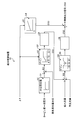
- FIG. 2 is a control block diagram relating to a water supply system in the water supply control device according to the embodiment of the present invention.
- FIG. 3 is a graph showing control related to the water supply system in the water supply control device according to the embodiment of the present invention.
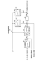
- FIG. 4 is a control block diagram relating to a water supply bypass system in the water supply control device according to the embodiment of the present invention.
- FIG. 5 is another control block diagram relating to a water supply bypass system in the water supply control device according to the embodiment of the present invention.
- FIG. 1 is a schematic configuration diagram of a nuclear facility equipped with a water supply apparatus according to the present embodiment.
- the nuclear facility 1 has a nuclear reactor 2.
- a reactor cooling system primary cooling system
- a turbine system secondary cooling system 200 that exchanges heat with the reactor cooling system 100. It consists of.
- a primary coolant flows, and in the turbine system 200, a secondary coolant flows.
- the reactor cooling system 100 has a steam generator 4 connected to the reactor 2 via a cold leg 3a and a hot leg 3b.
- the hot leg 3b is provided with a pressurizer 5, and the cold leg 3a is provided with a primary coolant pump 6.
- the reactor 2, the cold leg 3 a, the hot leg 3 b, the steam generator 4, the pressurizer 5, and the primary coolant pump 6 are accommodated in the reactor containment vessel 7.
- Reactor 2 is a pressurized water reactor as described above, and its interior is filled with a primary coolant.
- the primary coolant is light water in which boron used as a neutron moderator is dissolved.
- the nuclear reactor 2 contains a large number of fuel assemblies 8 therein, and a large number of control rods 9 for controlling the nuclear fission of the fuel assemblies 8 are removably provided in the fuel assemblies 8. ing.
- the high-temperature and high-pressure primary coolant flowing into the steam generator 4 is cooled by exchanging heat with the secondary coolant, and the cooled primary coolant is passed through the cold leg 3a by the primary coolant pump 6 to the nuclear reactor. Sent to 2. Then, the cooled primary coolant flows into the reactor 2, so that the reactor 2 is cooled. Thus, the primary coolant circulates between the nuclear reactor 2 and the steam generator 4.
- the turbine system 200 includes a turbine 12 connected to the steam generator 4 via the steam pipe 11, a condenser 13 connected to the turbine 12, and a water supply pipe 14 connecting the condenser 13 and the steam generator 4. A water supply pump 15 interposed between the two.
- the turbine 12 is connected to a generator 16.
- a series of operations in the turbine system 200 of the nuclear facility 1 will be described.
- the turbine 12 rotates.
- the generator 16 connected to the turbine 12 generates power.
- the steam flowing out of the turbine 12 flows into the condenser 13.
- the condenser 13 has a cooling pipe 17 disposed therein, and one of the cooling pipes 17 is connected to a water intake pipe 18 for supplying cooling water (for example, seawater).
- a drain pipe 19 for draining the cooling water is connected to.
- the condenser 13 cools the steam flowing in from the turbine 12 by the cooling pipe 17, thereby returning the steam to a liquid.
- the secondary coolant that has become liquid is sent to the steam generator 4 via the water supply pipe 14 by the water supply pump 15.
- the secondary coolant sent to the steam generator 4 becomes steam again by exchanging heat with the primary coolant in the steam generator 4.
- the secondary coolant is supplied toward the steam generator 4 while the flow rate is controlled by the water supply device 40 including the water supply pipe 14 and the water supply pump 15.
- the water supply device 40 is connected to the water supply pipe 14 by bypassing the water supply pipe 14, the water supply pump 15, the water supply valve 42 provided in the water supply pipe 14, and the water supply valve 42.
- a temperature sensor 49 and a second temperature sensor 50 provided in the hot leg 3b are provided.
- the water supply device 40 is controlled by a water supply control device 51.
- the water supply valve 42 is provided on the downstream side of the water supply pump 15 in the water supply pipe 14.
- the water supply valve 42 is a pneumatic control valve and has a larger rated capacity than the bypass valve 44.
- One end of the bypass pipe 43 is connected to the water supply pipe 14 on the upstream side of the water supply valve 42, and the other end is connected to the water supply pipe 14 on the downstream side of the water supply valve 42.
- the bypass valve 44 is provided in the bypass pipe 43.
- the bypass valve 44 is a pneumatic control valve similar to the water supply valve 42, but has a smaller rated capacity than the water supply valve 42.
- the water level gauge 45 is provided in the steam generator 4 and measures the water level of the secondary coolant in the steam generator 4.
- the water supply flow meter 46 is provided in the water supply pipe 14 on the downstream side of the water supply valve 42, and measures the flow rate of the liquid phase secondary coolant flowing in the water supply pipe 14. This water supply flow meter 46 corresponds to the capacity of the water supply valve 42 and measures the water supply flow rate in the secondary coolant flowing through the water supply valve 42.
- the steam flow meter 47 measures the steam flow rate in the steam (gas phase secondary coolant) flowing in the steam pipe 11.
- the feed water bypass flow meter 48 is provided in the bypass pipe 43 or the feed water pipe 14 on the downstream side of the bypass valve 44 and measures the flow rate of the liquid phase secondary coolant flowing in the feed water pipe 14.
- This water supply bypass flow meter 48 corresponds to the capacity of the bypass valve 44 and measures the narrow area water supply flow rate in the secondary coolant flowing through the bypass valve 44.
- the first temperature sensor 49 detects the temperature of the primary coolant flowing through the cold leg 3a.
- the second temperature sensor 50 detects the temperature of the primary coolant flowing through the hot leg 3b.
- the water supply control device 51 controls the water supply device 40 in an integrated manner.
- the water supply control device 51 is connected to a water level meter 45, a water supply flow meter 46, a steam flow meter 47, a water supply bypass flow meter 48, a first temperature sensor 49, and a second temperature sensor 50, and further includes a water supply valve 42 and a bypass valve. 44.
- the water supply control device 51 includes a water supply valve 42 and a bypass based on inputs from a water level meter 45, a water supply flow meter 46, a steam flow meter 47, a water supply bypass flow meter 48, a first temperature sensor 49, and a second temperature sensor 50. By controlling the valve 44, the water supply to the steam generator 4 is controlled.
- FIG. 2 is a control block diagram relating to the water supply system in the water supply control device according to the present embodiment.
- FIG. 3 is a graph which shows the control regarding the water supply system in the water supply control apparatus which concerns on this embodiment.
- 4 and 5 are control block diagrams relating to a water supply bypass system in the water supply control device according to the present embodiment.
- the water supply system means water supply control in which the water supply control device 51 controls the water supply valve 42 in the open state and does not control the bypass valve 44 in the closed state.
- the water supply bypass system means water supply control in which the water supply control device 51 controls the bypass valve 44 in an open state and does not control the water supply valve 42 in a closed state.
- the water supply control device 51 includes a first water level setting unit 52, a first variable gain setting unit 53, a first PI control unit (first feedback control unit) 54, A two-variable gain setting unit 55, a second PI control unit (second feedback control unit) 56, and a first valve opening signal output unit 57 are provided.
- the first water level setting unit 52 sets the target water level in the steam generator 4 according to the steam pressure around the first stage stationary blade that is around the inlet of the turbine 12 [turbine first stage pressure].
- the water level set value is set based on the graph G1 shown in FIG.
- the graph G1 is predetermined, the horizontal axis is the turbine first stage pressure, and the vertical axis is the water level set value. For this reason, when the turbine first stage pressure signal is input, the water supply control device 51 derives the water level set value based on the turbine first stage pressure and the graph G1 of the first water level setting unit 52.
- the first variable gain setting unit 53 sets a variable first proportional gain.
- the magnitude of the first proportional gain is set based on the temperature difference ⁇ T between the temperature of the cold leg 3 a obtained by the first temperature sensor 49 and the temperature of the hot leg 3 b obtained by the second temperature sensor 50.
- This temperature difference ⁇ T is derived by the feed water control device 51 based on inputs from the first temperature sensor 49 and the second temperature sensor 50 and is an index of the output of the nuclear reactor 2.
- the water supply control device 51 derives the first proportional gain from the graph G2 shown in FIG. 2 based on the derived temperature difference ⁇ T.
- the horizontal axis represents the temperature difference ⁇ T
- the vertical axis represents the first proportional gain.
- the first proportional gain is a preset lower limit proportional gain when the temperature difference ⁇ T is from 0 to T1, and from T1 to T2, the lower limit proportional gain is set to the preset upper limit proportional gain. Up to T2 and above is the upper limit proportional gain.
- the first PI control unit 54 is connected to the output side of the first variable gain setting unit 53.
- the first PI control unit 54 performs feedback control (PI control) on the control input signal by performing proportional control using the first proportional gain and integral control on the control input signal IS1 that is the water level deviation. Then, the first PI control unit 54 outputs the control input signal after the PI control as a control output signal (first control output signal) OS1.
- PI control feedback control
- the second variable gain setting unit 55 has a first PI control unit 54, a feed water flow meter 46, and a steam flow meter 47 connected to its input side, and a second PI control unit 56 connected to its output side. Then, the second variable gain setting unit 55 sets a variable second proportional gain.
- the magnitude of the second proportional gain is the control value of the derived signal derived from the control output signal OS1 output from the first PI controller 54 and the control input signal (second control input signal) IS2 that is a flow rate deviation.
- the control value of the derived signal is a deviation value in consideration of the water level deviation after PI control, which is the control output signal OS1 output from the first PI control unit 54, and the flow rate deviation, which is the control input signal IS2. .
- the water supply control device 51 derives the second proportional gain from the graph G3 shown in FIG. 2 based on the control value of the derived signal.
- the horizontal axis represents the control value of the derived signal
- the vertical axis represents the second proportional gain.
- the second proportional gain is a preset lower limit proportional gain when the control value is 0, that is, when the deviation is 0.
- the second proportional gain increases from a lower limit proportional gain to a preset upper limit proportional gain when the control value is from 0 to S1, and when the control value is larger than S1, the second proportional gain is an upper limit proportional gain.
- the second proportional gain increases from the lower limit proportional gain to a preset upper limit proportional gain when the control value is from 0 to -S1, and is the upper limit proportional gain when the control value is smaller than -S1.
- the second PI control unit 56 is connected to the output side of the second variable gain setting unit 55.
- the second PI control unit 56 performs feedback control (PI control) on the derived signal by performing proportional control using the second proportional gain and integral control on the derived signal. Then, the second PI control unit 56 outputs the derived signal after the PI control as a control output signal (second control output signal) OS2 for controlling the water supply valve 42.
- PI control feedback control
- the first valve opening signal output unit 57 is a control output signal (third control output signal) OS3 for controlling the valve opening of the water supply valve 42 based on the temperature difference ⁇ T that is an index of the output of the reactor 2.
- the water supply control device 51 derives the valve opening degree of the water supply valve 42 from the graph G4 shown in FIG. 2 based on the derived temperature difference ⁇ T.
- the horizontal axis represents the temperature difference ⁇ T
- the vertical axis represents the valve opening.
- the water supply control device 51 controls the water supply valve 42 by combining the control output signal OS3 output from the first valve opening signal output unit 57 and the control output signal OS2 output from the second PI control unit 56.
- An output signal (fourth control output signal) OS4 is output. That is, the water supply control device 51 outputs the control output signal OS3 of the valve opening of the water supply valve 42 based on the temperature difference ⁇ T that is the output state of the reactor 2 from the first valve opening signal output unit 57. As shown by a broken line in FIG. 3, the valve opening degree of the water supply valve 42, which is a target value, is set.
- the water supply control apparatus 51 outputs this control output signal OS3 to the water supply valve 42, and controls the valve opening degree of the water supply valve 42 to a target value as shown by a solid line in FIG.
- the feed water control device 51 is based on the water level of the secondary coolant in the steam generator 4, the feed water flow rate of the secondary coolant in the feed water pipe 14, and the steam flow rate of the steam flowing out of the steam generator 4.
- the valve opening degree of the water supply valve 42 is adjusted as shown by the solid line in FIG. That is, in consideration of the water level that can be changed by the output of the reactor 2 until the valve opening degree of the water supply valve 42 is controlled to the target value (range shown by hatching in FIG. 3), this is added and adjusted.
- 3 indicates the water supply control when the control output signal OS3 output from the first valve opening signal output unit 57 is not used.
- the water supply control device 51 includes a second water level setting unit 62, a third variable gain setting unit 63, and a second valve opening signal output unit 64, as shown in FIG. Yes.
- the second water level setting unit 62 sets the target water level in the steam generator 4 according to the steam pressure around the first stage stationary blade that is around the inlet of the turbine 12 [turbine first stage pressure].
- the water level set value is set based on the graph G5 shown in FIG.
- the graph G5 is predetermined, the horizontal axis is the turbine first stage pressure, and the vertical axis is the water level set value. For this reason, when the turbine first stage pressure signal is input, the water supply control device 51 derives the water level set value based on the turbine first stage pressure and the graph G5 of the water level setting unit 62.
- the third variable gain setting unit 63 sets a variable third proportional gain.
- the magnitude of the third proportional gain is set based on the temperature difference ⁇ T between the temperature of the cold leg 3 a obtained by the first temperature sensor 49 and the temperature of the hot leg 3 b obtained by the second temperature sensor 50.
- This temperature difference ⁇ T is derived by the feed water control device 51 based on inputs from the first temperature sensor 49 and the second temperature sensor 50 and is an index of the output of the nuclear reactor 2.
- the water supply control device 51 derives the third proportional gain from the graph G6 shown in FIG. 4 based on the derived temperature difference ⁇ T.
- the horizontal axis represents the temperature difference ⁇ T
- the vertical axis represents the third proportional gain.
- the third proportional gain is a preset upper limit proportional gain from a preset lower limit proportional gain KL until the temperature difference ⁇ T is 0 to 20% (corresponding to an output region in which the bypass valve 44 is used). It increases to KH, and 20% or more is the upper limit proportional gain KH.
- the second valve opening signal output unit 64 is a control output signal (fifth control output signal) OS5 for controlling the valve opening of the bypass valve 44 based on the temperature difference ⁇ T that is an index of the output of the reactor 2.
- the horizontal axis represents the temperature difference ⁇ T
- the vertical axis represents the valve opening.
- the water supply control device 51 uses the control output signal OS5 output from the second valve opening signal output unit 64 and the third proportional gain of the third variable gain setting unit 63 to control the bypass valve 44.
- a signal (sixth control output signal) OS6 is output. That is, the water supply control device 51 outputs a control output signal OS5 of the valve opening degree of the bypass valve 44 based on the temperature difference ⁇ T that is an index of the output of the nuclear reactor 2 from the second valve opening degree signal output unit 64. Then, the valve opening degree of the bypass valve 44 which is a target value is set. And the water supply control apparatus 51 outputs this control output signal OS5 to the bypass valve 44, for example, controls the valve opening degree of the bypass valve 44 to a target value, as shown by the continuous line in FIG.
- the water supply control device 51 adjusts the valve opening degree of the bypass valve 44 based on the water level of the secondary coolant in the steam generator 4, for example, as shown by a solid line in FIG. That is, in consideration of the water level that can be reduced by the output of the reactor 2 until the valve opening degree of the bypass valve 44 is controlled to the target value (for example, the range shown by hatching in FIG. 3), this is added and adjusted.
- . 3 corresponds to the water supply control in the case where the control output signal OS5 output from the second valve opening signal output unit 64 is not used.
- the water supply control device 51 in addition to the second water level setting unit 62, the third variable gain setting unit 63, and the second valve opening signal output unit 64, as shown in FIG.
- the third PI control unit (third feedback control unit) 65, the steam flow signal output unit 66, and the fourth PI control unit (third feedback control unit) 67 may be included.
- the second water level setting unit 62 sets the target water level in the steam generator 4 according to the steam pressure around the first stage stationary blade that is around the inlet of the turbine 12 [turbine first stage pressure].
- the water level set value is set based on the graph G5 shown in FIG.
- the graph G5 is predetermined, the horizontal axis is the turbine first stage pressure, and the vertical axis is the water level set value. For this reason, when the turbine first stage pressure signal is input, the water supply control device 51 derives the water level set value based on the turbine first stage pressure and the graph G5 of the second water level setting unit 62.
- the third variable gain setting unit 63 sets a variable third proportional gain.
- the magnitude of the third proportional gain is set based on the temperature difference ⁇ T between the temperature of the cold leg 3 a obtained by the first temperature sensor 49 and the temperature of the hot leg 3 b obtained by the second temperature sensor 50.
- This temperature difference ⁇ T is derived by the feed water control device 51 based on inputs from the first temperature sensor 49 and the second temperature sensor 50 and is an index of the output of the nuclear reactor 2.
- the water supply control device 51 derives a third proportional gain from the graph G6 shown in FIG. 5 based on the derived temperature difference ⁇ T.
- the horizontal axis represents the temperature difference ⁇ T
- the vertical axis represents the third proportional gain.
- the third proportional gain is a preset upper limit proportional gain from a preset lower limit proportional gain KL until the temperature difference ⁇ T is 0 to 20% (corresponding to an output region in which the bypass valve 44 is used). It increases to KH, and 20% or more is the upper limit proportional gain KH.
- the third PI control unit 65 is connected to the output side of the third variable gain setting unit 63.
- the third PI control unit 65 performs feedback control (PI control) on the derived signal by performing proportional control using the third proportional gain and integral control on the derived signal. Then, the third PI control unit 65 outputs the control input signal after PI control as a control output signal (seventh control output signal) OS7.
- PI control feedback control
- the steam flow signal output unit 66 outputs a control output signal (eighth control output signal) OS8 that is a flow rate of steam flowing out of the steam generator 4 based on the temperature difference ⁇ T that is an index of the output of the reactor 2. That is, the water supply control device 51 derives the steam flow rate of the steam generator 4 from the graph G8 shown in FIG. 5 based on the derived temperature difference ⁇ T.
- the horizontal axis represents the temperature difference ⁇ T
- the vertical axis represents the steam flow rate.
- the fourth PI controller 67 is connected to the output side of the third PI controller 65 and the steam flow signal output unit 66.
- the fourth PI controller 67 controls the third PI controller 65 with respect to the flow rate deviation between the narrow area water supply flow detected by the water supply bypass flow meter 48 and the steam flow output from the steam flow signal output unit 66.
- the control input signal is feedback-controlled (PI control).
- the fourth PI control unit 67 then outputs the control input signal after PI control as a control output signal (ninth control output signal) OS9 for controlling the bypass valve 44.
- the second valve opening signal output unit 64 is a control output signal (fifth control output signal) OS5 for controlling the valve opening of the bypass valve 44 based on the temperature difference ⁇ T that is an index of the output of the reactor 2.
- the horizontal axis represents the temperature difference ⁇ T
- the vertical axis represents the valve opening.
- the water supply control device 51 controls the bypass valve 44 by combining the control output signal OS5 output from the second valve opening signal output unit 64 and the control output signal OS9 output from the fourth PI control unit 67.
- An output signal (tenth control output signal) OS10 is output. That is, the water supply control device 51 outputs a control output signal OS5 of the valve opening degree of the bypass valve 44 based on the temperature difference ⁇ T that is an index of the output of the nuclear reactor 2 from the second valve opening degree signal output unit 64.
- the valve opening of the bypass valve 44 which is a target value, is set as shown by a broken line in FIG.
- the water supply control apparatus 51 outputs this control output signal OS5 to the bypass valve 44, for example, controls the valve opening degree of the bypass valve 44 to a target value, as shown by the continuous line in FIG. Further, the feed water control device 51 outputs the water level of the secondary coolant in the steam generator 4, the narrow area feed water flow rate of the secondary coolant in the bypass pipe 43 or the feed water pipe 14, and the steam flow signal output unit 66. By outputting a control output signal OS9 based on the steam flow rate, the valve opening degree of the bypass valve 44 is adjusted as shown by a solid line in FIG.
- . 3 corresponds to the water supply control in the case where the control output signal OS5 output from the second valve opening signal output unit 64 is not used.
- the water supply control device 51 of this embodiment is configured so that the secondary coolant of the steam generator 4 is exchanged by heat exchange between the secondary coolant of the steam generator 4 and the primary coolant output from the reactor cooling system 100.
- a water supply pipe 14 connected to the steam generator 4 so as to supply a secondary coolant to the steam generator 4 and water supply provided in the water supply pipe 14
- the valve opening of the water supply valve 42 is set based on the output state of the nuclear reactor 2.
- the output state of the reactor 2 index of the output of the reactor 2
- the temperature of the primary coolant output from the reactor cooling system 100 and the steam generator 4 Based on the temperature difference ⁇ T with the temperature of the primary coolant that is cooled by heat exchange with the secondary coolant (coolant) and sent to the reactor 2
- the valve opening according to the output state of the reactor 2 is By controlling the water supply valve 42 as a target, the water level of the secondary coolant in the steam generator 4 can be quickly brought close to the water level according to the output state of the reactor 2. As a result, the responsiveness of control can be improved.
- valve opening of the water supply valve 42 is set based on the output state of the nuclear reactor 2, the influence of the reverse response of the water level of the secondary coolant in the steam generator 4 can be reduced, and the adjustment can be made. The time required can be shortened.
- the water supply control device 51 of the present embodiment includes the water level of the secondary coolant in the steam generator 4, the feed water flow rate of the secondary coolant in the feed water pipe 14, and the steam flow rate of the steam flowing out from the steam generator 4. Based on the above, the valve opening degree of the water supply valve 42 is adjusted.
- the water supply valve 42 is controlled with the valve opening according to the output state of the reactor 2 as a target, and in addition to this control, the water level of the secondary coolant in the steam generator 4, By adjusting the valve opening degree of the feed water valve 42 based on the feed water flow rate of the secondary coolant in the feed water pipe 14 and the steam flow rate of the steam flowing out from the steam generator 4, the state in the steam generator 4 is obtained. Accordingly, the water supply valve 42 can be controlled to a more suitable valve opening.
- the water supply device 40 includes a bypass pipe 43 connected to the water supply pipe 14 on the upstream side and the downstream side of the water supply valve 42, and the water supply valve 42 provided on the bypass pipe 43. And a bypass valve 44 having a smaller rated capacity than that of the reactor.
- the valve opening degree of the bypass valve 44 is set based on the output state of the nuclear reactor 2, and the secondary coolant in the steam generator 4 is set.
- the valve opening degree of the bypass valve 44 is adjusted based on the water level.
- this water supply control device 51 even in the water supply from the bypass pipe 43 side, the output state of the reactor 2, specifically, the temperature of the primary coolant output from the reactor cooling system 100, the steam generator 4, based on the temperature difference ⁇ T with the temperature of the primary coolant that is cooled by heat exchange with the secondary coolant and sent to the reactor 2, the valve opening according to the output state of the reactor 2 is bypassed as a target
- the valve 44 By controlling the valve 44, the water level of the secondary coolant in the steam generator 4 can be quickly brought close to the water level according to the output state of the reactor 2. As a result, the responsiveness of control can be improved.
- the opening degree of the bypass valve 44 is set based on the output state of the nuclear reactor 2, it is possible to reduce the influence of the response delay at the time of low output of the water level of the secondary coolant in the steam generator 4. And the time required for adjustment can be shortened. Then, the bypass valve 44 is controlled with the valve opening according to the output state of the reactor 2 as a target, and in addition to this control, the bypass valve 44 is opened based on the water level of the secondary coolant in the steam generator 4. By adjusting the degree, even if the Cv value characteristics of the bypass valve 44 differ from the design due to manufacturing errors, etc., the valve opening degree is more suitable for the state of the steam generator 4. The valve 44 can be controlled.
- the water supply device 40 includes a bypass pipe 43 connected to the water supply pipe 14 on the upstream side and the downstream side of the water supply valve 42, and the water supply valve 42 provided on the bypass pipe 43. And a bypass valve 44 having a smaller rated capacity than that of the reactor.
- the valve opening degree of the bypass valve 44 is set based on the output state of the nuclear reactor 2, and the secondary coolant in the steam generator 4 is set.
- the valve opening degree of the bypass valve 44 is adjusted based on the water level and the feed water flow rate obtained corresponding to the capacity of the bypass valve 44.
- this water supply control device 51 even in the water supply from the bypass pipe 43 side, the output state of the reactor 2, specifically, the temperature of the primary coolant output from the reactor cooling system 100, the steam generator 4, based on the temperature difference ⁇ T with the temperature of the primary coolant that is cooled by heat exchange with the secondary coolant and sent to the reactor 2, the valve opening according to the output state of the reactor 2 is bypassed as a target
- the valve 44 By controlling the valve 44, the water level of the secondary coolant in the steam generator 4 can be quickly brought close to the water level according to the output state of the reactor 2. As a result, the responsiveness of control can be improved.
- the opening degree of the bypass valve 44 is set based on the output state of the nuclear reactor 2, it is possible to reduce the influence of the response delay at the time of low output of the water level of the secondary coolant in the steam generator 4. And the time required for adjustment can be shortened. Then, the bypass valve 44 is controlled with the valve opening according to the output state of the reactor 2 as a target. In addition to this control, the water level of the secondary coolant in the steam generator 4 and the secondary cooling in the bypass pipe 43 are controlled. By adjusting the valve opening degree of the bypass valve 44 based on the feed water flow rate of the material, even if the Cv value characteristic of the bypass valve 44 is different from the design due to manufacturing errors, steam is generated. The bypass valve 44 can be controlled to a more suitable valve opening according to the state of the vessel 4.
- the water supply device 40 of the present embodiment generates steam from the secondary coolant of the steam generator 4 by heat exchange between the secondary coolant of the steam generator 4 and the primary coolant output from the reactor cooling system 100.
- a water supply pipe 14 connected to the steam generator 4 so as to supply a secondary coolant to the steam generator 4, a water supply valve 42 provided in the water supply pipe 14, and a water supply A bypass pipe 43 connected to the water supply pipe 14 on the upstream side and the downstream side of the valve 42, a bypass valve 44 provided in the bypass pipe 43 and having a smaller rated capacity than the water supply valve 42, the water supply valve 42 and the bypass A water supply control device 51 for controlling the valve 44.
- the water level of the secondary coolant in the steam generator 4 is controlled by controlling the water supply valve 42 and the bypass valve 44 with the valve opening according to the output state of the reactor 2 as a target.
- the water level corresponding to the output state of the furnace 2 can be quickly approached.
- the responsiveness of control can be improved.
- the valve opening degree of the water supply valve 42 and the bypass valve 44 is set based on the output state of the nuclear reactor 2, the reverse response of the water level of the secondary coolant in the steam generator 4 and at the time of low output The influence of the response delay of the coolant level in the steam generator can be reduced, and the time required for adjustment can be shortened.
Landscapes
- Physics & Mathematics (AREA)
- Engineering & Computer Science (AREA)
- Plasma & Fusion (AREA)
- General Engineering & Computer Science (AREA)
- High Energy & Nuclear Physics (AREA)
- Monitoring And Testing Of Nuclear Reactors (AREA)
Abstract
制御の即応性を向上すること。すなわち、蒸気発生器(4)内の二次冷却材と原子炉冷却系(100)から出力される一次冷却材との熱交換により蒸気発生器(4)の二次冷却材から蒸気を発生させる原子力施設(1)にて、蒸気発生器(4)へ向けて二次冷却材を供給するように蒸気発生器(4)に接続された給水管(14)と、給水管(14)に設けられた給水弁(42)と、を備える給水装置(40)を制御するための給水制御装置(51)であって、原子炉(2)の出力状態に基づいて給水弁(42)の弁開度を設定する。
Description
本発明は、原子力施設に設けられた蒸気発生器へ向けて冷却材を供給するための給水制御装置および給水装置に関する。
従来、例えば、特許文献1に記載の給水装置は、原子力施設に設けられた蒸気発生器へ向けて冷却材を供給するため、蒸気発生器に接続された給水管と、給水管に設けられて定格容量の大きな給水弁と、給水弁の上流側と下流側とで給水管に接続されるバイパス管と、バイパス管に設けられて給水弁に比して定格容量の小さなバイパス弁と、蒸気発生器内の冷却材の水位を検出可能に設けられた水位検出手段と、水位検出手段によって検出された検出水位と予め設定された蒸気発生器内の冷却材の目標水位との水位偏差に基づいて給水弁とバイパス弁とを制御して蒸気発生器に供給される冷却材の給水流量を制御可能に設けられた給水制御装置と、を備えている。
従来の給水制御は、負荷遮断などの大幅負荷急減が生じた際、蒸気発生器から流出する蒸気流量が減少して蒸気発生器の冷却材の保有水量は増加傾向にあるにも関わらず、蒸気発生器の内圧上昇により蒸気発生器内の冷却材の水位が低下する水位の逆応答により、給水制御装置の積分要素が過大となる。この結果、蒸気発生器内の冷却材の水位が目標水位に回復した後においても、給水流量が蒸気流量よりも多い状態が継続し、目標水位を行き過ぎるオーバーシュート量が大きくなる。また、蒸気発生器内の冷却材の水位の調整において、積分要素により負荷変化後の蒸気流量に見合った弁開度に変化するが、蒸気流量と給水流量との不一致量が蓄積されていると、調整に時間を要することになる。また、原子炉の出力状態が低く、蒸気流量、給水流量が少ないプラント状態において、負荷変動が生じた場合は、その蒸気流量変動が蒸気発生器水位の変化となって現れてくるまでに時間がかかる傾向にあることから、蒸気発生器内の冷却材の水位の調整に時間を要することになる。
本発明は上述した課題を解決するものであり、制御の即応性を向上することのできる給水制御装置および給水装置を提供することを目的とする。
上述の目的を達成するために、第1の発明の給水制御装置は、蒸気発生器内の二次冷却材と原子炉冷却系から出力される一次冷却材との熱交換により前記二次冷却材から蒸気を発生させる原子力施設にて、前記蒸気発生器へ向けて前記二次冷却材を供給するように前記蒸気発生器に接続された給水管と、前記給水管に設けられた給水弁と、を備える給水装置を制御するための給水制御装置であって、原子炉の出力状態に基づいて前記給水弁の弁開度を設定することを特徴とする。
この給水制御装置によれば、原子炉の出力状態に応じた弁開度を目標として給水弁を制御するため、蒸気発生器内の冷却材の水位を原子炉の出力状態に応じた水位にいち早く近づけることができる。この結果、制御の即応性を向上することができる。しかも、原子炉の出力状態に基づいて給水弁の弁開度を設定することから、蒸気発生器内の冷却材の水位の逆応答の影響を小さくすることができ、調整に要する時間を短縮できる。
また、第2の発明の給水制御装置は、第1の発明において、前記蒸気発生器内の前記二次冷却材の水位と、前記給水管における前記二次冷却材の給水流量と、前記蒸気発生器から流出する蒸気の蒸気流量と、に基づいて前記給水弁の弁開度を調整することを特徴とする。
この給水制御装置によれば、原子炉の出力状態に応じた弁開度を目標として給水弁を制御し、この制御に加えて蒸気発生器内の冷却材の水位と、給水管における冷却材の給水流量と、蒸気発生器から流出する蒸気の蒸気流量と、に基づいて給水弁の弁開度を調整することで、蒸気発生器内の状態に応じてより適した弁開度に給水弁を制御することができる。
また、第3の発明の給水制御装置は、第1または第2の発明において、前記給水装置は、前記給水弁の上流側と下流側とで前記給水管に接続されるバイパス管と、前記バイパス管に設けられて前記給水弁に比して定格容量の小さいバイパス弁と、を備えており、前記原子炉の出力状態に基づいて前記バイパス弁の弁開度を設定するとともに、前記蒸気発生器内の前記二次冷却材の水位に基づいて前記バイパス弁の弁開度を調整することを特徴とする。
この給水制御装置によれば、バイパス管側からの給水においても、原子炉の出力状態に応じた弁開度を目標としてバイパス弁を制御するため、蒸気発生器内の冷却材の水位を原子炉の出力状態に応じた水位にいち早く近づけることができる。この結果、制御の即応性を向上することができる。しかも、原子炉の出力状態に基づいてバイパス弁の弁開度を設定することから、低出力時の蒸気発生器水位の応答遅れの影響を小さくすることができ、調整に要する時間を短縮できる。そして、原子炉の出力状態に応じた弁開度を目標としてバイパス弁を制御し、この制御に加えて蒸気発生器内の冷却材の水位に基づいてバイパス弁の弁開度を調整することで、仮に、製作誤差などによりバイパス弁のCv値特性が設計と差が生じた場合であっても、蒸気発生器の状態に応じてより適した弁開度にバイパス弁を制御することができる。
また、第4の発明の給水制御装置は、第1または第2の発明において、前記給水装置は、前記給水弁の上流側と下流側とで前記給水管に接続されるバイパス管と、前記バイパス管に設けられて前記給水弁に比して定格容量の小さいバイパス弁と、を備えており、前記原子炉の出力状態に基づいて前記バイパス弁の弁開度を設定するとともに、前記蒸気発生器内の前記二次冷却材の水位と、前記バイパス弁の容量に対応して得られる給水流量と、に基づいて前記バイパス弁の弁開度を調整することを特徴とする。
この給水制御装置によれば、バイパス管側からの給水においても、原子炉の出力状態に応じた弁開度を目標としてバイパス弁を制御するため、蒸気発生器内の冷却材の水位を原子炉の出力状態に応じた水位にいち早く近づけることができる。この結果、制御の即応性を向上することができる。しかも、原子炉の出力状態に基づいてバイパス弁の弁開度を設定することから、低出力時の蒸気発生器水位の応答遅れの影響を小さくすることができ、調整に要する時間を短縮できる。そして、原子炉の出力状態に応じた弁開度を目標としてバイパス弁を制御し、この制御に加えて蒸気発生器内の冷却材の水位と、バイパス管における冷却材の給水流量と、に基づいてバイパス弁の弁開度を調整することで、仮に、製作誤差などによりバイパス弁のCv値特性が設計と差が生じた場合であっても、蒸気発生器の状態に応じてより適した弁開度にバイパス弁を制御することができる。
上述の目的を達成するために、第5の発明の給水装置は、蒸気発生器内の二次冷却材と原子炉冷却系から出力される一次冷却材との熱交換により前記蒸気発生器の前記二次冷却材から蒸気を発生させる原子力施設にて、前記蒸気発生器へ向けて前記二次冷却材を供給するように前記蒸気発生器に接続された給水管と、前記給水管に設けられた給水弁と、前記給水弁の上流側と下流側とで前記給水管に接続されるバイパス管と、前記バイパス管に設けられて前記給水弁に比して定格容量の小さいバイパス弁と、前記給水弁および前記バイパス弁を制御する第1~4のいずれか一つの発明に記載の給水制御装置と、を備えることを特徴とする。
この給水装置によれば、原子炉の出力状態に応じた弁開度を目標として給水弁やバイパス弁を制御することで、蒸気発生器内の冷却材の水位を原子炉の出力状態に応じた水位にいち早く近づけることができる。この結果、制御の即応性を向上することができる。しかも、原子炉の出力状態に基づいて給水弁やバイパス弁の弁開度を設定することから、蒸気発生器内の冷却材の水位の逆応答、および、低出力時における蒸気発生器内の冷却材の水位の応答遅れの影響を小さくすることができ、調整に要する時間を短縮できる。
本発明によれば、制御の即応性を向上することができる。
以下に、本発明に係る実施形態を図面に基づいて詳細に説明する。なお、この実施形態によりこの発明が限定されるものではない。また、下記実施形態における構成要素には、当業者が置換可能かつ容易なもの、あるいは実質的に同一のものが含まれる。
図1は、本実施形態に係る給水装置を備えた原子力施設の概略構成図である。原子力施設1は、原子炉2を有する。原子炉2は、例えば、加圧水型原子炉(PWR:Pressurized Water Reactor)が用いられる。この加圧水型の原子炉2を用いた原子力施設1は、原子炉2を含む原子炉冷却系(一次冷却系)100と、原子炉冷却系100と熱交換するタービン系(二次冷却系)200とで構成される。原子炉冷却系100は、一次冷却材が流通し、タービン系200は、二次冷却材が流通する。
原子炉冷却系100は、コールドレグ3aおよびホットレグ3bを介して原子炉2に接続された蒸気発生器4を有する。ホットレグ3bは、加圧器5が設けられ、コールドレグ3aは、一次冷却材ポンプ6が設けられている。そして、原子炉2、コールドレグ3a、ホットレグ3b、蒸気発生器4、加圧器5および一次冷却材ポンプ6は、原子炉格納容器7に収容されている。
原子炉2は、上記したように加圧水型原子炉であり、その内部は一次冷却材で満たされる。一次冷却材は、中性子減速材として用いられるホウ素が溶解した軽水である。また、原子炉2は、その内部に、多数の燃料集合体8が収容され、この各燃料集合体8に対し、燃料集合体8の核分裂を制御する多数の制御棒9が抜差し可能に設けられている。
原子力施設1の原子炉冷却系100における一連の動作について説明する。原子炉2内において、制御棒9により核分裂反応を制御しながら燃料集合体8を核分裂させると、核分裂により熱エネルギーが発生する。この熱エネルギーにより、原子炉2内の一次冷却材が加熱されると、加熱された一次冷却材は、一次冷却材ポンプ6によりホットレグ3bを介して蒸気発生器4に送られる。ホットレグ3bを通過する高温の一次冷却材は、加圧器5により加圧されることで沸騰が抑制され、高温高圧となった状態で、蒸気発生器4に流入する。蒸気発生器4に流入した高温高圧の一次冷却材は、二次冷却材と熱交換を行うことにより冷却され、冷却された一次冷却材は、一次冷却材ポンプ6によりコールドレグ3aを介して原子炉2に送られる。そして、冷却された一次冷却材が原子炉2に流入することで、原子炉2が冷却される。このように、一次冷却材は、原子炉2と蒸気発生器4とを循環している。
タービン系200は、蒸気管11を介して蒸気発生器4に接続されたタービン12、タービン12に接続された復水器13、および復水器13と蒸気発生器4とを接続する給水管14に介設された給水ポンプ15、を有している。そして、タービン12は、発電機16が接続されている。
原子力施設1のタービン系200における一連の動作について説明する。蒸気管11を介して蒸気発生器4から蒸気がタービン12に流入すると、タービン12は回転を行う。タービン12が回転すると、タービン12に接続された発電機16は、発電を行う。この後、タービン12から流出した蒸気は復水器13に流入する。復水器13は、その内部に冷却管17が配設されており、冷却管17の一方には冷却水(例えば、海水)を供給するための取水管18が接続され、冷却管17の他方には冷却水を排水するための排水管19が接続されている。この復水器13は、タービン12から流入した蒸気を冷却管17により冷却することで、蒸気を液体に戻す。液体となった二次冷却材は、給水ポンプ15により給水管14を介して蒸気発生器4に送られる。蒸気発生器4に送られた二次冷却材は、蒸気発生器4において一次冷却材と熱交換を行うことにより再び蒸気となる。
上記した原子力施設1において、二次冷却材は、上記の給水管14および給水ポンプ15を含む給水装置40により、その流量が制御されながら、蒸気発生器4へ向けて供給される。
給水装置40は、図1に示すように、上記の給水管14と、上記の給水ポンプ15と、給水管14に設けられた給水弁42と、給水弁42を迂回して給水管14に接続されたバイパス管43と、バイパス管43に設けられたバイパス弁44と、蒸気発生器4に設けられた水位計45と、給水管14に設けられて給水弁42の容量に対応した給水流量計46と、蒸気管11に設けられた蒸気流量計47と、バイパス管43または給水管14に設けられてバイパス弁44の容量に対応した給水バイパス流量計48と、コールドレグ3aに設けられた第一温度センサ49と、ホットレグ3bに設けられた第二温度センサ50と、を備える。この給水装置40は、給水制御装置51により制御される。
給水弁42は、給水管14において給水ポンプ15の下流側に設けられている。給水弁42は、空気式の制御弁であり、バイパス弁44に比して、定格容量の大きな構成となっている。バイパス管43は、その一端が給水弁42の上流側で給水管14に接続され、その他端が給水弁42の下流側で給水管14に接続されている。バイパス弁44は、バイパス管43に設けられている。バイパス弁44は、給水弁42と同様に空気式の制御弁であるが、給水弁42に比して、定格容量の小さな構成となっている。
水位計45は、蒸気発生器4内に設けられており、蒸気発生器4内の二次冷却材の水位を計測する。給水流量計46は、給水弁42の下流側で給水管14に設けられ、給水管14内を流れる液相の二次冷却材の流量を計測する。この給水流量計46は、給水弁42の容量に対応し、給水弁42を経て流れる二次冷却材における給水流量を計測する。蒸気流量計47は、蒸気管11内を流れる蒸気(気相の二次冷却材)における蒸気流量を計測する。給水バイパス流量計48は、バイパス弁44の下流側でバイパス管43または給水管14に設けられ、給水管14内を流れる液相の二次冷却材の流量を計測する。この給水バイパス流量計48は、バイパス弁44の容量に対応し、バイパス弁44を経て流れる二次冷却材における狭域給水流量を計測する。第一温度センサ49は、コールドレグ3aに流通する一次冷却材の温度を検出する。第二温度センサ50は、ホットレグ3bに流通する一次冷却材の温度を検出する。
給水制御装置51は、給水装置40を統括的に制御する。給水制御装置51は、水位計45、給水流量計46、蒸気流量計47、給水バイパス流量計48、第一温度センサ49、および第二温度センサ50に接続され、さらに、給水弁42およびバイパス弁44に接続されている。この給水制御装置51は、水位計45、給水流量計46、蒸気流量計47、給水バイパス流量計48、第一温度センサ49、および第二温度センサ50からの入力に基づいて給水弁42およびバイパス弁44を制御することにより、蒸気発生器4への給水制御を行う。
図2は、本実施形態に係る給水制御装置における給水系に関する制御ブロック図である。また、図3は、本実施形態に係る給水制御装置における給水系に関する制御を示すグラフである。また、図4および図5は、本実施形態に係る給水制御装置における給水バイパス系に関する制御ブロック図である。ここで、給水系とは、給水制御装置51において給水弁42を開状態として制御し、バイパス弁44を閉状態として制御しない給水制御を意味する。一方、給水バイパス系とは、給水制御装置51においてバイパス弁44を開状態として制御し、給水弁42を閉状態として制御しない給水制御を意味する。
まず、給水系について説明する。給水系において、給水制御装置51は、図2に示すように、第一水位設定部52と、第一可変ゲイン設定部53と、第一PI制御部(第一フィードバック制御部)54と、第二可変ゲイン設定部55と、第二PI制御部(第二フィードバック制御部)56と、第一弁開度信号出力部57と、を有している。
第一水位設定部52は、タービン12における流入口周りである第一段静翼周りの蒸気圧力[タービン第一段圧力]に応じて蒸気発生器4内の目標水位を設定する。水位設定値は、図2に示すグラフG1に基づいて設定される。グラフG1は、予め定められたもので、横軸がタービン第一段圧力となっており、縦軸が水位設定値となっている。このため、タービン第一段圧力の信号が入力されると、給水制御装置51は、タービン第一段圧力と第一水位設定部52のグラフG1とに基づいて水位設定値を導出する。
第一可変ゲイン設定部53は、可変する第一比例ゲインを設定する。第一比例ゲインの大きさは、第一温度センサ49で得られるコールドレグ3aの温度と、第二温度センサ50で得られるホットレグ3bの温度との温度差ΔTに基づいて設定される。この温度差ΔTは、第一温度センサ49および第二温度センサ50からの入力に基づいて給水制御装置51で導出され、原子炉2の出力の指標である。そして、給水制御装置51は、導出した温度差ΔTに基づいて、図2に示すグラフG2から第一比例ゲインを導出する。グラフG2は、横軸が温度差ΔTとなっており、縦軸が第一比例ゲインとなっている。グラフG2では、第一比例ゲインは、温度差ΔTが0からT1までは、予め設定された下限比例ゲインとなっており、T1からT2までは、下限比例ゲインから、予め設定された上限比例ゲインまで増大し、T2以上は、上限比例ゲインとなっている。
第一PI制御部54は、第一可変ゲイン設定部53の出力側に接続されている。第一PI制御部54は、水位偏差である制御入力信号IS1に対し、第一比例ゲインを用いた比例制御と、積分制御とを行うことで、制御入力信号をフィードバック制御(PI制御)する。そして、第一PI制御部54は、PI制御後の制御入力信号を制御出力信号(第一制御出力信号)OS1として出力する。
第二可変ゲイン設定部55は、その入力側に第一PI制御部54と給水流量計46と蒸気流量計47とが接続され、その出力側に第二PI制御部56が接続されている。そして、第二可変ゲイン設定部55は、可変する第二比例ゲインを設定する。第二比例ゲインの大きさは、第一PI制御部54から出力された制御出力信号OS1と、流量偏差である制御入力信号(第二制御入力信号)IS2とから導出された導出信号の制御値に基づいて設定される。ここで、導出信号の制御値は、第一PI制御部54から出力された制御出力信号OS1であるPI制御後の水位偏差と、制御入力信号IS2である流量偏差とを考慮した偏差値である。そして、給水制御装置51は、導出信号の制御値に基づいて、図2に示すグラフG3から第二比例ゲインを導出する。グラフG3は、横軸が導出信号の制御値となっており、縦軸が第二比例ゲインとなっている。グラフG3では、第二比例ゲインは、制御値が0、すなわち偏差が0のときは、予め設定された下限比例ゲインとなっている。一方、第二比例ゲインは、制御値が0からS1までは、下限比例ゲインから予め設定された上限比例ゲインまで増大し、S1よりも大きい場合は上限比例ゲインとなっている。同様に、第二比例ゲインは、制御値が0から-S1までは、下限比例ゲインから予め設定された上限比例ゲインまで増大し、-S1よりも小さい場合は、上限比例ゲインとなっている。
第二PI制御部56は、第二可変ゲイン設定部55の出力側に接続されている。第二PI制御部56は、導出信号に対し、第二比例ゲインを用いた比例制御と、積分制御とを行うことで、導出信号をフィードバック制御(PI制御)する。そして、第二PI制御部56は、PI制御後の導出信号を、給水弁42を制御するための制御出力信号(第二制御出力信号)OS2として出力する。
第一弁開度信号出力部57は、原子炉2の出力の指標である温度差ΔTに基づいて、給水弁42の弁開度を制御するための制御出力信号(第三制御出力信号)OS3として出力する。すなわち、給水制御装置51は、導出した温度差ΔTに基づいて、図2に示すグラフG4から給水弁42の弁開度を導出する。グラフG4は、横軸が温度差ΔTとなっており、縦軸が弁開度となっている。
そして、給水制御装置51は、第一弁開度信号出力部57で出力する制御出力信号OS3と、第二PI制御部56で出力する制御出力信号OS2とを合わせて給水弁42を制御する制御出力信号(第四制御出力信号)OS4を出力する。すなわち、給水制御装置51は、原子炉2の出力状態である温度差ΔTに基づいた給水弁42の弁開度の制御出力信号OS3を、第一弁開度信号出力部57から出力することで、図3に破線で示すように目標値である給水弁42の弁開度を設定する。そして、給水制御装置51は、この制御出力信号OS3を給水弁42に出力し、図3に実線で示すように、目標値まで給水弁42の弁開度を制御する。さらに、給水制御装置51は、蒸気発生器4内の二次冷却材の水位と、給水管14における二次冷却材の給水流量と、蒸気発生器4から流出する蒸気の蒸気流量と、に基づいた制御出力信号OS2を出力することで、図3に実線で示すように給水弁42の弁開度を調整する。つまり、目標値まで給水弁42の弁開度を制御するまでに原子炉2の出力により変化し得る水位分(図3に斜線で示す範囲)を考慮してこれを加算して調整する。なお、図3の一点鎖線は、第一弁開度信号出力部57で出力する制御出力信号OS3を用いない場合の給水制御を示す。
次に、給水バイパス系について説明する。給水バイパス系において、給水制御装置51は、図4に示すように、第二水位設定部62と、第三可変ゲイン設定部63と、第二弁開度信号出力部64と、で構成されている。
第二水位設定部62は、タービン12における流入口周りである第一段静翼周りの蒸気圧力[タービン第一段圧力]に応じて蒸気発生器4内の目標水位を設定する。水位設定値は、図4に示すグラフG5に基づいて設定される。グラフG5は、予め定められたもので、横軸がタービン第一段圧力となっており、縦軸が水位設定値となっている。このため、タービン第一段圧力の信号が入力されると、給水制御装置51は、タービン第一段圧力と水位設定部62のグラフG5とに基づいて水位設定値を導出する。
第三可変ゲイン設定部63は、可変する第三比例ゲインを設定する。第三比例ゲインの大きさは、第一温度センサ49で得られるコールドレグ3aの温度と、第二温度センサ50で得られるホットレグ3bの温度との温度差ΔTに基づいて設定される。この温度差ΔTは、第一温度センサ49および第二温度センサ50からの入力に基づいて給水制御装置51で導出され、原子炉2の出力の指標である。そして、給水制御装置51は、導出した温度差ΔTに基づいて、図4に示すグラフG6から第三比例ゲインを導出する。グラフG6は、横軸が温度差ΔTとなっており、縦軸が第三比例ゲインとなっている。グラフG6では、第三比例ゲインは、温度差ΔTが0から20%(バイパス弁44が使用される出力領域に対応)までは、予め設定された下限比例ゲインKLから予め設定された上限比例ゲインKHまで増大し、20%以上は、上限比例ゲインKHとなっている。
第二弁開度信号出力部64は、原子炉2の出力の指標である温度差ΔTに基づいて、バイパス弁44の弁開度を制御するための制御出力信号(第五制御出力信号)OS5として出力する。すなわち、給水制御装置51は、導出した温度差ΔTに基づいて、図4に示すグラフG7からバイパス弁44の弁開度を導出する。グラフG7は、横軸が温度差ΔTとなっており、縦軸が弁開度となっている。
そして、給水制御装置51は、第二弁開度信号出力部64で出力する制御出力信号OS5と、第三可変ゲイン設定部63の第三比例ゲインとを用いてバイパス弁44を制御する制御出力信号(第六制御出力信号)OS6を出力する。すなわち、給水制御装置51は、原子炉2の出力の指標である温度差ΔTに基づいたバイパス弁44の弁開度の制御出力信号OS5を、第二弁開度信号出力部64から出力することで、目標値であるバイパス弁44の弁開度を設定する。そして、給水制御装置51は、この制御出力信号OS5をバイパス弁44に出力し、例えば、図3に実線で示すように、目標値までバイパス弁44の弁開度を制御する。さらに、給水制御装置51は、蒸気発生器4内の二次冷却材の水位に基づき、例えば、図3に実線で示すようにバイパス弁44の弁開度を調整する。つまり、目標値までバイパス弁44の弁開度を制御するまでに原子炉2の出力により低下し得る水位分(例えば、図3に斜線で示す範囲)を考慮してこれを加算して調整する。なお、図3の一点鎖線は、第二弁開度信号出力部64で出力する制御出力信号OS5を用いない場合の給水制御に相当する。
ところで、給水バイパス系において、給水制御装置51は、図5に示すように、第二水位設定部62と、第三可変ゲイン設定部63と、第二弁開度信号出力部64と、に加え、第三PI制御部(第三フィードバック制御部)65と、蒸気流量信号出力部66と、第四PI制御部(第三フィードバック制御部)67と、を有してもよい。
第二水位設定部62は、タービン12における流入口周りである第一段静翼周りの蒸気圧力[タービン第一段圧力]に応じて蒸気発生器4内の目標水位を設定する。水位設定値は、図5に示すグラフG5に基づいて設定される。グラフG5は、予め定められたもので、横軸がタービン第一段圧力となっており、縦軸が水位設定値となっている。このため、タービン第一段圧力の信号が入力されると、給水制御装置51は、タービン第一段圧力と第二水位設定部62のグラフG5とに基づいて水位設定値を導出する。
第三可変ゲイン設定部63は、可変する第三比例ゲインを設定する。第三比例ゲインの大きさは、第一温度センサ49で得られるコールドレグ3aの温度と、第二温度センサ50で得られるホットレグ3bの温度との温度差ΔTに基づいて設定される。この温度差ΔTは、第一温度センサ49および第二温度センサ50からの入力に基づいて給水制御装置51で導出され、原子炉2の出力の指標である。そして、給水制御装置51は、導出した温度差ΔTに基づいて、図5に示すグラフG6から第三比例ゲインを導出する。グラフG6は、横軸が温度差ΔTとなっており、縦軸が第三比例ゲインとなっている。グラフG6では、第三比例ゲインは、温度差ΔTが0から20%(バイパス弁44が使用される出力領域に対応)までは、予め設定された下限比例ゲインKLから予め設定された上限比例ゲインKHまで増大し、20%以上は、上限比例ゲインKHとなっている。
第三PI制御部65は、第三可変ゲイン設定部63の出力側に接続されている。第三PI制御部65は、導出信号に対し、第三比例ゲインを用いた比例制御と、積分制御とを行うことで、導出信号をフィードバック制御(PI制御)する。そして、第三PI制御部65は、PI制御後の制御入力信号を制御出力信号(第七制御出力信号)OS7として出力する。
蒸気流量信号出力部66は、原子炉2の出力の指標である温度差ΔTに基づいて、蒸気発生器4から流出する蒸気流量である制御出力信号(第八制御出力信号)OS8として出力する。すなわち、給水制御装置51は、導出した温度差ΔTに基づいて、図5に示すグラフG8から蒸気発生器4の蒸気流量を導出する。グラフG8は、横軸が温度差ΔTとなっており、縦軸が蒸気流量となっている。
第四PI制御部67は、第三PI制御部65および蒸気流量信号出力部66の出力側に接続されている。第四PI制御部67は、給水バイパス流量計48により検出した狭域給水流量と、蒸気流量信号出力部66から出力された蒸気流量との流量偏差に対し、第三PI制御部65からの制御出力信号OS7を用いた比例制御と、積分制御とを行うことで、制御入力信号をフィードバック制御(PI制御)する。そして、第四PI制御部67は、PI制御後の制御入力信号を、バイパス弁44を制御するための制御出力信号(第九制御出力信号)OS9として出力する。
第二弁開度信号出力部64は、原子炉2の出力の指標である温度差ΔTに基づいて、バイパス弁44の弁開度を制御するための制御出力信号(第五制御出力信号)OS5として出力する。すなわち、給水制御装置51は、導出した温度差ΔTに基づいて、図5に示すグラフG7からバイパス弁44の弁開度を導出する。グラフG7は、横軸が温度差ΔTとなっており、縦軸が弁開度となっている。
そして、給水制御装置51は、第二弁開度信号出力部64で出力する制御出力信号OS5と、第四PI制御部67で出力する制御出力信号OS9とを合わせてバイパス弁44を制御する制御出力信号(第十制御出力信号)OS10を出力する。すなわち、給水制御装置51は、原子炉2の出力の指標である温度差ΔTに基づいたバイパス弁44の弁開度の制御出力信号OS5を、第二弁開度信号出力部64から出力することで、例えば、図3に破線で示すように目標値であるバイパス弁44の弁開度を設定する。そして、給水制御装置51は、この制御出力信号OS5をバイパス弁44に出力し、例えば、図3に実線で示すように、目標値までバイパス弁44の弁開度を制御する。さらに、給水制御装置51は、蒸気発生器4内の二次冷却材の水位と、バイパス管43または給水管14における二次冷却材の狭域給水流量と、蒸気流量信号出力部66で出力した蒸気流量と、に基づいた制御出力信号OS9を出力することで、図3に実線で示すようにバイパス弁44の弁開度を調整する。つまり、目標値までバイパス弁44の弁開度を制御するまでに原子炉2の出力により低下し得る水位分(例えば、図3に斜線で示す範囲)を考慮してこれを加算して調整する。なお、図3の一点鎖線は、第二弁開度信号出力部64で出力する制御出力信号OS5を用いない場合の給水制御に相当する。
以上説明したように、本実施形態の給水制御装置51は、蒸気発生器4の二次冷却材と原子炉冷却系100から出力される一次冷却材との熱交換により蒸気発生器4の二次冷却材から蒸気を発生させる原子力施設1にて、蒸気発生器4へ向けて二次冷却材を供給するように蒸気発生器4に接続された給水管14と、給水管14に設けられた給水弁42と、を備える給水装置40を制御するためのものであって、原子炉2の出力状態に基づいて給水弁42の弁開度を設定する。
この給水制御装置51によれば、原子炉2の出力状態(原子炉2の出力の指標)、具体的には、原子炉冷却系100から出力される一次冷却材の温度と、蒸気発生器4を経て二次冷却材(冷却材)との熱交換により冷却されて原子炉2に送られる一次冷却材の温度との温度差ΔTに基づき、原子炉2の出力状態に応じた弁開度を目標として給水弁42を制御することで、蒸気発生器4内の二次冷却材の水位を原子炉2の出力状態に応じた水位にいち早く近づけることができる。この結果、制御の即応性を向上することができる。しかも、原子炉2の出力状態に基づいて給水弁42の弁開度を設定することから、蒸気発生器4内の二次冷却材の水位の逆応答の影響を小さくすることができ、調整に要する時間を短縮できる。
また、本実施形態の給水制御装置51は、蒸気発生器4内の二次冷却材の水位と、給水管14における二次冷却材の給水流量と、蒸気発生器4から流出する蒸気の蒸気流量と、に基づいて給水弁42の弁開度を調整する。
この給水制御装置51によれば、原子炉2の出力状態に応じた弁開度を目標として給水弁42を制御し、この制御に加えて蒸気発生器4内の二次冷却材の水位と、給水管14における二次冷却材の給水流量と、蒸気発生器4から流出する蒸気の蒸気流量と、に基づいて給水弁42の弁開度を調整することで、蒸気発生器4内の状態に応じてより適した弁開度に給水弁42を制御することができる。
また、本実施形態の給水制御装置51では、給水装置40は、給水弁42の上流側と下流側とで給水管14に接続されるバイパス管43と、バイパス管43に設けられて給水弁42に比して定格容量の小さいバイパス弁44と、を備えており、原子炉2の出力状態に基づいてバイパス弁44の弁開度を設定するとともに、蒸気発生器4内の二次冷却材の水位に基づいてバイパス弁44の弁開度を調整する。
この給水制御装置51によれば、バイパス管43側からの給水においても、原子炉2の出力状態、具体的には、原子炉冷却系100から出力される一次冷却材の温度と、蒸気発生器4を経て二次冷却材との熱交換により冷却されて原子炉2に送られる一次冷却材の温度との温度差ΔTに基づき、原子炉2の出力状態に応じた弁開度を目標としてバイパス弁44を制御することで、蒸気発生器4内の二次冷却材の水位を原子炉2の出力状態に応じた水位にいち早く近づけることができる。この結果、制御の即応性を向上することができる。しかも、原子炉2の出力状態に基づいてバイパス弁44の弁開度を設定することから、蒸気発生器4内の二次冷却材の水位の低出力時の応答遅れの影響を小さくすることができ、調整に要する時間を短縮できる。そして、原子炉2の出力状態に応じた弁開度を目標としてバイパス弁44を制御し、この制御に加えて蒸気発生器4内の二次冷却材の水位に基づいてバイパス弁44の弁開度を調整することで、仮に、製作誤差などによりバイパス弁44のCv値特性が設計と差が生じた場合であっても、蒸気発生器4の状態に応じてより適した弁開度にバイパス弁44を制御することができる。
また、本実施形態の給水制御装置51では、給水装置40は、給水弁42の上流側と下流側とで給水管14に接続されるバイパス管43と、バイパス管43に設けられて給水弁42に比して定格容量の小さいバイパス弁44と、を備えており、原子炉2の出力状態に基づいてバイパス弁44の弁開度を設定するとともに、蒸気発生器4内の二次冷却材の水位と、バイパス弁44の容量に対応して得られる給水流量と、に基づいてバイパス弁44の弁開度を調整する。
この給水制御装置51によれば、バイパス管43側からの給水においても、原子炉2の出力状態、具体的には、原子炉冷却系100から出力される一次冷却材の温度と、蒸気発生器4を経て二次冷却材との熱交換により冷却されて原子炉2に送られる一次冷却材の温度との温度差ΔTに基づき、原子炉2の出力状態に応じた弁開度を目標としてバイパス弁44を制御することで、蒸気発生器4内の二次冷却材の水位を原子炉2の出力状態に応じた水位にいち早く近づけることができる。この結果、制御の即応性を向上することができる。しかも、原子炉2の出力状態に基づいてバイパス弁44の弁開度を設定することから、蒸気発生器4内の二次冷却材の水位の低出力時の応答遅れの影響を小さくすることができ、調整に要する時間を短縮できる。そして、原子炉2の出力状態に応じた弁開度を目標としてバイパス弁44を制御し、この制御に加えて蒸気発生器4内の二次冷却材の水位と、バイパス管43における二次冷却材の給水流量と、に基づいてバイパス弁44の弁開度を調整することで、仮に、製作誤差などによりバイパス弁44のCv値特性が設計と差が生じた場合であっても、蒸気発生器4の状態に応じてより適した弁開度にバイパス弁44を制御することができる。
また、本実施形態の給水装置40は、蒸気発生器4の二次冷却材と原子炉冷却系100から出力される一次冷却材との熱交換により蒸気発生器4の二次冷却材から蒸気を発生させる原子力施設1にて、蒸気発生器4へ向けて二次冷却材を供給するように蒸気発生器4に接続された給水管14と、給水管14に設けられた給水弁42と、給水弁42の上流側と下流側とで給水管14に接続されるバイパス管43と、バイパス管43に設けられて給水弁42に比して定格容量の小さいバイパス弁44と、給水弁42およびバイパス弁44を制御する給水制御装置51と、を備える。
この給水装置40によれば、原子炉2の出力状態に応じた弁開度を目標として給水弁42やバイパス弁44を制御することで、蒸気発生器4内の二次冷却材の水位を原子炉2の出力状態に応じた水位にいち早く近づけることができる。この結果、制御の即応性を向上することができる。しかも、原子炉2の出力状態に基づいて給水弁42やバイパス弁44の弁開度を設定することから、蒸気発生器4内の二次冷却材の水位の逆応答、および、低出力時における蒸気発生器内の冷却材の水位の応答遅れの影響を小さくすることができ、調整に要する時間を短縮できる。
1 原子力施設
2 原子炉
4 蒸気発生器
14 給水管
15 給水ポンプ
40 給水装置
42 給水弁
43 バイパス管
44 バイパス弁
45 水位計
46 給水流量計
47 蒸気流量計
48 給水バイパス流量計
49 第一温度センサ
50 第二温度センサ
51 給水制御装置
ΔT 温度差
2 原子炉
4 蒸気発生器
14 給水管
15 給水ポンプ
40 給水装置
42 給水弁
43 バイパス管
44 バイパス弁
45 水位計
46 給水流量計
47 蒸気流量計
48 給水バイパス流量計
49 第一温度センサ
50 第二温度センサ
51 給水制御装置
ΔT 温度差
Claims (5)
- 蒸気発生器内の二次冷却材と原子炉冷却系から出力される一次冷却材との熱交換により前記二次冷却材から蒸気を発生させる原子力施設にて、前記蒸気発生器へ向けて前記二次冷却材を供給するように前記蒸気発生器に接続された給水管と、前記給水管に設けられた給水弁と、を備える給水装置を制御するための給水制御装置であって、
前記原子炉の出力状態に基づいて前記給水弁の弁開度を設定することを特徴とする給水制御装置。 - 前記蒸気発生器内の前記二次冷却材の水位と、前記給水管における前記二次冷却材の給水流量と、前記蒸気発生器から流出する蒸気の蒸気流量と、に基づいて前記給水弁の弁開度を調整することを特徴とする請求項1に記載の給水制御装置。
- 前記給水装置は、前記給水弁の上流側と下流側とで前記給水管に接続されるバイパス管と、前記バイパス管に設けられて前記給水弁に比して定格容量の小さいバイパス弁と、を備えており、
前記原子炉の出力状態に基づいて前記バイパス弁の弁開度を設定するとともに、前記蒸気発生器内の前記二次冷却材の水位に基づいて前記バイパス弁の弁開度を調整することを特徴とする請求項1または2に記載の給水制御装置。 - 前記給水装置は、前記給水弁の上流側と下流側とで前記給水管に接続されるバイパス管と、前記バイパス管に設けられて前記給水弁に比して定格容量の小さいバイパス弁と、を備えており、
前記原子炉の出力状態に基づいて前記バイパス弁の弁開度を設定するとともに、前記蒸気発生器内の前記二次冷却材の水位と、前記バイパス弁の容量に対応して得られる給水流量と、に基づいて前記バイパス弁の弁開度を調整することを特徴とする請求項1または2に記載の給水制御装置。 - 蒸気発生器内の二次冷却材と原子炉冷却系から出力される一次冷却材との熱交換により前記蒸気発生器の前記二次冷却材から蒸気を発生させる原子力施設にて、
前記蒸気発生器へ向けて前記二次冷却材を供給するように前記蒸気発生器に接続された給水管と、
前記給水管に設けられた給水弁と、
前記給水弁の上流側と下流側とで前記給水管に接続されるバイパス管と、
前記バイパス管に設けられて前記給水弁に比して定格容量の小さいバイパス弁と、
前記給水弁および前記バイパス弁を制御する請求項1~4のいずれか一つに記載の給水制御装置と、
を備えることを特徴とする給水装置。
Applications Claiming Priority (2)
| Application Number | Priority Date | Filing Date | Title |
|---|---|---|---|
| JP2014116232A JP6553847B2 (ja) | 2014-06-04 | 2014-06-04 | 給水制御装置および給水装置 |
| JP2014-116232 | 2014-06-04 |
Publications (1)
| Publication Number | Publication Date |
|---|---|
| WO2015186274A1 true WO2015186274A1 (ja) | 2015-12-10 |
Family
ID=54766361
Family Applications (1)
| Application Number | Title | Priority Date | Filing Date |
|---|---|---|---|
| PCT/JP2014/080823 Ceased WO2015186274A1 (ja) | 2014-06-04 | 2014-11-20 | 給水制御装置および給水装置 |
Country Status (2)
| Country | Link |
|---|---|
| JP (1) | JP6553847B2 (ja) |
| WO (1) | WO2015186274A1 (ja) |
Cited By (1)
| Publication number | Priority date | Publication date | Assignee | Title |
|---|---|---|---|---|
| CN112435765A (zh) * | 2020-11-23 | 2021-03-02 | 华能山东石岛湾核电有限公司 | 一种高温气冷堆蒸汽发生器小流量冷却系统及控制方法 |
Citations (6)
| Publication number | Priority date | Publication date | Assignee | Title |
|---|---|---|---|---|
| JPS53102495A (en) * | 1977-02-07 | 1978-09-06 | Westinghouse Electric Corp | Feed water controller for nuclear power plant |
| JPS5517091A (en) * | 1978-05-25 | 1980-02-06 | Framatome Sa | Water level controlling method within boiler or steam generator |
| JPS57158596A (en) * | 1981-03-02 | 1982-09-30 | Westinghouse Electric Corp | Method and device for generating electric power |
| JPH03504413A (ja) * | 1988-04-14 | 1991-09-26 | コンバッション エンヂニアリング インコーポレーテッド | 低出力時の自動蒸気発生器制御 |
| JPH04148101A (ja) * | 1990-10-12 | 1992-05-21 | Power Reactor & Nuclear Fuel Dev Corp | 給水調節弁切替時の蒸気ドラム水位制御方法 |
| JP2012047501A (ja) * | 2010-08-24 | 2012-03-08 | Mitsubishi Heavy Ind Ltd | 給水装置 |
Family Cites Families (3)
| Publication number | Priority date | Publication date | Assignee | Title |
|---|---|---|---|---|
| US6021169A (en) * | 1998-10-22 | 2000-02-01 | Abb Combustion Engineering Nuclear Power, Inc. | Feedwater control over full power range for pressurized water reactor steam generators |
| EP2661753B1 (en) * | 2010-12-30 | 2020-12-23 | Kepco Engineering & Construction Company, Inc. | System of controlling steam generator level during main feed-water control valve transfer for nuclear power plant |
| CN103811090B (zh) * | 2012-11-14 | 2016-06-15 | 中国广核集团有限公司 | 一种压水堆核电站蒸汽发生器水位控制方法及系统 |
-
2014
- 2014-06-04 JP JP2014116232A patent/JP6553847B2/ja active Active
- 2014-11-20 WO PCT/JP2014/080823 patent/WO2015186274A1/ja not_active Ceased
Patent Citations (6)
| Publication number | Priority date | Publication date | Assignee | Title |
|---|---|---|---|---|
| JPS53102495A (en) * | 1977-02-07 | 1978-09-06 | Westinghouse Electric Corp | Feed water controller for nuclear power plant |
| JPS5517091A (en) * | 1978-05-25 | 1980-02-06 | Framatome Sa | Water level controlling method within boiler or steam generator |
| JPS57158596A (en) * | 1981-03-02 | 1982-09-30 | Westinghouse Electric Corp | Method and device for generating electric power |
| JPH03504413A (ja) * | 1988-04-14 | 1991-09-26 | コンバッション エンヂニアリング インコーポレーテッド | 低出力時の自動蒸気発生器制御 |
| JPH04148101A (ja) * | 1990-10-12 | 1992-05-21 | Power Reactor & Nuclear Fuel Dev Corp | 給水調節弁切替時の蒸気ドラム水位制御方法 |
| JP2012047501A (ja) * | 2010-08-24 | 2012-03-08 | Mitsubishi Heavy Ind Ltd | 給水装置 |
Cited By (1)
| Publication number | Priority date | Publication date | Assignee | Title |
|---|---|---|---|---|
| CN112435765A (zh) * | 2020-11-23 | 2021-03-02 | 华能山东石岛湾核电有限公司 | 一种高温气冷堆蒸汽发生器小流量冷却系统及控制方法 |
Also Published As
| Publication number | Publication date |
|---|---|
| JP6553847B2 (ja) | 2019-07-31 |
| JP2015230233A (ja) | 2015-12-21 |
Similar Documents
| Publication | Publication Date | Title |
|---|---|---|
| CA2595739C (en) | Steam temperature control using integrated function block | |
| CN102654751B (zh) | 基于非线性控制和模糊控制的协调控制方法 | |
| CN108227500A (zh) | 一种火电机组快速调峰的协调控制方法及系统 | |
| US10167743B2 (en) | Method for controlling a steam generator and control circuit for a steam generator | |
| CN109582047B (zh) | 中间回路流量控制方法、装置以及控制系统 | |
| CN102323748A (zh) | 直流炉单元机组直接能质平衡协调控制系统 | |
| CN111322885B (zh) | 一种间冷系统百叶窗控制装置及其控制方法 | |
| CN117396986A (zh) | 核电站的控制方法及控制系统 | |
| CN210088824U (zh) | 一种火电机组加热器端差自适应调节装置 | |
| JP2007071416A (ja) | ボイラの再熱蒸気系と再熱蒸気温度の制御方法 | |
| CN105183023A (zh) | 一种单元机组主汽压力前馈控制方法及装置 | |
| JP5667435B2 (ja) | 熱併給原子力発電システム | |
| CN117373705A (zh) | 一种钠冷快堆三回路热启动低功率阶段调控方法及系统 | |
| JP5733929B2 (ja) | 給水装置 | |
| JP6553847B2 (ja) | 給水制御装置および給水装置 | |
| JP5723220B2 (ja) | 発電プラント | |
| KR101208033B1 (ko) | 열교환기의 온도제어 방법 및 장치 | |
| JP5975427B2 (ja) | 給湯装置およびこれを備えた貯湯式給湯システム | |
| JP5606216B2 (ja) | ミキシング装置 | |
| CN104204425B (zh) | 发电厂和用于运行发电厂的方法 | |
| Wang et al. | Research on Automatic Control of Primary Loop Temperature and Pressure Increase Process Under NS/SG Mode in NPPs | |
| JP2009128289A (ja) | 原子力プラントの圧力制御方法、その圧力制御装置及び原子力プラントの運転方法 | |
| JP6429501B2 (ja) | 給水制御装置および給水装置 | |
| Li et al. | Badaling 1MWt molten salt tower power plant | |
| JP2024139441A (ja) | 給水制御方法および給水制御装置 |
Legal Events
| Date | Code | Title | Description |
|---|---|---|---|
| 121 | Ep: the epo has been informed by wipo that ep was designated in this application |
Ref document number: 14894099 Country of ref document: EP Kind code of ref document: A1 |
|
| NENP | Non-entry into the national phase |
Ref country code: DE |
|
| 122 | Ep: pct application non-entry in european phase |
Ref document number: 14894099 Country of ref document: EP Kind code of ref document: A1 |